Manual for Propeller Type H40F
|
|
|
- Lora Cain
- 5 years ago
- Views:
Transcription
1 Manual for Propeller Type H40F Propeller Type: Propeller Serial No.: Date of Sale: Seal and signature of Manufacturer:
2 Index 1 List of Modifications Description Specification of Helix Propeller Type Operating Limitations Installation Pre-Flight Checks Maintenance Warranty... 9 Manual H40F page 2 / 9
3 1 List of Modifications Version (Date) Chapter Description Name Version 02/ List of Modifications First Edition Insert the Chapter List of Modifications KUB TKU Warranty paragraph TKU Installation Torque, bolt retaining device TKU Specification of propeller type New overview MA Installation Torque, bolt retaining device NVK Manual H40F page 3 / 9


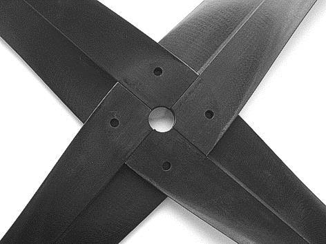
4 2 Description HELIX Propellers have been built since 1990 using composite materials such as carbon fibre, epoxy-resin, epoxy resin foam and aluminium. This combination of materials provides: - High Thrust - Low Noise - Durability Figure 1, 2 and 3: 2-, 3- and 4-blade Propeller of Type H40F The Propeller Blades are made from several layers of woven carbon fibre, reinforced with different sorts of carbon fibre tapes. They are bonded with epoxy resin foam reinforced by glass fibre. This method of construction which ensures that the load is distributed throughout the whole surface of the Blade and dissipates vibration. At voluminous profile series optionally a construction method with three-dimensional-fabric instead of epoxy resin foam is used. This construction method guarantees a low weight combined with high strength and rigidity. Manual H40F page 4 / 9
5 3 Specification of Helix Propeller Type Helix H 40 F 1,60m L - M ( ) Strength Category 25 = 1-10 kw 30 = 5-25 kw 40 = kw 45 = kw 50 = kw 60 = kw Model for H40F F = Fixpitch Diameter in [m] (Meter) Rotating Direction L = Left R = Right Profile and Shape for H40F Z = Straight Shape with small profile-depth and -thickness M = Straight Shape with medium profile-depth and -thickness L = Straight Shape with large profile-depth and -thickness Fixpitch in [ ] (degree) Number of Blades Customer Specific Modifications Table 1: Specification of the Propeller Type, Structure of the Helix Propeller Name Manual H40F page 5 / 9
6 4 Operating Limitations HELIX Propellers are constructed for giving thrust to aircrafts with an engine output of between 1 and 100 kw using 2-stroke, 4-stroke, rotary- or electric engine. The operating limitations for the here described Propeller types of H40F as 2-, 3- and 4- Blade-Version in clockwise and anti-clockwise rotation are for diameters from 1,30m to 1,60m: Maximum Propeller-rpm: rpm Maximum engine power: 47 kw Warning: If the maximum operating values are exceeded the Propeller, engine or gearbox may be damaged. If the Propeller becomes damaged its balance will be affected which can cause failure of the engine mountings. Before starting the engine, the pilot must ensure that the area around the Propeller is free from debris to avoid any impacts on the blades by foreign objects. The engine can only be hand started by qualified personnel. Manual H40F page 6 / 9


7 5 Installation To mount the Propeller Blades together, at first the Blades are placed onto a table, where they are straightened and adjusted. Please note: The Blades for the 4-Blade Propeller have to be mounted according to the label; the paired Blades have to be opposite! 2-blade Propeller: 3-blade Propeller: 4-blade Propeller Figure 4 to 12: Mounting of the blades Please note: The Blades for the 4-Blade Propeller have to be adjusted according to the label; the paired Blades have to be opposite! Warning: At this point it has to be checked that the tailing edge of all Blades is in right position in turning direction backside aligned. Manual H40F page 7 / 9


8 On the propeller must be mounted a pressure plate used with all bolts with a minimum thickness of 5 mm. Figure 13: 3-blade Propeller ex. H30F Figure 14: 4-blade Propeller ex. H40F Finally, the propeller is to be mounted onto the propeller flange of the engine. Screw dimension and tightening torque are to be taken from the manual of the airplane manufacturer and to check. The nominal tightening torque of retaining screws - M8 8.8 amounts 23 Nm in suitable nuts The Propeller can be certainly pursued with a tightening torque in the range of - 19 Nm to 25 Nm for M8 8.8 screws However, the nominal tightening torque for your application is influenced substantially by the used screws and its flange thread. For the application in aluminium components 20 Nm are to be intended for M8 8.8 screws. Generally, the following alternatives available to retain the screws: - the preferred solution is to use a wire as bolt retaining device - for propeller flanges with through holes self locking nuts can be used - if the first alternatives are not possible loctite 243 can be used instead After 3 working hours the mounting of the propeller has to be checked and the screws retightened. Manual H40F page 8 / 9
9 6 Pre-Flight Checks Before every flight the following has to be controlled: - Check engine / Gearbox bearings for excessive play. - All blades are fixed - Check bolts for tightness and security of wire locking - No play of Propellertip - Blades are not damaged and have no cracks Slight resin-flakings by debris can be accepted, but should be repaired shortly. The repair can be done with economical application of special resin. If the check is not satisfactorily the handling has to be stopped and the Propeller repaired. Warning: A propeller failure has more serious consequences than an engine failure! Due to damaged blades an unbalance can arise, which can cause the motor to be torn out of its bracing, thereby changing the proportions of the centre of gravity in such a way that a stable flight attitude cannot be maintained. 7 Maintenance The Propeller should be cleaned at the end of each day s operation. This prevents the built up of dried grass and insects etc. on the blades. Cleaning of the blades should be carried out with a soft sponge using a weak detergent solution. Annually, the Propeller should be polished professionally. It is recommended that this is carried out by a respected coachbuilder or similar facility. 8 Warranty HELIX Carbon GmbH warrants the Propeller for two years from the date of purchase (according to european law). The warranty covers material defects but does not cover subsequent losses. The operator flying with this Propeller does so at his/her own risk. Any claim will only be considered if the Propeller has been installed and used in accordance with this manual. Manual H40F page 9 / 9
Manual for Propeller Type H60V
 Manual for Propeller Type H60V Propeller Type: Propeller Serial No.: Date of Sale: Seal and Signature of Manufacturer: Index 1 List of Modifications... 3 2 Description... 4 3 Specification of the propeller
PROPELLER TYPE SR 200 ON THE GROUND ADJUSTABLE Vodolská Odolena Voda Czech Republic Tel.: Fax:
 PROPELLER TYPE SR 200 ON THE GROUND ADJUSTABLE Vodolská 4 250 70 Odolena Voda Czech Republic Tel.: 00420-283971309 Fax: 00420-283970286 e-mail:info@woodcomp.cz http://www.woodcomp.cz SR 200 ON THE GROUND
FES PROPELLER MANUAL
 FES PROPELLER MANUAL Version 1.0 Type: FES-SIL-P15-100 LZ design d.o.o., Brod 3D, 1370 Logatec, Slovenia tel +386 59 948 898 info@lzdesign.si www.front-electric-sustainer.com Table of Content 1. Important
Universal Projector Ceiling Mount Model: DPM-45
 Universal Projector Ceiling Mount Model: DPM-45 Instruction Manual Images may different from actual product Disclaimer It is Dyconn s intention to have all the correct information represented within this
AFB (AIR FAN BEARING) INSTALLATION GUIDE
 INSTALLATION GUIDE") 654 AFB (AIR FAN BEARING) INSTALLATION GUIDE AFB PARTS Bearing Housing - Secured together with two 3/8 x 1.25 in. Cap Screws Black Wiper Seals - Secured together with O-ring cord (Subsequently depicted
654 AFB (AIR FAN BEARING) INSTALLATION GUIDE AFB PARTS Bearing Housing - Secured together with two 3/8 x 1.25 in. Cap Screws Black Wiper Seals - Secured together with O-ring cord (Subsequently depicted
Fixed Pitch Wooden Propeller Installation, Maintenance and Inspection Manual
 Fixed Pitch Wooden Propeller Installation, Maintenance and Inspection Manual 1 of 8 HPM01 REV. 2 Hercules Propellers Ltd Canal Iron Works Hope Mills Stroud Gloucestershire GL5 2SH United Kingdom +44 (0)
CIRRUS AIRPLANE MAINTENANCE MANUAL
 PROPELLER ASSEMBLY 1. DESCRIPTION The propeller assembly consists of a hollow aluminum hub which supports the propeller blades and also houses the pitch changing mechanism. Movement of propeller blades
INSTRUCTION SHEET STRUT DRIVER RETROFIT KIT PN: 22-79SDRF
 INSTRUCTION SHEET STRUT DRIVER RETROFIT KIT PN: 22-79SDRF COMPONENTS: - Note: Each kit comes with one Strut Driver Gear Case Assembly, one Strut Driver Tube End Adapter Assembly, and a One-Time-Use Threadlocker
installation guide 1 GUIDE#: pwb-assault-001
 assault WAKEBOARD tower installation guide INSTALLATION SUPPORT 1 important information This Aerial wakeboard tower fits motor boats with 76-108 inch wide beam widths. This measurement is taken from the
Self-assembly and pole conversion system
 User Manual Self-assembly and pole conversion system Swivelpole R11, R12 and R13 for self-assembly of lowering poles on greenfield projects or conversion of non-lowering poles on brownfield facilities.
HARDINGE Installation booklet For: Dead-Length Collet Adaptation Chucks Stationary Collet
 HARDINGE Installation booklet For: Dead-Length Collet Adaptation Chucks Stationary Collet Read the enclosed instructions and recommendations before any installations CONTENTS Dead-Length Collet Adaptation
PFW 6851 Display Wall Mount, Turn & Tilt 80 kg INSTALLATION INSTRUCTIONS
 Display Wall Mount, Turn & Tilt 80 kg INSTALLATION INSTRUCTIONS 9531-007-Z00-01 Table of Contents Warning Statements 2 Parts List 3 Installation Tools 3 Wood Stud Installation 5 Concrete Surface Installation
ARROW SAW PRECISE CUT 8000 RPM WITH DUST COLLECTING ATTACHMENT INSTRUCTION BOOK MODEL NO
 ATTENTION If any components of this unit are broken or the unit does not operate properly, please contact Cabela s Customer Service. Retail Store Purchases: 1-800-905-2731 (U.S. & Canada) Catalog and Internet
installation guide 1 GUIDE#: pwb-wwtowv1-pol-003
 g300 WAKEBOARD tower installation guide INSTALLATION SUPPORT 1 important information This WakeWorks wakeboard tower fits motor boats with 76-108 inch wide beam widths. This measurement is taken from the
Comp-DS Driveshaft. User Manual B
 Comp-DS Driveshaft User Manual 2010-1378B Driveshaft Parts List 1.22B 1.21C 1.22C 1.22D 1.21A 1.21B 1.22A 1.1 Figure 1 1.0 Complete Driveshaft 1.1 Tube and Flange Assembly 1.2 Coupling Assembly (2 required
Operators Manual: Diamond Rock Saw Excavator Attachment Austramac Flashcut Series
 Operators Manual: Diamond Rock Saw Excavator Attachment Austramac Flashcut Series! WARNING! Inappropriate use of rock saw may cause serious injury or death. Operators must read this manual before use and
HARDINGE Installation booklet For:
 HARDINGE Installation booklet For: L Flange Nose Dead-Length Collet Adaptation Chucks Draw Collet Read the enclosed instructions and recommendations before any installations WARRANTY & RETURN PROCEDURES
LU6X-130 Instructions and Parts List (including LU6X Basic) Operating Instructions
 Operating Instructions") LORTONE LU6X-130 Item # 061-092 LU6X Basic Item # 061-090 LU6X-130 Instructions and Parts List (including LU6X Basic) Operating Instructions Introduction The LU6X is one the most versatile pieces of equipment
LORTONE LU6X-130 Item # 061-092 LU6X Basic Item # 061-090 LU6X-130 Instructions and Parts List (including LU6X Basic) Operating Instructions Introduction The LU6X is one the most versatile pieces of equipment
PLANISHING HAMMER STAND OWNER S MANUAL
 PLANISHING HAMMER STAND OWNER S MANUAL WARNING: Read carefully and understand all INSTRUCTIONS before operating. Failure to follow the safety rules and other basic safety precautions may result in serious
Installation Instructions
 Installation Instructions XLC Generation 2 Self-aligning split bearing Experience In Motion 1 Equipment Check 1.1 Follow plant safety regulations prior to equipment disassembly: Lock out motor. Wear designated
PRODUCT: LOKI INSTALLATION INSTRUCTIONS. Product is covered by U.S. patents. For more information visit
 R INSTALLATION INSTRUCTIONS PRODUCT: LOKI CONFIGURATION: SINGLE DOOR MOUNT: GLASS MOUNT Product is covered by U.S. patents. For more information visit www.krownlab.com . TOOLS + MATERIALS REQUIRED TOOLS
PAM-200 Universal Projector Mount
 INSTALLATION MANUAL PAM-200 Universal Projector Mount Sony Electronics 16540 West Bernardo Drive San Diego, CA 92127 www.sony.com IN-PAM200.R0 Table of Contents Parts List...- 3 - Installation Tools...-
Retro Fit Gearbox Mount. Assembly Instructions. Assembly Instructions. Before You Start. General Information. Manual No M
 Retro Fit Gearbox Mount Assembly Instructions Treker 4400NT & 4400ST Series Before You Start Assembly Instructions Manual No. 700-372M! When you see this symbol, the subsequent instructions and warnings
Ford / Opel, GM Rose Joint Kit Instruction Booklet GGT-570 For use on car or out of car replacement
 Ford / Opel, GM Rose Joint Kit Instruction Booklet GGT-570 For use on car or out of car replacement 1 of 12 GGT-570 General Instructions Introduction: The GGT-570 Rose Joint kit suits both Ford and Opel
Pole Conversion System For safe and efficient conversion of non-lowering light poles.
 Conversion System USER GUIDE: OVERVIEW The Swivelpole Conversion Tool clamps onto the existing non-lowering pole and safely supports the pole during a cold cut with the Ratchet Pipe Cutter, eliminating
southpaw enterprises, inc.
 southpaw enterprises, inc. Store these instructions with the enclosed maintenance checklist in a safe place. You may also access them on our website. Instruction Sheet Prefab Joist 3 Ft. Drop Ceiling Kit
Travel Trailer Latch With Dead Bolt Trailer Latch With Dead Bolt. U.S. Patent No. 5,927,773
 60-250 Travel Trailer Latch With Dead Bolt 60-251 Trailer Latch With Dead Bolt Service Manual (Installation and Troubleshooting) U.S. Patent No. 5,927,773 CONTENTS 1. BASIC COMPONENTS 2. INSTALLATION OF
OWNER S MANUAL STORAGE SHED MODELS: STOR-96-G-W-1RH & STOR-912-G-W-1RH
 STORAGE SHED MODELS: STOR-96-G-W-1RH & STOR-912-G-W-1RH OWNER S MANUAL Introduction.. 1 Assembly Instructions STOR-96-G-W-1RH... 2 Assembly Instructions STOR-912-G-W-1RH... 8 STOR-96-G-W-1RH Exploded Parts
SC Spare parts list. Hydraulic steel cutter. SC 3600 s/n DEQ Construction Tools GmbH No
 SC 3600 Spare parts list Hydraulic steel cutter SC 3600 s/n DEQ169166-2018 Construction Tools GmbH No. 3390788601 2018-05-09 General information This spare parts list applies to the following: Part number
STRINGING MACHINE OWNER'S MANUAL. Copyright 1998 GAMMA Sports - All Rights Reserved
 6002 STRINGING MACHINE OWNER'S MANUAL Issue 3 - June 20, 1998 Copyright 1998 GAMMA Sports - All Rights Reserved 6002 OWNER'S MANUAL TABLE OF CONTENTS PAGE 1... WARRANTY PAGE 2... FEATURES PAGE 3... ASSEMBLY
southpaw enterprises, inc.
 southpaw enterprises, inc. Store these instructions with the enclosed maintenance checklist in a safe place. You may also access them on our website. Instruction Sheet Wood Joist 2-1/2 Ft. Drop Ceiling
INSTALLATION INSTRUCTIONS
 INSTALLATION INSTRUCTIONS Universal Low Profile Tilt Mount Model: U.S. Toll Free: 1-866-752-6271 Outside N. America: 1-503-748-5799 E-mail: ts@planar.com FRANCE Phone: +33 5 6378 3810 E-mail: emeats@planar.com
Dual Arm Tilt LCD Mount
 Installation Manual model # 51324 M o u n t i n g S y s t e m s Dual Arm Tilt LCD Mount Fits Displays 13 to 32 Supports Up to 50 lbs (23 kgs) Projection from Wall from 3 to 17 Meets VESA Standards 50/75/100,
Front axle components, overview
 j a t Front axle components, overview 40-1 General Information Load bearing components and parts of the suspension must not be welded or straightened. Vehicles without drive axle must not be moved, or
Planishing hammer stand For use with SKU Planishing hammer
 Planishing hammer stand For use with SKU 94847 Planishing hammer Model 96300 Assembly And Operation Instructions Please Note: Planishing Hammer not included with Stand. Due to continuing improvements,
INSTALLATION INSTRUCTIONS
 INSTALLATION INSTRUCTIONS Universal Low Profile Flat Mount Model: U.S. Toll Free: 1-866-752-6271 Outside N. America: 1-503-748-5799 E-mail: ts@planar.com FRANCE Phone: +33 5 6378 3810 E-mail: emeats@planar.com
Ryan STA Sport Scale Model Aircraft Assembly and Instruction Manual
 Ryan STA Sport Scale Model Aircraft Assembly and Instruction Manual Warning: This radio controlled model is not a toy. It requires skill to fly and is not recommended for the novice pilot. It should not
INSTALLATION INSTRUCTIONS
 INSTALLATION INSTRUCTIONS CTM-MS1 Flat Panel Display Mount (26 to 37 ) NORTH AMERICA 3130 East Miraloma Avenue Anaheim, CA 92806 USA USA and Canada Phone: 800-368-9700 Fax: 800-832-4888 Other Locations
Type XTSR71 Sizes
 (Page 1 of 13) s 494-5258 Type XTSR71 s 494-5258 Figure 1 Thomas XTSR71 Coupling 1. General Information 1.1 Thomas Couplings are designed to provide a mechanical connection between the rotating shafts
Installation Instructions
 Installation Instructions XLC Series Self-aligning split bearing Experience In Motion 1 Equipment Check 1.1 Follow plant safety regulations prior to equipment disassembly: Lock out motor. Wear designated
APPLICATION NOTE. Mounting instructions for EasyPIM / EasyPACK modules with screw clamps. 1. General information
 APPLICATION NOTE Date:2003-02-14 Page 1 of 10 with screw clamps 1. General information The mounting instructions outlined below are recommended for the safe and reliable operation of these modules in industry
Page 1. SureMotion Quick-Start Guide: LACPACC_QS 1st Edition - Revision A 03/15/16
 R K C T I Repair Kit Product Compatibility Repair Kit # Linear Actuator Assembly # LACPACC-002 LACPACC-003 LACP-16TxxLP5 (0.5-in lead screw pitch) LACP-16TxxL1 (1-in lead screw pitch) C P I R K 4 ea Flanged
INSTALLATION INSTRUCTIONS
 INSTALLATION INSTRUCTIONS R5 STEP BOARD APPLICATION: 2009-2017 Dodge Ram 1500 Quad / Crew Cab 2010-2017 Dodge Ram 2500/3500 Crew Cab PART NUMBER: 28-51040, 28-51045, 28-51050, 28-51055 ITEM QUANTITY DESCRIPTION
1904, 1904Pg, 1904PgSB, and 1906SB High Capacity Ratchet Knockout Drivers
 INSTRUCTION MANUAL 1904, 1904Pg, 1904PgSB, and 1906SB High Capacity Ratchet Knockout Drivers Read and understand all of the instructions and safety information in this manual before operating or servicing
DUMP N GO MODEL PV 212 JOHN DEERE
 DUMP N GO MODEL PV 212 JOHN DEERE 8722 E Research Center Rd. New Hope, MN 55428 Ph: 763-535-4038 Fax: 763-535-4633 PV 212 shown on John Deere Model X500 Fits models: LX/GT and GX ASSEMBLY INSTRUCTIONS
Rev B C-RING TOOL VA0375 ½ in. OPERATING MANUAL
 Rev B 4-30-0 C-RING TOOL VA0375 ½ in. OPERATING MANUAL Operational Instructions for Vertex C-Ring Tool VA0375 Vertex Fasteners is committed to providing our customers with world-class customer service
DUMP N GO MODEL PV 212 FERRIS
 DUMP N GO MODEL PV 212 FERRIS 8722 E Research Center Rd. New Hope, MN 55128 Ph: 763-535-4038 Fax: 763-535-4633 PV 212 shown on Ferris IS1500Z Fits Ferris Zero-Turn mower models: IS500Z, IS1500Z, IS2000Z,
GT Series Grooving Tool
 GT Series Grooving Tool Tube & Pipe Cleaners Tube Testers Tube Plugs Tube Removal Tube Installation Operating and Maintenance Instructions www.elliott-tool.com TABLE OF CONTENTS Introduction... 4 Safety
Installation Instructions
 The IMS ETERNAL FIX PATENT PENDING Installation Instructions EPS recommends professional installation for the Eternal IMS Fix. Please take all precautionary safety measures. We also recommend putting the
installation guide 1 GUIDE#: pwb-assault-004
 assault WAKEBOARD tower installation guide INSTALLATION SUPPORT 1 important information This Aerial wakeboard tower fits motor boats with 76-108 inch wide beam widths. This measurement is taken from the
Lab Style Table Frame Part No Assembly Guide Automation Technology
 Ergonomic Workstations Lab Style Table Frame Part No. 8 0 Assembly Guide 7 90 70 Automation Technology SPECIFICATIONS Lab style frame part number... 80 Height... 70 mm (8.") Width... 90 mm (.7") Depth...
Installation Instructions
 Installation Instructions Ceiling Mount Bracket for DLP Based Projectors (for High Ceilings) Model No. ET-PKD100H Contents Important Safety Notice.................. 2 For DLP Based Projector: PT-D10000
Read through the Operator's Manual carefully and understand the content before using the machine.
 Operator's Manual 123L J-Handle Kit Read through the Operator's Manual carefully and understand the content before using the machine. These instructions supplement the instructions that were included with
NOVA-EXT Versatile Projector Mount Model: NOVA-EXT
 INSTALLATION MANUAL NOVA-EXT Versatile Projector Mount Model: NOVA-EXT NORTH AMERICA 3130 East Miraloma Avenue Anaheim, CA 92806 USA USA and Canada Phone: 800-368-9700 Fax: 800-832-4888 Other Locations
1. Turn off or disconnect power to unit (machine). 2. Push IN the release bar on the quick change base plate. Locking latch will pivot downward.
. 2. Push IN the release bar on the quick change base plate. Locking latch will pivot downward.") Figure 1 Miniature Quick Change Applicators, of the end feed type, are designed to crimp end feed strip terminals to prestripped wires. Each applicator is set up to accept the strip form of certain specific
Figure 1 Miniature Quick Change Applicators, of the end feed type, are designed to crimp end feed strip terminals to prestripped wires. Each applicator is set up to accept the strip form of certain specific
MOUNTING INSTRUCTIONS CONCRETE PURLIN BRACKET
 CONCRETE PURLIN BRACKET VERSION MARCH 2015 GENERAL INSTRUCTIONS Safety: Systems may only be installed and operated by properly trained and technically suitable people (i.e. MCS accredited installers).
GlideRite Retractable Cover System For HotSpring & Tiger River Spas (except Classic & pre-2000 Landmark Spas)
") List of Contents Quantity Description 12 #10 x 1 ½ Flat Head Phillips Screw (see pg. 2) 2 #10 x ½ Pan Head Phillips Screw (see pg. 2) 8 ¼ x 2 ½ Lag Bolt (see pg. 2) 7 ¼ 20 x 5 / 8 Hex Head Bolt (see pg.
List of Contents Quantity Description 12 #10 x 1 ½ Flat Head Phillips Screw (see pg. 2) 2 #10 x ½ Pan Head Phillips Screw (see pg. 2) 8 ¼ x 2 ½ Lag Bolt (see pg. 2) 7 ¼ 20 x 5 / 8 Hex Head Bolt (see pg.
SLW 6 Channel Letter Brake. User Guide. Operation and Mounting Instructions
 SLW 6 Channel Letter Brake User Guide Operation and Mounting Instructions Scope This document describes the operation and mounting instructions for the SLW 6" Channel Letter Brake. Please read all instructions
Mechanical Actuators
 Mechanical Actuators Rotating Machine Screw Actuators 2-Ton and Larger Capacity Installation, Operation & Maintenance Instructions Publication Part No. SK-2389-R CAUTION This manual contains important
ITEM NO. PART NO DESCRIPTION QTY.
 PUMP MAINTENANCE ITEM NO. PART NO DESCRIPTION QTY. 1 52002 Center Case 1 2 52052 Back End Plate 1 3 52051 Front End Plate 1 4 55090 Octagonal Nut 1 5 53001 Idler Gear 1 6 53002 Drive Gear 1 7 28062 Bushing
3 Emergency Breakaway Coupling
 SM64227 July 2008 Applicable addition manuals: N/A Aerospace Group Conveyance Systems Division Carter Ground Fueling Maintenance & Repair Manual 3 Emergency Breakaway Coupling Model 64227 Table of Contents
Specifications. Important Safety Information
 Specifications Tire Rim Capacity 4 to 12 Rim Height 16 (2) Bead Breaker Handles 21 Long Includes Aluminum Centering Cone (2) Nylon Spacers Important Safety Information 1. Do not exceed max. tire capacity.
DO35 MAINTENANCE INSTRUCTIONS
 CUSTOMER INFORMATION SHEET NO. 038 DO35 MAINTENANCE INSTRUCTIONS (DO35 V3 LAUNCHED PRODUCTION JUNE 2017) Table of Contents 1.0 Replacing Spindle Bushes V3... 22 2.0 Replacing Locking Mechanism V3... 6
AutoSPLITTER STRAIGHT HEAD MODELS
 AutoSPLITTER STRAIGHT HEAD MODELS HYDRAULIC NUT SPLITTER OPERATIONS AND MAINTENANCE MANUAL 1 CONTENTS INTRODUCTION... Page 3 WARNINGS AND SAFETY TIPS... Page 4 POWER REQUIREMENTS... Page 5 ASSEMBLY...
PLOW MOUNT KIT FOR POLARIS RANGER P/N ASSEMBLY / OWNERS MANUAL
 PLOW MOUNT KIT FOR POLARIS RANGER P/N 34-3010 ASSEMBLY / OWNERS MANUAL Application PLOW PUSH FRAME NO. 34-0000 or 34-0070 Before you begin, please read these instructions and check to be sure all parts
Tuf-Lite and Tuf-Lite II Fans 4000 Series Hub
 Tuf-Lite and Tuf-Lite II Fans 4000 Series Hub INSTALLATION MANUAL Hudson Tuf-Lite and Tuf-Lite II fan blades Adjustable Pitch Fan Assembly 15 thru 20 Diameter Hudson Tuf-Lite (black) fan blades are made
AUC Cell Alignment Tool. User Manual
 AUC Cell Alignment Tool User Manual WARRANTY Spin Analytical Inc., warrants this product to be defect free in both material and workmanship for 90 days from the date of shipment. Labor services are guaranteed
8-Ton Manual Splitter OWNER S MANUAL
 8-Ton Manual Splitter OWNER S MANUAL WARNING: Read carefully and understand all ASSEMBLY AND OPERATION INSTRUCTIONS before operating. Failure to follow the safety rules and other basic safety precautions
INSTALLATION INSTRUCTIONS
 CREATING POSITIVE CUSTOMER EXPERIENCES INSTALLATION INSTRUCTIONS Universal Low Profile Tilt Mount for 42 to 63 Flat Panels NORTH AMERICA 3130 East Miraloma Avenue Anaheim, CA 92806 USA USA and Canada Phone:
9 PIECE TUNGSTEN CARBIDE HOLE SAW KIT. Model 90721
 9 PIECE TUNGSTEN CARBIDE HOLE SAW KIT Model 90721 Set up And Operating Instructions Diagrams within this manual may not be drawn proportionally. Due to continuing improvements, actual product may differ
H8508 Impact Wrench SERVICE MANUAL. Model (Serial Code FWN) Model (Serial Code FWP)
 Model (Serial Code FWP)") SERVICE MANUAL H8508 Impact Wrench Model 48755 (Serial Code FWN) Model 48760 (Serial Code FWP) Read and understand all of the instructions and safety information in this manual before operating or servicing
SERVICE MANUAL H8508 Impact Wrench Model 48755 (Serial Code FWN) Model 48760 (Serial Code FWP) Read and understand all of the instructions and safety information in this manual before operating or servicing
Top spin Nr /
 Top spin Nr. 1840 0000 / 1840 1000 Bedienungsanleitung 21-6680 28052014 / A Made in Germany Ideas for dental technology Top spin Nr. 1840 0000 / 1840 1000 Contents 1. Introduction...2 1.1 Symbols...2 2.
VIBRATORY SCREED OPERATOR S MANUAL AND PARTS BOOK
 VIBRATORY SCREED OPERATOR S MANUAL AND PARTS BOOK 31 SUN PAC BLVD. BRAMPTON ONTARIO L6S 5P6 PHONE: 866-501-5484 FAX: 905-458-5484 TABLE OF CONTENTS Specifications Page 1 Engine Assembly Page 2 5 Base Section
MUELLER. Improved, Centurion Series, Modern Improved, and 107. Fire Hydrants. Inserting Extention Sections. Reliable Connections
 insertion Instructions manual MUELLER Improved, Centurion Series, Modern Improved, and 107 table of contents PAGE Centurion Series Fire Hydrant Adding an Extention 2-3 Improved Fire Hydrant Inserting Extention
Installation Instructions
 Installation Instructions For 4 foot / 1.2m Diameter Ultra-high Performance Antenna Model ADxxG-4-T2 Before Installation, please read the instructions carefully. This instruction guide covers the installation
F-150 Structural Holding System
 F-150 Structural Holding System Users Manual December 2013 by Vehicle Service Group. All rights reserved. CO8812.2 502073 Rev. - 12/11/2013 CHIEF'S LIMITED ONE-YEAR WARRANTY & LIABILITY Chief Automotive
Congratulations on your purchase of a DAVCO
 WELCOME Congratulations on your purchase of a DAVCO Manufacturing, Model BC705SS Brush Cutter. The DAVCO Brush Cutter, when combined with a Skid Steer or CTL with 21-30 GPM s, will provide you with unmatched
Publication Part No. SK
 Publication Part No. SK-463- Translating Tube Actuators Model Numbers M-464 & M-465 Rotating Screw Actuators Model Numbers M-46 & M-463 Caution This manual contains important information for the correct
ATV Disc OWNER S MANUAL
 ATV Disc OWNER S MANUAL WARNING: Read carefully and understand all ASSEMBLY AND OPERATION INSTRUCTIONS before operating. Failure to follow the safety rules and other basic safety precautions may result
1 of 2 3/3/2017 4:49 PM
 1 of 2 3/3/2017 4:49 PM Front Door Window, Assembly Overview 1 - Window guide - Inserted on flange 2 - Door 3 - Inner window recess seal - Inserted on flange 4 - Bolt - 20 Nm 5 - Carrier assembly - Window
Owner s Manual & Safety Instructions
 Owner s Manual & Safety Instructions Save This Manual Keep this manual for the safety warnings and precautions, assembly, operating, inspection, maintenance and cleaning procedures. Write the product s
P4263TP. Installation Guide. Low-Profile Tilting Portrait Mount for Flat-Panels
 Low-Profile Tilting Portrait Mount for Flat-Panels 1321 S. State College Blvd., Fullerton, CA 92831 USA Weight Limit Maximum Flat Panel Weight: 175 lbs. Warning Statements THE WALL STRUCTURE MUST BE CAPABLE
43in EPP Acrocub Instruction Manual
 43in EPP Acrocub Instruction Manual Specifications Wingspan: 43.3in (1100mm) Length: 41.3in (1050mm) Flying Weight: Approx. 1.5lb (670g) Dear Customer, Congratulations on your purchase of 43in EPP Acrocub
Page 1. SureMotion Quick-Start Guide: LARSACC_QS 1st Edition - Revision A 03/15/16. Standard Steel Bolt/Screw Torque Specifications
 R K C T I Repair Kit Product Compatibility Repair Kit # Linear Actuator Assembly # LARSACC-013 LARSACC-014 LARSD2-08T12BP2C (12-in travel) LARSD2-08T24BP2C (24-in travel) C P I R K 1 ea Ball Screw with
Owner s Manual & Safety Instructions
 Owner s Manual & Safety Instructions Save This Manual Keep this manual for the safety warnings and precautions, assembly, operating, inspection, maintenance and cleaning procedures. Write the product s
RYAN STA SAFETY PRECAUTIONS. "Sport Scale E-Power ARF" For Intermediate and Advanced Fliers. This radio control model is not a toy!
 RYAN STA "Sport Scale E-Power ARF" For Intermediate and Advanced Fliers. SAFETY PRECAUTIONS This radio control model is not a toy! First-time builders should seek advice from people with model building
4Post Server Rack-111 Assembly For Floor Anchored Models
 4Post Server Rack-111 Assembly For Floor Anchored Models Patent(s) Pending Installation Instructions Kit P/N: 111-1720 111-1721 111-1722 111-1723 111-1724 111-1767 111-2325 111-2257 111-2408 111-2457 111-2458
SLIDE GATE SERVICE CONDITIONS
 SLIDE GATE The model is a 4 side sealing slide gate designed for wall mounting. It is used mainly in water treatment, irrigation, hydraulic works and hydroelectric power plants. There are two different
REPAIR INSTRUCTIONS. Cat. No Cat. No MILWAUKEE ELECTRIC TOOL CORPORATION. SDS Max Demolition Hammer. SDS Max Rotary Hammer
 Cat. No. 9-0 SDS Max Demolition Hammer Cat. No. -0 SDS Max Rotary Hammer MILWAUKEE ELECTRIC TOOL CORPORATION W. LISBON ROAD BROOKFIELD, WISCONSIN 00-0 8-9-0 d 000 8-9-0 d Special Tools Require Forcing
Motorized M3 AX7200 Rotary-Style Gasket Cutter Operating Instructions
 Motorized M3 AX7200 Rotary-Style Gasket Cutter Operating Instructions INTRODUCTION Congratulations! You are the owner of the finest rotary-style gasket cutter in the world. Originally developed and patented
HBS-AP ASSEMBLING INSTRUCTIONS
 ALUMINIUM PIPEWORK - ALUMINIUM PIPEWORK - ALUMINIUM PIPEWORK 97 HBS-AP ASSEMBLING INSTRUCTIONS 1. INTRODUCTION 1.1. This manual is very easy to consult and we recommend reading it before starting work,
Cartridge Machine USER MANUAL
 Cartridge Machine USER MANUAL 2018 USER MANUAL MACHINE OVERVIEW PACKAGE CONTENTS User Manual, Spektra Edge Body Hex Drive MotorBolt Oil Lubricant 0.05 Hex Screwdriver Spare 4-40 3/16 Stroke Set Screw Spare
Mounting systems for solar technology
 Mounting systems for solar technology ASSEMBLY INSTRUCTIONS Crosshook 3S CrossHook 4S GB Table of contents TABLE OF CONTENTS THE COMPANY SAFETY REGULATIONS MATERIALS REQUIRED TOOLS REQUIRED ASSEMBLY 2
User Manual. Where Imagination Meets Innovation. FRESH AERO Easy Seat Tool For Grumman AA1 & AA5 Series Aircraft
 FRESH AERO Easy Seat Tool For Grumman AA1 & AA5 Series Aircraft Alpha Model For Grumman AA-1 & AA-5 Series Aircraft with Access Holes in Front Seat Buckets User Manual The Steelebrook Group Where Imagination
A-dec 6300 Ceiling-Mount Dental Light INSTALLATION GUIDE
 A-dec 6300 Ceiling-Mount Dental Light INSTALLATION GUIDE Recommended Tools Hex key set Plumb bob Drill 3/16" drill bit 6' piece of tubing Level Phillips head screwdriver Tape measure Anti-static strap
GlideRite Retractable Cover System For Hot Spot Spas (SE & SLX only)
") List of Contents Quantity Description 12 #10 x 1 ½ Flat Head Phillips Screw (see pg. 2) 2 #10 x ½ Pan Head Phillips Screw (see pg. 2) 8 ¼ x 2 ½ Lag Bolt (see pg. 2) 7 ¼ 20 x 5 / 8 Hex Head Bolt (see pg.
List of Contents Quantity Description 12 #10 x 1 ½ Flat Head Phillips Screw (see pg. 2) 2 #10 x ½ Pan Head Phillips Screw (see pg. 2) 8 ¼ x 2 ½ Lag Bolt (see pg. 2) 7 ¼ 20 x 5 / 8 Hex Head Bolt (see pg.
LASER ENHANCED REVOLVER GRIP OWNER S MANUAL RED LASER GREEN LASER
 LASER ENHANCED RED LASER GREEN LASER REVOLVER GRIP OWNER S MANUAL LASER ENHANCED GRIP Installation Instructions Caution... 3 Safety Labels... 4 Installation...5-7 Programming...8-10 Batteries (Red Laser)...
Axles Covered in This Bulletin. How to Obtain Additional Maintenance, Service and Product Information. Product Design Variations. How to Obtain Kits
 Technical Bulletin Revised 09-7 Carrier-to-Housing Joint Reseal Procedure Service procedure to be used any time a carrier is removed and reinstalled. Includes tapered dowel installation information. All
Manual for the Feathering Propeller. DF blade model
 Manual for the Feathering Propeller DF-260 4 blade model Installation on the shaft page 2 Operation page 3 Pitch adjustment LH ( left-hand rotation propeller ) page 4 Pitch adjustment RH ( right-hand rotation
linear/swivel clamp CLR Operating instructions e [ ]
![linear/swivel clamp CLR Operating instructions e [ ]](/thumbs/76/73629285.jpg "linear/swivel clamp CLR Operating instructions e [ ]") linear/swivel clamp CLR en Operating instructions 8072624 2017-05e [8072626] Translation of the original instructions CLR-EN Identification of hazards and instructions on how to prevent them: Danger Immediate
linear/swivel clamp CLR en Operating instructions 8072624 2017-05e [8072626] Translation of the original instructions CLR-EN Identification of hazards and instructions on how to prevent them: Danger Immediate