PASSIVE SOLAR-HEATED GREENHOUSE
|
|
|
- Matilda Carson
- 5 years ago
- Views:
Transcription


1 PASSIVE SOLAR-HEATED GREENHOUSE Actual greenhouse length may differ from what is shown. SOLAR-HEATED GREENHOUSE Use these instructions for the following greenhouse skus: (Length: 20') (Length: 30') (Length: 40') (Length: 50') (Length: 60') 2009 ClearSpan All Rights Reserved. Reproduction of content is prohibited without permission. Revision date:
2 Identify whether underground cables and pipes are present before preparing the site, driving ground posts (if equipped), or anchoring the structure. Location should be away from structures that could cause snow to drift on or around the building. YOU MUST READ THIS DOCUMENT BEFORE YOU BEGIN TO ASSEMBLE THE SHELTER. Thank you for purchasing this ClearSpan greenhouse. When properly assembled and maintained, this product will provide years of reliable service. This instruction manual includes helpful hints and important information needed to safely assemble and properly maintain the shelter. Please read these instructions before you begin. If you have any questions during the assembly, contact Customer Service at for assistance. SAFETY PRECAUTIONS Wear eye protection. Wear head protection. Wear gloves when handling metal tubes and cables. Use a portable GFCI when working with power tools and cords. Do not climb on the shelter or framing during or after construction. (See Ridge Cap Installation notes.) Do not occupy the shelter during high winds, tornadoes, or hurricanes. Provide adequate ventilation if the structure is enclosed. Do not store hazardous materials in the shelter without proper ventilation. Provide proper ingress and egress to prevent entrapment. Do not position the building in a place where large loads such as snow and ice, large tree branches, or other overhead obstacles could fall. SITE After choosing a location, proper preparation of the site is essential. The following site characteristics will help ensure the integrity of the structure. A level site is required to properly and safely erect and anchor the structure. Drainage: Water draining off the structure and from areas surrounding the site should drain away from the site to prevent damage to the site, the structure, and contents of the structure. WARNING: The individuals assembling this structure are responsible for designing and furnishing all temporary bracing, shoring and support needed during assembly. For safety reasons, those who are not familiar with recognized construction methods and techniques must seek the help of a qualified contractor. QUICK START SECTION For a quick overview of this greenhouse and its components, consult the Quick Start section at the back of these instructions. ANCHORING INSTRUCTIONS Prior to assembling this shelter, please read the MUST READ document included with the shipment. WARNING: The anchor assembly is an integral part of the shelter construction. Improper anchoring can cause shelter instability and failure of the structure to perform as designed. Failing to anchor the shelter properly will void the manufacturer's warranty and may cause serious injury and damage. LOCATION Choosing the proper location is an important step before you begin to assemble the structure. The following suggestions and precautions will help you determine whether your selected location is the best location. Never erect the structure under power lines. 1 of 84
3 ASSEMBLY PROCEDURE Following the instructions as presented will help ensure the proper assembly of your shelter. Failing to follow these steps can result in an improperly assembled and anchored shelter. The steps outlining the basic assembly processes are as follows: 1. Verify that all parts are included in the shipment. Notify Customer Service for questions or concerns. 2. Read these instructions, the Must Read document, and all additional documentation included with the shipment before you begin assembling the shelter. 3. Gather the tools, bracing, ladders (and lifts if needed), and assistance needed to assemble the shelter. Check the weather before you install the main cover and any end panels. Do not install end panels (if equipped) and main cover on a windy or stormy day. 4. Re-evaluate the location and site based on the information and precautions presented in the documentation included with the shipment. 5. Lay out the site (if this has not been completed). 6. Construct the water wall frame and related supports. 7. Set rafter ground posts and assemble the frame components in the order they are presented in these instructions. 8. Frame the end walls and install the door. 9. Install the final purlin and assemble and attach the roller tracks. 10. Install end wall polycarbonate panels and the roll-up panel. 11. Install the main cover, inflation fan kit, twist-of-thewrist assembly, and the anti-billow ropes. 12. Prepare the insulation blanket, assemble rollers for the insulation blanket, attach rollers to blanket, and install blanket. 13. Read the Greenhouse Care and Maintenance information at the end of these instructions. DOUBLE-LAYER FILM INSTALLATION Greenhouses equipped with a double-layer film include a layer that is Infra Red (IR) Retention film. IMPORTANT! During cover installation, the IR film must be installed first! Examine the film and install it according to the instructions printed on the film. LIST OF WORDS AND PHRASES Before you begin to assemble your greenhouse, it is important to become familiar with the words and phrases used in this instruction manual. The words and phrases below are common to most ClearSpan shelters and identify the different parts of the shelter. (Some are used in this document. Others may not apply to this particular shelter.) These terms are used to describe the shipped parts and can also be found on the materials list/spec sheets included with the shipment. To aid in the assembly, read through the following definitions before you begin to assemble your shelter. Band Clamp: Clamp used to connect the end wall framing to the rafter pipe. In some cases, band clamps are used to connect diagonal struts to the assembled frame. Clip or Fabric Clip: A short, half-section piece of conduit (cut lengthwise) used to secure the fabric end panel to the leg or rafter assembly. The clip or fabric clip is typically fastened in place using selftapping Tek screw. Clips are not used when the end walls are covered with polycarbonate panels. Conduit: An assembly of pipes used to secure the main cover and end panels (if equipped). Purlins and some strut assemblies also consist of connected pipes to form a conduit. Each pipe joint of a conduit assembly is secured with a self-tapping Tek screw. Some conduit assemblies are used to secure larger fabric end panels and main covers. These conduits typically consist of sections of PVC tubing glued at the joints. Cross-connector: Any one of the metal brackets used to "connect" or secure a purlin to a rafter. Cross-connectors are typically pictured on the Pictorial Parts Guide page and in the Quick Start section of these instructions. End Panel: Fabric or polycarbonate used to cover the end wall assemblies. End wall assemblies are optional for many shelters. Main Cover: Fabric or polycarbonate used to cover the roof and, in some instances, the sides of the shelter. Must Read Document: This document includes building and shelter anchoring instructions, steps for end wall reinforcement, safety precautions, and notices and warnings. The Must Read document is sent with all shelters and buildings. If you did not receive a Must Read document, contact Customer Service at to request one. 2 of 84
4 Purlin: The pipe assembly that runs perpendicular to the rafters or framework that supports the main cover. Purlins are found on the sides and roof areas of the assembled frame, are evenly spaced, and typically run from the front to the back of the shelter. Plain or Straight Pipe: A term used to describe a pipe that has the same diameter throughout its entire length. Strut: A strut is usually a length of pipe with two flattened ends used for diagonal bracing of the shelter frame. A strut is typically secured to the framework by special brackets and bolts. Struts are usually found on longer shelters. Swaged End or Swaged Pipe: The term "swaged" refers to the tapered end of the pipe. Swaged ends of a pipe can be inserted into couplers and the straight ends of other pipes. Tek Screw: A self-tapping fastener used to secure pipe joints and to fasten brackets to rafters. REQUIRED TOOLS The following list identifies the main tools needed to assemble the shelter. Additional tools and supports may be needed depending on the structure, location, and application. These are identified elsewhere in this manual. Tape measure or measuring device Marker to mark locations on the pipes Variable speed drill and impact driver (cordless with extra batteries works best) Metal-cutting saw Wrenches and impact socket set, or an adjustable wrench Scissors, utility knife, tin snips Hammers and gloves to drive ground posts Adjustable pliers and self-locking pliers Ladders, work platforms, and other machinery for lifting designed to work safely at the height of the building Safety equipment for head, hands, feet, and eyes. 2. Verify that all parts listed on the Bill of Materials/Spec Sheets are present. If anything is missing or you have questions, consult the Pictorial Parts Guide and all diagrams for clarification, or contact customer service at NOTE: At this time, you do not need to open the plastic bags containing the fasteners and clamps. SPECIAL NOTE: Baseboards for Frame These instructions describe installing a baseboard (recommended) at ground level. The baseboard runs from the front to the back of the frame. This baseboard is not included with the shipment and must be supplied by the customer. Treated or recycled plastic lumber works well for a baseboard. The baseboard, when installed properly, helps prevent the ground posts from sinking into the ground when anchored. Depending on the building, it also provides a surface to attach struts or other building components to. If used, the baseboard is installed after the ground posts for the rafters are properly installed. Consult these instructions, or contact Customer Service for additional information regarding baseboards. UNPACK AND IDENTIFY PARTS The following steps will ensure that you have all the necessary parts before you begin to assemble the shelter. 1. Unpack the contents of the box and place them where you can easily inventory the shipment. Refer to the Bill of Materials/Spec Sheets. 3 of 84


 to the rafter")


5 Pictorial Parts Guide Not all parts are shown. The following graphics and photos will help you identify the different parts and show you how they are used. (Not all parts are shown.) Tube Fitting (1-Way) Cross Connector securing a purlin (small pipe) to the rafter assembly. Band Clamp Connector QH1330 Bracket Band Clamp secures the connector to the rafter and end wall frame. Baseboard supplied by customer. Ground Post Ground Level Ground post with attached baseboard. The customer supplies the baseboard. View from inside of frame. Frame shown may differ from actual frame. End Clamp 4 of 84
 Interior Rafter End Rafter Purlin Ground Level End Frame Base Rail Vertical Water Wall Frame Tubes and Water")
6 Basic Frame Diagram (Frame length may differ from actual frame. It is used for illustration only.) Interior Rafter End Rafter Purlin Ground Level End Frame Base Rail Vertical Water Wall Frame Tubes and Water Bag Shelves 5 of 84
7 ATTENTION: The procedure below describes the basic steps needed to square the location of the frame. If you are unfamiliar with the steps needed to square a site, consult the services of a professional contractor to get started. The frame and the ground posts must be square to properly assemble this greenhouse. LAYOUT THE SITE The following steps describe one way to prepare the site. 1. Identify a corner of the site and drive a temporary stake to mark the location. 2. Determine how you want the building to sit and stretch a string line as long as the greenhouse in the desired direction. 3. Drive a temporary stake to mark that location and tie the string to the stake. 4. Use the information below to drive another stake and to stretch another string line at a right angle to mark a position for the water wall frame and the ground posts for the rafters. A transit can be used to ensure an accurate 90 angle, or the rule can be used. See the diagram below. Regardless of length, using multiples of such as or helps to maintain an accurate 90 angle. Example shows a measurement at 3' along one line and a 4' measurement along the other. The diagonal measurement when the two lines are at 90 will be 5'. 5. Once you have squared the site for the building, continue by constructing the water wall frame. 6 of 84
, and clamps to secure 2\" x 4\" bracing boards to vertical frame members, saw to cut metal and wood.")


8 Required Tools: Tape measure, shovels, posthole digger (or other means to dig footings), 2" x 4" boards for bracing, hammer, drill or power driver to drive Tek screws (to secure column cap to top of frame members), and clamps to secure 2" x 4" bracing boards to vertical frame members, saw to cut metal and wood. CONSTRUCTING THE WATER WALL FRAME When constructed properly, the water wall frame is anchored in place with concrete. The vertical frame supports are set 48" below the finished grade. IMPORTANT! To properly support the weight of the water bags, the main greenhouse frame, and the forces applied to that frame, you must assemble and anchor the water wall frame as described in these instructions. Failing to follow these steps may cause property damage or personal injury or both. CONSULT THE SERVICES OF A PROFESSIONAL CONTRACTOR TO PROPERLY COMPLETE THE STEPS THAT FOLLOW IF YOU ARE NOT FAMILIAR WITH BASIC CONSTRUCTION PRACTICES. Complete the following steps: 1. After squaring the site, use the string line as a guide and mark the general locations of the holes that you need to dig to set each set of vertical water wall frame members. Consult the diagrams in the Quick Start section at the back of these instructions to determine the spacing of the water wall frame members. The above photos show where the water wall frame will be set. Holes were dug using a 24" auger. Dashed lines show the approximate edges of the building site. 2. Dig the holes to a depth that will allow 48" of the vertical supports to be anchored in concrete. Remove loose materials from the site and continue with the next step. SPACE HOLES AT 60" ON CENTER. 3. Locate the 2" x 3" rectangular tubes (R23P17175) for the vertical frame members of the water wall frame and set these in an area where they can be prepared. 4. Measure 48" from one end on each tube and mark the location. This line will be even with the finished grade when the vertical frame tubes are properly set. (The 48" section of each post is the bottom; it is placed in the hole.) 7 of 84
 different column caps for this frame.")

 Consult the diagrams in the Quick Start section (at the back) for additional details. 6.")

9 5. Take two of the marked tubes and insert the column cap into the top of each post as shown below. Flange Column Cap 16" Outside-to-Outside Water Wall Verticals x x NOTE: There are three (3) different column caps for this frame. For the end wall framing to install properly, install these column caps as instructed below. Position the flange of the different caps so that the outside edge of each end rafter is in line with the outside edge of the vertical frame members of the water wall frame. Consult the diagrams for additional details. When this assembly is set in the ground, the flange is positioned to the outside surface of the greenhouse. (This is to the backside of the water wall frame.) Consult the diagrams in the Quick Start section (at the back) for additional details. 6. To secure the cap in place, install a Tek screw through each vertical in a location that will not interfere with the installation of the end wall. DO NOT INSTALL A TEK SCREW ON EITHER OF THE SURFACES MARKED WITH AN X IN THE ABOVE PHOTO. 7. Cut a 16" cross brace from an 8' support (XR3776) and temporarily secure it to the 2" x 3" vertical tubes approximately 60" from the tops of each tube to maintain the spacing set by the cap. This cross brace is removed and used in a different location later in these instructions. 60" 48" Top Column Cap 16" Cross Brace Vertical frame tubes are parallel. Bottom NOTE: The 16" cross brace is temporarily attached to maintain even spacing between the verticals. The outside-tooutside dimension regarding the above vertical assembly is 16". 8. With the first set of verticals assembled, set the assembly in the first footing hole. This will be the position on the right when looking at the site and building location standing where the rafter ground posts will be set in a later step. This photo shows a 2" x 4" block used to maintain the spacing of the verticals. View from this position. Ground Level Install first verticals here. 8 of 84


10 9. With the first vertical assembly set in the footing hole as previously shown, assemble all inside (middle) vertical frame pairs using 2" x 3" tubes, the column caps, and the previous steps as guides. When the assemblies are complete, set each in the inside footing holes. NOTE: When setting all assemblies in the footing holes, verify that the flange of each column cap is positioned as shown in the QUICK START diagrams and as shown below. To the inside of the greenhouse. Rafter Assembled rafter is attached to the column cap in a later step. Outside the greenhouse. 10. Assemble the final vertical pair as previously described and use the column cap for the top. Set this assembly in the last footing hole. 11. Plumb and brace all vertical pairs. The following photos show one way to prepare the frame for the concrete. Space the vertical assemblies as shown in the diagram on the next page. In this example, clamps and 2" x 4" boards are used to position and brace the vertical frame tubes before concrete is added. 12. Verify that the 48" line is at the finished grade level and that all verticals are properly aligned. 9 of 84


11 View shows the water wall frame as seen from inside the greenhouse. Vertical pair on the right has the cap and the vertical on the left has the cap installed. In the photo below, the dashed line shows where the finished grade will be. It also marks the 48" line on each of the vertical assemblies. LEFT Center-to-Center 59-1/4" 60" 60" 59-1/4" Dimensions are center-to-center. 13. With the frame set, plumbed, and braced, fill holes with concrete to anchor the water wall frame. Allow the concrete to remain a few inches below the 48" finished grade line to prevent conflicts during the remainder of the frame assembly. Allow the concrete to set before removing the bracing. IMPORTANT! Use the following information when spacing the vertical assemblies for the water wall frame: As shown in the upper-left diagram, the on-center spacing between the end vertical and the first interior vertical at each end of the frame is 59 ¼". Wood Bracing The on-center spacing between all interior verticals (i.e., those between the end verticals) is 60". These dimensions are valid regardless of the length of the shelter. 14. Once the concrete has set, remove all 2" x 4" bracing and the 16" cross braces that were installed when the vertical frame members were assembled. Set the 16" cross braces aside to be used later. 15. Continue by attaching the horizontal frame, ratchets, and straps for the water wall frame. 10 of 84

12 ATTENTION: Customer is responsible for supplying all additional materials to finish and insulate the water wall frame as shown in the photos below. If using plywood, a minimum of ¾" plywood is required for the shelves on which the water bags will sit. Materials needed*: XR3776 (8' Angled Molding) FA4482 (Tek Screws) FALB04B (3/8" Nut) FAG361B (3/8" x 2 1/2" Hex Cap Bolt) FAG365B (3/8" x 3 1/2" Hex Cap Bolt) INSTALL THE FRAMING FOR THE WATER WALL After the concrete has set, install the remainder of the water wall frame. To save time, as someone completes the following procedure, others can assemble the rafters as described in that section of these instructions if desired. Tools Required*: Metal-cutting saw or tool, drill and 3/8" bits, tape measure, marking pen to mark locations on tubes, level and string line, wrench and socket set with ratchet, hammer, and Vice Grip adjustable pliers. *Additional materials and tools are required to construct and install the customer-supplied support shelves and back wall to cover and insulate the water wall frame. See the notes at the end of this procedure. CONSULT THE ADDITIONAL INFORMATION ON PAGES BEFORE YOU BEGIN THE FOLLOWING PROCEDURE. Complete the following steps to install the horizontal frame members of the water wall. 1. Use the diagram below to measure and mark the locations of the horizontal frame supports. Ratchet Mounting Bracket Cross Brace 60" Horizontal Frame Support 60" Dashed line shows the level of the finished grade. This is the location of the first shelf. Frame shown may differ from the actual frame. Your frame includes materials to support two horizontal shelves. The ratchet mounting bracket is bolted to the vertical water wall frame tubes with 3/8" bolts. Unlike the shelf supports, no cross bracing is required for the ratchet mounting brackets. Plywood is installed after you install each run of the horizontal supports. 11 of 84
. See photos. The braces used during the setting of the water wall frame are also used during this procedure.")
 vertical supports for each shelf (Fig. 1).")

13 2. Take a chalk line and snap a line along the water wall vertical supports to mark the top edge of the 16" cross supports. See the dashed lines in the inset photos below. 3. Using a metal-cutting tool, cut 16" sections from one XR3776 (8' Angled Molding). See photos. The braces used during the setting of the water wall frame are also used during this procedure. The 16" supports are marked with an X in the inset photos. x Figure 2 x Figure 1 x 60" NOTE: The shelter length determines the number of 16" cross braces that are needed. There is one 16" cross brace attached to each of the end (or outside) vertical supports for each shelf (Fig. 1). There are two (2) cross braces attached to each interior vertical support for each shelf (Fig. 2). See the photos. 4. Take one 16" cross brace, align it with the chalk line, and temporarily secure the brace at each end using a FA4482 Tek screw. Do not install the Tek screw in the center of the cross brace. This position is reserved for the 3/8" bolts. 5. Repeat the above steps to cut and install all remaining 16" cross braces for the first water bag shelf. End Vertical Interior Vertical 16" Cross Braces End Vertical Diagram shows the verticals and 16" cross supports as seen looking at the water wall frame from inside the shelter. The dashed line represents the finished grade. The distance between the two water bag shelves is 60". The bottom shelf can be set above ground level as desired. You must allow enough room above the second shelf to install a 4' water bag. 12 of 84

14 6. Return to each cross brace and drill a 3/8" hole through the 16" cross brace and the vertical water wall frame member. Keep the drill and bit level as you drill. For the interior verticals those between the each outside vertical, you will drill through two cross braces and the vertical frame support as shown in the photo. 16" Cross Brace Inside Vertical 16" Cross Brace FAG365B and FALB04B NOTE: Use the FAG365B (3/8" x 3 1/2" hex cap bolt) and the FALB04B (3/8" nut) to secure the 16" cross braces to the vertical water wall frame tubes. 7. After drilling the holes, install a bolt and nut in each and tighten. For the end verticals, install the nut to the inside of the frame to prevent conflicts with the end panels when these are installed. The Tek screw used to secure the cross brace can remain in place or it can be removed. 8. With all cross brace mounting bolts installed and tightened, take an 8' length of angle (XR3776) and set it in position on the cross braces. Align the edge of the angle with the outside edge of the end vertical of the water wall frame and clamp the angle to the 16" cross braces. DO NOT ALLOW THE ANGLE TO EXTEND BEYOND THE OUTSIDE EDGE OF THE VERTICAL END FRAME TUBE. In the photo to the right, a Tek screw was used to hold the shelf support angle in place to drill the mounting bolt hole. See arrow. (You can use a Tek screw, or a clamp as instructed.) End Vertical Position the shelf support as shown. Support angles point toward each other when placed between the vertical uprights. Tek Screw You must provide additional materials to support the water bags in the frame. The plywood shown in the photo is supplied by the customer and is not included with the shelter. Shelf Support Consult the comments on Pages of 84
 and the FALB04B (3/8\" nut) to secure the support to the frame.")

15 9. Using the shelf support angle as a guide, drill 3/8" holes through the vertical water wall frame and through the shelf support angle. Install a FAG361B (3/8" x 2 1/2" hex cap bolt) and the FALB04B (3/8" nut) to secure the support to the frame. FAG361B and FALB04B Shelf Support Chalk Line 16" Cross Brace FAG365B and FALB04B End Vertical 10. Tighten the bolt and repeat the steps to drill and secure the shelf support to the remaining vertical frame members. 11. Install the next 8' length of shelf support angle and repeat the steps as needed to secure the support to the frame. Vertical Water Wall Supports 4"-6" Overlap 2 NOTE: VERIFY THAT THE SHELF REMAINS LEVEL THROUGHOUT THE LENGTH OF THE FRAME. 1 End of Shelf Support 2 Angled Shelf Support NOTE: Some 8' lengths of support angle may end between two vertical frame supports. When adding another section of the 8' support angle to the same run, overlap the previous section by 4"-6". See the diagram above. 12. Repeat the procedure as needed to complete the installation of the shelf support angle for the first shelf throughout the length of the greenhouse. When you reach the end of the water wall frame, cut the last shelf support angle so that it is flush with the outside edge of the end vertical support and bolt it in place. 14 of 84
 or other material able to support the weight of the water bags, install the ratchets,")
 in place until the straps are installed.")
16 13. Read the water wall construction notes and precautions below, and install the shelf support angle for the second shelf. 14. After installing all shelf supports and you have finished the shelves with plywood (shown in the photo below) or other material able to support the weight of the water bags, install the ratchets, water bags, and straps. NOTE: The vertical straps are wrapped around the shelf support angle of the lower shelf. Do not secure the shelf material (plywood, if used) in place until the straps are installed. WATER WALL FRAME CONSTRUCTION NOTES AND PRECAUTIONS Your greenhouse kit includes the all the materials needed to construct the main support for the water bags. Additional materials are required to insulate the back of the water wall frame and to complete the shelves that support the water bags. Determining which materials to use and how to install them is beyond the scope of these instructions. THE CUSTOMER SUPPLIES THESE ADDITIONAL MATERIALS. THE GREENHOUSE LOCATION AND HOW IT IS USED WILL DETERMINE WHAT IS NEEDED TO INSULATE AND FINISH THE BACK OF THE WATER WALL FRAME. IT IS THE CUSTOMER'S RESPONSIBILITY TO DETERMINE THE BEST WAY TO FINISH THE BACK OF THE WATER WALL FRAME BASED ON LOCAL BUILDING CODES AND AVAILABLE MATERIALS. CONSULT A PROFESSIONAL CONTRACTOR IF YOU ARE NOT FAMILIAR WITH BASIC CONSTRUCTION METHODS AND MATERIALS. Use the following information and photos to complete the construction of your water wall frame. ADDING SHELF MATERIAL TO THE FRAME The water bags require a secure flat base able to support the weight of hundreds of gallons of water. After you install the angled shelf supports, you must install plywood (minimum of ¾" thick) or other suitable base material to support the weight of the water bags. The following photos show one way to complete this stage of the construction. DO NOT SECURE THE LOWER SHELF IN PLACE UNTIL YOU INSTALL THE VERTICAL WATER BAG RETAINING STRAPS. SEE THE RATCHET AND RETAINING STRAP INSTALLATION STEP BEGINNING ON PAGE 19. The use of plywood or other suitable shelf material is required under each water bag to safely support the bags. All mounting screws must be recessed to prevent damage to the water bags. Customer-Supplied Plywood Upper Shelf Lower Shelf Back Wall Plywood After the lower shelf angle is installed, install the back wall plywood for the lower shelf before you install the cross braces for the upper shelf. 15 of 84


17 VINYL STRIP (XR3705) INSTALLATION During the construction of the water wall frame, vinyl strip is installed along the lip of each shelf to protect the water bags when these are installed and filled. The photos below show where to install this vinyl strip. YOU MUST INSTALL THE VINYL STRIP TO PROTECT THE WATER BAG FROM DAMAGE. Use the following photos to install the vinyl strip. Figure 1 Figure 1 shows the vinyl strip at the front edge of the shelf support. Figure 2 shows plywood used for the back wall of the water wall frame. ATTENTION: Shelf must be free of debris and sharp edges or objects before the water bags are set in place. Figure 2 ATTENTION: INSTALL THE VINYL STRIP UNDER THE SHELF MATERIAL THAT SUPPORTS THE WEIGHT OF THE WATER BAGS ONCE THESE ARE FILLED AS SHOWN IN FIGURE 1. Continue with the information that describes one way to insulate the outside surface of the back wall of the water wall frame. 16 of 84


18 INSULATING THE BACK OUTSIDE WALL OF THE WATER WALL FRAME The passive solar greenhouse is typically constructed with the flat wall of the water wall frame positioned to the north. This protects the greenhouse from the cold. To prevent heat loss and to protect the greenhouse from the elements, the back, outside wall of the water wall frame is insulated and covered with an exterior finish that can withstand the changes in climate and weather conditions. Consult local building codes and the help of a professional contractor to determine the best method to finish the exterior wall of the water wall frame. Insulating and finishing the wall is required. The photos that follow show one way to finish the wall. Photo inset to the left shows 1" x 4" boards attached to the metal vertical frame of the water wall. These boards are used to attach the remaining materials to finish the exterior wall. Outside of the Water Wall Frame Rigid Foam Insulation End Vertical ¾" Plywood on the inside of the back wall. Exterior Cover ½" Sheeting Insulating Vapor Barrier 1"X lumber used for framing ATTENTION: The type of fasteners used during the construction and finishing of the exterior wall depends on the materials used during the construction. All materials to finish this wall are supplied by the customer. 17 of 84

. In Fig.")

19 ADDITIONAL NOTES AND CONSIDERATIONS As you finish the exterior wall of the water wall frame, use the following photos to make adjustments and to anticipate the construction of the remainder of your greenhouse. NOTE: The techniques shown below may not apply to your greenhouse and depend on the methods and materials used to finish the exterior wall. Figure 1 Figure 2 Poly Latch U-Channel Finish the exterior wall so that it extends above the tops of the vertical water wall frame tubes (dashed line Fig. 1). Attach the poly latch U-channel, which secures the cover film to the frame, to the top of the wall (Fig. 2). In Fig. 1, the poly latch U-channel that is attached to the tops of the end rafters is allowed to span from the rafter to the top of the exterior wall finished by the customer. Protective Film Flashing Figure 3 Figure 4 Before you place the water bags on the shelves and fill them (Fig. 3), verify that all fasteners are recessed and cover each shelf and the inside back wall with an insulating film (purchased by customer). This helps protect the bags. DO NOT USE THE TEK FOIL SENT WITH YOUR SHELTER. THIS IS RESERVED FOR THE GREENHOUSE INSULATION BLAKET, WHICH IS INSTALLED LATER. Figure 4 shows the installation of flashing to cover the corners of the water wall frame. Contact Customer Service at to purchase additional Tek foil and flashing for your greenhouse if needed. 18 of 84
, drill or power tool to drive Tek screws, utility knife to cut strap to the proper length, tape measure, and marker to mark ratchet locations on")

20 Materials needed: QH1061 ratchets, " strapping, FA4482 Tek screws, and water bags. Tools needed: magnetic nut setter (included), drill or power tool to drive Tek screws, utility knife to cut strap to the proper length, tape measure, and marker to mark ratchet locations on the water wall frame members. INSTALL RATCHETS AND RETAINING STRAPS The sample water wall frame below shows where to attach the ratchets to the frame. Regardless of length, install all ratchets on the first interior vertical support from each end. Upper ratchets for the vertical straps. Ratchet Mounting Bracket Lower Shelf Support QH1061 x x x x Ratchets for horizontal straps. x x x x Frame shown may differ from actual frame. 1. Take the QH1061 ratchets and attach them in the locations shown above for the horizontal straps. Space ratchets evenly for best results. Use Tek screws to secure each ratchet to the vertical water wall frame member. 2. Install the upper QH1061 ratchets for the vertical straps. These ratchets are attached to the ratchet mounting brackets and are located between each vertical water wall frame support regardless of the greenhouse length. 19 of 84
21 3. Once all ratchets are installed, remove all debris and metal shavings (if present) from the shelves shelf material is supplied by the customer and set all water bags in place. 4. Install the straps as described in the following procedure. INSTALL ALL VERTICAL STRAPS Water bags are not shown. Cut black strap sections to reach from the ratchet to the lower shelf support and back to the ratchet. Allow 4"-6" inches extra. X X's show where to wrap the strap around the shelf support. X X X X X X 1. After cutting one vertical strap to the required length, wrap the strap around the lower shelf support and back up to the ratchet. 2. Verify that the strap is not twisted and feed both ends of the strap into the ratchet and slightly tighten. 3. Repeat for all remaining vertical straps and then tighten the ratchets. If excess strap builds up in the ratchet, loosen the ratchet, shorten the strap, and retighten. 4. Secure the lower shelf to the frame if desired. 20 of 84
22 INSTALL ALL HORIZONTAL STRAPS The horizontal lines below represent the horizontal strapping for the water wall frame. This strapping is woven between the vertical straps and vertical frame supports creating a web to better secure the water bags. The information that follows describes one way to install the horizontal straps to secure the water bags. Attach ratchets for horizontal straps to every other vertical support as shown regardless of frame length. 1. Cut the individual straps to the required length. Use one strap for each ratchet. 2. Beginning at the ratchet, have an assistant hold one end of the strap (or temporarily secure the strap to the ratchet) while the other end is treaded between the vertical straps and the vertical frame members of the water wall frame. Vertical Frame Support End of the Strap Ratchet End of the Strap View as seen from the top looking down. Components are not to scale. Arrowed dashed line represents the strap path. 3. Thread the ends of the strap into the ratchet and tighten the ratchet. NOTE: If the strap builds up and binds in the ratchet, loosen the ratchet, remove excess strap, and retighten ratchet. 4. Repeat for all remaining horizontal straps and fill the water bags with water. Verify that bags are uniform and without wrinkles as they are filled with water. 21 of 84
23 INSTALL RAFTER GROUND POSTS After assembling the water wall frame, install the rafter ground posts. Consult the Quick Start diagrams and the notes that follow before you drive the ground posts into position. The outside ground posts (i.e., those at each end of the greenhouse) are in line with the outside edge of each end vertical water wall frame tube. The inside ground posts (i.e., those between the end ground posts) are in line with the centers of all interior vertical water wall frame tubes. The on-center spacing of all ground posts is 60". When properly driven, 12" of the each ground post will remain above the finished grade. To prevent damage to the ground post, use the QH1072 Post Driver sent with your shelter to drive each post. Complete these steps to drive the ground posts for the rafter assemblies. 1. Begin at the end of the shelter where the pedestrian door will be installed and position the first ground post as shown below. Ground Post WIDTH 16" The on-center dimension for setting this and all remaining rafter ground posts is 22' 6 3/16". Use the string lines that were used to layout the site, or stretch another, to align this first ground post with the outside edge of the end water wall frame tubes. 2. Once the ground post location is determined, use a maul and the post driver to drive the post to the proper depth. Twelve (12) inches of the post must remain above the finished grade. 22 of 84

24 3. Move to the non-door end of the greenhouse and drive the second end ground post. Set the second end ground post so the on-center distance between the posts is the length of your greenhouse. See the diagram. Ground post is flush with the outside of the vertical water wall frame. Dimensions below are center-to-center. Ground Level Line Sample (40') frame below shows the length of the greenhouse measured using the on-center end ground post dimension. 60" Center-to-Center (LENGTH) Greenhouse above may differ in length from actual greenhouse. It is used to show how to space the rafter ground posts. NOTE: Verify that the building frame is square by measuring diagonally corner-to-corner. The frame is square when the distance between the same two points on the frame when measured diagonally is the same. 4. If needed, string a line between the tops of the two end ground posts and measure and mark the 60" on-center locations of all remaining ground posts. Mark these locations on the string line or on the ground. 5. Using the string line, which is tied to the tops of the ground posts, as a guide, drive the remaining posts to the required depth. Drive all ground posts so that 12" remains above the finished grade. NOTE: Verify that the on-center dimension for width is maintained between each ground post and the vertical water wall frame member. REMEMBER: Align each interior ground post with the center of each vertical water wall frame tube. Only the two (2) outside ground posts (see arrows above) are aligned with the outside edge of the water wall frame tube. This allows the base tube of the end wall frame to remain in line with each end rafter when these are installed. 6. After setting all ground posts as described, assemble all rafters. 23 of 84


25 To the OUTSIDE of the shelter Purlin End Clamp After the ground posts are set, continue with the rafter assembly. RAFTER ASSEMBLY Install the purlin clamps for the end rafters before connecting the different rafter pipes. Consult the diagrams in the Quick Start section of these instructions for additional details. NOTE: All rafter assemblies consist of separate rafter tubes and purlin clamps. See the following diagram for rafter positions and purlin clamp locations. 26R R1902D Rafter Pipe 3. After slipping the clamps over the end rafter pipes, insert the swaged end of the rafter pipes into the plain ends of the pipes to assemble the rafter. 4. Once the rafter is assembled, reposition the purlin clamps over the pipe joints and install a Tek screw through the rafter pipes to secure each joint. End rafter and end clamp as seen from the inside of the shelter. Purlin End Clamp Positions 22R1901D End Rafter: Four pipes and three clamps. Complete the following steps to assemble the two (2) end rafters. 1. Select the pipes needed to assemble the rafter and place these on the ground as shown above. 2. Slide the end purlin clamps over the rafter pipes in the positions shown. NOTE: Position the end clamps as shown in the photo that follows. (The purlin pipe shown is installed in a later step.) Place all purlin clamps at or near the rafter pipe joints. IMPORTANT: To prevent damage to the cover, position the Tek screws so the heads do not contact the cover or the end walls when these are installed. 5. Repeat Steps 1-4 for the remaining end rafter. 6. Select the pipes for the first interior rafter assembly and position these on the ground as previous shown. 7. Insert the swaged ends of the rafter pipes into the plain ends of the pipes and secure each joint with a Tek screw (FA4482). IMPORTANT: To prevent damage to the cover, position the Tek screws so the heads do not contact the cover or the end walls when these are installed. 24 of 84


26 8. Repeat the steps for all remaining interior rafters. 9. After all rafters are assembled and the pipe joints secured, locate the pipe fittings and attach one to the upper end of each assembled rafter Fitting Customer-Supplied Baseboard 26R1902D Contact Customer service at to purchase baseboards, or for additional information. ASSEMBLE AND PRE-MARK THE PURLINS NOTE: Attach the pipe fitting to the 26R1902D pipe section of the rafter. Consult the Quick Start diagrams for additional information and the location of the pipe. Use the 5/16" x 2 ½" bolts (FAG336B) and the 5/16" nuts (FALB04B) to secure the fitting to the rafter. 10. Once all rafter assemblies are complete, continue with the FRAME ASSEMBLY INSTRUCTIONS that follow. Before assembling the frame, mark the purlins. This speeds the assembly process and eliminates the need to measure each purlin as it is installed. In addition, premarking the purlins ensures that an accurate spacing of the rafter assemblies is achieved and maintained during assembly. These steps describe one way to assemble the frame. Required tools: Permanent Marker, Tape Measure Required pipe: 1.315" x 75" swaged pipe (#131S075) 1.315" x XX" plain pipe (#131P0XX) FRAME ASSEMBLY INSTRUCTIONS After all ground posts are driven in place and all rafters are assembled, assemble the frame. Complete these steps to assemble the greenhouse frame. BASEBOARD NOTE: The baseboards (strongly recommended) shown below and in some diagrams throughout these instructions are not included and must be supplied by the customer. Baseboards are installed at ground level along the length of the frame. They are attached to the ground posts only. If used, install baseboards at this time. The purlins are part of the assembled frame and run perpendicular to the rafter assemblies. Each purlin consists of 1.315" x 75" (#131S075) swaged pipes (number is determined by shelter length) and one (1) 1.315" x XX" (#131P0XX) plain pipe. ATTENTION: The XX" represents the remaining length required to reach the end of the shelter. Consult the spec sheet for part identification. 1. Select the required pipe sections for one purlin and connect these by inserting the swaged ends of the pipes into the plain ends until the entire purlin is assembled. NOTE: Assemble the purlins in a location that is accessible during the assembly of the frame, but will not interfere with the process of lifting and setting the rafters. 25 of 84
 from one end of the assembled purlin and mark the distance on the pipe.")
 and make another mark. 3.")

27 2. Verify that each pipe joint is properly seated. NOTE: These pipes are taken apart during the assembly procedure. Do not fasten them together at this time. Toward the inside of the greenhouse. 3. For the 60" rafter spacing, measure sixty and threequarters inches (60 3/4") from one end of the assembled purlin and mark the distance on the pipe. NOTE: This first measurement is three-quarters (3/4) of an inch longer than the on-center rafter spacing to account for the length of purlin pipe that extends through the end purlin clamp of the first end rafter. 4. From the location marked in the previous step, measure sixty inches (60") and make another mark. 3. Take the upper end of the first rafter and attach the pipe fitting to the column cap. 5. Continue to mark the purlin in 60" intervals until all locations are marked. These marks help to maintain the 60" on-center rafter spacing of the shelter during assembly. 6. Repeat this procedure until all assembled purlins are marked. 7. After assembling all rafters and pre-marking the purlins, continue with assembling the frame Fitting ½" Carriage Bolt and Flat Washer ½" Lock Nut ASSEMBLE THE FRAME Use lifts or ladders and assistants when setting the rafters in position. Complete these steps: 1. Carefully stand the first end rafter, which includes the end clamps, and place its lower end over the first ground post. (The lower rafter end does not include the fitting.) ATTENTION: Use the top hole in the ground post to secure rafter. Use a small bar inserted into a bolt hole in the ground post to turn the post and align its holes with the holes in the rafter pipe if needed. 2. Secure the rafter to the ground post using a 5/16" x 2 1/2" machine bolt (FAG336B) and 5/16" nuts (FALB02B). See photo that follows. See photo at the top of the next column. ATTENTION: The flange on each column cap is offcenter. Attach all rafters to the side of the flange that aligns the rafter with the center of the top caps. Ground Level The assembly above shows the water wall verticals at the right end of the frame as seen standing at the ground posts. 26 of 84


28 4. Position an interior rafter one without end clamps and secure the rafter to the ground post as previously described. 6. After all rafters are secured to the ground posts and water wall frame, remove one section of pipe from one assembled purlin. NOTE: Work from the end that the measurements were made from when the purlin was pre-marked if that technique was used. 7. Insert the purlin pipe section through the lower purlin end clamp of the end rafter and through a cross connector positioned in the same place on the interior rafter. Diagram shows the end clamp in the correct position on the end rafter. Purlin 5. Continue to set all rafters in place and end with the final end rafter. Center Line of Rafter and Water Wall Vertical Frame Tube Off-Center Flange of the Column Cap Toward the outside of the frame. End Rafter Nut and bolt of end clamp are to the inside of the frame. Cross Connector NOTE: Remember to attach the rafter to the correct side of the off-center column cap flange so that the rafter is aligned with the center of the top cap and vertical tube. Purlin Interior Rafter 8. Rotate the purlin pipe so that the first mark is visible (near the clamp of the second rafter) and position the plain end of the purlin in line with the center of the end rafter. 27 of 84


29 DO NOT ALLOW THE PURLIN TO EXTEND BEYOND THE END OF THE END RAFTER. Tek Screw 13. Repeat Steps 6-12 to attach the first section of each remaining purlin assembly to the first two rafters. Frame shown may differ slightly from actual frame. TO THE OUTSIDE OF THE FRAME NOTE: To prevent damage to the cover or end panels, do not allow the purlin to extend beyond the end rafter. Purlin Attach the lower run of purlin pipe at 12" above the finished grade. Purlin runs parallel with ground. 9. Tighten the end clamp on the end rafter and secure it to the rafter with a short Tek screw. See the previous diagram. 10. Move to the second rafter and align the mark on the purlin with the center of the rafter. Interior Rafter 14. Remove another section of pipe from each premarked purlin assembly and add each pipe to the first pipes, which are now secured to the frame. 15. Attach these to the next rafter as previously described. 16. Verify that the distance between the rafters is 60" center-to-center. Adjust the rafter forward or backward as needed to maintain this dimension and to keep the rafters parallel to each other. 17. Secure each end clamp and cross connector to the purlin pipe using a Tek screw. See the diagram in Step 8 for clarification. 18. Repeat the above steps as needed to install and secure the remaining purlin pipes to complete the frame assembly. Purlin Cross Connector 11. Verify that the rafter spacing is sixty inches (60") oncenter and tighten the cross connector. NOTE: If the last rafter is plumb and the final sections of purlin pipe extend beyond the end of the rafter, verify that the correct pipe is used, and cut the purlin pipe to the required length. DO NOT allow the purlin to extend beyond the end rafter. 12. Secure the cross connector to the purlin using a Tek screw as shown in the diagram to the left. 28 of 84


30 Sample frame shows strut locations. Strut Purlin Band Clamp 1. Place a band clamp on the rafter and the purlin as shown by the arrows above. 2. Locate one strut and attach one end to the band clamp on the purlin. Shelter length shown may differ from actual shelter. 19. Once all purlins are in place and secured, return to each pipe splice of each purlin and verify that a Tek screw secures the joint. Install a screw if needed. Lower Purlin Strut First rafter in from the end rafter. Band Clamp View is from the outside of the frame. 3. Attach the remaining end of the strut to the band clamp on the end rafter. Bend clamps as needed. 20. Verify that each clamp and cross connector is attached to the rafter with a Tek screw. Remove any temporary bracing (if needed) and install the struts. Band Clamp End Rafter Leg STRUT INSTALLATION Struts are installed between the end rafters and the lower purlin at each end of the greenhouse. Complete these steps to install the struts. NOTE: It may be necessary to bend the band clamps or the strut ends when attaching the strut to the frame. Mounting Bolt and Nut Strut Rafter shown above may differ from actual rafter. 29 of 84
31 ATTENTION: Position all mounting bolts with the heads to the outside of the shelter to prevent damage to the cover. Space below reserved for customer notes. DO NOT TIGHTEN BOLTS AT THIS TIME. When the roller track is installed, it may be necessary to reposition the strut and band clamps. This is done by sliding the clamps up the rafter leg and along the purlin as needed to prevent conflicts. 4. Repeat the steps to install the remaining strut. 5. After installing the struts, verify that all clamps are positioned so they will not damage the cover film when it is installed. 6. Continue with the end wall frame installation procedures. 30 of 84

. 3. Prepare polycarbonate end panels and attach to end wall framing. 3. Position the assembled base rail on the ground between the ground post and the vertical end wall frame tube.")

32 2. Measure the distance between the end ground post and the vertical frame tube of the water wall frame (previous diagram) to determine the length of the base rail and cut the base rail to the required length. END WALL INSTALLATION The end walls for the greenhouse are installed before the polycarbonate cover panels are attached. The basic steps to install the end walls for the greenhouse include the following: 1. Install end wall framing. (See the End Wall diagrams at the back of these instructions for dimensions.) 2. Install door (or doors). 3. Prepare polycarbonate end panels and attach to end wall framing. 3. Position the assembled base rail on the ground between the ground post and the vertical end wall frame tube. The base rail will be directly below and in line with the end rafter. 4. Adjust the tubes as needed to reach between the ground post and the vertical water wall frame member and secure the base rail joints using a Tek screw at each joint. Dashed line shows the end of the swaged tube. ATTENTION: Use the FA4482B Tek screws when assembling the end wall frame. INSTALL END WALL BASE RAIL Consult the End Framing diagram at the back of these instructions for the location of the brackets used to connect the frame members to the end rafter and to the base rail of the end wall. IMPORTANT: The following procedure installs the pedestrian door near the center of the end wall. Consult the panel installation diagram and procedure before installing the door in an alternative position. 1. Locate the square metal tubes for the base rail of the end wall. The base rail consists of two (2) long 99" swaged square tubes and one (1) 96" plain tube joined and secured between the ground post and the vertical water wall frame tubes. NOTE: Position screws to the inside of the frame so they do not interfere with the installation of the remaining end wall tubes, the pedestrian door, or the end panels. 5. Using FA4482 Tek screws and QH1330 brackets, secure the base rail in place. QH1330 NOTE: The QH1330 bracket can be installed with the short side to the base rail, or with the short side attached to the ground post or water wall frame tube. NOTE: Do not secure the base rail joints with Tek screws at this time. End Wall Base Rail (3 tubes) Base Rail and the QH1330 Variable Angle Bracket Ground post and rafter show a similar frame. 6. Continue by marking the door and vertical frame tube locations on the base rail. MEASURE AND CUT TO WIDTH 31 of 84
33 MARK VERTICAL END FRAME TUBE LOCATIONS The procedure that follows describes one way to frame the end wall and pedestrian door. Verticals are set at 24" on-center working out from the pedestrian door framing. See the previous note if you decide to place the door in an alternative position. 1. After securing the base rail at each end, measure 99" from the inside of the vertical water wall frame member to locate and mark the center of the pedestrian door on the base rail. 3. On the base rail, place a mark that is ¾" of an inch from each rough door opening mark. These marks identify the center of each vertical doorframe tube. See the diagram that follows. Rough Door Opening Marks ¾" ¾" ATTENTION: The locations of all remaining end wall vertical frame tubes are set at 24" on-center beginning at the center of each vertical doorframe tube as marked above and working toward each end of the base rail. Frame tubes shown are installed in a later procedure. They are shown here for reference only. 4. Beginning at the center mark of each doorframe tube and using the End Framing diagram near the back of these instructions, measure and mark the 24" on-center locations of the remaining end frame verticals. Center of the door. 99" 2. Measure the width of the pedestrian door and mark the rough opening on the base rail. Center of doorframe tube. Header Measure the width of the door to determine the dimension indicated by the double arrow. Lines are exaggerated to better show the 24" on-center frame tube locations. NOTE: At this point, the base rail is installed and all locations of the end frame vertical tubes are marked on the base rail. 5. Continue by assembling and attaching the end wall frame members. Mark rough door opening. NOTE: Doors vary in dimensions. Measure the width of the door that shipped with the greenhouse to determine the rough opening dimensions. Position and length of the door header is determined in a later procedure. 32 of 84

34 ATTACH VERTICAL FRAME TUBES The following steps describe how to attach all vertical end wall frame tubes to the end rafter. 8. Move to the lower end of the frame tube, align the doorframe tube with the rough door open mark made earlier, and secure a QH1330 bracket to the base rail. 1. Using a lift or ladder, move to the top of the end rafter above the rough door opening marks and place one QH1404 band clamp on the end rafter. Rough Door Opening Mark QH Using a plumb bob or other means, center the band clamp above one of the rough door opening marks on the base rail and temporarily secure the clamp in place using a small piece of duct tape (if needed). 3. Measure the distance between the band clamp and the doorframe mark on the base rail and record (or remember) the dimension. 4. Take one 99" swaged square tube and one 96" plain square tube, connect the tubes, and secure the joint using an FA4482B Tek screw. Base Rail ¾" NOTE: Install the QH1330 bracket to the outside of the rough door opening. The center of the vertical frame tube will align with the center mark made in Step 3 in the previous procedure. 9. Verify that the frame tube is plumb and secure it to the QH1330 bracket and tighten the band clamp and bracket bolts to secure the upper end to the end rafter. The end wall should resemble the diagram below. 5. Using the diagram that follows and the dimension determined above, mark the dimension on the frame tube and subtract the length needed to account for the bracket that will be attached to the top of the frame tube in a later step. Cut the tube to length. End Rafter Vertical doorframe tube is plumb and secured at the top and bottom. QH1330 Front (or outside) of the greenhouse 10. Repeat Steps 1-7 to cut, assemble, and attach the remaining vertical doorframe tube to the end rafter only to complete the frame for the door. 11. With the second vertical doorframe tube attached to the end rafter only, set the pedestrian door in place, and secure the doorframe vertical to the base rail Select a square-to-round tube bracket and attach the bracket to the end of the vertical frame member. Use a 5/16" drill bit to drill a hole through the tube and attach the bracket to the tube using a nut and carriage bolt (FAH320). 7. Using the above diagram as a guide, attach the doorframe tube to the end rafter as shown. NOTE: Do not tighten the bolts at this time. Plumb the final doorframe tube and secure at the top and bottom. NOTE: The doorframe tubes sit in the channel along the edge of the pedestrian door. Do not secure the door to the end frame at this time. 33 of 84
35 12. Measure the width between the doorframe tubes above the door and cut a section of square tubing from a 96" plain square tube for the header. QH1330 Header 4. On this frame member, mark the length determined in Step 3 and subtract the length needed to account for the square-to-round tube bracket, which is attached to the top of the frame tube (shown on the End Wall diagram). Cut the tube to the required length. Header Secure QH1330 brackets to each end of the header and attach the header to the doorframe tubes. 5. Select a square-to-round tube bracket and attach the bracket to one end of the vertical frame member. Use a 5/16" drill bit to drill a hole through the tube and attach the bracket to the tube using a nut and carriage bolt (FAH320). End Rafter Front (or outside) of the greenhouse Base Rail QH Using Tek screws, secure a QH1330 bracket flush at each end of the header tube, place the header assembly tight to the top of the door, and secure the header to the doorframe tubes. NOTE: Verify that the header is level before it is attached to the frame. 14. Continue by installing the remaining end wall framing as described in the following procedure. INSTALL REMAINING END FRAME VERTICALS 1. Using the End Framing diagram as a guide, select the square tube or tubes for the next vertical frame support for the end wall frame. Depending on length, each frame support includes the following: 1.5" x 1.5" square tubing (99" and/or 96"): Cut to length if needed. One (1) square tube fitting to attach the support to the end wall base rail. One (1) square-to-round tube bracket. One (1) QH1404 band clamp. 2. Locate an on-center mark on the base rail and position one (1) QH1404 band clamp on the end rafter above the base rail. Tape in place if needed. 3. As previously described, measure the distance between the top of the base rail and band clamp to determine the length of the vertical end wall frame tube With the square-to-round tube bracket attached to the top of the vertical frame tube (above), align the center of a square tube fitting with the on-center mark on the base rail, and secure the fitting to the base rail as shown square tube fitting On-Center Mark 7. Insert the bottom of the vertical frame tube into the fitting and attach the top to the band clamp on the rafter. Do not tighten at this time. 8. Verify that the vertical end wall frame member is plumb and tighten the band clamp and bracket bolts. 9. Repeat the procedure as needed to assemble and install all remaining vertical end wall supports. NOTE: Consult the End Framing diagram near the end of these instructions for additional installation details. 34 of 84
36 10. After installing all vertical end wall supports, return to the bottom of each frame member and install a Tek screw (FA4482) through the side or back of each tube fitting to secure the end frame support to the tube fitting. Space reserved for customer comments. NOTE: Install Tek screws locations that will not interfere with the installation of the polycarbonate end panels. Do not install screws on the outside surface. 11. Return to each vertical frame tube and verify that a Tek screw secures each square tube joint. 12. Repeat the steps to assemble and install the framing for the remaining end wall. 13. Once both end wall frames are assembled and installed, continue with the assembly and installation of the aluminum roller track system for the insulation blanket. 35 of 84

 NOTE: Consult the Tek Foil Roll-Up H-Channel Detail diagram near the")

 105922 channel sections and position these on a flat surface. NOTE: The curve of the roller track matches the curve of the greenhouse frame.")
37 3. Locate and mark the center of the channel spice and place the channel splice on top of the channel section as shown below. Center of the channel splice. ASSEMBLE THE ROLLER TRACK The roller track supports the Tek foil insulation blanket when the blanket is pulled into position for heat retention or retracted to allow light and heat penetration. To prevent cover damage, install the roller tracks before installing the cover or polycarbonate end panels. Underside of the channel assembly as seen from standing inside the greenhouse Required parts: Tek Foil Roll-Up Channel Channel Splice FA447B #12 x 1" Tek Screws Nut Setter (5/16") NOTE: Consult the Tek Foil Roll-Up H-Channel Detail diagram near the end of these instructions for a diagram of one roller track assembly. Each track consists of three (3) full channels and one (1) channel cut to length. The channels are secured at each splice using FA4472 Tek screws and a channel splice. Once the track is assembled, it is attached to the purlins on the inside of the frame using the FA4472 Tek screws. Complete the following steps to assemble a single roller track for the greenhouse. 1. Take two (2) channel sections and position these on a flat surface. NOTE: The curve of the roller track matches the curve of the greenhouse frame. Consult the Tek Foil Roll-Up H- Channel Detail diagram if needed. 4. Align the center mark with the end of the channel section, verify that the edges of each part are flush, and clamp or hold the splice in position as shown. Center of the channel splice. Verify that all edges are flush with each other. NOTE: The top of the channel sections is the surface that will be toward the cover film when it is installed. The ends of the channel sections must be aligned to allow smooth operation of the roller assemblies that slide along the track. 4" 5. Using two (2) FA4472 Tek screws and the driver, secure the channel section to the channel splice. Install the Tek screws through the pre-drilled 7/32" holes and into the channel splice. 1" 2. At the ends where the channels will be spliced together, measure one (1) inch in and drill two (2) 7/32" holes spaced 4" apart through each channel. NOTE: Screws should be snug. Do not over tighten. 36 of 84


38 6. Repeat the step to attach the remaining channel section to the track assembly. INSTALL FINAL PURLIN All roller tracks are attached to the greenhouse purlins on the inside of the frame. Before installing the assembled roller tracks, one additional purlin must be assemble and attached to the greenhouse frame. This purlin is used to secure the upper end of each roller track. Unlike the earlier purlins, pipe straps are used to secure the upper purlin to the rafters. Required materials and tools: NOTE: The track channels must be aligned to allow smooth operation of the rollers that support the insulation curtain. 7. Repeat the steps to attach the third channel section to the track assembly. NOTE: At this point, the roller track assembly should consist of three (3) channel sections secured at each splice by four (4) Tek screws and a channel splice. 8. After assembling the first roller track as described, repeat the steps as needed to assemble the remaining roller track (or tracks). NOTE: The fourth and final channel section for each track assembly is added after the tracks are secured to the purlins of the greenhouse frame. The length of the greenhouse determines the number of roller tracks. 9. After assembling all roller tracks for the greenhouse, attach each track to the greenhouse frame using the steps that follow. QH1070 Pipe Straps 131S075 Swaged Pipe 131P0XX Plain Pipe (The XX refers to the length needed to reach the end of the frame. Dimension varies between frames.) FA4482B Tek screws Metal Cutting Saw (May not be needed.) Nut Setter (included) Power driver to drive Tek screws The following steps describe one way to assemble and install the final purlin for the greenhouse roll-up tracks and insulation blanket. 1. Take the QH1070 pipe straps and attach one to each rafter in the location shown below. Use FA4482 Tek screws for fasteners. End Rafter Purlin pipe shown in insert is installed in a later step. FINAL PURLIN AND ROLLER TRACKS Roller tracks are attached at each end of the greenhouse frame and at specific intervals between the ends. Consult the information below to determine the number of roller tracks for the greenhouse. Column Cap Pipe Fitting Purlin Pipe SKU# Length Tracks Locations ' 2 1 at each end ' 3 1 at each end; 1 in the middle ' 3 1 at each end; 1 in the middle ' 4 1 at each end; 2 between ends ' 4 1 at each end; 2 between ends NOTE: Additional information regarding the installation of all inside roller tracks those between the two end tracks is presented after the end track installation steps. NOTE: When correctly installed, the lower ear of the pipe strap will rest on the lip of the pipe fitting that is attached to the end of the rafter. Do not tighten the Tek screws at this time. The straps must remain loose to install the final purlin pipe. 2. After all pipe straps are loosely attached to each rafter, take one 131S075 swaged pipe (75") and insert the plain end through the pipe strap on the first end rafter. 37 of 84


39 3. Take a second 75" section of pipe and connect it to the first pipe (swaged to plain end). 4. Insert the plain end of the first pipe through the pipe strap attached to the second rafter and push the purlin pipes through the straps. 8. With the purlin pipe in position, return to each pipe strap and tighten the mounting Tek screws. 9. Return to each pipe strap and secure the purlin pipe to the strap using a Tek screw as shown in the previous photo. 10. Continue by installing the assembled roller tracks for the insulation blanket. ATTACH ROLLER TRACK ASSEMBLIES TO FRAME All roller tracks are attached to the purlins on the inside of the greenhouse frame. Complete these steps to attach the roller tracks. 1. At one end rafter, measure 6" from the center of the rafter and mark the location on the purlin as shown. 5. Continue adding 75" sections of pipe to the purlin assembly and feeding the purlin through each of the pipe straps until the last pipe of the purlin needs to be installed. Dashed line shows the center of end the rafter. NOTE: The last purlin section (131P0XX) is a plain pipe that is shorter than the 75" sections used up to this point. The length of this pipe is the length needed to reach the end of the frame. Review the spec sheet to identify the proper pipe for the greenhouse, or refer to the Frame Assembly procedure to identify the required pipe. 6" 6. Once the pipe is located, insert it though the pipe strap on the end rafter and attach it to the purlin assembly already in place. 7. Verify that all purlin pipe joints are properly seated and align the ends of the purlin with the pipe straps as shown in below. 2. Move to the next purlin on the same end rafter and repeat Step 1 to mark the location. End Rafter Purlin Pipe 6" NOTE: To prevent damage to the polycarbonate end panels when these are installed, do not allow the ends of the purlin to extend beyond the outside edge of the end rafters. Differences in assembly methods may cause this last pipe to extend beyond the end rafters. If so, verify that the last pipe is the correct pipe and use a metal saw to trim off the excess pipe if needed. End Wall Tubes 3. Continue marking purlins for this end rafter until all purlins are marked. 4. Move to the other end rafter and repeat Steps 1-2 to mark the purlins at that end of the greenhouse. 38 of 84


40 5. With assistance and a proper lift or ladder, take one roller track assembly and position it as shown below. End Rafter 6. Align the mark on the purlin with the center of the roller track and secure the upper end of the roller track to the purlin using an FA4474B Tek screw and the nut setter. Purlin Pipe Roller Track NOTE: Move the roller track (or adjust purlin position) as needed to prevent the track splice from contacting any purlin. The roller track must be attached directly to the purlin as described below. Incorrect View shows the frame from the outside looking down at a purlin, roller track, and channel splice. Correct 7. Move along the roller track to the next purlin, align the center of the track with the line marked on the purlin, and secure the track as previously described. 8. Repeat the steps until the roller track is secured to the purlins. NOTE: At this stage, the roller track assembly will not reach the final purlin near the ground. The lower, final section of each roller track is cut and attached after all initial roller track assemblies are in place. 9. Move to the other end of the greenhouse frame and repeat the steps to attach a roller track assembly in that location. ATTENTION: If there are additional roller track assemblies for the greenhouse, the procedure to install them is presented after the following steps. 10. Select the last section of roller track (105922) and place it along one installed track assembly, which is attached to the frame, to determine the length needed to finish the first roller track. Attached Roller Track FA4474 Tek Screw Final section of measured, cut to length, and secured to the roller track and purlin. Slide roller track to position splice as shown. Dashed line represent final track section. 39 of 84


41 Diagram shows the end wall and roller track as seen from inside the frame. All other framing is removed to better show the components. Secure the splice as previous described. Roller Track Final Section of Finished Grade Lower Purlin 12. With the final section secured at the splice, align the center of the lower end with the mark on the lower purlin and secure the track to the purlin. 13. Repeat the steps to attach the final section of track to the remaining roller track at the other end of the frame. NOTE: The lower end of the completed roller track assembly must remain 6" above the finished grade. View above shows end wall from inside the frame. 11. Once the final section of roller track is cut to length, use Tek screws and a channel splice to secure the track section to the attached roller track assembly. NOTE: Use the previous steps to secure the splice. Roller track attached to frame. 6" 14. After attaching both tracks to the purlins at each end of the frame, use a tape measure to verify that the on-center dimension between the two roller tracks is the same when measured at each point where the track is attached to the purlins. On-Center Dimension Upper Purlin Roller Track Assembly Channel Splice FA4474B Tek Screws Final section of track cut to length if needed. On-Center Dimension NOTE: When installed correctly, the on-center dimension between the tracks at each purlin connection point is the same throughout the length of the roller tracks. The distance between the tracks must remain the same throughout the length of each track in order for the insulation blanket to operate as designed. Loosen and reposition the track as needed to maintain a uniform spacing. 15. For greenhouses with additional tracks, continue with the following procedure. If no additional tracks need installed, skip to and continue with the steps to install the Double Poly Latch U-Channel. 40 of 84
42 INSTALL INSIDE ROLLER TRACKS The inside roller tracks are the tracks between each installed end roller track. The inside roller tracks provide center support for the insulation blanket. Whether these are part of the insulation system depends on the length of the greenhouse. See the chart that follows the FINAL PURLIN AND ROLLER TRACKS heading earlier in these instructions to determine the number of roller tracks for the greenhouse. ATTENTION: If the greenhouse is the 20' (106372) Passive Solar Greenhouse, continue with the installation of the double and single poly latch U-channel. If the greenhouse is longer than 20' (i.e., , , , or ), complete the following steps to install the remaining inside roller tracks. 1. Locate one inside roller track assembled earlier in the previous procedure and move it the inside of the greenhouse frame. 2. For the 30' (106373) and the 40' (106374) greenhouses, locate the center rafter and secure the roller track to the purlins as previously described in the ATTACH ROLLER TRACK ASSEMBLIES TO FRAME procedure. Consult the Side Profile diagrams (Quick Start section) to identify the locations of the two (2) inside roll-up channels for the 50' (106375) and 60' (106376) greenhouses. 3. After installing all roller tracks, repeat the steps to measure, cut (if needed), and install the final channel section to each of the inside roller tracks. 4. With all roller tracks complete and attached, continue with the installation of the double and single poly latch U-channel. NOTE: The instructions to assemble the insulation blanket and to attach the roller bearings to the blanket are found later in this document. That procedure can be completed at this time if desired. INSTALL DOUBLE POLY LATCH U- CHANNEL FOR ROLL-UP SECTION OF MAIN COVER The double U-channel runs the length of the greenhouse and as is secured at approximately 4'-5' above the finished grade. This U-channel is attached to the outside of each rafter above the ground posts. Materials and tools needed: double poly latch U-channel FA4482B Tek screws Metal-cutting saw and chalk line Nut setter and drill to drive Tek screws Complete these steps: 1. Determine the height of the roll-up cover section and mark that location on each end rafter above the ground posts. Finished grade NOTE: Typical height of the roll-up side cover is 4'-5'. 2. Stretch a chalk line between the two marks and snap the line to mark the location on each rafter. 3. Using the chalk line as a guide, take the first 8' section of double U-channel, position the lower edge on the chalk line, and align the end with the outside edge of the end rafter. Single U-Channel is installed later. Location of Double U- Channel 4'-5' However, to prevent possible damage to the insulation blanket, install the blanket after the end panels and main cover film are installed. Chalk Line 41 of 84 NOTE: To prevent damage to the end panels when these are installed, do not allow U-channel to extend beyond the edge of the end rafter.


43 4. With the U-channel properly positioned, secure the end to the rafter using an FA4482B Tek screw. 5. Move to the next rafter, align the lower edge of the U-channel with the chalk line and secure the channel to the rafter. 6. Repeat the steps as needed and continue attaching sections of the double U-channel to the assembled frame of the greenhouse. 7. At the end of the greenhouse, measure and, using a metal-cutting saw, cut the final section of the channel so that it does not extend beyond the edge of the end rafter. 8. Return to each double U-channel splice and secure each splice using Tek screws and an 6"-8" section of double U-channel cut from the remaining pieces of double U-channel. INSTALL THE SINGLE POLY LATCH U- CHANNEL FOR THE MAIN COVER The single poly is attached to the top of each end rafter and along the back at the top of the water wall. This U- channel secures the main cover to the frame and to the top of the water wall frame. Materials and tools required: single poly latch U-channel FA4482 Tek screws Tools: Same as double U-channel 1. Move to the outside surface of the finished water wall frame and determine how to attach the first run of single poly latch U-channel to the frame. Photo shows a secured splice as seen from the back of the run of double U-channel, which is attached to the rafters. 9. Verify that all splices are secure and that the U- channel is attached to each rafter. Double U-Channel as installed. The dashed line shows the location of the single poly latch U-channel. The exterior surface of the finished water wall frame determines how, and to a degree where, to attach the single U-channel. IMPORTANT: Whatever the exterior finish, attach the U- channel at or near the top of the water wall. 2. Begin at one end of the wall and attach an 8' section to the water wall using Tek screws as described in the previous procedure U-Channel 10. Continue by installing the single poly-latch U- channel as described. 42 of Continue attaching the 8' sections of single U- channel as described and cut the last section to the required length. (Set the reminder of the cut U- channel aside.)


44 4. Using a full 8' length of single U-channel and FA4482B Tek screws and beginning at the water wall, center the channel on the top of one end rafter and secure it in place U-Channel 5. After the first section is in place, continue to attach the U-channel and work up and over the rafter and down toward the double U-channel, which was attached in the previous procedure. Photo shows the single U-channel as it is attached to the top of an end rafter. Additional help is needed for this procedure. NOTE: At the top of the water wall, allow the U-channel to span the area between the top of the rafter and the top of the water wall. See the photo above. Photo below shows how to install the end panel to cover the area between the end rafter, the water wall, and the single U-channel attached to the top of the end rafter. The end panel installation steps are presented after the poly latch U-channel procedure. End Frame Tube Single U- Channel 6. Measure the last section of U-channel for the first end rafter, cut it to length so it meets the double U- channel, and attach it to the rafter. ATTENTION: The above is shown as an example only. It will be necessary to alter these steps if the water wall is finished using different materials and methods. 7. Repeat the steps to attach the single U-channel to the remaining end rafter. 8. Continue by installing the polycarbonate end panels. 43 of 84


, select one 4' x 8' polycarbonate panel, begin along the door and work to the outside edge of the end wall.")
45 Consult the panel installation diagrams (Quick Start section) for the locations and lengths of the panels. END PANEL INSTALLATION After attaching the roller tracks and U-channel the greenhouse, install the polycarbonate panels for the end wall. Required materials include: (4' x 8') polycarbonate panels vent tape aluminum H-Channel FA4484B Tek screws B neo-bonded, galvanized washers Read the following information before beginning: ATTENTION: Position all panels as shown on the panel diagrams. Using a panel in the incorrect place can affect the placement of subsequent panels. According to these instructions, the door and non-door ends of the greenhouse are framed the same. Panel locations are also the same. Complete the following steps to install the polycarbonate panels. 1. Using the Panel diagrams (Quick Start), select one 4' x 8' polycarbonate panel, begin along the door and work to the outside edge of the end wall. See the X in the diagram below for the first panel. NOTE: Remove the protective film. When needed, an upper panel is cut to length after attaching it to the end wall frame and rafter H-Channel is used to join two (2) separate polycarbonate panels at the seam. X Tek Screws (FA4484B) and galvanized washers (102921B) are used to secure panels to end wall frame. Do not install H-channel along this edge of lower panel. Dashed line (above) shows where to install the white vent tape on the bottom edge of the lower panels. Do not install tape in any other location on any other panels. 2. Peel away the protective film and apply white vent tape to the bottom of each lower panel. Install the polycarbonate panels with the UVprotected side to the outside. Mark the side with a marker if needed after removing the protective film. ATTENTION: You must remove the protective film from the polycarbonate panels. Allowing the film to remain intact and in direct sunlight will make the film difficult if not impossible to remove. Mark UV Side x During preparation, rest the edges of the panels on cardboard or other material to protect them from dirt and damage. Seal the bottom edge of the panels with white vent tape (104774). Always remove the protective film, and mark and install the UV-protected side to the outside of the greenhouse. 44 of 84


 Secure the panel first to the vertical frame tubes and then cut the panels to size.")


46 3. Place the panel in position, attach it to the end wall framing using neo-bonded washers and the FA4484B Tek screws. When cutting the H-channel to length, remember to account for the areas where different sections of H- channel intersect so that the channel is cut to the proper length. See the previous photo. Tek Screw H-Channel Installed End Panels with H-Channel Do not install H-channel on the bottom of the lower row of end wall panels. These edges are sealed with the white vent tape as previously instructed. The top of each upper panel is removed using a power tool equipped with a round cutting bit. A utility knife can also be used. (The greenhouse in the previous photo is used for illustration only. It is of a different model.) Secure the panel first to the vertical frame tubes and then cut the panels to size. ATTENTION: The H-channel can be installed before the panel is attached to the framing or after securing the panel to the frame. The dashed line below identifies the vertical end wall frame member in the middle of a 4' x 8' panel. The arrows show the 24" spacing for the Tek screws. Upper Panels Cut upper panel to proper length Do not install any H-channel along either of the vertical door edges. H-Channel After the upper panels are trimmed, finish the open cells of each panel using DH8007 foil tape. DH8007 Foil Tape Remove and reinstall after applying the foil tape. Single U-Channel Space the screws evenly at 24" when securing the panels. Do not use washers when securing the H- channel to the end wall framing. H-Channel Tek screw and neo-bonded washer. Tek screw no washer. When applying the foil tape, loosen or remove the upper mounting Tek screws and neo-bonded washers to allow the panel to be pulled away from the rafter. 45 of 84

, the center section is finished using two (2) 4' x 8' panels trimmed to fit and divided by H-channel. Install Flashing Here X X 5.")
47 4. Using the notes from above, continue installing the polycarbonate panels and the H-channel in the locations shown on the end panel diagram (Quick Start section) for the front and back end walls. NOTE: The photo below shows one way to finish the area at the top of the water wall when the single poly latch U-channel is installed as shown. In this example, the polycarbonate panel runs past the top of the end rafter and is trimmed to length using the single poly latch U-channel for a guide. For the non-door end of the greenhouse (shown below), the center section is finished using two (2) 4' x 8' panels trimmed to fit and divided by H-channel. Install Flashing Here X X 5. After installing all panels, install the flashing along the water wall edge of both end walls. See dashed line above and the photos below for location. Install Flashing Here Install H-channel along the edge of the upper panel only. ATTENTION: The center panel of each end wall is cut from a full 4' x 8' sheet of polycarbonate. For the end wall with the pedestrian door, the panel can run from the top of the door to the rafter (not shown), or it can be divided and finished with H-channel to improve the appearance as shown below. NOTE: Install H-channel along the edge of the upper panel only. H-Channel Flashing Upper Panel Frame shown above may differ from actual frame. Lower Panel 46 of 84


48 Door Frame Door Tek Screw NOTE: Use Tek screws and neo-bonded washers to secure the flashing to the frame. One example is shown above. The upper section of flashing overlaps the lower section as shown above. Dashed line identifies the upper edge of the lower section of flashing as seen at the non-door end of the greenhouse. Methods and materials used to attach flashing depend on how the exterior water wall is finished. Additional materials may need to be provided by the customer. NOTE: Evenly space the FA4482B Tek screws around the perimeter of the door to secure the door to the end wall frame. Tek screws can be installed from the inside (or backside) if that is the desired result. (Screw shown above was installed without a neo-bonded washer. A washer can be used.) 8. Return to each cross connector, end clamp, and band clamp of the frame and verify that each is secured to the rafter. Install a Tek screw if needed. 6. After all panels and sections of H-channel are installed, verify that the edge of each panel is sealed with foil tape (see dashed line below) and that a Tek screw and neo-bonded washer secures the panel edges to the rafter between the runs of H-channel. Diagram shows the backside of an end rafter. 9. Continue by installing the main cover. 7. Return to the pedestrian door and secure the door to the end wall framing as shown in the photo that follows. 47 of 84


49 Photo shows the double U-channel attached to the greenhouse frame. ROLL-UP PANEL: OVERVIEW The instructions below describe how to install the single roll-up film cover for the greenhouse. The steps include the following: 1. Attach the roll-up film to the lower channel of the double U-channel that is secured to each rafter. 2. Assemble the roll-up film conduit. Use this channel for the roll-up panel. 3. Attach the roll-up film conduit to the bottom of the roll-up film. INSTALL ROLL-UP PANEL The roll-up film material is typically shipped as a single, 6' roll, which is approximately 2' longer than the length of the greenhouse. Complete the following steps. 1. Locate the roll-up film, stretch the film out along the greenhouse frame, and center it from end-to-end. Diagram to the right shows the wire spring used to secure film in the U- channel track. Film is not shown. 3. With the top edge of the film secured, spread the lower end of the film out so that it hangs evenly along the greenhouse frame from the U-channel. Lower Channel Dashed line indicates the upper edge of the roll-up film. Greenhouse length may differ from actual frame. 2. Using the lower channel of the double U-channel and the wire spring, secure the top edge of the film in the channel. 4. Continue by assembling and attaching the roll-up conduit to the roll-up film. NOTE: Allow a 1"-2" of the film to run above the lower channel of the double U-channel. 48 of 84


50 ASSEMBLE THE ROLL-UP PANEL CONDUIT The roll-up panel conduit is attached to the bottom of the roll-up panel. This assembly runs the length of the greenhouse and serves as the center pipe that the rollup film wraps around when it is opened to ventilate the greenhouse. This conduit consists of the same pipe as each purlin plus an additional 131S027 extension pipe. NOTE: The number of pipes used in the roll-up conduit assembly varies with the length of the greenhouse. ATTACH ROLL-UP CONDUIT TO ROLL-UP PANEL To this point, the roll-up film is secured in the lower channel of the double U-channel attached to the greenhouse. Complete these steps to secure the roll-up film to the roll-up conduit. 1. With the conduit assembly positioned at the base of the rafters, determine which end of the greenhouse to attach the Twist-of-the-Wrist assembly. The roll-up panel conduit consists of 1.315" x 75" (#131S075) swaged pipes (number is determined by shelter length), one (1) 1.315" x XX" (#131P0XX) plain pipe (same as used to assemble the purlins), and one 131S027 swaged extension pipe. ATTENTION: The XX" represents the remaining length required to reach the end of the shelter. Consult the spec sheet for part identification. Complete these steps to assemble the roll-up conduit. 1. Locate all sections of pipe needed to assemble the cover conduit. 2. Insert the swaged end of each pipe into the plain end of another pipe until the conduit is assembled. NOTE: Install the 131S027 extension opposite the other short pipe if desired. 3. Secure each pipe joint with a FA4482B Tek screw. 4. Place the assembled conduit at the base of the side where the roll-up film is located. Roll-Up Conduit NOTE: The Twist-of-the-Wrist assembly (shown above) is installed to raise and lower the roll-up panel. It is typically installed at the door end of the greenhouse for easier access. 2. Place one end of the roll-up conduit so that it extends approximately 8" beyond the outside edge of the end rafter where the Twist-of-the-Wrist gearbox and track will be install. 8" Photo above may show a different model and is used for illustration purposes only. 5. Complete the procedure that follows to attach the cover conduit to the main cover. Roll-Up Conduit NOTE: The roll-up conduit is longer than the greenhouse frame. It is cut to the proper length after the Twist-of-the- Wrist assembly is installed. 3. With the proper assistance, evenly stretch the roll-up panel out on the ground along the greenhouse. 49 of 84

51 4. Place the roll-up conduit on the edge of the roll-up panel and begin to roll the film onto the conduit. Space reserved for customer notes. NOTE: Film can be rolled onto the conduit either clockwise or counter-clockwise. It is best to roll the film onto the conduit in a direction that will not allow water or debris to collect in the trough created by the roll. If the roll-up conduit begins to turn inside the cover film, secure the film to the conduit using FA4482B Tek screws and fabric clips evenly spaced along the conduit. Place a clip at each end of the conduit and at 10' intervals between each end if needed. Save the remaining clips to secure the insulation blanket to the upper purlin of the frame when the blanket is installed. Roll-up film shown differs from actual film. Tek Screw and a Fabric Clip Dashed line identifies the roll-up conduit. 5. Continue to roll the conduit until the roll-up panel is wound around the conduit and is resting at the base of the rafters. NOTE: The conduit should extend approximately 8" beyond the end rafter at the end of the greenhouse where the Twist-of-the-Wrist will be installed. At the other end of the greenhouse, the conduit will extend several inches beyond the roll-up film and the end rafter. This end is cut to the proper length after the roll-up assembly is installed and tested. 6. Return to each strut band clamp and tighten all struts. NOTE: Verify that the strut or band clamp or both do not interfere with the installation of the main cover. 7. Continue by installing the main cover. 50 of 84


52 ATTENTION: Install the IR film cover first! Examine the IR film and install with the correct side facing in the direction indicated on the film. MAIN COVER INSTALLATION The main cover consists of two separate layers of film. Each is installed independently of the other. The main steps to install the cover film include the following: 1. Cut the main cover film in half to produce two (2) sections of film equal in size and large enough to cover the roof of the greenhouse. Verify that you cut the material in half in the correct direction. When cut properly, each film layer will be 2' longer than the length of the greenhouse. 2. Take the first layer of film and position it along the base of rafters. NOTE: The frame shown in the photos that follow differs from actual frame. The steps to install the cover film are similar however. ATTENTION: The width needed to cover the rafters is 36', which is the width of the bulk cover film. Consult the materials list to determine the length of the bulk cover film. For example: The cover film for a greenhouse that is 40' long will measure 36' x 84'. The 84' length is twice the length of the greenhouse plus 4'. When cut in half, each section of cover film will be 36' x 42'. The additional 2' of film helps when securing the cover in place. It can be trimmed if desired after installation. 2. Pull one cover film over the frame and secure it to the top of the water wall and to the end rafters. 3. Stretch the first film layer and secure it in the upper channel of the double U-channel. 4. Install the Inflation Fan kit. 5. Attach a second cover layer to the frame and secure it in the lower channel of the double U-channel. 6. Test the operation of the Inflation fan kit. Photo shows the cover film in position to pull over the greenhouse. (Greenhouse shown is a different model.) 3. Along the film edge, make small holes in the cover at evenly spaced intervals and tie rope or straps to the cover. See insert below. 7. Install the Twist-of-the-Wrist system, anti-billow rope, and test the roll-up panel. INSTALL THE MAIN COVER For greenhouse frames longer than 30', ropes or straps can be used to pull the main cover over the frame if desired. WARNING: TO PREVENT DAMAGE TO THE COVER AND TO PREVENT POSSIBLE SERIOUS PERSONAL INJURY, DO NOT ATTEMPT TO INSTALL THE MAIN COVER ON WINDY DAYS. The steps that follow describe one way to install the cover film using ropes to pull the film over the frame. Verify that you have installed the IR film according to the markings shown on the film. 1. Locate the bulk cover film and cut it in half. Consult the note in the previous column regarding how to cut the film. NOTE: The ropes or straps must be long enough to reach over the rafters to the top of the water wall frame. Longer greenhouses may require additional ropes to prevent tearing the main cover when it is pulled into place. 51 of 84


53 Tie ropes here and toss over rafters. Cover Film 5. Once the main cover is in place and centered, begin at the poly latch U-channel attached at or near the top of the water wall frame and secure the cover film in the U-channel using the wire spring. If ropes or straps are used to pull the cover into position, position the holes, used to attach the rope or straps, near the edge of the film and below where the film will be secured to the U-channel. 4. After tying the ropes to the main cover, throw the ropes over the top of the greenhouse and pull the covers into place. Poly latch U-channel attached to the top of the finished water wall frame. ATTENTION: If desired, the cover film that extends beyond the U-channel can be trimmed after the entire cover is secured to the frame. If needed (and if used), the rope can remain in place to temporarily secure the cover. Remove the ropes as the covers are secured in the U-channel Spring Lifts and additional personnel are needed if ropes are not used to pull the cover into position. ADDITIONAL ASSISTANCE IS REQUIRED. U-Channel with spring installed to secure cover. Photos show installing the spring into the U-channel on the outside of a greenhouse. The process is the same for the U-channel attached to the top of the water wall frame and to the end rafters. Center cover film on the frame. Approximately 12" of film will extend beyond the rafters at each end of the frame. 6. After securing the film along the top of the water wall frame for the length of the greenhouse, stretch the cover toward the base of the rafters (where the rollup film was installed), and ensure that approximately 12" of the cover extends beyond the poly latch U- channel attached to the tops of both end rafters. IMPORTANT: To prevent damage to the main cover during installation, additional personnel and lifts may be needed. 52 of 84


54 7. Continue down the first end rafter until the cover film is secured in the poly latch U-channel, which stops at the double poly latch U-channel attached along the side of the frame. INFLATION FAN KIT PHOTOS View of fan secured to rafter above the water wall frame. 8. Move to the other end rafter of the greenhouse, stretch the cover film in place, and repeat the steps to secure the cover film in that U-channel. 9. After the cover is stretched end-to-end and secured to the top of each end rafter using the spring and U- channel, move to the double poly latch U-channel and secure the cover film in the upper channel of that U-channel. Photo shows fan bracket as secured to rafter. Upper Channel After it is secured in the channel, cut the main cover film below the upper channel to remove excess Lower Channel Inside view of the intake hose as mounted in the end wall. NOTE: Begin at one end of the U-channel and work toward the other, or begin at the middle of the double poly latch U-channel and work toward each end. As the cover film is stretched, it may be necessary to loosen the film at each end rafter to re-stretch the film in those directions. View of the intake as seen from the outside. 10. Using the lower channel of the double U-channel as a guide and a utility knife for a tool, remove the loose, lower section of the first film layer. See the dashed line in the previous photo. 11. After the first layer of film is installed and trimmed, locate the air inflation kit and install it as instructed using the documentation that shipped with the kit. NOTE: Consult the photos that follow for additional information. 53 of 84 Install the Inflation Fan Kit before installing the second layer of cover film. Consult the instructions included with the Inflation Fan Kit to install the kit. 12. After installing the inflation fan kit, repeat the steps to attach the second layer of cover film to the top of the water wall frame and to the end rafters.


55 NOTE: Install the second layer of film in the same U- channel used for the first cover film. A second run of spring is installed on top of the first U-channel spring already in the channel. 16. With the main cover installed and trimmed, test the operation of the inflation fan kit. 17. Continue with the installation of the Twist-of-the- Wrist assembly. Photo shows the second layer of film secured to the single U-channel at an end rafter. Note the two spring sections in the channel; one for each of the film layers. The excess material can be trimmed if desired. However, some excess main cover material the material that extends beyond the end rafters should remain in place to more easily re-stretch the film if needed. 13. Secure the lower end of the second layer film to the upper channel of the double U-channel. Attach the second film layer in the upper track using additional spring. After the second film layer is secured in the upper channel, it is also secured in the lower channel using additional springs. Lower Roll- Up Section 14. Finally, take additional sections of wire spring and secure the second film layer in the lower channel of the double U-channel where the roll-up panel film was installed in a previous procedure. 15. Remove the excess cover film from the lower portion of the second layer of the main cover. IMPORTANT: Allow a few inches of the main cover film to extend below the lower channel of the double channel in case the cover needs re-stretched. 54 of 84


 using a")


56 TWIST-OF-THE-WRIST ASSEMBLY INSTALLATION The Twist-of-the-Wrist Assembly is designed to roll up a portion of the side or main cover film. The following steps describe the assembly and its installation. FAK26 NOTE: Frame shown may differ from the actual greenhouse frame. 3. Select the guide channel and drill a 3/8" hole through the channel approximately 2" from the end and attach a threaded rod (as shown below) using a 3/8" nut on each side of the channel. 2" Channel Channel Step 3 Step 4 Twist-of-the-Wrist Assembly Polycarbonate Panel Top View End Rafter 4. With its lower end approximately 4" off the ground, position the channel along the desired end rafter. 5. Drill a 3/8" hole through the polycarbonate end panel and end rafter and attach as shown. The lower end of the channel will "float" and is not attached. NOTE: Install a flat washer between the nut and the polycarbonate end panel. See arrow below. 1. Center punch a mark 1/2" from the end of the conduit and drill a 5/16" hole through the roll-up conduit. 2. Insert a tubing adapter into the conduit and align the holes with the drilled holes in the conduit. 55 of 84
.")
.")

 8. Attach the Twist-of-the-Wrist gearbox to the mounting plate using hex head bolts (Figure 4).")


57 6. For spacers on the long bolts in Figure 1, insert a 5/16" nut over each bolt (Figure 2). These nuts are used as spacers only. 9. Using a carriage bolt, attach the square shaft to a tubing adapter (Figure 5). Figure 1 Figure 2 7. Slide the Twist-of-the-Wrist mounting plate over the long bolts and secure the plate with two lock nuts (Figure 3). Figure 3 Figure 5 NOTE: This may come pre-assembled. 10. Slide the square shaft through the Twist-of-the-Wrist gearbox as shown in Figure Slide the Twist-of-the-Wrist assembly onto the U- channel from the ground end. (This is the free end of the U-channel.) 8. Attach the Twist-of-the-Wrist gearbox to the mounting plate using hex head bolts (Figure 4). Figure 8 (Photo shows the gearbox reversed to show bolt.) 12. Attach the roll-up conduit to the square shaft of the Twist-of-the-Wrist assembly by inserting a carriage bolt through the hole in the conduit and tubing adapter (Figure 8). Tighten the nut. NOTE: Depending on the length of the roll-up conduit, it may be necessary to adjust the channel inward or outward using the threaded rod and 3/8" nuts. The channel must run parallel with the end rafter for smooth operation of the roll-up assembly. Figure 4 In some instances, it may be necessary to shorten the roll-up conduit so that it can be attached to the gearbox. 13. Attach the crank handle to the Twist-of-the-Wrist assembly. 56 of 84


58 14. Test the operation of the Twist-of-the-Wrist assembly. NOTE: If the cover rolls in the desired direction, but you want to turn the crank in the opposite direction for the same result, unbolt, reposition the gearbox, and remount it on the same side of the mounting bracket. INSTALL ANTI-BILLOW ROPES Anti-billow ropes help secure the roll-up panel when it is in the down position. Complete the following steps to install the anti-billow ropes for the greenhouse. 1. Using the Twist-of-the-Wrist assembly, roll up the panel so that it is a few inches above the ground. 2. Install an FA1962 eye screw into the baseboard at the base of the end rafter where the Twist-of-the- Wrist assembly is located. Anti-billow rope shown in the photo below is installed in a later step. Baseboard 15. With the roll-up assembly operating as desired, move to the other end of the roll-up conduit and trim the pipe to the desired length. FA1962 Eye Screw NOTE: If the baseboard is not used, drill a ¼" hole through the end rafter at or near ground level and install an FA2061 eyebolt (not shown). Secure the bolt using a ¼" flat washer and nut. (Parts are listed in Step 3.) Move up the same end rafter and drill a ¼" hole through the double poly latch U-channel slightly to the inside of the end rafter. Do not drill through the rafter leg. Anti-billow rope shown is installed later. NOTE: Allow a 6-8 inches of the conduit to extend beyond the outside edge of the end rafter. The cover conduit must be allowed to track up and down the end rafter for the Twist-of-the-Wrist assembly to function as designed. Dashed line shows inside edge of end rafter. 3. Place an FAMF01B washer on an FA2061 eyebolt, insert the eyebolt through the hole, and secure the eyebolt to the double U-channel using an FALB01B nut and FAME50B flat washer. 57 of 84

59 4. Repeat Steps 2 and 3 using the photo that follow as a pattern guide. Dashed line in the photo that follows shows where to install the anti-billow rope. Space below reserved for customer notes. Frame length may differ from actual frame. 5. Once all eyebolts and eye screws are installed in the proper locations, grasp the end of the black rope and thread it through the eyebolts and eye screws as shown in the previous photo. 6. Tie one end of the rope to the eye screw (or eyebolt if no baseboard was used) at the bottom of one end rafter. 7. Using the Twist-of-the-Wrist assembly, roll up the side cover to its highest position, which will be to the double poly latch U-channel. 8. With the cover rolled to its highest position, pull the anti-billow rope tight to remove excess slack. 9. Cut and tie the rope to the eye screw (or eyebolt) at the base of the end rafter at the other end of the greenhouse. 10. Lower the roll-up side to check the operation. 11. Continue with the assembly and installation of the roller bearings and insulation blanket. 58 of 84


60 Material and tools required: TEK Foil Tape Measure Roller Bearing Assemblies Metric Wrench and/or Socket Set DH8007 Foil Tape Utility Knife and Marker The insulation blanket is used to reduce heat loss during cloudy conditions and when outside temperatures drop. It is also used to shield plants during extreme heat conditions when full sun is not needed. After it is assembled, rollers are attached to the insulation blanket and the blanket and roller assembly is then slid into the roller tracks attached to the greenhouse frame. Use the following information and procedures to assemble and install the insulation blanket. ASSEMBLE ROLLER BEARINGS 1. Take one roller bearing assembly and remove the center bearings as shown below. Center Bearings Long bolts used for the side bearings. Side Bearings 2. Remove the long bolts from the two side bearings of the assembly and reattach the two side bearings to the bracket using the short bolts from the center bearings. Center Bearings Washer placement Short bolts for center bearings. Roller Bearing Bracket NOTE: Verify that the small washer is placed between the bearing and the roller bearing bracket. 59 of 84


61 3. Using the two (2) remaining long bolts, reattach the center bearings to the bearing bracket as shown. Do not tighten nuts at this time. At this time, use fingers or a socket to twist nuts onto the bolts so the bearings will not fall off. Long bolt moved to center bearing position. 4. Repeat the above steps for all remaining roller bearing assemblies. Long bolts used for the side bearings. Discard 5/16" Nuts Long bolts are moved to the center bearings. Nuts are finger tight. BEFORE AFTER Before: Long bolts on side bearings. After: Long bolts on center bearings. NOTE: The 5/16" nuts shown above are not used. Discard them if desired. 5. After repositioning all long bolts on each roller bearing assembly, take one (1) FA2061 ¼" x 4" eyebolt and thread one (1) FALB01B ¼" nut onto the eyebolt. FALB01B ¼" Nuts FA2061 Eyebolt 60 of 84

 additional roller bearing assembly. 8. Continue by cutting the Tek foil to the proper length and assembling the insulation blanket.")

62 6. Take (1) roller assembly, insert the eyebolt and nut into the hole in the bracket, and add one ¼" nut to the end of the eyebolt. Allow a few threads of the eyebolt to extend through the nut as shown below and tighten the nut. NOTE: Position the eye of the eyebolt on the side of the bracket opposite the bearings as shown in the photos. The insulation retracting rope is attached to the eyebolt in a later procedure. 7. Repeat the steps to attach an eyebolt to one (1) additional roller bearing assembly. 8. Continue by cutting the Tek foil to the proper length and assembling the insulation blanket. INSULATION BLANKET ASSEMBLY Depending on the length of the greenhouse, the Tek foil for the insulation blanket is shipped as one (or more) 8' x 125' rolls. The insulation blanket is constructed using sections of the Tek foil that are 8' wide by the length of the greenhouse. These sections are then taped together using the foil tape. Length of the Greenhouse (Inside) 8' Width of the Tek Foil 8' Foil Tape at the seams on both sides of the Tek foil. Assembled Insulation Blanket Complete the following steps to construct the insulation blanket. 1. Using a tape measure (or other means), move to the inside of the greenhouse and measure the distance between the end walls to determine how long to cut each section of Tek foil. 61 of 84

. 5.")
63 2. On a clean, flat surface, unroll the Tek foil and, using a tape measure and marker, measure and mark the distance determined in Step Cut the Tek foil to the correct length. Length of the Greenhouse: Inside end wall to inside end wall. One section of Tek foil cut to length. 8' 4. Repeat the steps to measure and cut three (3) additional sections of Tek foil identical to the first section. All sections will be 8' wide and as long as the greenhouse (inside end wall to inside end wall). 5. Position one section on the flat surface, measure 2" in along the long edge at 5' intervals, and mark the locations on the Tek foil. Corner of the Tek Foil Section 2" 2" 6. Take a second section of Tek foil and overlap the first by two (2) inches. Use the marks made in the previous step and align the edge of the second section with those marks. 2" Overlap Align edge with mark on bottom section. Photo shows the white or top side of the Tek foil. 7. Beginning with the silver or shiny side facing up, verify that the overlap seam is even throughout the length of the Tek foil section and secure the overlap using DH8007 foil tape. See the above photo. NOTE: Secure all sections of Tek foil with the same side of the Tek foil facing up. The shiny or silver surface of the insulation blanket will face to the inside of the greenhouse when the insulation blanket is installed. It will be visible from inside the greenhouse. 8. Fold the Tek foil as needed to expose the white side (or outside) of the first overlap seam and secure the seam using the DH8007 foil tape. See photos. 62 of 84
 of the two sections of Tek foil.")


 of the blanket, fold the blanket over to expose the shaft")

64 9. With both sides of the overlap seam taped with the foil tape, take one FA6510 plastic cap nail and push it through the taped seam from the white side (or outside) of the two sections of Tek foil. FA6510 plastic cap nail 12" 12" NOTE: Position this first nail 12" in from the edge of the Tek foil. 10. Using additional FA6510 plastic cap nails spaced evenly at 12" interval, continue pushing the nails through both layers of Tek foil at the taped seam and work to the remaining end of the insulation blanket. NOTE: To allow space for the roller bearing assembly, the final nail for this seam must remain 12" away from the edge of the insulation blanket. 11. With all nails pushed through the seam from the white side (or outside) of the blanket, fold the blanket over to expose the shaft of the nails. WARNING: Do not step or kneel on the exposed nail points! These nails are clipped off and taped over in a later step of this procedure. 12. Take additional FA6510 plastic cap nails and remove the green plastic cap. Push the plastic cap over the nail shaft to secure the two layers of Tek foil at the taped seam. FA6510 Nail Shaft 13. Begin at one end of the joined sections of Tek foil and push a plastic cap over the first nail shaft to secure the nail in place. See the above photo (right). 63 of 84


65 14. Take side cutters or a similar tool and clip the nail shaft flush to the top of the plastic cap and discard the nail shaft. WARNING: To prevent injury, wear eye protection when clipping the nail shafts! 15. Take a section of foil tape and tape over the nail and plastic cap. 16. Use additional plastic caps to secure the remaining plastic cap nails to the Tek foil seam and tape each nail as described above. 17. Repeat the above procedures to secure the remaining Tek foil sections to the insulation blanket. When finished, the blanket should resemble the blanket in the photo below. Insulation Blanket Check List: All sections are cut to same length. All sections are taped at the overlap seam on both sides of the blanket. All seams are secured with plastic cap nails. All nail shafts have been removed. Tape has been applied over all nails on both sides. 18. Continue by attaching the roller bearing assemblies to the insulation blanket. 64 of 84

 and mark an X near a corner. This X marks the edge where the first set of roller bearings is installed.")

66 ATTACH ROLLER BEARING ASSEMBLIES TO INSULATION BLANKET Once all sections of the insulation blanket are secured at each seam, the roller bearing assemblies are attached to the blanket. Materials and tools needed: Roller Bearing Assemblies Marker and Chalk Line Foil Tape Wrench or socket set B Neo-Bonded Washers Utility Knife or similar cutting tool Insulation Blanket (Previously assembled) Complete these steps: 1. Spread the insulation blanket out on a smooth, flat surface with the white side facing up. 2. Move to one edge of the insulation blanket (see below) and mark an X near a corner. This X marks the edge where the first set of roller bearings is installed. It also marks the upper edge of the blanket. In a later step, this upper edge is attached to the purlin where the rafter connects to the water wall frame. Mark upper edge of the insulation blanket. White side up. Taped Seams x Measure 6" in from the edge and snap a chalk line. Arrows identify the centers of each 8' Tek foil section. 8' Chalk Line Greenhouse Length 3. Along one side of insulation blanket, measure 6" in from the edge and snap a chalk line. (See the dashed line at the edge of the insulation blanket in the diagram above.) 4. Beginning at the upper edge of the insulation blanket, locate the center of the Tek foil section and mark the location on the chalk line. Repeat the steps to locate the center of each remaining panel and mark. See the arrows above. 5. Cut an eight (8) inch section of foil tape from the tape roll, remove the backing, and place over each center mark made in the previous step. This tape serves as protective backing between the blanket and the roller bearings. Chalk Line Center of the Tek foil section Chalk Line Foil Tape Foil Tape Outline Edge Photo shows the bracket mounting bolts and neobonded washers. 6. Repeat the previous step and place a section of tape on the silver side of the blanket in the same locations. 7. Take a roller assembly, remove the nuts from the long bolts, and push each long bolt through the insulation blanket at the first center mark at the upper edge. (Position the side of the bearing bracket with the two bearings to the inside and pointing away from the edge.) Install neo-bonder washers over each long bolt, add the nuts, and tighten. Do not use the bearing assemblies with the installed eye bolts at this time. 65 of 84
 bearing assemblies along the edge positioned between the taped seams. NOTE: To prevent the bolts from pulling through the blanket, install a neo-bonded washer on each bolt. 9.")
67 8. Move to the remaining taped center marks and repeat the steps to install the roller bearing assemblies at these locations. There are four (4) bearing assemblies along the edge positioned between the taped seams. NOTE: To prevent the bolts from pulling through the blanket, install a neo-bonded washer on each bolt. 9. Take another bearing assembly and install it at the first taped seam along the same edge of the insulation blanket. Sample Insulation Blanket x Attach a bearing assembly at each taped seam along the edge as previously described. Taped Seams Length of the Greenhouse Foil Tape 10. Attach additional bearing assemblies at the two (2) remaining taped seams as shown in the diagram above. NOTE: At this point, seven (7) bearing assemblies are installed along the first edge of the insulation blanket; one is installed at each taped seam (see arrows above) and one is installed at the center of each individual Tek foil section (see small square blocks above). 11. Continue by marking the locations of the remaining bearing assemblies on the insulation blanket and attaching the assemblies to the blanket as described in the following procedure. MARK LOCATIONS OF REMAINING ROLLER BEARING ASSEMBLIES 1. After installing the first set of roller bearing assemblies, return to the greenhouse frame and measure the on-center distance between the first roller track and the next track. Dashed line shows the location of the roller track. Photo shows a greenhouse that is 20' long. Actual greenhouse length may differ. Measure from the center of this roller track to the center of the next roller track. Sample Insulation Blanket x Bearings are located along this edge. White surface is up and to the outside of the greenhouse. NOTE: Measure from the center of the roller track on the end of the greenhouse where the first set of roller bearings (attached above) will be inserted into the tracks. In the above example, the track to begin measuring from is indicated in the greenhouse photo by a dashed line. 66 of 84


68 2. Return to the insulation blanket and mark the location of the roller track on the insulation blanket. Use a tape measure, marker, and chalk line to accurately mark where to install the roller bearing assemblies for the next track. 3. Attach seven (7) roller bearing assemblies to the insulation blanket for the second track. NOTE: These bearing assemblies are positioned at each seam and between each seam as shown in the diagram below. Black boxes show the approximate location of the next set of roller bearings for a greenhouse that is 20' long with two (2) roller tracks. Example above: 30' Greenhouse (3 tracks) 4. After attaching the second set of roller bearing assemblies, return to the greenhouse frame and repeat the steps to measure from the center of the second track to the center of the next track. NOTE: For the 20' greenhouse that has a track at each end only, continue by installing the insulation blanket. 5. Mark the location determined in the previous step and attach the next set of roller bearing assemblies. At this time, there are seven (7) bearing assemblies for each track. The final bearing for each track is installed after the insulation blanket is cut to the required length. 6. Working toward the remaining end of the insulation blanket, repeat the above steps and attach the roller bearings for each roller track that is attached to the greenhouse frame. When complete, the roller bearings at each end of the insulation blanket for each track will be approximately 4' in from the edge. NOTE: Refer to the table below if needed. SKU# Length Tracks Locations ' 2 1 at each end ' 3 1 at each end; 1 in the middle ' 3 1 at each end; 1 in the middle ' 4 1 at each end; 2 between ends ' 4 1 at each end; 2 between ends 4' Edge of the Insulation Blanket x For a greenhouse that includes roller tracks between the ends, install rollers in the center tracks and work toward the other end. 7. Once all roller bearing assemblies are attached to the insulation blanket, continue by installing the insulation blanket. NOTE: There should be one roller bearing assembly remaining for each roller track. For the (20' length) greenhouse, both bearing assemblies will have an eye bolt, which was installed earlier. For the remaining lengths, the two bearing assemblies will include the eye bolts while the remaining bearing assemblies will be the same as those attached to the insulation blanket. 4' x With eye bolt Without eye bolt 67 of 84

69 Material and tools required*: Insulation Blanket (with roller bearings attached) Tek Screws and Fabric Clips Utility Knife, Marker, and Tape Measure INSTALL THE INSULATION BLANKET *Additional assistants are required for this procedure. Up to this point, the insulation blanket should have all roller bearing assemblies attached to it with the exception of the two assemblies with the installed eye bolts and one additional bearing for each remaining roller track (if equipped). Continue with the following steps: 1. Spread the insulation blanket out on a flat surface with the white side facing up. 2. With assistance and beginning at the upper edge marked with the X, flip the insulation blanket in the direction shown below so that the silver or shiny side faces up and the X is positioned as shown, which is on the underside of the blanket. See the diagram below on the right. Upper Edge x Roller Bearings Flip blanket so X is as shown. White Side Upper Edge Silver Side x Insulation blanket above shows the white surface up with the roller bearings visible. Note the location of the upper edge identified by the X. Insulation blanket above shows the silver (or shiny) surface up with the roller bearings not visible. Note the location of the upper edge identified by the X. 3. With only the mounting bolts of the bearing assemblies visible and the blanket positioned as shown below, begin at the lower edge and roll the blanket toward the upper edge. Photo shows the silver side up with only the bearing mounting bolts, washers, and nuts showing. Lower Edge Silver Side Upper Edge NOTE: Longer blankets require additional assistants. Be careful not to damage the insulation blanket as it is rolled. Verify that the mounting bolts do not catch on the Tek foil during the rolling process. The bearing assemblies will be visible and on the outside of the roll as the blanket is rolled or folded. 4. With the insulation blanket folded toward the upper end, carry the rolled blanket to the inside of the greenhouse. NOTE: Additional assistants are needed to complete this step. Do not allow the blanket to unroll as it is moved. 68 of 84

70 5. Place the upper edge of the insulation blanket so that the X is visible on top of the roll and set the blanket on the floor of the greenhouse at the base of the roller tracks. IMPORTANT: Position the X at the base of the roller track that aligns with the first set of bearing assemblies that were attached to the blanket in an earlier procedure. Do not flip the blanket end-for-end. The roller bearing assemblies will not align with the roller tracks. See the diagram below. Roller Track In this example, all measurements used to position the roller bearings on the insulation blanket were made beginning with the track marked by the dashed line in the photo to the left. Diagram on the right shows where the corresponding bearings were installed. First set of bearings installed here. NOTE: Position the rolled blanket as shown above on the inside of the greenhouse at the base of the roller tracks. An assistant is required at each roller track. Additional assistants may be needed inside the greenhouse to pull the blanket up and into the roller tracks. 6. Using the Twist-of-the-Wrist assembly, open the rollup panel to its highest position to more easily access the lower end of each roller track. 7. Unroll the blanket as needed to reach the first bearing and align the bearing with the first roller track at the end of the greenhouse. White side of the blanket faces up toward the greenhouse cover. Lower end of the roller track. Track is secured to the purlin after the blanket is fully installed. Lower End of Track Lower Purlin ATTENTION: Verity that the two side bolts of each roller assembly along the edge are pointing to the inside of the greenhouse and away from the frame of the end wall. 8. As shown in the photos above, feed the bearing into the roller track and hold it in place. 9. Have all assistants repeat the steps to feed the first bearing for the remaining roller tracks into each track. The number of tracks depends on the length of the greenhouse. NOTE: If the rollers do not line up with the roller tracks, verify that the correct set of rollers has been positioned at the base of the roller track where all on-center measurements were initially made. 10. With all of the first roller bearings along the upper edge in their tracks, carefully pull the upper edge of the insulation blanket up and toward the water wall frame where it will be secured in a later step. IMPORTANT: To prevent damage, do not force or pull too hard on the blanket during the installation. Use additional assistance to help unroll the blanket and feed the bearings into the tracks. 69 of 84


71 11. With the first bearing assemblies held in position, feed the next assembly into each track. 12. Repeat these steps until all bearings are installed into the roller tracks. Photo shows a properly installed roller bearing. Roller Track Bearing must move freely in both directions. To the inside of the greenhouse. End Wall Frame NOTE: Bearings should move freely in each track. Hold the blanket in position so that the bearings do not roll and pull the blanket out of the track and to the ground. 13. Take the upper edge of the insulation blanket and, using Tek screws and the remaining fabric clips, secure the edge of the blanket to the purlin above the water wall frame. Keep the blanket material stretched and pulled evenly. Main Cover Secure blanket to this purlin working from inside the greenhouse. Upper edge of the insulation blanket Pull edge to the purlin. x End Wall ATTENTION: Evenly space fabric clips along the blanket edge as it is secured to the purlin. Photo shows the inside of the greenhouse. 14. With the upper edge of the blanket secured to the purlin, allow the blanket to "unroll" and hang from the bearing assemblies in each roller track. This is the closed position. 15. Move to the lower end of the insulation blanket and evenly spread the blanket out between each roller track. The blanket will be longer than what is required to reach the ground. The excess blanket can be removed or allowed to remain. 70 of 84

72 16. Take one of the remaining roller bearing assemblies with an attached eye bolt, slide it into one of the two end roller tracks, and attach the assembly to the insulation blanket as previously described. Roller bearing assembly with an attached eye bolt. ATTENTION: Make a small cut through the insulation blanket to allow the eyebolt to pass through when attaching the bearing assembly. NOTE: The eye bolt is positioned to the inside of the greenhouse and will be visible from inside the greenhouse. (The rope used to retract and to pull the insulation blanket into position is attached to the eye bolt later.) Position the roller bearing assembly approximately 4" up from the end of the roller track. 17. Take the remaining roller bearing assemblies and attach these to the insulating blanket as previously described. NOTE: For the 20' greenhouse, attach the final roller bearing (which has an eye bolt) to the insulating blanket. For all other lengths, the roller bearings without the eye bolts are installed between the end roller tracks. Roller bearing assemblies with the eye bolts are installed at each end of the insulating blanket. 18. After installing all bearing assemblies, determine the desired length of the insulating blanket and cut the blanket to that length. (Remove the excess blanket material from the bottom of the blanket only.) 19. Just below each roller bearing assembly that was installed above, install a Tek screw through the side of the roller track to keep the rollers from sliding out of the track. To prevent the bearing assembly from rolling out of the track, install Tek screw in this position at the bottom of each roller track. 20. Continue by attaching the retracting rope and pulleys. 71 of 84


73 Required tools and parts: Pulleys Tek screws to mount pulleys to frame. Rope Knife or tool to cut rope to length. INSTALL RETRACTING PULLEYS AND ROPE The retracting rope is attached to the eye bolt on each of the end roller bearing assemblies. The rope is then threaded through a pulley attached to the water wall frame at the back of the greenhouse. When the insulation blanket is retracted to allow the sun to heat the inside of the greenhouse, the excess rope can be coiled and hung on the water wall frame. The following steps describe one way to attach the rope to the insulation blanket. 1. Locate the pulleys that shipped with the greenhouse and secure one pulley to the water wall frame at each end of the greenhouse similar to what is shown in the photo below. ATTENTION: Frame shown may differ from actual frame. NOTE: A Tek screw is used to anchor the pulley to the frame. It may be necessary to adjust the mounting height of the pulley after the rope is installed. Pulley shown above may differ from actual pulley. 2. Locate the rope that shipped with the greenhouse and thread one end through the pulley and down to the eye bolt of the roller bearing assembly at the lower end of the insulation blanket. 3. Verify that the insulating blanket is in the closed position and tie the rope to the eye bolt as shown in the above inset. 4. Cut the rope to the desired length and repeat the steps to install the rope at the remaining end of the greenhouse. 5. With both retracting ropes in place and cut to length and with the help of an assistant, test the operation of the insulation blanket. 6. Verify that all rollers roll freely in both directions and that the blanket does not bind on any end wall framing or bolts. NOTE: It may be necessary to remove the ends of some upper end wall frame bolts so they will not catch the blanket as it is retracted or pulled closed. 7. Continue by reading the greenhouse care and maintenance information that follows. 72 of 84
74 Greenhouse Care and Maintenance Proper care and maintenance of your greenhouse helps ensure years of service. The following items identify areas that must be periodically checked to ensure that your greenhouse is maintained properly: Regularly check the polycarbonate panels to see that these are secure and in good condition. Replace damaged panels if needed. Check connections and all fasteners to verify that they remain tight. Do not climb or stand on the greenhouse at anytime. Inspect the anchoring system to verify that all components remain tight and in good condition. Remove debris and objects that can accumulate on the greenhouse. Use tools that will not damage the cover when removing debris. Remove snow to prevent excess accumulation. Use tools that will not damage the polycarbonate panels when removing snow. Check the contents of the shelter to verify that nothing is touching the polycarbonate panels or water bags that could cause damage. Check the inflation fan kit and verify that it remains properly mounted and that it functions as designed. Inspect the water bags to verify that nothing is touching the bags and that all valves remain closed. Inspect the water wall frame to ensure that all bolts remain tight. Depending on the contents, construction of the shelter, shelter materials, and shelter location, the potential for condensation exists. ClearSpan offers several items that can be used to help alleviate a condensation condition. Please contact a ClearSpan representative for additional information. For replacement or missing parts, call for assistance. NOTE: With the exception of Truss Arch buildings, ClearSpan shelters and greenhouses do not have any tested loading criteria. 73 of 84

75 Quick Start Guide PASSIVE SOLAR-HEATED GREENHOUSE (ALL LENGTHS) Ground Level Ground Level Frame shown may differ in length from actual frame. 74 of 84
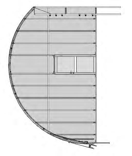
76 75 of 84
77 76 of 84
78 77 of 84
79 78 of 84
80 79 of 84
81 80 of 84
82 NOTE: FRAMING FOR REMAINING END IS THE SAME BUT WITHOUT A DOOR. 81 of of 84

83 PANEL LOCATON DIAGRAM: DOOR END Use part of this panel to cover the small area above the door. See the X above door. 4' x 8' Panel trimmed to size after installation. 4' x 8' Panel trimmed to size after installation. Cut from the remainder of another panel. Install the UV-protected side to the outside. Upper panel is cut from a full 4' x 8' panel. Trim 4' x 8' panel to size after installation. X NOTE: All panels are full 4' x 8' sheets unless otherwise noted above. Seal the bottom edge of the lower panels only using white vent tape. Seal the edge along the end rafter after panel is trimmed to size using foil tape. Ground Level 82 of 84

84 PANEL LOCATON DIAGRAM: NO DOOR 4' x 8' Panel trimmed to size after installation. 4' x 8' Panel trimmed to size after installation. 4' x 8' Panel trimmed to size after installation. 4' x 8' Panel trimmed to size after installation. Cut from the remainder of another panel. Install the UV-protected side to the outside. Each panel is cut from a full 4' x 8' panel. Trim 4' x 8' panel to size after installation. NOTE: All panels are full 4' x 8' sheets unless otherwise noted above. Seal the bottom edge of the lower panels only using white vent tape. Seal the edge along the end rafter after panel is trimmed to size using foil tape. Ground Level 83 of 84
ClearSpan Mini Cold Frames
 ClearSpan Mini Cold Frames Photo may show a different but similar model. 2009 ClearSpan All Rights Reserved. Reproduction is prohibited without permission. STK# DIMENSIONS 105152 6' W x 5' H x 6' L 105153
ClearSpan Mini Grab Bag Shelters
 ClearSpan Mini Grab Bag Shelters Photo may show a different but similar model. Baseboard is not included. 2008 ClearSpan All Rights Reserved. Reproduction is prohibited without permission. STK# DIMENSIONS
ClearSpan Mini Grab Bag Shelters
 ClearSpan Mini Grab Bag Shelters Photo may show a different but similar model. Baseboard is not included. 2008 ClearSpan All Rights Reserved. Reproduction is prohibited without permission. STK# DIMENSIONS
ClearSpan Attached-Style Awning
 ClearSpan Attached-Style Awning Photo may show a different but similar model. 2007 ClearSpan All Rights Reserved. Reproduction is prohibited without permission. Revision date: July 2007ldg STK# DIMENSIONS
WeatherShield Daddy Long Legs Canopy
 WeatherShield Daddy Long Legs Canopy Photo may show a different but similar model. 2010 ClearSpan All Rights Reserved. Reproduction is prohibited without permission. Revision date: 06.210 STK# 1220RV10W10
Moo-Tel Small Animal Hut
 Moo-Tel Small Animal Hut Photo may show a different but similar model. 2010 ClearSpan All Rights Reserved. Reproduction is prohibited without permission. STK# DIMENSIONS 104602 4 6" W x 4' 10" H x 8 2"
GrowSpan Round Cold Frames
 GrowSpan Round Cold Frames Photo may show a different but similar model. 2016 Growers Supply All Rights Reserved. Reproduction is prohibited without permission. STK# DIMENSIONS 103099 12' W x 8' H x 24'
ClearSpan Grab Bag Canopy
 ClearSpan Grab Bag Canopy Photo may show a different but similar model. 2008 ClearSpan All Rights Reserved. Reproduction is prohibited without permission. STK# DIMENSIONS 104385 10 W x 20 L 1 YOU MUST
ClearSpan End Frame Kit 26' Wide x 12' High
 ClearSpan End Frame Kit 26' Wide x 12' High Diagram shows the end frame kit for an end wall without a door. (Door and end panel are purchased separately.) Rafter and struts shown in the above diagram are
WeatherShield Covered Walkway and Connect-A-Building
 WeatherShield Covered Walkway and Connect-A-Building Photo may show a different but similar model. 2014 ClearSpan All Rights Reserved. Reproduction is prohibited without permission. STK# DIMENSIONS 104303
ClearSpan PolyMax Windbreak Wall
 ClearSpan PolyMax Windbreak Wall Photo may show a different but similar model. 2007 ClearSpan All Rights Reserved. Reproduction is prohibited without permission. Revision date: February 2007ldg STK# DIMENSIONS
GrowSpan Gothic Cold Frames
 GrowSpan Gothic Cold Frames Photo may show a different but similar model. 2016 Growers Supply All Rights Reserved. Reproduction is prohibited without permission. STK# DIMENSIONS 106342 30' W x 12' H x
ClearSpan End Frame Kit 30' Wide x 11' High
 ClearSpan End Frame Kit 30' Wide x 11' High Diagram shows the end frame kit for an end wall without a door. (Door and end panel are purchased separately.) Rafter and mounting feet shown in the above diagram
ClearSpan Economy Round Style High Tunnel
 ClearSpan Economy Round Style High Tunnel Photo may show a different but similar model. 2012 ClearSpan All Rights Reserved. Reproduction is prohibited without permission. Revision date: 0112 STK# PB01725R6
ClearSpan Round Style Mini Garage
 ClearSpan Round Style Mini Garage Photo may show a different but similar model. 2008 ClearSpan All Rights Reserved. Reproduction is prohibited without permission. STK# PB01900R4 DIMENSIONS 8' W x 8' H
ClearSpan 20' Wide Free-Standing Building
 ClearSpan 20' Wide Free-Standing Building Photo may show a different but similar model. 2018 ClearSpan All Rights Reserved. Reproduction is prohibited without permission. STK# PB00580R3/R4 PB00582R3/R4
ClearSpan PolyMax Windbreak Wall
 ClearSpan PolyMax Windbreak Wall Photo may show a different but similar model. 2007 ClearSpan All Rights Reserved. Reproduction is prohibited without permission. Revision date: April 2007ldg STK# DIMENSIONS
Premium Solar Star Greenhouse
 Premium Solar Star Greenhouse Assembly Instructions SKU# 104901 2006 ClearSpan All rights reserved. Reproduction without permission is prohibited. Revision date: March 2006g Contact your sales representative
Moo-Tel Calf Hutch CLEARSPAN ANIMAL HOUSING W x 12 L W x 18 L W x 24 L
 Moo-Tel Calf Hutch Photo may show a different but similar model. 2008 ClearSpan All Rights Reserved. Reproduction is prohibited without permission. STK# DIMENSIONS 102852 14 W x 12 L 102853 14 W x 18 L
ClearSpan SolarGuard Round Style Storage Building
 ClearSpan SolarGuard Round Style Storage Building Photo may show a different but similar model. 2009 ClearSpan All Rights Reserved. Reproduction is prohibited without permission. Revision date: 131.09
ClearSpan Majestic Greenhouse Film Roof with Roll-up Sides
 ClearSpan Majestic Greenhouse Film Roof with Roll-up Sides 28' Wide Photo may show a different but similar model. 2009 ClearSpan All Rights Reserved. Reproduction is prohibited without permission. STK#
GrowSpan Round Premium Corrugated Greenhouses
 GrowSpan Round Premium Corrugated Greenhouses Photo may show a different but similar model. 2018 Growers Supply All Rights Reserved. Reproduction is prohibited without permission. STK# DIMENSIONS 104933
GrowSpan Round Premium High Tunnels
 GrowSpan Round Premium High Tunnels Photo may show a different but similar model. 2016 Growers Supply All Rights Reserved. Reproduction is prohibited without permission. STK# PB01680R4 PB01690R4 DIMENSIONS
ClearSpan Majestic Greenhouse Film Roof with Roll-up Sides
 ClearSpan Majestic Greenhouse Film Roof with Roll-up Sides 56' Wide Photo may show a different but similar model. 2009 ClearSpan All Rights Reserved. Reproduction is prohibited without permission. STK#
ClearSpan Open Garages
 ClearSpan Open Garages Photo may show a different but similar model. 2007 ClearSpan All Rights Reserved. Reproduction is prohibited without permission. STK# PB02910R4 DIMENSIONS 18' W x 16' H x 52' L YOU
ClearSpan Front Roll-Up Kit Installation Guide
 ClearSpan Front Roll-Up Kit Installation Guide Roll-up panel opened. Roll-up panel closed. Actual building and panel may differ from what is shown. 2008 ClearSpan All Rights Reserved. Reproduction is prohibited
GrowSpan Estate Pro I Greenhouse
 GrowSpan Estate Pro I Greenhouse Photo may show a different but similar model. 2016 Growers Supply All Rights Reserved. Reproduction is prohibited without permission. STK# DIMENSIONS 104564 11'-8" W x
Assembly Guide for Series 500 Ridge Vent Kits
 Assembly Guide for Series 500 Ridge Vent Kits Photo shows a sample ridge vent as installed on a greenhouse. Actual building and ridge vent length may differ. 2014 ClearSpan All Rights Reserved. Reproduction
GrowSpan Round Pro Greenhouses and Systems
 GrowSpan Round Pro Greenhouses and Systems Photo may show a different but similar model. 2018 Growers Supply All Rights Reserved. Reproduction is prohibited without permission. STK# DIMENSIONS 104836 14
GrowSpan Gothic Premium Greenhouses
 GrowSpan Gothic Premium Greenhouses Photo may show a different but similar model. 2016 Growers Supply All Rights Reserved. Reproduction is prohibited without permission. STK# DIMENSIONS 106209 16' W x
ClearSpan 38' Wide Aircraft Hangar
 ClearSpan 38' Wide Aircraft Hangar Photo may show a model of a different length. 2008 ClearSpan All Rights Reserved. Reproduction is prohibited without permission. STK# DIMENSIONS 107556 38' W x 15' H
ClearSpan Super Moo-Tel Building 26' Wide
 ClearSpan Super Moo-Tel Building 26' Wide Photo may show a different but similar model. 2012 ClearSpan All Rights Reserved. Reproduction is prohibited without permission. STK# PB01500R3/R4 PB01510R3/R4
GrowSpan Gothic HobbyPro Greenhouses
 GrowSpan Gothic HobbyPro Greenhouses Photo may show a different but similar model. 2016 Growers Supply All Rights Reserved. Reproduction is prohibited without permission. STK# DIMENSIONS 104889 16 W x
ClearSpan Majestic Greenhouse Film Roof with Polycarbonate Sides
 ClearSpan Majestic Greenhouse Film Roof with Polycarbonate Sides 84' Wide Photo may show a different but similar model. 2016 ClearSpan All Rights Reserved. Reproduction is prohibited without permission.
ClearSpan 34' Wide Aircraft Hangar
 ClearSpan 34' Wide Aircraft Hangar Photo may show a model of a different length. 2012 ClearSpan All Rights Reserved. Reproduction is prohibited without permission. STK# DIMENSIONS 107554 34' W x 17' 4"
GrowSpan Gothic Pro Greenhouses and Systems
 GrowSpan Gothic Pro Greenhouses and Systems Photo may show a different but similar model. 2017 Growers Supply All Rights Reserved. Reproduction is prohibited without permission. STK# DIMENSIONS 106306
ClearSpan Pro Solar Star Greenhouses
 ClearSpan Pro Solar Star Greenhouses Double-Layer Greenhouse Film Photo may show a building of a different length. Frame is shown with a roll-up side option and customer-supplied baseboards. End wall is
GrowSpan Gothic Pro Greenhouses and Systems
 GrowSpan Gothic Pro Greenhouses and Systems Photo may show a different but similar model. 2016 Growers Supply All Rights Reserved. Reproduction is prohibited without permission. STK# DIMENSIONS 106314
GrowSpan Round Pro Greenhouses and Systems
 GrowSpan Round Pro Greenhouses and Systems Photo may show a different but similar model. 2018 Growers Supply All Rights Reserved. Reproduction is prohibited without permission. STK# DIMENSIONS 104857 26'
ClearSpan Cedar 12' Wide End Frame Kit with Dutch Door
 ClearSpan Cedar 12' Wide End Frame Kit with Dutch Door Photo may show a different but similar model. 2010 ClearSpan All Rights Reserved. Reproduction is prohibited without permission. STK # WIDTH 105366
GrowSpan Gothic Pro Greenhouses and Systems
 GrowSpan Gothic Pro Greenhouses and Systems Photo may show a different but similar model. Film Cover with Film Roll-Up Side Panels 2016 Growers Supply All Rights Reserved. Reproduction is prohibited without
ClearSpan Pro Solar Star High Tunnels
 ClearSpan Pro Solar Star High Tunnels Photo may show a building of a different length. Frame is shown with a roll-up side option and customer-supplied baseboards. End wall is not included and requires
GrowSpan Series 500 Door Kits
 GrowSpan Series 500 Door Kits Double Swinging Door Finished Grade Finished Grade Diagram shows a double-swinging door centered and installed in an end wall frame. The door kit includes materials for the
ClearSpan Pro Solar Star High Tunnels
 ClearSpan Pro Solar Star High Tunnels Photo may show a building of a different length. Frame is shown with a roll-up side option and customer-supplied baseboards. End wall is not included and requires
Sliding Door Kit
 YOU MUST READ THIS DOCUMENT BEFORE YOU BEGIN TO ASSEMBLE THE DOOR KIT. Thank you for purchasing this GrowSpan door kit. When properly assembled and maintained, this product will provide years of reliable
ClearSpan Twin-Wall Polycarbonate End Panel Kit
 ClearSpan Twin-Wall Polycarbonate End Kit 30' Wide & 35' Wide Diagram shows a sample end panel kit for a frame. Actual panel positions and sizes for your end panel package may differ from what is shown.
ClearSpan Corrugated Polycarbonate End Panel Kit
 ClearSpan Corrugated Polycarbonate End Kit 30' Wide & 35' Wide Frame size and layout shown above may differ from actual frame. Photo is used for illustration only. 2010 ClearSpan All Rights Reserved. Reproduction
Sliding Door Kit
 YOU MUST READ THIS DOCUMENT BEFORE YOU BEGIN TO ASSEMBLE THE DOOR KIT. Thank you for purchasing this GrowSpan door kit. When properly assembled and maintained, this product will provide years of reliable
Elite Home-Attached Greenhouse
 Elite Home-Attached Greenhouse Photo may show a greenhouse of a different length. Elite Home-Attached Greenhouse Use these instructions for the following greenhouses: #104711 #104713 #104715 2007 ClearSpan
ClearView Panels Mil 3 Finished Sides with Grommets 1 Hem Side Mil 3 Finished Sides with Grommets 1 Hem Side DESCRIPTION
 ClearView Panels Photo may show a different but similar model. 2006 FarmTek All Rights Reserved. Reproduction is prohibited without permission. Revision date: November 2006rp STK# DESCRIPTION 105659 16
GrowSpan Series 500 Roll-Up Ends
 GrowSpan Series 500 Roll-Up Ends Photo may show a different but similar model. Doorframe materials are not included. 2016 Growers Supply All Rights Reserved. Reproduction is prohibited without permission.
GrowSpan Series 500 Automated Ridge Vent Kits
 GrowSpan Series 500 Automated Ridge Vent Kits Photo shows a sample ridge vent as installed on a greenhouse. Actual building and ridge vent length may differ. 2017 Growers Supply All Rights Reserved. Reproduction
GrowSpan Gothic Pro Greenhouses and Systems
 GrowSpan Gothic Pro Greenhouses and Systems Photo may show a different but similar model. Full Polycarbonate Roof Cover and Ends 2016 Growers Supply All Rights Reserved. Reproduction is prohibited without
6' Wide Premium Greenhouse Benches
 6' Wide Premium Greenhouse Benches Premium Greenhouse Bench with Stationary Top 2015 FarmTek All Rights Reserved. Reproduction is prohibited without permission. STK# DIMENSIONS 112416S6X08 6' W x 3' H
ClearSpan 36' Wide Pony Wall Building
 ClearSpan 36' Wide Pony Wall Building Ground Level Photo may show a model of a different length. Cover is not shown. 2017 ClearSpan All Rights Reserved. Reproduction is prohibited without permission. STK#
Moo-Tel Calf Nurseries
 MOO-TEL CALF NUSEIES Moo-Tel Calf Nurseries Photo may show a different but similar model. 2008 ClearSpan All ights eserved. eproduction is prohibited without permission. evision date: 10.13.08 STK# DIMENSIONS
6' Wide Premium Greenhouse Benches
 6' Wide Premium Greenhouse Benches Premium Greenhouse Bench with Rolling Top 2015 FarmTek All Rights Reserved. Reproduction is prohibited without permission. STK# DIMENSIONS 112416R6X08 6' W x 3' H x 8'
ClearSpan Hydroponic Table Kit
 ClearSpan Hydroponic Table Kit Hydroponic Table Kit (The 109314 (4' x 16') model is shown.) Designed to grow healthy plants without soil using mineral-nutrient solutions. 2009 ClearSpan All Rights Reserved.
GrowSpan 30' Wide Series 500 Tall Greenhouses
 GrowSpan 30' Wide Series 500 Tall Greenhouses Photo may show a building of a different length and style. Frame shown includes optional roll-up sides and customer-supplied baseboards. Building shown is
GrowSpan Heavy-Duty Commercial Cold Frame
 GrowSpan Heavy-Duty Commercial Cold Frame Photo may show a different but similar model. 2018 Growers Supply All Rights Reserved. Reproduction is prohibited without permission. STK# DIMENSIONS 106363 4'
GrowSpan Series 1000 End Wall Cladding Kits
 GrowSpan Series 1000 End Wall Cladding Kits 24' Wide 2017 FarmTek All Rights Reserved. Reproduction is prohibited without permission. Revision date: 02.16.17 STK# GK1EWC24120G 24' Wide (Twin Wall) Important
GrowSpan Single Swinging Door Black-Out Door Kit
 GrowSpan Single Swinging Door Black-Out Door Kit ATTENTION: Door kit includes materials for door only. All other components shown in the diagram above and diagrams throughout this guide are not included
GrowSpan Series 1000 End Wall Cladding Kits
 GrowSpan Series 1000 End Wall Cladding Kits 30' Wide 2017 FarmTek All Rights Reserved. Reproduction is prohibited without permission. Revision date: 02.16.17 STK# GK1EWC30120G 30' Wide (Twin Wall) Important
GrowSpan Series 2000 End Wall Cladding Kits
 GrowSpan Series 2000 End Wall Cladding Kits 35' Wide 2017 FarmTek All Rights Reserved. Reproduction is prohibited without permission. STK# 35' Wide (Twin Wall) Important Information READ THIS DOCUMENT
GrowSpan Series 2000 End Wall Cladding Kits
 GrowSpan Series 2000 End Wall Cladding Kits 20' Wide 2017 FarmTek All Rights Reserved. Reproduction is prohibited without permission. STK# 20' Wide (Twin Wall) Important Information READ THIS DOCUMENT
Twin-Wall Double Swinging Door Kit
 115021 Twin-Wall Double Swinging Kit READ THIS DOCUMENT BEFORE YOU BEGIN Thank you for purchasing this GrowSpan door kit. When properly assembled and maintained, this product will provide years of reliable
GrowSpan 24' Wide Series 500 Tall High Tunnels with Roll-Up Sides
 GrowSpan 24' Wide Series 500 Tall High Tunnels with Roll-Up Sides Photo may show a building of a different length and style. Frame shown includes roll-up sides and customer-supplied baseboards. Actual
GrowSpan Gothic Premium High Tunnels (All H Models)
") GrowSpan Gothic Premium High Tunnels (All H Models) Ground Level Photo may show a different but similar model. These instructions include information for buildings equipped with either drop-down side curtains
GrowSpan Gothic Premium High Tunnels (All H Models) Ground Level Photo may show a different but similar model. These instructions include information for buildings equipped with either drop-down side curtains
GrowSpan 42' Wide Series 500 Tall High Tunnels with Roll-Up Sides
 GrowSpan 42' Wide Series 500 Tall High Tunnels with Roll-Up Sides Photo may show a building of a different length and style. Frame shown includes drop-down sides and customersupplied baseboards. Actual
WHITE - Accessories. Series 500 Greenhouse Kit w/blackout System, Ventilation & Evaporative Cooling
 Series 500 Greenhouse Kit w/blackout System, Ventilation & Evaporative Cooling WHITE - Accessories 2016 Growers Supply All Rights Reserved. Reproduction is prohibited without permission. Revision date:
Double Truss Shelter Model# SST W9.14xL14.2xH4.88m Assembly Instructions
 Double Truss Shelter Model# SST304716 W9.14xL14.2xH4.88m Assembly Instructions Page 1 RECOMMENDED TOOLS Equipment List Speed Wrench 22#.23#.24# Hammer (30lb) Rope (12#) Long Tape (50m) Hammer Drill*1 Lifter*2
GREEN - Main Frame Film Cladding
 Series 500 Greenhouse Kit w/blackout System GREEN - Main Frame Film Cladding 2017 Growers Supply All Rights Reserved. Reproduction is prohibited without permission. GB30_GREEN 30' Wide Series 500 Main
ClearSpan 30' Wide Econoline Storage Building
 CLEASPAN POLY BUILDINGS ClearSpan 30' Wide Econoline Storage Building Photo may show a model of a different length. 2008 ClearSpan All ights eserved. eproduction is prohibited without permission. evision
ClearSpan 30' Wide Pony Wall Building
 CLEASPAN POLY BUILDINGS ClearSpan 30' Wide Pony Wall Building Photo may show a model of a different length. 2015 ClearSpan All ights eserved. eproduction is prohibited without permission. evision date:
Twin-Wall Double Swinging Door Kit
 105105 Twin-Wall Double Swinging Kit YOU MUST READ THIS DOCUMENT BEFORE YOU BEGIN TO ASSEMBLE THE DOOR KIT. Thank you for purchasing this GrowSpan door kit. When properly assembled and maintained, this
Breathable Wall Light Traps & Blackout Fan & Shutter Kits
 Breathable Wall Light Traps & Blackout Fan & Shutter Kits 2017 Growers Supply All Rights Reserved. Reproduction is prohibited without permission. Maintain controlled airflow without sacrificing blackout
RED - Main Frame. Series 500 Greenhouse Kit w/blackout System, Ventilation & Evaporative Cooling
 Series 500 Greenhouse Kit w/blackout System, Ventilation & Evaporative Cooling RED - Main Frame 2017 Growers Supply All Rights Reserved. Reproduction is prohibited without permission. Revision date: 03.08.17
ClearSpan Twist-of-the-Wrist Assembly Instructions
 ClearSpan Twist-of-the-Wrist Assembly Instructions Curved-Wall for Roll-Up Side Flat-Wall for Curtain Application 2008 ClearSpan All Rights Reserved. Reproduction is prohibited without permission. Revision
Assembly Guide for Over-The-Top Blackout System
 Assembly Guide for Over-The-Top Blackout System ATTENTION: This guide describes the assembly and installation of an over-the-top roll-up curtain system. The design flexibility of this curtain system allows
Blackout Fan Kits with Breathable Wall Light Traps
 Blackout Fan Kits with Breathable Wall Light Traps 2018 Growers Supply All Rights Reserved. Reproduction is prohibited without permission. Maintain controlled airflow without sacrificing blackout environments.
EZ-Grow Professional Greenhouse Bench
 EZ-Grow Professional Greenhouse Bench Photo may be of a different but similar model. (Bench shown includes the expanded metal top; additional purchase is required for some models.) 2010 ClearSpan All Rights
ClearSpan Pro Solar Star Greenhouse
 ClearSpan Pro Solar Star Greenhouse Corrugated Polycarbonate Photo may show a building of a different length. Frame is shown with an option end wall and customersupplied baseboards. End wall is not included
Mini Brute Feed Bunks
 Mini Brute Feed Bunks All Rights Reserved. Reproduction is prohibited without permission. SKU# DIMENSIONS 108260 19" W x 8' L 1 READ THIS DOCUMENT BEFORE YOU BEGIN TO ASSEMBLE THE FEED BUNK. Thank you
Blackout Fan Kits with Breathable Wall Light Traps
 Blackout Fan Kits with Breathable Wall Light Traps 2018 Growers Supply All Rights Reserved. Reproduction is prohibited without permission. Maintain controlled airflow without sacrificing blackout environments.
ClearSpan Raised Bed Kits
 ClearSpan Raised Bed Kits Photo may show a different but similar model. 2010 ClearSpan All Rights Reserved. Reproduction is prohibited without permission. STK# DIMENSIONS TIERS 106457 4' W x 8' L 1 106458
Blackout Fan Kit with Breathable Wall Light Trap
 Blackout Fan Kit with Breathable Wall Light Trap 2018 Growers Supply All Rights Reserved. Reproduction is prohibited without permission. Maintain controlled airflow without sacrificing blackout environments.
Anchor Kit Installation Guide
 Anchor Kit 105587 Installation Guide Use the following photos as guides to identify the rafter leg pipe diameter of your ClearSpan shelter. Install the anchor kit brackets as shown in the photos below.
111628W FodderPro 2.0 Full Feed System Wall Mount
 111628W FodderPro 2.0 Full Feed System Wall Mount "...grow your own nutrient-rich fodder..." WALL End View Shows Supply Manifold and Channels Side View with Channels and Manifolds Installed 2015 FarmTek
UNIVERSAL ASSEMBLY INSTRUCTIONS FOR VERSATUBE GARAGE BUILDINGS
 UNIVERSAL ASSEMBLY INSTRUCTIONS FOR VERSATUBE GARAGE BUILDINGS SINGLE DOOR GARAGE AVAILABLE IN 12, 20, 24 AND 30 WIDTHS DOUBLE DOOR GARAGE AVAILABLE IN 24 AND 30 WIDTHS Our unique assembly process quickly
Insect Screen for Exhaust Fans
 Insect Screen for Exhaust Fans Actual fan and screen kit may differ. 2016 Growers Supply All Rights Reserved. Reproduction is prohibited without permission. STK# 115106F 115107F 115108F DIMENSIONS 24"
INSTALLATION INSTRUCTIONS LS X 12-2 X 7 1/2 FRAME LOAFING SHED
 INSTALLATION INSTRUCTIONS LS-12 12 X 12-2 X 7 1/2 FRAME ACTUAL FRAME BASE SIZE: 12 X 12-2 LOAFING SHED Our unique assembly process quickly transforms the individual pieces into a finished structure that
HydroCycle 4" Pro NFT Lettuce Systems
 HydroCycle 4" Pro NFT Lettuce Systems 110830 Hydroponic Table Kit* Designed to grow healthy plants without soil using mineral-nutrient solutions. 2016 Growers Supply All Rights Reserved. Reproduction is
CONTENTS TOOL LIST U P S I D E I N N O V A T I O N S, L L C RAMP AND STEP SYSTEM ASSEMBLY INSTRUCTIONS. Revised: June 2013
 U P S I D E I N N O V A T I O N S, L L C RAMP AND STEP SYSTEM ASSEMBLY INSTRUCTIONS TOOL LIST Required Tools: - Reciprocating Saw with Metal Cutting Blade - Drill - 7/16 Drill Bit for Metal Drilling -
Roof Only Lean-to Instruction Manual
 Roof Only Lean-to Instruction Manual for 10 x 20 2 x 8 /10 6 covers Our unique assembly process quickly transforms the individual pieces into a finished structure that will give you a lifetime of service.
INSTALLATION INSTRUCTIONS LS X 12-2 X 7 1/2 FRAME LOAFING SHED
 INSTALLATION INSTRUCTIONS LS-24 24 X 12-2 X 7 1/2 FRAME ACTUAL FRAME BASE SIZE: 24 X 12-2 LOAFING SHED Our unique assembly process quickly transforms the individual pieces into a finished structure that
7 X 10 X 6 SHELTER 7 X 16 X 6 SHELTER 12 X 10 X 6 SHELTER 12 X 16 X 6 SHELTER
 ASSEMBLY INSTRUCTIONS FOR 7 X 10 X 6 AND 7 X 16 X 6 ATV SPORT SHELTER ACTUAL FRAME SIZES: 7 X 9-1 1/2 X 6 AND 7 X 13-7 1/2 X 6 AND 12 X 10 X 6 AND 12 X 16 X 6 ATV SPORT SHELTER ACTUAL FRAME SIZES: 12 X
Storage Master. Shed Row. Poly Buildings
 Storage Master Shed Row Poly Buildings Instructions Manual Building #104598 2005 ClearSpan All rights reserved. Reproduction prohibited without permission. Rev: 24 February 2005 2 PARTS IDENTIFICATION
UNIVERSAL INSTALLATION INSTRUCTIONS FOR CARPORTS
 UNIVERSAL INSTALLATION INSTRUCTIONS FOR CARPORTS FRAME SIZES: WIDTH: 10, 12, 14, 16, 18, 20, 24, AND 30 ON CENTER FRAME SPACING: 4, 4 1/2, AND 5 FRAME LENGTH: 4 ON CENTER 20-2, 4 1/2 ON CENTER 18 AND 5
INSTALLATION INSTRUCTIONS LS X 12-2 X 7 1/2 FRAME LOAFING SHED
 INSTALLATION INSTRUCTIONS LS-30 30 X 12-2 X 7 1/2 FRAME ACTUAL FRAME BASE SIZE: 30 X 12-2 LOAFING SHED Our unique assembly process quickly transforms the individual pieces into a finished structure that
Premium Low-Profile Benches for Dutch Buckets Single Row
 Premium Low-Profile Benches for Dutch Buckets Single Row 2016 Growers Supply All Rights Reserved. Reproduction is prohibited without permission. STK# 115050 12" x 72" 115051 12" x 144" 1 Important Information