An integrated system to design machine layouts for modular special purpose machines
|
|
|
- Maud Mosley
- 5 years ago
- Views:
Transcription
1 Edith Cowan University Research Online Theses: Doctorates and Masters Theses 2018 An integrated system to design machine layouts for modular special purpose machines Uday Hameed Farhan Edith Cowan University Recommended Citation Farhan, U. H. (2018). An integrated system to design machine layouts for modular special purpose machines. Retrieved from This Thesis is posted at Research Online.
2 Edith Cowan University Copyright Warning You may print or download ONE copy of this document for the purpose of your own research or study. The University does not authorize you to copy, communicate or otherwise make available electronically to any other person any copyright material contained on this site. You are reminded of the following: Copyright owners are entitled to take legal action against persons who infringe their copyright. A reproduction of material that is protected by copyright may be a copyright infringement. Where the reproduction of such material is done without attribution of authorship, with false attribution of authorship or the authorship is treated in a derogatory manner, this may be a breach of the author s moral rights contained in Part IX of the Copyright Act 1968 (Cth). Courts have the power to impose a wide range of civil and criminal sanctions for infringement of copyright, infringement of moral rights and other offences under the Copyright Act 1968 (Cth). Higher penalties may apply, and higher damages may be awarded, for offences and infringements involving the conversion of material into digital or electronic form.
3 An integrated system to design machine layouts for modular special purpose machines This thesis is presented for the degree of Doctor of Philosophy Uday Hameed FARHAN Edith Cowan University School of Engineering 2018
4 USE OF THESIS The Use of Thesis statement is not included in this version of the thesis.
5 ABSTRACT This thesis introduces the development of an integrated system for the design of layouts for special purpose machines (SPMs). SPMs are capable of performing several machining operations (such as drilling, milling, and tapping) at the same time. They consist of elements that can be arranged in different layouts. Whilst this is a unique feature that makes SPMs modular, a high level of knowledge and experience is required to rearrange the SPM elements in different configurations, and also to select appropriate SPM elements when product demand changes and new layouts are required. In this research, an integrated system for SPM layout design was developed by considering the following components: an expert system tool, an assembly modelling approach for SPM layouts, an artificial intelligence tool, and a CAD design environment. SolidWorks was used as the 3D CAD environment. VisiRule was used as the expert system tool to make decisions about the selection of SPM elements. An assembly modelling approach was developed with an SPM database using a linked list structure and assembly relationships graph. A case-based reasoning (CBR) approach was developed and applied to automate the selection of SPM layouts. These components were integrated using application programing interface (API) features and Visual Basic programming language. The outcome of the application of the novel approach that was developed in this thesis is reducing the steps for the assembly process of the SPM elements and reducing the time for designing SPM layouts. As a result, only one step is required to assemble any two SPM elements and the time for the selection process of SPM layouts is reduced by approximately 75% compared to the traditional processes. The integrated system developed in this thesis will help engineers in design and manufacturing fields to design SPM layouts in a more time-effective manner. iii
6 DECLARATION I certify that this thesis does not, to the best of my knowledge and belief: (i) (ii) (iii) incorporate without acknowledgment any material previously submitted for a degree or diploma in any institution of higher education; contain any material previously published or written by another person except where due reference is made in the text; or contain any defamatory material I also grant permission for the Library at Edith Cowan University to make duplicate copies of my thesis as required. Signature:.. Date:...6/5/ iv
7 ACKNOWLEDGEMENTS Firstly, I would like to thank my principal supervisor Dr Majid Rad and my associate supervisor A/Prof Adam Osseiran. I greatly appreciate their feedback and time, despite their academic commitments, regarding my work over the three years that I have spent completing my PhD and this thesis. In particular, I owe my deepest gratitude to my father for his support over the three years of my PhD, and for his understanding for being away with my family from home for all these years. His encouragement has brought this thesis to complete, and I dedicate this work to him. I am indebted to my wife and children for their inspiration and patience over the three years of my PhD. It was definitely a very hard decision to undertake this PhD and bring my family to a very new country and life. I thank them for standing beside me throughout my study, and for being my inspiration and motivation to complete this thesis. I hope this will help to start a new future for us. I would like to thank Dr Helen Renwick for her help in checking and correcting the writing of my thesis. I would like also to thank ECU scholarships office and Graduate Research School for the support during undertaking my PhD. Finally, I would like to thank all my friends in Australia and back home for the help and support that they provided to us in order to settle in and overcome the many problems that we have faced during the past three years. v
8 List of publications On the basis of the outcome of this research, the following papers have been published: Farhan, U., Tolouei-Rad, M. & Osseiran, A. Indexing and retrieval using case-based reasoning in special purpose machine designs, The International Journal of Advanced Manufacturing Technology, Volume 92, Issue 5 8, pp Print ISSN Online ISSN Publisher: Springer London. DOI: Uday Hameed Farhan, Majid Tolouei-Rad, Adam Osseiran. "Use of AHP in decision-making for machine tool configurations", Journal of Manufacturing Technology Management, Vol. 27 Issue: 6, pp Publisher: Emerald Group Publishing Limited. DOI: Uday Hameed Farhan, Majid Tolouei-Rad, Adam Osseiran, (2018) "Assembly modelling approach for special purpose machines", Assembly Automation, Vol. 38 Issue: 2, pp , Uday Hameed Farhan, Majid Tolouei-Rad, Adam Osseiran, (2017) Enhancing the reconfigurability of special purpose machine tools using mechanical module interfaces, Journal of Achievements in Materials and Manufacturing Engineering. Vol. 2 Issue: 84, pp.56-66, DOI: / vi
9 Table of Contents 1. INTRODUCTION Problem Statement Research Questions Aims and Significance Organisation of Thesis LITERATURE REVIEW AND BACKGROUND Manufacturing Systems Dedicated manufacturing systems Flexible manufacturing systems Reconfigurable manufacturing systems Simulation and assembly modelling of manufacturing systems Automated design of manufacturing systems Genetic algorithm Fuzzy logic Case-based reasoning Artificial neural networks Rule-based expert systems Analytical hierarchy process (AHP) The principles of SPMs The basic units of SPMs The Concept of SPMs Drilling units Tapping units CNC units Multiple spindle heads Tool holders Assembly components Machine components vii
10 2.5 Integration methods The computer programming platform The 3D modelling environment The Database Discussion of literature review Identified problems for SPMs Literature support to solve SPM problems The novel approach THE DEVELOPMENT OF SPM KNOWLEDGE-BASE Selecting the number of SPM workstations Creating the knowledge-base Drilling machining operations Selecting the machining units for multiple holes Machining two holes in SPMs Machining three-hole patterns in SPMs Drilling four-hole patterns in SPMs Tapping machining operations Machining one tap in SPMs Machining two taps in SPMs Machining three taps in SPMs Machining four taps in SPMs Selecting the assembly and machine components Horizontal and vertical supports Implementation of the expert system tool (VisiRule) Summary ASSEMBLY MODELLING AND AUTOMATION FOR SPMS Building the SPM elements database Microsoft Access database for SPMs The design library of SPM elements viii
11 4.2 Assembly relationship graph Mating conditions identification and representation The framework of the assembly approach for SPMs Implementation and Results Summary AUTOMATION OF LAYOUT SELECTION FOR SPMS Case-based reasoning for SPMs The indexing system Retrieval Cases Representation of the case-base The organisation of the case-base The implementation of the CBR approach The integration process Add-in project development Results and discussion Standard deisng process The new integrated system Summary FURTHER TECHNIQUES IN SPM DESIGN AHP for SPMs Implementation of AHP for SPMs Enhancing the reconfigurability of SPMs The proposed solution The design concept Performance criteria for the proposed adapter Summary CONCLUSIONS AND FUTURE WORK Research outcomes and contributions ix
12 7.2 Future Work REFERENCES APPENDICES Cutting information and parameters for SPMs Additional rules of drilling one and multiple holes in SPMs Additional rules for tapping one and multiple holes in SPMs Part of the generated code in VisiRule Additional charts developed in VisiRule The design information for a half-collar workpiece Additional figures for the SPM database Part of the code for the Add-In project for the integration process x
13 LIST OF FIGURES Figure 2-1. A structure of CIM in manufacturing [1] Figure 2-2. (a) A traditional lathe [13], and (b) an automated machining system [14] Figure 2-3. A Flexible manufacturing system [1] Figure 2-4. An example of RMS [20] Figure 2-5. Simulation of a produced part in CNC machining tools [26] Figure 2-6. A methodology using CBR for fixture design [70] Figure 2-7. An ANN structure [53] Figure 2-8. The development of an expert system [54] Figure 2-9. An industrial robot guided by an expert system [1] Figure A standard hierarchy structure for a decision problem elements Figure Incomplete hierarchy structure for decision problem elements Figure The comparison of three types of machine tools [3] Figure An example of an SPM [124] Figure 3-1. The contribution of the collected information in building a knowledge base Figure 3-2. The process of implementing the developed knowledge-base with software Figure 3-3. The development of the SPM knowledge-base Figure 3-4. A designed cylinder head for motorcycles Figure 3-5. The workstations that are needed to perform tapping and reaming for the selected workpiece Figure 3-6. Two sequences for the same machining operations for the selected workpiece Figure 3-7. The process of selecting the number of workstations for the drilling operation in SPMs xi
14 Figure 3-8. The selection process of the number of workstations required in SPMs Figure 3-9. Different hole configurations on one and/or two surfaces on a workpiece; (a), (b), (c), and (d) illustrate different numbers of holes in the same diameters, while (e), (f), (g), and (h) show several numbers of holes of different diameters on one and/or two surfaces Figure The process of determining the number of workstations for drilling on one surface Figure The process for defining the number of workstations for drilling on two surfaces Figure Examples of cast iron applications: (a) a cylinder block [168], (b) a cylinder head [169], (c) a gearbox case [170], (d) a bearing housing [171] Figure Examples of steel applications: (a) a wheel hub [172], (b) a CV joint [173], (c) a door hinge [174], (d) a flange [175] Figure Examples of aluminium products: (a) and (b) aerospace applications [176, 177], (c) and (d) electrical applications [177, 178] Figure Examples of brass products: (a) an electrical air valve [179], (b) electrical brass terminals [180], (c) a brass gate valve [181], (d) plumbing brass fittings [182] Figure Examples of plastics products: (a) PVC valves [183], (b) a plastic housing for automobiles applications [184], (c) a plastic box for electrical applications [185] Figure Two holes with spacing range (s) Figure The adjustable multiple spindle heads MH20 and the fixed multiple spindle heads MHF [124] Figure Straight line three-hole pattern Figure Staggered three-hole pattern Figure Adjustable multiple spindle heads MH 33 and MH 30 [124] Figure Adjustable multiple spindle head MH40 [124] Figure Four-hole pattern and the spacing range S1 and S Figure (a) a GEM tapping unit, (b) GSX tapping attachment [124] Figure The process of defining the number of workstations for tapping on one and two surfaces xii
15 Figure (a) A workpiece with one machine surface and one tap [187], (b) a workpiece with one machined surface and two taps in the same size [188] Figure (a) A workpiece with one machined surface and two taps in different sizes [189], (b) a workpiece with four taps on the top surface and two taps on the side surface [190] Figure Two taps with spacing range (S) Figure Straight line pattern of three M6 taps with maximum spacing range S2 and minimum spacing range S Figure Staggered pattern for three M6 taps with maximum spacing range S2 and minimum spacing range S Figure Four-tap pattern with maximum and minimum distances S2 and S1 between the taps Figure (a) A machining unit with a horizontal support, (b) a machining unit with a vertical support [124] Figure (a) Base plates, (b) slide blocks [124] Figure Calculating the spindle height for a specific machining operation Figure The distance from the spindle to the bottom surface of the machining unit [124] Figure A workpiece with a hole feature on the side surface 50 mm from the bottom surface Figure Calculating ht value which is equal to the sum of the height of the workpiece (h3) and the height of the RT (h) Figure A MONO machining unit - BEM 6 -, (a) without a spindle head and, (b) with a multiple spindle head [124] Figure An SPM frame consisting of with angle supports and VBG components. The zero level is the top surface of the angle support [124] Figure Initial stages of a flowchart in VisiRule Figure Mapping the rules as question and expression boxes in VisiRule Figure The start window with the generated code Figure A designed workpiece (half-collar) xiii
16 Figure Examples of the screen captures in VisiRule Figure The result of the implementation of the SPM knowledge-base in VisiRule Figure 4-1. Geometric and Assembly Modellers [191] Figure 4-2. An assembly tree illustrating the connection between parts and subassemblies [191] Figure 4-3. The eight assembly features Figure 4-4. Supporting and supported faces for SPM elements Figure 4-5. The categories and classifications of SPM elements Figure 4-6. A general list data structure Figure 4-7. A data structure representing an BEM 6 element Figure 4-8. A table for function elements in the SPM database Figure 4-9. Creating the SPM folders in the design library in SolidWorks Figure (a) A machine base designed in SolidWorks and (b) adding this element to the design library Figure The assembly relationships graph (ARG) Figure Different SPM elements designed and stored in the design library Figure The developed ARG of SPM elements Figure Three DOF, two linear and one rotational, between two SPM elements F and V Figure Three definitions of the mark for three different faces, one plane and two cylindrical Figure (a) The against condition between two faces, and (b) the fits mating condition between two elements. Element 2 is a pin with the cylindrical face and is assembled to element 1 by the fits condition with the hole Figure An example to illustrate the application of the contact condition with the against condition between two parts Figure The four cases for mating conditions xiv
17 Figure The algorithm for identifying mating conditions for SPM elements Figure The assembly sequence reasoning mechanism for SPMs Figure The framework of the developed assembly modelling approach for SPMs Figure The assembly graph for the selected SPM elements Figure The angle support (A) is selected and inserted in the assembly Figure Element A still able to move along x and y directions and rotate about z after applying the constraint Figure The elements M, A, H, and F are assembled in by applying the developed assembly sequence Figure The design of the selected workpiece Figure The assembly graph of the SPM elements that are required to complete the layout for machining the workpiece shown in Figure Figure The complete SPM layout for the selected workpiece Figure A designed cylinder of motorbike engines with holes and taps required for machining by an SPM Figure The complete SPM layout after applying the assembly approach for the selected workpiece shown in Figure The layout has four stations as numbered to perform the required machining operations Figure Different workpieces and their SPM layouts, which were assembled by the proposed approach Figure Assembly time for various workpieces in the traditional process versus assembly time in the proposed approach Figure 5-1. The framework of the integrated system for SPMs Figure 5-2. (a) The overall CBR model, and (b) the steps of recall process Figure 5-3. A complete algorithm for the first level of the retrieval process for SPMs Figure 5-4. A complete algorithm for the second level of the retrieval process for SPMs with a calculation of the total similarity value Figure 5-5. An example of the representation of a case content in the casebase xv
18 Figure 5-6. The organization of the stored cases in the case-base Figure 5-7. A target workpiece Figure 5-8. The code pattern generated by the developed indexing system. Each number refers to a specific attribute of the target workpiece Figure 5-9. The five closest cases to the target workpiece from the first retrieval process Figure The suggested SPM solution of Case-07. The numbers are references to the stations of the layout Figure The modified solution for the target workpiece Figure An example of a mechanical workpiece used in a hydraulic mechanism [206] Figure The suggested solution of the SPM design for the Case Figure The modified solution of the SPM design for the target workpiece Figure A cylinder head for motorcycle engine [207] Figure Case-09 in the case-base Figure The solution for case Figure The modified solution of Case Figure A motorbike engine cylinder design with holes and taps required for machining by an SPM Figure The modified solution for the fourth workpiece Figure The new menu, SPM system, and the sub-menus the in SolidWorks environment Figure SPM indexing window Figure The result of the first level retrieval Figure The result of the second retrieval process and the SPM solution suggested by the system Figure Selecting MONO drilling units from the SPM database Figure Selecting the vertical support elements Figure Selecting the machine base element xvi
19 Figure The time saving achieved by the system developed in comparison to the standard SPM design process Figure 6-1. Two basic SPM configurations: (a) the workpiece is fixed in a position and manufactured by the machining units, (b) the workpiece is transferred from a station to another to perform several machining operations Figure 6-2. (a) The SPB workpiece transfer and (b) the DSC workpiece transfer [124] Figure 6-3. A special design of SPMs [166] Figure 6-4. The decision hierarchy for the identified elements for the given criteria, sub-criteria, and alternatives Figure 6-5. The design for the selected workpiece (half-collar) Figure 6-6. The weights of alternatives Figure 6-7. Other scenarios from the AHP model for the same workpiece; (a) one machined workpiece with no transfer (fixed), and (b) two specialsize workpieces machined at each station Figure 6-8. The entry window of the AHP model for the required criteria Figure 6-9. The results window for the first scenario after the pairwise compression Figure The construction of SPMs and some possible configurations Figure The three levels of replacement for SPMs Figure (a) The DCS system and its MF chucks, and (b) the SPB system and its ML chucks Figure Both SPB and DSC systems can be combined in one platform to accommodate both types of chucks without the need to change the whole system Figure The original DSC Figure (a) A quick-change module, and (b) a clamping pallet Figure The attachment of the adapter to four stations SPM and possible configurations Figure (a) The modified DSC workpiece transfer, and (b) the modified clamping pallet xvii
20 Figure A model shows how DOF are restricted for the adapter (i.e. the quick-change module and the clamping pallet) Figure A complete arrangement of the modified DSC, clamping pallets, and MF chucks for 4 station SPMs Figure The original arrangement for the DSC and MF chucks Figure Natural frequencies and shape modes for the clamping pallet xviii
21 LIST OF TABLES Table 2-1. The features of the three manufacturing systems Table 2-2. The scale for pairwise comparison in AHP Table 2-3. Average RI values Table 2-4. The time required for machining a part in three different machining systems [97] Table 4-1. The DOF of SPM elements as determined from the ARG model. The elements are referred as the first letter of their names as shown in Figure Table 4-2. Examples of mating conditions between some of the SPM elements Table 4-3. The relationships matrix for the SPM elements shown in Figure Table 4-4. The relationship matrix of the SPM elements Table 5-1. The indexing for the workpiece attributes Table 5-2. The indexing for the machining attributes Table 5-3. Information of the target workpiece Table 5-4. The value of the threshold for the retrieved cases Table 5-5. Defining the number of matched attributes for the stored cases with regard to the first six digits of the target workpiece code Table 5-6. The values of SIMt of the retrieved cases Table 6-1. The comparison matrix for criteria Table 6-2. The normalised matrix for criteria Table 6-3. The comparison matrix for sub-criteria with respect to workpiece transfer Table 6-4. The comparison matrix for sub-criteria with respect to operation type Table 6-5. The local and global weights for the sub-criteria Table 6-6. The comparison matrix for the alternatives with regard to S xix
22 Table 6-7. The priorities from the comparison matrices of the alternatives with regard to the sub-criteria Table 6-8. The final weights of the alternatives from the synthesis process xx
23 LIST OF ABBREVIATIONS Common abbreviations that have been used in this thesis are listed below: CAD: Computer aided design CAM: Computer aided manufacturing SPMs: Special purpose machines AI: Artificial intelligence CBR: case-based reasoning AHP: analytical hierarchy process API: application programming interface SIM: similarity between attributes in CBR MRR: material removal rate CNC: Computer Numerical Control xxi
24 In the memory of my mother. xxii
25 Chapter One
26 Introduction 1. Introduction 1.1 Problem Statement Demand for new products has increased as a result of global competition, and as a result, manufacturing companies need to apply new strategies and methods to enable them to face unpredictable changes in product design. Traditional manufacturing systems were inflexible and the production of high-quality products required a high level of skills. Therefore, high production costs were associated with the use of traditional systems. In order to reduce production costs, it was important to improve the flexibility and efficiency of the manufacturing systems, and that was achieved by applying automation technologies to many aspects of manufacturing [1]. One of the applications of automation is flexible manufacturing systems (FMSs), which use computer numerical control (CNC) machine tools. These systems were developed to produce a variety of parts with high flexibility. However, when large numbers of products are needed, FMSs are expensive. Reconfigurable manufacturing systems (RMSs) have been also designed and applied to produce a group family of products [2]. Another area of automation is SPMs, which are machine tools that can be used to manufacture parts in a high production rate [3]. The main benefits of SPMs are increasing the accuracy of the product and reducing labour and production times. The use of these machine tools is still limited in industry because knowledge of this type of machine is not yet fully developed and is still developing. Computer technology has been developed rapidly and this has had a direct impact on the automation of manufacturing systems, and artificial intelligence (AI) technology has been applied to automate the design and assembly process of manufacturing systems [4]. While different approaches and AI methods have been implemented, expert systems have been used most often to build the engineering knowledge required to automate the design process in manufacturing systems. Modelling by computers has also become necessary to improve the 2
27 Introduction design phase and to define possible errors in manufacturing systems. Modelling is important in designing and simulating different engineering systems [5], and many software packages have been developed to build efficient modelling systems for automation and simulation purposes. However, there appears to be little knowledge and research on building integrated and automated applications for manufacturing systems, particularly for SPMs. This knowledge is needed to rearrange the SPM elements in different configurations when the demand for products is changed. The response to this change must be accomplished quickly by selecting the required SPM elements and defining the most suitable SPM layouts to achieve better productivity. In addition, each part or workpiece has specific features and specifications: identifying the feasible SPM layouts can be time-consuming, costly, and complex. To address this issue, this research developed an integrated system using appropriate AI methods and a CAD software program. The system that emerged from this work provides further support for the use of SPMs in manufacturing and facilitated the automatic selection of SPM elements and layouts. 1.2 Research Questions 1- Engineering knowledge is a crucial factor in developing automated design systems. Expert systems have been used to implement this knowledge due to their unique features. However, there is a lack of knowledge around SPMs. A key question, therefore, is how can SPM knowledge be developed, and how can this knowledge be used and implemented in order to automate the selection of SPM elements? 2- Assembly relationships are an important measure when performing the assembly process for machine components. 3D CAD software programs have tools, assembly features, and 3D modelling capabilities which are able to assemble different machine components. How can the assembly relationships for the SPM elements be defined? How can these defined 3
28 Introduction assembly relationships be used with 3D CAD software programs to accelerate the assembly process of SPM layouts and reduce assembly time? 3- Automation is an important technique that has been applied to manufacturing systems. This technique can be used to improve the design and assembly processes of manufacturing systems. How can the selection of SPM layouts and elements be automated and what methods can be implemented? 4- The integration of different techniques and software programs can bring many benefits for design activities and make them faster and compact. How can different components of the SPM layouts design system be integrated? 1.3 Aims and Significance Designing feasible SPM layouts includes the selection of the necessary SPM elements, and it is important that this selection process is automated to reduce the design time. Therefore, the objectives of this research are as below: (1) To develop a knowledge-base for SPMs and implement it in an expert system tool. Developing an SPM knowledge-base is important in order to address the domain knowledge for SPMs. This helps engineers and designers to select the appropriate SPM elements for different machining operations. VisiRule expert system is used in this work as a decision-making tool to implement the developed SPMs knowledge-base. This is because VisiRule has unique features enabling it to implement different types of rules and generate a code for the knowledge-base developed in this work. This code can be used with other applications and software programs. (2) To develop an assembly modelling approach for SPMs and implement it in SolidWorks. This includes creating an SPM database and a design library. 4
29 Introduction Developing an assembly modelling approach for SPMs helps to identify the assembly relationships for the SPM elements. These relationships are then implemented using application programming interface (API) features in SolidWorks in order to automate the assembly process of the SPM elements. This reduces the assembly time for the SPM layouts. (3) To develop an indexing and retrieval approach for SPMs using casebased reasoning (CBR). Developing this approach helps in the selection of suitable SPM layouts by suggesting similar solutions for new target workpieces. This leads to reducing the overall design time for SPM layouts. (4) To integrate the above components in the SolidWorks environment. The importance of this integration is that it makes these components accessible in one environment. This enables the design process of the SPM layouts to be completed quickly and effectively. The aim of the combination of these objectives is to develop an integrated system that will support the selection of feasible SPM layouts. In addition to these objectives, this work considers other techniques that can also be investigated regarding the determination of SPM configurations and the enhancement of the SPM reconfigurability degree. 1.4 Organisation of Thesis This thesis is divided into seven chapters. Chapter 1 provides the general introduction, and the literature review for this research is presented in Chapter 2. Chapter 3 presents the development of the SPM knowledge-base and explains how it can be coded by VisiRule. The assembly modelling approach of SPMs is explained in Chapter 4, which includes a full description of its application. Chapter 5 presents the development of the indexing and retrieval approach and how it can be applied to SPMs. Chapter 5 also explains the integration of the 5
30 Introduction main components developed in this work with the SolidWorks environment. Other techniques that can be used in SPMs are investigated and discussed in Chapter 6, which gives a description of an AHP method to be applied to SPMs, in addition to a proposed design of a mechanical adapter that can be used in SPMs. Conclusions and suggestions for future work are given in Chapter 7. 6
31 Chapter Two
32 Literature review 2. Literature Review and Background The use of new technologies including computer assisted technologies has led to a rapid development in manufacturing systems in order to enhance productivity. Computer technology has brought many benefits, has helped engineers and manufacturers to face the demand of high productivity. Many design and manufacturing activities have been automated or guided by computers, and this has brought great flexibility and saved time and cost. This chapter provides a description of manufacturing systems and discusses their advantages and disadvantages. The chapter discusses simulation and assembly modelling and investigate AI methods for automated design of manufacturing systems. Background information about SPMs is given in Section 2.4, along with their principles and features. Section 2.5 investigates integration methods for automated design and assembly processes. The final section (Section 2.6) integrates the information and methods discussed in this chapter to provide a context of this research, and a descriptive approach is outlined. Computer aided manufacturing (CAM) can be defined as the use of computer technology in an effective way in manufacturing to improve productivity [6]. Computers are employed in direct and indirect manufacturing processes. The former involve CNC, flexible manufacturing systems (FMS), robotics, and automated manufacturing cells [7]. The latter involve computer-aided process planning (CAPP), computer-aided facility planning and design, and manufacturing process planning. In addition, computer technology is used to support the decision-making process employing AI and expert systems in manufacturing. As a result, CAM has played an important role in increasing the productivity in manufacturing systems. A large number of functions, from FMS to machine control, are included in CAM, which is part of computer integrated manufacturing (CIM). CIM integrates computer technology into all aspects of manufacturing organisation such as product design, process planning, distribution, production, operation, and management [1]. Figure 2-1 illustrates an example of CIM structure. 8
33 Literature review Computer aided design (CAD) can be described as the use of computers to facilitate the design process for models and drawings, and it has been employed in many applications for electric and electronic circuits, architectural design, the animation of movies, fashion design, and design of mechanical systems [7-9]. CAD was initially developed in the 1960s and most engineering designs are now created with CAD systems, which involve interactive computer graphics [1, 7]. In addition, CAD is used to model products and derive their specifications and information. Therefore, CAD is important to CAM because CAD creates the link between these two technologies. Examples of CAD systems are AutoCAD and SolidWorks. Other software such as CATIA can be used with CAD systems to conduct engineering analysis of the products designed by CAD systems. However, SolidWorks has the capability to perform engineering analysis and simulation for many applications. In order to communicate between different CAD systems, there are certain formats that facilitate the saving and exchanging of the designed products between CAD systems. Examples of these formats are drawing exchange format (DXF), initial graphics exchange specification (IGES), and the standard for the exchange of product model data (STEP), as listed by Kalpakjian and Schmid [1]. Figure 2-1. A structure of CIM in manufacturing [1]. 9

34 Literature review 2.1 Manufacturing Systems Due to the increasing demand for new products and greater competition as a result of globalisation, manufacturing companies face unpredictable changes in the market. For this reason, manufacturing systems must be designed to meet the factors that enable the companies to remain competitive. These factors are high quality of products, low product cost, and flexible response to changes in the market and consumer needs [10]. These factors are very important for achieving greater productivity in manufacturing systems [11, 12]. Traditional machinery was used to carry out manufacturing operations until the beginning of the 1950s. This included lathes, drill presses, milling machines, and other equipment for operations such as shaping, forming, and joining. However, using traditional machinery and equipment was relatively inflexible and a high level of skilled labour was required to operate and produce parts with the required specifications. These disadvantages led to high production costs. Therefore, production cost needed to be reduced by improving the flexibility and efficiency of manufacturing systems [1]. This led to meeting the requirements of the major factor in manufacturing, which is productivity. In order to improve the productivity of manufacturing systems, some important techniques have been implemented. One of these techniques is automation, which is a process to automate the operation of a machine by following a predetermined sequence of processes. Figure 2-2 shows a traditional lathe and a pallet-based automation system. Figure 2-2. (a) A traditional lathe [13], and (b) an automated machining system [14]. 10
35 Literature review Automation has various levels, starting with simple hand tools and continuing on to computer numerical control machine tools (CNC) and, ultimately, the implementation of expert systems. Automation has been implemented in many areas, such as manufacturing processes, material handling and movement, inspection, assembly, and packaging [15, 16]. The main advantages of automation are improving the productivity and quality of products, reducing human errors and workpiece damage, arranging machines and other equipment efficiently, and integrating various aspects of manufacturing operations [1]. The most popular manufacturing systems are briefly described below Dedicated manufacturing systems Dedicated manufacturing systems (DMS) are used to produce high volumes of products. The production in these systems is constant as there is no change in product requirements during the production process [17]. The machines used in DMS are simple and not expensive as they are designed to perform single operations. Therefore, they produce parts with high reliability, repeatability, and productivity [17]. Moreover, the cost per part in DMS is low when the product demand is high [10]. However, DMS are considered as unscaleable and inflexible, and they cannot respond to the changes in product s specifications [18] Flexible manufacturing systems Flexible manufacturing systems (FMS) are applied when more than one type of products are machined on the same machine or production line, and they can perform multiple machining operations [17]. CNC machines are the core of these systems, and they are capable of producing a variety of parts. Although FMS are flexible and scalable, they are considered to be expensive solution for mass production of products [18]. Figure 2-3 shows a flexible manufacturing system with a machining centre. 11
![Literature review Figure 2-3. A Flexible manufacturing system [1]](/docs-images/83/87082264/images/36-1.jpg ". 2.1.3 Reconfigurable manufacturing systems Reconfigurable manufacturing systems (RMS) are designed to produce a part family of products [2].")
36 Literature review Figure 2-3. A Flexible manufacturing system [1] Reconfigurable manufacturing systems Reconfigurable manufacturing systems (RMS) are designed to produce a part family of products [2]. This is because their customised flexibility leads to lower costs than FMS [17]. The main features of RMS are integrability, convertibility, modularity, customisation, scalability, and diagonsibility. The customised flexibility allows RMS to be converted to a new set of production requirements. Therefore, RMS are robust and economical when product requirements are changed [19]. Figure 2-4 shows an example of RMS, converting a three axes line-boring machine to a three axes milling machine. Table 2-1 represents the features of each of the three systems explained above. Figure 2-4. An example of RMS [20]. 12
37 Literature review Table 2-1. The features of the three manufacturing systems. 2.2 Simulation and assembly modelling of manufacturing systems The rapid development of computer technology had a crucial impact on computer simulation. Simulation models multiple processes in order to help designers to layout the machines and other facilities in a factory. In addition, simulation involves modelling a specific operation to determine the viability of a process [21]. The model is also used to optimise or improve the performance of a specific process. An example of simulation software is finite element analysis (FEA) and there are software packages available to simulate manufacturing systems. Various mathematical schemes have been used in the modelling of individual processes [1]. By using animation in computers, modelling and simulation can help to assess, change, improve, and implement complex production processes. Therefore, simulation and modelling have become necessary for companies needing to improve their performance and to implement new strategies for assessing complex industrial systems [22]. Computer simulation can be done by a computer program in minutes, or can involve a network-based collection of computers that operate for hours or days depending on the complexity of the task [23]. Simulation is very important when dealing with a 3D modelling environment. Its power comes from using 3D models to solve the problems in many systems 13
![Literature review [24]. Figure 2-5 shows a simulation of CNC machining.](/docs-images/83/87082264/images/38-0.jpg "This technology is considered to be an important tool that helps engineers to plan, operate, and implement complex technical systems.")
38 Literature review [24]. Figure 2-5 shows a simulation of CNC machining. This technology is considered to be an important tool that helps engineers to plan, operate, and implement complex technical systems. Moreover, simulation has many benefits such as increasing quality and demands regarding flexibility with shorter product life cycles, supporting product complexity and variety, and responding to competitive pressures [25]. Figure 2-5. Simulation of a produced part in CNC machining tools [26]. Simulation and modelling of manufacturing systems have been carried out to develop an object-oriented simulator for the design, installation, modification, and operation of these systems [27]. The simulation process for FMS includes three steps: the design, the development, and the deployment of the model. These steps enable engineers/manufacturers to decide how the product will be produced [28]. In addition, simulation is applied in designing and optimising the functionality of robots [29]. As the computer simulation is considered to be the link between the theory and the experiment, it is also a tool for computer experiments that may involve dangerous and expensive conditions, and when these experiments need to be done in the laboratory [30]. 14
39 Literature review Several modelling packages which can perform both geometric and assembly modelling have been developed and implanted in CAD/CAM systems such as Pro/Engineer, Mechanical Desktop, and SolidWorks. These systems establish the link between geometric and assembly modellers, and therefore, any modifications to the individual parts in geometric modellers are automatically updated in assembly modellers [31]. SolidWorks is used in the research described in this thesis as a modelling environment because of its 3D modelling capabilities and API features, which can be applied to assembly automation. Different assembly modelling approaches have been used for several engineering applications. For example, a rapid assembly modelling system was developed for mechanical products to reduce the complexity of the assembly process [32]. This system was based on the concept of standard parts and predesigned elements with typical assembly features that could reduce design time and manage assembly modelling effectively. A tool for assembly simulation and visualisation was developed to assist with the detection of assembly problems and to overcome any possible modelling errors [33]. Another application of assembly process modelling involved establishing a disassembly sequence, and then reversing it in order to get a suitable assembly sequence [34]. An application of virtual assembly modelling was introduced to model a basic mechanical structure, using an INVENTOR software package in order to make effective decisions in the design and manufacturing stages [35]. Virtual assembly was used to develop an assembly environment for automobiles based on network applications. This system allowed the designers to perform assembly operations interactively [36]. Moreover, a virtual assembly environment was needed to simulate the assembly of automobiles in real time [37]. A virtual reality system was developed to be used for training, design analysis, and path planning. The key features of this system were its attention to assembly planning and evaluation [38]. Another role of virtual assembly was its use in the assembly design of complex products. The role of virtual assembly was investigated in real time along with a dynamic assembly approach [39]. As well as considering virtual assembly, many researchers have looked at automatic assembly approaches. A 15
40 Literature review group of researchers developed a multi-expert system to enable designers to make changes to designs in order to improve assembly processes [40]. Another application of automatic assembly was assembly planning for robots, which was applied to automate the generation of robot layouts and overcome limitations [41]. In addition, an automatic assembly method was applied in a robotic assembly system for the automatic programming of new assembly tasks [42]. A framework to integrate assembly modelling and simulation was also introduced to eliminate the errors in specifying assembly constraints [43]. Some applications investigated the generation of the assembly sequence, considering issues such as geometrical, mechanical, and stability predicates [44]. 2.3 Automated design of manufacturing systems Following the rapid development of manufacturing processes, the automated design of machine tools has become very important, particularly in regard to achieving time and cost reduction goals. Computer-aided systems have been developed to simplify the design process; however, the need for automated systems has become crucial due to the development of CAD/CAM activities [16, 45]. AI techniques have been implemented for this purpose. The concept of AI is to teach machines how to characterise human intelligence [46]. Behaviours that are associated with intelligence can be summarised as using experience and expertise to solve problems, recognising patterns, recording new experiences, and applying judgment to compensate for incomplete or unavailable data [46]. Some AI systems are presented in Sections 2.3.1, 2.3.2, 2.3.4, and Genetic algorithm Genetic algorithm (GA) is a method for generating solutions and optimising problems using natural evolutionary techniques and it is based on a population of strings to encode candidate solutions in binary form and this develops toward better solutions [4]. GA begins by generating random individuals in the population, and continues by evolving other generations. The fitness of these individuals is evaluated in each generation to form a new population. When a 16
41 Literature review satisfactory fitness level is achieved or a maximum number of generations is created, the GA process is stopped. GA has some advantages: they are easy and simple to operate, they minimise computing requirements, and they can deal with multiple search points [47]. GA has been used in various applications in layout design in different ways [48-51]. However, there is a lack of information and research regarding the application of GA in machine tool design. It has also been noticed that GA cannot complete the whole automated process on its own [4] Fuzzy logic Three stages are involved in the use of Fuzzy logic to control a process: 1- Defining the fuzzy inferences (fuzzification); 2- Writing the control laws (fuzzy inference); and 3- Generating an engineering output from the result. Each value in fuzzification has a degree of membership, varying from 100% (1) to 0% (0) and this varies from the crisp value (this can only be a true value while the others are false) [52]. Moreover, membership functions are generated from the values for input and output in fuzzification and the rule base, which is considered to be the controller in the process, is built. Niku noted that a fuzzy inference engine is used to check the rules and find the corresponding outputs and to define a useful engineering description for each fuzzy descriptor and several graphs can be plotted from the fuzzification and then the membership degree of different values in different fuzzy variables can be described [52]. The rules for input and output variables are explained in the following example: IF INPUT1= Degree-of-membership in INPUT1-SET AND INPUT2= Degree-of-membership in INPUT2-SET THEN OUTPUT= Degree-of-membership in OUTPUT-SET General forms of the base rules can be as follows: If <condition> then <consequence> 17
42 Literature review If <condition1 and (or) condition2> then <consequence> If <condition1 and (or) condition2> then <consequence1 and (or) consequence2> Originally, fuzzy logic was developed by Lotfi Zadeh (1965): more details about fuzzy logic and its underlying theory can be found in Karry and De Silva [53]. Fuzzy logic has been used to represent the knowledge required to reason with expert systems [54]. It has also been applied to fixture design applications, where it has been used to define the fixture layout for different workpieces [55-58]. However, it has also been found that fuzzy logic can be applied to define solutions for specific problems [4] but in these situations, the solutions would not be generalisable. There is also a lack of information and knowledge about applying this method to automate the design process for machine tools Case-based reasoning Case-based reasoning (CBR) is a process based on previous experience that is used to find solutions for different problems [4]. The CBR process involves four steps: 1- Retrieving cases to identify the solution from the memory for a targeted problem; 2- Reusing a solution from the previous cases; 3- Testing and modifying the new solution; and 4- Saving the new solution. CBR is considered to be a quick method for finding solutions for problems in different applications [59], such as organising a series of steps to achieve suitable results and finding solutions for the designed systems. In general, the designed systems could be complex and may involve inputs from experts. CBR can be used for diagnostic purposes to provide explanations for given symptoms [59]. CBR has been applied in different engineering applications, especially for design 18
43 Literature review issues. A hybrid CBR/CAD system, which included CBR incorporated with generalised design knowledge, was developed for an injection mould design to make a flexible and comprehensive design model [60]. CBR was also used for a rapid design process with injection moulding [61]. A CBR approach combining parametric and constant satisfaction adaptations was applied in the design of mechanical bearings [62]. Another application used parametric design tasks integrated with heuristic search techniques [63]. CBR was also integrated with model-based diagnosis to develop an approach called Experience Aided Diagnosis (EAD) that overcame errors in real-world devices [64]. A CBR method was applied to select, modify, and design modular fixtures [65]. The purpose of this application was to automate the design process of modular fixture layouts. Another system developed for fixture design used CBR combined with rule-based reasoning to build a virtual reality-based integrated system [66]. Cutting tool selection is another application that used CBR to find the optimum cutting tool in order to manufacture a part. In order to increase productivity, a web-based approach was developed for the selection of tooling configurations in turning operations [67]. This method was implemented in applications to design the fixture design layout [58, 68, 69] (see Figure 2-6). 19
44 Literature review Figure 2-6. A methodology using CBR for fixture design [70] Artificial neural networks Artificial neural networks (ANN) is a tool that can be used for different applications [71, 72]. It is a system based on the function and structure of the human brain [47]. This system consists of computational elements called neurons that are paralleled and distributed in a huge network [53]. These elements are connected together by weighted connections that transmit signals [47]. The knowledge needed to solve specific problems is stored in these connections [71]. Figure 2-7 shows a typical ANN structure. 20
![Literature review Figure 2-7. An ANN structure [53]. ANN has been used in the design process for several applications such as a fixture design layout with GA [73].](/docs-images/83/87082264/images/45-0.jpg "Although this tool has powerful capabilities, there is a lack of information about using this tool in the design of the machine tool layouts and SPMs. 2.3.")
45 Literature review Figure 2-7. An ANN structure [53]. ANN has been used in the design process for several applications such as a fixture design layout with GA [73]. Although this tool has powerful capabilities, there is a lack of information about using this tool in the design of the machine tool layouts and SPMs Rule-based expert systems Another AI method is rule-based expert systems, which are based on using knowledge to solve problems. Knowledge can be defined as a theoretical understanding of a subject or domain [54]. It is considered to be the only production factor that cannot be mitigated [74]. It can be expressed by rules in order to solve problems, and these rules are written as IF-THEN structures. The IF part relates to the facts or the given information: this is usually called the condition or antecedent. The THEN part relates to the required action: it is called the action or consequent [54]. The rules are considered to be a suitable format to represent relations, directions, recommendations, strategies, and heuristics. Expert systems can be defined as intelligent computer programs that have the 21
46 Literature review ability to apply reasoning techniques or knowledge to solve problems in a specific field in a similar way to human experts [75]. The existence of the knowledge required to solve the problem characterises expert systems [76, 77]. The knowledge in the expert systems consists of human experience and expertise [78]. the use of this kind of knowledge in developing expert systems is quite promising and provides the benefits of optimisation, modelling, and powerful preference acquisition [47]. Typical processes that can deal with via expert systems are diagnosis, selection, prediction, classification, optimisation, and control. Developing an expert system requires the cooperation of five members: the project manager, the knowledge engineer, the domain expert, a programmer, and the end user. The domain expert has the greatest expertise in a given domain. This person should be able to share their knowledge and spend an appropriate amount time in the development process of the expert system. The knowledge engineer should have the ability to design, build, and test the expert system [54]. The responsibilities of the knowledge engineer are to select the expert system task, communicate with the domain expert to find the best solution for the specific problem, choose the software or expert system shells, and make sure that the expert system is working properly in the workplace. The programmer is responsible for describing the domain knowledge in a way that the computer can understand. This individual should have the required programming skills and must have complete knowledge of programming languages. The project manager is responsible for keeping the development of the expert system focused and following the right procedures. The end user is usually the user of the expert system, and the expert system must meet the needs of this user. Moreover, the end users must be confident and comfortable when they use the expert system. This can be achieved by designing a suitable user interface for the expert system, and this is crucial in designing the expert system [54]. Figure 2-8 shows the development of an expert system. 22
![Literature review Figure 2-8. The development of an expert system [54].](/docs-images/83/87082264/images/47-0.jpg "Rule-based expert systems have been applied in many areas such as engineering, business, geology, medicine, mining, and power systems.")
47 Literature review Figure 2-8. The development of an expert system [54]. Rule-based expert systems have been applied in many areas such as engineering, business, geology, medicine, mining, and power systems. The software for these systems is produced by many companies, and expert system shells have been developed to be applied in personal computers. These shells are becoming popular because they concentrate on knowledge rather than learning new programming languages [54]. In an expert system shell, the user only needs to add the knowledge to the system in a rule format with the relevant data in order to solve problems. Expert systems have been employed successfully in different applications involving subjective and uncertain information [54, 75, 79]. However, the real capability of applying the expert systems has been not adequately explored [47]. Therefore, the work reported in this thesis aimed to address expert systems capability in design and assembly tasks by taking SPMs as an application Expert systems characteristics A particularly important characteristic of expert systems is their high quality performance. This high performance is achieved because the expert systems are built to be applied in a specified domain, and to be performed at a human expert level. Reaching solutions in a short time is also important, and experts should 23
48 Literature review therefore find shortcuts to solutions by applying the pre-existing knowledge. In this case, experts use rules-of-thumb or heuristics and these should be applied by the expert systems in the reasoning process to reduce the search area for solutions. Another characteristic of expert systems is explanation capability. This is a unique feature that gives the ability to review reasoning processes and prove conclusions. In the conventional programs for data processing, algorithms or a series of step by step operations are used. The algorithms perform the same operations in the same order, and they provide exact solutions. However, expert systems do not follow an exact sequence of steps and they can deal with fuzzy and incomplete data [54]. In addition, symbolic reasoning is employed in expert systems to solve problems and to present different types of knowledge such as facts, concepts, and rules. The difference between expert systems and other conventional systems can be discussed by considering two important factors. First, expert systems can deal with incomplete information and can still get reasonable conclusions, while in conventional programs, the data must be complete and exact to solve problems and then give the correct solution. Second, the knowledge base is separated from the inference engine in expert systems, while the two are mixed in the conventional systems. Because the knowledge is separated in expert systems, this makes them much easier to build and maintain. In addition, they can be easily modified by adding new rules or changing the existing rules. However, this is not the case in the conventional programs as it is difficult to review the program code because this affects both the knowledge and the inference engine [54]. The first development of expert systems uses IF-THEN rules to represent the stored knowledge. A latter development involved integrating these systems with other AI tools to pursue a higher decision performance. Expert systems have been applied to many applications for different purposes. They were applied in manufacturing design, representing some design tasks such as part design, process planning, equipment selection, and facility layout [80]. Knowledge-based 24
49 Literature review expert systems (KBESs) were used to identify and examine wind engineering applications and to describe how these systems should be applied [81]. Other developments implemented KBESs in web-based applications and online fault diagnosis in technical processes [82, 83]. Moreover, KBESs were investigated in several manufacturing processes such as welding, casting, machining, and metal forming [84]. Expert systems are employed in decision-making processes, which leads to increases in productivity and decreases in costs [85, 86]. Expert systems have been applied to the development of a knowledge-based manufacturing advisor by Vosniakos and Giannakakis [87]. Models to solve machine layout problems were developed by Sunderesh et al, and knowledge-based systems were used for NC (numerical control) programming and modelling by Pan and Rao [88, 89]. Moreover, rule-based systems have been utilised to automate the assembly of a model die and to select the materials for the cutting tool, while other systems were developed for the design of machine layout [90, 91]. Knowledge-based expert systems have been applied to store and then reuse human expertise for solving complicated engineering problems [92]. In addition, they have been used for design and assembly problems and process planning [93, 94]. Expert systems were employed in manufacturing systems to define layout and planning capacity [95]. An expert system was developed by Hedi et al to select the machine layout in manufacturing systems [96]. A knowledge-based expert system was used in an intelligent analysis of the use of SPMs [97]. Figure 2-9 illustrates an example of implementing an expert system in an industrial robot. Figure 2-9. An industrial robot guided by an expert system [1]. 25
50 Literature review There are many types of expert systems which are used for different purposes, and a summary of some expert systems in the market is given below Exsys Corvid expert system Exsys Corvid is used to automate the decision-making process based on expert knowledge [98]. Through this expert system, knowledge is captured and there is an active interface between the users and the human experts. In addition, an online software system, which can be run from a website, is available to solve problems with various types of platforms. An IF-THEN format is used for creating rules in this expert system and thereby capturing knowledge Jess Java expert system Jess Java shell is a rule-based language for specifying expert systems. This shell is a translator for the Jess language [99]. Jess, which is a rule engine for the Java platform, provides the capability for rule-based programming in the expert systems for automation purposes [100]. This shell is considered to be the fastest rule engine available because it is small, light, and available at no cost for academic purposes, and it provides access to all of Java s APIs for the user Vanguard knowledge automation system The Vanguard system provides ways to automate processes in a web application form which is easy for any user to use [101]. Many benefits can be received by using Vanguard software such as improving quality, reliability, consistency, speed of result, reducing overall costs, and improving customer satisfaction. Examples of Vanguard software are Vanguard CMS, Vanguard Studio, and Vanguard Server [101] VisiRule expert system VisiRule is a tool for drawing questions and expressions graphically in chart form in order to create decision support software [102]. The questions and expressions are addressed into a rule format, and this tool is suitable for users with minimal programming skills. Moreover, VisiRule can improve productivity 26
51 Literature review by considerably reducing the time required to produce decision support systems. A source code is generated by VisiRule and this code can be used and executed with other programs. VisiRule is considered to be an intelligent charting tool because of its ability to build knowledge-based systems. In addition, the construction process of the charts is guided by real time semantic checking, which prevents errors being made by the user [102] Analytical hierarchy process (AHP) AHP was introduced by Saaty as a method that can be used to solve complicated and unstructured problems [103]. It provides a way to deal effectively with complex decision-making tasks [104]. This method is completed in four steps: 1- Generate a decision hierarchy for decision problem elements. 2- Make a pairwise comparison of decision elements and construct comparison matrices. 3- Estimate the relative priorities of the elements using the eigenvalue method. 4- Synthesise relative priorities from the previous step to achieve the final weights of decision alternatives. In step one, the hierarchy is divided into different levels as shown in Figure Level 1 is the main goal of the decision-making process. Level 2 contains criteria that contribute to the quality of decision-making. Sub-criteria follow in Level 3, and the last level of the hierarchy contains decision alternatives or the selection options [105]. 27
52 Literature review Figure A standard hierarchy structure for a decision problem elements. The decision-making process is facilitated by generating a decision hierarchy and developing a mathematical model to assign priorities for criteria, sub-criteria, and alternatives that contribute to a decision problem. A theoretical foundation developed for AHP by Saaty takes into consideration both tangible and intangible aspects of complex problems. Decisions can be made based on the experience, knowledge, and intuition of the decision-makers [105]. The hierarchy in Figure 2-10 is defined as a complete hierarchy since the alternatives in Level 4 are affected by all the elements in level 3. If the alternatives are not affected by all the elements in the upper level, then the hierarchy is called incomplete as shown in Figure After constructing the hierarchy, pairwise comparison matrices are made to compare the elements in each level with respect to the elements in the upper level. For example, the criteria in Level 2 are compared with regard to the main goal, and sub-criteria in Level 3 are compared with respect to immediate criteria in Level 2. The pairwise comparison matrices compute the priority for the elements in the hierarchy. A scale is used to compare the elements as shown in Table 2-2. The scale for pairwise comparison in AHP.. This scale is 28
53 Literature review developed by Saaty to translate qualitative judgments into numerical values, including intangible attributes [105]. Figure Incomplete hierarchy structure for decision problem elements. Table 2-2. The scale for pairwise comparison in AHP. Scale value Interpretation Meaning 1 Equally preferred Two elements contribute equally 3 Moderately preferred An element is favoured over another 5 Strongly preferred An element is strongly favoured over another 7 Demonstrably preferred An element is demonstrably favoured over another 9 Extremely preferred An element is extremely favoured over another 2, 4, 6, 8 Intermediate values Used halfway between the values on either side Comparison matrices are used to determine the degree of importance of elements in the hierarchy. Let s consider C1, C2, Cn as a set of criteria. The 29
54 Literature review result of pairwise comparison on n criteria can be shown in an (n x n) matrix A as follows: (1) The matrix is consistent when it is a positive reciprocal matrix (n x n), in which the elements satisfy the relation aij ajk = aik for i,j,k = 1, 2,., n. The elements aij ( i,j = 1, 2,, n) are the rating of importance of the criterion i over j. The rules of this rating input are: aij = 1, and aij = 1/ aji. The priorities of elements in each level are computed by determining the principal eigenvector W of matrix A, as shown in Equation 2 [103]: AW = λmax W (2) Where W is the matrix vector which is normalised to become the priority vector of elements in one level with respect to the upper level, while λmax is the largest eigenvalue of matrix A [103]. The largest eigenvalue λmax is used to assess the consistency of the comparison matrix A. For a consistent reciprocal comparison matrix, the largest eigenvalue should be equal to the size of the matrix, which means λmax = n. A consistency index CI was identified for this purpose as follows [103]: CI = (3) The consistency ratio CR of a comparison matrix is calculated as follows [103]: CR = (4) 30
55 Literature review Where RI is the random index of the matrix and can be identified by using Table 2-3. Average RI values.. A value of 0.1 or less for CR is acceptable for a comparison matrix to be consistent. For values higher than 0.1, the decision process needs to be repeated to achieve more reliable values. Table 2-3. Average RI values. Matrix size (n) RI AHP has been used by many researchers and decision-makers for different problems and applications [106]. This method was used simulate automotive manufacturing systems to select the appropriate transmission line [107]. AHP was applied for selection of machine tool systems and to choose the most appropriate manufacturing system [108]. It was also used to develop an expert system for non-traditional machining process selection [109]. AHP was used in several engineering applications such as engineering education [110], selecting the best concept in the lean environment in a manufacturing organisation and lean tools [106, 111], developing a model of maintenance decision-making and maintenance procedure [104, 112], selecting appropriate flexible manufacturing systems [113, 114], developing a model for facility layout selection [115], selecting machining schemes [116], measuring the performance of manufacturing systems [117], selection of conceptual design alternatives [118], selection of the appropriate manufacturing process for e-textile structure [119], analysing pattern techniques for sheet metal geometries [120], and developing a platform to support the design of injection molds [121]. Most of these applications were multiple criteria decision problems and included evaluation of decision alternatives. These applications addressed problems when no prior quantification of alternatives was available, and this explains the acceptance of AHP in these applications [122]. 31
56 Literature review The justification of AHP AHP can be described as a method of deriving a set of weights which are related to n activities to achieve judgments on the relative importance of these activities. It is important that these judgments are quantified in a way that can allow quantitative interpretation of them among the activities [103]. By considering that C1, C2,.., Cn are a set of activities, the quantified judgements in regard to pairs activities Ci, Cj are expressed by an n-n matrix: A = (aij), ( i,j = 1,2,.., n). The entries for aij are: If aij = α, then aji = 1/α, α 0 If Ci is judged to have equal relative importance to Cj, then aij = aji = 1. Therefore, the matrix A can be represented as [103]: 1 a12... a1n A = 1/a a2n.... 1/a1n 1/a2n. 1 The process is to assign a set of numerical weights w1, w2,, wn to the activities C1, C2,, Cn. In order to do this, the uncertain problem is transformed into a mathematical form. The process describes how the weights wi are related to the judgments aij, and this can be achieved by the following steps: Step 1: Consider first that a set of workpieces (C1, C2,, Cn) with a precision scale are given and the judgments are related to physical measurements. To compare two of these workpieces (C1with C2), their weights are scaled and they are w1 = 305 grams and w2 = 244 grams for C1 and C2, respectively. Dividing w1 by w2 gives 1.25, and this indicates that C1 is 1.25 times heavier than C2, and this judgement is recorded as a12 = Therefore, the relation between the weights wi and the judgements aij are given as: wi / wj = aij, (i,j = 1,2,.,n), and the matrix A will be [103]: 32
57 Literature review w1/w1 w1/w2... w1/wn A = w2/w1 w2/w2... w2/w1.... wn/w1 wn/w2. wn/wn Step 2: It is important to consider an allowance for deviations in this mathematical approach. For this purpose, consider the ith row in the matrix A with entries: ai1, ai2,.,aij,,ain. These entries are the same as the ratios (in the ideal case): wi / w1, wi / w2,, wi / wj,.., wi / wn. By multiplying the first entry in ith row by w1, and the second entry by w2, and so on, the results are: wi / w1 x wi = wi, wi / w2 x wi = wi,, wi / wj x wj = wi,.., wi / wn x wn = wi, which means that the result is a row of the same entries : wi, wi,, wi. In a general case, a row of entries which represent a statistical scattering of values around wi, would be obtained, and it seems reasonable to have wi equal to the average of these values. Therefore, the following relation is given instead of the ideal case relation [103]: wi = aij wj, (i,j = 1,2,.,n), and for each fixed i, the relation talks the form: wi = the average of (ai1 wi, ai2 w2,,ain wn) More explicitly, the relation will be: aij wi,, (i = 1, 2,, n) Step 3: To explain how the weight vector w should be related to the quantified judgments, the value of n in the last relation is donated by λmax, and therefore: max aij wi,, (i = 1, 2,, n) 33
58 Literature review Deviations in aij values can lead to large deviations in both λmax and wi values. In contrast, this is not applied for a reciprocal matrix which satisfies the rules of entries explained above. 2.4 The principles of SPMs SPMs are considered to be a new series of machine tools that produce high rates of produced parts [3]. SPMs have superior efficiency in increasing the quality and quantity of production lines [123]. Engineers knowledge and experience are important in the SPM design process and in applying this technology [97]. Moreover, the modularity gives SPMs an advantage in the production processes of various types of parts, and SPMs can therefore be applied in different configurations [3]. There are specific advantages achieved by applying SPM technology, such as mass production in a short time, high accuracy of products, reduced labour requirements, and the ability to undertake simultaneous machining [3]. To compare SPMs with other machining tools, production volumes and the variety of products should be considered. Figure 2-12 shows the comparison of three types of machine tools: CNC, universal machine tools, and SPMs. Figure The comparison of three types of machine tools [3]. 34

59 Literature review This figure shows that universal machine tools are used for low production mass with low variety. CNC is suitable in the production of various parts, while SPMs are the best solution for high production quantities with low variety [3]. SPMs are used to perform drilling and related operations such as tapping, reaming, counterboring and countersinking [97]. The machining forces in these operations are relatively low; therefore, the machine-tool vibrations can be eliminated. On the other hand, SPMs can be used to perform milling and some other machining operations, and in these cases, high cutting forces are generated [97]. Figure 2-13 shows an example of an SPM. Figure An example of an SPM [124] The basic units of SPMs SPMs consist of two basic units: machining units and sliding units. The former are responsible for performing the machining operations and come in five types: MONO master, MULTI master, POWER master, TAP master, and CNC master units. MONO and MULTI units are used for light drilling operations while POWER units are used for large capacity drilling and milling operations. CNC units can also be used for drilling, milling, and tapping while TAP master units are used for tapping operations [3]. 35
60 Literature review CNC units can be programmed, and they can produce parts with high controlled accuracy during machining operations. Sliding units are used to carry the machining units, and they also supply the required feed motion during machining operations. These units provide a flexible mounting of the machining units whether they are mounted perpendicular or parallel to the sliding direction depending on the requirements of the machining operations [97] The Concept of SPMs In SPMs, different machining operations such as drilling, tapping, reaming, milling, and cutting can be performed at the same time by using multiple machining units from different directions, while in the machining centre (which uses CNC), only one operation can be performed in the same cycle time. For example, a part whose production involves twenty machining operations including drilling, countersinking, reaming, and tapping can be machined in 1.6 minutes by SPMs. However, it takes about 20 minutes to perform the same operations for the same part in the traditional machining centre [124]. This proves the efficiency of SPMs in reducing production time and costs. Another example providing a comparison between SPMs and traditional machining tools involved three different types of machining systems - the traditional lathe, CNC, and SPMs - to perform machining operations for the same part [97]. From this example, the total time required to produce the part in SPMs was lower than the times for the other machining systems, as represented in Table 2-4. SPMs offer a range of machining units that can perform different machining operations by considering factors such as materials, quantities, geometric specifications of the workpiece, and the type of machining operations. 36
61 Literature review Table 2-4. The time required for machining a part in three different machining systems [97]. Machining time in seconds (Lathe) Machining time in seconds (CNC) Machining time in seconds (SPMs) Counterboring Drilling Tapping Cutting Tool changing per part Free tool traveling per part Indexing time per part 1.2 Loading/unloading Non cutting time Total time per part Number of parts per hour Drilling units There are two types of drilling units: direct drive drilling units and multiple drive units. The first is driven by a direct electric drive and the second is driven by flexible drive shafts. A combination of these two units can be used to achieve efficient solutions. Flexible drive shafts transmit the power from the motor to the drilling spindle. They provide many advantages to the drilling system such as a very long life span, smooth running, flexible settings for the drilling spindles at any required position, and easy connection and disconnection. Multiple drive drilling units are more economical than direct drive units Tapping units SPMs offer a complete program of tapping units suitable for any supplier. There are six types of units for applying tapping technology from very small pitches - up to 5 mm - to an M48 thread size [124]. Tapping units can be used together with drilling units (MONO master or MULTI master), and these units form perfect threads in a fast and reliable way. 37
62 Literature review CNC units There are three types of CNC units in SPMs: CNC with one-axis spindle, with two-axes spindles, and with three-axes spindles. These units are controlled numerically, and they are driven by AC- servomotors. In addition, there are three basic slides for CNC units, and these slides come with an integrated preloaded ball screw and a digital AC-servomotor drive Multiple spindle heads SPMs have the most economical multiple spindle heads for drilling and tapping technology with five angle heads. There are two-, three-, and fourspindle heads which are adjustable. These include special heads with fixed holespacing and up to 30 spindles Tool holders There is a comprehensive program of tool holders in SPMs that provides the ideal combination for the machining units. This is very important in obtaining suitable machining results and helping to extend the tool s life Assembly components Machining and sliding units need to be assembled in order to achieve SPM layouts and perform the machining operations. Therefore, assembly components are used in SPMs with both machining and sliding units. Base plates are one of these components, and they are used to mount the machining units. These plates are available in standard specifications and they can be designed and made on special request [124]. There are other assembly components used in SPMs. For instance, horizontal supports are used to adjust the height of the machining units depending on the workpiece specifications and the type of machining unit. They are available in different dimensions and they can be designed and made for special requirements [124]. In addition, vertical supports are used, and they are designed with multiple tapped locations to achieve different height positions for the machining units. 38
63 Literature review Slide blocks are used with SPMs units in one axis, two axes, and three axes. Universal supports are designed to adjust the vertical and angular positions of the machining units in the Z- axis. They can adjust the position in three axes and they can be used to install the machining units in four axes Machine components Besides the assembly components, there are other elements called machine components. One of these components is the indexing table, which is important in SPMs because it is used to position and move the workpiece between different machining stations. Technical considerations and production volume are considered to determine the number of stations required to complete all operations [97]. Self-centring chucks are other machine components with twojaw system functions. These chucks generate and transfer the clamping forces, and they have a compact design for internal and external clamping. They are operated pneumatically with pressure up to 12 bar. Swing clamps are provided in SPMs in four standard sizes, and each size is available with five types of clamping arms. The clamping arms can be mounted at any angle and these clamps are provided with no rotation (fixed) or with clockwise and counterclockwise rotations [124]. There are also other parts which contribute to the layout of SPMs. Examples of these parts are the angle support, the header, the support for vertical units, the base module (four and six stations), the long and short columns, the coolant system, the hydraulic system, and the safety door. 2.5 Integration methods A number of methodologies have been considered for the automation of design and assembly, and different approaches have been implemented in these methodologies. In order to build an integrated system for automating design and assembly processes, it is important to include the following components: A Computer programming platform. 39
64 Literature review A 3D modelling environment. A database or a library of features The computer programming platform A computer programming platform is needed to integrate different software, and it facilitates the automation of design and assembly. Computer programming languages can be classified into three types: imperative, functional and logic, and object-oriented programming [94]. For design and assembly automation, an object-oriented programming language is preferred because it has advantages such as simple software design and effective use of real world objects for modelling, because it reduces development risks for complex designs, and because it is easy to maintain and upgrade [ ]. Moreover, object-oriented languages have many characteristics such as abstraction of data, modularity, and inheritance. These characteristics help engineers to define specific values and organise assembly automation into classes [94]. Some of the common programming languages are reviewed below Visual Basic programming language Visual basic (VB) is an object-oriented programming language that was developed by Microsoft and applied by developers as a primary development tool [128]. An Integrated Development Environment (IDE) is one of the features in VB which enables this language to create, run, and debug the operations more efficiently [129]. Many features and functions can be supported by VB, such as accessing Win32 API, building and running graphical user interfaces, and creating macros in most software. Therefore, VB has become a very important programming language across many applications [130, 131]. Different types of projects are supported by VB. A standard EXE project is suitable for simple programming purposes, while ActiveX projects are used for more advanced programming functions. ActiveX DLL (ActiveX dynamic link libraries) project provides the ability to integrate VB with different Windows applications, and to control the operations and features for the other applications 40
65 Literature review by establishing menus and toolbars in their environments. VB is also used for database management purposes, and it is considered as the engine for Microsoft Access, which is the application for building the database, and this allows programmers to control the database efficiently [4] C++ programming language C++ is the developed version of the C language containing all the features of the original as well as object-oriented programming support [132]. This improvement makes C++ an attractive language which has been used in many applications [133]. However, it was not used for integration purposes because it is considered more difficult to use than others languages [134] Delphi programming language Delphi is a powerful and strong programming language which supports object-oriented design [135]. It is based on Delphi Pascal language and has many features such as supportive database facilities, rapid application development facilities, and a visual user interface [136]. The development of Delphi brought many advantages to this language, such as the ability to solve complex problems and efficient performance. Delphi supports many applications, such as mobile and distributed applications for the internet and data base applications, which can be run in Windows, Linux, and.net Flex programming language Flex is a software designed to assist the development and delivering of expert systems. It is considered to be a knowledge specification language (KSL) and it is easy to read [137]. Flex is a very effective language which can deal with most of the procedures that are needed to build knowledge-based systems. It is implemented in Prolog software and its development environment is an extension of the Prolog environment. It can be employed to build knowledge-based systems by using rules, relations, frames, actions, questions, answers, and functions [137]. 41
66 Literature review Matlab software Matlab is a popular language intended for numerical computing and it is used by students and engineers at universities to solve engineering problems [138]. Matlab can be used in signal and image processing, communications, computational finance, and control systems [139]. It has been applied to mathematical modelling for machining an aerodynamic profile [140]. It has been used for the simulation and visualisation of dynamic systems [141]. These capabilities of Matlab were applied to control high speed machine tool axes [142]. However, Matlab was not used for the design of machine layouts. In addition, it lacks integration capabilities with SolidWorks that other programming languages such as VB have, and this limits the use of Matlab for automation and integration purposes. Moreover, Matlab is not a rule-based language, and therefore, it cannot be used to build knowledge-based systems that are based on knowledge and expertise Application programming interface Application programming interface (API) is a tool for writing a code in a programming language in different applications [4]. API can also be considered as a language that can be used by an application program to communicate with another program [143]. As a result, a direct integration can be developed between different applications [144, 145]. API is supported in SolidWorks and integrates with different programming languages such as VB, Visual Studio, and C++. SolidWorks API enables engineers and designers to automate the processes of design and assembly. By using SolidWorks API, codes can be created for particular programming languages to be applied in different design tasks [145]. API tools have been applied to the development of different systems in applications such as a web service material database [146]. SolidWorks API was also employed in the development of a standard parts library by sing VB [134]. Visual Basic.Net was applied to the simulation of a 3D module of an architectural process by generating an add-in VB project to automate the 42
67 Literature review assembly process [147]. SolidWorks API was implemented to create a centrifugal fan impeller model by considering the geometric features [148]. Moreover, CAD systems can be customised for specific tasks by employing API with a user interface and using a knowledge base [149]. A technology of software reuse was developed by applying the secondary development of VB and SolidWorks for a standard part [150]. SolidWorks was implemented to automate an assembly method by developing an assembly procedure in C++ [151]. Furthermore, intelligent systems were produced by the secondary development of SolidWorks for an assembly process based on a parametric design [152]. The tools SolidWorks API, Delphi programming language, and Access database were implemented to develop these systems The 3D modelling environment The 3D modelling of products has become an important factor in many engineering activities. This model provides the essential features and specifications of designed products and helps to avoid many errors by applying engineering analysis such as finite element analysis (FEA) [153]. In addition, 3D modelling provides a reliable environment for product assembly processes, and can help to avoid problems during manufacturing. A 3D modelling environment is provided by CAD software such as AutoCAD and SolidWorks. SolidWorks has a powerful 3D modelling environment for the assembly process which is very important for mechanical mechanisms. SolidWorks is a particularly effective tool for 3D modelling activities due to its specific functions, 3D features, 3D views, assembly features, and mates The Database The database can be defined as an integrated computer structure used to store the necessary information that can be shared and used by a system [154]. The database is an important factor in any integrated system when selection and assembly processes are performed for certain parts. The database can be constructed in SolidWorks by using the design library features. The design 43
68 Literature review library is flexible in storing, managing, and selecting the elements, and it can simplify the design and assembly process [4]. Moreover, the database can be created in Microsoft Access, which is implemented in VB and SolidWorks. 2.6 Discussion of literature review Identified problems for SPMs SPMs have a range of modular components (machining units and other support elements). Together, these enable SPM design to be standardised. This feature helps to combine these components to regenerate new machine designs depending on the design and machining requirements. However, there are some problems that need to be addressed. Although the concept of modularity brings many benefits to SPMs and enables them to be adapted to different situations, a high level of expertise is needed. This extensive domain knowledge may not be available and may require many years of experience. Moreover, the selection of the appropriate SPM components may not be an easy process, because the design and machining requirements change from one situation to another. Most importantly, the change of type, number, and connection type of SPM components has to be achieved rapidly to accommodate new and unpredictable changes in the design of a product. The design of SPMs is different from the design of other machine tools because each SPM machining unit is considered as a machining spindle, while in a machining centre, as an example, only one spindle is used to perform the operations. In addition, SPM components can be disassembled from one design to be used in another under certain conditions, while this is not the case for other machine tools. As a result, and depending on the application, the design of an SPM can be a complex process that requires knowledge and experience, and for a given workpiece, multiple SPM layouts may exist [155]. SPM layout is the process of placing machining units in appropriate positions and selecting the type and number of SPM elements. This is time-consuming and increases the costs 44
69 Literature review associated with overall SPM design. Therefore, new computer-supported methods need to be applied to reduce design time and costs for SPMs. The traditional design process using CAD software has significant limitations in the design process of SPMs, as follows: Manual selection of the SPM elements and the type of SPM layouts. This takes a considerable amount of time, which is a critical factor in design and manufacturing processes. Traditional assembly process of the SPM elements in 3D design environments in order to generate SPM layouts. This increases the overall design time and requires a high level of knowledge and experience. Lack of automated approaches using AI methods in SPM design. Lack of integration between different components of the design process such as CAD software, database, and knowledge-base of SPMs Literature support to solve SPM problems In order to automate the design process of SPMs, it is important to apply engineering knowledge from domain experts. In previous research, rule-based expert systems have been employed to implement the knowledge effectively. Other AI methods have been used for automation purposes; however, they are not as efficient as the expert systems. They are either used to solve specific problems or they are applied in specific fields, and they have not been implemented efficiently in the design of manufacturing systems. Expert systems have an advantage over other AI tools because of their features and characteristics. They can be applied when incomplete information or data is provided and a reasonable result can be obtained, While in the other AI methods, exact and complete data is needed to get the correct solution for specific problems [54]. Moreover, expert systems do not need to follow an exact sequence of steps, in contrast to other AI methods which use algorithms to perform operations in the same order. Another difference is that expert systems can apply symbolic reasoning to solve problems, 45
70 Literature review and this enables different kinds of knowledge (facts, concepts, rules) to be built. The most important advantage of expert systems is that the knowledge base is separated from the inference engine, whereas they are mixed in the other methods. This means that the expert systems have great flexibility so they can be easily built and maintained. Therefore, it is easy to make modifications, adding new rules, or changing the existing rules. They have the ability to build knowledge in a specific field if they were a human expert. This is considered to be the main character of these systems, and it provides many benefits to facilitate problem-solving processes [54]. Expert systems are useful in preserving expert knowledge, and they are excellent tools for documenting knowledge. However, their domain knowledge is narrow, and their creativity and adaptability are low compared to human experts [156]. In addition, less attention has been paid to the utilisation of expert systems in machine tool design specifically for SPMs. CBR seems to be an appropriate method for automating the design process of SPMs. This is because CBR brings important advantages to the problem-solving process. First, it can significantly reduce the time needed for a process. Second, CBR is very useful when the domain knowledge is not completely available or not easy to obtain [157]. Most importantly, potential errors can be eliminated, and past mistakes can be avoided [158]. However, although CBR has significant advantages, knowledge and expertise are needed to adapt past solutions for use in new cases. CBR has been applied to several applications such as planning, engineering design, and diagnosis. In terms of engineering design, the process of problem solving is to find a solution that satisfies a group of constraints which represent the design requirements [157]. Engineering design requires specific domain knowledge and considerable skills and experience. These may not be available as they need to be acquired over a long period. Therefore, it would be difficult to apply other AI methods such as expert systems. Based on the discussion in this section and applications for both expert systems and CBR, expert systems use domain knowledge, which is stored as generalised rules, to solve new problems. In contrast, CBR uses past experience, stored in the form of cases of past problem-solving exercises, to solve new cases. 46
71 Literature review Because of its problem-solving strategy and applications, applying a CBR method is highly advantageous in the SPM design process. CBR relies on similar cases to define new design solutions, and this can limit the application of CBR to specific workpieces and SPM layouts. To overcome this limitation, CBR can be integrated with rule-based expert systems and other elements such as CAD software and databases to develop an automated approach for the SPM design process. Simulation and assembly modelling help engineers and designers to define problems and to improve the designed systems. Software packages for simulation and assembly modelling have been developed and they are available for optimising or improving the performance of specific processes. The power of simulation comes from modelling the processes and systems. It is very important to define the viability of the processes and systems, especially when 3D modelling is implemented. Simulation in 3D modelling environments has been used in manufacturing systems for design, installation, modification, and operation purposes. SolidWorks has 3D modelling capabilities that can be used for simulation purposes in the design and assembly of manufacturing systems. SolidWorks is used by an enormous community of 3D design and analysis engineers all over the world [159]. It is a feature-based, associative, historybased, and parametric 3D CAD program [160]. In addition, it can simulate other dynamic systems and define the errors and problems associated with these systems. SolidWorks has new features that increase the design power of this software and help engineers to carry out new challenges in the design process of products and production systems. These features can be summarised as new drawing detailing functions, and the ability to perform static, nonlinear, pressure vessel, and thermal studies [161]. The results of the simulation in SolidWorks are calculated and displayed instantly on the full 3D model. SolidWorks has an excellent design and assembly environment as a result of its features and characteristics. The property manager in the software provides a flexible interface which enables the user to carry out the design and assembly process by easily modifying and changing the parameters. It is easy to conduct motion studies and 47
72 Literature review simulate mechanical systems in SolidWorks, and the user can use the design library features to create a parts library for the designed systems. Moreover, it is possible to automate the design process by applying DriveWorks Xpress wizard in SolidWorks, and the sustainability of the designed process of the products can also be defined [4, 162]. All these features make this software a powerful, flexible, and a reliable 3D modelling tool compared to other CAD software. It is noteworthy that few applications have used software packages together with innovative assembly modelling approaches for mechanical systems. Most applications have focused on the key tasks for product design and mechanical systems for reducing design and assembly process times. An assembly modelling approach is needed to reduce the time required for the process of assembling SPMs. This assembly modelling approach will help to reduce the overall time needed for the SPM design process. This is a major concern for engineers and designers in the design and manufacturing fields, particularly when different configurations are required to respond to changing customer demands The novel approach It is important to mention that none of the methods discussed above in the literature have been applied effectively in the SPM design process. Taking into account the advantages and disadvantages of existing methods, and in order to deal with the limitations associated with the use of traditional CAD systems in SPM design, this research took the following approach: VisiRule expert system toolkit was applied to automate the selection process for SPM elements and layouts by creating an SPM knowledge-base. VisiRule was used because it is effective for building a decision-making process based on a flowchart concept, and because it provides several formats which are useful in creating the knowledge-base. SolidWorks CAD software was implemented for the design and assembly modelling of SPM elements and layouts. This software was used due to its powerful capabilities in 3D modelling and assembly. SolidWorks also has 48
73 Literature review mating features that can be effectively employed to build the assembly relationships between the workpiece and the SPM elements. An assembly modelling approach was developed for SPMs. This approach was applied with SolidWorks software to assist in the design and assembly of SPMs. The approach identified the assembly relationships and mating conditions between SPM elements, and this has the potential to decrease the assembly time significantly. An automated approach was developed for SPMs, including the integration of CBR, SPM knowledge-base, SPM database, and SolidWorks. This integration was applied using SolidWorks API features, and has the potential to considerably reduce the design time for SPM layouts. Other techniques, which are analytic hierarchy process (AHP) and quickchange mechanical adapters, were investigated as further methods to be applied to the selection of SPM configurations and to the enhancement of SPM reconfigurability. 49
74 Chapter Three
75 The development of SPM knowledge-base 3. The development of SPM knowledgebase This chapter presents the development of the SPM knowledge-base. This development is related to knowledge-based expert systems and engineering knowledge and has been brought to the attention of engineers and manufacturers because it can be used in building computer programs to simulate human expertise and experience. Applying this development includes four stages: capturing, presenting, encoding, and evaluating the knowledge [163]. The process of the development of engineering knowledge includes sharing knowledge with different engineering disciplines, applying knowledge to other applications, and creating new knowledge for new cases. Regarding the capturing stage, it is important to consider the flow and the steps in the process of problemsolving. In addition, the factors that affect this process should be defined and their effects should be addressed. Knowledge can be represented by rules, and it can be encoded using software. Human experience and expertise are captured and used to encode a knowledge-base in order to achieve outcomes and solutions [97, 164]. The knowledge-base is a way of storing expertise and experience compared to other non-interactive forms of storage such as manuals and text books. It contains different information such as facts, relationships, definitions, and other types of information, which can be collected from the experts, textbooks, and manuals for a given field as shown in Figure 3-1 [165]. Figure 3-1. The contribution of the collected information in building a knowledge base. 51
76 The development of SPM knowledge-base The collected information is represented by rules with IF-THEN structures. Engineering knowledge is the type of information that should be considered in building a knowledge-base, and this knowledge includes the tools, techniques, and processes that are related to a given domain. Engineering knowledge is used with other information to build a knowledge-base which contributes to the knowledge-based computer stage using software as shown in Figure 3-2. Figure 3-2. The process of implementing the developed knowledge-base with software. Expert systems are computer software and they have the ability to apply human expertise in order to solve engineering problems. These systems can be used as an approach to encode a developed knowledge-base for a specific engineering domain. This approach was applied in the work presented in this thesis in order to develop a knowledge-base for SPMs. For this purpose, the specifications of workpieces were considered: following this, machining surfaces and machining features were identified. In this work, three machining operations - drilling, tapping, and reaming - were taken into consideration. Defining the required machining operation underpins the development of the knowledge-base for this work. There is also a need for high accuracy and high spindle speed to produce high-quality products: this affects the selection of the machining units required to perform the specific machining operations. Other information was involved in the development of the SPM knowledge-base in this work including to technical information, the power required for the machining units, and the 52
77 The development of SPM knowledge-base weight and flexibility of the machining units. The process starts by formulating the available information about SPMs in a structure that helps to capture and represent the knowledge. Figure 3-3 shows the implementation of the previous information in the development of SPM knowledge-base. The specifications of the machining units are taken from company data and resources. The number and the size of the machining features (drilling, tapping, and reaming) are also taken into consideration to achieve the time-effective selection of SPM layouts. Figure 3-3. The development of the SPM knowledge-base. 3.1 Selecting the number of SPM workstations In order to achieve the feasible layouts for SPMs, it is important to identify the following information: The number of surfaces to be machined on the specific workpiece. The number and type of machining features to be created on these surfaces. 53

78 The development of SPM knowledge-base The number of SPM workstations, and the number/type of SPM machining units. To clarify how these points affect the determination of SPM layouts, the workpiece shown in Figure 3-4 is taken as an example. Figure 3-4. A designed cylinder head for motorcycles. The top surface of this workpiece contains two M6 tapping features and four 12 mm reaming features. In this case, a drilling operation is needed as a first step, and then tapping is performed. Therefore, two workstations are needed: the first station is for drilling the two holes, and the second station is for making the taps. The same procedure is followed for the reaming operation and two workstations are needed: the first station is for making the four holes, and the second station is for performing the reaming operation for each hole. In total, and for the top surface of this workpiece, an SPM layout of four workstations is needed to perform the tapping and reaming operations: the first station is for drilling the two 6 mm holes, the second station is for making the two M6 taps, the third station is for drilling the four 12 mm holes, and the fourth station is for reaming each of the four holes as shown in Figure 3-5. Another layout for these operations can also consist of four workstations but in a different order: the first and the second stations are for drilling, the third station is for tapping, and the fourth station is for reaming (see Figure 3-6). 54
79 The development of SPM knowledge-base Figure 3-5. The workstations that are needed to perform tapping and reaming for the selected workpiece. Figure 3-6. Two sequences for the same machining operations for the selected workpiece. The main feature of SPMs in performing several machining operations at one time is considered in defining the number of workstations. Therefore, the rules for selecting the number of workstation are as follows: - If a drilling operation only is required to be performed on a specific surface of a workpiece, then only one workstation is needed. In this case, the number and type of the machining units that are used depend on the number and size of the holes required on this surface. The position of the machining units depends on the surface set up of the workpiece. 55
80 The development of SPM knowledge-base - If a tapping operation is required to be performed on a specific surface of a workpiece, then two workstations are needed. The number and type of the machining units in both stations depend on the number and size of the taps required on the surface. - If a reaming operation is required to be performed on a specific surface of a workpiece, then two workstations are needed. The number and type of the machining units depend on the number and size of the holes required on the surface. - If there is more than one machining operation to be performed on the same surface of the workpiece (e.g. drilling and tapping), then the number of the workstations is equal to the sum of the number of stations required for both machining operations. For each of the rules mentioned above, more specified rules were created in this work to cover the maximum number of possible cases for each operation. For example, and for the drilling operation, the rules are extended as follows: If drilling is required and only one hole is created on the surface, then one workstation is needed. The type of the machining unit required for this case is determined based on the rules that are created for the drilling operation for one hole in SPMs. Else, If there is more than one hole on the surface with a similar size, then one workstation is needed. In this case, the rules for selecting the multiple spindle heads are followed to determine the pattern and the size of the holes, and to select suitable machining units. Else, If there is more than one hole on the surface and those holes have different sizes, then a workstation is needed for each size. In this case, the sizes of the holes need to be determined in order to select suitable machining units. End If 56
81 The development of SPM knowledge-base Figure 3-7 shows the process of defining the workstations for the drilling operation. In order to perform the drilling operation effectively, it is important to achieve a suitable number of and sequence for the workstations by selecting the most suitable machining units and other SPM elements. The same procedure is followed for tapping and reaming operations. Figure 3-7. The process of selecting the number of workstations for the drilling operation in SPMs. The selection of the number of workstations starts by defining the number of the machined surfaces on the workpiece. After that, the types of machining operations on each surface are determined, and then the number of the workstations is determined for each machining operation as shown in Figure
82 The development of SPM knowledge-base Figure 3-8. The selection process of the number of workstations required in SPMs. 3.2 Creating the knowledge-base The SPM knowledge-base was developed in the work by implementing the available information and resources in a format that helps to capture engineering knowledge. Rules were developed to represent this information and to achieve the possible solutions for selecting the appropriate machining units in order to perform the specific machining operations. The process of developing the SPM knowledge-base begins by identifying the specifications of the workpiece and the machining operations that should be performed. Rules were developed in this work to select the machining units for drilling, tapping, and reaming operations. Other rules were developed to select machine and assembly components that 58
83 The development of SPM knowledge-base need to be used with the machining units to complete the SPM layouts. In addition, the rules for determining the number of workstations for each operation were also considered. Implementing all these rules in the SPM knowledge-base leads to the selection of the most suitable SPM layouts. The process of creating the SPM knowledge-base starts with the following general rules: Rule 001 If the specifications of the selected workpiece are identified, then the number of surfaces that are required to be machined on the workpiece should be determined. Rule 002 If the number of the machined surfaces is identified, then the type of machining operations on each surface should be determined. Rule 003 If the required machining operation is drilling, tapping, or reaming, then the geometric and topological information of the machining features (holes and taps) should be determined on each surface. 3.3 Drilling machining operations Drilling operations are performed in SPMs by MONO machining units for single-purpose applications [166]. To produce multiple holes, multiple spindle heads are used together with the MONO machining units. The diameter of the drill and the workpiece material are also important in selecting the type of machining units. In addition, if a high cutting speed is required for drilling, then a high spindle speed is needed to perform the drilling operations, and each material has a different cutting speed and machining requirement. The feed rate of the drill has an effect on the spindle speed for the drilling operation, and this rate changes based on the diameter of the drill and the workpiece material. 59
84 The development of SPM knowledge-base In general terms, the drill feed increases if the drill size is increased, and soft materials have a faster feed rate than hard materials [167]. By defining the required spindle speed for a specific workpiece and a drilling operation, the drive power is determined by calculating the material removal rate (MRR). It is important to use the correct spindle speed for the material and cutting tools to enhance the finished quality of the surface during the drilling operation. Industry information and recommendations for the above considerations were followed in this work for the drilling operation in order to achieve the best solutions for SPM machining units (see Appendix 9.1). MONO units are used to machine holes up to 28 mm diameter, while CNC units are capable of machining holes up to 60 mm diameter. The multiple spindle heads can be used for holes up to 16 mm, and special multiple spindle heads are used for larger sizes. Cost and power usage are considered when selecting the suitable machining units to be used with multiple spindle heads. This is because there are several options for each type of multiple spindle head, and it is important to identify the best solution i.e. one that results in better productivity with lower costs and production times. Rules were created in this work for machining one-, two-, three-, and four-hole patterns in SPMs based on industry recommendations for the machining conditions for each case and by considering the material of the workpiece, the required cutting speed, and the required feed rate. Four types of materials were considered in these rules: cast iron, steel, aluminium and Al alloys, and brass. Plastics and thermoplastics were considered in creating rules for two-, three-, and four-hole patterns and also for tapping operations for the same patterns. The spindle speed and the power required for the drilling operation were calculated in this work to achieve the best solutions when selecting the machining unit for each case. The number and the diameter of the holes on each of the machined surfaces on the workpiece were used to identify the number of the workstations and the machining units. This work considered the machining of two surfaces on the workpiece with possible one-, two-, three-, and four-hole patterns on each surface. Apart from the case of one hole on the surface, there are 60

85 The development of SPM knowledge-base several configurations for the two-, three-, and four-hole patterns that can be taken into consideration to define the number of workstations and machining units. Figure 3-9 shows some of these configurations for different hole patterns on one and/or two surfaces of a workpiece. Figure 3-9. Different hole configurations on one and/or two surfaces on a workpiece; (a), (b), (c), and (d) illustrate different numbers of holes in the same diameters, while (e), (f), (g), and (h) show several numbers of holes of different diameters on one and/or two surfaces. The process of defining the number of workstations for a drilling operation for potential hole configurations on one and/or two surfaces is shown in Figure 3-10 and Figure This process can be extended for other configurations depending on design requirements. 61
86 The development of SPM knowledge-base Figure The process of determining the number of workstations for drilling on one surface. 62
87 The development of SPM knowledge-base 63
88 The development of SPM knowledge-base Figure The process for defining the number of workstations for drilling on two surfaces. The four materials which were considered in creating the rules for drilling operations and tapping operations in this work were chosen based on their applications in industry and in several aspects of life. Cast iron is used in the automotive industry to produce many parts such as cylinder heads and cylinder blocks. It is also used in gearbox cases and bearing housings, and Figure 3-12 shows some of these applications. 64
![The development of SPM knowledge-base Figure 3-12. Examples of cast iron applications: (a) a cylinder block [168], (b) a cylinder head [169], (c) a gearbox case [170], (d) a bearing housing [171].](/docs-images/83/87082264/images/89-0.jpg "Steel is frequently used in a wide range of applications in automobiles, machines, tools, appliances, flanges, and construction applications. Figure 3-13")
![shows some of these applications. Figure 3-13. Examples of steel applications: (a) a wheel hub [172], (b) a CV joint [173], (c) a door hinge [174], (d) a flange [175].](/docs-images/83/87082264/images/89-1.jpg "Aluminium and brass have been used for many applications due to characteristics such as light weight and corrosion resistance.")
89 The development of SPM knowledge-base Figure Examples of cast iron applications: (a) a cylinder block [168], (b) a cylinder head [169], (c) a gearbox case [170], (d) a bearing housing [171]. Steel is frequently used in a wide range of applications in automobiles, machines, tools, appliances, flanges, and construction applications. Figure 3-13 shows some of these applications. Figure Examples of steel applications: (a) a wheel hub [172], (b) a CV joint [173], (c) a door hinge [174], (d) a flange [175]. Aluminium and brass have been used for many applications due to characteristics such as light weight and corrosion resistance. Aluminium is popular in the aerospace industry, transportation and electrical applications. Brass is mostly used in electrical components, fittings, and plumbing applications. Figure 3-14 and Figure 3-15 show some of these applications for aluminium and brass. 65
 and (b) aerospace applications [176, 177], (c) and (d) electrical applications [177, 178]. Figure 3-15.")
![Examples of brass products: (a) an electrical air valve [179], (b) electrical brass terminals [180], (c) a brass gate valve [181], (d)](/docs-images/83/87082264/images/90-1.jpg "plumbing brass fittings [182]. Recently, some materials have been used for specific applications that have special specifications.")

90 The development of SPM knowledge-base Figure Examples of aluminium products: (a) and (b) aerospace applications [176, 177], (c) and (d) electrical applications [177, 178]. Figure Examples of brass products: (a) an electrical air valve [179], (b) electrical brass terminals [180], (c) a brass gate valve [181], (d) plumbing brass fittings [182]. Recently, some materials have been used for specific applications that have special specifications. Plastics and thermoplastics are used now for many applications because they are inexpensive, light, and resistant to corrosion and rust. Figure 3-16 shows some of applications of these materials. Figure Examples of plastics products: (a) PVC valves [183], (b) a plastic housing for automobiles applications [184], (c) a plastic box for electrical applications [185]. 66
91 The development of SPM knowledge-base The rules for the drilling operation were given numbers (from 004D to 033D) to cover most of the possible hole configurations for two cases: one and two machined surfaces. For each case and configuration, the number of workstations and the machining units were determined. Defining the type of the machining units for a drilling operation for one hole starts from Rule 034D. In total, 164 rules were created in this work for drilling one and multiple holes in SPMs. Examples of these rules are given below (Additional rules can be found in Appendix 9.2): Rule 004D If one surface needs to be machined on the workpiece and a drilling operation is required with one hole, then one workstation is needed with one machining unit. Rule 005D If one surface needs to be machined on the workpiece and a two-hole drilling operation is required, and the holes have the same diameter (16 mm maximum), then one workstation is needed with one machining unit and a multiple spindle head. Rule 017D If two surfaces need to be machined on the workpiece and a two-hole drilling operation is required with on each surface and the holes have different diameters, then two workstations are needed with four machining units. Rule 018D If two surfaces need to be machined on the workpiece and a two-hole drilling operation is required on each surface, and the holes have the same diameter (16 mm maximum) on one surface but have different diameters in the other surface, then two workstations are needed with three machining units, one with a multiple spindle head. 67
92 The development of SPM knowledge-base Rule 035D If the material is cast iron and the hole size is 6 mm, and the cutting speed is 100 m/min, then a BEX 35 CNC unit is used with a HM-K20 Carbide drill bit. A sliding unit AU 30 is needed with BEX 35 CNC unit. Rule 056D If the material is aluminium and Al alloys and the hole size is > 20 mm and 40 mm, then a BEX 60 CNC unit with a AU 60 slide unit are used for any ranges of cutting speeds and for both Carbide and HSS drill bits Selecting the machining units for multiple holes For SPM machining of multiple holes, multiple spindle heads are used. For this purpose, it is important to select the most suitable machining units depending on the following criteria: 1- The material of the workpiece. 2- The number of the holes required to be machined. 3- The size of the holes. By considering these criteria, the driving power is calculated for the required operation and the machining units are selected. The information and recommendations from the manufacturer are followed for the calculation and selection of suitable machining units for different sizes of holes. For example, for a case with the conditions below: Material: carbon steel 700 N/mm 2 Number of holes = 4 Size of the holes = 12 mm The drive power needed for this operation is P = 4 KW based on the manufacturer recommendations and MRR method. The most suitable machining units for this operation (using the multiple spindle heads) are BEM 28 MONO for 68
93 The development of SPM knowledge-base low cutting speeds or BEX 35 CNC for high cutting speeds [166]. The driving power value changes when the workpiece material varies but the number and size of the holes are constant. Therefore, the rules for the case above are as follows: If there are four holes to be machined on the workpiece with 12 mm diameter and spacing range between 22 mm and 195 mm, and the material is carbon steel with a high cutting speed, then multiple spindle heads MH 40 are used with a BEX 35 CNC unit. A sliding unit AU 30 is needed with the BEX 35 unit. If there are four holes to be machined on the workpiece with 12 mm diameter and spacing range between 22 mm and 195 mm, and the material is carbon steel with a low cutting speed, then multiple spindle heads MH 40 are used with a BEM 28 MONO unit. For each case, more than one machining unit can be used. Therefore, more than one layout can be generated for the specific machining operation Machining two holes in SPMs For machining two holes on a surface in SPMs, multiple spindle heads are used with two types: adjustable MH20 and fixed MHF spindle heads. The choice of these spindle heads depends on the spacing range between the holes as shown in Figure The spacing range is the distance between the centres of the holes, referred as (S) in the figure. Figure 3-18 shows the adjustable multiple spindle heads MH20 and the fixed multiple spindle heads MHF. Rules were created in this work for machining two-hole patterns from 3 mm to 16 mm diameter, and by considering six materials: carbon steel, cast iron, Al-Si alloy, brass, plastics, and thermoplastics. The industry recommendations were followed for calculating the required machining conditions for these machining operations, and for defining the best solution for each case. 69
![The development of SPM knowledge-base Figure 3-17. Two holes with spacing range (s). Figure 3-18. The adjustable multiple spindle heads MH20 and the fixed multiple spindle heads MHF [124].](/docs-images/83/87082264/images/94-1.jpg "Examples of the rules for machining two-hole patters are given below (Additional rules can be found in Appendix 9.")
94 The development of SPM knowledge-base Figure Two holes with spacing range (s). Figure The adjustable multiple spindle heads MH20 and the fixed multiple spindle heads MHF [124]. Examples of the rules for machining two-hole patters are given below (Additional rules can be found in Appendix 9.2): Rule 065D If there are two holes on the surface to be machined at a low cutting speed at 3 mm diameter size and S is between 9 mm minimum and mm maximum, then a BEM 6 MONO unit is used with MH20 multiple spindle heads for any material Machining three-hole patterns in SPMs For machining three holes on a surface in SPMs, two types of spindle heads are used: adjustable MH and fixed MHF multiple spindle heads. For the first type, two spindle heads are available: MH33 and MH30, and the choice depends 70
95 The development of SPM knowledge-base on the hole pattern. Two types of three-hole pattern are considered in this work: a straight line pattern, and a staggered pattern as shown in Figure 3-19 and Figure Figure Straight line three-hole pattern. Figure Staggered three-hole pattern. From these figures, there are two values for the spacing range between the holes: S1 and S2. S1 is the minimum space between the holes in the pattern, and S2 is the maximum space between the holes. These two values are considered when selecting the suitable multiple spindle heads for the specific pattern. For the straight line pattern, multiple spindle heads MH33 are used, while multiple spindle heads MH30 are used for the staggered pattern within the specific limits for S1 and S2 based on the manufacturer information. For S1 and S2 values that are not within the limits, MHF spindle heads are used to produce the three-hole patterns. Figure 3-21 shows both MH33 and MH30 multiple spindle heads. 71
![The development of SPM knowledge-base Figure 3-21. Adjustable multiple spindle heads MH 33 and MH 30 [124].](/docs-images/83/87082264/images/96-0.jpg "Rules were created in this work for each of the two patterns by considering six materials: cast iron, carbon steel, Al-Si alloy, brass, plastics, and thermoplastics.")
96 The development of SPM knowledge-base Figure Adjustable multiple spindle heads MH 33 and MH 30 [124]. Rules were created in this work for each of the two patterns by considering six materials: cast iron, carbon steel, Al-Si alloy, brass, plastics, and thermoplastics. Industry recommendations for defining the best solution for each case were followed taking into account of the pattern type and spacing range. Examples of the rules for three holes with straight line pattern are given below (Additional rules can be found in Appendix 9.2): Rule 093D If there are three holes to be machined with low cutting speeds on the surface at a diameter 3 mm and < 6 mm and a straight line pattern with S1 = 9.5 mm and S2 = 97.5 mm, and the material is cast iron, carbon steel, AL-Si alloy, or brass, then a BEM 12 MONO unit is used with a MH33 multiple spindle head Drilling four-hole patterns in SPMs For machining four holes on a surface in SPMs, two types of spindle heads are used: adjustable MH40 and fixed MHF multiple spindle heads. The adjustable multiple spindle heads MH40 is shown in Figure
![The development of SPM knowledge-base Figure 3-22. Adjustable multiple spindle head MH40 [124]. The most common pattern of four holes is considered as shown in Figure 3-23.](/docs-images/83/87082264/images/97-0.jpg "The minimum and maximum distance between the holes, S1 and S2, in the pattern define the suitable multiple spindle heads for each case.")
97 The development of SPM knowledge-base Figure Adjustable multiple spindle head MH40 [124]. The most common pattern of four holes is considered as shown in Figure The minimum and maximum distance between the holes, S1 and S2, in the pattern define the suitable multiple spindle heads for each case. The manufacturer recommendations were followed to calculate and defining the machining conditions for this type of operations. Six materials were included in creating the rules for this drilling operation: carbon steel, cast iron, Al-Si alloy, brass, plastics, and thermoplastics. Figure Four-hole pattern and the spacing range S1 and S2. Examples of the rules for four holes are given below (Additional rules can be found in Appendix 9.2): Rule 141D 73

98 The development of SPM knowledge-base If there are four holes to be machined with low cutting speeds on the surface at a diameter 3 mm with S1 = 22 mm and S2 = 195 mm, and the material is cast iron, carbon steel, Al-Si alloy, or brass, then a BEM 12 MONO unit is used with a MH40 multiple spindle head. 3.4 Tapping machining operations Tapping machining operations were included in the development of the SPM knowledge-base by considering the following factors: 1- The material of the workpiece. 2- The number of surfaces to be machined on the workpiece. 3- The number and the size of taps required on each surface. Tapping machining operations are performed in SPMs by tap machining units for single purpose applications. For machining multiple taps on a specific surface, multiple spindle heads are used as when multiple holes are drilled. Another solution is using a tapping attachment GSX with a MONO machining units for single taps. This solution consumes less power compared to the use of GEM units. For example, using GSX with a BEM 6 unit can save about 0.13 KW compared to using a GEM 6 unit. In addition, the BEM 6 unit weighs 4 kg less [166]. Furthermore, the BEM 6 unit provides higher spindle speeds and greater depth than the GEM 6 unit. Figure 3-24 shows a GEM unit and a GSX tapping attachment. Figure (a) a GEM tapping unit, (b) GSX tapping attachment [124]. 74
99 The development of SPM knowledge-base The above factors are considered when selecting the most suitable types of machining units and the number of workstations to perform tapping operations. In addition, industry recommendations are also followed to calculate the required drive power and spindle speed by considering the cutting speed and the feed rate for each material. In general, tapping machining operations require prior drilling operations and the cutting speed for tapping a specific material is the same as for drilling that material [186]. GEM units are used for taps sizes up to M48, while GSX tapping attachments can machine taps up to M30. Multiple spindle heads are used for machining taps up to M Machining one tap in SPMs For machining one tap on a surface, rules were developed in this work by considering nine common sizes of taps: M3, M4, M5, M6, M8, M10, M12, M16, and M20. The machining conditions for each size were followed based on industry recommendations. From this, the drive power and the spindle speed can be calculated. Four materials were included: cast iron, steel, aluminium alloys, and brass. The first general rules for developing the SPM knowledge-base are the same (Section 3.2), and tapping rules start with determining the number of the workstations and the machining units for each machined surface on the workpiece. Figure 3-25 shows the process of determining the number of workstations for tapping on one and/or two surfaces. 75
100 The development of SPM knowledge-base 76
101 The development of SPM knowledge-base Figure The process of defining the number of workstations for tapping on one and two surfaces. In this work, common cases are considered for tap patterns for machining one surface or/and two surfaces on the workpiece. Figure 3-26 and Figure 3-27 show examples of these cases. 77
![The development of SPM knowledge-base Figure 3-26. (a) A workpiece with one machine surface and one tap [187], (b) a workpiece with one machined surface and two taps in the same size [188].](/docs-images/83/87082264/images/102-0.jpg "Figure 3-27. (a) A workpiece with one machined surface and two taps in different sizes [189], (b) a workpiece with four taps on the top surface and two taps on the side surface [190].")

102 The development of SPM knowledge-base Figure (a) A workpiece with one machine surface and one tap [187], (b) a workpiece with one machined surface and two taps in the same size [188]. Figure (a) A workpiece with one machined surface and two taps in different sizes [189], (b) a workpiece with four taps on the top surface and two taps on the side surface [190]. The rules for tapping start at number 004T and continue to 033T for defining the number of workstations and machining units for machining one and/or two surfaces with one, two, three, and four tap patterns on each surface. The rules for selecting the type of machining units for each material and tap size start from rule 034T. In total, 182 rules were created in this work for tapping one and multiple taps in SPMs. Examples of these rules are given below (Additional rules can be found in Appendix 9.3): 78
103 The development of SPM knowledge-base Rule 004T If one surface needs to be machined on the workpiece and a tapping operation is required with one tap, then two workstations are needed with two machining units: one for drilling and one for tapping Machining two taps in SPMs For machining two taps on a surface in SPMs, adjustable MH20 and fixed MHF multiple spindle heads are used. The use of these spindles depends on the spacing range between the taps. The spacing range is the distance between the centres of the taps and is referred to as (S) as shown in Figure Rules were created in this work for machining two tap patterns of the same size from M3 to M14, by considering six materials: steel, cast iron, Al-Si alloy, brass, plastics, and thermoplastics. The industry recommendations were followed for calculating the required machining conditions for these machining operations and for defining the best solution for each case. Figure Two taps with spacing range (S). Examples of these rules are given below (Additional rules can be found in Appendix 9.3): 79
104 The development of SPM knowledge-base Rule 049T If there are two taps at M3, M4, or M5 sizes on the surface to be machined at low cutting speeds with S between 9 mm minimum and mm maximum, and the material is steel, aluminium, brass or plastics, then a BEM 6 MONO unit is used with MH20 multiple spindle heads Machining three taps in SPMs For machining three taps on a surface in SPMs, three types of spindle heads are used: MH33, MH30, and MHF, and this depends on the pattern of the taps and the spacing ranges S1 and S2 between the taps. Two types of three-tap patterns are considered in this work: a straight line pattern, and a staggered pattern as shown in Figure 3-29 and Figure Rules for tapping three taps in SPMs were created in this work for each of the two patterns, and by considering six materials: cast iron, steel, Al-Si alloy, brass, plastics, and thermoplastics. Industry recommendations for defining the best solution for each case were followed taking into account the considerations of the pattern type and spacing range. Figure Straight line pattern of three M6 taps with maximum spacing range S2 and minimum spacing range S1. 80
105 The development of SPM knowledge-base Figure Staggered pattern for three M6 taps with maximum spacing range S2 and minimum spacing range S1. Examples of these rules are given below (Additional rules can be found in Appendix 9.3): Rule 085T If there are three taps at M3 or M4 sizes with a straight line pattern to be machined with low cutting speeds on the surface, and with S1 = 9.5 mm and S2 = 97.5 mm, and the material is steel, aluminium or brass, then a BEM6 MONO unit is used with a MH33 multiple spindle head Machining four taps in SPMs For machining four taps on a surface in SPMs, two types of spindle heads can be used: adjustable MH40 and fixed MHF multiple spindle heads. The most common pattern for four taps is shown in Figure The minimum and maximum distances between the taps, S1 and S2 in the pattern, define the appropriate multiple spindle heads for each case. The manufacturer recommendations were followed to calculate and define the machining conditions for this type of operations. Six materials were included in the rules for this tapping operation: steel, cast iron, Al-Si alloy, brass, plastics, and thermoplastics. 81
106 The development of SPM knowledge-base Figure Four-tap pattern with maximum and minimum distances S2 and S1 between the taps. Examples for these rules are given below (Additional rules can be found in Appendix 9.3): Rule 151T If there are four taps at M3 or M4 sizes to be machined with low cutting speeds on the surface with S1 = 22 mm and S2 = 195 mm, and the material is steel, Al-Si alloy or brass, then a BEM 6 MONO unit is used with MH40 multiple spindle heads. 3.5 Selecting the assembly and machine components There are other components that should also be identified to complete the SPM layouts. These components are divided into assembly and machine components. The assembly components are used for mounting the machining units in both horizontal and vertical positions in the layout to perform the 82
![The development of SPM knowledge-base required machining operations. Figure 3-32 shows two types of these components: horizontal supports and vertical supports. Figure 3-32. (a) A machining unit with a horizontal support, (b) a machining unit with a vertical support [124].](/docs-images/83/87082264/images/107-0.jpg "Other components such as base plate positioning slides, slide blocks, and universal supports are also used in SPM layouts. Figure 3-33 shows some of these components. Figure 3-33. (a) Base plates, (b) slide blocks [124].")

107 The development of SPM knowledge-base required machining operations. Figure 3-32 shows two types of these components: horizontal supports and vertical supports. Figure (a) A machining unit with a horizontal support, (b) a machining unit with a vertical support [124]. Other components such as base plate positioning slides, slide blocks, and universal supports are also used in SPM layouts. Figure 3-33 shows some of these components. Figure (a) Base plates, (b) slide blocks [124] Horizontal and vertical supports The selection of the horizontal and vertical supports is required in drilling and tapping operations. Horizontal supports are used when operations are required for the side surfaces of the workpiece. The criterion that should be taken into consideration for selecting these components is the height of the machining unit 83
108 The development of SPM knowledge-base spindle from the zero level of the machine. To obtain this height, it is important to define the height of the machining feature (the hole or the tap) on the side surface of the workpiece. Figure 3-34 illustrates how this height is obtained. Figure Calculating the spindle height for a specific machining operation. From this figure, d is the distance from the machining feature to the bottom of the workpiece, while h is the height of the rotary indexing table (RT) which is mounted on the base of the machine. The top surface of the base is considered as the zero level. The spindle height is referred as h1 and is calculated as: h1 = d + h By defining the value of h1, the height of the horizontal support is determined. This is achieved by subtracting the distance from the spindle to the bottom face of the machining unit (h2), as shown in Figure 3-35, from the spindle height h1. Therefore, the height (H) of the horizontal support is determined as: H = h1 h2 This height (H) is also considered as the height of the machining unit from the zero level of the machine. The values of h for the indexing table (RT) are based on the manufacturer s specifications, and they are in two types: 160 mm RT and 205 mm RT [166]. When using a dia-plate with an RT, then the height of this plate should be added to the height of the indexing table. 84
![The development of SPM knowledge-base Figure 3-35. The distance from the spindle to the bottom surface of the machining unit [124].](/docs-images/83/87082264/images/109-0.jpg "In terms of rules, the process of identifying the H value is as follows: Rule 001A If a drilling or a tapping operation is required on the side surface of the workpiece, then the distance from the")
109 The development of SPM knowledge-base Figure The distance from the spindle to the bottom surface of the machining unit [124]. In terms of rules, the process of identifying the H value is as follows: Rule 001A If a drilling or a tapping operation is required on the side surface of the workpiece, then the distance from the drill or the tap to the bottom of the workpiece (d) should be identified. Rule 002A If the value of d is identified, and the rotating indexing table (RT) is used and mounted on the machine base, then the height of RT should be added to (d) in order obtain the required value of the spindle height (h1). Rule 003A If the RT used is 320 mm diameter, then h1 value is equal to (d mm). Rule 004A If the RT used is 500 mm diameter, then h1 value is equal to (d mm). Rule 005A 85
110 The development of SPM knowledge-base If the value of spindle height (h1) is calculated, then the required height for the horizontal support (H) is calculated by subtracting the distance from the spindle to the bottom of the machining unit (h2), as in the formula: H = h1- h2. The letter (A) associated with the rule number indicates that these rules are for selecting the assembly components, and it was used in this work to distinguish the rules of the assembly components from the other rules. An example is taken to illustrate this process by considering the workpiece shown in Figure 3-36 with a machining feature (6 mm hole and cast iron material) in one side. The height of the hole from the bottom face of the workpiece is 50 mm. Figure A workpiece with a hole feature on the side surface 50 mm from the bottom surface. From the previous rules, the distance from the bottom (50 mm) is added to the height of the indexing table RT. The RT height is identified by considering some factors such as the number of the workstations that are needed to perform the machining operation, the workpiece size (the dimensions of the workpiece), the number of the workpieces that should be produced, and the number of the machining operations that are required to complete the process. In general, two types of RT can be used, with two different diameters: 320 mm RT and 500 mm 86
111 The development of SPM knowledge-base RT. The height for the 320 mm RT is 160 mm, while the height for the 500 mm RT is 205 mm [166]. Therefore, the value of the spindle height in this case is calculated as follows: For 320 mm RT, h1 = = 210 mm. For 500 mm RT, h1 = = 255 mm. For machining the 6 mm hole and by referring to the rules of the machining unit for the drilling operation, a BEM 12 MONO machining unit is used at a cutting speed of 50 m/min. The value of h2 is taken from the specifications of this unit based on the manufacturer s information, and is equal to 40 mm. Therefore, the H value is calculated as: H = h1 h2, so H = = 170 mm, this value is for 320 mm RT, or H = = 215 mm, this value is for 500 mm RT. This is the required height for the horizontal support, or in other words, it is the height of the machining unit above the zero level of the machine base that is required to perform this drilling operation. The same procedure is followed for any individual drilling or tapping machining operation. For performing drilling or tapping machining operations on the top surface of the workpiece, vertical supports are used. In this case, the height of the workpiece should be identified and added to the height of the RT to determine the total height from the zero level. The value of the total height identifies the type of the vertical support that is required for the specific drilling or tapping operation on the top surface. The height of the workpiece is referred to as h3 and the total height from the zero level is given as ht. Figure 3-37 shows how the value of ht is calculated for a workpiece with a machining feature on the top surface. The value of the total height defines the height of the machining unit (from the zero level) that is required to perform a vertical machining operation. 87
112 The development of SPM knowledge-base Figure Calculating ht value which is equal to the sum of the height of the workpiece (h3) and the height of the RT (h). In general, two types of vertical supports are available: VST 12 vertical support and SV 20 vertical support [166]. Each type is used for specific machining units (for drilling or tapping operations), and for each machining unit, the height from the zero level has a fixed upper limit. The values of this height and the machining unit specifications are based on the manufacturer s information and manuals. These specifications and information were formed in rules in this work as follows: Rule 006A If a drilling or a tapping machining operation is required on the top surface of the workpiece, then the height of the workpiece (h3) should be identified. Rule 007A If the value of h3 is identified and the indexing table RT is used, then h3 is added to the height of RT to determine the total height (ht) from the top surface to the zero level of the machine base. Rule 008A If the RT used is 320 mm diameter, then ht value is equal to (h mm). 88
113 The development of SPM knowledge-base Rule 009A If the RT used is 500 mm diameter, then ht value is equal to (h mm). Rule 010A If ht value is between 305 mm and 365 mm and the machining unit is a BEM 6 MONO, then a VST 12 vertical support is used. Rule 011A If ht value is more than 365 mm and a BEM 6 unit is used, then a horizontal support is used with the vertical support VST 12 to achieve the desire height. Rule 012A If ht value is less than 305 mm and a BEM 6 unit is used, then VST 12 cannot be used and the manufacturer should be consulted about the type of the vertical support. Rule 013A If ht value is between 285 mm and 350 mm and the machining unit is a BEM 12 MONO, then a VST 12 vertical support is used. Rule 014A If ht value is more than 350 mm and a BEM 12 unit is used, then a horizontal support is used with the vertical support VST 12 to achieve the desire height. Rule 015A If ht value is less than 285 mm and a BEM 12 unit is used, then VST 12 cannot be used and the manufacturer should be consulted about the type of the vertical support. 89
114 The development of SPM knowledge-base Rule 016A If ht value is between 320 mm and 380 mm and the machining unit is a GEM 6 TAPMASTER, then VST 12 vertical support is used. Rule 017A If ht value is more than 380 mm and a GEM 6 unit is used, then a horizontal support is used with the vertical support VST 12 to achieve the desired height. Rule 018A If ht value is less than 320 mm and a GEM 6 unit is used, then VST 12 cannot be used and the manufacturer should be consulted about the type of the vertical support. Rule 019A If ht value is between 300 mm and 360 mm and the machining unit is a GEM 12 TAPMASTER, then a VST 12 vertical support is used. Rule 020A If ht value is more than 360 mm and a GEM 12 unit is used, then a horizontal support is used with the vertical support VST 12 to achieve the desire height. Rule 021A If ht value is less than 300 mm and a GEM 12 unit is used, then VST 12 cannot be used and the manufacturer should be consulted about the type of the vertical support. Rule 022A If ht value is between 400 mm and 600 mm and the machining unit is BEM 20, BEM 25, BEM 28, BEX 35, or GEM 20, then a SV 20 vertical support is used. 90
115 The development of SPM knowledge-base Rule 023A If ht value is more than 600 mm and BEM 20, BEM 25, BEM 28, BEX 35, or GEM 20 units are used, then a horizontal support is used with the vertical support SV 20 to achieve the desired height. Rule 024A If ht value is less than 400 mm and BEM 20, BEM 25, BEM 28, BEX 35, or GEM 20 units are used, then SV 20 cannot be used and the manufacturer should be consulted about the type of the vertical support. Rule 0025A If multiple spindle heads MH 20, MH 33, MH 30, MH 40, or MHF are used with any of the machining units to perform vertical drilling or tapping machining operations, then the machine component VBG is used instead of the vertical supports VST 12 and SV 20. Rules 006A to 024A are for performing individual drilling or tapping operations. For using multiple spindle heads for machining multiple holes or taps at the same time, the dimensions of these spindle heads should be considered when determining the height position of the machining unit (Rule 025). VBG machine components are used for vertical machining operations when multiple spindles heads are used with the machining units. This is because the extra dimension of the spindle heads is added to the original dimension of the machining units as shown in Figure These components are available in two types: VBG 4 and VBG 6. VBG components are also used for performing two machining operations at the same time and at the same workstation on both the side and top surfaces of the workpiece. The angle support is used for horizontal machining operations and also for the vertical machining operations in the specified limits for the vertical supports. Figure 3-39 shows an SPM frame with these components. 91
![The development of SPM knowledge-base Figure 3-38. A MONO machining unit - BEM 6 -, (a) without a spindle head and, (b) with a multiple spindle head [124]. Figure 3-39.](/docs-images/83/87082264/images/116-0.jpg "An SPM frame consisting of with angle supports and VBG components. The zero level is the top surface of the angle support [124]. 3.")
116 The development of SPM knowledge-base Figure A MONO machining unit - BEM 6 -, (a) without a spindle head and, (b) with a multiple spindle head [124]. Figure An SPM frame consisting of with angle supports and VBG components. The zero level is the top surface of the angle support [124]. 3.6 Implementation of the expert system tool (VisiRule) The rules that were developed for drilling and tapping operations in the previous sections were implemented in the VisiRule tool to build the SPM knowledge-base in this work. VisiRule was used to enact the rules in flowchart 92


117 The development of SPM knowledge-base form: this automates the defining of the number of workstations and the number/type of machining units. An example of this implementation is shown in Figure 3-40 and Figure Figure Initial stages of a flowchart in VisiRule. Figure Mapping the rules as question and expression boxes in VisiRule. 93

 to apply the developed SPM knowledge-base.")
118 The development of SPM knowledge-base Different types of boxes were used to map the rules based on the information that was provided by the rules. Question and expression boxes were used to ask the user questions and identify the answer in order to achieve outcomes. End boxes were used to show results for each case. A code was generated automatically by VisiRule. Figure 3-42 shows the VisiRule starting window with the generated code. Part of the generated code is given in Appendix 9.4. Additional VisiRule charts developed in this work can be found in Appendix 9.5. Figure The start window with the generated code. A half-collar workpiece for shaft mounting was used as an example (as shown in Figure 3-43) to apply the developed SPM knowledge-base. The design information for this example is given in Appendix 9.6. Figure A designed workpiece (half-collar). 94

119 The development of SPM knowledge-base The implementation of the SPM knowledge-base for this workpiece and the results are shown in Figure 3-44 and Figure These figures show the process of using VisiRule to implement the SPM knowledge-base and achieving the desired result. Figure Examples of the screen captures in VisiRule. 95

120 The development of SPM knowledge-base Figure The result of the implementation of the SPM knowledge-base in VisiRule. In this example, a BEX 15 CNC machining unit and a multiple spindle head type MH20 were recommended to complete the required machining operations. The developed SPM knowledge-base in this work can be applied to similar parts, and it can be extended to include additional information about other parts and other machining operations such as milling, reaming, and cutting. 3.7 Summary This chapter has explained the development of the SPM knowledge-base. The chapter has shown how both engineering knowledge and expertise can be captured and combined with relevant manufacturing information for SPMs. This development included creating rules in IF-THEN format for different machining features in order to select the appropriate components for SPMs. The SPM knowledge-base was implemented using the VisiRule expert system tool in relation to a practical application. A typical workpiece was taken as an example to apply the developed SPM knowledge-base in order to achieve appropriate combinations of SPM elements and workstations for SPM layouts. 96
121 Chapter Four
122 Assembly modelling and automation for SPMs 4. Assembly modelling and automation for SPMs This chapter introduces the development of an assembly modelling approach for SPMs. This approach was applied with a software package (SolidWorks) and the necessary components for this application, including an SPM elements database, a design library for SPM elements in SolidWorks, and an assembly relationships graph, were created. The approach developed in this work was implemented using SolidWorks API features in order to automate the assembly modelling of SPM layouts. Assembly modelling is a very important step in many engineering applications and activities. An assembly can be defined as a collection of individual parts that have independent specifications. In order to model the assembly in an appropriate way, the nature and the structure of dependencies between the parts in the assembly should be understood, and assembly modelling facilitates this. There are two types of modellers that are be used for the design process in CAD/CAM systems: geometric modellers and assembly modellers [31]. A geometric modeller is used to generate solid models for the individual parts. These models can provide multi-views and complete information for designers in order to support design and manufacturing activities such as part analysis and process planning. An assembly modeller is used to synthesise models for individual parts which are modelled by the geometric modeller. These parts are combined together using mate commands to form an assembly model. The mate commands define the assembly constraints or mating conditions between the individual parts. The independent movements for individual parts in an assembly model are related to their degrees of freedom (DOF). In general, there are six DOF: three rotational DOF and three translational DOF. Combining the parts using mate commands constrains their associated DOF. Both geometric and assembly modellers are represented in Figure
123 Assembly modelling and automation for SPMs Figure 4-1. Geometric and Assembly Modellers [191]. A hierarchical structure can be used to explain the idea of assemblies using an assembly tree. The overall assembly is divided into subassemblies and parts, and an assembly tree helps to illustrate how the parts and subassemblies are connected or attached, as shown in Figure
124 Assembly modelling and automation for SPMs Figure 4-2. An assembly tree illustrating the connection between parts and subassemblies [191]. The importance of assembly modelling comes from its ability to generate a bill of materials, to show how the parts fit together, and to create multi-views of the assembly. In addition, assembly models are very important in performing engineering analyses such as kinematic, dynamic, finite element analyses, and interference checking. More importantly, assembly modelling is significant for simulating and evaluating the product design and assembly. Several modelling packages have been developed and implemented with CAD/CAM systems to facilitate the assembly modelling including Pro/Engineer, Mechanical Desktop, and SolidWorks. These packages can perform both geometric and assembly modelling. The parts are first designed in the geometric modeller, and then they are combined by the assembly modeller to form the assembly. The main advantage of using these systems is that the link between both geometric and assembly modeller is established, and any modifications of the individual parts in the geometric modeller are therefore automatically updated 100
125 Assembly modelling and automation for SPMs in the assembly modeller [31]. SolidWorks was used in this work as the modelling environment to model the SPM assembly process. In SolidWorks, the geometric modeller is called Part as a 3D representation of a single design component, while the assembly modeller is called Assembly as a 3D arrangement of parts and/or assemblies. The first step of developing an assembly modelling approach for SPMs is building a database of SPM elements that provides all the necessary information needed for the assembly. After that, an assembly relationship graph is created to define the assembly relationships and mating conditions between the SPM elements. The type of mates between SPM elements is then defined and used with SolidWorks API to automate the SPM assembly process. 4.1 Building the SPM elements database In order to build a database for SPM elements, it is important to consider the following factors: The category of each element. The supporting and supported faces of each element. The assembly features on the supporting and supported faces of each element. The geometric parameters of each element. The classification of each element with regard to its role in the SPM design. With regards to the first factor, SPM elements are divided into four main categories: function, motion, supporting, and accessory elements. Function elements are used to perform machining processes such as drilling, milling, tapping, and reaming. Motion elements provide rotational and linear movements. A linear movement is needed when function elements are required to move during machining processes, and it can be in one to four directions. A rotational movement is required to transfer the workpiece from one station to another in order to perform multiple machining processes. Supporting elements are needed to provide the positioning support for the function elements. Accessory elements 101
126 Assembly modelling and automation for SPMs such as clamps, chucks, and multi-spindle heads are used to complete the design of SPM layouts. Regarding factors 2, 3, and 4, the assembly features and geometric information need to be defined and used to represent SPM elements in order to define the assembly relationships between these elements. In this work, eight assembly features were identified: supporting faces, supported faces, locating holes, counterbore holes, screw holes, fixing slots, pins, and screw bolts, as shown in Figure 4-3. A supporting face is the surface on an element that supports other SPM elements or the workpiece, while a supported face is the surface on an element that is supported by other SPM elements. A locating hole can be used as a locating point with a locating pin, while a counterbore hole and a fixing slot are used to join two SPM elements with screw bolts. In SPM elements, the assembly features are designed with standard dimensions and are perpendicular to the supporting or supported faces. These features are identified as associated assembly features with supporting and supported faces of the elements, and because the features have standard designs and dimensions, their positions and orientations are known. Figure 4-3. The eight assembly features. 102
127 Assembly modelling and automation for SPMs Some SPM elements have supporting and supported faces and they can be used to support an element, while they are already supported by other elements, as shown in Figure 4-4. Figure 4-4. Supporting and supported faces for SPM elements. The classification of SPM elements is based on their roles. Function elements are classified into MONO master, CNC master, TAP master, POWER master, and MULTI master. Motion elements are classified into sliding units and rotary indexing tables. Supporting elements are classified into horizontal, vertical supports, base plates, universal supports, and slide blocks. Accessory elements are classified into POLYdrill, TOOL holders, and machine components [124]. Figure 4-5 shows the main categories and classifications of SPM elements. 103
128 Assembly modelling and automation for SPMs Figure 4-5. The categories and classifications of SPM elements. By considering the above factors for building an SPM database, a linked list structure was developed in this work to represent SPM elements. This structure shows how the information is organised for each element with regards to its category, classification, number of supported and supporting faces, number and type of the associated assembly features, and geometric information. A general example of this structure is shown in Figure 4-6. This structure was used as a basis for developing the SPM database. Each element has a Record which contains information about this element at different levels and how these levels are linked. Figure 4-7 shows an example of the linked list structure for a function element (BEM 6). The SPM database was developed using Microsoft Access in this thesis and contains the necessary information for SPM elements. In addition, 3D models for these elements were designed and stored in a design library in SolidWorks to be used in performing the SPM assembly. 104
129 Assembly modelling and automation for SPMs Figure 4-6. A general list data structure. Figure 4-7. A data structure representing an BEM 6 element. 105
130 Assembly modelling and automation for SPMs Microsoft Access database for SPMs The information about SPM elements was used in this work to build an Access database. Microsoft Access is used to design and create databases for many applications. This is because it can deal with lists and tables of information. Although there are other software programs that have features to create and manage lists and tables, Access is the only software program that can handle large quantities of complex information. Access has the ability to create multiple tables in a way that allows the information in these tables to be linked. This is a very effective feature when analysing and extracting data from multiple tables is required. Access also has very useful features such as the ability to create customised routines, print a variety of reports, and design fine-tuned forms for data entry. These features were used to build a database for SPM elements and each element is given a record, which includes the following information: Element ID. Element name. Element classification. Element geometric information. Number of supported faces. Number of supporting faces. Number of associated assembly features (screw holes, locating holes, counterbore holes, and fixing slots). The process of establishing the database starts by creating a table for each category of SPM elements. This facilitates the use of the database by entering new information or by modifying the existing information, and four tables are created: Function Elements, Motion Elements, Supporting Elements, and Machine Components - Accessory Elements. Each of these tables contains the information listed above for each element in the related category. Figure 4-8 shows an example of a table for function elements. 106

131 Assembly modelling and automation for SPMs Figure 4-8. A table for function elements in the SPM database. Each type of information has a specific field (column) as shown in Figure 4-8. The information for each SPM element is identified and entered in the right table for a specific category. Multiple tables can be opened at the same time so the user can browse and access the information in these tables. Additional figures about SPM Access database can be found in Appendix The design library of SPM elements The information provided in the tables is not sufficient for the SPM assembly process, and 3D models for SPM elements should also be designed and stored to be used in performing the assembly process. These models are also important to provide a complete picture of how SPM elements are assembled using the information of the assembly features information in the database. SolidWorks was used in this work as the modelling software to design 3D models for SPM elements and to perform the assembly process for these elements. The 3D models were created in the Part modeller (Part document) and stored in the design library in SolidWorks. The design library has the ability to organise SPM 107

132 Assembly modelling and automation for SPMs elements in categories by creating new folders for each category. Figure 4-9 shows the design library in SolidWorks and the created SPM folders. Figure 4-9. Creating the SPM folders in the design library in SolidWorks. For each element, a 3D model was designed and added to the relevant folder. Figure 4-10 shows an example of an SPM element designed in SolidWorks and added to the design library. A significant amount of effort has been put into making the large number of 3D models of the SPM elements required in this work, and some models that are downloaded from corporate websites have also been used. The availability of 3D models for SPM elements is important to determine the assembly relationships between these elements and this helps to create the assembly graph and the assembly relationships database for SPM elements. 108
 A machine base designed in SolidWorks and (b) adding this element to the design library. 4.")
133 Assembly modelling and automation for SPMs Figure (a) A machine base designed in SolidWorks and (b) adding this element to the design library. 4.2 Assembly relationship graph The assembly relationships between SPM elements were determined in this work and represented using an assembly relationship graph (ARG), as shown in Figure 4-11, which can address assembly problems [192, 193]. This graph is used to illustrate the combined relationships between SPM elements. Because the graph shows how these elements can be assembled, it helps to establish an assembly relationship database (ARDB) for SPM elements. Figure The assembly relationships graph (ARG). 109
134 Assembly modelling and automation for SPMs Figure 4-11 shows a direct path (G) representing the assembly relationships between elements. From this graph: where V is a set of vertices, and each vertex represents an element. E indicates a set of direct pairs of members of V and the edge represents the assembly relationship between elements (i and j). The edge e (ʋi ʋj) indicates that element ʋi, which is the starting vertex of the edge e, can be assembled to element ʋj, which is the ending vertex of the edge e. The number of edges going from a vertex denotes the outdegree of this vertex, and the number of coming edges to a vertex indicates the indegree of that vertex. If an element can be assembled to another of its own type, then the edge is called a self-loop [192]. A sequence of edges indicates a direct path that represents the possible assembly relationships between elements. If the indegree of a vertex in the ARG is zero (V1, V2, and V3 in Figure 4-11), then no other elements can be mounted to these elements. If the outdegree of a vertex is zero (V8 in Figure 4-11) then this element cannot be mounted to other elements. The ARG was used in this work to develop a model to represent the assembly relationships for SPM elements by referring to the information from the SPM database developed in Section 4.1. Figure 4-12 illustrates selected SPM elements that were designed and stored in the design library, and Figure 4-13 shows the developed ARG model of these elements. 110
135 Assembly modelling and automation for SPMs Figure Different SPM elements designed and stored in the design library. Figure The developed ARG of SPM elements. 111
136 Assembly modelling and automation for SPMs The assembly process of these elements should be accomplished by restricting the DOF between each pair of elements. The DOF between these elements were determined, and they are illustrated in matrix form in Table 4-1. In this table, F refers to a function element and A refers to an angle support and so on. Zero indicates that all DOF are eliminated between the two elements, and they cannot therefore be assembled, while number 3 indicates that there are three DOF between the two elements. These DOF were identified in this work as two linear (as the elements can slide on each other), and one rotational (as the elements can rotate around one axis relative to each other). Figure 4-14 shows an example of these DOF between two elements (F and V) taken out from Figure Table 4-1. The DOF of SPM elements as determined from the ARG model. The elements are referred as the first letter of their names as shown in Figure F V H B A S L M F V H B A S L M

137 Assembly modelling and automation for SPMs Figure Three DOF, two linear and one rotational, between two SPM elements F and V Mating conditions identification and representation SPM elements are standard designed components, and the position and orientation of their associated assembly features are therefore fixed [194]. In this case, a mark is used to represent the position of an assembly feature. The mark is defined by a point and a vector in the local coordinates of an element as follows [195]: Mark: Mar (Pnt, Vec). Point: Pnt (x, y, z). Vector: Vec (ʋx, ʋy, ʋz). Figure 4-15 shows the definition of the mark for plane and cylindrical faces. The mark of each assembly feature in an element can be identified and stored in the database as a property of that element. Mating conditions have been used to determine the assembly relationships between elements, and there are five mating conditions: against, fits, tight fits, contact, and coplanar [196]. 113
138 Assembly modelling and automation for SPMs Figure Three definitions of the mark for three different faces, one plane and two cylindrical. The against condition is used when two faces (planar-planar or planarcylindrical) are brought together as illustrated in Figure 4-16 (a). The grey faces of the two elements are the faces to be mated. A point and a vector are used to specify each face: P1 and V1 for element 1, and P2 and V2 for element 2. To satisfy the against condition, the two vectors, V1 and V2, must oppose each other, and the two faces should touch each other [31]. The fits mating condition is used to hold two cylindrical faces as shown in Figure 4-16 (b). To satisfy this condition, the axes for the cylindrical faces must be forced to be collinear. The same principles for point and vector are used for the against condition. The against and fits mating conditions restrict some DOF for the combined elements: two rotational and one linear for the against condition (as Element 1 and Element 2 can slide in two directions and rotate in one direction (Figure 4-16 (a)), and two rotational and three linear for the fits condition (as Element 1 and Element 2 cannot slide in any direction and can only rotate in one direction (Figure 4-16 (b)). Therefore, additional mating conditions such as contact, tight fits, and coplanar, are required to achieve the fully defined assembly. The contact condition is used together with the against condition, while tight fits is used together with the fits condition to fully constrain the DOF. The coplanar condition is used to mate two faces when they lie in the same plane. It is similar to the against condition; however, the vectors of the mated faces should be in the same direction and not opposite to each other [31]. This representation was used in this work for SPM elements to determine the mating conditions as shown in Table
139 Assembly modelling and automation for SPMs Figure (a) The against condition between two faces, and (b) the fits mating condition between two elements. Element 2 is a pin with the cylindrical face and is assembled to element 1 by the fits condition with the hole. Table 4-2. Examples of mating conditions between some of the SPM elements. Element 1 Element 2 Mating condition Function element Vertical support against and contact Horizontal support Angular support against and contact Long column Machine base against Long column Support for vertical units against Bolt Function element fits Bolt Vertical support fits The contact condition is used to coincide two parts by specifying two points, one on each part. It is usually used with the against condition to eliminate the undesired DOF that the against condition may allow. Figure 4-17 shows the application of the contact condition. The faces F1,1, F2,1, and F3,1 are related to Part 1, and faces F1,2, F2,2, and F3,2 are related to Part 2. The against condition is used for these two parts between F1,1 and F1,2, between F2,1 and F2,2, and between F3,1 and F3,2. However, after applying these mating conditions, Part 1 can still slide against F2,2. Therefore, the contact condition is used between points P1,1 and 115
140 Assembly modelling and automation for SPMs P1,2 to coincide them, and this eliminates the relative movement of Part 1 to Part 2. Figure An example to illustrate the application of the contact condition with the against condition between two parts. In order to identify the mating conditions between SPM elements, an algorithm was developed in this work. This algorithm is a part of the framework of the assembly approach that is explained in Section 4.3. First, the supporting and supported faces (F1 and F2 respectively) of the two elements are selected. Then, the mating conditions between these two elements are identified. Four cases are defined for mating conditions. Case 1 (against and contact) is applied if there is more than one locating hole on both faces. Case 2 (against, contact, and fits) is applied if there are one or more counterbore holes on the supported face aligned with screw holes on the supporting face. Case 3 (against, fits, and tight fits) is applied if there is a fixed slot on the supported face. Case 4 (fits and tight fits) is applied if the supported face is a screw. Figure 4-18 shows these four cases, and the algorithm is presented in Figure
141 Assembly modelling and automation for SPMs Figure The four cases for mating conditions. 117
142 Assembly modelling and automation for SPMs Figure The algorithm for identifying mating conditions for SPM elements. 118
143 Assembly modelling and automation for SPMs 4.3 The framework of the assembly approach for SPMs The assembly process of SPM elements is performed by using assembly mates, which are defined as parametric relations, and these mates are used to restrict the DOF of the elements. In the SPM design, it is important to constrain the movement of the elements in the layout to achieve a rigid design to meet the requirements of the SPM functions. This minimises errors that could occur during the SPM design process and creates a visual prototype for the design. Mates are derived from the relationships between geometric entities including planes, lines, points, circular edges, cylinder axes, surfaces, and spheres. Furthermore, mates create geometric relationships between these entities. These geometric relationships include coincident, concentric, distance, parallel, perpendicular, angle, and tangent relationships. Each mate is valid for combinations of entities. Figure 4-13 defines the connection possibility for SPM elements and indicates the element that should be inserted first. The first element will be the assembly s base element, which provides a reference for numerous relationships among the elements, to support the assembly and act as a platform for the remaining elements [197]. In SPM assembly, the machine base (the M element in Figure 4-12) is selected as the base element because it has the largest number of supporting faces and can accommodate nine elements. An assembly sequence reasoning mechanism was developed in this work to determine the assembly degree between the elements as shown in Figure
144 Assembly modelling and automation for SPMs Figure The assembly sequence reasoning mechanism for SPMs. This reasoning mechanism consists of four steps. In step one, the assembly graph is generated to match the SPM elements. In step two, the database is used to identify the assembly features for each of the elements, and the mating conditions can therefore be identified (steps 2 and 3 in Figure 4-20). Finally, the type of mates needed to constrain these elements is determined. Based on the steps of the reasoning mechanism, the framework of the assembly modelling approach for SPM elements was developed in this work as shown in Figure
145 Assembly modelling and automation for SPMs 121
146 Assembly modelling and automation for SPMs Figure The framework of the developed assembly modelling approach for SPMs. 4.4 Implementation and Results To implement the developed framework in Figure 4-21, the SPM elements shown in Figure 4-12 were selected and their assembly graph is shown in Figure
147 Assembly modelling and automation for SPMs Figure The assembly graph for the selected SPM elements. From Figure 4-22, seven direct paths were identified to connect these SPM elements, as shown below: F V A M F S L M F B V A M F B A M F H A M F B H A M F B S L M These paths show the possibility of connecting these SPM elements. The selection of the proper path depends on the result from the SPM knowledge-base that was developed in Chapter 3. The direct connection path (F H A M) was taken as an example to demonstrate the developed assembly approach for SPMs. From this path, the element that should be placed first is the machine base (M) and the next selected element is the angle support (A) as shown in Figure

148 Assembly modelling and automation for SPMs Figure The angle support (A) is selected and inserted in the assembly. The supporting and supported faces were obtained from the SPM database with their associated assembly features (Section 4.1), and the mating conditions were defined as against and contact from the developed algorithm in Figure The types of entities, constraints, and assembly orientation were extracted as follows: Assembly constraint 1 Name : coincident 1 Type: coincident Entity type1: plane face (M1) Assembly orientation: 0, 0, 1 Entity type2: plane face (A1) Assembly orientation: 0, 0, -1 Associated elements: machine base (M) and angle support (A). The assembly constraint 1 positions the faces M1 and A1 opposite each other; however, it does not restrict all the DOF of element A. Element A is still able to slide on element M in two directions along the x and y axes and can rotate about 124
 Assembly orientation: 0, 0, 1")
149 Assembly modelling and automation for SPMs the z axis as shown in Figure Therefore, another constraint is required, and it was extracted as follows: Assembly constraint 2 Name : concentric 1 Type: concentric Entity type1: circular edge (M11) Assembly orientation: 0, 0, 1 Entity type2: circular edge (A11) Assembly orientation: 0, 0, -1 Associated elements: machine base (M) and angle support (A). Figure Element A still able to move along x and y directions and rotate about z after applying the constraint 1. The second constraint restricts five DOF of the element A, yet this element is still able to rotate about one direction (z). Therefore, a third constraint was extracted as follows: Assembly constraint 3 Name : concentric 2 125
150 Assembly modelling and automation for SPMs Type: concentric Entity type1: circular edge (M12) Assembly orientation: 0, 0, 1 Entity type2: circular edge (A12) Assembly orientation: 0, 0, -1 Associated elements: machine base (M) and angle support (A). Now element A is fully constrained. After assembling element A, the next element, which is the horizontal support (H), was selected to be assembled to element A. The same sequence was applied and the constraints were extracted as follows: Assembly constraint 4 Name : coincident 2 Type: coincident Entity type1: plane face (A2) Assembly orientation: 0, 1, 0 Entity type2: plane face (H1) Assembly orientation: 0, -1, 0 Associated elements: angle support (A) and horizontal support (H). Assembly constraint 5 Name : concentric 3 Type: concentric Entity type1: circular edge (A21) Assembly orientation: 0, 1, 0 Entity type2: circular edge (H11) Assembly orientation: 0, -1, 0 Associated elements: angle support (A) and horizontal support (H). Assembly constraint 6 Name : concentric 4 Type: concentric 126
151 Assembly modelling and automation for SPMs Entity type1: circular edge (A22) Assembly orientation: 0, 1, 0 Entity type2: circular edge (H12) Assembly orientation: 0, -1, 0 Associated elements: angle support (A) and horizontal support (H). After assembling element H, the next element, which is the function element (F), was selected to be assembled to element H. The extracted constraints were as follows: Assembly constraint 7 Name : coincident 3 Type: coincident Entity type1: plane face (H2) Assembly orientation: 0, 1, 0 Entity type2: plane face (F1) Assembly orientation: 0, -1, 0 Associated elements: horizontal support (H) and function element (F) Assembly constraint 8 Name : concentric 5 Type: concentric Entity type1: circular edge (H21) Assembly orientation: 0, 1, 0 Entity type2: circular edge (F11) Assembly orientation: 0, -1, 0 Associated elements: horizontal support (H) and function element (F). Assembly constraint 9 Name : concentric 6 Type: concentric Entity type1: circular edge (H22) Assembly orientation: 0, 1, 0 127

152 Assembly modelling and automation for SPMs Entity type2: circular edge (F12) Assembly orientation: 0, -1, 0 Associated elements: horizontal support (H) and function element (F). Overall, nine constraints were needed to fully restrict the DOF for the assembled elements as shown in Figure 4-25, and the relationships matrix was created (Table 4-3). Figure The elements M, A, H, and F are assembled in by applying the developed assembly sequence. Table 4-3. The relationships matrix for the SPM elements shown in Figure M A H F M A H F This procedure was applied for all elements until the SPM layout was completed. Before applying the developed assembly approach, it is important to define the number of SPM elements and workstations. This step can be completed by using the SPM knowledge-base that was developed in Chapter 3. The design of the workpiece should also be taken into consideration to define the 128
153 Assembly modelling and automation for SPMs number of SPM elements and stations. To examine the application of the developed assembly modelling approach, the workpiece that was used in Chapter 3 was selected as an example (Figure 4-26). Figure The design of the selected workpiece. This workpiece requires two taps of size M6 to be machined. The results from applying the SPM knowledge-base were: Two stations are required to complete the machining process. Two machining units (function elements) are needed, one for drilling and one for tapping. Two horizontal supports are needed. In order to complete the SPM layout for machining this workpiece, other elements are needed, and they were identified and presented in this work in the assembly graph in Figure
154 Assembly modelling and automation for SPMs Figure The assembly graph of the SPM elements that are required to complete the layout for machining the workpiece shown in Figure The elements that are connected to the machine base (M) were selected and assembled first. These elements are A1, A2, L1, L2, L3 L4, and IT. The assembly constraints for these elements were extracted. Examples of these constraints are as follows: Assembly constraint 1: Name : coincident 1 Type: coincident Entity type1: plane face (M1) Assembly orientation: 0, 0, 1 Entity type2: plane face (A11) Assembly orientation: 0, 0, -1 Associated elements: machine base (M) and angle support (A1). 130
155 Assembly modelling and automation for SPMs Assembly constraint 2: Name : concentric 1 Type: concentric Entity type1: circular edge (M11) Assembly orientation: 0, 0, 1 Entity type2: circular edge (A111) Assembly orientation: 0, 0, -1 Associated elements: machine base (M) and angle support (A1). Assembly constraint 3: Name : concentric 2 Type: concentric Entity type1: circular edge (M12) Assembly orientation: 0, 0, 1 Entity type2: circular edge (A112) Assembly orientation: 0, 0, -1 Associated elements: machine base (M) and angle support (A1). Assembly constraint 4: Name : coincident 2 Type: coincident Entity type1: plane face (M2) Assembly orientation: -1, 0, 0 Entity type2: plane face (A21) Assembly orientation: 1, 0, 0 Associated elements: machine base (M) and angle support (A2). Assembly constraint 5: Name : concentric 3 Type: concentric Entity type1: circular edge (M21) Assembly orientation: -1, 0, 0 131
 Assembly orientation: -1, 0, 0 Entity type2: circular edge (A212) Assembly orientation: 1, 0, 0")
156 Assembly modelling and automation for SPMs Entity type2: circular edge (A211) Assembly orientation: 1, 0, 0 Associated elements: machine base (M) and angle support (A1). Assembly constraint 6: Name : concentric 4 Type: concentric Entity type1: circular edge (M22) Assembly orientation: -1, 0, 0 Entity type2: circular edge (A212) Assembly orientation: 1, 0, 0 Associated elements: machine base (M) and angle support (A1). The above constraints are for assembling elements A1 and A2 with the machine base M. The same procedure was followed for the rest of the elements until the whole machine layout was completed as shown in Figure In total, 39 assembly constraints were extracted for all the elements in this layout. The relationship matrix is shown in Table 4-4, and the extracted assembly constrains for each of these elements were stored in the SPM database. Figure The complete SPM layout for the selected workpiece. 132
157 Assembly modelling and automation for SPMs Table 4-4. The relationship matrix of the SPM elements. F1 F2 H1 H2 A1 A2 L1 L2 L3 L4 SC IT M HD F F H H A A L L L L SC IT M HD The pre-defined constraints for the SPM elements were used in this work to generate a code in Visual Basic programming language. This code was then implemented in SolidWorks API to automatically orientate and assemble the elements into the required positions during the assembly process. This can be explained by taking the elements (M and A) in Figure 4-23 as an example. The traditional assembly process of these two elements in SolidWorks involves three steps as follows: Step 1: Element A should be placed in the design environment. Step 2: Element A is repositioned to be in the opposite direction of the plane face (M1). Step 3: Element A is assembled to element M. These steps are applied and repeated to assemble each element A to element M in the SPM layout. In SPMs, up to six A elements can be needed in the assembly, and the above three steps should be applied for each of these A elements. These three steps were reduced to only one step in this work by implementing the pre-defined constraints in SolidWorks API. In addition, the assembly process of all A elements to element M in the layout was completed in one step only without the need to repeat the three steps for each A element. 133

158 Assembly modelling and automation for SPMs Therefore, the assembly time for these elements was reduced significantly. The results achieved in this chapter show how the limitations of the traditional assembly process of SPM layouts are eliminated by the developed assembly approach in this chapter. This was stated in the literature review Section as one of the major limitation in the design process of SPMs. The trial and error methods as well as the unnecessary steps in the traditional process are all avoided in the developed approach, and as a result, the assembly time is reduced significantly. To evaluate the incorporation of the proposed approach in a full application, it is used to assemble a complete layout of an SPM for machining holes and taps on the workpiece shown in Figure Figure A designed cylinder of motorbike engines with holes and taps required for machining by an SPM. The time required for the assembly process is reduced by more than 90% compared to the traditional assembly process: more than 9 minutes were required for the traditional process, while around 50 seconds only are needed when the developed approach is used. The complete SPM layout for machining the required hole and taps is shown in Figure

 are different for these workpieces.")
159 Assembly modelling and automation for SPMs Figure The complete SPM layout after applying the assembly approach for the selected workpiece shown in Figure The layout has four stations as numbered to perform the required machining operations. The assembly approach that has been developed in this chapter is also applied to other workpieces which are illustrated in Figure 4-31 with their relevant SPM layouts. The size and number of the machining features (holes and taps) are different for these workpieces. In addition, the machining direction is also varied; therefore, this has affected the type and number of SPM elements as well as the type of the layout (four or six stations). The time required for the assembly of all workpieces by the traditional process versus the proposed approach is represented in Figure Applying the proposed approach has reduced the assembly time significantly, and on average, a time reduction of 89% is achieved for these workpieces. Although the number of stations affects the assembly process and time, the number and type of SPM elements also have an impact. For example, and by comparing workpiece 2 with workpiece 4, fewer SPM elements are needed for assembling the layout of workpiece 4 with the same number of stations for both workpieces. In addition, the layouts for workpieces 1 and 3 have the same number of stations and SPM elements; however, more time is required for workpiece 3 than workpiece 1. This is because different types of SPM 135

160 Assembly modelling and automation for SPMs elements with different interfacing features are used in the layout of workpiece 3, and this resulted in a longer assembly time. Figure Different workpieces and their SPM layouts, which were assembled by the proposed approach. 136
161 Assembly modelling and automation for SPMs Figure Assembly time for various workpieces in the traditional process versus assembly time in the proposed approach. 4.5 Summary This chapter has explained the development of an assembly modelling approach for SPM layouts. This development included creating a database and a design library for SPM elements. An assembly relationships graph was also used to define the assembly relationships between SPM elements. A framework for assembly modelling was developed and implemented in SolidWorks API. The developed approach was applied to a practical workpiece in order to assemble the required SPM layout. The application of the approach developed in this work resulted in a significant reduction in the assembly time for the SPM layout, and this would help to reduce the overall design time for SPMs. 137
162 Chapter Five
163 Automation of layout selection for SPMs 5. Automation of layout selection for SPMs This chapter introduces the CBR approach for SPMs developed during this research project and the integration of this approach with SolidWorks. This integration includes the other components that were developed in the previous chapters: the SPM knowledge-base, the SPM database, and the assembly modelling approach. A new menu called SPM system was created in the SolidWorks design environment, and this menu was extended to sub-menus related to each of the above components. The integration was completed using SolidWorks API features. As a result, an integrated system for SPMs was developed in this work, as shown in Figure 5-1, to automate the selection of SPM layouts and reduce the design time for the SPM layouts in overall. 5.1 Case-based reasoning for SPMs There are three main stages of the CBR method to be used in SPM: indexing, retrieval, and modification. Indexing is important for the identification of similar cases by using indices in order to create a code for the target case. This code is used in the retrieval stage of similar cases. These indices, which are converted to a code, are related to the specifications of and information about the target case, and they differ from one application to another. Different approaches have been implemented for indexing the target cases and retrieving similar cases in the case-base [60, 157, ]. For SPMs, it is important to consider design and machining information as indices in the indexing of the target case. These indices are referred to here as attributes (design and machining information attributes). These attributes are divided into two levels: the first level is related to the workpiece attributes, and the second level is related to the machining information of SPMs. The reason for dividing the attributes is to make the retrieval stage simple and more effective. Therefore, two levels of the retrieval stage are used for SPMs, as shown in Figure
164 Automation of layout selection for SPMs Figure 5-1. The framework of the integrated system for SPMs The indexing system The first level of indexing is applied to the design attributes of the target workpiece. This is performed by an indexer that generates a code for the target workpiece to be used in retrieving similar cases from the workpiece case-base as a first retrieving level. After that, the second level of retrieval is applied to the machining attributes to match similar workpieces with the SPM cases stored in 140
165 Automation of layout selection for SPMs the SPM case-base in order to identify the closest case. For this purpose, workpiece design attributes were identified based on design perspectives and standard classification systems. The indexing for these attributes was developed in this work as shown in Table 5-1. In addition, the machining attributes were also identified and their indexing is shown in Table 5-2. The case-base in this CBR approach is divided into two levels: a workpieces case-base and an SPM case-base. The workpiece case-base contains the codes for the stored workpieces as well as their specifications and design information. The SPM case-base includes the codes and the necessary information for SPM cases. Table 5-1. The indexing for the workpiece attributes. Workpiece attributes Code Description Workpiece class 1 2 Flat components Cubic components Workpiece shape 1 Plane, rectangular Workpiece size Small size Medium size Large size Number of machined surfaces Only one plane surface is machined Plane stepped surfaces one holding position Plane stepped surfaces at right angles, inclined and /or opposite Number of holes / holes pattern One hole drilled in one direction One hole drilled in more than one direction Hole patterns in one direction Hole patterns in more than one direction Workpiece material Cast iron Steel Brass Aluminium 141
166 Automation of layout selection for SPMs Table 5-2. The indexing for the machining attributes. Machining attributes Code Description Machining type Drilling Tapping Drilling and Tapping Number of machined workpieces 1 2 Machining axis Number of machined surfaces 1 2 Workpiece holding mechanism 1 2 Type of workpiece transfer One workpiece at the time Two workpieces at the time Horizontal Vertical Horizontal and vertical Inclined Horizontal and inclined Vertical and inclined Only one surface is machined Two surfaces are machined Workpiece fixed Workpiece moving Self-centring clamping- SPB Double self-centring clamping-dsc Special transfer- ST No transfer Holes or taps pattern on one surface One hole or tap Two holes or taps- same size Two holes or taps- different size Three holes or taps- same size Three holes or taps- different size Four holes or taps same size Four holes or taps- different size By applying this indexing system, a code of 13 digits is generated by the indexer module. The first six digits are for the workpiece attributes that are used for the first level case retrieval, and the following seven digits are for the machining attributes that are used for the second level case retrieval as well as the matched attributes from the first level. After the indexing of the new target case and the generation of the code, the retrieval process is started. Both indexing and retrieval are included in a principle stage of the CBR method called Recall, as illustrated in the model shown in Figure
167 Automation of layout selection for SPMs Figure 5-2. (a) The overall CBR model, and (b) the steps of recall process. The recall stage is divided into indexing, retrieval, and selection. Indexing is related to identifying the attributes, as explained in the previous section, and to generating the code for the target case. Retrieval is a process of determining the cases in the case-base that have attributes in common with the target case. Selection is a computation of the degree of similarity of these cases and their ranking [202]. The indexing system introduced in Section can be implemented by simply asking the user to enter the specifications of the target case and use these specifications as indexing attributes. These specifications are transformed into a code pattern to be matched with the cases in the case-base. A general approach that can be used for generating a code pattern to index the target case is given below: Start Identify specifications of the target case Organise specifications as attributes Specify required attributes for indexing Enter attributes Generate a code pattern for matching End 143
168 Automation of layout selection for SPMs Retrieval Cases The task for the retrieval process in CBR is to search for matches between the target case and the cases in the case-base by using the generated code pattern in the indexing. The retrieval process can lead to a perfect match with the code pattern or to a partial match. In the case of a partial match, a threshold needs to be determined to refine the matched cases. A general approach for this process is given below: Start Get the code pattern to match Compare with all relevant cases Determine how close the matching is If matching > = threshold Then add case to the retrieved list Output list of retrieved cases End The target case can be described as an attribute-code schema as follows: < Target case > < Attribute (1)> : < code (1)> < Attribute (2)> : < code (2)> < Attribute (3)> : < code (3)>.. < Attribute (j)> : < code (j)> For each attribute (j), a code (j) is determined and a code pattern is generated as: Code pattern = [code (1) code (2) code (3). cod (j)] Each of these codes is compared with each case (i) in the case-base and the matched cases are retrieved. Therefore, the above retrieval approach can be revised as follows: Start Get the code pattern of the target case to match Compare each code (j) of the target case with each case (i) in the casebase If code (j) = code (i) Then add case (i) to the matched list 144
169 Automation of layout selection for SPMs Determine how close the matched case (i) is If matching > = threshold Then add case (i) to the retrieved list Output list of retrieved cases End The retrieval process for SPMs is divided into two levels. The first level involves retrieving a list of the most similar cases from the workpiece case-base to the target workpiece. The retrieval approach explained above was applied and a complete algorithm of the first level retrieval in this work was developed as shown in Figure
170 Automation of layout selection for SPMs 146
171 Automation of layout selection for SPMs Figure 5-3. A complete algorithm for the first level of the retrieval process for SPMs. The matched cases are evaluated by the threshold. The cases that have values equal to or higher than the threshold are added to the Matched-case list. The threshold is considered in this algorithm to be a similarity measure to obtain the closest cases to the target case. 147
172 Automation of layout selection for SPMs There are several approaches that have been applied to determine the threshold or the similarity measure in CBR. One of these approaches is calculating the similarity using the following equation [203]: SIM (X,Y) 2 (1) Where X is the target case, and Y is the old case, count refers to the number of attributes that match between X and Y, and li is the length of each region consisting of two or more matches. As an example of this approach is considering the following workpiece attributes from Table 5-1 to be matched between X and Y: Type of attributes: class shape size material number of machined surfaces Target case (X): flat plane small steel one Old case (Y): cubic plane small steel two count: = 3 In this method, 1 is given for the matched attributes and 0 is given for the unmatched attributes as shown above. By applying equation (1), the similarity measure is calculated as: SIM (X,Y) = = 11 The similarity measure for the old case (Y) in comparison to the target case (X) is 11, and the rest of the cases are evaluated in the same way. This is a good method if the attributes are coded as strings, but it is not suitable if an indexing (coding) system is used for the target and old cases, and some errors have been recorded while using this approach [200]. Another approach is using Euclidian distance which calculates the similarity measure by the following equation [198]: SIM (X,Y) = 1- D(X,Y) = 1 - d xi, yi (2) Where d is the distance between an attribute of the target case and the similar attributes of the old case. This method is more complicated than the previous one 148
173 Automation of layout selection for SPMs and often requires assigning weights to the attributes; however, more accurate results have been achieved by using this method [198]. It is a very useful method when parameters such as diameter, length, or hardness are set to the attributes. The approach that is most often used to define the similarity measure is the Hamming method, which uses the following equation [157]: SIM (X,Y) = (3) Where nxy indicates the number of identical attributes between the target case and the old case, and n refers to the total number of attributes to be compared. It is a simple and appropriate method to be used in integration with the indexing system to calculate the similarity of the matched cases. Therefore, the Hamming approach was used in this work to define the threshold for the matched cases in the first level of the retrieval process using the following equation: Threshold = (4) Where nm1 indicates the number of matched attributes in the first level, and nt is the total number of compared attributes. In the first retrieval level, only the workpiece attributes are compared. By referring to Table 5-1, the value of nt is equal to 6, and the threshold ranges from 0.0 to 1.0 (0.0 for no match, and 1.0 for complete match). A value of >= 0.5 is set up to retrieve the closest cases from the matched cases. The closest cases are evaluated in the second retrieval level in order to find the optimum case with regard to the target case. At this level, the total similarity of the closest cases is calculated. For this purpose, equation (4) is modified as follows: SIMt = + SIMHardness (5) Where nm2 is the number of the matched attributes in the second level. SIMHardness is the similarity degree of the hardness between the target case and the old case, and it is included in the equation because of the imporatnce of this 149
174 Automation of layout selection for SPMs attribute in machining operations. The value of nt in equation (5) is equal to 13, which is the total number of attributes.the value of SIMHardness is calculated by applying a modified Euclidian distance equation, as follows [199]: SIMHardness = 1 - D = 1 - (6) By applying eqaution (5), the total similarity value is calculated for the retrieved cases, and the case with the highest value is considered to be the optimum case. The system then suggests the best solution for the SPM design, which is associated with the optimum case from the the SPM case-base. Figure 5-4 shows the algorithm that was developed in this work for the second level of the retrieval process, and the calculation of the total similarity SIMt for the retrieved cases from the first level to define the optimum case. 150
175 Automation of layout selection for SPMs 151
176 Automation of layout selection for SPMs Figure 5-4. A complete algorithm for the second level of the retrieval process for SPMs with a calculation of the total similarity value Representation of the case-base The case-base in this work is divided into a workpiece case-base and an SPM case-base: the former includes previous cases of workpieces, and the latter includes past SPM solutions that can be re-used in a new design case. To represent the cases in the case-base, three issues should be considered [204]: 152
177 Automation of layout selection for SPMs The content of the stored cases. The representation paradigms for the case-base organization. The presentation of the stored cases for the user. The content of a stored case can be defined as a description of a previous design situation. Different approaches have been used to identify the content of a stored case, such as drawings, design requirements with solutions, or functionbehaviour-structure descriptions. In this work, design and machining attributes are used as the basis of the casebase. The approach that is used to store the information for a case is attributevalue pairs. In addition to the attributes, 3D models of the stored cases can be attached to the content of the case-base. This approach represents the stored cases in a way that can be easily and efficiently retrieved. A general example of this approach is given below: Case-1 attribute-1: value-1 attribute-2: value-2 attribute-3: value-3 attribute-n: value-n The values for the attributes are based on the indexing system or can be parameters of some specific attributes such as hardness. An example of this approach is shown in Figure
178 Automation of layout selection for SPMs Figure 5-5. An example of the representation of a case content in the case-base The organisation of the case-base The organisation of the cases in the case-base can be represented as a sequential data structure, which is also known as a Flat structure [204]. This can be represented as a linear list of cases, as follows: Case-1 Case-2 Case-2 Case-3. Case-n In this type of structure, each case is searched and matched against a given new problem. The case-base can be easily updated using this structure because the new case can be stored sequentially in the existing list of cases. Figure 5-6 shows how the cases are organised in the case-base. 154
179 Automation of layout selection for SPMs Figure 5-6. The organization of the stored cases in the case-base. 5.2 The implementation of the CBR approach In order to apply the CBR approach and retrieve the optimum case, a number of workpieces used in this research as target workpieces. The first workpiece is shown in Figure 5-7. The following procedure was followed to implement the CBR approach: 155
180 Automation of layout selection for SPMs Figure 5-7. A target workpiece. Step 1: The information of the target workpiece was analysed. This information contains the attributes of the workpiece and machining which can be extracted form the 3D CAD model and the design sheet. Table 5-3 shows some of this information. Table 5-3. Information of the target workpiece. Information Wrokpiece Type Workpiece size Machining operation Axis of machining Number of machined surfaces Number of holes / hole patterns Diameter of the holes / taps Workpiece material Description Prismatic Medium-size Drilling and Tapping Horizontal and vertical Two surfaces Hole patterns in two directions 12 mm one hole and 8 mm six taps Carbon steel ( H = 200 Brinell) Other information, related to the machining operation and type of machine tool, should also be provided or defined. Here, the machine tools used are SPMs, and the following machining conditions were required for the target case: One workpiece is machined at each station; One holding position for the workpiece; 156
181 Automation of layout selection for SPMs The workpiece is moving from one station to another; There is a hole pattern at the same size on one direction, and there is a hole pattern at a different size on the other direction. Step 2: The information provided above was used in applying the indexing system developed in this work as shown in Table 5-1 and Table 5-2, and the code of the workpiece and machining attributes for the target workpiece was generated as shown in Figure 5-8. Figure 5-8. The code pattern generated by the developed indexing system. Each number refers to a specific attribute of the target workpiece. Step 3: The first six digits of the code were taken first to compare the target workpiece to the stored cases in the first level retrieval process. The results for this level were five cases retrieved, as shown in Figure 5-9. The value of the threshold for each of the cases was calculated using equation (4), as shown in Table
182 Automation of layout selection for SPMs Table 5-4. The value of the threshold for the retrieved cases. Case number Case-01 Case-03 Case-04 Case-07 Case-08 Threshold These cases were retrieved as the closest cases because the threshold value is 0.5 as a requirement for this retrieval level. Figure 5-9. The five closest cases to the target workpiece from the first retrieval process. Table 5-5 shows the comparion of the target workpiece to the stored cases. In this table, the number of the matched attributes of the stored cases is calculated compared to the target. The values 1 or 0 are given for matched or unmatched attributes, respectively. 158
183 Automation of layout selection for SPMs Table 5-5. Defining the number of matched attributes for the stored cases with regard to the first six digits of the target workpiece code. Stored cases Target workpiece / first six digits Case Case Case Case Case Case Case Case Case Case Step 4: The optimum case from these retrieved cases was identifed by applying the second level retrieval process. In this process, the last seven digits of the target workpiece code were compared to the machining attributes of the retrieved cases as well as the matched attributes from the first level (Step 3). The total similarity of the retrieved cases was calculated using equation (5). The value of the first part of this equation was calculated for each case as follows: Case-01: Case-03: Case-04: Case-07: Case-08: The second part of this equation relates to the hardness similarity (SIMHardness) and was calculated using equation (6). The hardness is related to the material and the machinability of the workpiece. The target workpiece is considered to be carbon steel with 200 Brinell hardness. The retrieved cases have the same material and hardness except foe Case-07, which is considered to be Brass with 192 Brinell hardness [205]. The values of SIMHardness for the retrieved cases were calculated as: 159
184 Automation of layout selection for SPMs Case-01: 1 Case-03: 1 Case-04: 1 Case-07: 0.98 Case-08: 1 The total similarity SIMt of the retrieved cases was then calculated using equation (5) as shown in Table 5-6. Table 5-6. The values of SIMt of the retrieved cases. Case number Case-01 Case-03 Case-04 Case-07 Case-08 SIMt From Table 5-6, Case-07 has the highest value of SIMt (1.826), and it was therefore selected as the optimum case. The system then provided the SPM design solution that is associated with Case-07 from the SPM case-base as the best solution, as shown in Figure The details of this solution are: Number of stations: 6 Machining operation sequence: D D T D T (D for drilling and T for tapping). Station 1: Loading and unloading the workpiece. Station 2: drilling in two directions, horizontal and vertical, one hole in each direction. Station 3: drilling two holes, horizontal direction. Station 4: tapping two taps, horizontal direction. Station 5: drilling two holes, vertical direction. Station 6: tapping two taps, vertical direction. The types of machining units required for each station are: 160

185 Automation of layout selection for SPMs Number of machining units required: 6 Two BEM 25 units in station 2. One BEM 28 unit in station 3. One BEM 28 unit in station 4. One GEM 20 unit in station 5. One GEM 20 unit in station 6. Figure The suggested SPM solution of Case-07. The numbers are references to the stations of the layout. This solution was then modified to meet the requirements of machining the target workpiece. This is because the target workpiece has one hole and six taps in two directions (the selected solution is for two holes and four taps). The number of holes/taps and the technical information for the target workpiece are provided in Table 5-3, and the modifications were made by consulting the knowledge-base and the SPM database. These modifications are shown below: 161
186 Automation of layout selection for SPMs Number of stations: 6 Machining operation sequence: D D T T D. Station 1: Loading and unloading the workpiece. Station 2: drilling in two directions, horizontal and vertical, two holes in each direction. Station 3: drilling two holes, in a horizontal direction. Station 4: tapping two taps, in a horizontal direction. Station 5: tapping four taps in two directions, horizontal and vertical; two taps in each direction. Station 6: drilling one hole, vertical direction. The types of machining units required for each station are: Number of machining units required: 7 Two BEM 28 units in station 2. One BEM 20 unit in station 3. One GEM 20 unit in station 4. Two GEM 20 units in station 5. One BEM 20 unit in station 6. The modified solution of the SPM design for the target workpiece is shown in Figure
187 Automation of layout selection for SPMs Figure The modified solution for the target workpiece. The modifications and differences between the selected and the modified solution are as follows: Only one more machining unit is needed in the modified solution. Tapping in two directions is needed in the modified solution in station 5, a vertical support (VBG 6) is therefore used to replace the previous support (VST 12), keeping the horizontal support SH. The type of machining units is modified for stations 2, 3, and 4 keeping the other supporting components unchanged. The target workpiece and the modified solution are then stored as a new case in the case-base. The second target workpiece used in this implementation is shown in Figure
![Automation of layout selection for SPMs Figure 5-12. An example of a mechanical workpiece used in a hydraulic mechanism [206].](/docs-images/83/87082264/images/188-0.jpg "The specifications for this target workpiece were given below: Workpiece Type : Prismatic Workpiece size: Medium-size Machining operation: Drilling and Tapping Axis of machining: Horizontal and")
188 Automation of layout selection for SPMs Figure An example of a mechanical workpiece used in a hydraulic mechanism [206]. The specifications for this target workpiece were given below: Workpiece Type : Prismatic Workpiece size: Medium-size Machining operation: Drilling and Tapping Axis of machining: Horizontal and vertical Number of machined surfaces: Two Number of holes / hole pattern: Hole patterns in two directions Diameter of the holes / taps: 12 mm one hole, 8 mm one hole, 30 mm one hole, 16 mm four taps, and 20 mm one tap. Workpiece material: Carbon steel ( H = 200 Brinell) The code pattern for this workpiece was generated as follows: Code pattern: The steps outlined in the previous example were repeated. First, the first level retrieval process was applied to retrieve the closest cases. The results were as follows: 164
189 Automation of layout selection for SPMs Case-01: Case-02: Case-04: Case-07: Case-09: 0.5 The second level of the retrieval process was then applied to calculate the total similarity SIMt for the retrieved cases by applying equation (5). The results for the first part of this equation were as follows: Case-01: Case-02: Case-04: Case-07: Case-09: The second part of equation (5) was then calculated (SIMHardness), and the results were as follows: Case-01: 1 Case-02: 1 Case-04: 1 Case-07: 0.98 Case-09: 1 The total similarity SIMt was then calculated for the retrieved cases as follows: Case-01: Case-03: Case-04: Case-07: Case-08: Case-04 and Case-07 had the same output from the first part of equation (5); however, the value of SIMHardness was different and played an important role in calculating the total similarity of the stored cases. As a result, Case-04 had the highest value of SIMt and was selected as the optimum case for the target workpiece. The SPM solution for Case-04 is shown in Figure This solution was then modified to meet the requirements for the target workpiece. By 165

190 Automation of layout selection for SPMs following the steps outlined in the previous example, the modified solution is shown in Figure Figure The suggested solution of the SPM design for the Case-04. Figure The modified solution of the SPM design for the target workpiece. 166

191 Automation of layout selection for SPMs The most significant modifications made to this solution are in stations 2 and 6. The vertical support VGB 6 and machining unit BEM 25 were added to both stations in order to perform drilling and tapping in two directions at the same time. The remaining stations were kept with the same machining directions, and the type of the machining units, with some adjustments, could be applied to the final set up. The third target workpiece used is shown in Figure 5-15, and its specifications were as follows: Workpiece Type : Prismatic Workpiece size: Medium-size Machining operation: Drilling and Tapping Axis of machining: Vertical and inclined Number of machined surfaces: Two Number of holes / hole patterns: Hole patterns in two directions Diameter of the holes / taps: 12 mm four holes, 8 mm two taps, and 8 mm two holes, and 6 mm one hole. Workpiece material: Cast iron ( H = 293 Brinell ) Figure A cylinder head for motorcycle engine [207]. 167
192 Automation of layout selection for SPMs The code pattern for this workpiece was generated as follows: Code pattern: The results of the first level retrieval process were: Case-02: 0.5, Case-04: 0.5, Case-07: 0.667, Case-09: These retrieved cases were then used in the second retrieval process to select the ultimate case, and the results from this process were: Case-02: Case-04: Case-07: Case-09: These values were obtained by applying equations (5) and (6) of the SIMt in the second level process, and Case-09 was selected as the ultimate case, as shown in Figure The SPM solution for this case is shown in Figure Figure Case-09 in the case-base. 168
 and a machining unit BEM 20 for vertical machining and to replace the previous support (")
193 Automation of layout selection for SPMs Figure The solution for case-09. This solution was then modified to meet the requirements for the target workpiece. A summary of the modification made to this solution is as follows: Station 2: adding vertical support ( VGB 4) and a machining unit BEM 20 for vertical machining and to replace the previous support ( VST 12). A universal support ( UST ) was also added for inclined machining. Station 4: adding vertical support ( VGB 4) and a machining unit BEM 20 for vertical machining while keeping the universal support. Station 3: replacing the machining unit with BEM 20 and keeping the vertical support (VST 12). The modified solution for the target workpiece is shown in Figure

194 Automation of layout selection for SPMs Figure The modified solution of Case-09. The fourth target workpiece used is shown in Figure 5-19, and its specifications for were as follows: Workpiece Type : Prismatic Workpiece size: Medium-size Machining operation: Drilling and Tapping Axis of machining: Vertical and inclined Number of machined surfaces: Two Number of holes / hole patterns: Holes patterns in two directions Diameter of the holes / taps: 10 mm three taps, 8 mm two taps, and 12 mm two holes. Workpiece material: Cast iron ( H = 293 Brinell ) 170

195 Automation of layout selection for SPMs Figure A motorbike engine cylinder design with holes and taps required for machining by an SPM. The code pattern for this workpiece was generated using the indexing system as follows: Code pattern: This code was used in the first level retrieval process and the results were: Case-02: 0.5, Case-04: 0.5, Case-07: 0.834, Case-09: These retrieved cases were used in the second retrieval process, and the values of the total similarity SMt for these cases were: Case-02: Case-04: Case-07: Case-09: Case-07 was the ultimate case and the SPM solution for this case is shown in Figure This solution was modified, and the summary of the modifications is as follows: 171
 with a vertical support (VST 12) for vertical drilling (two holes).")
196 Automation of layout selection for SPMs Number of stations was reduced to 4. Station 2: replacing the vertical support (VGB 6) with a vertical support (VGB 4). Station 3: replacing the horizontal support (SH) with a vertical support (VST 12) for vertical drilling (two holes). Station 4: adding a vertical support (VGB 4) while keeping the horizontal support (SH) for tapping two directions. The modified solution is shown in Figure Figure The modified solution for the fourth workpiece. 172

197 Automation of layout selection for SPMs 5.3 The integration process The CBR approach developed in this work was implemented and integrated in SolidWorks. The other components that were developed in the previous chapters were also included in this integration. Visual Basic programing language and SolidWorks API features were used to develop a new menu, called SPM system, in the SolidWorks design environment. This menu provides direct and flexible access to the CBR method, SPM knowledge-base, SPM database, and SPM assembly. The integrating of these components has led to the development of an integrated system for SPMs, which represents the main object of the work presented in this thesis and a novel contribution to the field of the SPM layout design Add-in project development The creation of this new menu was achieved by developing Add-in project in Visual Basic and implementing this project in SolidWorks. Figure 5-21 shows the new menu in the SolidWorks environment. Figure The new menu, SPM system, and the sub-menus the in SolidWorks environment. This new menu has sub-menus for each of the SPM system components. When selecting CBR from the sub-menu, a new window the indexing system for SPMs as shown in Figure 5-22 is opened. From this window, the designer can specify the workpiece and machining attributes for the target workpiece 173


198 Automation of layout selection for SPMs based on its specifications, and then start the retrieval process. Examples of the results of the retrieval process and SPM solutions suggested by the system are shown in Figure 5-23 and Figure Figure SPM indexing window. Figure The result of the first level retrieval. 174


199 Automation of layout selection for SPMs Figure The result of the second retrieval process and the SPM solution suggested by the system. More windows were developed in the Add-in project in this thesis for this integration in order to facilitate the selection of the SPM elements and make the integrated systems developed flexible and easy to use. Examples of these windows are shown in Figure 5-25, Figure 5-26, and Figure Figure Selecting MONO drilling units from the SPM database. 175


200 Automation of layout selection for SPMs Figure Selecting the vertical support elements. Figure Selecting the machine base element. The development of the Add-in project in this work included developing a comprehensive code in VB for integrating the CBR approach and the other components developed in the previous chapters in this thesis. As a result, the code was converted to a file with.dll format, and this file was implemented in 176
201 Automation of layout selection for SPMs SolidWorks. Part of the code developed in this work for the integration process can be found in Appendix Results and discussion This reaserch project has intergrated the CBR approach and the other SPM components with SolidWorks API, and as a result has created an integrated system that can facilitate the selection of SPM layouts. The user of this system has the flexibility to assign the attributes, view the results, and select the most appropriate SPM solutions. The implementation of the CBR method and the intergation process will significantly reduce the time taken to design SPM layouts compared to the standard SPM design process. Section and Section set out the key difference betwween the standard design approach and the new integrated system Standard deisng process The standard design process involves design SPM layout from scratch by consulting the knowledge-base first and selecting the appropriate elements, and then checking the specifications of the elements in the database before placing and assembling them in the SolidWorks design enviroment. Taking the target workpiece shown in Figure 5-7, it took approximately three hours to complete the SPM layout for this workpiece using the standard approauch. First, the expert system tool (VisiRule) was consulted in order to identify the required number and types of SPM components (machining units and other elements); it took approximately 15 minutes for this workpiece. After that, the specifications and the availability of SPM components need to be checked with the SPM database, and their connections to each other should also be chekced in order to establish the SPM layout. This step took approximately 65 minutes for this workpiece. The final step is to assemble the SPM elements, and it took approximately 120 minutes to complete the SPM layout and apply interference detections in order to verify it in SolidWorks. 177

202 Automation of layout selection for SPMs The new integrated system In contrast to the standard design process, it took only a matter of minutes to retrieve the ultimate case using the new integarted system developed in this work, and the modifications for the suggested SPM solution tool approximately 1 hour only. The intergrated system that was developed enabled the time for the assembly process to be reduced. This reduction was achieved because the user only needs to modify a similar SPM layout (solution) proposed by the retrieval process. Although the modifications were made manually, it took approximately 60 minutes to modify the suggested SPM layout for the workpiece. Figure 5-28 shows the time saved by applying the integrated system developed in this reaserch. Figure The time saving achieved by the system developed in comparison to the standard SPM design process. The CBR method reduces the time involved by providing similar solutions. The start from scratch design process can therefore be avoided and an effective and time-efficient design process can be achieved. The modifications to the SPM solution can be made using the SPM knowledge-base and the SPM database. The results of this chapter eliminate one of the major limitations that were stated in Section about SPM design process which is the lack of automated approach using AI methods in SPM design and lack of integration between different 178
203 Automation of layout selection for SPMs components of the design process such as CAD software, database, and knowledge-base of SPMs. These results fulfil the outcomes for the novel approach that has been developed in this chapter as was stated in Section Summary This chapter has introduced a new integration of the CBR method with SolidWorks API for SPMs, focusing on the indexing and retrieval processes of design cases. This integration also includes SPM knowledge-base, SPM database, and SPM assembly in order to develop an integarted system for SPMs. An indexing mechanism was developed based on the workpiece and machining attributes. As a result, an indexer was created in a flexible way to facilitate the indexing process. A dual-step retrieval process was used to search and retrieve the ultimate case. The system provides the SPM solution associated with the ultimate case, and this solution can be modified based on the requirements of the target workpiece. This integration helps engineers and designers to select suitable SPM layouts for a variety of workpieces and reduces the overall design time for SPMs. 179
204 Chapter Six
205 Applications in the SPM design 6. Further techniques in SPM design This chapter introduces the use of two techniques in the SPM design process. The first technique is a new model of analytical hierarchy process (AHP) that can help in selecting the most appropriate configurations of SPM layouts. The second technique is a proposed approach using a mechanical adapter to develop an adapter system that can enhance the process of reconfiguring of SPM layouts. 6.1 AHP for SPMs The advantages of AHP are summarised as follows: The evaluation process of AHP can take both certain and uncertain factors. Complex evaluation processes can be easily made by AHP because of the benefits of the hierarchy concept. The mathematical process of AHP gives numerical values for non-quantified elements (criteria and alternatives), eventually indicating how decisions should be prioritised. Decision-makers can reach a suitable solution in a short time without requiring precise information. The implementation of AHP has revealed that this method can be integrated with different programming tools and techniques. This is a very important feature in order to achieve better decisions and enhance the decision-making process [106]. Because of the advantages of AHP and its unique feature, a new model of this method was developed in this work to support the selection of the most suitable configurations of SPM layouts. This model addresses two types of machining operations, drilling and tapping, and can be extended to include other machining operations such as reaming or milling. 181

206 Applications in the SPM design Implementation of AHP for SPMs Two basic SPM configurations were used to implement AHP as shown in Figure 6-1. These configurations were based on the following factors: how the workpiece would be held during the machining operations, the size of the workpiece, and the types of machining operations. From these factors, criteria and sub-criteria were identified. Three main criteria were determined: workpiece size (C1), workpiece transfer (C2), and operation type (C3). For workpiece size, the sub-criteria were the size range of the workpiece that can be machined by the standard-design of SPM layouts (S1), and specific part sizes needing special considerations in the SPM layout design (S2). For workpiece transfer, three subcriteria were determined: self-centring clamping (abbreviated SPB by the manufacturer), double self-centring clamping (abbreviated DSC by the manufacturer), and special transfer (ST). SPB is used when one workpiece is machined in each station at one time, while in DSC, two workpieces are machined in each station at the same time, as shown in Figure 6-2. The subcriterion ST is applied for the specific design and size of a workpiece that cannot be machined by the standard SPM layout design. For the operation type, drilling and tapping were considered as sub-criteria in this work and referred to as D and T, respectively. Figure 6-1. Two basic SPM configurations: (a) the workpiece is fixed in a position and manufactured by the machining units, (b) the workpiece is transferred from a station to another to perform several machining operations. 182
![Applications in the SPM design Figure 6-2. (a) The SPB workpiece transfer and (b) the DSC workpiece transfer [124].](/docs-images/83/87082264/images/207-0.jpg "The above criteria and sub-criteria were considered to have a direct contribution to the selection of SPM configurations and to the overall design process.")
207 Applications in the SPM design Figure 6-2. (a) The SPB workpiece transfer and (b) the DSC workpiece transfer [124]. The above criteria and sub-criteria were considered to have a direct contribution to the selection of SPM configurations and to the overall design process. Extended configurations were determined in this work and used as alternatives to complete the AHP model as follows: A1: Standard design, single machining type, workpiece fixed. A2: Special design, single machining type, workpiece fixed. A3: Standard design, single machining type, workpiece moving. A4: Special design, single machining type, workpiece moving. A5: Standard design, multiple machining types, workpiece moving. A6: Special design, multiple machining types, workpiece moving. The term standard design refers to the use of standardised components to design new SPM layouts. Conversely, the term special design indicates that the standardised components cannot be used to design new layouts because the workpiece size is large or special. An example of a special design of SPMs is given in Figure
![Applications in the SPM design Figure 6-3. A special design of SPMs [166]. A decision hierarchy was constructed for the identified criteria, sub-criteria, and alternatives as shown in Figure 6-4.](/docs-images/83/87082264/images/208-0.jpg "The next step was creating pairwise comparison matrices for the elements in one level with respect to the upper level. The criteria C1, C2, and C3 are compared with respect to the main goal.")
208 Applications in the SPM design Figure 6-3. A special design of SPMs [166]. A decision hierarchy was constructed for the identified criteria, sub-criteria, and alternatives as shown in Figure 6-4. The next step was creating pairwise comparison matrices for the elements in one level with respect to the upper level. The criteria C1, C2, and C3 are compared with respect to the main goal. The subcriteria were compared with respect to the related main criteria, and alternatives were compared with respect to each of the sub-criteria. The workpiece that was taken in Chapter 3 and Chaplet 4 (as shown in Figure 6-5) was also considered in this model to apply the assessment process. Figure 6-4. The decision hierarchy for the identified elements for the given criteria, subcriteria, and alternatives. 184

209 Applications in the SPM design Figure 6-5. The design for the selected workpiece (half-collar) Comparison matrices for criteria, sub-criteria, and alternatives The assessment process was conducted to compare the elements in the hierarchy and then find the priorities of the criteria, sub-criteria, and alternatives. Subsequently, the priorities were synthesised to determine the weights of alternatives. The workpiece design information, manufacturing preferences, and industry recommendations were considered when associating the relevant importance of the elements in the hierarchy in the pairwise comparison based on the scale in Error! Reference source not found.. In addition, the experience and knowledge of the decision-makers play an important role in converting tangible and intangible factors into numerical data, and the decision-making process can therefore be enhanced. Designers, engineers, and managers in a company can use their knowledge and expertise to assign relevant importance in the pairwise comparison of the elements [106]. The assessment process in this work began by constructing a comparison matrix of the main criteria with respect to the main goal, as shown in Table 6-1 below: Table 6-1. The comparison matrix for criteria. C1 C2 C3 C C2 C
210 Applications in the SPM design The criteria were considered to have equal importance in the decision-making process for SPM configurations since they all contributed to the ultimate configuration. The normalised matrix for criteria is shown in Table 6-2. Table 6-2. The normalised matrix for criteria. C1 C2 C3 C C C The column vector is given as (0.999, 0.999, 0.999) for this matrix, and the priority vector for this matrix is given as (0.333, 0.333, 0.333), which indicates the strength of importance (or priority) of each criteria C1, C2, and C3. The largest eigenvalue λmax is calculated by taking the sum of the column vector which is , and this is equal to the size of the matrix. This means that this matrix is consistent. The same process was applied to compare the sub-criteria with respect to the relative main criteria in the hierarchy. Examples of the generated matrices for the criteria and sub-criteria are given in Table 6-3 and Table 6-4. Table 6-3. The comparison matrix for sub-criteria with respect to workpiece transfer. SPB DSC ST SPB 1 1/9 1 DSC ST /9 9 1 Table 6-4. The comparison matrix for sub-criteria with respect to operation type. D T D 1 1/9 T 9 1 The priorities of sub-criteria from the pairwise comparison matrices were considered as local and they needed to be weighted regarding to the relative main criteria in order to calculate the global priorities for sub-criteria with respect to the main goal. This was completed by taking the percentage of the priority for 186
211 Applications in the SPM design each sub-criterion to the priority of its relative main criteria. Table 6-5 represents the local and global priorities for the sub-criteria. Table 6-5. The local and global weights for the sub-criteria. Sub-criteria Local priorities Global priorities S S SPB DSC ST D T The same assessment was applied to compare alternatives with respect to each sub-criterion. Table 6-6 shows an example of these comparisons. Table 6-6. The comparison matrix for the alternatives with regard to S1. A1 A2 A3 A4 A5 A6 A A2 1/9 1 1/9 1 1/9 1 A3 A4 A5 A6 1 1/9 1 1/ The priorities of alternatives from the pairwise comparison matrices with respect to the sub-criteria are shown in Table 6-7 which also contains the priorities for the criteria and the global priorities for sub-criteria. The consistencies of the matrix shown in Table 6-6 and all the other matrices of alternatives were validated with Equations (3) and (4), and the values of CR were less than /9 1 1/ /9 1 1/
212 Applications in the SPM design Table 6-7. The priorities from the comparison matrices of the alternatives with regard to the sub-criteria. C1: C2: C3: S1: S2: SPB: DSC: ST: D: T: A A A A A A After the priorities of all alternatives are obtained, the weight of each alternative was calculated using Equation 5, as follows [107]: (5) Where Wj is the weight of the alternative, ui is the global priority of subcriteria, and pj are the priorities of the alternatives with respect to each subcriterion. For example, the weight for A1 is: WA1 = = Table 6-8 shows the results of multiplying the priorities of the alternatives with the relative priorities of the sub-criteria, and the final weights of the alternatives as were calculated from Equation 5. These results were also represented in Figure
213 Applications in the SPM design Table 6-8. The final weights of the alternatives from the synthesis process. S1 S2 SPB DSC ST D T Final weights A A A A A A A6 A5 A4 A3 A2 A Figure 6-6. The weights of alternatives. Alternative A5 had the highest value among the weights, followed by A3 and A1. Alternatives A2, A4, and A6 had the equal lowest weights. This is because the size of the workpiece was considered as standard, which led to a lower priority being given for these alternatives during the pairwise comparison process. These results depend on the design information of the workpiece, on the preferences of the decision-maker, and on industry recommendations which eventually affect the assessment process. For the same workpiece given in Figure 6-5, other scenarios were identified as shown in Figure
214 Applications in the SPM design Figure 6-7. Other scenarios from the AHP model for the same workpiece; (a) one machined workpiece with no transfer (fixed), and (b) two special-size workpieces machined at each station. Selection of configuration A5 results in a high production rate because DSC transfer was considered in the decision preferences, and two workpieces are therefore machined in each station at the same time. However, the same configuration can be used by considering SPB transfer, but with a lower production rate as there is only one workpiece machined at each station. This yields a less complicated configuration because the number of machining units and the other elements is reduced with the use of SPB transfer. The use of workpiece transfer (both SPB and DSC) brings automation features to the SPM layout design in regards to the feeding, clamping, and ejection procedures of the workpiece. Therefore, a high production rate with taking less time can be achieved by considering these features. When a lower importance was considered for the production rate and workpiece transfer in the design process, then configuration A1 is more appropriate in this case (as shown in scenario (a), Figure 6-7). In this configuration, only one workpiece is fixed and machined by the machining units at a time with manual feeding, clamping, and removing procedures. This configuration is less complicated than A5 (with both SPB and DSC); however, more time is needed to complete the machined workpiece with a lower production rate. 190


215 Applications in the SPM design The implementation of the AHP model for SPMs was completed by Excel and Visual Basic software. This implementation helps the decision-makers to determine the appropriate configurations of the SPM layouts for a variety of workpieces and their group families. Therefore, the time for the SPM design process would be decreased and the decision process would be more effective. Figure 6-8 shows the entry window of the developed AHP model, and Figure 6-9 shows the result window for the first scenario. Figure 6-8. The entry window of the AHP model for the required criteria. Figure 6-9. The results window for the first scenario after the pairwise compression. 191
216 Applications in the SPM design 6.2 Enhancing the reconfigurability of SPMs The reconfigurability of machine tools has been an issue of interest to the manufacturing industry in order to meet changes in market demands. Manufacturing companies must have the ability to deliver products to the market quickly and to respond effectively to fluctuations in demand. Therefore, there is a need for machine tools with a scalable output and adjustable functionality that are available with minimum lead time. These machine tools should be modular and the interaction between their elements, or modules, should be minimised to prevent the effects of changes, with enhanced ability to add, remove, or rearrange the modules quickly providing adjustable functionality and capacity [208]. SPMs have a modular mechanical structure which allows machine elements to be removed and added based on changes in machining requirements. The main feature of SPMs is their ability to perform multiple operations simultaneously, unlike traditional machine tools such as a machining centre (which uses computer numerical control (CNC) machines) where only one operation can be performed in the same cycle time. This can reduce the machining time significantly [209]. As for reconfigurable machine tools (RMTs), the reconfiguration for SPMs depends on the design and machining requirements and must be performed quickly in addition to placing the machine elements accurately. This results in a minimisation of the build-up cost of the machine tools. Generally, the degree of reconfigurability of machine tools is measured in terms of the following characteristics: Integrability: the ability to integrate the modules quickly. Convertibility: the ability to modify the machine s functionality. Scalability: the ability to adapt the machine s capacity. However, increasing the degree of reconfigurability will not bring flexibility to the machine tools as they will be customised to a part family which can be produced on these machine tools. The reconfiguration of a machine tool can be done in two ways: replacing machine modules, or integrating reconfiguration functions into the machine tool modules [210]. The first technique requires 192
217 Applications in the SPM design disassembly and reassembly of the machine modules including calibration and other operations. In this regard, machine modules should be modular with standard interfaces which allow for the generation of several machine tool configurations. This will lead to a shorter set-up time and avoid the purchase of new machine tools. The reconfiguration of an SPM is defined as a change of size, type, and number of modules and their interconnections, in an attempt to quickly accommodate new and unanticipated changes in the product design. Therefore, the modules should be able to integrate quickly, and positional accuracy must be maintained when replacing the modules with respect to the machine coordinate system. Figure 6-10 shows the construction of SPMs and their modules, submodules, and some possible configurations. End-users often buy a machine tool with a specific configuration, and when they need a different configuration, they have to buy a new machine or ask the machine s manufacturer to reconfigure their existing machine tool. End-users may buy more elements with the machine tool so they can reconfigure the machine tool for predicted or unpredicted changes in the market. In both cases, this incurs additional costs for parts and labour [211]. As the number of errors increase when more modules are used for the reconfiguration, the goal of this work is to propose a solution that would reduce the number of modules as much as possible while maintaining accuracy. It is important to design hardware and software so that the machine tool can be economically reconfigured for a part family with customised functionality and capacity (producing a variety of products with different production volumes). Previous studies recommended that end-users should be able to replace machine modules quickly and accurately, and more comprehensive techniques and mechanical connections between the modules should be investigated and developed [210]. The next section will propose a possible solution to overcome the errors that result from the reconfiguration process of SPMs. 193
.")

218 Applications in the SPM design Figure The construction of SPMs and some possible configurations The proposed solution In SPMs, the characteristics that were mentioned above depend mainly on the properties of the interfaces of the SPM elements (modules). These elements are divided into categories, and it is important to minimise functional congruence and interference when installing them in order to reduce the primary machining processing time. To achieve this, the degree of re-configurability and modularity should be increased. Figure 6-11 shows the frequency of replacement for SPM elements with operation and replacement times. 194
219 Applications in the SPM design There are two types of interfacing: mechanical and transmission. Mechanical interfaces are of interest in this study because they can not only provide a quick and easy connection between SPM elements, but also improve the overall performance of the machine tool due to their ability to transmit forces and align the elements precisely [212]. To meet the objectives stated above, a mechanical adapter system for joining SPM elements is proposed and analysed. Figure The three levels of replacement for SPMs. The mechanical interface discussed in this work is a type of multi-coupling (MC), and its functionality is based on Plug and Produce [213]. This type of interface provides important features, such as function transfer across the joined planes of the elements, locking and releasing mechanisms, locating and positioning elements, and also reconfiguration capabilities. Previous studies introduced and discussed several types of mechanical interfaces for reconfigurable machine tool elements [214]. It is important to design these interfaces based on the maximum system requirements, taking into account the function tolerance area. In SPMs, the design of the mechanical adapter system should be carried out carefully to select the elements that can be implemented in the system. In this regard, there are some factors that should be considered in the design of this system: changing the type of machining (drilling, tapping, and 195
220 Applications in the SPM design reaming), changing the capacity of machining (dimensions of the holes/taps), changing the holding mechanism for the workpiece, and changing the workpiece transfer mechanism. When these factors are considered in the context of the degree of reconfigurability measures discussed above, the SPM elements that are selected to apply this proposed interface are the clamping systems DSC and SPB (or also called the workpiece transfer systems) as shown in Figure 6-2. The SPB workpiece transfer is used when one workpiece is machined at each station at the same time, while DSC is used when two workpieces are machined at each station at the same time. The end-user should decide which one of these systems to buy as this affects the configuration of the machine tool. In case a reconfiguration is needed later, then the end-user should buy the other system with the relevant machine elements. Both DSC and SPB are customised systems, as they are made at the request of the end-user. Two types of chucks are used with these systems: MF chucks are used with the DSC system and ML chucks are used with the SPB system. Figure 6-12 shows these chucks with their respective systems. Overall, there are four available configurations for each system based on the size of the workpiece. Figure (a) The DCS system and its MF chucks, and (b) the SPB system and its ML chucks. 196
221 Applications in the SPM design The reconfiguration from DSC to SPB or vice versa requires the end-user to buy more elements and also requires a considerable amount of time. To meet the characteristics of reconfigurability and the factors mentioned above, a new workpiece transfer is proposed in this work to combine both DSC and SPB in one system. A quick-coupling mechanism is used to develop the new transfer system for a quick and accurate reconfiguration. The reconfiguration will only include replacing the chucks for machining one or two workpieces at a station. Figure 6-13 shows how DSC and SPB systems can be combined in one workpiece transfer device that can accommodate both types of chucks associated with DSC and SPB. This new proposed solution will reduce the number of modules for a reconfiguration. Therefore, the build-up cost of the machine tool and the reconfiguration time can be reduced. This solution will increase the reconfiguration characteristics of the existing modules in order to respond to changes in produced workpieces. In addition, it will enhance the integrability, convertibility, and scalability of SPMs. Figure Both SPB and DSC systems can be combined in one platform to accommodate both types of chucks without the need to change the whole system. 197

222 Applications in the SPM design The design concept The proposed approach is to develop a platform that can accommodate both types of chucks, ML and MF, without changing the workpiece transfer. To achieve this goal, a mechanical adapter is used between the chucks and the workpiece transfer so they can be easily assembled and disassembled without bolts (the default joining type for these chucks). However, the mechanical adapter must not only join the chucks with the workpiece transfer but must also meet specific criteria to ensure the optimum performance of SPMs. In this regard, a quick-change pallet system is used to modify the existing workpiece transfer system (DSC) so it can accommodate both types of chucks for machining one or two workpieces. The original DSC is shown in Figure Figure The original DSC. The DSC is designed to assemble MF chucks for machining two workpieces at the same time. There are four types of MF chucks with different dimensions. Therefore, four DSC systems are provided by the manufacturer upon the request of the end-user. The choice of DSC depends on the type and size of MF chuck that is required for the specific workpiece. In this work, the DSC is modified by a specially-designed adapter system consisting of a quick-change module and a clamping pallet as shown in Figure The quick-change module is attached to the original DSC workpiece transfer while the clamping pallet is attached to the chucks (ML or MF chucks). The joining method of this adapter involves a 198
 A quick-change module, and (b) a clamping pallet.")
223 Applications in the SPM design clamping pin on the clamping pallet and sliding pins on the quick-change module (as shown in Figure 6-15). Figure (a) A quick-change module, and (b) a clamping pallet. Figure 6-16 shows how this adapter is attached to SPMs and how different configurations can be generated. 199
, the translational DOF of the clamping pallet.")
224 Applications in the SPM design Figure The attachment of the adapter to four stations SPM and possible configurations. The adapter shown in Figure 6-15 restricts two degrees of freedom (DOF), the translational DOF of the clamping pallet. However, the clamping pallet can still rotate, and this movement should also be restricted to achieve maximum positioning accuracy of the workpiece. In order to do this, two modules are added to each side of the DSC. In this case, the clamping pallet is modified to include 200
 The modified DSC workpiece transfer, and (b) the modified clamping pallet. Therefore, all the DOF are restricted and machining accuracy is maintained.")
225 Applications in the SPM design two clamping pins in order to fit precisely with the quick-change modules. The modified DSC and the clamping pallet are shown in Figure Figure (a) The modified DSC workpiece transfer, and (b) the modified clamping pallet. Therefore, all the DOF are restricted and machining accuracy is maintained. Figure 6-18 shows how these DOF are being restricted since one of the clamping pins is considered as interface 1 and the other is interface 2 between the quickchange module and the clamping pallet. Interface 1 prevents two translational DOF, and interface 2 completes the full restriction of the DOF. Figure A model shows how DOF are restricted for the adapter (i.e. the quickchange module and the clamping pallet). 201


226 Applications in the SPM design The clamping pallet is designed to accommodate MF and ML chucks. A complete arrangement of these components is shown in Figure 6-19 for MF chucks. Figure A complete arrangement of the modified DSC, clamping pallets, and MF chucks for 4 station SPMs. The original arrangement for the same chucks using the original DSC workpiece transfer is shown in Figure Figure The original arrangement for the DSC and MF chucks. 202
227 Applications in the SPM design In the original arrangement, the chucks are bolted to the DSC with the use of separate plates for each chuck, while in the modified system, the chucks are bolted to the clamping pallet, and the pallet is plugged into the DSC using the clamping pins. This action is performed by the sliding pins in the quick-change module, and in this case, the chucks are positioned without any preloads that exist in the original arrangement. Four types of the DSC workpiece transfer with its arrangements including four types of MF chucks with different sizes are provided by the manufacturer at the request of the end-user. In addition, five types of ML chucks, i.e. five types of the SPB workpiece transfer, are available upon request. The modified DSC proposed in this work with an adapter system will eliminate the need for these types of workpiece transfer, as it will be able to accommodate the four types of MF chucks and the five types of ML chucks. The only requirement is for a set of these chucks attached to a clamping pallet for the same modified DSC. Therefore, the number of machine tool elements (modules) can be reduced significantly and this can enhance the degree of reconfigurability of the SPMs. The separate plates in the original arrangement are replaced by the clamping pallets, and the original design of the DSC is adapted to attach the quick-change modules. As a results, the manufacturing cost of the modifications is minimal Performance criteria for the proposed adapter There are a number of criteria that should be investigated for the design of the mechanical adapter in order to ensure the best performance. In this study, the following criteria for the proposed adapter were investigated and discussed: repeatability, accuracy, ram-up time, and natural frequencies Repeatability This criterion refers to how well a device can deliver an outcome over a period of time. In the mechanical adapters, wear is the measure that can decrease repeatability, and this affects the machining quality of machine tools. Because the reconfiguration happens at the adapter interface only, therefore, the repeatability of the machine tool depends on the repeatability of the adapter system. The new 203
228 Applications in the SPM design adapter system proposed in this work can increase repeatability by decreasing mechanical wear for the modules. This is achieved by using the quick-change module with clamping pins. The clamping pins are designed to bear the work forces as they are clamped by sliding pins in the quick-change module. The material for the clamping pins was selected to withstand the maximum loads and in the case of any mechanical wear, only the clamping pins will be replaced, with no need to change the quick-change module and the clamping pallet Accuracy Accuracy in machine tools refers to the translational and rotational errors in their work volumes. These errors come from all components and adapters. Usually, these errors can be avoided by careful calibration or adjustment so accuracy can be achieved. The proposed adapter system provides a high level of accuracy. This is because clamping pins tapered shape, which fits perfectly with the sliding pins inside the quick-change module. This provides an optimum centre positioning with no errors, and by using two clamping pins (as shown in Figure 6-17), the positional accuracy of the workpiece is secured by restricting the movement of the clamping pallet. As a result, no further adjustment and calibration are needed Ramp-up time This criterion refers to the ease of use of a device. In regard to the adapter system, it can be defined as how quickly the adapter system is taken off and plugged in. The ramp-up time is a key measure of the reconfiguration process required to enable a machine tool to face new production changes. It is preferable that the assembly and disassembly of the machine tool components can be completed with less specialised tools and skills so the time for set up and take off can be reduced. The proposed adapter system in this work has considerable flexibility so it can be assembled and disassembled quickly without tools. It can be activated and deactivated mechanically and pneumatically. The type of interface used in this adapter system provides an easy method for plugging in and 204
229 Applications in the SPM design taking off as no bounded components are used (such as bolts). As a result, the time for reconfiguration will be significantly reduced Natural frequency Natural frequency (NF) is an important criterion for any mechanical components. The natural frequency of the adapter system should not be equal to the frequencies of the applied loads in an SPM layout. This is to ensure the optimal performance of the adapter without resonance occurring. In order to define the natural frequencies of the adapter system, modal analysis was used by ANSYS in this study. This analysis predicts the vibration response of a structure to dynamic loads (applied loads). It is known that every component has natural frequencies, and resonance is encountered when the exciting forces coincide with one of the natural frequencies. This condition produces large amplitudes of displacement. Modal analysis was applied to the clamping pallet in this work because this component will withstand the maximum loads generated during the machining processes. It is crucial that its natural frequencies do not match the frequencies of the machine tool. Natural frequencies for the clamping pallet were defined as shown in Figure 6-21 with maximum displacement. The maximum and minimum NF for the clamping pallet were Hz and Hz respectively (see Figure 6-21). The value of the maximum NF should not be equal to the frequencies generated from the machining operations in SPMs. These frequencies can be determined from the speed of the machining units. In this study, it was assumed that each station accommodated two machining units, and there were four stations. The maximum speed of rpm was assumed for each unit, and therefore, the maximum frequency was calculated as follows: x 8 = rpm Hertz = rpm/60 = /60 = 2000 Hz The value (2000 Hz) is much lower than the NF values of the clamping pallet defined by the modal analysis. 205

230 Applications in the SPM design Figure Natural frequencies and shape modes for the clamping pallet. 6.3 Summary This chapter described the development of an AHP model which was implemented in the SPM layout design. The model will help engineers and designers to select the most appropriate configurations of SPM layouts from available alternatives. In addition, an approach to increase SPM reconfigurability was also proposed in this chapter. The approach includes developing an adapter system for SPM modules in which they would be easily added or removed in order to reconfigure SPM layouts. A design concept for a mechanical adapter was 206
231 Applications in the SPM design introduced and explained. Related design criteria were discussed in order to justify the proposed approach. Both the AHP model and the mechanical adapter approach represent future trends for this research, as explained in Chapter
232 Chapter Seven
233 Conclusions and Future Work 7. Conclusions and Future Work The main objective of the work presented in this thesis was to develop an integrated system to facilitate the design process for SPM layouts. The integration process includes the implementation of four components: the SPM knowledge-base, an assembly modelling approach, a CBR method, and SolidWorks. The required SPM knowledge-base was developed in this work, and it was coded using VisiRule expert system tool as explained in Chapter 3. An assembly modelling approach for SPMs was developed using a data structure method, an assembly relationships graph, an SPM database, and a design library as explained in Chapter 4. A CBR method was used to develop a new indexing and retrieval approach for SPMs using workpiece and machining attributes as explained in Chapter 5. Chapter 5 also presents how the integration process was completed using SolidWorks API by creating a new menu and sub-menus for the SPM system in the SolidWorks environment. Although the primary aim of this work was to develop the integrated system, other techniques and methods regarding the design of SPMs have been investigated as shown in Chapter 6. An AHP method was used to develop an approach using design criteria and available SPM alternatives. In addition, a new approach was proposed using a mechanical adapter to be attached to the SPM elements. 7.1 Research outcomes and contributions The overall outcome from the development of the integrated system in this thesis is the potential to significantly reduce the time involved in the SPM design process; however, each of the components explained above has specific outcomes and make particular contributions to this research and to the literature. These outcomes and contributions are as follows: (a) Make the selection process of the SPM elements quick and efficient. This outcome was achieved by building the SPM knowledge-base. The domain knowledge for SPMs needed to be collected and presented in an 209
234 Conclusions and Future Work appropriate format. The required information about the SPM elements and all information related to the SPM design process formed the basis of the SPM knowledge-base. This information was collected from available resources such as manuals, industry recommendations, and machining operation requirements. Furthermore, engineering domain knowledge and experience were also used in developing this knowledge-base. As a result, the SPM knowledge-base was built using rules in IF-THEN format. In total, more than 350 rules were created in order to include as much information as possible about the SPM elements and two machining operations: drilling and tapping. After that, this knowledge-base was coded using the VisiRule expert system tool. This tool has significant flexibility in implementing different rule formats in a flowchart form. The first result of using this tool was a code generated for the knowledge-base. This code could be used with any software and can be converted to any programming language. Another result of using VisiRule is that users can run the code within this tool and they can therefore obtain results regarding the selection of the suitable SPM machining units and other elements. Therefore, the selection of SPM elements is fast and efficient. The contribution of this outcome to literature is that it makes the domain knowledge of SPMs available for engineers in design and manufacturing fields. This knowledge has not previously been recorded, and this was therefore had to be the first step in this research. A new use of the VisiRule expert system tool was also introduced to the literature through this work. This tool has many advantages in decision-making processes and can be used in coding different types of rules effectively. (b) Significantly reduce the assembly time for SPM layouts. This outcome was achieved by developing an assembly modelling approach for SPMs. This approach included the creation of the SPM database, which was built using Microsoft Access. The database included technical information about various SPM elements. In addition, a design library for the SPM elements was built in the SolidWorks environment. 3D models of the SPM elements were used 210
235 Conclusions and Future Work in building the design library. The assembly relationships between the SPM elements were defined using the assembly relationships graph (ARG). The approach developed in this work also explained how the mating conditions between the SPM elements were identified. The result of the implementation of this assembly modelling approach was the automation of the assembly process of the SPM elements using SolidWorks API thanks to the predefined assembly relationships between the SPM elements. This automation resulted in a significant reduction in the assembly time for the SPM layouts. The contribution of this outcome is building the SPM database and making it available for use. This database is a very important component in the integrated system because it provides the required technical information for the SPM elements. In addition, the assembly relationships between the SPM elements were defined by the assembly modelling approach and stored in the database. The other contribution of this outcome is introducing the use of SolidWorks API in assembly automation. This was achieved using the predefined assembly relationships from the assembly modelling approach in order to automate the assembly process of SPM layouts. (c) Automate the selection process of the SPM layouts. This outcome was achieved using a CBR approach. CBR is an artificial intelligence tool that is used in automating the design process for many engineering applications. In this thesis, CBR was used to select the most suitable SPM layouts for target workpieces from similar cases. These similar cases were stored in a case-base. The case-base was divided into the workpiece case-base, which included a range of workpieces, and the SPM case-base, which included SPM layouts as solutions for the workpieces in the workpiece case-base. An indexing system for SPMs was developed considering workpiece and machining attributes. A dual-step retrieval process was developed and used to search and retrieve the ultimate case. The CBR approach developed in this work was applied to different target workpieces and it was clear that this approach reduced the SPM layout design time considerably by reducing the time required for the SPM 211
236 Conclusions and Future Work layout assembly process. The users or designers need only to modify the suggested layouts using the developed approach and there is no need to start the layout design from scratch for the target workpieces. The contribution of this outcome is a new use of the CBR method in the design of machine layouts. The CBR approach developed in this work brings many advantages to the SPM design process: SPM layouts were made available as solutions for new cases, quick and effective searches were possible for similar SPM cases, and an efficient SPM indexing and retrieval system was made available. (d) Integrate the developed components for the SPM system with SolidWorks. The integration of the CBR approach, the assembly modelling approach, the SPM database, and the SPM knowledge-base was completed in this work in the SolidWorks environment. This outcome was achieved by applying SolidWorks API features together with the Visual Basic (VB) programming language. An Add-in project was developed in VB and implemented in the SolidWorks environment. The result of this development was a new menu called SPM system which was added to the menu bar in the SolidWorks environment. This menu extended to sub-menus for the CBR approach, the SPM knowledge-base, the SPM database, and SPM assembly. Each of these menus leads to different windows that allow the user to start the process by selecting the most similar layout for a new case from the CBR menu. The user can then consult the SPM knowledge-base for the best decision about the SPM elements to modify the suggested layout, and check the specifications of these elements with the SPM database. Finally, the user can add the required SPM elements and complete the layout for the new workpiece. The contribution of this outcome is a new approach to integrate different applications and software in SolidWorks. The new approach uses VB as a programming language due to its effective role in developing Add-in projects. In addition, VB is already implemented in SolidWorks API and this makes the integration process much easier and less time-consuming. 212
237 Conclusions and Future Work 7.2 Future Work Although the main objectives of the work presented in this thesis were achieved, there are aspects of the work that can be further investigated and enhanced. The future trends of this work are as follows: (a) Automating the modifications step for the suggested SPM layouts in the CBR approach. The CBR approach developed in this thesis has automated the selection process of similar SPM layouts for new target workpieces. However, the user still needs to make modifications to these SPM layouts in order to meet all the requirements for the new target workpieces. These modifications are made manually in the integrated system developed in this thesis. Therefore, an additional stage can be created and integrated with the CBR method to enable the integrated system to suggest the required modifications for the SPM layouts. (b) Integrating the AHP method with the developed SPM system. An AHP approach was developed as additional work in this thesis. The AHP approach was used to identify the most suitable configurations for SPM layouts based on criteria and available alternatives (solutions). This AHP approach can be further extended and integrated with the developed SPM system in SolidWorks. The benefits of this integration will be providing weights for the workpiece and machining attributes that are used in the CBR approach. This can enhance the retrieval process in the CBR approach and make the developed integrated system more effective. (c) Undertaking additional tests and analysis for the mechanical adapter system proposed in Chapter 6. A new approach, using a mechanical adapter, was proposed in Chapter 6 in order to enhance the reconfigurability of SPMs. This is a promising solution that can considerably reduce the reconfiguration time for SPM layouts. However, further investigation is needed, including more analyses and tests in ANSYS for 213
238 Conclusions and Future Work this adapter to make sure that it meets all the working conditions for the SPM elements. The approach was proposed for a specific SPM element (the workpiece transfer); however, further investigation is required in order to apply this adapter to other SPM elements and build a complete adapter system for SPMs. 214
239 References 8. References [1] S. Kalpakjian and S. R. Schmid, Manufacturing engineering and technology. Upper Saddle River, N.J: Pearson Prentice Hall, [2] T. Ersal, J. L. Stein, and L. S. Louca, "A modular modeling approach for the design of reconfigurable machine tools," in International Mechanical Engineering Congress and RD&D Expo, Anaheim, 2004, pp [3] M. Tolouei-Rad and S. Zolfaghari, "Productivity improvement using specialpurpose modular machine tools," IJMR, vol. 4, pp , [4] U. H. Farhan, "An integrated computer-aided modular fixture design system for machining semi-circular parts," [5] D. Cekus, B. Posiadała, and P. Warys, "Integration of Modeling in Solidworks and Matlab/Simulink Environments," in Archive of Mechanical Engineering vol. 61, ed, 2014, p. 57. [6] M. P. Groover, Automation, Production Systems, and Computer-Integrated Manufacturing: Pearson Education, Limited, [7] T.-C. Chang, H.-P. Wang, and R. A. Wysk, Computer-aided manufacturing. Upper Saddle River, N.J: Pearson Prentice Hall, [8] M. Poorkiany, J. Johansson, and F. Elgh, "Capturing, structuring and accessing design rationale in integrated product design and manufacturing processes," Advanced Engineering Informatics, vol. 30, pp , [9] E. Chlebus and K. Krot, "CAD 3D models decomposition in manufacturing processes," Archives of Civil and Mechanical Engineering, vol. 16, pp , [10] Y. Koren and M. Shpitalni, "Design of reconfigurable manufacturing systems," Journal of manufacturing systems, vol. 29, pp , [11] C. Toh, "Design, evaluation and optimisation of cutter path strategies when high speed machining hardened mould and die materials," Materials & design, vol. 26, pp , [12] A. Jeang, "An approach of tolerance design for quality improvement and cost reduction," International Journal of Production Research, vol. 35, pp , [13] (2013). CAST IRON LATHE BED. Available: [14] (2015). Pallet-Based Automation Improves Flexibility, Speed. Available: [15] H. Bikas, J. Stavridis, P. Stavropoulos, and G. Chryssolouris, "A Design Framework to Replace Conventional Manufacturing Processes with Additive Manufacturing for Structural Components: A Formula Student Case Study," Procedia CIRP, vol. 57, pp , [16] M. Perner, S. Algermissen, R. Keimer, and H. P. Monner, "Avoiding defects in manufacturing processes: A review for automated CFRP production," Robotics and Computer Integrated Manufacturing, vol. 38, pp , [17] R. Katz, "Design principles of reconfigurable machines," The International Journal of Advanced Manufacturing Technology, vol. 34, pp ,
240 References [18] M. G. Mehrabi, A. G. Ulsoy, and Y. Koren, "Reconfigurable manufacturing systems: key to future manufacturing," Journal of Intelligent Manufacturing, vol. 11, pp , [19] R. G. Landers, B.-K. Min, and Y. Koren, "Reconfigurable machine tools," CIRP Annals-Manufacturing Technology, vol. 50, pp , [20] (2014). Available: m [21] J. C. Steuben, A. P. Iliopoulos, and J. G. Michopoulos, "Discrete element modeling of particle-based additive manufacturing processes," Computer Methods in Applied Mechanics and Engineering, vol. 305, pp , [22] C. E. S. da Silva, E. G. Salgado, C. H. P. Mello, E. da Silva Oliveira, and F. Leal, "Integration of computer simulation in design for manufacturing and assembly," International Journal of Production Research, vol. 52, pp , 2014/05/ [23] J. Novak-Marcincin, "COMPUTER MODELLING AND SIMULATION OF AUTOMATED MANUFACTURING SYSTEMS," Annals of the Faculty of Engineering Hunedoara, vol. 11, pp , [24] P. A. Fishwick, "Computer simulation," Potentials, IEEE, vol. 15, pp , [25] S. Bangsow. (2010). Manufacturing Simulation with Plant Simulation and SimTalk. Available: [26] (2015). Predator Virtual CNC Software. Available: [27] T. R. Sahama and N. T. Diamond, "Computer Experiment: A Case Study for Modelling and Simulation of Manufacturing Systems," Australian Journal of Mechanical Engineering, vol. 7, pp. 1-8, [28] P. Radhakrishnan, S. Subramanyan, and V. Raju. (2008). CAD/CAM/CIM (3 ed.). Available: [29] S. Raza and S. Haider, "Designing and Optimization of Omni-Directional Kick for Bipedal Robots," in Recent Trends in Applied Artificial Intelligence. vol. 7906, M. Ali, T. Bosse, K. Hindriks, M. Hoogendoorn, C. Jonker, and J. Treur, Eds., ed: Springer Berlin Heidelberg, 2013, pp [30] M. O. Steinhauser and Ebrary, Computer simulation in physics and engineering. Berlin: De Gruyter, [31] I. Zeid, CAD/CAM Theory and Practice: McGraw-Hill, [32] G.-d. Li, L.-s. Zhou, L.-l. An, J.-f. Ji, C.-b. Tan, and Z.-g. Wang, "A system for supporting rapid assembly modeling of mechanical products via components with typical assembly features," The International Journal of Advanced Manufacturing Technology, vol. 46, pp , [33] S.-K. Gupta, C.-J. Paredis, and R. Sinha, "Intelligent assembly modeling and simulation," Assembly Automation, vol. 21, pp , [34] X. Liu, Z. Ni, J. Liu, and Y. Cheng, "Assembly process modeling mechanism based on the product hierarchy," The International Journal of Advanced Manufacturing Technology, vol. 82, pp , [35] Z. Bozickovic, B. Maric, D. Dobras, G. Lakic-Globocki, and Ð. Cica, "Virtual modeling of assembly and working elements of horizontal hydraulic 216
241 References press," Annals of the Faculty of Engineering Hunedoara, vol. 13, pp , [36] Z. Xijin, W. Dianliang, F. Xiumin, and H. Yong, "Distributed parallel virtual assembly environment for automobile development," Assembly Automation, vol. 29, pp , [37] Y. Hu, D. Wu, X. Fan, and X. Zhen, "Grid-enabled collaborative virtual assembly environment," Assembly Automation, vol. 30, pp , [38] G. Gonzalez-Badillo, H. Medellin-Castillo, T. Lim, J. Ritchie, and S. Garbaya, "The development of a physics and constraint-based haptic virtual assembly system," Assembly Automation, vol. 34, pp , [39] H. Xiao, Y. Li, J.-F. Yu, and H. Cheng, "Dynamic assembly simplification for virtual assembly process of complex product," Assembly Automation, vol. 34, pp. 1-15, [40] D. Sanders, Y. Chai Tan, I. Rogers, and G. E. Tewkesbury, "An expert system for automatic design-for-assembly," Assembly Automation, vol. 29, pp , [41] H. Medellin, J. Corney, J. Ritchie, and T. Lim, "Automatic generation of robot and manual assembly plans using octrees," Assembly Automation, vol. 30, pp , [42] L. Wang, Y. Tian, and T. Sawaragi, "Case-based automatic programming in robotic assembly production," Industrial Robot: An International Journal, vol. 38, pp , [43] Zhang, Z. Xu, Y. Li, and S. Jiang, "Framework for the integration of assembly modeling and simulation based on assembly feature pair," The International Journal of Advanced Manufacturing Technology, vol. 78, pp , [44] M. V. A. R. Bahubalendruni, B. B. Biswal, M. Kumar, and R. Nayak, "Influence of assembly predicate consideration on optimal assembly sequence generation," Assembly Automation, vol. 35, pp , 2015/09/ [45] B. Alkan, D. Vera, M. Ahmad, B. Ahmad, and R. Harrison, "Design Evaluation of Automated Manufacturing Processes Based on Complexity of Control Logic," Procedia CIRP, vol. 50, pp , [46] J. Vaidyanathan and S. Rajesh, "Expert systems in production and operations management," International Journal of Operations & Production Management, vol. 16, pp , [47] A.-R. Ahmad, "An intelligent expert system for decision analysis and support in multi-attribute layout optimization," [48] A.-R. Ahmad, O. Basir, K. Hassanein, and M. H. Imam, "Decision preferences, constraints, and evaluation objectives in layout design: a review of modeling techniques," in Proc. of the 5th Int l Conf. on Op. and Quan. Manag (ICOQM-V), [49] J. Geigel and A. C. Loui, "Automatic page layout using genetic algorithms for electronic albuming," in Photonics West 2001-Electronic Imaging, 2000, pp [50] B. A. Norman and A. E. Smith, "Considering uncertainty in unequal area block layout design," citeseer. ist. psu. edu/ html,
242 References [51] K. Kulankara, S. Satyanarayana, and S. N. Melkote, "Iterative fixture layout and clamping force optimization using the genetic algorithm," Journal of Manufacturing Science and Engineering, vol. 124, pp , [52] S. B. Niku, Introduction to robotics: analysis, systems, applications vol. 7: Prentice Hall New Jersey, [53] F. O. Karray and C. W. De Silva, Soft Computing and Intelligent Systems Design: Theory, Tools, and Applications: Pearson/Addison Wesley, [54] M. Negnevitsky, Artificial intelligence: a guide to intelligent systems: Pearson Education, [55] P. Martin and M. Lombard, "Modelling knowledge related to the allocation of modular jigs for part fixturing using fuzzy reasoning," The International Journal of Advanced Manufacturing Technology, vol. 28, pp , [56] Z. Yuru and P. Gaoliang, "Development of an integrated system for setup planning and fixture design in CAPP," in Advanced Intelligent Mechatronics. Proceedings, 2005 IEEE/ASME International Conference on, 2005, pp [57] G. Chen and Y. Sun, "Algorithm for workpiece locating design," in Systems and Control in Aerospace and Astronautics, ISSCAA st International Symposium on, 2006, pp. 6 pp [58] Y. Kang, Z. Wang, R. Li, and C. Jiang, "A fixture design system for networked manufacturing," International Journal of Computer Integrated Manufacturing, vol. 20, pp , [59] C. Krishnamoorthy and S. Rajeev, Artificial intelligence and expert systems for engineers vol. 11: CRC press, [60] C. K. Mok, M. Hua, and S. Y. Wong, "A hybrid case-based reasoning CAD system for injection mould design," International Journal of Production Research, vol. 46, pp , 2008/07/ [61] C. K. Kwong, "A case-based system for process design of injection moulding," International Journal of Computer Applications in Technology, vol. 14, pp , [62] X. Qin and W. C. Regli, "A study in applying case-based reasoning to engineering design: Mechanical bearing design," Artificial Intelligence for Engineering Design, Analysis and Manufacturing, vol. 17, pp , 2003/08/ [63] Z. Zdrahal and E. Motta, "Case-Based problem solving methods for parametric design tasks," in Advances in Case-Based Reasoning: Third European Workshop EWCBR-96 Lausanne, Switzerland, November 14 16, 1996 Proceedings, I. Smith and B. Faltings, Eds., ed Berlin, Heidelberg: Springer Berlin Heidelberg, 1996, pp [64] M. P. Féret and J. I. Glasgow, "Combining Case-Based and Model-Based Reasoning for the Diagnosis of Complex Devices," Applied Intelligence, vol. 7, pp , [65] D. Vukelic, U. Zuperl, and J. Hodolic, "Complex system for fixture selection, modification, and design," The International Journal of Advanced Manufacturing Technology, vol. 45, pp , [66] P. Gaoliang, C. Guangfeng, and L. Xinhua, "Using CBR to develop a VR based integrated system for machining fixture design," Assembly Automation, vol. 30, pp , 2010/08/
243 References [67] J. Toussaint and K. Cheng, "Web-based CBR (case-based reasoning) as a tool with the application to tooling selection," The International Journal of Advanced Manufacturing Technology, vol. 29, pp , [68] K. Li, R. Liu, G. Bai, and P. Zhang, "Development of an intelligent jig and fixture design system," in Computer-Aided Industrial Design and Conceptual Design, CAIDCD'06. 7th International Conference on, 2006, pp [69] I. M. Boyle, K. Rong, and D. C. Brown, "CAFixD: A case-based reasoning fixture design method. Framework and indexing mechanisms," Journal of Computing and Information Science in Engineering, vol. 6, pp , [70] G. H. Lee, "Rule-based and case-based reasoning approach for internal audit of bank," Knowledge-Based Systems, vol. 21, pp , 2008/03/01/ [71] D. Nauck, F. Klawonn, and R. Kruse, Foundations of neuro-fuzzy systems: John Wiley & Sons, Inc., [72] X. F. Zha, "Soft computing framework for intelligent human machine system design, simulation and optimization," Soft Computing, vol. 7, pp , [73] M. Hamedi, "Intelligent fixture design through a hybrid system of artificial neural network and genetic algorithm," Artificial Intelligence Review, vol. 23, pp , [74] K. K. Hirji, "Exploring data mining implementation," Communications of the ACM, vol. 44, pp , [75] J. Aronson, T. Liang, and E. Turban, "Decision support systems and intelligent systems," Yoyakarta: Andi, [76] E. Turban, Decision Support and Expert Systems: Management Support Systems: Prentice-Hall International, [77] B. Malakooti and A. Tsurushima, "An expert system using priorities for solving multiple-criteria facility layout problems," THE INTERNATIONAL JOURNAL OF PRODUCTION RESEARCH, vol. 27, pp , [78] P. Jackson, Introduction to Expert Systems: Addison-Wesley, [79] B. M. Ayyub, Elicitation of expert opinions for uncertainty and risks: CRC press, [80] S. S. Heragu and A. Kusiak, "Analysis of expert systems in manufacturing design," IEEE Transactions on Systems, Man, and Cybernetics, vol. 17, pp , [81] D. A. Reed, "Expert systems in wind engineering," Journal of Wind Engineering and Industrial Aerodynamics, vol. 33, pp , 1990/04/ [82] Y. Duan, J. S. Edwards, and M. X. Xu, "Web-based expert systems: benefits and challenges," Information & Management, vol. 42, pp , 9// [83] C. Angeli, "Online expert systems for fault diagnosis in technical processes," Expert Systems, vol. 25, pp , [84] D. K. Pratihar, "Expert systems in manufacturing processes using soft computing," The International Journal of Advanced Manufacturing Technology, vol. 81, pp , [85] A. Konar, Artificial intelligence and soft computing: behavioral and cognitive modeling of the human brain: CRC press, [86] G. M. Marakas, Decision support systems in the 21st century vol. 134: Prentice Hall ^ enew Jersey New Jersey,
244 References [87] G.-C. Vosniakos and T. Giannakakis, "A knowledge-based manufacturing advisor for pressworked sheet metal parts," Journal of Intelligent Manufacturing, vol. 24, pp , 2013/12/ [88] S. S. Heragu and A. Kusiak, "Machine layout: an optimization and knowledge-based approach," International Journal of Production Research, vol. 28, pp , 1990/04/ [89] M. Pan and Y. Rao, "An integrated knowledge based system for sheet metal cutting punching combination processing," Knowledge-Based Systems, vol. 22, pp , 7// [90] S. Kumar and R. Singh, "An automated design system for progressive die," Expert Systems with Applications, vol. 38, pp , 4// [91] L. Shu-Hsien, "Expert system methodologies and applications a decade review from 1995 to 2004," Expert Systems with Applications, vol. 28, pp , 1// [92] S. Myung and S. Han, "Knowledge-based parametric design of mechanical products based on configuration design method," Expert Systems with Applications, vol. 21, pp , [93] L. Patil and S. Pande, "An intelligent feature-based process planning system for prismatic parts," International Journal of Production Research, vol. 40, pp , [94] D. Sanders, Y. C. Tan, I. Rogers, and G. E. Tewkesbury, "An expert system for automatic design-for-assembly," Assembly Automation, vol. 29, pp , [95] A. Kusiak, "Artificial intelligence and operations research in flexible manufacturing systems," INFOR: Information Systems and Operational Research, vol. 25, p. 2, [96] H. Chtourou, W. Masmoudi, and A. Maalej, "An expert system for manufacturing systems machine selection," Expert Systems with Applications, vol. 28, pp , [97] M. Tolouei-Rad, " Intelligent analysis of utilization of special purpose machines for drilling operations," in Intelligent Systems, V. M. Koleshko, Ed., ed: InTech, 2012, pp [98] (2011). Exsys Corvid Technology Overview. Available: [99] M. Strauss. (2007, Jess, The Java Expert System Shell. Available: [100] (2001). Jess, The Java Expert System Shell. Available: [101] (2009). Vanguard Knowledge Automation System. Available: Automation.pdf [102] R. Shalfield. VisiRule User Guide. Available: [103] T. L. Saaty, The Analytic Hierarchy Process: Planning, Priority Setting, Resource Allocation. California: McGraw-Hill, [104] D. Maletič, M. Maletič, V. Lovrenčić, B. Al-Najjar, and B. Gomišček, "An application of Analytic Hierarchy Process (AHP) and sensitivity analysis for maintenance policy selection," Organizacija, vol. 47, pp ,
245 References [105] M. Berrittella, A. Certa, M. Enea, and P. Zito, "An Analytic Hierarchy Process for the evaluation of transport policies to reduce climate change impacts.," ed. Milano: ENI Enrico Mattei Foundation, [106] S. Vinodh, K. R. Shivraman, and S. Viswesh, "AHP based lean concept selection in a manufacturing organization," Journal of Manufacturing Technology Management, vol. 23, pp , [107] T. Xu, D. H. Moon, and S. G. Baek, "A simulation study integrated with analytic hierarchy process (AHP) in an automotive manufacturing system," SIMULATION, vol. 88, pp , May 23, [108] Z.-C. Lin and C.-B. Yang, "Evaluation of machine selection by the AHP method," Journal of Materials Processing Technology, vol. 57, pp , 2/15/ [109] S. Chakraborty and S. Dey, "Design of an analytic-hierarchy-process-based expert system for non-traditional machining process selection," The International Journal of Advanced Manufacturing Technology, vol. 31, pp , 2006/12/ [110] P. R. Drake, "Using the Analytic Hierarchy Process in engineering education," International Journal of Engineering Education vol. 14, pp , [111] A. Anvari, N. Zulkifli, S. Sorooshian, and O. Boyerhassani, "An integrated design methodology based on the use of group AHP-DEA approach for measuring lean tools efficiency with undesirable output," The International Journal of Advanced Manufacturing Technology, vol. 70, pp , [112] A. W. Labib, R. F. O Connor, and G. B. Williams, "An effective maintenance system using the analytic hierarchy process," Integrated Manufacturing Systems, vol. 9, pp , [113] R. N. Wabalickis, "Justification of FMS with the analytic hierarchy process," Journal of Manufacturing Systems, vol. 7, pp , 1988/01/ [114] O. Bayazit, "Use of AHP in decision making for flexible manufacturing systems," Journal of Manufacturing Technology Management, vol. 16, pp , [115] T. Al-Hawari, A. Mumani, and A. Momani, "Application of the Analytic Network Process to facility layout selection," Journal of Manufacturing Systems, vol. 33, pp , 10// [116] M. C. Carnero, "Multicriteria model for maintenance benchmarking," Journal of Manufacturing Systems, vol. 33, pp , 4// [117] M. Yurdakul, "Measuring a manufacturing system s performance using Saaty s system with feedback approach," Integrated Manufacturing Systems, vol. 13, pp , [118] C. Renzi, F. Leali, M. Pellicciari, A. O. Andrisano, and G. Berselli, "Selecting alternatives in the conceptual design phase: an application of Fuzzy-AHP and Pugh s Controlled Convergence," International Journal on Interactive Design and Manufacturing (IJIDeM), vol. 9, pp. 1-17, [119] M. C. Bahadir and S. K. Bahadir, "Selection of appropriate e-textile structure manufacturing process prior to sensor integration using AHP," The International Journal of Advanced Manufacturing Technology, vol. 76, pp ,
246 References [120] A. Qattawi, A. Mayyas, H. Thiruvengadam, V. Kumar, S. Dongri, and M. Omar, "Design considerations of flat patterns analysis techniques when applied for folding 3-D sheet metal geometries," Journal of Intelligent Manufacturing, vol. 25, pp , [121] I. Ferreira, J. A. Cabral, P. Saraiva, and M. C. Oliveira, "A multidisciplinary framework to support the design of injection mold tools," Structural and Multidisciplinary Optimization, vol. 49, pp , [122] F. Zahedi, "The Analytic Hierarchy Process: A survey of the method and its applications," Interfaces, vol. 16, pp , [123] M. P. Groover, Automation, production systems, and computer-integrated manufacturing. Upper Saddle River, N.J: Prentice Hall, [124] Suhner. (2014, 21 December 2015). Automation Expert. Available: [125] S. Chester, G. Tewkesbury, D. Sanders, and P. Salter, "New Electronic Multimedia Assessment System," in Web Information Systems and Technologies. vol. 1, J. Filipe, J. Cordeiro, and V. Pedrosa, Eds., ed: Springer Berlin Heidelberg, 2007, pp [126] A. Chatzigeorgiou, "Performance and power evaluation of C++ objectoriented programming in embedded processors," Information and Software Technology, vol. 45, pp , 3/15/ [127] Y. C. Tan, "Multi expert concurrent engineering system to assist a designer," Doctoral PhD, University of Portsmouth [128] M. C. Kerman and R. L. Brown, Computer Programming Fundamentals with Applications in Visual Basic 6.0: Addison-Wesley, [129] H. M. Deitel, P. J. Deital, and T. R. Nieto, Visual Basic 6: how to program: Prentice-Hall, Inc., [130] U. Farhan, M. Tolouei Rad, and S. O Brien, "An Automated Approach for Assembling Modular Fixtures Using SolidWorks," [131] U. Farhan, S. O'Brien, and M. Tolouei Rad, "SolidWorks secondary development with Visual Basic 6 for an automated modular fixture assembly approach," [132] H. Schildt, Teach Yourself C++: Osborne McGraw-Hill, [133] D. Verkest, J. Kunkel, and F. Schirrmeister, "System level design using C++," presented at the Proceedings of the conference on Design, automation and test in Europe, Paris, France, [134] S. Bo, Q. Guangtai, and F. Yadong, "Research of standard parts library construction for SolidWorks by Visual Basic," in Electronic and Mechanical Engineering and Information Technology (EMEIT), 2011 International Conference on, 2011, pp [135] Delphi. Available: [136] J. Barrow, H. Gelderblom, and L. Miller, Introducing Delphi Programming: Theory Through Practice: Oxford University Press, [137] C. Spenser. (2004). Flex Tutorial. Available: [138] A. Gilat, MATLAB: An Introduction with Applications, 4th Edition: An Introduction with Applic: John Wiley & Sons, [139] (2015). Available: 222
247 References [140] J. L. Huertas Talón, F. Torres Leza, F. Floren Gómez, and V. Hernández Ruiz, "Obtaining a program for machining an aerodynamic profile using Matlab," The International Journal of Advanced Manufacturing Technology, vol. 31, pp , 2006/12/ [141] M. H. a. J. A. Loi Tran, "Simulation and Visualization of Dynamic Systems Using MATLAB, Simulink, Simulink 3D Animation, and SolidWorks," in ASME 2011 International Mechanical Engineering Congress and Exposition, Denver, Colorado, USA, 2011, pp [142] P. Poignet, M. Gautier, and W. Khalil, "Modeling, control and simulation of high speed machine tool axes," in Advanced Intelligent Mechatronics, Proceedings IEEE/ASME International Conference on, 1999, pp [143] T. Sriani and H. Aoyama, "Novel tool design method for orbiting EDM-A 2nd approach on design automation developed in CAD," Journal of Advanced Mechanical Design, Systems, and Manufacturing, vol. 4, pp , [144] S. O. B. a. M. T.-R. Uday Hameed Farhan, "SolidWorks Secondary Development With visual Basic 6 for an Automated Modular Fixture Assembly Approach," International Journal of Engineering (IJE), vol. 6, pp , [145] R. G. R. S. P. Prince, and T. Mincer, "Common API : Using Visual Basic to Communicate between Engineering Design and Analytical Software Tools," presented at the ASEE Annual Conferenc, [146] J. K. H. M. C. Doo, C. L. Jae, and H. A. Sung, "Web-Based Material Database for Material Selection and its Application Programming Interface (API) for CAD," Key Engineering Materials, vol , pp , [147] Y. Peng, J. Xie, and X. Wang, "Research and Realization on Architectural 3D Model of Architectural Process Simulation System," in Computer Science and Engineering, WCSE '09. Second International Workshop on, 2009, pp [148] X.-b. Ning and Q.-s. Jiang, "A digital design method of geometric model for centrifugal fan impeller based on SolidWorks and VB," in Electronic and Mechanical Engineering and Information Technology (EMEIT), 2011 International Conference on, 2011, pp [149] S. p. L. Danjou, Norman; Koehler, Peter, "Approach for Automated Product Modeling Using Knowledge-Based Design Features," Computer-Aided Design & Applications, vol. 5, [150] J.-l. Tian, S.-x. Liu, and H. Fu, "CAD System Design on Standard Part Based on Software Reuse," in Knowledge Acquisition and Modeling (KAM), 2011 Fourth International Symposium on, 2011, pp [151] M. Zhen and J. Yingyi, "Automatic assembly for combined mold components based on SolidWorks," in Electronics, Communications and Control (ICECC), 2011 International Conference on, 2011, pp [152] Y. Yang, "The parametric design and intelligent assembly system based on the secondary development of solidworks," in Computer Engineering and Technology (ICCET), nd International Conference on, 2010, pp. V4-602-V
248 References [153] W. Howard and J. Musto, Introduction to Solid Modeling Using SolidWorks 2009: McGraw-Hill Companies,Incorporated, [154] C. Coronel, S. Morris, and P. Rob, Database systems: design, implementation, and management. Boston, Mass: Course Technology/Cengage Learning, [155] U. Farhan, M. Tolouei-Rad, and A. Osseiran, "Use of AHP in decisionmaking for machine tool configurations," Journal of Manufacturing Technology Management, vol. 27, pp , [156] E. Turban, J. E. Aronson, and T.-P. Liang, Decision support systems and intelligent systems, 7th ed. ed. Upper Saddle River, NJ: Pearson/Prentice Hall, [157] C. S. Krishnamoorthy and S. Rajeev, Artificial Intelligence and Expert Systems for Engineers. New York: CRC Press, [158] S. B. Tor, G. A. Britton, and W. Y. Zhang, "Indexing and Retrieval in Metal Stamping Die Design Using Case-based Reasoning," Journal of Computing and Information Science in Engineering, vol. 3, pp , [159] W. Chris, "Why you can't say hooroo to the FEA guru," ed. Chippendale: Reed Business Information Pty Ltd, a division of Reed Elsevier Inc, 2007, p. 12. [160] M. Lombard, SolidWorks 2010 Bible: John Wiley & Sons, [161] "SolidWorks 2011 Helps Turn Good Ideas into Great Results," Computer Weekly News, p. 2182, [162] U. H. Farhan and M. T. Rad, "An integrated approach to assembling and automating modular fixtures design," [163] J. Liebowitz, Knowledge Management: Learning from Knowledge Engineering: Taylor & Francis, [164] X. D. Fang and M. Tolouei-Rad, "Rule-based deep-drawing process planning for complex circular shells," Engineering Applications of Artificial Intelligence, vol. 7, pp , 8// [165] D. A. Partridge, K. M. Hussain, and K. M. Hussain, Knowledge-Based Information Systems: Mcgraw-Hill Book Comp., [166] (2014, December). SUHNER AUTOMATION EXPERT. Available: =1&Itemid=5&lang=en [167] A. Gill, P. Smid, and S. Krar, Technology Of Machine Tools: McGraw-Hill Education, [168] (2011). Rolsun motorcycle parts. Available: [169] PTC DIESEL POWER-USA. Available: [170] (2014). Twokey's RC Parts. Available: [171] ( ). Everychina.com. Available: [172] (2015). Wikimedia Commons. Available: 224
249 References [173] PCV Performance Products. Available: [174] FRISCO UK SALES LIMITED. Available: [175] (2015). Everychina. Available: [176] DIE CASTING. Available: [177] ( ). Military & Aerospace Electronics Available: [178] (2015). AFL. Available: Accessories/Substation-Accessories/345-kV-and-500-kV/Terminal- Connectors/500kV-Aluminum-Bolted-Cable-Terminal.aspx [179] HornBlasters. Available: [180] Raj Laxmi Industries. Available: [181] ( ). THE HOME DEPOT. Available: EB/ [182] (2015). Super Street. Available: [183] Process Industry Forum. Available: [184] (2015). aki modeling the futhure. Available: [185] (2015). ThomasNet.com. INDUSTRY NEWS. Available: [186] D. Cormier, McGraw-Hill Machining and Metalworking Handbook: McGraw-Hill Education, [187] (2015). Overlockers. Available: [188] (2015). The Kinematic Encyclopedia. Available: [189] (2006). Tips on Designing Cost Effective Machined Parts. Available: [190] ( ). Elephant Racing. Available: [191] V. Sriraman, "Assemby Modeling," Engineering Design Graphics Journal vol. 63, pp. 9-19, [192] Y. Rong and Y. Bai, "Automated Generation of Fixture Configuration Design," Journal of Manufacturing Science and Engineering, vol. 119, pp ,
250 References [193] M. Arun and C. S. P. Rao, "A CAD system for extraction of mating features in an assembly," Assembly Automation, vol. 30, pp , [194] Suhner. (2015, Dec 2015). Automation Katalog. Available: [195] P. Gaoliang, H. Xu, Y. Haiquan, H. Xin, and K. Alipour, "Precise manipulation approach to facilitate interactive modular fixture assembly design in a virtual environment," Assembly Automation, vol. 28, pp , [196] K. Sambhoos, B. Koc, and R. Nagi, Extracting Assembly Mating Graphs for Assembly Variant Design vol. 9. New York: American Society of Mechanical Engineers, [197] L. M. Ou and X. Xu, "Relationship matrix based automatic assembly sequence generation from a CAD model," Computer-Aided Design, vol. 45, pp , [198] P. R. Varshavskii and A. P. Eremeev, "Modeling of case-based reasoning in intelligent decision support systems," Scientific and Technical Information Processing, vol. 37, pp , [199] H. Hashemi, A. M. Shaharoun, and I. Sudin, "A case-based reasoning approach for design of machining fixture," The International Journal of Advanced Manufacturing Technology, vol. 74, pp , [200] T. W. Liao, Z. Zhang, and C. R. Mount, "Similarity measures for retrieval in case-based reasoning systems," Applied Artificial Intelligence, vol. 12, pp , 1998/06/ [201] M. L. Maher and P. Pu, Issues and Applications of Case-Based Reasoning to Design. New York: Taylor & Francis, [202] M. L. Maher and A. G. d. S. Garza, "Case-based reasoning in design," IEEE Expert, vol. 12, pp , [203] J. E. Hunt, D. E. Cooke, and H. Holstein, "Case memory and retrieval based on the immune system," in Case-Based Reasoning Research and Development: First International Conference, ICCBR-95 Sesimbra, Portugal, October 23 26, 1995 Proceedings, ed Berlin, Heidelberg: Springer Berlin Heidelberg, 1995, pp [204] M. L. Maher, M. B. Balachandran, and D. M. Zhang, Case-Based Reasoning in Design. New York: Taylor & Francis, [205] D. Anthony. (2011, 1 July). AutoDrill. Available: [206] (2016). CADDIMENSIONS Inc. Available: [207] Geiwiz.De. (2016, 15 June). Cylinder KTM SX 65. Available: [208] Z. Xu, Modular Architecture Design of Reconfigurable Machine Tools for Agile Manufacturing. Canada: University of Toronto, [209] U. Farhan, M. Tolouei-Rad, and A. Osseiran, "Indexing and retrieval using case-based reasoning in special purpose machine designs," The International Journal of Advanced Manufacturing Technology, pp. 1-15,
251 References [210] Z. J. Pasek, "Challenges in the Design of Reconfigurable Machine Tools," in Reconfigurable Manufacturing Systems and Transformable Factories, A. I. Dashchenko, Ed., ed Berlin, Heidelberg: Springer Berlin Heidelberg, 2006, pp [211] Y.-M. Moon, "Reconfigurable machine tool design: Theory and application," Ph.D. thesis, University of Michigan, Michigan, [212] E. Abele, A. Wörn, J. Fleischer, J. Wieser, P. Martin, and R. Klöpper, "Mechanical module interfaces for reconfigurable machine tools," Production Engineering, vol. 1, pp , [213] E. Abele, A. Wörn, C. Stroh, and J. Elzenheimer, "Multi machining technology integration in RMS," in CIRP sponsored 3rd Conference on Reconfigurable Manufacturing, University of Michigan, Ann Arbor, [214] H. Li, R. Landers, and S. Kota, "A review of feasible joining methods for reconfigurable machine tool components," in Japan USA Symposium on Flexible Automation, 2000, pp


252 Appendices 9. APPENDICES 9.1 Cutting information and parameters for SPMs 228
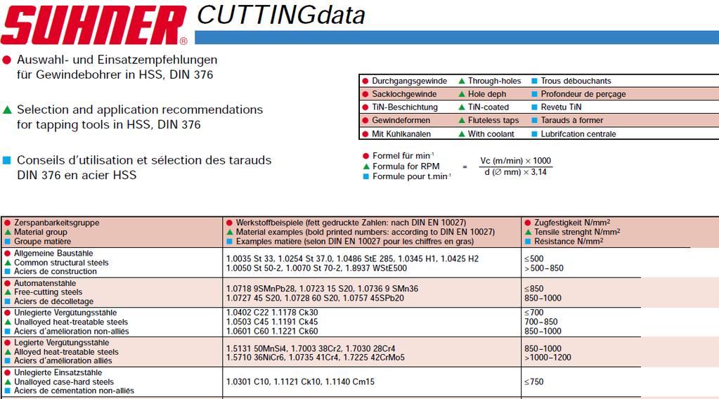
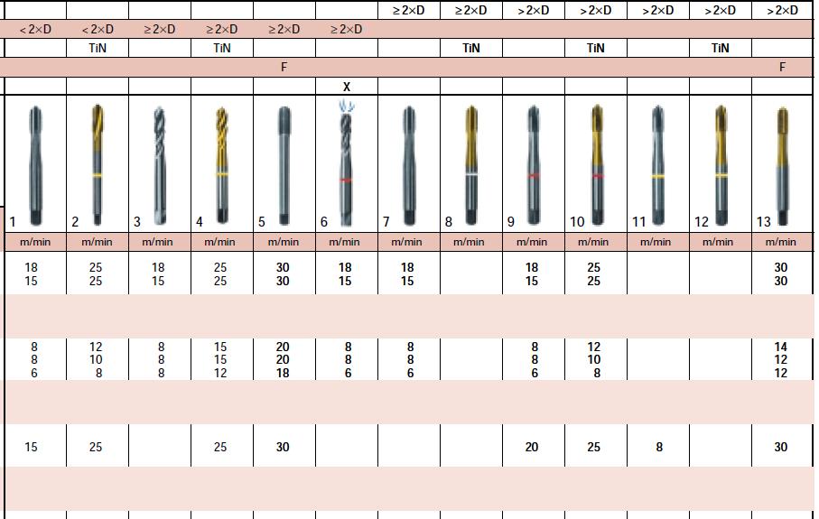
253 Appendices 229
254 Appendices 9.2 Additional rules of drilling one and multiple holes in SPMs Rule 034D If only one hole is required to be machined on the surface, then the material of the workpiece and the size of the hole are determined. Identifying the last two features is important to determine the cutting speed for each material and the suitable machining unit. Rule 035D If the material is cast iron and the hole size is less than or equal to 6 mm, and the cutting speed is 100 m/min, then BEX 35 CNC unit is used with HM-K20 Carbide drill bit. Sliding unit AU 30 is needed with BEX 35 CNC unit. Rule 036D If the material is cast iron and the hole size is less than or equal to 6 mm, and the cutting speed < 100 m/min then BEM 12 MONO unit is used with HSS drill bit. Rule 037D If the material is cast iron and the hole size is > 6 mm and 12 mm, and the cutting speed is >100 m/min, then BEM 28 MONO master is used with HM-K20 Carbide drill bit. Rule 038D If the material is cast iron and the hole size is > 6 mm and 12 mm, and the cutting speed 100 m/min, then BEM MONO is used with HSS drill bit. Rule 039D 230
255 Appendices If the material is cast iron and the hole size is > 12 mm and 20 mm, and the cutting speed is > 100 m/min, then BEX 60 CNC is used with HM-K20 Carbide bit. Slide unit UA 60 is needed with BEX 60 unit. Rule 040D If the material is cast iron and the hole size is > 12 mm and 20 mm, and the cutting speed 100 m/min, then BEM 28 MONO master unit is used with HSS drill bit if. Rule 041D If the material is cast iron and the hole size is > 20 mm and 40 mm, then BEX 60 with slide unit UA 60 are used for any ranges of the cutting speed and for both Carbide and HSS drill bits. Rule 042D If the material is steel and the hole size is less than or equal to 6 mm, and the cutting speed is > 25 m/min, then BEM 12 MONO unit is used with HM-K20 Carbide drill bit. Rule 043D If the material is steel and the hole size is less than or equal to 6 mm, and the cutting speed 25 m/min, then BEM 6 MONO unit is used with HSS drill bit. Rule 044D If the material is steel and the hole size is > 6 mm and 12 mm, and the cutting speed is > 25 m/min, then BEM MONO unit is used with HM- K20 drill bit. Rule 065D If there are two holes on the surface to be machined with low cutting speed in 3 mm diameter size and S is between 9 mm minimum and mm 231
256 Appendices maximum, then BEM 6 MONO unit is used with MH20 multiple spindle heads for any material. Rule 066D If there are two holes on the surface to be machined with high cutting speed in 3 mm diameter size and S is between 9 mm minimum and mm maximum, then BEX 15 CNC unit is used with MH20 multiple spindle heads for any material. Sliding unit UA 15 is needed with BEX 15 unit. Rule 067D If there are two holes on the surface to be machined with low cutting speed in 3 mm diameter size and S is between 7 mm minimum and 190 mm maximum, then BEM 6 MONO unit is used with MHF fixed multiple spindle heads for any material. Rule 068D If there are two holes on the surface to be machined with high cutting speed in 3 mm diameter size and S is between 7 mm minimum and 190 mm maximum, then BEX 15 CNC unit is used with MHF fixed multiple spindle heads for any material. Sliding unit UA 15 is needed with BEX 15 unit. Rules 069D If there are two holes on the surface to be machined with low cutting speed in a diameter > 3 mm and 6 mm and the material is plastics or thermoplastics, and S is between 9 mm minimum and mm maximum, then BEM 6 MONO unit is used with MH20 multiple spindle heads. Rules 070D If there are two holes to be machined on the surface with high cutting speed in a diameter > 3 mm and 6 mm and the material is plastics or thermoplastics, and S is between 9 mm minimum and mm maximum, then BEX 15 CNC 232
257 Appendices unit is used with MH20 multiple spindle heads. Sliding unit UA 15 is needed with BEX 15 unit. Rule 093D If there are three holes to be machined with low cutting speed on the surface in a diameter 3 mm and < 6 mm and straight line pattern with S1 = 9.5 mm and S2 = 97.5 mm, and the material is cast iron, carbon steel, AL-Si alloy, or brass, then BEM 12 MONO unit is used with MH33 multiple spindle head. Rule 094D If there are three holes to be machined with high cutting speed on the surface in a diameter 3 mm and < 6 mm and straight line pattern with S1 = 9.5 mm and S2 = 97.5 mm, and the material is cast iron, carbon steel, AL-Si alloy, or brass, then BEX 15 CNC unit is used with MH33 multiple spindle heads. Sliding unit UA 15 is needed with BEX 15 unit. Rule 095D If there are three holes to be machined with low cutting speed on the surface in a diameter 3 mm and < 6 mm and straight line pattern with S1 = 7 mm and S2 = 190 mm, and the material is cast iron, carbon steel, AL-Si alloy, or brass, then BEM 12 MONO unit is used with MHF multiple spindle heads. Rule 096D If there are three holes to be machined with high cutting speed on the surface in a diameter 3 mm and < 6 mm and straight line pattern with S1 = 7 mm and S2 = 190 mm, and the material is cast iron, carbon steel, AL-Si alloy, or brass, then BEX 15 CNC unit is used with MHF multiple spindle heads. Sliding unit UA 15 is needed with BEX 15 unit. Rule 097D 233
258 Appendices If there are three holes to be machined with low cutting speed on the surface in a diameter 6 mm and < 10 mm and straight line pattern with S1 = 9.5 mm and S2 = 97.5 mm, and the material is cast iron, carbon steel, Al-Si alloy, or brass, then BEM MONO unit is used with MH33 multiple spindle heads. Rule 098D If there are three holes to be machined with high cutting speed on the surface in a diameter 6 mm and < 10 mm and straight line pattern with S1 = 9.5 mm and S2 = 97.5 mm, and the material is cast iron, carbon steel, AL-Si alloy, or brass, then BEX 15 CNC unit is used with MH33 multiple spindle heads. Sliding unit UA 15 is needed with BEX 15 unit. Rule 099D If there are three holes to be machined with low cutting speed on the surface in a diameter 6 mm and < 10 mm and straight line pattern with S1 = 7 mm and S2 = 190 mm, and the material is cast iron, carbon steel, AL-Si alloy, or brass, then BEM MONO unit is used with MHF multiple spindle heads. Rule 100D If there are three holes to be machined with high cutting speed on the surface in a diameter 6 mm and < 10 mm and straight line pattern with S1 = 7 mm and S2 = 190 mm, and the material is cast iron, carbon steel, AL-Si alloy, or brass, then BEX 15 CNC unit is used with MHF multiple spindle heads. Sliding unit UA 15 is needed with BEX 15 unit. Rule 101D If there are three holes to be machined with low cutting speed on the surface in a diameter 10 mm and 16 mm and straight line pattern with S1 = 9.5 mm and S2 = 97.5 mm, and the material is cast iron, carbon steel, AL-Si alloy, or brass, then BEM 28 MONO unit is used with MH33 multiple spindle heads. Rule 117D 234
259 Appendices If there are three holes to be machined with low cutting speed on the surface in a diameter 3 mm and < 6 mm and staggered pattern with S1 = 14.5 mm and S2 = mm, and the material is cast iron, carbon steel, AL-Si alloy, or brass, then BEM 12 MONO unit is used with MH30 multiple spindle head. Rule 118D If there are three holes to be machined with high cutting speed on the surface in a diameter 3 mm and < 6 mm and staggered pattern with S1 = 14.5 mm and S2 = mm, and the material is cast iron, carbon steel, AL-Si alloy, or brass, then BEX 15 CNC unit is used with MH30 multiple spindle heads. Sliding unit UA 15 is needed with BEX 15 unit. Rule 119D If there are three holes to be machined with low cutting speed on the surface in a diameter 3 mm and < 6 mm and staggered pattern with S1 = 7 mm and S2 = 190 mm, and the material is cast iron, carbon steel, AL-Si alloy, or brass, then BEM 12 MONO unit is used with MHF multiple spindle heads. Rule 120D If there are three holes to be machined with high cutting speed on the surface in a diameter 3 mm and < 6 mm and staggered pattern with S1 = 7 mm and S2 = 190 mm, and the material is cast iron, carbon steel, AL-Si alloy, or brass, then BEX 15 CNC unit is used with MHF multiple spindle heads. Sliding unit UA 15 is needed with BEX 15 unit. Rule 121D If there are three holes to be machined with low cutting speed on the surface in a diameter 6 mm and < 10 mm and staggered pattern with S1 = 14.5 mm and S2 = mm, and the material is cast iron, carbon steel, AL-Si alloy, or brass, then BEM MONO unit is used with MH30 multiple spindle heads. Rule 122D 235
260 Appendices If there are three holes to be machined with high cutting speed on the surface in a diameter 6 mm and < 10 mm and staggered pattern with S1 = 14.5 mm and S2 = mm, and the material is cast iron, carbon steel, AL-Si alloy, or brass, then BEX 15 CNC unit is used with MH30 multiple spindle heads. Sliding unit UA 15 is needed with BEX 15 unit. Rule 123D If there are three holes to be machined with low cutting speed on the surface in a diameter 6 mm and < 10 mm and staggered pattern with S1 = 7 mm and S2 = 190 mm, and the material is cast iron, carbon steel, AL-Si alloy, or brass, then BEM MONO unit is used with MHF multiple spindle heads. Rule 124D If there are three holes to be machined with high cutting speed on the surface in a diameter 6 mm and < 10 mm and staggered pattern with S1 = 7 mm and S2 190 mm, and the material is cast iron, carbon steel, AL-Si alloy, or brass, then BEX 15 CNC unit is used with MHF multiple spindle heads. Sliding unit UA 15 is needed with BEX 15 unit. Rule 125D If there are three holes to be machined with low cutting speed on the surface in a diameter 10 mm and 16 mm and staggered pattern with S1 = 14.5 mm and S2 = mm, and the material is cast iron, carbon steel, AL-Si alloy, or brass, then BEM 28 MONO unit is used with MH30 multiple spindle heads. Rule 126D If there are three holes to be machined with high cutting speed on the surface in a diameter 10 mm and 16 mm and staggered pattern with S1 = 14.5 mm and S2 = mm, and the material is cast iron, carbon steel, AL-Si alloy, or brass, then BEX 35 CNC unit is used with MH30 multiple spindle heads. Sliding unit UA 30 is needed with BEX 15 unit. 236
261 Appendices Rule 141D If there are four holes to be machined with low cutting speed on the surface in a diameter 3 mm with S1 = 22 mm and S2 = 195 mm, and the material is cast iron, carbon steel, Al-Si alloy, or brass, then BEM 12 MONO unit is used with MH40 multiple spindle head. Rule 142D If there are four holes to be machined with high cutting speed on the surface in a diameter 3 mm with S1 = 22 mm and S2 = 195 mm, and the material is cast iron, carbon steel, Al-Si alloy, or brass, then BEX 15 CNC unit is used with MH40 multiple spindle heads. Sliding unit UA 15 is needed with BEX 15 unit. Rule 143D If there are four holes to be machined with low cutting speed on the surface in a diameter 3 mm with S1 = 7 mm and S2 = 190 mm, and the material is cast iron, carbon steel, Al-Si alloy, or brass, then BEM 12 MONO unit is used with MHF multiple spindle heads. Rule 144D If there are four holes to be machined with high cutting speed on the surface in a diameter 3 mm with S1 = 7 mm and S2 = 190 mm, and the material is cast iron, carbon steel, Al-Si alloy, or brass, then BEX 15 CNC unit is used with MHF multiple spindle heads. Sliding unit UA 15 is needed with BEX 15 unit. Rule 145D If there are four holes to be machined with low cutting speed on the surface in a diameter > 3 mm and 8 mm with S1 = 22 mm and S2 = 195 mm, and the material is cast iron, carbon steel, Al-Si alloy, or brass, then BEM MONO unit is used with MH40 multiple spindle head. Rule 146D 237
262 Appendices If there are four holes to be machined with high cutting speed on the surface in a diameter > 3 mm and 8 mm with S1 = 22 mm and S2 = 195 mm, and the material is cast iron, carbon steel, Al-Si alloy, or brass, then BEX 15 CNC unit is used with MH40 multiple spindle heads. Sliding unit UA 15 is needed with BEX 15 unit. Rule 147D If there are four holes to be machined with low cutting speed on the surface in a diameter > 3 mm and 8 mm with S1 = 7 mm and S2 = 190 mm, and the material is cast iron, carbon steel, Al-Si alloy, or brass, then BEM MONO unit is used with MHF multiple spindle heads. Rule 148D If there are four holes to be machined with high cutting speed on the surface in a diameter > 3 mm and 8 mm with S1 = 7 mm and S2 = 190 mm, and the material is cast iron, carbon steel, Al-Si alloy, or brass, then BEX 15 CNC unit is used with MHF multiple spindle heads. Sliding unit UA 15 is needed with BEX 15 unit. Rule 149D If there are four holes to be machined with low cutting speed on the surface in a diameter > 8 mm and 16 mm with S1 = 22 mm and S2 = 195 mm, and the material is cast iron, carbon steel, Al-Si alloy, or brass, then BEM 28 MONO unit is used with MH40 multiple spindle head. Rule 150D If there are four holes to be machined with high cutting speed on the surface in a diameter > 8 mm and 16 mm with S1 = 22 mm and S2 = 195 mm, and the material is cast iron, carbon steel, Al-Si alloy, or brass, then BEX 35 CNC unit is used with MH40 multiple spindle heads. Sliding unit UA 30 is needed with BEX 35 unit. 238
263 Appendices 9.3 Additional rules for tapping one and multiple holes in SPMs Rule 034T If only one tap is required to be machined on the surface, then the material of the workpiece and the size of the tap are determined. Identifying the last two features is important to determine the cutting speed and spindle speed for each material which will lead to define the driving power for tapping operation to select the suitable machining unit. Rule 035T If the material is cast iron, steel, brass, or aluminium alloys with M3, M4, M5, and M6 tap sizes, and the cutting speed is 10 m/min, then GEM 6 unit is used with HSS drill bit. Rule 036T If the material is cast iron or steel with M3 tap size, and the cutting speed is > 10 m/min, then GEM 16 unit is used with HSS drill bit. Rule 037T If the material is cast iron or steel with M4 tap size, and the cutting speed is > 10 m/min, then GEM 20C unit is used with HSS drill bit. Rule 038T If the material is cast iron or steel with M5 tap size, and the cutting speed is > 10 m/min, then BEM 20 drilling unit and GSX 50 tapping attachment are used with HSS drill bit. Rule 039T 239
264 Appendices If the material is cast iron or steel with M6 tap size, and the cutting speed is > 10 m/min, then BEM 28 drilling unit and GSX 70 tapping attachment are used with HSS drill bit. Rule 040T If the material is cast iron, steel, brass, or aluminium alloys with M8, M10, M12, and M16 tap sizes, and the cutting speed is 10 m/min, then GEM 16 unit is used with HSS drill bit. Rule 041T If the material is cast iron or steel with M20 tap size, and the cutting speed is 10 m/min, then GEM 20C unit is used with HSS drill bit. Rule 042T If the material is cast iron or steel with M8 tap size, and the cutting speed is > 10 m/min, then BEM 28 and GSX 70 tapping attachment are used with HSS drill bit. Rule 043T If the material is cast iron or steel with M10, M12, M16, and M20 tap size, and the cutting speed is > 10 m/min, then BEX 60 CNC unit and GSX 90 tapping attachment with HSS drill bit. Rule 044T If the material is brass or aluminium alloys with M20 tap size, and the cutting speed is 10 m/min, then GEM 20C unit is used with HSS drill bit. Rule 045T If the material is brass or aluminium alloys with M3, M4, M5, and M6 tap sizes, and the cutting speed is > 10 m/min, then GEM 6 unit is used with HSS drill bit. 240
265 Appendices Rule 046T If the material is brass or aluminium alloys with M8 or M10 tap sizes, and the cutting speed is > 10 m/min, then GEM 16 unit is used with HSS drill bit. Rule 047T If the material is brass or aluminium alloys with M12 or M16 tap sizes, and the cutting speed is > 10 m/min, then GEM 20C unit is used with HSS drill bit. Rule 049T If there are two taps on the surface to be machined with low cutting speed in M3, M4, or M5 sizes with S between 9 mm minimum and mm maximum, and the material is steel, aluminium, brass or plastics, then BEM 6 MONO unit is used with MH20 multiple spindle heads. Rule 050T If there are two taps on the surface to be machined with high cutting speed in M3, M4, or M5 sizes with S between 9 mm minimum and mm maximum, and the material is steel, aluminium, brass or plastics, then BEX 15 CNC unit is used with MH20 multiple spindle heads. Sliding unit UA 15 is needed with BEX 15 unit. Rule 051T If there are two taps on the surface to be machined with low cutting speed in M3, M4, or M5 sizes with S between 7 mm minimum and 190 mm maximum, and the material is steel, aluminium, brass or plastics, then BEM 6 MONO unit is used with MHF multiple spindle heads. Rule 052T If there are two taps on the surface to be machined with high cutting speed in M3, M4, or M5 sizes with S between 7 mm minimum and 190 mm maximum, and the material is steel, aluminium, brass or plastics, then BEX 15 CNC unit is 241
266 Appendices used with MHF multiple spindle heads. Sliding unit UA 15 is needed with BEX 15 unit. Rule 053T If there are two taps on the surface to be machined with low cutting speed in M6 or M8 sizes with S between 9 mm minimum and mm maximum, and the material is steel, aluminium, or brass, then BEM 12 MONO unit is used with MH20 multiple spindle heads. Rule 054T If there are two taps on the surface to be machined with high cutting speed in M6 or M8 sizes with S between 9 mm minimum and mm maximum, and the material is steel, aluminium, or brass, then BEX 15 CNC unit is used with MH20 multiple spindle heads. Sliding unit UA 15 is needed with BEX 15 unit. Rule 055T If there are two taps on the surface to be machined with low cutting speed in M6 or M8 sizes with S between 7 mm minimum and 190 mm maximum, and the material is steel, aluminium, or brass, then BEM 12 MONO unit is used with MHF multiple spindle heads. Rule 056T If there are two taps on the surface to be machined with high cutting speed in M6 or M8 sizes with S between 7 mm minimum and 190 mm maximum, and the material is steel, aluminium, or brass, then BEX 15 CNC unit is used with MHF multiple spindle heads. Sliding unit UA 15 is needed with BEX 15 unit. Rule 057T If there are two taps on the surface to be machined with low cutting speed in M10, M12, or M14 sizes with S between 9 mm minimum and mm 242
267 Appendices maximum, and the material is steel, aluminium, or brass, then BEM 20 MONO unit is used with MH20 multiple spindle heads. Rule 058T If there are two taps on the surface to be machined with high cutting speed in M10 or M12 sizes with S between 9 mm minimum and mm maximum, and the material is steel, aluminium, or brass, then BEX 15 CNC unit is used with MH20 multiple spindle heads. Sliding unit UA 15 is needed with BEX 15 unit. Rule 059T If there are two taps on the surface to be machined with high cutting speed in M14 size with S between 9 mm minimum and mm maximum, and the material is steel, aluminium, or brass, then BEX 35 CNC unit is used with MH20 multiple spindle heads. Sliding unit UA 30 is needed with BEX 35 unit. Rule 085T If there are three taps to be machined with low cutting speed on the surface in M3 or M4 sizes and straight line pattern with S1 = 9.5 mm and S2 = 97.5 mm, and the material is steel, aluminium or brass, then BEM6 MONO unit is used with MH33 multiple spindle head. Rule 086T If there are three taps to be machined with high cutting speed on the surface in M3 or M4 sizes and straight line pattern with S1 = 9.5 mm and S2 = 97.5 mm, and the material is steel, aluminium or brass, then BEX 15 CNC unit is used with MH33 multiple spindle heads. Sliding unit UA 15 is needed with BEX 15 unit. Rule 087T If there are three taps to be machined with low cutting speed on the surface in M3 or M4 sizes and straight line pattern with S1 = 7 mm and S2 = 190 mm, and 243
268 Appendices the material is steel, aluminium or brass, then BEM 6 MONO unit is used with MHF multiple spindle heads. Rule 088T If there are three taps to be machined with high cutting speed on the surface in M3 or M4 sizes and straight line pattern with S1 = 7 mm and S2 = 190 mm, and the material is steel, aluminium or brass, then BEX 15 CNC unit is used with MHF multiple spindle heads. Sliding unit UA 15 is needed with BEX 15 unit. Rule 089T If there are three taps to be machined with low cutting speed on the surface in M5 or M6 sizes and straight line pattern with S1 = 9.5 mm and S2 = 97.5 mm, and the material is steel, aluminium or brass, then BEM 12 MONO unit is used with MH33 multiple spindle head. Rule 090T If there are three taps to be machined with high cutting speed on the surface in M5 or M6 sizes and straight line pattern with S1 = 9.5 mm and S2 = 97.5 mm, and the material is steel, aluminium or brass, then BEX 15 CNC unit is used with MH33 multiple spindle heads. Sliding unit UA 15 is needed with BEX 15 unit. Rule 091T If there are three taps to be machined with low cutting speed on the surface in M5 or M6 sizes and straight line pattern with S1 = 7 mm and S2 = 190 mm, and the material is steel, aluminium or brass, then BEM 12 MONO unit is used with MHF multiple spindle heads. Rule 092T If there are three taps to be machined with high cutting speed on the surface in M5 or M6 sizes and straight line pattern with S1 = 7 mm and S2 = 190 mm, 244
269 Appendices and the material is steel, aluminium or brass, then BEX 15 CNC unit is used with MHF multiple spindle heads. Sliding unit UA 15 is needed with BEX 15 unit. Rule 118T If there are three taps to be machined with low cutting speed on the surface in M3 or M4 sizes and staggered pattern with S1 = 14.5 mm and S2 = mm, and the material is steel, aluminium or brass, then BEM 6 MONO unit is used with MH30 multiple spindle head. Rule 119T If there are three taps to be machined with high cutting speed on the surface in M3 or M4 sizes and staggered pattern with S1 = 14.5 mm and S2 = mm, and the material is steel, aluminium or brass, then BEX 15 CNC unit is used with MH30 multiple spindle heads. Sliding unit UA 15 is needed with BEX 15 unit. Rule 120T If there are three taps to be machined with low cutting speed on the surface in M3 or M4 sizes and staggered pattern with S1 = 7 mm and S2 = 190 mm, and the material is steel, aluminium or brass, then BEM 6 MONO unit is used with MHF multiple spindle heads. Rule 121T If there are three taps to be machined with high cutting speed on the surface in M3 or M4 sizes and staggered pattern with S1 = 7 mm and S2 = 190 mm, and the material is steel, aluminium or brass, then BEX 15 CNC unit is used with MHF multiple spindle heads. Sliding unit UA 15 is needed with BEX 15 unit. Rule 122T If there are three taps to be machined with low cutting speed on the surface in M5 or M6 sizes and staggered pattern with S1 = 14.5 mm and S2 = mm, 245
270 Appendices and the material is steel, aluminium or brass, then BEM 12 MONO unit is used with MH30 multiple spindle head. Rule 123T If there are three taps to be machined with high cutting speed on the surface in M5 or M6 sizes and staggered pattern with S1 = 14.5 mm and S2 = mm, and the material is steel, aluminium or brass, then BEX 15 CNC unit is used with MH30 multiple spindle heads. Sliding unit UA 15 is needed with BEX 15 unit. Rule 124T If there are three taps to be machined with low cutting speed on the surface in M5 or M6 sizes and staggered pattern with S1 = 7 mm and S2 = 190 mm, and the material is steel, aluminium or brass, then BEM 12 MONO unit is used with MHF multiple spindle heads. Rule 125T If there are three taps to be machined with high cutting speed on the surface in M5 or M6 sizes and staggered pattern with S1 = 7 mm and S2 = 190 mm, and the material is steel, aluminium or brass, then BEX 15 CNC unit is used with MHF multiple spindle heads. Sliding unit UA 15 is needed with BEX 15 unit. Rule 126T If there are three taps to be machined with low cutting speed on the surface in M8 or M10 sizes and staggered pattern with S1 = 14.5 mm and S2 = mm, and the material is steel, aluminium or brass, then BEM 20 MONO unit is used with MH30 multiple spindle head. Rule 127T If there are three taps to be machined with high cutting speed on the surface in M8 or M10 sizes and staggered pattern with S1 = 14.5 mm and S2 = mm, and the material is steel, aluminium or brass, then BEX 15 CNC unit is used 246
271 Appendices with MH30 multiple spindle heads. Sliding unit UA 15 is needed with BEX 15 unit. Rule 151T If there are four taps to be machined with low cutting speed on the surface in M3 or M4 sizes with S1 = 22 mm and S2 = 195 mm, and the material is steel, Al- Si alloy or brass, then BEM 6 MONO unit is used with MH40 multiple spindle head. Rule 152T If there are four taps to be machined with low cutting speed on the surface in M3 or M4 sizes with S1 = 7 mm and S2 = 190 mm, and the material is steel, Al- Si alloy or brass, then BEM 6 MONO unit is used with MHF multiple spindle heads. Rule 153T If there are four taps to be machined with low cutting speed on the surface in M5 or M6 sizes with S1 = 22 mm and S2 = 195 mm, and the material is steel, Al- Si alloy or brass, then BEM 12 MONO unit is used with MH40 multiple spindle head. Rule 154T If there are four taps to be machined with low cutting speed on the surface in M5 or M6 sizes with S1 = 7 mm and S2 = 190 mm, and the material is steel, Al- Si alloy or brass, then BEM 12 MONO unit is used with MHF multiple spindle heads. Rule 155T If there are four taps to be machined with low cutting speed on the surface in M8 or M10 sizes with S1 = 22 mm and S2 = 195 mm, and the material is steel, 247
272 Appendices Al-Si alloy or brass, then BEM 20 MONO unit is used with MH40 multiple spindle head. Rule 156T If there are four taps to be machined with low cutting speed on the surface in M8 or M10 sizes with S1 = 7 mm and S2 = 190 mm, and the material is steel, Al- Si alloy or brass, then BEM 20 MONO unit is used with MHF multiple spindle heads. Rule 157T If there are four taps to be machined with low cutting speed on the surface in M12 or M14 sizes with S1 = 22 mm and S2 = 195 mm, and the material is steel, Al-Si alloy or brass, then BEM 28 MONO unit is used with MH40 multiple spindle head. Rule 158T If there are four taps to be machined with low cutting speed on the surface in M12 or M14 sizes with S1 = 7 mm and S2 = 190 mm, and the material is steel, Al-Si alloy or brass, then BEM 28 MONO unit is used with MHF multiple spindle heads. Rule 159T If there are four taps to be machined with high cutting speed on the surface in M3, M4, M5, M6, or M8 sizes with S1 = 22 mm and S2 = 195 mm, and the material is steel, Al-Si alloy or brass, then BEX 15 CNC unit is used with MH40 multiple spindle head. Sliding unit UA 15 is needed with BEX 15 unit. 248
273 Appendices 9.4 Part of the generated code in VisiRule vv do ensure_loaded( system(vrlib) ). relation start1( Conclusion ) if 'q_number of the surfaces'( Conclusion ). relation 'q_number of the surfaces'( Conclusion ) if the answer to 'Number of the surfaces' is _ and check( 'Number of the surfaces', =, one ) and 'q_type of machining operation'( Conclusion ). relation 'q_number of the surfaces'( Conclusion ) if the answer to 'Number of the surfaces' is _ and check( 'Number of the surfaces', =, two ) and continue1( Conclusion ). relation 'q_type of machining operation'( Conclusion ) if the answer to 'Type of machining operation' is _ and check( 'Type of machining operation', =, drilling ) and 'q_the number of the holes '( Conclusion ). relation 'q_type of machining operation'( Conclusion ) if the answer to 'Type of machining operation' is _ and check( 'Type of machining operation', =, tapping ) and 'q_rule 001T'( Conclusion ). relation 'q_the number of the holes '( Conclusion ) if the answer to 'The number of the holes ' is _ and check( 'The number of the holes ', =, one ) and 'q_number of the workstations one hole'( Conclusion ). relation 'q_the number of the holes '( Conclusion ) if the answer to 'The number of the holes ' is _ and check( 'The number of the holes ', =, two ) and 'q_rule 013D'( Conclusion ). relation 'q_the number of the holes '( Conclusion ) if the answer to 'The number of the holes ' is _ and check( 'The number of the holes ', =, three ) and 'q_rule 026D'( Conclusion ). relation 'q_the number of the holes '( Conclusion ) if the answer to 'The number of the holes ' is _ and check( 'The number of the holes ', =, four ) and 'q_rule 48D'( Conclusion ). relation 'q_number of the workstations one hole'( Conclusion ) if 249
274 Appendices the answer to 'Number of the workstations one hole' is _ and q_material( Conclusion ). relation q_material( Conclusion ) if the answer to 'Material' is _ and check( 'Material', =, brass ) and 'q_rule 007'( Conclusion ). relation q_material( Conclusion ) if the answer to 'Material' is _ and check( 'Material', =, 'Cast_iron' ) and 'q_rule 001'( Conclusion ). relation q_material( Conclusion ) if the answer to 'Material' is _ and check( 'Material', =, aluminium ) and 'q_rule 004'( Conclusion ). relation q_material( Conclusion ) if the answer to 'Material' is _ and check( 'Material', =, steel ) and 'q_rule 010'( Conclusion ). relation 'q_rule 007'( Conclusion ) if the answer to 'Rule 007' is _ and check( 'Rule 007', >=, 100 ) and 'q_rule 008'( Conclusion ). relation 'q_rule 007'( Conclusion ) if the answer to 'Rule 007' is _ and check( 'Rule 007', <, 100 ) and 'q_rule 009'( Conclusion ). relation 'q_rule 008'( Conclusion ) if the answer to 'Rule 008' is _ and check( 'Rule 008', =<, 6 ) and Conclusion = 'USE BEX 15 CNC UNIT.~M~JSLIDING UNIT UA 15 IS NEEDED~M~JWITH BEX 15 UNIT.'. relation 'q_rule 008'( Conclusion ) if the answer to 'Rule 008' is _ and [ check( 'Rule 008', >, 6 ) and check( 'Rule 008', =<, 12 ) ] and Conclusion = 'USE BEX 15 CNC UNIT.~M~JSLIDING UNIT UA 15 IS NEEDED~M~JWITH BEX 15 UNIT.'. relation 'q_rule 008'( Conclusion ) if 250
275 Appendices the answer to 'Rule 008' is _ and [ check( 'Rule 008', >, 12 ) and check( 'Rule 008', =<, 20 ) ] and Conclusion = 'USE BEX 35 CNC UNIT.~M~JSLIDING UNIT UA 30 IS NEEDED~M~JWITH BEX 35 UNIT.'. relation 'q_rule 008'( Conclusion ) if the answer to 'Rule 008' is _ and [ check( 'Rule 008', >, 20 ) and check( 'Rule 008', =<, 40 ) ] and Conclusion = 'USE BEX 40 CNC UNIT~M~JAND AU 40 SLIDE UNIT'. relation 'q_rule 009'( Conclusion ) if the answer to 'Rule 009' is _ and check( 'Rule 009', =<, 6 ) and Conclusion = 'USE BEM 6 MONO UNIT'. relation 'q_rule 009'( Conclusion ) if the answer to 'Rule 009' is _ and [ check( 'Rule 009', >, 6 ) and check( 'Rule 009', =<, 12 ) ] and Conclusion = 'USE BEM 12 MONO UNIT'. relation 'q_rule 009'( Conclusion ) if the answer to 'Rule 009' is _ and [ check( 'Rule 009', >, 12 ) and check( 'Rule 009', =<, 20 ) ] and Conclusion = 'USE BEM MONO UNIT'. relation 'q_rule 009'( Conclusion ) if the answer to 'Rule 009' is _ and [ check( 'Rule 009', >, 20 ) and check( 'Rule 009', =<, 40 ) ] and Conclusion = 'USE BEX 40 CNC UNIT~M~JAND AU 40 SLIDE UNIT'. relation 'q_rule 001'( Conclusion ) if the answer to 'Rule 001' is _ and check( 'Rule 001', >, 100 ) and 'q_rule 002'( Conclusion ). 251
276 Appendices relation 'q_rule 001'( Conclusion ) if the answer to 'Rule 001' is _ and check( 'Rule 001', =<, 100 ) and 'q_rule 003'( Conclusion ). relation 'q_rule 002'( Conclusion ) if the answer to 'Rule 002' is _ and check( 'Rule 002', =<, 6 ) and Conclusion = 'USE BEX 35 CNC AND ~M~JAU 30 SLIDE UNIT'. relation 'q_rule 002'( Conclusion ) if the answer to 'Rule 002' is _ and [ check( 'Rule 002', >, 6 ) and check( 'Rule 002', =<, 12 ) ] and Conclusion = 'USE BEM 28 MONO'. relation 'q_rule 002'( Conclusion ) if the answer to 'Rule 002' is _ and [ check( 'Rule 002', >, 12 ) and check( 'Rule 002', =<, 20 ) ] and Conclusion = 'USE BEX 60 CNC AND ~M~JAU 60 SLIDE UNIT'. relation 'q_rule 002'( Conclusion ) if the answer to 'Rule 002' is _ and [ check( 'Rule 002', >, 20 ) and check( 'Rule 002', =<, 40 ) ] and Conclusion = 'USE BEX 60 CNC AND ~M~JAU 60 SLIDE UNIT'. relation 'q_rule 003'( Conclusion ) if the answer to 'Rule 003' is _ and check( 'Rule 003', =<, 6 ) and Conclusion = 'USE BEM 12 MONO'. relation 'q_rule 003'( Conclusion ) if the answer to 'Rule 003' is _ and [ check( 'Rule 003', >, 6 ) and check( 'Rule 003', =<, 12 ) ] and Conclusion = 'USE BEM '. relation 'q_rule 003'( Conclusion ) if 252


277 Appendices 9.5 Additional charts developed in VisiRule 253

278 Appendices 254
279 Appendices 9.6 The design information for a half-collar workpiece 255
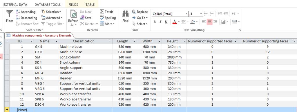
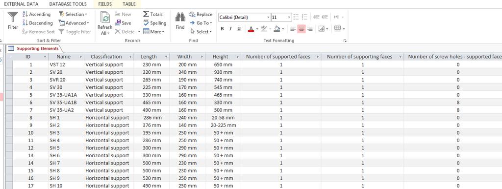
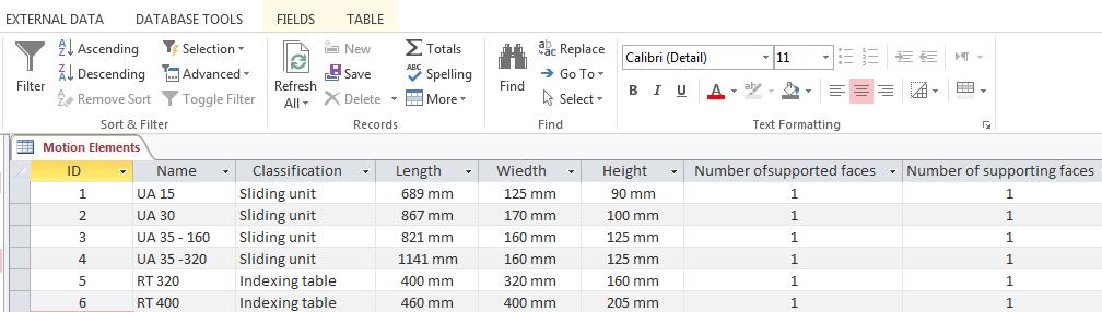
280 Appendices 9.7 Additional figures for the SPM database 256
CMOS digital pixel sensor array with time domain analogue to digital conversion
 Edith Cowan University Research Online Theses: Doctorates and Masters Theses 2004 CMOS digital pixel sensor array with time domain analogue to digital conversion Alistair J. Kitchen Edith Cowan University
TABLE OF CONTENTS CHAPTER TITLE PAGE DECLARATION DEDICATION ACKNOWLEDGEMENT ABSTRACT ABSTRAK
 vii TABLES OF CONTENTS CHAPTER TITLE PAGE DECLARATION DEDICATION ACKNOWLEDGEMENT ABSTRACT ABSTRAK TABLE OF CONTENTS LIST OF TABLES LIST OF FIGURES LIST OF ABREVIATIONS LIST OF SYMBOLS LIST OF APPENDICES
 UNIT-1 INTRODUCATION The field of robotics has its origins in science fiction. The term robot was derived from the English translation of a fantasy play written in Czechoslovakia around 1920. It took another
Processing and Quality Assurance Equipment
 Processing and Quality Assurance Equipment The machine tool, the wash station, and the coordinate measuring machine (CMM) are the principal processing equipment. These machines provide the essential capability
: ADVANCED PRODUCTION PROCESSSES COURSE CODE : 6021 COURSE CATEGORY : A PERIODS/ WEEK : 5 PERIODS/ SEMESTER : 75 CREDIT : 5
 COURSE TITLE : ADVANCED PRODUCTION PROCESSSES COURSE CODE : 6021 COURSE CATEGORY : A PERIODS/ WEEK : 5 PERIODS/ SEMESTER : 75 CREDIT : 5 TIME SCHEDULE MODULE TOPIC PERIODS 1 Turret and Capstan lathes,
Active BIM with Artificial Intelligence for Energy Optimisation in Buildings
 Active BIM with Artificial Intelligence for Energy Optimisation in Buildings by Seyed Saeed Banihashemi Namini B.Arch., MSc A thesis submitted for the degree of Doctor of Philosophy School of Built Environment
Fixtures Design Using Computer for Cylindrical Workpieces in Drilling Operations
 Jazan Univerity College of Engineering Mechanical Engineering Department Fixtures Design Using Computer for Cylindrical Workpieces in Drilling Operations By Team Members: Supervisor (s): Ahmed Mohammd
Application Case. Delta Industrial Automation Products for Vertical CNC Machining Centers with Automatic Tool Changers (ATC)
") Case Delta Industrial Automation Products for Vertical CNC Machining Centers with Automatic Tool Changers (ATC) Issued by Solution Center Date July, 2014 Pages 5 Applicable to Key words NC311 Series CNC
Case Delta Industrial Automation Products for Vertical CNC Machining Centers with Automatic Tool Changers (ATC) Issued by Solution Center Date July, 2014 Pages 5 Applicable to Key words NC311 Series CNC
ENHANCING THE PERFORMANCE OF DISTANCE PROTECTION RELAYS UNDER PRACTICAL OPERATING CONDITIONS
 ENHANCING THE PERFORMANCE OF DISTANCE PROTECTION RELAYS UNDER PRACTICAL OPERATING CONDITIONS by Kerrylynn Rochelle Pillay Submitted in fulfilment of the academic requirements for the Master of Science
Evolving Robot Empathy through the Generation of Artificial Pain in an Adaptive Self-Awareness Framework for Human-Robot Collaborative Tasks
 Evolving Robot Empathy through the Generation of Artificial Pain in an Adaptive Self-Awareness Framework for Human-Robot Collaborative Tasks Muh Anshar Faculty of Engineering and Information Technology
Contents. Notes on the use of this publication
 Contents Preface xxiii Scope Notes on the use of this publication xxv xxvi 1 Layout of drawings 1 1.1 General 1 1.2 Drawing sheets 1 1.3 Title block 2 1.4 Borders and frames 2 1.5 Drawing formats 2 1.6
Trade of Sheet Metalwork. Module 7: Introduction to CNC Sheet Metal Manufacturing Unit 2: CNC Machines Phase 2
 Trade of Sheet Metalwork Module 7: Introduction to CNC Sheet Metal Manufacturing Unit 2: CNC Machines Phase 2 Table of Contents List of Figures... 4 List of Tables... 5 Document Release History... 6 Module
APPLICATION FOR APPROVAL OF A IENG EMPLOYER-MANAGED FURTHER LEARNING PROGRAMME
 APPLICATION FOR APPROVAL OF A IENG EMPLOYER-MANAGED FURTHER LEARNING PROGRAMME When completing this application form, please refer to the relevant JBM guidance notably those setting out the requirements
FLOOR TYPE MILLING-BORING CENTRE
 FR FLOOR TYPE MILLING-BORING CENTRE FR FLOOR TYPE MILLING-BORING CENTRE MULTI-PURPOSE MILLING AND BORING MACHINE HIGH PERFORMANCE, ROBUST MACHINING Greater accuracy and higher efficiency FR FLOOR TYPE
Thesis: Bio-Inspired Vision Model Implementation In Compressed Surveillance Videos by. Saman Poursoltan. Thesis submitted for the degree of
 Thesis: Bio-Inspired Vision Model Implementation In Compressed Surveillance Videos by Saman Poursoltan Thesis submitted for the degree of Doctor of Philosophy in Electrical and Electronic Engineering University
Chapter 22 MACHINING OPERATIONS AND MACHINE TOOLS
 Chapter 22 MACHINING OPERATIONS AND MACHINE TOOLS Turning and Related Operations Drilling and Related Operations Milling Machining Centers and Turning Centers Other Machining Operations High Speed Machining
COURSE TITLE : ADVANCED PRODUCTION PROCESS COURSE CODE : 4028 COURSE CATEGORY : A PERIODS/WEEK : 5 PERIODS/SEMESTER : 90 CREDITS : 4
 COURSE TITLE : ADVANCED PRODUCTION PROCESS COURSE CODE : 4028 COURSE CATEGORY : A PERIODS/WEEK : 5 PERIODS/SEMESTER : 90 CREDITS : 4 TIME SCHEDULE MODULE TOPICS PERIODS 1 Capstan and turret Lathe 21 Automatic
Chapter 14 Automation of Manufacturing Processes and Systems
 Chapter 14 Automation of Manufacturing Processes and Systems Topics in Chapter 14 FIGURE 14.1 Outline of topics described in this chapter. Date 1500Ğ1600 1600Ğ1700 1700Ğ1800 1800Ğ1900 Development Water
Industry and Technology Institutional (ILO), Program (PLO), and Course (SLO) Alignment Number of Courses: 36
, Program (PLO), and Course (SLO) Alignment Number of Courses: 36") Program: Automation, Robotics, and Manufacturing Engineering Technology (ETEC), Manufacturing Technology (MTEC), and Machine Tool Technology (MTT) Institutional SLOs I. Content Knowledge II. Critical,
Program: Automation, Robotics, and Manufacturing Engineering Technology (ETEC), Manufacturing Technology (MTEC), and Machine Tool Technology (MTT) Institutional SLOs I. Content Knowledge II. Critical,
CHAPTER 6. CALCULATION OF TUNING PARAMETERS FOR VIBRATION CONTROL USING LabVIEW
 130 CHAPTER 6 CALCULATION OF TUNING PARAMETERS FOR VIBRATION CONTROL USING LabVIEW 6.1 INTRODUCTION Vibration control of rotating machinery is tougher and a challenging challengerical technical problem.
Robust Hand Gesture Recognition for Robotic Hand Control
 Robust Hand Gesture Recognition for Robotic Hand Control Ankit Chaudhary Robust Hand Gesture Recognition for Robotic Hand Control 123 Ankit Chaudhary Department of Computer Science Northwest Missouri State
VALVE CONDITION MONITORING BY USING ACOUSTIC EMISSION TECHNIQUE MOHD KHAIRUL NAJMIE BIN MOHD NOR BACHELOR OF ENGINEERING UNIVERSITI MALAYSIA PAHANG
 VALVE CONDITION MONITORING BY USING ACOUSTIC EMISSION TECHNIQUE MOHD KHAIRUL NAJMIE BIN MOHD NOR BACHELOR OF ENGINEERING UNIVERSITI MALAYSIA PAHANG VALVE CONDITION MONITORING BY USING ACOUSTIC EMISSION
An Integrated Framework for Assembly-Oriented Product Design and Optimization
 Volume 19, Number 2 - February 2003 to April 2003 An Integrated Framework for Assembly-Oriented Product Design and Optimization By Dr. Qiang Su and Dr. Shana Shiang-Fong Smith KEYWORD SEARCH CAD CIM Design
Geometric Neurodynamical Classifiers Applied to Breast Cancer Detection. Tijana T. Ivancevic
 Geometric Neurodynamical Classifiers Applied to Breast Cancer Detection Tijana T. Ivancevic Thesis submitted for the Degree of Doctor of Philosophy in Applied Mathematics at The University of Adelaide
International Journal of Science and Engineering Research (IJ0SER), Vol 3 Issue 3 March , (P) X
, Vol 3 Issue 3 March , (P) X") Design And Optimization Techniques Using In Turning Fixture M Rajmohan 1, K S Sakthivel 1, S Sanjay 1, A Santhosh 1, P Satheesh 2 1 ( UG Student ) 2 (Assistant professor)mechanical Department, Jay Shriram
Design And Optimization Techniques Using In Turning Fixture M Rajmohan 1, K S Sakthivel 1, S Sanjay 1, A Santhosh 1, P Satheesh 2 1 ( UG Student ) 2 (Assistant professor)mechanical Department, Jay Shriram
Application of Definitive Scripts to Computer Aided Conceptual Design
 University of Warwick Department of Engineering Application of Definitive Scripts to Computer Aided Conceptual Design Alan John Cartwright MSc CEng MIMechE A thesis submitted in compliance with the regulations
Computer-Aided Manufacturing
 Computer-Aided Manufacturing Third Edition Tien-Chien Chang, Richard A. Wysk, and Hsu-Pin (Ben) Wang PEARSON Prentice Hall Upper Saddle River, New Jersey 07458 Contents Chapter 1 Introduction to Manufacturing
Revised Curriculum for Bachelor of Computer Science & Engineering, 2011
 Revised Curriculum for Bachelor of Computer Science & Engineering, 2011 FIRST YEAR FIRST SEMESTER al I Hum/ T / 111A Humanities 4 100 3 II Ph /CSE/T/ 112A Physics - I III Math /CSE/ T/ Mathematics - I
1. SALIENT FEATURES OF THE DIPLOMA PROGRAMME IN MECHANICAL ENGINEERING (TOOL AND DIE)
") 1. SALIENT FEATURES OF THE DIPLOMA PROGRAMME IN MECHANICAL ENGINEERING (TOOL AND DIE) 1) Name of the Programme : Diploma Programme in Mechanical Engineering (Tool and Die) 2) Duration of the Programme
1. SALIENT FEATURES OF THE DIPLOMA PROGRAMME IN MECHANICAL ENGINEERING (TOOL AND DIE) 1) Name of the Programme : Diploma Programme in Mechanical Engineering (Tool and Die) 2) Duration of the Programme
Interactive Tic Tac Toe
 Interactive Tic Tac Toe Stefan Bennie Botha Thesis presented in fulfilment of the requirements for the degree of Honours of Computer Science at the University of the Western Cape Supervisor: Mehrdad Ghaziasgar
TUR 6MN WITH LOADING CRANES. TUR 4MN 3000 x
 TUR 4MN 3000 x 22 000 TUR 6MN WITH LOADING CRANES This lathe, produced for American client, has a unique bed configuration. It consists of two independent beds mounted on a special foundation. This solution
National Conference on Advances in Mechanical Engineering Science (NCAMES-2016)
") Design and Development of Milling Attachment for CNC Turing Center Shashank S 1, Dr.Raghavendra H 2 1 Assistant Professor, Department of Mechanical Engineering, 2 Professor, Department of Mechanical Engineering,
Design and Development of Milling Attachment for CNC Turing Center Shashank S 1, Dr.Raghavendra H 2 1 Assistant Professor, Department of Mechanical Engineering, 2 Professor, Department of Mechanical Engineering,
Methodology for Agent-Oriented Software
 ب.ظ 03:55 1 of 7 2006/10/27 Next: About this document... Methodology for Agent-Oriented Software Design Principal Investigator dr. Frank S. de Boer (frankb@cs.uu.nl) Summary The main research goal of this
Advanced Decision Making for HVAC Engineers
 Advanced Decision Making for HVAC Engineers Javad Khazaii Advanced Decision Making for HVAC Engineers Creating Energy Efficient Smart Buildings Javad Khazaii Engineering Department Kennesaw State University
CHAPTER 6 EXPERIMENTAL VALIDATION AND RESULTS AND DISCUSSIONS
 119 CHAPTER 6 EXPERIMENTAL VALIDATION AND RESULTS AND DISCUSSIONS 6.1 CNC INTRODUCTION The CNC systems were first commercially introduced around 1970, and they applied the soft-wired controller approach
Improving the performance of FBG sensing system
 University of Wollongong Research Online University of Wollongong Thesis Collection 1954-2016 University of Wollongong Thesis Collections 2006 Improving the performance of FBG sensing system Xingyuan Xu
SOLIDWORKS 2018 Basic Tools
 SOLIDWORKS 2018 Basic Tools Getting Started with Parts, Assemblies and Drawings Paul Tran CSWE, CSWI SDC PUBLICATIONS Better Textbooks. Lower Prices. www.sdcpublications.com Powered by TCPDF (www.tcpdf.org)
Planning of the implementation of public policy: a case study of the Board of Studies, N.S.W.
 University of Wollongong Research Online University of Wollongong Thesis Collection 1954-2016 University of Wollongong Thesis Collections 1994 Planning of the implementation of public policy: a case study
DESIGN AND MANUFACTURING OF MODIFIED ANGLE JIG TOOL
 DESIGN AND MANUFACTURING OF MODIFIED ANGLE JIG TOOL ABHIJIT TAGADE 1, NILESH NIRWAN 2, MANISH MISHRA 3 1. M.Tech student, Wainganga college of engineering, Nagpur (India) 2. Facutly, Wainganga college
Seam position detection in pulsed gas metal arc welding
 University of Wollongong Research Online University of Wollongong Thesis Collection 1954-2016 University of Wollongong Thesis Collections 2003 Seam position detection in pulsed gas metal arc welding Hao
Machinist NOA (1998) Subtask to Unit Comparison
 Subtask to Unit Comparison") Machinist NOA (1998) Subtask to Unit Comparison NOA Subtask Task 1 Demonstrates safe working practices. 1.01 Recognizes potential health and safety hazards. A1 Safety in the Machine Shop 1.02 Recognizes
Machinist NOA (1998) Subtask to Unit Comparison NOA Subtask Task 1 Demonstrates safe working practices. 1.01 Recognizes potential health and safety hazards. A1 Safety in the Machine Shop 1.02 Recognizes
On-site Safety Management Using Image Processing and Fuzzy Inference
 1013 On-site Safety Management Using Image Processing and Fuzzy Inference Hongjo Kim 1, Bakri Elhamim 2, Hoyoung Jeong 3, Changyoon Kim 4, and Hyoungkwan Kim 5 1 Graduate Student, School of Civil and Environmental
GCSE Engineering. Schemes of Work
 GCSE Engineering Schemes of Work GUIDANCE FOR SCHEME OF WORK Please find below guidance on and an example of a scheme of work that could be applied for the GCSE Engineering specification. As every centre
Process Planning - The Link Between Varying Products and their Manufacturing Systems p. 37
 Definitions and Strategies Changeability - An Introduction p. 3 Motivation p. 3 Evolution of Factories p. 7 Deriving the Objects of Changeability p. 8 Elements of Changeable Manufacturing p. 10 Factory
Design and Fabrication of Special Purpose Tool Fixture for CNC Turrets
 Design and Fabrication of Special Purpose Tool Fixture for CNC Turrets Prashanth P V 1 and Sachidananda H K 2* 1 Prashanth P V, PG student, Manufacturing Engineering and technology,school of engineering
Laboratory for Manufacturing Systems Department of Mechanical Engineering and Automation University of Patras, Greece
 COMPUTER NUMERICAL CONTROL OF MACHINE TOOLS Laboratory for Manufacturing Systems Department of Mechanical Engineering and Automation University of Patras, Greece Chapter 4: Tool Changing and Tool Registers
A Fuzzy Logic Voltage Collapse Alarm System for Dynamic Loads. Zhang Xi. Master of Science in Electrical and Electronics Engineering
 A Fuzzy Logic Voltage Collapse Alarm System for Dynamic Loads by Zhang Xi Master of Science in Electrical and Electronics Engineering 2012 Faculty of Science and Technology University of Macau A Fuzzy
Machine Tool Technology/Machinist CIP Task Grid
 1 100 ORIENTATION / SAFETY 101 Describe the Occupational Safety and Health Administration (OSHA) and its role in the machining industry. 102 Identify & explain safety equipment and procedures. 103 Identify
DuraTurn Series. CNC Lathe. для получения подробной информации, пожалуйста, напишите нам на почту
 DuraTurn 2030 DuraTurn 2050 DuraTurn 2550 CNC Lathe DuraTurn Series Durable Universal Reliable Affordable Accurate CNC Lathe with Excellent Operability and Machining Capability The DuraTurn series, which
Design Guide: CNC Machining VERSION 3.4
 Design Guide: CNC Machining VERSION 3.4 CNC GUIDE V3.4 Table of Contents Overview...3 Tolerances...4 General Tolerances...4 Part Tolerances...5 Size Limitations...6 Milling...6 Lathe...6 Material Selection...7
Lathe is a machine, which removes the metal from a piece of work to the required shape & size HENRY MAUDSLAY
 TURNING MACHINES LATHE Introduction Lathe is a machine, which removes the metal from a piece of work to the required shape & size HENRY MAUDSLAY - 1797 Types of Lathe Engine Lathe The most common form
Content. Contributors... xix
 Content Contributors... xix 1 Machine Tools for Removal Processes: A General View... 1 L. Norberto López de Lacalle and A. Lamikiz 1.1 Basic Definitions and History... 1 1.1.1 Historical Remarks... 2 1.2
COMPUTER AIDED TRADITION JIGS AND FIXTURES DESIGN
 8 Military Technical College Kobry El-Kobbah, Cairo, Egypt. 17 th International Conference on Applied Mechanics and Mechanical Engineering. COMPUTER AIDED TRADITION JIGS AND FIXTURES DESIGN H.M.A Hussein
Virtual Engineering: Challenges and Solutions for Intuitive Offline Programming for Industrial Robot
 Virtual Engineering: Challenges and Solutions for Intuitive Offline Programming for Industrial Robot Liwei Qi, Xingguo Yin, Haipeng Wang, Li Tao ABB Corporate Research China No. 31 Fu Te Dong San Rd.,
AUTOMATION ACCESSORIES
 RG SERIES AUTOMATION ACCESSORIES The Vision System Faster than contact probes, the ultra-highspeed vision system gives integrated, closed loop control of the machine using the image from the camera. The
Application of NX Siemens PLM software in educational process in preparing students of engineering branch
 Application of NX Siemens PLM software in educational process in preparing students of engineering branch G. M. Sadchikova Citation: AIP Conference Proceedings 1797, 030015 (2017); View online: https://doi.org/10.1063/1.4972454
Efficient Methods for Improving Scalability and Playability of Massively Multiplayer Online Game (MMOG)
") Efficient Methods for Improving Scalability and Playability of Massively Multiplayer Online Game (MMOG) Kusno Prasetya BIT (Sekolah Tinggi Teknik Surabaya, Indonesia), MIT (Hons) (Bond) A dissertation
Efficient Methods for Improving Scalability and Playability of Massively Multiplayer Online Game (MMOG) Kusno Prasetya BIT (Sekolah Tinggi Teknik Surabaya, Indonesia), MIT (Hons) (Bond) A dissertation
in the New Zealand Curriculum
 Technology in the New Zealand Curriculum We ve revised the Technology learning area to strengthen the positioning of digital technologies in the New Zealand Curriculum. The goal of this change is to ensure
The Study of Globoidal Indexing Cam CNC Machine Tools
 Advanced Materials Research Online: 2013-08-30 ISSN: 1662-8985, Vols. 753-755, pp 888-891 doi:10.4028/www.scientific.net/amr.753-755.888 2013 Trans Tech Publications, Switzerland The Study of Globoidal
FUZZY EXPERT SYSTEM FOR DIABETES USING REINFORCED FUZZY ASSESSMENT MECHANISMS M.KALPANA
 FUZZY EXPERT SYSTEM FOR DIABETES USING REINFORCED FUZZY ASSESSMENT MECHANISMS Thesis Submitted to the BHARATHIAR UNIVERSITY in partial fulfillment of the requirements for the award of the Degree of DOCTOR
Projects. 5 For each component, produce a drawing showing the intersection BO.O. C'BORE 18 DIA x 5 DEEP FROM SECTION ON A - A
 Projects ~ Figure Pl Project 1 If you have worked systematically through the assignments in this workbook, you should now be able to tackle the following milling and turning projects. It is suggested that
5500 CNC Lathe Systems (Heavy Duty)
") 5500 CNC Lathe Systems (Heavy Duty) LabVolt Series Datasheet Festo Didactic en 220 V - 50 Hz 04/2018 Table of Contents General Description 2 Features & Benefits 3 List of Available Training Systems 3 Additional
5500 CNC Lathe Systems (Heavy Duty) LabVolt Series Datasheet Festo Didactic en 220 V - 50 Hz 04/2018 Table of Contents General Description 2 Features & Benefits 3 List of Available Training Systems 3 Additional
Design and Development of New Clamping Method for Waterjet Machine (JetCLAMP) based on machining performances
 based on machining performances") International Journal of Engineering & Technology IJET-IJENS Vol:18 No:01 1 Design and Development of New Clamping Method for Waterjet Machine (JetCLAMP) based on machining performances N. Ab Wahab, Muhammad
International Journal of Engineering & Technology IJET-IJENS Vol:18 No:01 1 Design and Development of New Clamping Method for Waterjet Machine (JetCLAMP) based on machining performances N. Ab Wahab, Muhammad
Design & Engineering
 Paras is committed to provide cost-effective solutions that streamline manufacturing cycles, enable collaboration with outside vendors, and ultimately shorten product delivery time. With installations
Clamping devices 521
 Clamping devices 521 522 Product overview Clamping devices Adjustable straps K0001 Hook clamps K0012 Goose-neck straps with long slot K0002 Page 526 Hook Clamps with collar K0013 Page 535 Equipped clamps
Computer-aided Casting Method Design, Simulation and Optimization
 Silver Jubilee Seminar Institute of Indian Foundrymen (Indore Chapter), 13 March 2008, Indore Computer-aided Casting Method Design, Simulation and Optimization Dr. B. Ravi, Professor Mechanical Engineering
Application of Soft Computing Techniques in Water Resources Engineering
 International Journal of Dynamics of Fluids. ISSN 0973-1784 Volume 13, Number 2 (2017), pp. 197-202 Research India Publications http://www.ripublication.com Application of Soft Computing Techniques in
The Design. Building a Sustainable, Moneyless, Socioeconomic System. v EOS
 The Design Building a Sustainable, Moneyless, Socioeconomic System v. 1.0 2011-12-05 EOS board@technate.eu www.eoslife.eu copyright: Public Domain (unless otherwise stated) Table of Contents Introduction...1
AUTOMATIC MODULATION RECOGNITION OF COMMUNICATION SIGNALS
 AUTOMATIC MODULATION RECOGNITION OF COMMUNICATION SIGNALS AUTOMATIC MODULATION RECOGNITION OF COMMUNICATION SIGNALS by Eisayed Eisayed Azzouz Department 01 Electronic & Electrical Engineering, Military
Fixture design of connecting rod parts
 Abstract Fixture design of connecting rod parts Junchen Cao a, Hongen Ge b College of mechanical and Electronic Engineering, Shandong University of Science and Technology, Qingdao 266590, China; a cjch789@126.com,
MSc(CompSc) List of courses offered in
 List of courses offered in") Office of the MSc Programme in Computer Science Department of Computer Science The University of Hong Kong Pokfulam Road, Hong Kong. Tel: (+852) 3917 1828 Fax: (+852) 2547 4442 Email: msccs@cs.hku.hk (The
Office of the MSc Programme in Computer Science Department of Computer Science The University of Hong Kong Pokfulam Road, Hong Kong. Tel: (+852) 3917 1828 Fax: (+852) 2547 4442 Email: msccs@cs.hku.hk (The
Articulating the role of marketing and product innovation capability in export venture performance using ambidexterity and complementarity theory
 Articulating the role of marketing and product innovation capability in export venture performance using ambidexterity and complementarity theory by Wannee Trongpanich School of Management, Faculty of
Full Contents. InRoads Essentials
 Section 1: Overview Essentials 1.1 Introduction... 3 Learning InRoads... 3 Basic Rules... 3 How to Use This Guide... 4 Section Breakdown... 5 Section 1: Overview Essentials... 5 Section 2: Production Essentials...
TIMTOS 2017 EXHIBITS PROFILE
 TIMTOS 2017 EXHIBITS PROFILE Product Code Product Name METAL CUTTING MACHINE TOOL Lathes and Turning Machines 160101 Lathes, Swiss Type 160502 Bench Lathes 160503 High Speed Lathes 160504 Automatic Lathes
SIMULATION OF VIRTUAL MACHINE TOOL DURING THE DEVELOPMENT PHASE SVOČ FST 2016
 SIMULATION OF VIRTUAL MACHINE TOOL DURING THE DEVELOPMENT PHASE SVOČ FST 2016 ABSTRACT Ing. Zdeněk Hájíček, West Bohemia University, Univerzitni 8, 306 14 Pilsen Czech Republic This paper deals with the
AN EFFICIENT APPROACH FOR VISION INSPECTION OF IC CHIPS LIEW KOK WAH
 AN EFFICIENT APPROACH FOR VISION INSPECTION OF IC CHIPS LIEW KOK WAH Report submitted in partial fulfillment of the requirements for the award of the degree of Bachelor of Computer Systems & Software Engineering
Analysis and loss estimation of different multilevel DC-DC converter modules and different proposed multilevel DC-DC converter systems
 The University of Toledo The University of Toledo Digital Repository Theses and Dissertations 2014 Analysis and loss estimation of different multilevel DC-DC converter modules and different proposed multilevel
Study of Vee Plate Manufacturing Method for Indexing Table
 Study of Vee Plate Manufacturing Method for Indexing Table Yeon Taek OH Department of Robot System Engineering, Tongmyong University 428 Sinseon-ro, Nam-gu, Busan, Korea yeonoh@tu.ac.kr Abstract The indexing
MIKRON HPM 1150U HPM 1350U
 MIKRON HPM 1150U HPM 1350U High performance milling versus high speed milling - the one cannot replace the other! While with high speed milling the objective is to create as much surface on the workpiece
University of Southampton Research Repository eprints Soton
 University of Southampton Research Repository eprints Soton Copyright and Moral Rights for this thesis are retained by the author and/or other copyright owners. A copy can be downloaded for personal non-commercial
SOLIDWORKS 2017 Basic Tools
 SOLIDWORKS 2017 Basic Tools Getting Started with Parts, Assemblies and Drawings Paul Tran CSWE, CSWI SDC PUBLICATIONS Better Textbooks. Lower Prices. www.sdcpublications.com Powered by TCPDF (www.tcpdf.org)
PRECISION IN BIG DIMENSIONS VERTICAL TURNING CENTRES VTC
 PRECISION IN BIG DIMENSIONS VERTICAL TURNING CENTRES VTC 2 3 MACHINES WITH GREAT DIMENSIONS AND MACHINING CAPACITY The VTC range has been designed to create new high standards of turning and machining
Design and Analysis of Spindle for Oil Country Lathe
 Design and Analysis of Spindle for Oil Country Lathe Maikel Raj K 1, Dr. Soma V Chetty 2 P.G. Student, Department of Mechanical Engineering, Kuppam Engineering College, Kuppam, Chittoor, India 1 Principal,
Slantbed Lathes N-Series N10 // N20 // N30 // N40 // N50 NILES-SIMMONS
 Slantbed Lathes N-Series N10 // N20 // N30 // N40 // N50 NILES-SIMMONS THE N-SERIES The NILES-SIMMONS N-Series is a modular series of CNC slantbed lathes in fi ve size graduations N10 through N50. The
Autodesk Inventor 2016
 Parametric Modeling with Autodesk Inventor 2016 Randy H. Shih SDC PUBLICATIONS Better Textbooks. Lower Prices. www.sdcpublications.com Powered by TCPDF (www.tcpdf.org) Visit the following websites to learn
Fundamentals of Industrial Control
 Fundamentals of Industrial Control 2nd Edition D. A. Coggan, Editor Practical Guides for Measurement and Control Preface ix Contributors xi Chapter 1 Sensors 1 Applications of Instrumentation 1 Introduction
Turning. MECH Dr Ghassan Al-Kindi - Lecture 10 1
 Turning Single point cutting tool removes material from a rotating workpiece to generate a cylinder Performed on a machine tool called a lathe Variations of turning performed on a lathe: Facing Contour
INTERNATIONAL CONFERENCE ON ENGINEERING DESIGN ICED 05 MELBOURNE, AUGUST 15-18, 2005 AUTOMATIC DESIGN OF A PRESS BRAKE FOR SHEET METAL BENDING
 INTERNATIONAL CONFERENCE ON ENGINEERING DESIGN ICED 05 MELBOURNE, AUGUST 15-18, 2005 AUTOMATIC DESIGN OF A PRESS BRAKE FOR SHEET METAL BENDING Giorgio Colombo, Ambrogio Girotti, Edoardo Rovida Keywords:
Machine Tool Technology/Machinist CIP Task Grid Secondary Competency Task List
 1 100 ORIENTATION / SAFETY 101 Describe the Occupational Safety and Health Administration (OSHA) and its role in the machining industry. 2 2 2 1 0.5 102 Identify & explain safety equipment and procedures.
Formalising Event Reconstruction in Digital Investigations
 Formalising Event Reconstruction in Digital Investigations Pavel Gladyshev The thesis is submitted to University College Dublin for the degree of PhD in the Faculty of Science August 2004 Department of
UNIVERSAL CENTRE LATHES
 UNIVERSAL CENTRE LATHES TRADITION AND EXPERIENCE SR 6000 SR 2000 ŠKODA machine tools of different type and variant have been present in the world market for over 100 years. Among them were a lot of special
Research on Progressive Die Design System Based on Rule-engine
 2017 2nd International Conference on Manufacturing Science and Information Engineering (ICMSIE 2017) ISBN: 978-1-60595-516-2 Research on Progressive Die Design System Based on Rule-engine Shaoling Li and
The jigs and fixtures are the economical ways to produce a component in mass production system. These are special work holding and tool guiding device
 The jigs and fixtures are the economical ways to produce a component in mass production system. These are special work holding and tool guiding device Quality of the performance of a process largely influenced
Turning and Related Operations
 Turning and Related Operations Turning is widely used for machining external cylindrical and conical surfaces. The workpiece rotates and a longitudinally fed single point cutting tool does the cutting.
CNC machining centres. accord 30 fx. CNC machining centre
 CNC machining centres accord 30 fx CNC machining centre accord 30 fx CNC machining centre New-generation modular machining centre designed for machining operations involving heavy duty stock removal with
Component Based Mechatronics Modelling Methodology
 Component Based Mechatronics Modelling Methodology R.Sell, M.Tamre Department of Mechatronics, Tallinn Technical University, Tallinn, Estonia ABSTRACT There is long history of developing modelling systems
SOLIDWORKS 2015 and Engineering Graphics
 SOLIDWORKS 2015 and Engineering Graphics An Integrated Approach Randy H. Shih SDC PUBLICATIONS Better Textbooks. Lower Prices. www.sdcpublications.com Powered by TCPDF (www.tcpdf.org) Visit the following
Structural Analysis Control System Engineering Cim Elective I Computer Graphics for Cad/Cam. Advanced in Operating System Design
 Sr No Name of Branch RASHTRASANT TUKADOJI MAHARAJ NAGPUR UNIVERSITY **** MTECH,ME,MDES, MARCH FIRST SEMESTER EXAMINATION OF summer 2015 # PROGRAMME( WRITTEN ) # MTech,ME,MDes,MArch FIREST SEMESTERsummer
Experimental investigation of crack in aluminum cantilever beam using vibration monitoring technique
 International Journal of Computational Engineering Research Vol, 04 Issue, 4 Experimental investigation of crack in aluminum cantilever beam using vibration monitoring technique 1, Akhilesh Kumar, & 2,
Tools for Design. with VEX Robot Kit: Randy H. Shih Oregon Institute of Technology SDC PUBLICATIONS
 Tools for Design with VEX Robot Kit: AutoCAD 2011 and Autodesk Inventor 2011 2D Drawing 3D Modeling Hand Sketching Randy H. Shih Oregon Institute of Technology INSIDE: SUPPLEMENTAL FILES ON CD SDC PUBLICATIONS