Fixtures Design Using Computer for Cylindrical Workpieces in Drilling Operations
|
|
|
- Madlyn Kathlyn Short
- 5 years ago
- Views:
Transcription

1 Jazan Univerity College of Engineering Mechanical Engineering Department Fixtures Design Using Computer for Cylindrical Workpieces in Drilling Operations By Team Members: Supervisor (s): Ahmed Mohammd Ali Hammadi Hassan Jobran Al-Malki Jaber Hadi Alassiri Majed Ali Almalki Saud Hassan Qurby Dr. Mahmoud Mohamed Atta Mahmoud A Senior Project Final Report submitted in partial fulfillment of the requirement for the degree of BACHELOR OF Science (B.Sc.), in Mechanical Engineering (Rajab 1435) (May 2014)
2 College of Engineering Jazan University Fixtures Design Using Computer for Cylindrical Workpieces in Drilling Operations APPROVAL RECOMMENDED: Examination Committee Dr. Helmy M. O. Abulila Dr. Gaber El-Awadi Dr. Mahmoud Mohamed Atta PROJECT SUPERVISOR (s): Dr. Mahmoud Mohamed Atta DEPARTMENT HEAD: Dr. Ali Al Shahrany. COURSE INSTRUCTOR: APPROVED: Dr. Mohamed Nour Al Maghrabi
3 ABSTRACT The product quality, manufacturing time, cost and interchangeability of products are occupied the manufacturing systems planners. Work holding devices are the tooling elements that have a large effect in all of these problems. Fixture is a special holding device use to help in controlling these problems. The lack of fixture flexibility decrease the flexibility of the whole manufacturing system to face rapid change in products design and high competitive between products. Modular fixture is the preferred flexible fixture systems to solve these problems in job or small batch lot size systems. Fixture design is a highly complicated procedure and time consuming. Computer systems and software can be used in creation, or analysis of the modular fixture design. The use of computer will help in the reducing the lead time, obtaining most alternatives in a shorter time, saving and using experiences of others. Through the present project an excel sheet is prepared for designing fixtures (selection the suitable modular fixture elements) for drilling holes in cylindrical workpieces parallel to the its axis. At the end, an assembly sheet (contains the used modular fixture elements, its position and orientation and the location of the workpiece with respect to these elements) is prepared. AutoCAD is used to produce a data base of the 3D model of the modular fixture elements and make the final assembly of the designed fixture. The resulting errors in the workpiece, due to the accuracy of the modular fixture elements, are obtained. iii
4 DEDICATION To our Parents, who, through their financial and moral support were the source of inspiration and the mainstay in our attaining an education, we dedicate this project. iv
5 ACKNOWLEDGEMENT This project was written under the direction and supervision of Dr. Mahmoud Mohamed Atta Mahmoud we would like to express our sincere appreciation to him for the interest and assistance given to us. v
6 TABLE OF CONTENTS PAGE ABSTRACT.. EDICATION. iii iv ACKNOWLEDGEMENT... v TABLE OF CONTENTS.... LIST OF FIGURES NOMENCLATURE vi viii xi CHAPTER 1. INTRODUCTION The rule of fixture The flexible fixture Problem statement Problem justification and outcomes 5 2. JIGS AND FIXTURES Purpose and advantages of jigs and fixture Fixture design principles Basic requirements of fixtures Locating principles Clamping principles Modular fixture system FIXTUER DESIGN FOR CYLINDRICAL WORKPIECE IN DRILLING HOLES PARALLEL TO ITS AXIS Workpiece configurations, locating and clamping surfaces Fixture design algorithm Locating points and elements Clamping point and elements 26 vi
7 3-2-3 Assembly sheet Fixture errors RESULTS AND DISCUSSION Fixture design for blind holes with top clamp Fixture design for through holes with top clamp Fixture design for counter boring holes with top clamp Fixture design for countersinking holes with top clamp Fixture design for blind holes with side clamp Fixture design for counter boring holes with side clamp FEASIBIILITY STUDIES AND MARKET NEEDS CONCLUSIONS, RECIMMENDATIONS AND FUTURE WORK Conclusions Recommendations and future work APPENDIXES 52 A: Project team with assigned responsibilities, 52 B: Faculty advisers and industry sponsors 52 C: Project budget and expenses to date 52 D: Drawing package (if applicable) 52 E: Manufacturing procedures, test procedures and test reports 52 F: Technical reports or evaluations 52 G: Toolroom Starter Sets of CarrLane manufacturing company 53 REFERENCES 58 vii
8 LIST OF FIGURES FIGURE No DESCRIPTION PAGE (Fig. 1.1) The rule of fixture design in manufacturing system. 2 (Fig. 1.2) The current flexible fixture methodologies. 4 (Fig. 2.1) Configuration and construction of a jig. 7 (Fig. 2-2) Configuration and construction of a fixture. 7 (Fig. 2-3) The six degrees of freedom of the rigid body. 10 (Fig. 2-4) The locating principle to restrict the workpiece that a three mutually perpendicular surfaces 11 (Fig. 2-5) The locating system for cylindrical parts. 12 (Fig. 2-6) The locating system for internal holes parts. 12 (Fig. 2-7) Side clamp. 13 (Fig. 2-8) Top clamp. 14 (Fig. 2-9) Types of modular fixture systems. 15 (Fig. 2-10) The hole base system functional sets elements. 16 (Fig. 3-1) The flowchart for the design procedures for fixture. 18 (Fig. 3-2) An example of workpiece configuration 19 (Fig. 3-3) An example of workpiece configuration in the machining orientation. 20 (Fig. 3-4) The flowchart for the design algorithm. 22,23 (Fig. 3-5) The inputs in the excel sheet. 24 (Fig.3-6) The used locating elements. 24 (Fig. 3-7) The excel equation for selection the primary and secondary location. 24 (Fig. 3-8) The workpiece with the locators. 25 (Fig. 3-9) The used clamping elements. 26 viii
9 (Fig. 3-10) (Fig. 3-11) The effect of the support accuracy and the distance between the supports on the tilting angles of the workpiece. 27 The position error due to accuracy of the side locators. 28 (Fig. 4-1) The required product for blind holes. 30 (Fig. 4-2) (Fig. 4-3) (Fig. 4-4) (Fig. 4-5) The required workpiece with its orientation and in its place, blind holes. 30 A part of excel sheet for blind holes making, top clamp. 31 The assembly sheet for the blind holes fixtures, top clamp. 31 The assembly of the blind holes fixture with the workpiece in place, top clamp. 32. (Fig. 4-6) The required product for through holes. 33 (Fig. 4-7) (Fig. 4-8) (Fig. 4-9) (Fig. 4-10) The required workpiece with its orientation and in its place, through holes. 33 A part of Excel sheet for through holes making, top clamp. 34 The assembly sheet for the through holes fixtures, top clamp. 34 The assembly of the through holes fixture with the workpiece in place, top clamp. 35 (Fig4-11) The required product for counter boring holes. 36 (Fig 4-12) (Fig 4-13) (Fig. 4-14) (Fig. 4-15) The required workpiece with its orientation and in its place, counter boring holes. 36 A part of Excel sheet for counter boring holes making, top clamp. 37 The assembly sheet for the counter boring holes fixtures, top clamp. 37 The assembly of the counter boring holes fixture with the workpiece in place, top clamp. 38 (Fig. 4-16) The required product for countersinking holes. 39 ix
10 (Fig. 4-17) (Fig. 4-18) (Fig 4-19) (Fig 4-20) (Fig. 4-21) (Fig. 4-22) (Fig. 4-23) (Fig. 4-24) (Fig4-25) (Fig 4-26) The required workpiece with its orientation and in its place, countersinking holes. 39 A part of Excel sheet for countersinking holes making, top clamp. 40 The assembly sheet for the countersinking holes fixtures, top clamp. 40 The assembly of the countersinking holes fixture with the workpiece in place, top clamp. 41 A part of Excel sheet for blind holes making, with side clamp. 42 The assembly sheet for the blind holes fixtures, with side clamp. 42 The assembly of the blind holes fixture with the workpiece in place, side clamp. 43 A part of Excel sheet for counter boring holes making, side clamp. 44 The assembly sheet for the counter boring holes fixtures, side clamp. 45 The assembly of the counter boring holes fixture with the workpiece in place, side clamp. 45 (Fig 4-27) The views of the fixture of the assembly fig (Fig. 4-28) The views of the fixture of the assembly fig (Fig. 5-1) The economical comparison between different methodologies of fixture. 49 x
11 NOMENCLATURE Symbols Description UNITS d Diameter of the primary locating surface mm h1 Min. height required for primary locating surface mm h2 Min. height of clamping surface mm α Tilting angle of workpiece in the X direction Deg. β Tilting angle of workpiece in the Y direction Deg x Position error of the workpiece mm c Tolerance of the modular fixture elements mm θ θ new Central angle between the primary and secondary locators. Deg The expected central angle due to the side locators tolerances Deg xi
12 CHAPTER 1 INTRODUCTION
13 CHAPTER 1 INTRODUCTION The most common problem facing any company is to produce its products with the highest quality, in the shortest time and with the minimum cost. The ways to achieve these goals are, in some manner, conflicted (the high quality with the shortest time and minimum cost), while other ways are coincide (the shortest time with the minimum cost). The use of suitable holding device can achieve all these goals together to a certain high degree. Nowadays, Another problem facing the manufacturing companies are the interchangeability of the products. This interchangeability are affected by the manufacturing procedures, and holding devices used in producing these parts. 1-1 THE RULE OF FIXTURE Workpiece holding devices are critical components in the manufacturing system because of its effect in the part accuracy, product cost and lead time (its effect in loading and unloading time and total machining time). These holding devices can be classified into two branches; a) General purpose holding devices; such as chuck (3 jaws or 4 jaws), vise, face plate,.. etc. It can be used to hold workpieces but with larger time to achieve higher accuracy which may increase the cost. b) Special holding devices; jig and fixture. It can be produced to hold a certain workpiece lot size or a group of workpieces lot sizes. That holding devices increase the initial cost but decrease the loading and unloading time, the current cost, and increase the quality. 1
14 Fixtures are special workholding devices that designed to hold, locate and support workpieces against the tool (cutting tool, assembly tools, or inspection tools) during manufacturing operations (machining, assembly or inspection). The rule of the fixture in the manufacturing systems is shown in fig.1.1 [1]. The fixture design begin with the product geometry and process planning of the product and ended with the fixture assembly in the production system. Fig. 1.1 The rule of fixture design in manufacturing system. With the use of modern machine tools the machining time is reduced to a high degree because of the reduce of human effect and the use of heavier feed and depth of cut. This gives the time for loading and unloading of the machining parts and the rigidity, to withstand the high feeding forces, a large amount of considerations in the manufacturing system. Fixture is used to improve the performance of the manufacturing system in these fields, reduce the loading and unloading time and increase the rigidity of the holding devices. The design of the fixture will be discussed in chapter 2. 2
15 Fixturing methodologies are usually determined by the size of the lots. In the mass production manufacturing system, the number of parts can face the fixture costs and the leading time in design and manufacturing the indicated fixture. But; in the job or in batch manufacturing systems the product cost and the lead time to the production cycle are increased significantly with the design and manufacturing the fixture to a certain product manufacturing cycle. 1-2 THE FLEXIBLE FIXTURE The rapid change of in the products design, the shorting of the lead time and competitive between the different products and the achieving high accuracy are problems facing the manufacturing system. These problems required a degree of flexibility in the manufacturing system to be solved. The flexibilities of the manufacturing systems are faced with the lake of flexibility in the design and manufacturing of the indicated fixtures. Without using flexible fixture the overall FMS could not be realized real flexibility. Fig. 1.2 summarize the current flexible fixture methodologies, their flexibility source and sub categories. Modular fixture, which use the assembly of standard components to achieve the fixture, can be used as a flexible fixture system to face the small lot size because these components are disassembled and reassembled to produce much more fixture configurations [1]. The computer is used to increase the speed of selection and drawing assembly of the mechanical components. This can be used in the field of fixture design to reduce the lead time used in the design and manufacturing of the required fixtures. 3
16 Fig. 1.2 The current flexible fixture methodologies. 1-3 PROBLEM STATEMENT The previous introduction shows that the problem may be a treated as how to use the computer to design a flexible system for manufacturing fixture used to hold a small lot size of products with a small lead time. Modular fixture are preferred because of its generality and it consists of a standard elements that are used to accomplish a certain fixture then disassemblies and reassembled in other fixture and so on. This increase the flexibility of the system and reduce the tooling cost for job and small size lots in batch lot manufacturing systems. The use of computer is to minimize the lead time in design of the fixture. The lead time in selection the modular fixture components required for a certain fixture and preparing the assembly sheet of this fixture. Also; reduce the time which is consumed in preparing the drawing sheets for this fixture. 4
17 1-4 PROBLEM JUSTIFICATION AND OUTCOMES As a result this project uses modular fixture as a flexible fixture methodology to overcome the problem of small lot size and fixture cost. The kits of the modular fixture are collected from the catalog of modular fixture produced by Carr Lane Company, USA. These 3D geometrical models of these kits, modular fixture elements, are prepared with AutoCAD software (Note the 2d of these kits are available in the website of the company). By using the Excel 2007 the selection of the modular fixture elements are made, and their position in the base plate and their orientation are calculated. At the end assembly sheet of the selected elements, position and orientation are made. At the end the 3D geometrical model of this assembly sheet of modular element, which are prepared through the project, with the workpiece can be viewed with AutoCAD (version 2004 at later versions).. 5
18 CHAPTER 2 JIGS AND FIXTURES
19 CHAPTER 2 JIGS AND FIXTURES Jigs and fixtures are devices used to facilitate production work, making interchangeable pieces of work possible at a savings in cost of production. They are used to locate and hold the work that is to be machined. These devices are provided with attachments for guiding, setting, and supporting the tools in such a manner that all the workpieces produced with them, jig or fixture, will be exactly alike in every way. So, The employment of unskilled labor is possible when they can be used in production work. And the repetitive layout and setup (which are timeconsuming activities and require consider-able skill) are eliminated. Also, the use of these devices can result in such a degree of accuracy that workpieces can be assembled with a minimum amount of fitting [3]. Jig is a work holding device that holds, supports and locates the workpiece and guides the cutting tool for a specific operation. Figure 2-1 shows a configuration and construction of a certain jig. The word jig is used in the drilling or boring operations and it should have a guiding for the tool. The jigs consist of clamping element(s), locators, drilling plate and drilling bush(s) for guiding the drill during the drilling operations. The elements are assemblies together with different assembling operations (welding joints, bolted joints,.. etc). jigs are identified with their basic construction; open jig (such as; plate jig, sandwich jigs,.. etc), closed jigs (such as; channel jigs and leaf jigs, etc) [4]. Fixtures have wider scope of application than jigs. Fixture is primarily a holding device. A fixture, fig 2-2, holds the workpiece firmly in place for the machining operation, but it does not form a guide for the tool. They are designed for processes where the tools cannot be guided 6

![Fixtures are identified with the machine tool where they are used; milling fixture, turning fixture.. etc. [2].](/docs-images/90/102247516/images/20-1.jpg "Drilling bush Drilling plate Clamping locators Base and foots Fig 2-1 Configuration and construction of a jig [5]. Fig 2-2 Configuration and construction of a fixture.")
20 easily. Within; the fixture there is an element position the way tool, cutter as an example, with respect to the workpiece called tool setting and it should be bolted to the machine table. Fixtures are identified with the machine tool where they are used; milling fixture, turning fixture.. etc. [2]. Drilling bush Drilling plate Clamping locators Base and foots Fig 2-1 Configuration and construction of a jig [5]. Fig 2-2 Configuration and construction of a fixture. It is sometimes difficult to differentiate between a jig and a fixture, since their basic functions can overlap in the more complicated designs. The best means of differentiating between the two devices is to apply the basic definitions, as follows: 7
21 1. The jig is a guide device while the fixture is a holding device. 2. The jig has foot to be placed on the machine table while the fixture may be secured and located to the machine table with a bolts and tenons respectively. 3. The jigs contain a drilling plate and bushes to guide the tool while the fixture may contain setting block to position the tool. 2-1 PURPOSE AND ADVANTAGES OF JIGS AND FIXTURES For the above section the following purpose and advantages of jigs and fixtures can be noted [6]: a) It reduces marking, measuring and setting of workpiece times and maintains the accuracy of performance. b) Reducing loading time for workpiece and tool adjusting time. c) Help in achieving consistent quality and high interchangeability. d) Reduces production cycle time so increases production. e) More than one tool can be used at the same time. f) Operating conditions (speed, feed rate and depth of cut) can be increased due to rigidity of clamping of workpiece by jigs and fixtures. g) Comfort the operators since the setting of workpiece can be eliminated. h) low skilled operators can be employed which can saves the cost of manpower. 2-2 FIXTURE DESIGN PRINCIPLES From the definition of the fixture should contain three main groups of elements; location elements, clamping elements and supporting elements. The role and examples of these elements will be discussed later 8
22 through this chapter. First; the requirements of the fixtures are discussed. At the end of the chapter the used flexible fixture system, modular fixture will be discussed Basic Requirements of Fixtures 1. Ensuring positional accuracy of workpiece, to achieve the higher product accuracy. 2. Ensuring operation convenience and safety, the operator can achieve the required work with min. effort, at min. time and with a high degree of accuracy. 3. Ensuring productivity in the production system, higher production rate than the conventional work without fixture. 4. Ensuring low production cost, according to the number of products required Locating Principles The most important task of fixture design is to locate the workpiece with an acceptable accuracy. The role of locating system is to ensure a relative position between the workpiece and machining tools. The locating process places a set of workpiece faces, called locating datum surfaces, in contact with fixture locators. If the workpiece surfaces are separated from contact with the locators, the location is failed. Once the positions and orientations of locating surfaces are determined other features or surfaces of the workpiece are determined with respect to the machine table and the machining tools. For any rigid body (workpiece), there are six degrees of freedom describing the position and orientation of this body. Figure 2-3 shows this 6 degrees of freedom, three linear movements in X, Y and Z directions 9

23 and three rotational movements about X, Y and Z Axes. The aim of the fixture designer in this stage is to restrict all or part of these 6 degrees of freedom, so that the position or orientation of the workpiece can be uniquely determined. Fig 2-3 The six degrees of freedom of the rigid body. Based on kinematics principles, six independent point are required to achieve these restriction. Figure 2-4 shows how to restrict the workpiece that has a three mutually perpendicular surfaces. This principle is called locating principle. This means that the 1 st surface, called primary locating surface, is restricted against 3 points, the 2 nd surface, called the secondary locating surface, is restricted with 2 points, while the 3 rd surface, called the third locating surface, is restricted with only one point. The first 3 points restrict the motion along Z direction, rotation about X and Y axes. The second 2 points restrict the motion along Y direction, rotation about Z axis. While the last point restrict the motion along X direction. 01
 shows the application of the 3-2-1 locating principle for the cylindrical")
24 The role of locating system is to ensure a relative position between the workpiece and machining tools. Fig 2-4 The locating principle to restrict the workpiece that a three mutually perpendicular surfaces Figure 2-5 (a) shows the application of the locating principle for the cylindrical workpiece. Figure 2-5 (b) shows the use of v-block in the location of the cylindrical parts, the v-block restricted 5 degrees of freedom (motions along X and Z directions, rotation about X and Z axis), the stopper restricted the motion along y direction, while the 6 th degrees of freedom is not taken into considerations because of the symmetry about Y axis. If the workpiece has internal holes, these holes can be used as primary and secondary locating surfaces, fig2-6. The primary locating surface is one internal hole, has cylindrical shape which restricted 5 degrees of freedom, the secondary locator is the farthest hole from the primary locating hole and its shape is diamond restricted the 6 th degree of freedom. Figure 2-6 (a) shows the workpiece with the locators, while Figure 2-6 (b) shows the shape of the locators. 00
 Using the V block to achieve this principle for cylindrical parts.")
 Workpiece with locators b) Locators shape Fig 2-6 The locating system for internal holes parts.")

 The clamping should keep the workpiece in contact with locators, so")
25 v-block Stopper a) The locating principle for cylindrical parts. b) Using the V block to achieve this principle for cylindrical parts. Fig 2-5 The locating system for cylindrical parts. a) Workpiece with locators b) Locators shape Fig 2-6 The locating system for internal holes parts Clamping principles The clamping system purpose is to securely hold the position of workpiece against locators though the machining process. The basic requirements of the clamping system to keep the workpiece in the locating position with minimum deformation are; 1) The clamping should keep the workpiece in contact with locators, so the location is ensured. 2) The clamping force is enough to resist the machining forces and not great to cause a deformation in the workpiece. 01
 The clamping device should be suitable for the production type and batch size.")
26 3) The clamping operation should be simple, time saving safe and easy. Also, no impact load on the workpiece, machine tool and cutting tools. 4) The clamping device should be suitable for the production type and batch size. In order to reduce the deformation the clamping direction should be directed toward the major locating surface with a large contact areas. Properly selecting of the clamping direction can lead to smaller clamping force required. When it is coincide with the gravity or the cutting force it may be smaller. The clamping position can be determined such that it is not damage the location and the workpiece deformation is minimum. For example the clamping forces should be inside the locating points not outside it. Figure 2-7 shows a side clamp where the clamping position is taken at a height lower than the height of the opposite locator. Figure 2-8 shows a top clamp where the clamping position is taken above a supporting element Fig. 2-7 Side clamp 2-3 MODULAR FIXTURE SYSTEM Flexible fixturing has become an important component of flexible manufacturing systems (FMS) and computer-integrated manufacturing systems (CIMS). There are several different categories of flexible fixtures 01
![(shown in the previous chapter), but modular fixtures are most widely used in industry for job and batch production [7].](/docs-images/90/102247516/images/27-0.jpg "Modular fixturing can be defined as a system for building several combinations of standard components that can serve a wide variety of workpieces.")
27 (shown in the previous chapter), but modular fixtures are most widely used in industry for job and batch production [7]. Modular fixturing can be defined as a system for building several combinations of standard components that can serve a wide variety of workpieces. These fixture elements can be assembled and reused in order to generate different constructions of jigs and fixtures [8]. The flexibility of the modular fixtures is derived from the large number of fixture configurations from different combinations of the fixture element. Fig. 2-8 Top clamp Commercially available modular fixturing systems can be classified into two types: T-slot and hole-based systems. Slot-based modular fixtures have parallel and perpendicular T-slots on the base plates (Fig. 2-8 a). The use of modular fixtures enhances fixture flexibility and reduces the time and cost of fixture development, which is especially beneficial to small-volume production and new product prototyping. Hole-based modular fixtures have accurately positioned holes on the base plates (Fig. 2-8 b). The CarrLane manufacturing company, USA, hole based modular fixture system, appendix (g) shows the toolroom sets of it, will be used through this project. The hole base system consists functional set of elements, fig These sets are base plates set, supports set, locators set, clamps set and fasten components set. 01


28 a) T- slot based modular b) Hole based modular fixture fixture system system Fig. 2-9 Types of modular fixture systems Fixture design, fabrication, and testing consume a major portion of production development time. In a manufacturing system, it is desirable that fixtures be flexible so that the leading time of the products can be reduced. The use of computer in the selection and in drawing the fixture elements assembly will reduce this lead time and provide the system with the past experience from the designers. Excel program can be programmed to select the most suitable fixture elements and make the assembly sheet for these elements. Also, AutoCAD [9] can be used to assemblies these elements and make the required drawing views with the pre-prepared 3D models of the fixture elements. At the end the predicted values error can be calculated according to the tolerance of the used elements. 01

29 Fig.2-10 The hole base system functional sets elements. 06
30 CHAPTER 3 FIXTUER DESIGN FOR CYLINDRICAL WORKPIECE IN DRILLING HOLES PARALLEL TO ITS AXIS
31 CHAPTER 3 FIXTUER DESIGN FOR CYLINDRICAL WORKPIECE IN DRILLING HOLES PARALLEL TO ITS AXIS The fixture design tasks begin with the gathering data about the workpiece (dimensions and geometry), and process plan of the product (the jobs done in each set up and the machine used to perform that job). According to the previous information the locating and clamping surface are obtained, then the locating and clamping point are selected. Then, the different functional elements are selected and the configuration of the fixture can be finished. The verification of the fixture be prepared (determine the resulting errors and the clamping forces and chuck if it was with the accuracy limits of the workpiece). At the end the assembly sheet and drawing can be done. Figure 3-1 shows the flowchart of these procedures. 3-1 WORKPIECE CONFIGURATIONS, LOCATING AND CLAMPING SURFACES Though this project, fixture for cylindrical workpiece that required to drilled with holes parallel to its axis will be designed. Figure 3-2 shows an example for this workpiece. This type of workpieces are symmetry about its axis, which means that it is required to restricted five degrees of freedom only to locate the workpiece completely. These restrictions are distributed into two surfaces; primary locating surface has three restrictions and secondary locating surface 71

32 which has two restriction. The 3 locating restrictions on the primary location surface restrict the motion in the z direction (direction of the drill), and rotation about X and Y axes. The two other locating on the secondary locating system restrict the motion in the direction of X and Y directions. The rotation about the Z axis, the direction parallel to the drill axis, is not necessary to restricted because of symmetry about it. Fig. 3-1 The flowchart for the design procedures for fixture. The first step in the fixture design is the defined the locating and clamping surface of the workpiece. This step is made through four stages, which are; 1- Oriented the workpiece machined surface to the direction of the tool. The axis of the drill in the drilling machine tool is vertical. So, the workpiece should be oriented in a vertical position permit the drill to produce the hole. 71
 that contains the holes required to machined.")
33 S1 S3 S2 Drill Axis Workpiece Axis Fig. 3-2 An example of workpiece configuration. 2- Defined the primary locating surface. This surface can be taken as the bottom surface of the working entity (part of the workpiece) that contains the holes required to machined. In the workpiece shown in fig 3-2 the surface is S1 because the job is blind hole. If the hole is through hole the two surface S1 or S2 can be used but S1 is preferred to minimize the locating element. 3- Defined the secondary locating surface. This surface can be taken as the side surface of the working entity that contains the holes required to machined. In the workpiece shown in fig 3-2 the surface is S3. 4- Defined the clamping surface. With the noting the above three stages and the clamping action can be either side or top clamp the defining of the clamping surface either one of the two following routines; a) Top clamp; the top clamp is parallel to the direction of the drill, that means that it will be against the primary locating surface. So; if the primary locating surface is S1, fig. 3-2, the clamping surface is S2. While, if the primary locating surface 71
 Side clamp; the side clamp is perpendicular to the direction of the drill, that means that it will be against the secondary locating surface. So; the clamping surface is S3.")
34 is S2 the clamping surface is S1. To minimize the height of clamp which leads to minimize the deformation and resulting error. b) Side clamp; the side clamp is perpendicular to the direction of the drill, that means that it will be against the secondary locating surface. So; the clamping surface is S3. The previous four stages are done by the user at the end the geometrical model of the workpiece is made with AutoCAD and the workpiece is put in the required orientation with the center of the primary locating surface at the origin of the drawing work space, fig Fig. 3-3 An example of workpiece configuration in the machining orientation. 3-2 FIXTURE DESIGN ALGORITHM After the user determine the primary and the secondary locating surfaces and the clamping surface, the data collected about the workpiece is entered to the excel sheet. Figure 3-3 shows the flowchart for the design algorithm. The input data for the excel sheet are; 1- Diameter of the primary locating surface (d). 2- The minimum height required for the primary locating surface (h1). This can be one of the following 3 cases; 02
35 a) The height is zero for the S1 locating surface and blind hole, fig. 3-2 and fig b) The conical height of the drill for the S1 locating surface and through hole. c) The height of small diameter portion of the workpiece for S2 locating surface. 3- The type of clamp (side clamp or top clamp). 4- Min. height of clamping surface (h2), for top clamp only. For example, the difference between the two surfaces S1 and S2, in the three cases illustrate in input The position of the first locator in the primary locating surface, case (b and c) in input 2 or the first locator in the secondary locating surface, case (a) in input 2. Note; this input is entered at the end of execution according to the calculated spread of the element position. There are 3 sets of elements in the Carrlane company catalog the mini size set will be used through this project. Figure 3-5 shows the inputs in the excel sheet Locating Points and Elements The flowchart shows that, If the height h1 is zero, the three locating points is on the base plate itself, no bottom location and the side locators are cylinder support. Else if h1 not equals zero, the two shoulder support locators are used as bottom and side locators with a riser for elevating it, if necessary, while the third locator is a rest with a support riser, fig. 3-6 [10]. The equation for selection of 1 st and 2 nd locators is shown in fig. 4-7 where A7 is the height h1 and CL-MF-xxxx are the catalog elements, appendix (g). 07
36 Start Input data: 1. Workpiece diameter (d). 2. Min. height of primary locating surface (h1). 3. Type of clamp. 4. Min. height of clamping surface, for top clamp (h2). No If h1 = 0 Yes Use 3 locating points in hang the primary locating surface. Use the base plate as the primary locating surface. Select 1 st & 2 nd locators as bottom & side locator (CL-MF25-32XX) Select 1 st & 2 nd locators as side locator (CL-MF ) Selection a riser to accommodate the height of the primary locating system (CL-MF ). Determine the position (the most suitable no. of cells) of 2 nd locator with respect to the 1 st locator, as near as possible to make central angle 120, according to d. Determine the position of the workpiece with respect to these two locators. Obtained the 3 rd locating point in the primary locating surface (the point bisect the complemented angle to the central angle). No Determine the Orientation of the two locators. If h1 = 0 Yes Select the 3 rd locator as a rest pad (CL-MF25-48XX) and support riser (CL-MF25-33XX) according to the height of the 1 st locator. Determine the position and orientation of 3 rd locator elements with respect to the 1 st locator, the min. and max. distances of the locators. Fig. 3-4 The flowchart for the design algorithm.(cont.) 00 A
37 A side Select adjustable low nose edge clamp (CL-00-SAC) as side clamp. Determine position of the side clamp (the most suitable no. of cells). Determine orientation of the side clamp to direct it toward the center of workpiece. Type of clamp top Select tapped nose high riser clamp (CL- MF ) as top clamp. Determine the position of the clamping point. Determine the position of the different component of the clamping (to be assemblies in AutoCAD). Select elements to left the clamp up if the height of the clamp base larger than the max clamp height of the clamping element (CL-MF or CL-MF ). Select elements to lower the clamp point down if the height of the clamp nose lower than the min clamp height of the clamping element (CL-MF and CL-MF25-26xx). Enter the position of the 1 st locator in the base plate. Obtain the assembly sheet of the fixture. Assembly the fixture with AutoCAD End Fig. 3-4 Cont. The flowchart for the design algorithm 02


38 Figure 3-5 The inputs in the excel sheet. Shoulder Support Cylinders Figure 3-6 The used locating elements. =IF(A7=0;"CL-MF ";IF(A7<25.4;"CL-MF ";IF(A7<31.75;"CL-MF ";IF(A7<38.1;"CL-MF ";IF(A7<50.8;"CL-MF ";IF(A7<63.5;"CL-MF ";IF(A7<76.2;"CL-MF ";IF(A7<114.3;"CL-MF ";"HIGHER")))))))) Figure 3-7 The excel equation for selection the primary and secondary location. 02
39 The location of the 3 locating points in the primary locating surface are determined according to both the diameter of the primary locating surface and the diameter of the locating (1ʺ). For balancing the bottom points should be 120 spaced. The problem is to get a two holes in the base plate the make the central angle for the two locating points as near as possible to 120, fig The distance between the 2 locators (BC) is determine according to eq The excel is search about two holes to be as near as possible to the value BC. After that the actual central angle is obtained. After that the complement angle to the central angle is calculated and the third supporting point is determine to get the location of the 3 rd support element (X) according to the diameter of the rest pad. Fig. 3-8 The workpiece with the locators. Eq. 3-1 Where; d the diameter of workpiece After getting the position X the excel sheet search for a hole to bolt the extension support at it. Then the orientation of the support riser is calculated so that the rest pad positioned under the 3 rd locating point directly. The selection of the shoulder support cylinders are determine according to the height h1, it should be larger than it. The sum of heights 02

40 of rest pad and extension support is the same as shoulder support cylinders or the sum of its height with the riser block is used Clamping point and Elements The clamping point and element is determined according to the choice of the user, top or side clamp, fig For the top clamp the same point for the 3 rd supporting point is raised up to the clamping surface and taken as the top clamping point. The clamping element is divided to 4 sub-elements and the relative position of each is calculated. For the side clamp, the 3 rd point is moved to the edge of the cylinder and move up to be in the level below the upper edge of the side locator. The side riser clamp is raising up to compensate the height if the rest pad. After that the side clamp is oriented toward the center of the workpiece. Serrated Edge Clamps Figure 3-9 The used clamping elements Assembly Sheet After calculating the locating and clamping points, selecting the suitable fixture elements, and calculating its position and orientation. The user entered the position of the 1 st locator, in the base plate of the fixture, according to the selection of the base plate and the spreading of the fixture elements. The excel sheet collect all these data in the separate 02

41 sheet, for assembly purpose. The sheet contains all the selected elements, their position and orientation. 3-3 FIXTURE ERRORS The resulting errors in the fixture assembly are of two types; the first one is the tilting of the workpiece with respect to the x and y direction, according to fig These value of error depends on the accuracy of the rest height and the distance between the supports, fig The tilting angle can be calculated with eq. 3-2 and eq Fig The effect of the support accuracy and the distance between the supports on the tilting angles of the workpiece. Eq. 3-2 Eq. 3-3 Where; c the tolerance of the supporting elements lengths. l 1, l 2 the distance between locators. 01

42 The second type of error is the position error of the workpiece, fig The error x is calculated according to eq. 3-4 and eq Eq. 3-4 Where; θ new is the new central angle as an effect of the error, eq.3-5. Eq.3-5 Fig The position error due to accuracy of the side locators. 01
43 CHAPTER 4 RESULTS AND DISCUSSION
44 CHAPTER 4 RESULTS AND DISCUSSION As mentioned in the previous chapter the workpieces are of cylindrical shape and the machining operations is drilling to holes, which are parallel to the workpiece axis. Through this chapter the results obtained from the excel sheet for different examples of workpieces will be shown and discussed. 4-1 FIXTUER DESIGN FOR BLIND HOLES WITH TOP CLAMP The required product is shown in fig The required job is to machine two blind holes in the flange of the workpiece. Figure 4-2 shows the workpiece in the machining orientation with a node in the place of the required holes and the workpiece is scaled to inches. As shown in fig. 4-1, the inputs for the excel sheet are; d is equal 76 mm., h1 equals zero and h2 equals 12 mm. fig Also, the other two inputs are; top clamp and the 1 st locator is assembled in the cell (9,1). The output assembly sheet for this workpiece is shown in fig.4-4. Figure 4-5 shows the assembly of the fixture with a workpiece in place. The fixture consists of two side locators, and one top clamp. The clamping nose is down loaded with two elements (contact bolt and extension). The resulting errors are; 1- The max tilting of the base plate is 1.93x the position error is mm. (graphically). 92
45 Fig. 4-1 The required product for blind holes. Fig. 4-2 The required workpiece with its orientation and in its place, blind holes. 03


46 Fig. 4-3 A part of Excel sheet for blind holes making, top clamp. Fig. 4-4 The assembly sheet for the blind holes fixtures, top clamp. 03

47 Fig. 4-5 The assembly of the blind holes fixture with the workpiece in place, top clamp. 4-2 FIXTUER DESIGN FOR THROUGH HOLES WITH TOP CLAMP The required product is shown in fig The required job is to machine two through holes in the flange of the workpiece. Figure 4-7 shows the workpiece in the machining orientation with a node in the place of the required holes and the workpiece is scaled to inches. As shown in fig. 4-6, the inputs for the excel sheet are; d is equal 76 mm., h1 equals 10 mm. and h2 equals 12 mm. fig Also, the other two inputs are; top clamp and the 1 st locator is assembled in the cell (8,1). The output assembly sheet for this workpiece is shown in fig.4-9. Figure 4-10 shows the assembly of the fixture with a workpiece in place. The fixture consists of two shoulder support cylinder (bottom and side locators), and one top clamp. The clamping nose is down loaded with two elements (contact bolt and extension). The resulting errors are; 1- The max tilting of the workpiece is 0.026, which composed of the tilting for the plate 1.93x10⁻³ and the tilting due to the supports (tan -1 ( / ) = ). 2- The position error is mm. (graphically). 09

48 Fig. 4-6 The required product for through holes. Fig. 4-7 The required workpiece with its orientation and in its place, through holes. 00


49 Fig. 4-8 A part of Excel sheet for through holes making, top calmp. Fig. 4-9 The assembly sheet for the through holes fixtures, top clamp. 03

50 Fig The assembly of the through holes fixture with the workpiece in place, top clamp. 4-3 FIXTUER DESIGN FOR COUNTER BORING HOLES WITH TOP CLAMP The required product is shown in fig The required job is to machine two counter boring holes in the flange of the workpiece. Figure 4-12 shows the workpiece in the machining orientation with a node in the place of the required holes and the workpiece is scaled to inches. As shown in fig. 4-11, the inputs for the excel sheet are; d is equal 76 mm., h1 equals 50 mm. and h2 equals 12 mm. fig Also, the other two inputs are; top clamp and the 1 st locator is assembled in the cell (9,1). The output assembly sheet for this workpiece is shown in fig Figure 4-15 shows the assembly of the fixture with a workpiece in place. The fixture consists of two shoulder support cylinder (bottom and side locators), and one top clamp. The clamping nose is down loaded with two elements (contact bolt and extension). The resulting errors are; 03
. 4-11 The required product for counter boring holes. Fig.")
51 1- The max tilting of the workpiece is 0.026, which composed of the tilting for the plate 1.93x10⁻³ and the tilting due to the supports (tan -1 ( / ) = ). 2- The position error is mm. (graphically) The required product for counter boring holes. Fig The required workpiece with its orientation and in its place, counter boring holes. 03


52 Fig A part of Excel sheet for counter boring holes making, top clamp. Fig The assembly sheet for the counter boring holes fixtures, top clamp. 03

53 Fig The assembly of the counter boring holes fixture with the workpiece in place, top clamp. 4-4 FIXTUER DESIGN FOR COUNTERSINKING HOLES WITH TOP CLAMP The required product is shown in fig The required job is to machine two countersinking holes in the flange of the workpiece. Figure 4-17 shows the workpiece in the machining orientation with a node in the place of the required holes and the workpiece is scaled to the inches in dimensions. As shown in fig. 4-16, the inputs for the excel sheet are; d is equal 76 mm., h1 equals 75.4 mm. and h2 equals 49.4 mm. fig Also, the other two inputs are; top clamp and the 1 st locator is assembled in the cell (10,2). The output assembly sheet for this workpiece is shown in fig Figure 4-20 shows the assembly of the fixture with a workpiece in place. The fixture consists of two shoulder support cylinder (bottom and side locators) raised up with riser block, and one top clamp. The clamping is raised up with two spacer blocks. 03
54 The resulting errors are; 1- The max tilting of the workpiece is 0.034, which composed of the tilting for the plate 1.93x10⁻³ and the tilting due to the supports (tan -1 ( / ) = ). 2- The position error is mm. (graphically) The required product for countersinking holes. Fig The required workpiece with its orientation and in its place, countersinking holes. 02


55 Fig A part of Excel sheet for countersinking holes making, top clamp. Fig The assembly sheet for the countersinking holes fixtures, top clamp. 33

56 Fig The assembly of the countersinking holes fixture with the workpiece in place, top clamp. 4-5 FIXTUER DESIGN FOR BLIND HOLES WITH SIDE CLAMP The required product is shown in fig The required job is to machine two blind holes in the flange of the workpiece. Figure 4-2 shows the workpiece in the machining orientation with a node in the place of the required holes and the workpiece is scaled to the inches. As shown in fig. 4-1, the inputs for the excel sheet are; d is equal 76 mm., h1 equals zero and h2 equals 12 mm. fig Also, the other two inputs are; side clamp and the 1 st locator is assembled in the cell (7,1). The output assembly sheet for this workpiece is shown in fig Figure 4-23 shows the assembly of the fixture with a workpiece in place. The fixture consists of two side locators, and one side clamp. The clamping action is oriented toward the workpiece center. The resulting errors are; 1- The max tilting of the base plate is 1.93x The position error is mm. (graphically). 33


57 Fig A part of Excel sheet for blind holes making, with side clamp. Fig The assembly sheet for the blind holes fixtures, with side clamp. 39

58 Fig The assembly of the blind holes fixture with the workpiece in place, side clamp. 4-6 FIXTUER DESIGN FOR COUNTER BORING HOLES WITH SIDE CLAMP The required product is shown in fig The required job is to machine two counter boring holes in the flange of the workpiece. Figure 4-12 shows the workpiece in the machining orientation with a node in the place of the required holes and the workpiece is scaled to the inches in dimensions. As shown in fig. 4-11, the inputs for the excel sheet are; d is equal 76 mm., h1 equals 50 mm. and h2 equals 12 mm. fig Also, the other two inputs are; side clamp and the 1 st locator is assembled in the cell (8,1). The output assembly sheet for this workpiece is shown in fig Figure 4-26 shows the assembly of the fixture with a workpiece in place. The fixture consists of two shoulder support cylinder (bottom and side locators), and one side clamp. The resulting errors are; 30

 2- The position error is 0.02366 mm. (graphically). Fig.")
59 1- The max tilting of the workpiece is 0.026, which composed of the tilting for the plate 1.93x10⁻³ and the tilting due to the supports (tan -1 ( / ) = ) 2- The position error is mm. (graphically). Fig A part of Excel sheet for counter boring holes making, side clamp. 33


60 Fig The assembly sheet for the counter boring holes fixtures, side clamp. Fig The assembly of the counter boring holes fixture with the workpiece in place, side clamp. Also, the view of the fixture assembly can be obtained from the AutoCAD software, which can be easy understood with the assembly sheet. Figures 4-27 shows the front and plan for the fixture assembly of fig. 4-20, while 4-28 shows the views of the fixture assembly of fig
61 Front Plan Fig The views of the fixture of the assembly fig

62 Front Plan Fig The views of the fixture of the assembly fig
63 CHAPTER 5 FEASIBIILITY STUDIES AND MARKET NEEDS
64 CHAPTER 5 FEASIBIILITY STUDIES AND MARKET NEEDS As mentioned in the previous chapters the fixture is used to increase the quality and interchangeability of the product and to reduce the leading time and cost. Traditional fixture is not flexible, take much more time to design and manufacturing and downgrade the flexibility of the manufacturing system. Modular fixture system is one of the flexibility system that can increase the flexibility of the manufacturing system and reduce the manufacturing cost. The flexibility of the modular fixturing system come from that it's standard elements are constructed for a certain job then it disassembled and reconstructed again and again for many times. The studies proved that the modular fixture systems are the most economical fixturing systems in the small lots batch manufacturing and job shop manufacturing system. The studies, also, proved that for smaller lot size the lower fixturing cost the modular fixture is. Also, the computer is used in the design to reduce the lead time in the designing processes and make the design task easier and improve the communication and the quality. So, using computer software to design modular fixtures is a task increase the flexibility of the manufacturing system. This help in facing the rapid change in the products design, the trend toward reduce the lots sizes in batch manufacturing system, and job shop or prototype manufacturing system. Also, it reduce the manufacturing cost and reduce the price of the product and increase the competition of the company. 48

65 The cost of the one mini size fixture set of modular fixture for CrrLane manufacturing co. is $20439 (about SR). Okolischan, R., [11] made an economical study to compare modular fixture with permanent and hydraulic permanent fixtures without taken the workpiece material cost, because it is cost in all of the 3 methods, eq Eq. 5-1 The results of this study, fig. 5-1, are; 1- For the lot size is 100 pieces the modular fixture is the best choice (its cost is half of that of permanent fixture and less than the one third of the hydraulic fixtures). 2- For the lot size is 2500 pieces the hydraulic fixture is the best choice (its cost is the min. cost of the 3 fixture methods). Which shown that for small lot size the modular fixture is the most economical choice. Fig 5-1 The economical comparison between different methodologies of fixture. This mean that the project is feasible and have a consider marketing needs. 49
66 CHAPTER 6 CONCLUSIONS RECIMMENDATIONS AND FUTURE WORK
67 CHAPTER 6 CONCLUSIONS, RECIMMENDATIONS AND FUTURE WORK 6-1 CONCLUSIONS Through the present project an excel sheet is prepared for designing fixtures, selection the suitable modular fixture elements, of CarrLane manufacturing company USA. These fixtures are used to drilling holes in cylindrical workpieces parallel to its axis. The excel sheet, also, determine the position and orientation of the modular elements with respect to workpiece in the suitable base plate, which is selected also by the sheet. At the end, an assembly sheet is prepared, by the program. The assembly sheet contains the used modular fixture elements, its position and orientation and the location of the workpiece with respect to these elements. The AutoCAD used to produce a data base of the 3D model of the modular fixture elements, of the CarrLane manufacturing company. This data base is used to make the assembly of the designed fixture with or without the workpiece in place. The maximum resulting errors of the workpiece, due to the accuracy of the fixture elements are predicted. These error depending on the accuracy of the modular fixture elements ( mm. for most of the modular fixture elements) and the number of elements used to construct the functional element (locators and supports elements). From the previous chapters the following conclusions could be extracted; 50
68 1- The excel sheet can be used instead of the human to make the selection of the modular fixture elements and calculate it's position and orientation. 2- This excel sheet make the designer easier and faster. 3- Using pre-prepared data base make the assembly of the designed fixtures easy and faster. 4- The using of AutoCAD improve and make the output of the designed fixture easier and readable. 5- The resulting error of the products as a result of using the designed fixtures can be minimize with the using of minimum number of fixture element. 6-2 RECOMMENDATIONS AND FUTUER WORK The results show that the using of computer saves the money and effort of the company and the designer, the recommendation is to follow the working in this field and added the following items to the present work in the future; 1- Extend the designing effort to another workpieces configuration to the present work. 2- Extend the present work to another machining operations. 3- Increase the data base elements to include the all elements of the company catalog. 4- Make an integration between the excel sheet and AutoCAD. 51
69 CHAPTER 7 APPENDICES
70 CHAPTER 7 APPENDICES A: Project Team with Assigned responsibilities 1. Ahmed Mohammd Ali Hammadi 2. Hassan Jobran Al-Malki 3. Jaber Hadi Alassiri 4. Majed Ali Almalki 5. Saud Hassan Qurby B: Faculty Advisers and Industry sponsors C: Project Budget and Expenses to date D: Drawing package (if applicable) E: Manufacturing procedures, Test procedures and Test reports F: Technical reports or evaluations 52

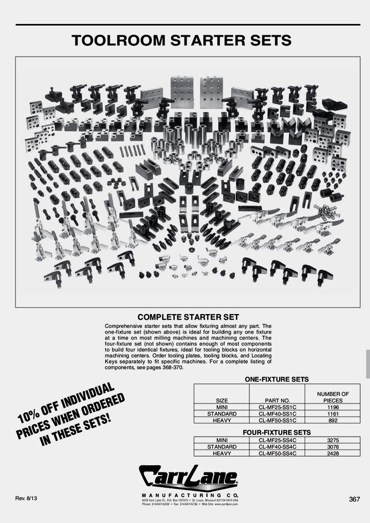
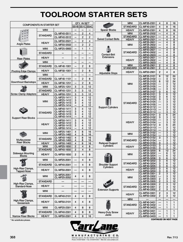
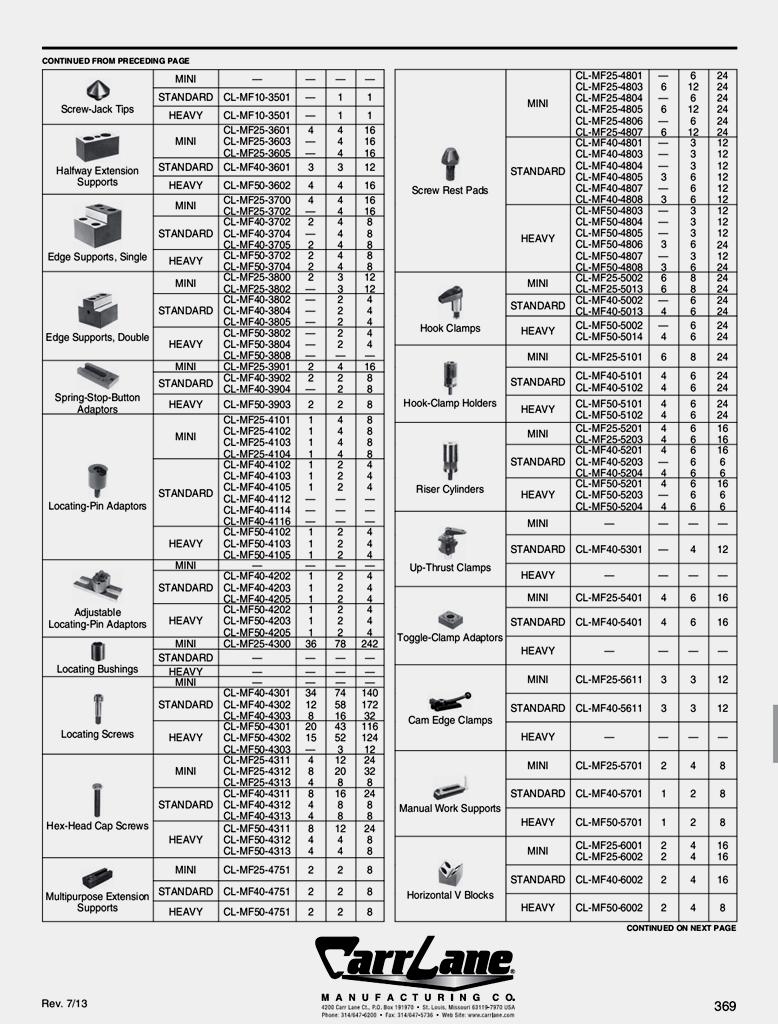
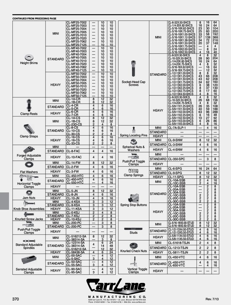
71 G: Tool room Starter Sets of CarrLane manufacturing company. 53
72 54
73 55
74 56
75 57
76 REFERENCES
77 REFERENCES [1] Rong; Y Kevin, Zhu; Y. Stephens, " Computer-Aided Fixture Design"; Marcel Dekker, Inc., USA, [2] Rong; Y. N., Huang; S. H., and Hou; Z. K., "Advanced Computeraided Fixture Design", Elsevier Inc., USA, [3] Miller; R., Miller; M. R., " Audel Automated Machines and Tool making All New 5th Edition", Wiley Publishing, Inc., USA, [4] Carr Lane Manufacturing Co. Staff, "Jig and Fixture Handbook", Carr Lane Manufacturing Co., USA, [5] Black; J. T., Kohser; R. A., "DeGarmo's Material and Processes in Manufacturing", 3rd Edition, John Wiley & Sons Inc, USA, [6] ignou is Indira Gandhi International Open University. [7] Segal; L., Romanescu; C. and Gojinetchi; N., " Application of Modular Fixturing For FMS", Buletinul Institutului Politehnic DIN IASI, University of Iasi, Romania, 2001 [8] Farhan; U. H., " An Integrated Computer-Aided Modular Fixture Design System for Machining Semi-Circular Parts", Master thesis submitted to the Faculty of Computing, Health and Science, Edith Cowan University, Australia, April [9] Yarwood; A., " An Introduction to AutoCAD 2004: 2D and 3D Design", Newnes An imprint of Elsevier, Great Britain, [10] Carr Lane Manufacturing Co., "Carr Lane Catalog USA". [11] Okolischan, R., "The 5 Steps of Fixture Design", Carr Lane manufacturing Co. 85
78 CAPSTONE DESIGN PROJECT PROJECT SUBMISSION
79 CAPSTONE DESIGN MANUAL CAPSTONE DESIGN PROJECT Project Submission and ABET Criterion 3 a-k Assessment Report Project Title: Fixtures Design Using Computer for Cylindrical Workpieces in Drilling Operations DATE: 16 / 7 / 1435 PROJECT ADVISOR: Team Leader: Team Members: Design Project Information Dr. Mahmoud Mohamed Atta Mahmoud Jaber Hadi Alassiri Ahmed Mohammd Ali Hammadi Hassan Jobran Al-Malki Majed Ali Almalki Saud Hassan Qurby Percentage of project Content- Engineering Science % 30% Percentage of project Content- Engineering Design % 70% Other content % All fields must be added to 100% Please indicate if this is your initial project declaration Project Initial Start Version or final project form Final Project Submission Version Do you plan to use this project as your capstone design project? Mechanism for Design Credit Projects in Engineering Design Independent studies in Engineering Engineering Special Topics Fill in how you fulfill the ABET Engineering Criteria Program Educational Outcomes listed below Outcome (a), An ability to apply knowledge of mathematics, science, and engineering fundamentals. Outcome (b). An ability to design and conduct experiments, and to critically analyze and interpret data. Please list here all subjects (math, science, engineering) that have been applied in your project. Example: let s consider CAFD (computer aided fixture design (machining operation, fixturing system, tolerance, engineering drawing) In this part, if the project included experimental work for validation and/or verification purposes, please indicate that. Prepared by Dr. REfaat Khater 2
80 CAPSTONE DESIGN MANUAL Outcome (c). An ability to design a system, component or process to meet desired needs within realistic constraints such as economic, Environmental, Social, political, ethical, health and safety, manufacturability, and sustainability Outcome (d). An ability to function in multi-disciplinary teams. Outcome (e). An ability to identify, formulate and solve engineering problems. Outcome (f). An understanding of professional and ethical responsibility. Outcome (g). An ability for effective oral and written communication. Outcome (h). The broad education necessary to understand the impact of engineering solutions in a global economics, environmental and societal context. Outcome (i). A recognition of the need for, and an ability to engage in life-long learning. Outcome (j). A knowledge of contemporary issues. Outcome (k). An ability to use the techniques, skills, and modern engineering tools necessary for engineering practice. All projects should include a design component. By design we mean both physical and non physical systems. Designing modular fixtures for drilling operations. The modular elements are collected from CarrLane manufacturing company catalog. The assembly sheets and the 3d geometrical model of the fixture are prepared. This outcome is achieved automatically by the fact that all projects composed of at least 3 students. However, if the project involved students from other departments, that would be a plus that is worth to be highlighted. In order to meet this specific outcome, it would help if you have a Problem Statement section in your project report. If not, then briefly highlight how the students were able identify, formulate and solve the project s problem. Here professional and ethical responsibility depends on the project context. Good report and good presentation will fulfill this outcome This outcome is usually fulfilled by highlighting the economic feasibility of the project, and emphasizing that the project would not harm the environment and does not negatively affect human subjects. This project help in reducing the lead time, human effort for machining operation in a certain company. Also, the project increase the accuracy and interchangeability of the product and increase the competitive of the company. This outcome is fulfilled by suggesting a plan for future studies and what else could be done based on the outcome of the current project. Extensive literature review by the students for the current state of the art will fulfill this outcome. List all technologies included in the project (hardware and software) Excel program and AutoCAD software. Prepared by Dr. REfaat Khater 3
81 CAPSTONE DESIGN MANUAL By signing below certify that this work is your own and fulfills the criteria described above Student Team Signatures Ahmed Mohammd Ali Hammadi Hassan Jobran Al-Malki Jaber Hadi Alassiri Majed Ali Almalki Saud Hassan Qurby Project Advisor Signature Dr. Mahmoud Mohamed Atta Mahmoud Date College Coordinator of Capstone Projects Approved By Prepared by Dr. REfaat Khater 4
82 الملخص العربى تصميم المثبتات باستخدام الحاسب االلى للمشغوالت االسطوانية فى عمليات الثقب المشكلة المشتركة بين المؤسسات الصناعية هى انتاج منتجات عالية الجودة فى وقت قصير و تكلفة منخفضة والتبادلية بين المنتجات. مثبتات المشغوالت هى الجزء الحرج فى نظم االنتاج حيث انها تؤثر فى دقة وتكلفة المنتج و الوقت المتقدم لعملية التشغيل. مرونة نظم التصنيع )لمواجهة التغير المستمر فى تصميم المنتجات و تقليل الوقت المتقدم و التنافسية بين المنتجات( يتواجه بعدم مرونة تصميم و تصنيع نظم التثبيت. المثبتات المعيارية هى احد اهم المثبتات المرنة بسبب عموميتها. تصميم المثبتات معقد جدا و مستهلك كبير للوقت. استخدام الحاسب اآللى يساعد على تسهيل عملية التصميم و التحليل للمثبتات المعيارية فهو يساعد على تقليل الوقت المتقدم و حساب البدائل المختلفة فى وقت قصير و توفير استخدام مهارات االخرين. خالل المشروع الحالى يستخدم الكمبيوتر لتصميم و اختيار اجزاء المثبت من بين االجزاء المعيارية )الممثلة فى اجزاء نظم الثبيت المعيارية ) للمشغوالت االسطوانية فى عمليات الثقب لثقوب موازية لمحور المشغول. فى النهاية يتم اعداد ورقة تجميع االجزاء المستخدمة فى المثبت. يستخدم الحاسب فى اعداد قاعدة بيانات للنماذج ثالثية االبعاد ألجزاء المثبتات المعيارية اعداد النماذج الهندسية النهائية لألجزاء المجمعة. و

 5341 ) 4153")
83 كلية الهندسة قسم الهندسة الميكانيكية استخدام احلاسب االىل فى تصميم املثبتات للمشغوالت االسطوانية فى عمليات الثقب طالب فريق العمل: مشرف المشروع : د/ احمد محمد على حمدى حسن جبران المالكى جابر هادى العسيرى ماجد على المالكى سعود حسن قربى محمود محمد عطا محمود تقرير مشروع التخرج مقدم للحصول على درجة البكالوريوس فى الهندسة الميكانيكية ) 5341 ) 4153 )رجب )مايو
The jigs and fixtures are the economical ways to produce a component in mass production system. These are special work holding and tool guiding device
 The jigs and fixtures are the economical ways to produce a component in mass production system. These are special work holding and tool guiding device Quality of the performance of a process largely influenced
Chapter 22 MACHINING OPERATIONS AND MACHINE TOOLS
 Chapter 22 MACHINING OPERATIONS AND MACHINE TOOLS Turning and Related Operations Drilling and Related Operations Milling Machining Centers and Turning Centers Other Machining Operations High Speed Machining
Manufacturing Processes (2), IE-352 Ahmed M El-Sherbeeny, PhD Spring Manual Process Planning
, IE-352 Ahmed M El-Sherbeeny, PhD Spring Manual Process Planning") Manufacturing Processes (2), IE-352 Ahmed M El-Sherbeeny, PhD Spring 2017 Manual Process Planning Chapter Outline 2 1. Introduction 2. Manual Process Planning 3. Process Plan 4. Part Features Identification
Manufacturing Processes (2), IE-352 Ahmed M El-Sherbeeny, PhD Spring 2017 Manual Process Planning Chapter Outline 2 1. Introduction 2. Manual Process Planning 3. Process Plan 4. Part Features Identification
Chapter 27 Workholding Devices for Machine Tools. Workholding Devices INTRODUCTION. MET Manufacturing Processes.
 MET 33800 Manufacturing Processes Chapter 27 Workholding Devices for Machine Tools Before you begin: Turn on the sound on your computer. There is audio to accompany this presentation. Chapter 27-1 Workholding
Jigs and fixtures are devices used to facilitate production work, making interchangeable pieces of work possible at a savings in cost of production.
 INTRODUCTION Over the past century, manufacturing has made considerable progress. New machine tools, high-performance cutting tools, and modern manufacturing processes enable today's industries to make
Work Holding Principles ITCD Rajeev Madhavan Nair
 Work Holding Principles ITCD 301-001 Work Holding One of the most important elements of the machining process Work holder includes all devices that hold, grip or chuck a work piece to perform a manufacturing
MFG 316 Chapter 4 //Workholding Principles
 Workholding Principles All devices that grip, hold, chuck, or retain a workpiece in order to perform a manufacturing operation. Force=hydraulic, pneumatic, electrical, mechanical Force multiplication by
Ahsanullah University of Science and Technology (AUST) Department of Mechanical and Production Engineering
 Department of Mechanical and Production Engineering") Ahsanullah University of Science and Technology (AUST) Department of Mechanical and Production Engineering LABORATORY MANUAL For the students of Department of Mechanical and Production Engineering 1 st
Ahsanullah University of Science and Technology (AUST) Department of Mechanical and Production Engineering LABORATORY MANUAL For the students of Department of Mechanical and Production Engineering 1 st
Jig and Fixture Design. Chapter 1: Types and Functions of Jigs and Fixtures
 Jig and Fixture Design Chapter 1: Types and Functions of Jigs and Fixtures Purpose of Tool Design Objectives: Provide simple, easy-to-operate tools for maximum efficiency Reduce manufacturing expenses
ME 2029 DESIGN OF JIGS AND FIXTURES NOTES UNIT I LOCATING AND CLAMPING PRINCIPLES
 ME 2029 DESIGN OF JIGS AND FIXTURES NOTES UNIT I LOCATING AND CLAMPING PRINCIPLES Locating and clamping are the critical functions of any work holder. As such, the fundamental principles of locating and
Technical Report Synopsis: Chapter 4: Mounting Individual Lenses Opto-Mechanical System Design Paul R. Yoder, Jr.
 Technical Report Synopsis: Chapter 4: Mounting Individual Lenses Opto-Mechanical System Design Paul R. Yoder, Jr. Introduction Chapter 4 of Opto-Mechanical Systems Design by Paul R. Yoder, Jr. is an introduction
TURNING BORING TURNING:
 TURNING BORING TURNING: FACING: Machining external cylindrical and conical surfaces. Work spins and the single cutting tool does the cutting. Done in Lathe. Single point tool, longitudinal feed. Single
Processing and Quality Assurance Equipment
 Processing and Quality Assurance Equipment The machine tool, the wash station, and the coordinate measuring machine (CMM) are the principal processing equipment. These machines provide the essential capability
International Journal of Science and Engineering Research (IJ0SER), Vol 3 Issue 3 March , (P) X
, Vol 3 Issue 3 March , (P) X") Design And Optimization Techniques Using In Turning Fixture M Rajmohan 1, K S Sakthivel 1, S Sanjay 1, A Santhosh 1, P Satheesh 2 1 ( UG Student ) 2 (Assistant professor)mechanical Department, Jay Shriram
Design And Optimization Techniques Using In Turning Fixture M Rajmohan 1, K S Sakthivel 1, S Sanjay 1, A Santhosh 1, P Satheesh 2 1 ( UG Student ) 2 (Assistant professor)mechanical Department, Jay Shriram
MANUFACTURING PROCESSES
 1 MANUFACTURING PROCESSES - AMEM 201 Lecture 5: Milling Processes DR. SOTIRIS L. OMIROU Milling Machining - Definition Milling machining is one of the very common manufacturing processes used in machinery
DESIGN AND MANUFACTURING OF MODIFIED ANGLE JIG TOOL
 DESIGN AND MANUFACTURING OF MODIFIED ANGLE JIG TOOL ABHIJIT TAGADE 1, NILESH NIRWAN 2, MANISH MISHRA 3 1. M.Tech student, Wainganga college of engineering, Nagpur (India) 2. Facutly, Wainganga college
Cincom Evolution Line
 Efficient Production Impressive Value Cincom Evolution Line Sliding Headstock Type Automatic CNC Lathe Cincom Evolution line from Citizen Introducing the K16E faster processing with outstanding ease-of-use.
Double Locating Fixed Vise w/.500 locating holes. Adjustable Vise w/.500 locating holes
 VISES VISES EZE-VISE TM MODULAR SETUPS Low profile, low cost modular vise set incorporates features found in higher priced products: positive location in 3-axes, raised locator surface to facilitate drilling
Locating Principles & Devices
 Locating Principles & Devices 1 LOCATING PRINCIPLES To position the work piece w.r.t. to tool, to ensure precision in machining Locating: dimensional and positional relationship b/w work piece and tool
Chapter 22: Turning and Boring Processes. DeGarmo s Materials and Processes in Manufacturing
 Chapter 22: Turning and Boring Processes DeGarmo s Materials and Processes in Manufacturing 22.1 Introduction Turning is the process of machining external cylindrical and conical surfaces. Boring is a
FACULTY OF ENGINEERING DESIGN AND PRODUCTION ENGINEERING DEPARTMENT. Credit Hour System Metrology Lab 1 MDP 240. Sine Bars. Metrology laboratory
 FACULTY OF ENGINEERING DESIGN AND PRODUCTION ENGINEERING DEPARTMENT Report On: Credit Hour System Metrology Lab 1 MDP 240 (13) Sine Bars Metrology laboratory Class No: B.N. Student Name Remark Signature
COMPUTER AIDED TRADITION JIGS AND FIXTURES DESIGN
 8 Military Technical College Kobry El-Kobbah, Cairo, Egypt. 17 th International Conference on Applied Mechanics and Mechanical Engineering. COMPUTER AIDED TRADITION JIGS AND FIXTURES DESIGN H.M.A Hussein
Contents. Notes on the use of this publication
 Contents Preface xxiii Scope Notes on the use of this publication xxv xxvi 1 Layout of drawings 1 1.1 General 1 1.2 Drawing sheets 1 1.3 Title block 2 1.4 Borders and frames 2 1.5 Drawing formats 2 1.6
Lathe. A Lathe. Photo by Curt Newton
 Lathe Photo by Curt Newton A Lathe Labeled Photograph Description Choosing a Cutting Tool Installing a Cutting Tool Positioning the Tool Feed, Speed, and Depth of Cut Turning Facing Parting Drilling Boring
Design of Fixture for Cross Hole Drilling of Flange-Yoke
 OPEN ACCESS International Journal Of Modern Engineering Research (IJMER) Design of Fixture for Cross Hole Drilling of Flange-Yoke Tushar D. Patil 1, Aditya V. Kavdikar 2, Anish T. Nadar 3, Gitesh M. Shirsat
STEVENS SUBPLATES. STEVENS ENGINEERING, INC. TOLL-FREE WEB FAX
 STEVENS SUBPLATES Spacing of hole patterns on Stevens accessories is identical to the pattern on Stevens Subplates. Insertion of the pull dowels thru bushed holes in the accessory into corresponding bushed
Trade of Toolmaking. Module 5: Press Tools, Jigs & Fixtures, Mouldmaking Unit 5: Jigs and Fixtures Phase 2. Published by
 Trade of Toolmaking Module 5: Press Tools, Jigs & Fixtures, Mouldmaking Unit 5: Jigs and Fixtures Phase 2 Published by SOLAS 2014 Unit 5 1 Table of Contents Document Release History... 3 Unit Objective...
MACHINE TOOL ACCESSORIES
 VERTICAL 5-C COLLET VISE SERIES 344: VERTICAL 3-C COLLET VISE SERIES 344: : 2-1/2 x 7-3/4 Height: 4 Small movement of lever opens or closes collet. 2030000 CAM OPERATED 5-C HORIZONTAL/VERTICAL COLLET FIXTURE
Competency, knowledge and skill areas often offer varying definitions. For purposes of this toolkit, NIMS defines them in the following manner:
 Toolkit Roadmap Title of report Credential name Narrative description of credential DEFINITION OF TERMS Competency, knowledge and skill areas often offer varying definitions. For purposes of this toolkit,
BHJ Products, Inc. Parts List & Instructions
 Product Name: Lifter-Tru Kit for General Motors LS V8 Page 1 of 5 Kit Contents: 2x End Plates 2x Threaded Adjustment Sleeves 1x Front Angle Bracket 2x M10-1.5 x 65 Hex Head Bolts * 2x Angle Adapter Blocks
Touch Probe Cycles itnc 530
 Touch Probe Cycles itnc 530 NC Software 340 420-xx 340 421-xx User s Manual English (en) 4/2002 TNC Models, Software and Features This manual describes functions and features provided by the TNCs as of
Typical Parts Made with These Processes
 Turning Typical Parts Made with These Processes Machine Components Engine Blocks and Heads Parts with Complex Shapes Parts with Close Tolerances Externally and Internally Threaded Parts Products and Parts
2014 / Universal 5 Axis Vise Positive high strength clamping close to the work-piece Obstruction free 5-axis machining
 21 / 215 Vischer & Bolli Machining and workholding Universal 5 Axis Vise Positive high strength clamping close to the work-piece Obstruction free 5-axis machining Obstruction free 5-side machining More
UNIT 4: (iii) Illustrate the general kinematic system of drilling machine and explain its working principle
 Illustrate the general kinematic system of drilling machine and explain its working principle") UNIT 4: Drilling machines: Classification, constructional features, drilling & related operations, types of drill & drill bit nomenclature, drill materials. Instructional Objectives At the end of this
UNIT 4: Drilling machines: Classification, constructional features, drilling & related operations, types of drill & drill bit nomenclature, drill materials. Instructional Objectives At the end of this
Materials Removal Processes (Machining)
") Chapter Six Materials Removal Processes (Machining) 6.1 Theory of Material Removal Processes 6.1.1 Machining Definition Machining is a manufacturing process in which a cutting tool is used to remove excess
Chapter Six Materials Removal Processes (Machining) 6.1 Theory of Material Removal Processes 6.1.1 Machining Definition Machining is a manufacturing process in which a cutting tool is used to remove excess
ADJUSTABLE CUTTING TOOL HOLDER INVENTORS WILLIAM LEE STEINHOUR Goneaway Lane Glenarm, Illinois DREW WEST
 Patent Application ADJUSTABLE CUTTING TOOL HOLDER INVENTORS WILLIAM LEE STEINHOUR 111 11946 Goneaway Lane Glenarm, Illinois 62536 DREW WEST 5201 South Hutchinson Ct. Battlefield, Missouri 69619 STEVE HONEYCUTT
Machine Tool Technology/Machinist CIP Task Grid
 1 Secondary Task List 100 ORIENTATION / SAFETY 101 Describe the Occupational Safety and Health Administration (OSHA) and its role in the machoning industry. 102 Identify & explain safety equipment and
Drilling. Drilling is the operation of producing circular hole in the work-piece by using a rotating cutter called DRILL.
 Drilling Drilling is the operation of producing circular hole in the work-piece by using a rotating cutter called DRILL. The machine used for drilling is called drilling machine. The drilling operation
InTurn TAIL STOCK II
 Specifications for the InTurn TAIL STOCK II accessory for the InTurn Indexing Turning 4 th axis The InTurn series is the only CNC mill accessory that provides both Indexing and coordinated 4 axis motion
JOB QUALIFICATION STANDARD (JQS)
") Occupation: Work Process: MACHINIST (CNC) CNC Setup Practical Hours: 2000 hrs. DOL Standard: CNC Setup: Apply a working knowledge in the setup of Computer Numerical Controls (CNC) machines that execute
Occupation: Work Process: MACHINIST (CNC) CNC Setup Practical Hours: 2000 hrs. DOL Standard: CNC Setup: Apply a working knowledge in the setup of Computer Numerical Controls (CNC) machines that execute
Cincom Evolution Line
 Efficient Production Impressive Value Cincom Evolution Line Sliding Headstock Type Automatic CNC Lathe Cincom Evolution line from Citizen Introducing the L20E meeting the needs of today Citizen s highly
CNC EXPANDING MANDRELS
 CNC EXPANDING MANDRELS ID CLAMPING OFFERS FULL OD PART ACCESS PARALLEL EXPANSION FOR OPTIMUM ACCURACY AND GRIP FORCE LARGE RANGE IN STOCK FOR IMMEDIATE SHIPMENT ROYAL CNC EXPANDING MANDRELS Rigid and Accurate
Designing for machining round holes
 Designing for machining round holes Introduction There are various machining processes available for making of round holes. The common processes are: drilling, reaming and boring. Drilling is a machining
Strands & Standards MACHINING 2
 Strands & Standards MACHINING 2 COURSE DESCRIPTION This course is the second in a sequence that will use technical knowledge and skills to plan and manufacture projects using machine lathes, mills, drill
Machine Tool Technology/Machinist CIP Task Grid Secondary Competency Task List
 1 100 ORIENTATION / SAFETY 101 Describe the Occupational Safety and Health Administration (OSHA) and its role in the machining industry. 2 2 2 1 0.5 102 Identify & explain safety equipment and procedures.
Touch Probe Cycles TNC 426 TNC 430
 Touch Probe Cycles TNC 426 TNC 430 NC Software 280 472-xx 280 473-xx 280 474-xx 280 475-xx 280 476-xx 280 477-xx User s Manual English (en) 6/2003 TNC Model, Software and Features This manual describes
LANDMARK UNIVERSITY, OMU-ARAN
 LANDMARK UNIVERSITY, OMU-ARAN LECTURE NOTE: DRILLING. COLLEGE: COLLEGE OF SCIENCE AND ENGINEERING DEPARTMENT: MECHANICAL ENGINEERING PROGRAMME: MECHANICAL ENGINEERING ENGR. ALIYU, S.J Course code: MCE
ROOP LAL Unit-6 Lathe (Turning) Mechanical Engineering Department
 Mechanical Engineering Department") Notes: Lathe (Turning) Basic Mechanical Engineering (Part B) 1 Introduction: In previous Lecture 2, we have seen that with the help of forging and casting processes, we can manufacture machine parts of
Notes: Lathe (Turning) Basic Mechanical Engineering (Part B) 1 Introduction: In previous Lecture 2, we have seen that with the help of forging and casting processes, we can manufacture machine parts of
IJRASET: All Rights are Reserved. UG Scholars, Department of Mechanical Engineering, SNS College of engineering, Coimbatore
 Fixture for bundle cutting of tubes and rods in saw cutting machine Mr.R.Pradeep Kumar 1, U.Rupesh Kiran 2, R. Sanjhay 3, G.Subramanian 4, R.Vijayakumar 5 1 Assistant Professor, Department of Mechanical
WHAT? WHERE? HOW?
 JIGS WHAT? WHERE? HOW? Introduction Mass production aims at high productivities to reduce unit cost and inter-changeabilites to facilitate easy assembly. Jigs are useful in mass production. They provide
5-axis clamping system compact
 5-axis clamping system compact 395 5-axis clamping system compact Function We are setting standards with the new KIPP 5-axis clamping system compact in this field. The system was specifically designed
bcprecision Devices, Inc. HYDRAULIC ARBORS AND CHUCKS
 UNEQUALED WORK HOLDING ACCURACY for: grinding; balancing; inspection; boring; facing; reaming; drilling; turning; shaving; hobbing and honing b SQUARENESS r CONCENTRICITY f PARALLELISM e ROUNDNESS v ALIGNMENT
Turning and Lathe Basics
 Training Objectives After watching the video and reviewing this printed material, the viewer will gain knowledge and understanding of lathe principles and be able to identify the basic tools and techniques
Machine Tool Technology/Machinist CIP Task Grid
 1 100 ORIENTATION / SAFETY 101 Describe the Occupational Safety and Health Administration (OSHA) and its role in the machining industry. 102 Identify & explain safety equipment and procedures. 103 Identify
DESIGN AND FABRICATION OF GRINDING ATTACHMENT FOR LATHE MACHINE TOOL
 DESIGN AND FABRICATION OF GRINDING ATTACHMENT FOR LATHE MACHINE TOOL Pratik Chavan 1, Sanket Desale 2, Ninad Kantela 3, Priyanka Thanage 4 Prasad Bari 5 1,2,3,4 B.E. Students, Fr. C Rodrigues Institute
Cincom Evolution Line
 Evolution and Innovation is the Future Sliding Headstock Type Automatic CNC Lathe Cincom Evolution Line Exceptional productivity and cost performance in a 5-axis ø20 mm machine Non-guide bushing spindle
Revised April Unit/Standard Number. High School Graduation Years 2016, 2017 and 2018
 Unit/Standard Number High School Graduation Years 2016, 2017 and 2018 Machine Tool Technology/Machinist CIP 48.0501 Task Grid Secondary Competency Task List 100 ORIENTATION / SAFETY 101 Describe the Occupational
Geometric Dimensioning and Tolerancing
 Geometric Dimensioning and Tolerancing (Known as GDT) What is GDT Helps ensure interchangeability of parts. Use is dictated by function and relationship of the part feature. It does not take the place
LocoGear. Technical Bulletin - 02 January 11, by LocoGear LIVE STEAM CASTINGS. Tech Bulletin - 02
 LIVE STEAM CASTINGS Tech Bulletin - 02 LocoGear Technical Bulletin - 02 January 11, 2003 2003 by LocoGear John D.L. Johnson 3879 Woods Walk Blvd. Lake Worth, FL 33467-2359 jjohnson@locogear.com www.locogear.com
JOB QUALIFICATION STANDARD (JQS)
") Occupation: Work Process: Maintenance Mechanic Machine Shop Practical Hours: 250 hrs. JOB QUALIFICATION STANDARD (JQS) DOL Standard: Manual Machining Fundamentals: Apply a working knowledge of metal removal
Occupation: Work Process: Maintenance Mechanic Machine Shop Practical Hours: 250 hrs. JOB QUALIFICATION STANDARD (JQS) DOL Standard: Manual Machining Fundamentals: Apply a working knowledge of metal removal
Drilling. Drilling is the operation of producing circular hole in the work-piece by using a rotating cutter called DRILL.
 Drilling Machine Drilling Drilling is the operation of producing circular hole in the work-piece by using a rotating cutter called DRILL. The machine used for drilling is called drilling machine. The drilling
Evaluation Instructions Machining Level II Milling: Precision Locations
 Evaluation Instructions Machining Level II Milling: Precision Locations General Instructions 1. Make sure that the candidate has his/her own copy of the part print, job instructions and understands the
Doler Self Colleting Machines*
 * P2 Drill with Variable Spacing Foot Light and compact - yet rigid and rugged Modular design - for easy setup and servicing Variety of spindle speeds and terminations to satisfy a wide range of applications
DEVELOPMENT OF MODULAR JIGS AND FIXTURE FOR CATIA
 UNIVERSITI TEKNIKAL MALAYSIA MELAKA DEVELOPMENT OF MODULAR JIGS AND FIXTURE FOR CATIA Thesis submitted in accordance with the partial requirements of the Universiti Teknikal Malaysia Melaka for the Bachelor
Design a drill jig for drilling 4 holes in the following component.
 Design a drill jig for drilling 4 holes in the following component. Design procedure for Jig a. Selection of Jig A leaf (or) latch jig is selected to accomplish this component. The leaf is hinged on one
Datum reference frame Position and shape tolerances Tolerance analysis
 Datum reference frame Position and shape tolerances Tolerance analysis Šimon Kovář Datum reference frame Datum reference frames are typically for 3D. A typical datum reference frame is made up of three
CHAPTER 6 EXPERIMENTAL VALIDATION AND RESULTS AND DISCUSSIONS
 119 CHAPTER 6 EXPERIMENTAL VALIDATION AND RESULTS AND DISCUSSIONS 6.1 CNC INTRODUCTION The CNC systems were first commercially introduced around 1970, and they applied the soft-wired controller approach
SHAPER, MILLING AND GEAR CUTTING MACHINES
 UNIT 3 SHAPER, MILLING AND GEAR CUTTING MACHINES 1. Compare hydraulic shaper with mechanical shaper? SL.NO Hydrulic shaper Mechanical shaper 1. smooth cutting operation Rough and noisy cutting operation
Name: Machine Tool Technology ( )
") Name: Machine Tool Technology (58.0501) Directions: Evaluate the student by checking the appropriate number to indicate the degree of competency. Rating Scale (0-6): 0 No Exposure no experience/knowledge
Name: Machine Tool Technology (58.0501) Directions: Evaluate the student by checking the appropriate number to indicate the degree of competency. Rating Scale (0-6): 0 No Exposure no experience/knowledge
Introduction to Machining: Lathe Operation
 Introduction to Machining: Lathe Operation Lathe Operation Lathe The purpose of a lathe is to rotate a part against a tool whose position it controls. It is useful for fabricating parts and/or features
POS Perkins Statewide Articulation Agreement Documentation Coversheet
 POS Perkins Statewide Articulation Agreement Documentation Coversheet Student Name: Secondary School Name: Secondary School Address: CTE Program of Study: CIP # CIP Program Name Grade 9 1. CAREER AND TECHNICAL
DOVETAIL FIXTURES. What is Raptor? Strong by design. ADAPTERS & RISERS. Less waste and easy setup. Tested and Proven. SPARE KITS CUTTERS &
 What is Raptor? One of the challenges to manufacturing with 4 and 5-Axis CNC Machines has traditionally been how to hold the workpiece. We ve solved this problem for you with Raptor workholding products.
IED Detailed Outline. Unit 1 Design Process Time Days: 16 days. An engineering design process involves a characteristic set of practices and steps.
 IED Detailed Outline Unit 1 Design Process Time Days: 16 days Understandings An engineering design process involves a characteristic set of practices and steps. Research derived from a variety of sources
Chapter 2: Dimensioning Basic Topics Advanced Topics Exercises
 Chapter 2: Dimensioning Basic Topics Advanced Topics Exercises Dimensioning: Basic Topics Summary 2-1) Detailed Drawings 2-2) Learning to Dimension 2-3) Dimension Appearance and Techniques. 2-4) Dimensioning
Improving Spindle Up-time with the Right Workholding. Michael Gaunce Group Manager, Stationary Workholding
 Improving Spindle Up-time with the Right Workholding Michael Gaunce Group Manager, Stationary Workholding Agenda Importance of Workholding & What IS Workholding Scope & Definitions Part Clamping Part Density
Mill Safety Competencies
 Mill Safety Competencies The following list of competencies is presented to ensure the contents of a training program from a perspective of safety. Additional instruction in actual tool use would augment
A study of accuracy of finished test piece on multi-tasking machine tool
 A study of accuracy of finished test piece on multi-tasking machine tool M. Saito 1, Y. Ihara 1, K. Shimojima 2 1 Osaka Institute of Technology, Japan 2 Okinawa National College of Technology, Japan yukitoshi.ihara@oit.ac.jp
CHAPTER 01 PRESENTATION OF TECHNICAL DRAWING. Prepared by: Sio Sreymean
 CHAPTER 01 PRESENTATION OF TECHNICAL DRAWING Prepared by: Sio Sreymean 2015-2016 Why do we need to study this subject? Effectiveness of Graphics Language 1. Try to write a description of this object. 2.
Perkins Statewide Articulation Agreement. Documentation item: Secondary Competency Task List Coversheet
 Perkins Statewide Articulation Agreement Documentation item: Secondary Task List Coversheet The Secondary School agrees to: A. Implement the approved PDE Program(s) of Study. B. Provide assessment of student
Lecture 3 2: General Purpose Machine Tools: Drilling Machines and Operations Dr. Parviz Kahhal
 Lecture 3 2: General Purpose Machine Tools: Drilling Machines and Dr. Parviz Kahhal Drilling Operation Drilling is a process used extensivelybywhichthroughorblind holes are originated or enlarged in a
Universal 5 Axis Vise Positive high strength clamping close to the work-piece Obstruction free 5-axis machining
 Machining and workholding Universal 5 Axis Vise Positive high strength clamping close to the work-piece Obstruction free 5-axis machining Obstruction free 5-side machining More and more companies are investing
Design of Jig for Coordinate Measuring Machine
 Journal of Mechanical Engineering Vol SI 5(5), 97-107, 2018 Design of Jig for Coordinate Measuring Machine Norasikin Hussin, Dzullijah Ibrahim*, N. H. Mohd Yahya, Nor Izlan Zulkkhiflee Faculty of Mechanical
Lathes. CADD SPHERE Place for innovation Introduction
 Lathes Introduction Lathe is one of the most versatile and widely used machine tools all over the world. It is commonly known as the mother of all other machine tool. The main function of a lathe is to
MACHINE TOOLS GRINDING MACHINE TOOLS
 MACHINE TOOLS GRINDING MACHINE TOOLS GRINDING MACHINE TOOLS Grinding in generally considered a finishing operation. It removes metal comparatively in smaller volume. The material is removed in the form
Procedure for Longworth Chuck construction
 Procedure for Longworth Chuck construction Overall construction The Longworth chuck is composed of three major components. Connected to the lathe spindle is some device that fastens to the first of two
Purdue AFL. CATIA CAM Process Reference Rev. B
 Purdue AFL CATIA CAM Process Reference Rev. B Revision Notes Revision - of this document refers to the CATIA v5r21 deployment of the AFL CATIA Environment. All information contained in this reference document
Entry Level Assessment Blueprint Precision Machining
 Blueprint Precision Machining Test Code: 4152 / Version: 01 Specific Competencies and Skills Tested in this Assessment: Organization and Shop Practices Demonstrate safe work habits and operating procedures
Portable Milling Machines
 Versatile and Accurate Mill X Y Z W Diameter Shank 18 1.0 Z X 57. 5. 30 1.0 Z X 36 76 5. 30 6 6 6.0 6Z X 36 76 36 8 8 8.0 8Z X 91. 6 8 8 8.0 8Z X 7 165.6 80 16 16 16.0 16Z X 96 03 06. 06. 06. The new TCM
Features of TOOLFAST Clamping Devices and Clamping Elements
 PART I CLAMPING DEVICES & CLAMPING ELEMENTS INTRODUCTION In the following pages of this part of catalogue, different types & sizes of clamping devices and clamping elements manufactured by us are illustrated.
Student, Department of Mechanical Engineering, Knowledge Institute of Technology, Salem, Tamilnadu (1,3)
") International Journal of Scientific & Engineering Research, Volume 7, Issue 5, May-2016 11 Combined Drilling and Tapping Machine by using Cone Mechanism N.VENKATESH 1, G.THULASIMANI 2, S.NAVEENKUMAR 3,
International Journal of Scientific & Engineering Research, Volume 7, Issue 5, May-2016 11 Combined Drilling and Tapping Machine by using Cone Mechanism N.VENKATESH 1, G.THULASIMANI 2, S.NAVEENKUMAR 3,
SALE SALE SALE palmgren.com chhanson.com SWIVEL BASES SPEED HANDLES
 FRIENDS OF PALMGREN SPECIAL OFFERS WORKHOLDING S EVENT DUAL FORCE PRECISION MACHINE VISES Palmgren s Dual Force line of machine vises are all designed for precision part clamping and are ideal for use
FEATURE BIG NICHE THE
 THE BIG NICHE Expertise and the right equipment for machining large components for oilfield and other industries enable this shop to succeed despite fluctuating economic conditions. BY DEREK KORN 66 MMS
Module 2. Milling calculations, coordinates and program preparing. 1 Pepared By: Tareq Al Sawafta
 Module 2 Milling calculations, coordinates and program preparing 1 Module Objectives: 1. Calculate the cutting speed, feed rate and depth of cut 2. Recognize coordinate 3. Differentiate between Cartesian
Machinist NOA (1998) Subtask to Unit Comparison
 Subtask to Unit Comparison") Machinist NOA (1998) Subtask to Unit Comparison NOA Subtask Task 1 Demonstrates safe working practices. 1.01 Recognizes potential health and safety hazards. A1 Safety in the Machine Shop 1.02 Recognizes
Machinist NOA (1998) Subtask to Unit Comparison NOA Subtask Task 1 Demonstrates safe working practices. 1.01 Recognizes potential health and safety hazards. A1 Safety in the Machine Shop 1.02 Recognizes
Fixed Headstock Type CNC Automatic Lathe
 Fixed Headstock Type CNC Automatic Lathe The BNA series packs sophisticated functions and high accuracy into a space-saving compact body. The BNA series aims to set the new standard for machines for cutting
MACHINIST TECHNICIAN - LATHE (582)
") DESCRIPTION Students will demonstrate technical knowledge and skills to plan, manufacture, assemble, test products, and modify metal parts using machine shop and CNC processes in support of other manufacturing,
DESCRIPTION Students will demonstrate technical knowledge and skills to plan, manufacture, assemble, test products, and modify metal parts using machine shop and CNC processes in support of other manufacturing,
FixLogix CMM Fixture System Instructions
 FixLogix CMM Fixture System Instructions FixLogix uses t-slot technology to provide simple fixture construction. Components are locked onto the plate or linear frames using FixLogix t-nuts. This design
LOC ATING COMPONENTS. Locating Components
 Adjustable Jack Screws... 212 Adjustable Locating Buttons... 212 Alloy Steel Pull Dowel Pins...198 199 Bullet Nose Dowels... 219 Bullet Nose Pins... 220 Drift Handles... 213 Fixture Jacks... 212 Fixture
Block Delete techniques (also called optional block skip)
") Block Delete techniques (also called optional block skip) Many basic courses do at least acquaint novice programmers with the block delete function As you probably know, when the control sees a slash code
Block Delete techniques (also called optional block skip) Many basic courses do at least acquaint novice programmers with the block delete function As you probably know, when the control sees a slash code
Special Purpose Fixture
 ASSEMBLY FIXTURES Assembly fixtures Simple Fixtures Features Used in single or small lot production. These are universal fixtures. Usually they have machined locating surfaces and holes to receive fastening