Use of Anaerobic Adhesive for Prevailing Torque Locking Feature on Threaded Product
|
|
|
- Lenard Cooper
- 5 years ago
- Views:
Transcription

. Graduate Theses and Dissertations. http://scholarcommons.usf.edu/etd/5700 This Thesis is brought to you for free and open access by the Graduate School at Scholar Commons.")
1 University of South Florida Scholar Commons Graduate Theses and Dissertations Graduate School January 2015 Use of Anaerobic Adhesive for Prevailing Torque Locking Feature on Threaded Product Alan Hernandez University of South Florida, Follow this and additional works at: Part of the Aerospace Engineering Commons, and the Mechanical Engineering Commons Scholar Commons Citation Hernandez, Alan, "Use of Anaerobic Adhesive for Prevailing Torque Locking Feature on Threaded Product" (2015). Graduate Theses and Dissertations. This Thesis is brought to you for free and open access by the Graduate School at Scholar Commons. It has been accepted for inclusion in Graduate Theses and Dissertations by an authorized administrator of Scholar Commons. For more information, please contact
2 Use of Anaerobic Adhesive for Prevailing Torque Locking Feature on Threaded Product by Alan Hernandez A thesis submitted in partial fulfillment of the requirements for the degree of Master of Science in Mechanical Engineering Department of Mechanical Engineering College of Engineering University of South Florida Major Professor: Daniel P. Hess, Ph.D. Wenjun Cai, Ph.D. Nathan Crane, Ph.D. Date of Approval: June 29, 2015 Keywords: Running Torque, Locking Torque, Preload, Fastener, Reuse, Removal Torque Copyright 2015, Alan Hernandez
3 DEDICATION I would like to dedicate this thesis to my family and friends. I would like to especially dedicate it too my mother and father, Elsa and Mario Hernandez, for their encouragement and support throughout my educational career. My brother, Michael R. Hernandez, which has motivated me when I needed it most. I also dedicate this thesis to Anayamille Alvarado, for being by my side through most of my educational career and ensuring I do my best at everything I do.
4 ACKNOWLEDGMENTS I would like to give a special thanks to my major professor Daniel P. Hess, Ph.D., for seeing the potential that I contain and for his wisdom and guidance throughout my educational career. I would also like to thank the mechanical engineering department of University of South Florida, for all the help and resources provided. Also I would like to thank Joseph Gombar from Aerolyusa Inc. for the support with the aerospace fasteners. A special thanks to Goddard Space Flight Center for all of the support they provided.
5 TABLE OF CONTENTS LIST OF TABLES... iv LIST OF FIGURES... vi ABSTRACT... ix CHAPTER 1: INTRODUCTION AND BACKGROUND... 1 CHAPTER 2: TESTING Materials Threaded Fasteners Plain Grade Cap Screws Hex Nuts Flat Washers Yellow-Zinc Grade Cap Screws Hex Nuts Flat Washers A Cap Screws Hex Nuts Flat Washers Anaerobic Adhesive Equipment Ultrasonic Cleaner Torque Wrench Calibration of Torque Wrenches Fixtures Unseated State Fixture Seated State Fixtures Preparing the Test Specimen Inspection Process Cleaning Process Cleaning Process for Unseated State Tests Cleaning Process for Seated State Tests...17 i
6 Cleaning Process of Fixture for Seated State Cleaning Process of Threaded Fasteners for Seated State Unseated State Test Procedure Initial Unseated State Preparation of Test Specimens for Initial Unseated State Test Procedure for Initial Unseated State Reuse of the Unseated State Preparation of Test Specimens for Reuse of the Unseated State Test Procedure for Reuse of the Unseated State Reuse of the Unseated State Adding Anaerobic Adhesive Preparation of Test Specimens for Reuse of Unseated State Adding Anaerobic Adhesive Test Procedure for Reuse of Unseated State Adding Anaerobic Adhesive Seated State Procedure Initial Seated State Preparation of Test Specimens for Initial Seated State Test Procedure for Initial Seated State Re-Use of the Seated State Preparation of Test Specimens for Re-Use of the Seated State Test Procedure for Re-Use of the Seated State Reuse of the Seated State Adding Anaerobic Adhesive Preparation of Test Specimens for Reuse of the Seated State Adding Anaerobic Adhesive Test Procedure for Reuse of the Seated State Adding Anaerobic Adhesive Test Matrix CHAPTER 3: RESULTS Results for Unseated State Unseated Plain Grade Unseated Plain Grade 8 Loctite 222MS Unseated Plain Grade 8 Loctite Unseated Plain Grade 8 Loctite Unseated Yellow-Zinc Grade Unseated Yellow-Zinc Grade 8 Loctite 222MS Unseated Yellow-Zinc Grade 8 Loctite Unseated Yellow-Zinc Grade 8 Loctite ii
7 3.1.3 Unseated A Unseated A-286 Loctite 222MS Unseated A-286 Loctite Unseated A-286 Loctite Results for Seated State Seated Plain Grade Seated Plain Grade 8 Loctite 222MS Seated Plain Grade 8 Loctite Seated Plain Grade 8 Loctite Seated Yellow-Zinc Grade Seated Yellow-Zinc Grade 8 Loctite 222MS Seated Yellow-Zinc Grade 8 Loctite Seated Yellow-Zinc Grade 8 Loctite Seated A Seated A-286 Loctite 222MS Seated A-286 Loctite Seated A-286 Loctite CHAPTER 4: DISCUSSIONS Discussions for Unseated State Discussions for Unseated Plain Grade Discussions for Unseated Yellow-Zinc Grade Discussion for Unseated A Discussions for Seated State Discussions for Seated Plain Grade Discussions for Seated Yellow-Zinc Grade Discussions for Seated A Overall Discussion CHAPTER 5: CONCLUSIONS REFERENCES iii
8 LIST OF TABLES Table 1 Plain grade 8 cap screw specifications Table 2 Plain grade 8 hex nut specifications Table 3 USS steel flat washer specifications Table 4 Yellow-Zinc grade 8 cap screw specifications Table 5 Yellow-Zinc grade 8 hex nut specifications Table 6 Yellow-Zinc grade 8 flat washer specifications Table 7 A-286 cap screw specifications Table 8 A-286 hex nut specifications Table 9 A-286 flat washer specifications Table 10 Loctite 222MS specifications Table 11 Loctite 242 specifications Table 12 Loctite 243 specifications Table in-lbs. dial torque wrench specifications Table in-lbs. dial torque wrench specifications Table 15 Calibration verification of torque wrenches Table 16 Test matrix Table 17 Unseated plain grade 8 percent within prevailing torque specification Table 18 Unseated yellow-zinc grade 8 test results Table 19 Unseated A-286 test results Table 20 Seated plain grade 8 results iv
9 Table 21 Seated yellow-zinc test results Table 22 Seated A-286 test results Table 23 Configurations with 100% pass rate Table 24 Configurations that exceeded the specifications v
10 LIST OF FIGURES Figure 1 Calibration of torque wrench Figure 2 Top view for seated state fixtures Figure 3 Front view of seated state fixtures Figure 4 Side view of seated state fixtures Figure 5 Threaded fastener clamped on table vise Figure 6 Seated state fixture fastener install Figure 7 Clamping the head of the cap screw with a table vise Figure 8 Initial unseated plain grade 8 Loctite 222MS Figure 9 Unseated plain grade 8 Loctite 222MS reuse Figure 10 Unseated plain grade 8 Loctite 222MS reuse adding anaerobic adhesive Figure 11 Initial unseated plain grade 8 Loctite Figure 12 Unseated plain grade 8 Loctite 242 reuse Figure 13 Unseated plain grade 8 Loctite 242 reuse adding anaerobic adhesive Figure 14 Initial unseated plain grade 8 Loctite Figure 15 Unseated plain grade 8 Loctite 243 reuse Figure 16 Unseated plain grade 8 Loctite 243 reuse adding anaerobic adhesive Figure 17 Initial unseated yellow-zinc grade 8 Loctite 222MS Figure 18 Unseated yellow-zinc grade 8 Loctite 222MS reuse Figure 19 Unseated yellow-zinc grade 8 Loctite 222MS reuse adding anaerobic adhesive Figure 20 Initial unseated yellow-zinc grade 8 Loctite vi
11 Figure 21 Unseated yellow-zinc grade 8 Loctite 242 reuse Figure 22 Unseated yellow-zinc grade 8 Loctite 242 reuse adding anaerobic adhesive Figure 23 Initial unseated yellow-zinc grade 8 Loctite Figure 24 Unseated yellow-zinc grade 8 Loctite 243 reuse Figure 25 Unseated yellow-zinc grade 8 Loctite 243 reuse adding anaerobic adhesive Figure 26 Initial unseated A-286 Loctite 222MS Figure 27 Unseated A-286 Loctite 222MS reuse Figure 28 Unseated A-286 Loctite 222MS reuse adding anaerobic adhesive Figure 29 Initial unseated A-286 Loctite Figure 30 Unseated A-286 Loctite 242 reuse Figure 31 Unseated A-286 Loctite 242 reuse adding anaerobic adhesive Figure 32 Initial unseated A-286 Loctite Figure 33 Unseated A-286 Loctite 243 reuse Figure 34 Unseated A-286 Loctite 243 reuse adding anaerobic adhesive Figure 35 Initial seated plain grade 8 Loctite 222MS Figure 36 Seated plain grade 8 Loctite 222MS reuse Figure 37 Seated plain grade 8 Loctite 222MS reuse adding anaerobic adhesive Figure 38 Initial seated plain grade 8 Loctite Figure 39 Seated plain grade 8 Loctite 242 reuse Figure 40 Seated plain grade 8 Loctite 242 reuse adding anaerobic adhesive Figure 41 Initial seated plain grade 8 Loctite Figure 42 Seated plain grade 8 Loctite 243 reuse Figure 43 Seated plain grade 8 Loctite 243 reuse adding anaerobic adhesive vii
12 Figure 44 Initial seated yellow-zinc grade 8 Loctite 222MS Figure 45 Seated yellow-zinc grade 8 Loctite 222MS reuse Figure 46 Seated yellow-zinc grade 8 Loctite 222MS reuse adding anaerobic adhesive Figure 47 Initial seated yellow-zinc grade 8 Loctite Figure 48 Seated yellow-zinc grade 8 Loctite 242 reuse Figure 49 Seated yellow-zinc grade 8 Loctite 242 reuse adding anaerobic adhesive Figure 50 Initial seated yellow-zinc grade 8 Loctite Figure 51 Seated yellow-zinc grade 8 Loctite 243 reuse Figure 52 Seated yellow-zinc grade 8 Loctite 243 reuse adding anaerobic adhesive Figure 53 Initial seated A-286 Loctite 222MS Figure 54 Seated A-286 Loctite 222MS reuse Figure 55 Seated A-286 Loctite 222MS second reuse Figure 56 Initial seated A-286 Loctite Figure 57 Seated A-286 Loctite 242 reuse Figure 58 Seated A-286 Loctite 242 reuse adding anaerobic adhesive Figure 59 Initial seated A-286 Loctite Figure 60 Seated A-286 Loctite 243 reuse Figure 61 Seated A-286 Loctite 243 reuse adding anaerobic adhesive viii
13 ABSTRACT The purpose of this research is to determine if anaerobic adhesive can be used as a prevailing torque locking feature. Maintaining preload in critical joints is the usual standard that anaerobic adhesives are held to in aerospace and other industry. To test if anaerobic adhesive can be used as a prevailing torque locking feature a test procedure was developed and implemented to measure the removal torque of threaded fasteners after an allotted cure time. In total, 191 threaded fasteners of different material and coatings were tested in the unseated and seated states with various strengths and varieties of anaerobic adhesive. A series of three tests were conducted: initial use, reuse with no added anaerobic adhesive, and a third test with added product to the bolt and nut to see how removal torque would behave in these conditions. It was found that using anaerobic adhesive as a prevailing torque locking feature is viable in many cases. No published work to date analyzes anaerobic adhesive at the standard of a prevailing torque locking feature. ix
14 CHAPTER 1: INTRODUCTION AND BACKGROUND The loosening of threaded fasteners in critical applications is a major concern still today though there are many devices and standards that help prevent threaded fasteners from disassembling. The two most common devices used on threaded fasteners are mechanical locking features and prevailing torque locking features. A mechanical locking feature is one that employs non-friction methods to hold the threaded fastener together to maintain preload [1]. This type of locking feature usually involves a cotter pin or safety wire. A prevailing torque locking feature is one that relies on friction but independent of preload to resist disassembly of a threaded fastener [1]. Some examples of prevailing torque locking features are deformed thread nuts and nylon lock nuts. Another form of providing a locking feature to threaded fasteners is with thread locking anaerobic adhesives. Thread locking anaerobic adhesives are single component anaerobic adhesives that consist of a resin that hardens to a solid in the presence of metal ions and absence of oxygen [2]. As an anaerobic adhesive cures the gap between the threads become completely filled. In filling the gaps, thread friction increases causing it to work as a locking feature. A potential issue with using an anaerobic adhesive is that curing is not always guaranteed since curing can be affected by the type of material the threaded fastener is made of or coated with. Knowing the material of the threaded fastener is important for the reason the anaerobic adhesive performs differently between active and inactive metals. Inactive metals are low in metal ions which are necessary to promote curing with anaerobic adhesives. With inactive metals it is necessary to apply an activator to the threads to improve anaerobic adhesive curing [2]. 1
15 Inactive metals consist of stainless steel, zinc, magnesium, cadmium, anodized aluminum and passivated titanium [3]. Recently, a method to validate if sufficient curing has occurred has been developed but is not yet commonly used in practice [4]. This method uses a test removal torque that is slightly less than the breakaway torque so the locking is not destroyed. Before the development of this method there was no direct way to assess that the anaerobic adhesive has cured. The aerospace industry has preferred using prevailing torque locking features for the reason that they can be easily validated during installation and there are standards and specifications associated with prevailing torque locking features [5, 6, 7, 8, 9, 10]. Another reason is uncured anaerobic adhesives can off-gas which can contaminate other components in space applications. When anaerobic adhesive is used in the aerospace industry it is held to the same standard as a mechanical locking feature which is to maintain preload on joints [1]. What if anaerobic adhesive is not held to the standard as a thread locker for preload critical joints but to the standard of a prevailing torque locking feature? Some work using anaerobic adhesive as a prevailing torque locking feature has been performed [11, 12] but no published research currently exist. Anaerobic adhesive was used to repair the worn prevailing torque locking features in inserts on the windshield of a space shuttle [11, 12]. Using anaerobic adhesive to repair the locking feature was chosen over replacing inserts in the shuttles structure because replacing the inserts would have damaged or destroyed the structure. The purpose of this research is to test if using anaerobic adhesive can be used as a prevailing torque locking feature. This was done by testing a variety of non-aerospace and aerospace threaded fastener with a variety of anaerobic adhesives. The threaded fasteners will be 2
16 tested in the unseated and seated state. Unseated state means that the threaded fastener does not contain any preload or better said does not clamp the components. As for the seated state, the fasteners will be preloaded to a designated torque. A procedure for preparing the threaded fasteners for testing and how to test the threaded fasteners will be defined for repeatability of the data collected. After the data is collected, presented results are discussed to assess if anaerobic adhesive can be used as a prevailing locking feature within the specification. 3
17 CHAPTER 2: TESTING The goal of this study is to see if an anaerobic adhesive can be used as an in specification prevailing torque locking feature. This is determined by testing a variety of aerospace and nonaerospace grade threaded fasteners in the unseated and seated state. For both testing states the reuse of anaerobic adhesive is explored. The same threaded fastener is tested twice in reuse. For the first reuse the hex nut is completely removed and then placed at the same location where it previously cured at. For the second reuse the nut is completely removed but anaerobic adhesive is added to the cap screw and hex nut. The reasoning behind testing the reuse of threaded fasteners containing anaerobic adhesive is to comprehend the effects of the adhesive under these conditions. 2.1 Materials Threaded Fasteners All threaded fasteners used consist of ¼-28 thread size with differing root radii. For the non-aerospace grade fasteners the thread type is ¼-28 UNF, while for the aerospace grade fastener the thread type is ¼-28 UNJF which has a rounded root radius. The nuts used are plain hex nuts for the reason that they resemble lock nuts with worn prevailing torque locking feature. By using plain hex nuts this gives the ability to explore anaerobic adhesive as repair method for worn mechanical prevailing torque locking features, as well as, using plain hex nuts with anaerobic adhesive as a prevailing torque locking feature. The advantage of using just a plain hex nut with anaerobic adhesive as a prevailing torque locking feature is the reduced cost of materials during assembly and also the ability to reuse the threaded fastener by just adding 4
18 anaerobic adhesive. In total 191 cap screws, 191 hex nuts, and 174 flat washers were tested. The specifications for these products are provided in the following subsections Plain Grade 8 The specifications for the plain grade 8 threaded fasteners are provided in Tables 1-3. When referring to the cap screws, hex nuts, and flat washers as plain, it is describing that the products are as-manufactured which are black in color Cap Screws Table 1 Plain grade 8 cap screw specifications. Manufacturer Material Properties Dimension and Tolerances Coating Type Thread Type Thread Length Lot # Plain Grade 8 Cap Screw Nucor Fasteners Covered in SAE J429 Meets ASME (ANSI) B Plain ¼ -28 UNF 1-¼ inches A Hex Nuts Table 2 Plain grade 8 hex nut specifications. Manufacturer Material Properties Dimension and Tolerances Coating Type Thread Type Lot # Plain Grade 8 Hex Nut Fabory Covered in SAE J995 Meets ASME (ANSI) B Plain ¼ -28 UNF n
19 Flat Washers Table 3 USS steel flat washer specifications. USS Steel Flat Washer Manufacturer Fabory Material Properties Covered in ASME B Dimension and Tolerances Meets ASME (ANSI) B Coating Type Plain Lot # Yellow-Zinc Grade 8 The coating on the caps screws, hex nuts, and flat washers are yellow-zinc. Yellow-zinc is the most common type of finish found on threaded product. Plating the threaded fasteners with this type of coating provides resistance to corrosion. Tables 4-6 provides the specifications for the yellow-zinc grade 8 products Cap Screws Table 4 Yellow-Zinc grade 8 cap screw specifications. Yellow-Zinc Grade 8 Cap Screw Manufacturer Brighton Best Material Properties Covered in SAE J429 Dimension and Tolerances Meets ASME (ANSI) B Coating Type ASTM F1941 FeZn5C Thread Type ¼ -28 UNF Thread Length 1-¼ inches Lot #
20 Hex Nuts Table 5 Yellow-Zinc grade 8 hex nut specifications. Manufacturer Material Properties Dimension and Tolerances Coating Type Thread type Lot # Yellow-Zinc Grade 8 Hex Nut Fabory Covered in SAE J995 Meets ASME (ANSI) B Yellow Zinc Plating ¼ -28 UNF GD Flat Washers Table 6 Yellow-Zinc grade 8 flat washer specifications. Yellow-Zinc Grade 8 Flat Washer Manufacturer Master Products Material Properties Covered in ASTM F436 Dimension and Tolerances Meets ASME (ANSI) B Coating Type Yellow Zinc Plating ASTM F436 Lot # A-286 A-286 is a very common stainless steel used for aerospace threaded fasteners. The caps screws, hex nuts, and flat washers contain a passivate finish. The passivate finish enhances stainless steels natural ability to resist corrosion. In Tables 7-9 the specifications for the cap screws, hex nuts, and flat washers are given. 8
21 Cap Screws Table 7 A-286 cap screw specifications. A-286 Cap Screw Vendor Aerolyusa Manufacturer 3V Fasteners Part # NAS1004-1A Material Properties AMS 5731L Heat Treatment AMS 2759/3D Dimension and Tolerances Meets MIL-S-8879 Coating Type Passivate AMS 2700B Met. I TY II Thread type ¼ -28 UNJF-3A Mfg Lot # Hex Nuts Table 8 A-286 hex nut specifications. A-286 Hex Nut Vendor Aerolyusa Manufacturer Automatic Screw Machine Part # MS Material Properties AMS 5737P Heat Treatment AMS5737P Dimension and Tolerances Meets MIL-S-8879 Coating Type Passivate per specification Thread type ¼ -28 UNJF-3B Mfg Lot #
22 Flat Washers Table 9 A-286 flat washer specifications. Vendor Manufacturer Part # Material Properties Heat Treatment Dimension and Tolerances Coating Type A-286 Flat Washer Aerolyusa Anillo Industries NAS1149E0432R AMS 5525 Rev. J AMS2759 NAS1149E0432R Passivate AMS-2700 Met. I TY VI Anaerobic Adhesive Low and medium strength anaerobic adhesives are used in this work for the reason that high strength anaerobic adhesive exceeds the prevailing torque range of in-lb. During preliminary testing it was found that Loctite 290, which is a medium strength wicking grade, also consistently exceeds the prevailing torque range of in-lbs., so further studies were not performed with this grade of Loctite. Three different types of Loctite were used during testing which include Loctite 222MS, Loctite 242, Loctite 243 as shown in Tables Loctite 222MS when uncured is purple in color. It is consider a low strength anaerobic adhesive meant to be used on small fasteners up to ¼ of an inch in thread size. For more information refer to the technical data sheet referenced [13]. Table 10 Loctite 222MS specifications. Color Strength Bolt Size Standards & Specifications Loctite 222MS Purple liquid Low Strength Small fasteners up to ¼ inch. MIL-S-46163A 10
23 Loctite 242 when uncured is blue in color. This type of adhesive is meant for fasteners ¼ to ¾ of an inch thread size. Loctite 242 is suited for plated surfaces and when cured prevents leakage from shock and vibrations. For more information that is not listed in Table 11 refer to the technical data sheet [14]. Table 11 Loctite 242 specifications. Color Strength Bolt Size Standards & Specifications Loctite 242 Blue liquid Medium Strength ¼ to ¾ of an inch MIL-S-46163A The difference between Loctite 242 to Loctite 243 is that Loctite 243 is referred to as a primer less anaerobic adhesive that has the capability to work on passive substrates which is advantageous when working with A-286 [15]. Table 12 Loctite 243 specifications. Color Strength Bolt Size Loctite 243 Blue liquid Medium Strength ¼ to ¾ of an inch 2.2 Equipment Ultrasonic Cleaner The test specimens are cleaned using an ultrasonic cleaner containing methyl ethyl ketone (MEK). The ultrasonic cleaner used for the experiment is manufactured by Fisher Scientific. The input voltage and frequency rated on the cleaner is 117 volts at an input frequency of 50/60 Hz. The frequency at which the ultrasonic cleaner operates at is 13,000 Hz. Dimensions of the container are 6x5.375x3.5 inches which is sufficient for the size of fixtures and fasteners used. 11
24 2.2.2 Torque Wrench Dial torque wrenches were used for measuring the removal and prevailing torque of the threaded fasteners. By using a dial torque wrench, the variance in prevailing torque during one revolution of the hex nut is observed with ease. For unseated state tests, a torque wrench rated from 0-75 in-lbs. is used for the reason that each tick mark represents 1 in-lb. Another reason for using the 0-75 in-lbs. dial torque wrench for the unseated state is to allow enough range in case the prevailing torque exceeded the allowable amount of in-lbs. for ¼-28 fasteners. For seated state test however two torque wrenches were utilized since the threaded fasteners are preloaded to 150 in-lbs. The first torque wrench used is rated from in-lbs. with each tick mark representing 5 in-lbs. After the removal torque has dropped to the range of the 0-75 in-lbs. dial torque wrench, the in-lbs. torque is exchanged for the 0-75 in-lbs. dial torque wrench. The specifications for these two dial torque wrenches are provided in Tables 13 and 14. Table in-lbs. dial torque wrench specifications. Manufacturer Scale Range Scale Accuracy Drive Size 0-75 in-lbs. Dial Torque Wrench Proto 0-75 in-lbs. 1.0 in-lbs. ¼ inch Table in-lbs. dial torque wrench specifications. Manufacturer Scale Range Scale Accuracy Drive Size in-lbs. Dial Torque Wrench Proto in-lbs. 5 in-lbs. 3/8 inch 12

25 Calibration of Torque Wrenches In order to validate the calibration of the torque wrenches, a lbs. weight is hung 8.25 inches away from the drive as shown in Figure 1. Using this simple equation: T = F d where F is the weight and d is the length of the moment arm. One can calculate the torque caused by the mass and compare it to the measured value off the torque wrench. Figure 1 Calibration of torque wrench The calibration of the torque wrenches is as follows: 1) Lightly clamp the drive of the dial torque wrench using a table vise as shown in Figure 1. Be sure that the drive is squared to the vise before clamping onto it. 2) Attach fishing string to the weight. 13
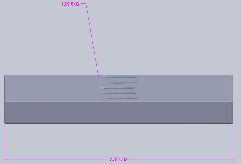
26 3) Make a large enough noose, at the other end of the fishing string, so that the dial torque wrench s handle fits inside the noose. 4) Hang the weight to a known distance. 5) Measure the reading off the dial torque wrench and compare to theoretical value. The results from calibrating the torque wrenches are listed in Table 15. The procedure for calibration was performed at the beginning and at intermittent times throughout testing. Every time the calibration procedure was performed the same measured values occurred. Table 15 Calibration verification of torque wrenches. Calibration Verification Torque Wrench Calculated Value Measured Value 0-75 in-lbs. Torque Wrench 5.45 in-lbs. 5.5 in-lbs in-lbs. Torque Wrench 5.45 in-lbs. 5 in-lbs Fixtures Unseated State Fixture No fixtures were manufactured for the unseated state tests. A 6 inch Craftsman table vise is used to clamp the test specimens for the unseated state Seated State Fixtures For the seated state tests, fixtures were made so that multiple test specimens can be preloaded at once. The fixtures are made out of 304 stainless steel because of its ability to resist corrosion. Figures 2-4 illustrate all dimensions and tolerances for the fixtures. The test fixtures through holes are oversized to eliminate contact between the fasteners and the through holes, which can affect the torque measurements. 14


27 Figure 2 Top view for seated state fixtures. Figure 3 Front view of seated state fixtures. Figure 4 Side view of seated state fixtures. 15
28 2.3 Preparing the Test Specimen Inspection Process Before any anaerobic adhesive is applied to the threaded fastener the tolerances are inspected to ensure consistency between threaded fasteners. Any threaded fastener that was not within tolerance was not used for the experiment. This was determined by assembling the cap screw and hex nut. If during the assembly the hex nut is not freely mating with cap screw the combination is considered to be out of tolerance due to thread size being undersized or burrs on the threads. Another issue that can occur is having the thread size oversized. This is determined by mating a cap screw with a hex nut and applying a moment perpendicular to the direction of the threads. If the hex nut moves a significant amount, compared to the average amount, the threads are considered to be oversized. After the threaded fasteners have been inspected the next step is to clean the cap screws and hex nuts Cleaning Process All cap screw, hex nuts, flat washers, and fixtures are cleaned to remove contaminates and lubricants. This ensures consistency between test specimens. The cleaning process differs between the unseated and seated state Cleaning Process for Unseated State Tests 1) Place the cap screws and hex nuts in the ultrasonic cleaner containing MEK. 2) Turn on the ultrasonic cleaner 3) After 5 minutes turn off the ultrasonic cleaner 4) Remove the cap screws and hex nuts using tongs 5) Place the cap screws and hex nuts on a lint free paper towel or cloth. 6) Leave the test specimens to air dry for 5 minutes. 16
29 Cleaning Process for Seated State Tests Cleaning Process of Fixture for Seated State 1) Place the fixtures in the ultrasonic cleaner containing MEK. 2) Turn on the ultrasonic cleaner. 3) After 5 minutes turn off the ultrasonic cleaner. 4) Remove fixtures using tongs. Be sure to firmly hold the fixture to prevent the MEK from splashing out of the ultrasonic cleaner. 5) Place fixtures on a lint free paper towel or cloth. 6) Leave the fixtures to air dry for 5 minutes. 7) If the fixtures contain remnants from the cured anaerobic adhesive, lap the fixtures using a 120 grit Emory cloth or higher until, contaminates (e.g., cured Loctite) are removed. 8) Repeat steps 1 thru 6 to remove debris introduced after lapping Cleaning Process of Threaded Fasteners for Seated State 1) Place the cap screw, hex nuts, and flat washers in the ultrasonic cleaner containing MEK. 2) Turn on the ultrasonic cleaner. 3) After 5 minutes turn off the ultrasonic cleaner. 4) Remove the cap screw, hex nuts, and flat washers using tongs. 5) Place the cap screw, hex nuts, and flat washers on a lint free paper towel or cloth. 6) Leave the test specimens to air dry for 5 minutes. 2.4 Unseated State Test Procedure After all the threaded fasteners that are going to be tested have been inspected and cleaned, the following step is to apply the adhesive to the cap screw and hex nut. Assemble the cap screw and hex nut containing adhesive and let threaded fastener cure for a sufficient amount 17
30 of time. Once the curing time has been reached, testing of the threaded fastener is achieved by holding the head of the cap screw on a bench vise. A torque wrench is used to record prevailing torque data from the fastener Initial Unseated State Preparation of Test Specimens for Initial Unseated State 1) Apply anaerobic adhesive to the cap screw until the threads are filled. Apply from the start of the threads to about a ¼ of inch up the thread. Two drops of adhesive is usually sufficient to fill the threads. 2) Apply anaerobic adhesive to the hex nut until the gaps between the threads are filled. One drop of anaerobic adhesive is sufficient to fill the threads. 3) Assemble the cap screw and hex nut that contains anaerobic adhesive until three full threads are exposed. Be sure adhesive is visible where the hex nut is placed to cure. 4) Let the assembly cure for 48 hours on a lint free paper towel or cloth without any interruptions. 5) After the curing time has been reached lightly wipe any excess adhesive from the threads of the cap screw with a lint free paper towel or cloth. Be sure to not disrupt the hex nuts position or contaminate the threaded fastener Test Procedure for Initial Unseated State 1) Clamp the threaded fastener using a table vise as shown in Figure 5. Clamp the head of the cap screw so that the torque wrench can be applied to the hex nut. 18
 Apply a torque in the counter-clockwise direction, to the nut, gradually until motion is initiated. Record the breakaway torque at the instant of motion without stopping rotation.")
31 Figure 5 Threaded fastener clamped on table vise. 2) Use a 0-75 in-lb. dial type torque wrench with 7/16 socket. 3) Apply a torque in the counter-clockwise direction, to the nut, gradually until motion is initiated. Record the breakaway torque at the instant of motion without stopping rotation. 4) Keep applying the torque gradually and continuously while recording the torques at 2-5, 90,180, 270, and 360 degrees relative to the position where the torque was first applied. If necessary one can stop to record the data but when the torque is re-applied be sure to rotate at the same rate Reuse of the Unseated State Once the initial unseated testing has been performed the next step is to prepare the test specimen for reuse in the unseated state. This is done simply by removing the hex nut completely from the cap screw and then reassembling the hex nut to the same location where it was cured at for the initial unseated state Preparation of Test Specimens for Reuse of the Unseated State 1) Remove the hex nut completely from the cap screw. 2) Place the hex nut exactly the same manner it was removed onto the threads of the cap screw. 19
32 3) Fasten the hex nut to the location where it was fastened too in the initial unseated state. It should be fastened until approximately three full threads are exposed from the hex nut. 4) Let the assembly cure for 48 hours on a lint free paper towel or cloth without any interruptions Test Procedure for Reuse of the Unseated State 1) Clamp the threaded fastener using a table vise as shown in Figure 1. Clamp the head of the cap screw so that the torque wrench can be applied to the hex nut. 2) Use a 0-75 in-lb. dial type torque wrench with 7/16 socket. 3) Apply a torque in the counter-clockwise direction, to the nut, gradually until motion is initiated. Record the breakaway torque at the instant of motion without stopping rotation. 4) Keep applying the torque gradually and continuously while recording the torques at 2-5, 90,180, 270, and 360 degrees relative to the position where the torque was first applied. If necessary one can stop to record the data but when the torque is re-applied be sure to rotate at the same rate Reuse of the Unseated State Adding Anaerobic Adhesive The preparation of the reuse with adding anaerobic adhesive for the unseated state is similar to that of the reuse for the unseated state. The only difference is when the hex nut is completely removed, anaerobic adhesive is added to the hex nut and cap screw. Once the adhesive has been added, the hex nut is placed in the same location where it previously was cured at. 20
33 Preparation of Test Specimens for Reuse of Unseated State Adding Anaerobic Adhesive 1) Remove the hex nut completely from the cap screw. 2) Add 2 drop of anaerobic adhesive to the cap screw. Apply from the start of the threads to about a ¼ inch up the thread. 3) Add 1 drop of anaerobic adhesive to the hex nut. 4) Place the hex nut exactly the same manner it was removed onto the threads of the cap screw. 5) Fasten the hex nut to the location where it was previously cured at. It should be fastened until approximately three full threads are exposed from the hex nut. 6) Let the assembly cure for 48 hours on a lint free paper towel or cloth without any interruptions Test Procedure for Reuse of Unseated State Adding Anaerobic Adhesive 1) Clamp the threaded fastener using a table vise as shown in Figure 1. Clamp the head of the cap screw so that the torque wrench can be applied to the hex nut. 2) Use a 0-75 in-lb. dial type torque wrench with 7/16 socket. 3) Apply a torque in the counter-clockwise direction, to the nut, gradually until motion is initiated. Record the breakaway torque at the instant of motion without stopping rotation. 4) Keep applying the torque gradually and continuously while recording the torques at 2-5, 90,180, 270, and 360 degrees relative to the position where the torque was first applied. If necessary one can stop to record the data but when the torque is re-applied be sure to rotate at the same rate. 21
34 2.5 Seated State Procedure Once the test specimens and fixtures have been inspected and cleaned, the following step is to apply molybdenum disulfide (MoS 2 ) to both sides of the flat washers. The reason for applying MoS 2 is to prevent galling from occurring. After the flat washers are placed under the head of the cap screws and the partial assembly is inserted into the fixtures. At the other end of the fixture, where the threads are exposed, insert the flat washers coated with MoS 2. Now anaerobic adhesive is applied to the threads of the caps screws and hex nuts and fastened to a designated preload. Once it is sufficiently cured, testing of the threaded fastener is achieved by holding the head of the cap screw on a table vise and using a torque wrench to record prevailing torque data Initial Seated State Preparation of Test Specimens for Initial Seated State 1) Place the flat washers at a location where it is safe to apply MoS 2. 2) Spray MoS 2 to the surface of the flat washer until the entire surface is coated. Spray from about 16 inches away from the surface. 3) Let the MoS 2 dry until it has a dark opaque finish. The drying process can be accelerated using a heat gun from approximately two feet away until the same dark opaque finish occurs. 4) Once dried flip the flat washer to the surface not containing MoS 2. 5) Spray MoS2 to the surface of the flat washer until the entire surface is coated. Spray from about 16 inches away from the surface. 22
 Grip the fixture using a table vise so that the bolt holes are parallel to the ground as shown in Figure 6. Figure 6 Seated state fixture fastener install.")
35 6) Let the MoS2 dry until it has a dark opaque finish. The drying process can be accelerated using a heat gun from approximately two feet away until the same dark opaque finish occurs. 7) Grip the fixture using a table vise so that the bolt holes are parallel to the ground as shown in Figure 6. Figure 6 Seated state fixture fastener install. 8) Place a flat washer containing MoS 2 on a cap screw. 9) Insert the cap screw and flat washer with MoS 2 into the fixture. 10) Insert a flat washer containing MoS 2 on the other side of the fixture where the cap screw threads are exposed. 11) Apply anaerobic adhesive to the cap screw until the threads are filled. Apply from the start of the threads until of an inch before the fixture. Two or three drops of adhesive is usually sufficient to fill the threads. 12) Apply anaerobic adhesive to the hex nut until the gaps between the threads are filled. One drop of anaerobic adhesive is sufficient to fill the threads. 23
 Unload the fixture, containing the test specimens, from the table vise.")
36 13) Assemble the hex nut to the cap screw until hand tight. Be sure that the cap screw is centered to the hole on the fixture. If multiple test specimens can be loaded to the same fixture, repeat steps 8-13 until fixture is completely loaded. 14) Unload the fixture, containing the test specimens, from the table vise. 15) Clamp the head of the cap screw using the table vise as shown in Figure 7. Figure 7 Clamping the head of the cap screw with a table vise. 16) Using a dial torque wrench rated for in-lbs. with a 7/16 socket, preload the threaded fastener until 150 in-lbs. which corresponds to a preload of about 3636 lbs. Once you reach specified torque, hold at the specified torque for five seconds. 17) Relieve the hex nut from the torque. Re-apply and hold to the specified torque for an additional 10 seconds. (Note: The hex nut usually turns during the first couple of seconds of the reapplication of the torque.) 18) For multiple test specimens on one fixture repeat steps ) Once the threaded fastener is preloaded let the assemblies cure for 48 hours without disturbances. 20) After the curing time has been reached lightly wipe any excess adhesive from the threads of the cap screw with a lint free paper towel or cloth. Be sure to not disrupt the hex nuts position or contaminate the threaded fastener. 24
37 Test Procedure for Initial Seated State 1) Clamp the head of the cap screw using a table vise as shown in Figure 7. 2) Use a dial torque wrench rated for in-lbs. with 7/16 socket. 3) Apply a torque in the counter-clockwise direction, to the nut, gradually until motion is initiated. Record the breakaway torque at the instant of motion without stopping rotation. 4) Keep applying the torque gradually and continuously and while recording the torque at 2-5 degrees. Once the removal torque is less than 75 in-lbs., switch to the dial torque wrench rated for 0-75 in-lbs. for accurate readings. This should occur at approximately 60 degrees. 5) Using the dial torque wrench rated for 0-75 in-lbs., apply the torque gradually and continuously while recording the torques at 90,180, 270, and 360 degrees relative to the position where the torque was first applied. If necessary one can stop to record the data but when the torque is re-applied be sure to rotate at the same rate Re-Use of the Seated State Once the initial seated testing has occurred, the step that follows is to prepare the test specimen for the re-use in the seated state. The first step is to remove the hex nut completely from the cap screw. Then reassemble the hex nut to the cap screw and preload to the designated torque Preparation of Test Specimens for Re-Use of the Seated State 1) Clamp the head of the cap screw using the table vise as shown in Figure 7. 2) Remove the hex nut completely from the cap screw. 3) Assemble the hex nut to the cap screw until hand tight. Be sure that the cap screw is centered to the hole on the fixture. 25
38 4) Using a dial torque wrench rated for in-lbs. with a 7/16 socket, preload the threaded fastener until 150 in-lbs. which corresponds to a preload of about 3636 lbs. Once you reach specified torque, hold at the specified torque for five seconds. 5) Relieve the hex nut from the torque. Re-apply and hold to the specified torque for an additional 10 seconds. 6) For multiple specimens on one fixture repeat steps ) Once the threaded fastener is preloaded let the assemblies cure for 48 hours without disturbances Test Procedure for Re-Use of the Seated State 1) Clamp the head of the cap screw using a table vise as shown in Figure 7. 2) Use a dial torque wrench rated for in-lbs. with 7/16 socket. 3) Apply a torque in the counter-clockwise direction, to the nut, gradually until motion is initiated. Record the breakaway torque at the instant of motion without stopping rotation. 4) Keep applying the torque gradually and continuously and while recording the torque at 2-5 degrees. Once the removal torque is less than 75 in-lbs., switch to the dial torque wrench rated for 0-75 in-lbs. for accurate readings. This should occur at approximately 60 degrees. 5) Using the dial torque wrench rated for 0-75 in-lb., apply the torque gradually and continuously while recording the torques at 90,180, 270, and 360 degrees relative to the position where the torque was first applied. If necessary one can stop to record the data but when the torque is re-applied be sure to rotate at the same rate. 26
39 2.5.3 Reuse of the Seated State Adding Anaerobic Adhesive The preparation of the reuse with adding anaerobic adhesive for the seated state is similar to that of the reuse of the seated state. The only difference is when the hex nut is completely removed; anaerobic adhesive is added to the hex nut and cap screw. Then the cap screw and hex nut are reassembled and preloaded to the designated amount Preparation of Test Specimens for Reuse of the Seated State Adding Anaerobic Adhesive 1) Clamp the head of the cap screw using the table vise as shown in Figure 7. 2) Remove the hex nut completely from the cap screw. 3) Apply anaerobic adhesive to the cap screw until the threads are filled. Apply from the start of the threads until of inches before the fixture. Two drops of adhesive is usually sufficient to fill the threads. 4) Apply anaerobic adhesive to the hex nut until the gaps between the threads are filled. One drop of anaerobic adhesive is sufficient to fill the threads. 5) Assemble the hex nut to the cap screw until hand tight. Be sure that the cap screw is centered to the hole on the fixture. 6) Using a dial torque wrench rated for in-lbs. with a 7/16 socket, preload the threaded fastener until 150 in-lbs. which corresponds to a preload of about 3636 lbs. Once you reach specified torque, hold at the specified torque for five seconds. 7) Relieve the hex nut from the torque. Re-apply and hold to the specified torque for an additional 10 seconds. 8) For multiple specimens on one fixture repeat steps
40 9) Once the threaded fastener is preloaded let the assemblies cure for 48 hours without disturbances Test Procedure for Reuse of the Seated State Adding Anaerobic Adhesive 1) Clamp the head of the cap screw using a table vise as shown in Figure 7. 2) Use a dial torque wrench rated for in-lb. with 7/16 socket. 3) Apply a torque in the counter-clockwise direction, to the nut, gradually until motion is initiated. Record the breakaway torque at the instant of motion without stopping rotation. 4) Keep applying the torque gradually and continuously and while recording the torque at 2-5 degrees. Once the removal torque is less than 75 in-lbs., switch to the dial torque wrench rated for 0-75 in-lbs. for accurate readings. This should occur at approximately 60 degrees. 5) Using the dial torque wrench rated for 0-75 in-lbs., apply the torque gradually and continuously while recording the torques at 90,180, 270, and 360 degrees relative to the position where the torque was first applied. If necessary one can stop to record the data but when the torque is re-applied be sure to rotate at the same rate. 2.6 Test Matrix Combinations of three fastener materials/coatings and three anaerobic adhesives were tested. Preliminary tests with 5 specimens of plain grade 8 and 5 specimens of yellow-zinc grade 8 showed typical removal torque variation of about 5 through 7 in-lbs. for a given removal angle. Since the prevailing torque locking feature specification range is 3.5 through 30 in-lbs., a sample size of 5 specimens was determined to be reasonable. All test configurations have at least 5 specimens but most test configurations contain specimens were tested each that 28
41 underwent cure times of 48 hours for the initial use, reuse without adding anaerobic adhesive, and reuse applying additional anaerobic adhesive to the threads. Table 16 Test matrix. Test Number Fastener Type Test Type Adhesive Type 1 Plain grade 8 Unseated Loctite Plain grade 8 Unseated Loctite Plain grade 8 Unseated Loctite Plain grade 8 Unseated Loctite Plain grade 8 Unseated Loctite Yellow-zinc grade 8 Unseated Loctite Yellow-zinc grade 8 Unseated Loctite Yellow-zinc grade 8 Unseated Loctite Yellow-zinc grade 8 Unseated Loctite Yellow-zinc grade 8 Unseated Loctite Plain grade 8 Unseated Loctite 222MS 12 Plain grade 8 Unseated Loctite 222MS 13 Plain grade 8 Unseated Loctite 222MS 14 Plain grade 8 Unseated Loctite 222MS 15 Plain grade 8 Unseated Loctite 222MS 16 Yellow-zinc grade 8 Unseated Loctite 222MS 17 Yellow-zinc grade 8 Unseated Loctite 222MS 18 Yellow-zinc grade 8 Unseated Loctite 222MS 19 Yellow-zinc grade 8 Unseated Loctite 222MS 20 Yellow-zinc grade 8 Unseated Loctite 222MS 21 A-286 Unseated Loctite 222MS 22 A-286 Unseated Loctite A-286 Unseated Loctite A-286 Unseated Loctite Plain grade 8 Unseated Loctite Plain grade 8 Unseated Loctite Plain grade 8 Unseated Loctite Plain grade 8 Unseated Loctite Plain grade 8 Unseated Loctite Yellow-zinc grade 8 Unseated Loctite Yellow-zinc grade 8 Unseated Loctite Yellow-zinc grade 8 Unseated Loctite Yellow-zinc grade 8 Unseated Loctite Yellow-zinc grade 8 Unseated Loctite Plain grade 8 Unseated Loctite Plain grade 8 Unseated Loctite Plain grade 8 Unseated Loctite Plain grade 8 Unseated Loctite
42 Table 16 (Continued) Test Number Fastener Type Test Type Adhesive Type 39 Plain grade 8 Unseated Loctite Yellow-zinc grade 8 Unseated Loctite Yellow-zinc grade 8 Unseated Loctite Yellow-zinc grade 8 Unseated Loctite Yellow-zinc grade 8 Unseated Loctite Yellow-zinc grade 8 Unseated Loctite A-286 Unseated Loctite 222MS 46 A-286 Unseated Loctite A-286 Unseated Loctite Plain grade 8 Unseated Loctite 222MS 49 Plain grade 8 Unseated Loctite 222MS 50 Plain grade 8 Unseated Loctite 222MS 51 Plain grade 8 Unseated Loctite 222MS 52 Plain grade 8 Unseated Loctite 222MS 53 Plain grade 8 Unseated Loctite Plain grade 8 Unseated Loctite Plain grade 8 Unseated Loctite Plain grade 8 Unseated Loctite Plain grade 8 Unseated Loctite Plain grade 8 Unseated Loctite Plain grade 8 Unseated Loctite Plain grade 8 Unseated Loctite Plain grade 8 Unseated Loctite Plain grade 8 Unseated Loctite Yellow-zinc grade 8 Unseated Loctite 222MS 64 Yellow-zinc grade 8 Unseated Loctite 222MS 65 Yellow-zinc grade 8 Unseated Loctite 222MS 66 Yellow-zinc grade 8 Unseated Loctite 222MS 67 Yellow-zinc grade 8 Unseated Loctite 222MS 68 Yellow-zinc grade 8 Unseated Loctite Yellow-zinc grade 8 Unseated Loctite Yellow-zinc grade 8 Unseated Loctite Yellow-zinc grade 8 Unseated Loctite Yellow-zinc grade 8 Unseated Loctite Yellow-zinc grade 8 Unseated Loctite Yellow-zinc grade 8 Unseated Loctite Yellow-zinc grade 8 Unseated Loctite Yellow-zinc grade 8 Unseated Loctite Yellow-zinc grade 8 Unseated Loctite Plain grade 8 Seated Loctite Plain grade 8 Seated Loctite Plain grade 8 Seated Loctite
Threadlocking Adhesives
 Threadlocking Adhesives Locking of Threaded Fasteners Why use a Threadlocker? threadlocking products prevent self-loosening and secure any threaded fastener against vibration and shock loads. They are
9/8/98 AC B CAUTION THE FOLLOWING TORQUE VALUES ARE DERIVED FROM OIL FREE CADMIUM PLATED THREADS.
 TABLE 7-1. Recommended torque values (inch-pounds). CAUTION THE FOLLOWING TORQUE VALUES ARE DERIVED FROM OIL FREE CADMIUM PLATED THREADS. TORQUE LIMITS RECOMMENDED FOR INSTAL- LATION (BOLTS LOADED PRIMARILY
What is a fastener? A device to locate or hold parts
 What is a fastener? A device to locate or hold parts As a repair technician you will become skilled at removing, reconditioning, replacing, and installing fasteners. An important skill to learn is how
What is a fastener? A device to locate or hold parts
 What is a fastener? A device to locate or hold parts As a repair technician you will become skilled at removing, reconditioning, replacing, and installing fasteners. An important skill to learn is how
25000 Series Lo-T TM Butterfly Control Valve Instructions
 November 2001 25000 Series Lo-T TM Butterfly Control Valve Instructions Instruction No. 25.1:IM PRELIMINARY STEPS Before installation, note the flow direction arrow on the valve body. The flow should enter
AFB (AIR FAN BEARING) INSTALLATION GUIDE
 INSTALLATION GUIDE") 654 AFB (AIR FAN BEARING) INSTALLATION GUIDE AFB PARTS Bearing Housing - Secured together with two 3/8 x 1.25 in. Cap Screws Black Wiper Seals - Secured together with O-ring cord (Subsequently depicted
654 AFB (AIR FAN BEARING) INSTALLATION GUIDE AFB PARTS Bearing Housing - Secured together with two 3/8 x 1.25 in. Cap Screws Black Wiper Seals - Secured together with O-ring cord (Subsequently depicted
Page 1. SureMotion Quick-Start Guide: LACPACC_QS 1st Edition - Revision A 03/15/16
 R K C T I Repair Kit Product Compatibility Repair Kit # Linear Actuator Assembly # LACPACC-002 LACPACC-003 LACP-16TxxLP5 (0.5-in lead screw pitch) LACP-16TxxL1 (1-in lead screw pitch) C P I R K 4 ea Flanged
HARDLOCK NUT RIM & HARDLOCK NUT BASIC
 1 Clamp Load [kn] FEATURES OF HARDLOCK NUT Reusable without reduction in performance! Full torque management and completely fastened even with ZERO (0) clamp load! Available in various materials and surface
NAVSEA STANDARD ITEM
 NAVSEA STANDARD ITEM FY-19 DATE: 01 OCT 2017 CATEGORY: I 1. SCOPE: 1.1 Title: Threaded Fastener Requirements; accomplish 2. REFERENCES: 2.1 Standard Items 2.2 S9086-CJ-STM-010/075, Fasteners 3. REQUIREMENTS:
AN, MS, NAS Bolts. AN3 20 bolts are identified by a multi-part code:
 AN, MS, NAS Bolts Most bolts used in aircraft structures are either (a) general-purpose, (b) internal-wrenching or (c) close-tolerance AN, NAS, or MS bolts. Design specifications are available in MIL-HDBK-5,
SECTION 3. BOLTS. bolt is a standard AN-type or a special-purpose bolt, and sometimes include the manufacturer.
 9/8/98 AC 43.13-1B SECTION 3. BOLTS 7-34. GENERAL. Hardware is the term used to describe the various types of fasteners and small items used to assemble and repair aircraft structures and components. Only
USER MANUAL Nord-Lock X-series washers
 USER MANUAL Nord-Lock X-series washers JOINT GUIDE 3 ASSEMBLY INSTRUCTIONS 4 TECHNICAL DATA 5 TORQUE GUIDE 5 THE EXCEPTIONAL SYSTEM THAT PREVENTS BOLT LOOSENING AND SLACKENING Nord-Lock X-series washers
Reliance SG800 Series Steel Water Gage Valves
 Installation, Operation, & Maintenance Instructions R500.541D1 10/16/2016 Reliance SG800 Series Steel Water Gage Valves Note: Design variations in Steel Water Gage Valves necessitate typical illustrations,
Tube Facing Tool.
 www.swagelok.com Tube Facing Tool This manual contains important information for the safe and effective operation of the Swagelok TF72 series tube facing tool. Users should read and understand its contents
Assembly, Use and Care Instructions
 Assembly, Use and Care Instructions Product #336677 Instruction #1068318 Rev. F Thank you for purchasing a Caldwell Lead Sled DFT 2. The Lead Sled DFT 2 comes to you partially assembled. It will require
LOCTITE WEBINAR SERIES Threadlocking & the Torque-Tension Relationship
 LOCTITE WEBINAR SERIES Threadlocking & the Torque-Tension Relationship Meet Your Presenters Doug Lescarbeau Michael Feeney Market Development Director Doug.Lescarbeau@Henkel.co m Application Engineer Michael.Feeney@Henkel.com
AN, MS, NAS Bolts. AN3 20 bolts are identified by a multi-part code:
 AN, MS, NAS Bolts Most bolts used in aircraft structures are either (a) general-purpose, (b) internal-wrenching or (c) close-tolerance AN, NAS, or MS bolts. Design specifications are available in MIL-HDBK-5,
3 Emergency Breakaway Coupling
 SM64227 July 2008 Applicable addition manuals: N/A Aerospace Group Conveyance Systems Division Carter Ground Fueling Maintenance & Repair Manual 3 Emergency Breakaway Coupling Model 64227 Table of Contents
The DeltaGrip System. Safety and Operating Instructions. Trigger. Air Supply Connection. Handle Assembly. Air Line Assembly.
 The DeltaGrip System Safety and Operating Instructions Trigger Air Supply Connection Handle Assembly Air Line Assembly Punch Die Pneumatic Diaphragm Assembly Shackle, Pin & Jam Nut Jaw Frame Shoulder Screw
Rayport G Eco Dealer Kit
 Rayport G Eco Dealer Kit Installation Guide www.aetenergy.com Supporting a Cleaner, Greener Tomorrow 1. Table of Contents 1. Table of Contents P2 2. Installer Notes P3 3. Parts List P4-7 4. Tool List P8
Fasteners. Bolts. NAPA FastTrack Counter Sales Training Fasteners Page 1. Figure 1. Typical Measurements for a Bolt or Hex Head Cap Screw
 Fasteners Many types and sizes of fasteners are used in the automotive industry. Each fastener is designed for a specific purpose and condition. One of the most commonly used type of fastener is the threaded
Fluid Sealing Association
 Fluid Sealing Association STANDARD FSA-MG-501-02 STANDARD TEST METHOD FOR INWARD BUCKLING OF SPIRAL-WOUND GASKETS 994 Old Eagle School Road, Suite 1019 Wayne, Pennsylvania 19087-1866 Phone: (610) 971-4850
HDL(M)6 Nut/Screw Assembly
6 Nut/Screw Assembly") HDL(M)6 Nut/Screw Assembly Remove, repair, and reassemble the nut and screw assembly in your HDL series double lock vise. In these instructions when we refer to the front of the vise or nut/screw assembly,
HDL(M)6 Nut/Screw Assembly Remove, repair, and reassemble the nut and screw assembly in your HDL series double lock vise. In these instructions when we refer to the front of the vise or nut/screw assembly,
Type XTSR71 Sizes
 (Page 1 of 13) s 494-5258 Type XTSR71 s 494-5258 Figure 1 Thomas XTSR71 Coupling 1. General Information 1.1 Thomas Couplings are designed to provide a mechanical connection between the rotating shafts
installation guide 1 GUIDE#: pwb-assault-001
 assault WAKEBOARD tower installation guide INSTALLATION SUPPORT 1 important information This Aerial wakeboard tower fits motor boats with 76-108 inch wide beam widths. This measurement is taken from the
JK TrailGate JK TrailGate
 INSTALLATION INSTRUCTIONS INST-17-66-010_A JK TrailGate IMPORTANT: Thank you for purchasing this Poison Spyder product. Please read through this entire document before proceeding with installation. If
No November, Char-Lynn. Hydraulic Motor. Repair Information. R Series General Purpose Geroler Motor
 Char-Lynn Hydraulic Motor No. 7-142 November, 1996 Repair Information General Purpose Geroler Motor 001 002 2 Geroler Motors Parts Drawing Bearing Race Needle Thrust Bearing Key Output Shaft Cap Screw
Reliance SG777 Series Steel Water Gage Valves
 Installation, Operation, & Maintenance Instructions R500.SG777 10/16/2016 Reliance SG777 Series Steel Water Gage Valves Note: Design variations in Steel Water Gage Valves necessitate typical illustrations,
Structural Bolting. Notice the Grade 5 has a much smaller head configuration and a shorter shank then the grade A325 structural bolt.
 Structural Bolting ASTM F3125/F3125M is a structural bolt specification covering inch and metric bolt grades. This specification contains 4 inch series bolting grades: A325, F1852, A490, and F2280. These
Evaluation of In-Pavement Light Fixture Designs and Performance
 Evaluation of In-Pavement Light Fixture Designs and Performance Presented to: IES ALC Fall Technology Meeting By: Joseph Breen Date: Background In-Pavement Light Fixture Assemblies Utilize a Circle of
Fasteners. Metal Fasteners, Joining, and Adhesives. Bolts. Metal Fasteners, Joining, and Adhesives
 Metal Fasteners, Joining, and Adhesives Fasteners Metal assemblies are often held together with fasteners, hardware devices that mechanically join or affix two or more objects together. Assembling with
Fisher 667 Diaphragm Actuator Sizes 30/30i 76/76i and 87
 Instruction Manual 667 Actuator (Size 30/30i - 76/76i and 87) Fisher 667 Diaphragm Actuator Sizes 30/30i 76/76i and 87 Contents Introduction... 1 Scope of Manual... 1 Description... 2 Specifications...
Char-Lynn Hydraulic Motor. Repair Information. R Series General Purpose Geroler Motor November, 1996
 Char-Lynn Hydraulic Motor November, 1996 Repair Information General Purpose Geroler Motor 001 002 2 Geroler Motors Parts Drawing Bearing Race Needle Thrust Bearing Key Output Shaft Cap Screw -001 12 pt
DO35 MAINTENANCE INSTRUCTIONS
 CUSTOMER INFORMATION SHEET NO. 038 DO35 MAINTENANCE INSTRUCTIONS (DO35 V3 LAUNCHED PRODUCTION JUNE 2017) Table of Contents 1.0 Replacing Spindle Bushes V3... 22 2.0 Replacing Locking Mechanism V3... 6
Table of Contents. B. Base Tool Changer...2 MC-6 Manual Tool Changer...2
 Table of Contents B. Base Tool Changer...2 MC-6 Manual Tool Changer...2 1. Product Overview... 2 1.1 Master Plate Assembly... 2 1.2 Tool Plate Assembly... 3 1.3 Optional Modules... 3 2. Installation...
YALE FIGURE 500 & 500R CLOSURE OPERATION AND MAINTENANCE INSTRUCTIONS
 YALE FIGURE 500 & 500R CLOSURE OPERATION AND MAINTENANCE INSTRUCTIONS IMPORTANT INFORMATION Note To Supervisor: Please share this information with your employees and make sure they have received training
Tightening of Structural Joints
 The design, fabrication, assembly and inspection of steel structures using metric high strength structural bolts and nuts to AS 1252 are covered in AS 4100 - SAA Steel Structures Code which should be referred
installation guide 1 GUIDE#: pwb-assault-004
 assault WAKEBOARD tower installation guide INSTALLATION SUPPORT 1 important information This Aerial wakeboard tower fits motor boats with 76-108 inch wide beam widths. This measurement is taken from the
FASTENERS, MEASUREMENTS AND CONVERSIONS
 FASTENERS, MEASUREMENTS AND CONVERSIONS Bolts, Nuts and Other Threaded Retainers Although there are a great variety of fasteners found in the modern car or truck, the most commonly used retainer is the
TECH SHEET PEM - REF / THREAD GALLING. SUBJECT: Root causes and guidelines to promote optimized fastener performance TECH SHEET
 PEM - REF / THREAD GALLING SUBJECT: Root causes and guidelines to promote optimized fastener performance Introduction Occasionally, users of our self-clinching fasteners encounter thread binding issues
General Specification
 General Specification CODE IDENT NO. 23835 SPEC NO. ES504255, REV I ISSUE DATE 2/9/99 SUPERSEDING ES504255 H DATED 6 JANUARY 1999 TORQUE REQUIREMENTS MECHANICAL THREADED FASTENERS (SPACECRAFT STRUCTURE
T Pac2 standard for prevailing torque threadlocker Dri-Loc Plastic. Introduction. Contents. 1 Scope and field of application
 T-26728 Pac2 standard for prevailing torque threadlocker Dri-Loc Plastic Test, material and performance specifications Introduction This standard conforms where applicable to DIN 267 part 28, DIN 267 part
REPAIR INSTRUCTIONS. Cat. No Cat. No MILWAUKEE ELECTRIC TOOL CORPORATION. SDS Max Demolition Hammer. SDS Max Rotary Hammer
 Cat. No. 9-0 SDS Max Demolition Hammer Cat. No. -0 SDS Max Rotary Hammer MILWAUKEE ELECTRIC TOOL CORPORATION W. LISBON ROAD BROOKFIELD, WISCONSIN 00-0 8-9-0 d 000 8-9-0 d Special Tools Require Forcing
FLOOR ANCHOR SYSTEM APPLICATIONS L TRACK APPLICATIONS
 FLOOR ANCHOR SYSTEM APPLICATIONS Sure-Lok recommends the following for floor anchor system layout and installation. These recommendations are not all-inclusive and may not be applicable to every system
1. TOOLS + MATERIALS REQUIRED
 R INSTALLATION INSTRUCTIONS PRODUCT: BALDUR + ODEN CONFIGURATION: BI-PARTING DOOR MOUNT: TOP MOUNT Product is covered by U.S. patents. For more information visit www.krownlab.com. TOOLS + MATERIALS REQUIRED
1/2/2016. Lecture Slides. Screws, Fasteners, and the Design of Nonpermanent Joints. Reasons for Non-permanent Fasteners
 Lecture Slides Screws, Fasteners, and the Design of Nonpermanent Joints Reasons for Non-permanent Fasteners Field assembly Disassembly Maintenance Adjustment 1 Introduction There are two distinct uses
PRODUCT: LOKI INSTALLATION INSTRUCTIONS. Product is covered by U.S. patents. For more information visit
 R INSTALLATION INSTRUCTIONS PRODUCT: LOKI CONFIGURATION: SINGLE DOOR MOUNT: GLASS MOUNT Product is covered by U.S. patents. For more information visit www.krownlab.com . TOOLS + MATERIALS REQUIRED TOOLS
Procedure for Testing Direct Tension Indicators (DTI) Assemblies
 Assemblies") Procedure for Testing Direct Tension Indicators (DTI) Assemblies 1. Scope: This test is to ensure that the bolt will be at or above the specified minimum bolt tension after installation when the direct
Procedure for Testing Direct Tension Indicators (DTI) Assemblies 1. Scope: This test is to ensure that the bolt will be at or above the specified minimum bolt tension after installation when the direct
Disclaimer. Socket Products Socket depth limits maximum torque. Torque figures are based on 80% of maximum torque for a given key size.
 E546 V3 (1/17) Disclaimer Torque values listed in this book are based on mathematical calculations and experimental data. The values are valid only when the matched strength system listed is used. The
Greenslade & Company Rockwell Hardness Tester, Dial Type
 Greenslade & Company Rockwell Hardness Tester, Dial Type Greenslade Hardness Tester Operating Instructions & Parts Manual Please read and save these instructions. Read carefully before attempting to assemble,
STRINGING MACHINE OWNER'S MANUAL. Copyright 1998 GAMMA Sports - All Rights Reserved
 6002 STRINGING MACHINE OWNER'S MANUAL Issue 3 - June 20, 1998 Copyright 1998 GAMMA Sports - All Rights Reserved 6002 OWNER'S MANUAL TABLE OF CONTENTS PAGE 1... WARRANTY PAGE 2... FEATURES PAGE 3... ASSEMBLY
Fasteners. Fastener. Chapter 18
 Fasteners Chapter 18 Material taken from Mott, 2003, Machine Elements in Mechanical Design Fastener A fastener is any device used to connect or join two or more components. The most common are threaded
Rev B C-RING TOOL VA0375 ½ in. OPERATING MANUAL
 Rev B 4-30-0 C-RING TOOL VA0375 ½ in. OPERATING MANUAL Operational Instructions for Vertex C-Ring Tool VA0375 Vertex Fasteners is committed to providing our customers with world-class customer service
BIPPMM03 (Published) Book specs- Dates: / / Lang: ENG01 Applic: PPM
 Book specs- Dates: / / Lang: ENG01 Applic: PPM") BIPPMM03 (Published) Book specs- Dates: 20060412 / 20060412 / 20060412 Lang: ENG01 Applic: PPM Installing the Milnor Diaphragm in the Single Stage Press This document applies to models MP160Axx, MP1604xx,
BIPPMM03 (Published) Book specs- Dates: 20060412 / 20060412 / 20060412 Lang: ENG01 Applic: PPM Installing the Milnor Diaphragm in the Single Stage Press This document applies to models MP160Axx, MP1604xx,
Swivel Hoist Ring RIGGING ACCESSORIES. Color coded to distinguish between UNC (Red) and Metric (Silver) thread types.
 and Metric (Silver) thread types.") RIGGING ACCESSORIES Color coded to distinguish between UNC (Red) and Metric (Silver) thread types. Available in UNC and Metric thread sizes. UNC threads available in sizes from 800 pounds to 100,000 pounds,
RIGGING ACCESSORIES Color coded to distinguish between UNC (Red) and Metric (Silver) thread types. Available in UNC and Metric thread sizes. UNC threads available in sizes from 800 pounds to 100,000 pounds,
Installation Instructions
 Installation Instructions Playworld Systems Model XX1407 Square Picnic Table w/coated Top & Frame Installation Preparation Recommended Crew:...Two (2) adults Installation Time:...1 man-hour Assembly View
DYNATRAC BALL JOINT REBUILD INSTRUCTIONS V5.0
 DYNATRAC PRODUCTS 2007-2018 JEEP JK HEAVY DUTY BALL JOINT JP44-2X3050-C DYNATRAC BALL JOINT REBUILD INSTRUCTIONS V5.0 WARNING: Improper use or installation of this product can cause major failures that
ELECTRIC TOOL CORPORATION
 Cat. No. -0 / Hex Demolition Hammer Cat. No. 0-0 Spline Rotary Hammer MILWAUKEE ELECTRIC TOOL CORPORATION W. LISBON ROAD BROOKFIELD, WISCONSIN 00-0 -9-00 d 000 -9-00 d SpecialTools Require Forcing discs
Threadlocking User s Guide. What You Need to Know to Ensure a Reliable Threaded Assembly
 Threadlocking User s Guide What You Need to Know to Ensure a Reliable Threaded Assembly 1 Threadlocking User s Guide LOCTITE Threadlocking Guide CONTENTS THREADED FASTENERS Functions of a threaded assembly
Installation Instructions
 Installation Instructions XLC Series Self-aligning split bearing Experience In Motion 1 Equipment Check 1.1 Follow plant safety regulations prior to equipment disassembly: Lock out motor. Wear designated
Installation Instructions
 Installation Instructions XLC Generation 2 Self-aligning split bearing Experience In Motion 1 Equipment Check 1.1 Follow plant safety regulations prior to equipment disassembly: Lock out motor. Wear designated
REP Design LLC. 193 Winding Ridge Rd, Southington, CT INSTALLATION INSTRUCTIONS:
 REP Design LLC 193 Winding Ridge Rd, Southington, CT 06489 1-860.426.1894 n7emw@cox.net www.repdesign.us INSTALLATION INSTRUCTIONS: SHD-SO239 Super Heavy Duty SO-239Antenna Mounting System Thank you for
1904, 1904Pg, 1904PgSB, and 1906SB High Capacity Ratchet Knockout Drivers
 INSTRUCTION MANUAL 1904, 1904Pg, 1904PgSB, and 1906SB High Capacity Ratchet Knockout Drivers Read and understand all of the instructions and safety information in this manual before operating or servicing
3. SIGNIFICANCE AND USE 3.1 These test methods provide a quantitative measure of the tack property of a pressure sensitive adhesive.
 Call Letters PSTC-16 Date of Issuance 10/00 Revised 10/03 Revised 05/07 Loop Tack 1. SCOPE 1.1 This test method is intended to determine the tack properties of a pressure sensitive adhesive. This test
3400 E. WALNUT STREET COLMAR, PA DORMAN / ROCKFORD
 WEATHERLY #770 D-2013-A JUNE 2013 SUPERSEDES R-2009-F APR. 2009 2013 DORMAN / ROCKFORD 1-800-523-2492 Corporate Office & Customer Service www.dormanproducts.com 2013 Dorman Products, Inc. No reproduction
PROSTEER BALL JOINT REBUILD INSTRUCTIONS V1.0
 DYNATRAC PRODUCTS 2003-2010 4X4 DODGE 2500/3500 HEAVY DUTY BALL JOINT PROSTEER BALL JOINT REBUILD INSTRUCTIONS V1.0 WARNING: Improper use or installation of this product can cause major failures that could
TAPTITE Fasteners. High Performance Thread Rolling Screws for Metals
 TAPTITE 2000 Fasteners High Performance Thread Rolling Screws for Metals TAPTITE 2000 thread forming technology joins two unique concepts and advances fastener performance to new levels. TAPTITE 2000 fasteners
Tuf-Lite III Fans 3000K Series Hub
 Tuf-Lite III Fans 3000K Series Hub INSTALLATION MANUAL Adjustable Pitch Fan Assembly 11 thru 15 Diameter Hudson Tuf-Lite III fan blades Hudson Tuf-Lite III fan blades are of single piece fiberglass reinforced
Swivel Hoist Ring Page 142
 Swivel Hoist Ring Page 142 Hoist Rings Color coded to distinguish between UNC (Red) and Metric (Silver) thread types HR-125 M HR-125 Available in UNC and Metric thread sizes. UNC threads available in sizes
Contents. Grade 2, 5, 8 Hex Bolts 4. Heavy Hex Head Structural Bolts 6. A325 and A490 Tension Control Bolts (TC) 13. Nuts 22.
 13. Nuts 22.") Who we are Amcan Jumax is the result of a merging between Boulons Jumax and Amcan Threaded Products, two successful companies well established, both with excellent reputations. The new entity is a bigger
Who we are Amcan Jumax is the result of a merging between Boulons Jumax and Amcan Threaded Products, two successful companies well established, both with excellent reputations. The new entity is a bigger
USSC LLC 4 ONE LLC FIELD MODIFICATION INSTRUCTIONS
 1 OF 17 A 1. PURPOSE: Instructions for in field replacement of 9004 mechanical suspension top pan 2. SCOPE: 9004 mechanical suspension with legacy two point LX back frame and current LX back frame 3. PROCEDURE:
MUELLER. Improved, Centurion Series, Modern Improved, and 107. Fire Hydrants. Inserting Extention Sections. Reliable Connections
 insertion Instructions manual MUELLER Improved, Centurion Series, Modern Improved, and 107 table of contents PAGE Centurion Series Fire Hydrant Adding an Extention 2-3 Improved Fire Hydrant Inserting Extention
In normal joints, the clamping force should equal the working load. In gasketed joints, it should be sufficient to create a seal.
 Fastener Quality Act Information Unbrako offers this link to the National Institute of Standards homepage on the Fastener Quality Act as an aide to individuals who need detailed and complete information
AIRCRAFT HARDWARE What You Need To Know By Ron Alexander
 Page 1 of 6 AIRCRAFT CONSTRUCTION An Article Series by Ron Alexander AIRCRAFT HARDWARE What You Need To Know By Ron Alexander The quality of our workmanship in building an airplane is very important. We
Tuf-Lite II Fans 3000H Series Hub
 Tuf-Lite II Fans 3000H Series Hub INSTALLATION MANUAL Adjustable Pitch Fan Assembly 5 through 14 Diameter Hudson Tuf-Lite II Fan Blades Hudson Tuf-Lite II (white, prev. blue**) fan blades are made from
Large Diameter Tapcon
 CONCRETE ANCHORING SPECIALISTS Large Diameter Tapcon (LDT ) Anchors Finished head, Removable Anchor DESCRIPTION/SUGGESTED SPECIFICATIONS Self-threading Anchors SPECIFIED FOR ANCHORAGE INTO CONCRETE The
PRODUCT: BALDUR + ODEN
 R INSTALLATION INSTRUCTIONS PRODUCT: BALDUR + ODEN CONFIGURATION: SINGLE DOOR MOUNT: GLASS MOUNT Product is covered by U.S. patents. For more information visit www.krownlab.com . TOOLS + MATERIALS REQUIRED
CIRRUS AIRPLANE MAINTENANCE MANUAL
 FASTENER AND HARDWARE GENERAL REQUIREMENTS 1. DESCRIPTION This section contains general requirements for common hardware installation. Covered are selection and installation of cotter pins, installation
AR-15 Armorer s Essentials Kit. Product # Instructions # Revision: B
 AR-15 Armorer s Essentials Kit Product #156111 Instructions #1025769 Revision: B 1 INDEX 3 AR-15 Adjustable Receiver Link 3 Pivot Pin and Roll Pin Installation Tool 4 Mag well Vise Block 7 Upper Vise Block
STERILIZATION The following are GUIDELINES for product sterilization.
 The following are GUIDELINES for product sterilization. Rultract retractor assemblies are reusable instruments. They are supplied non-sterile and must be cleaned and sterilized prior to initial use and
MUELLER. Improved, Centurion Series, Modern Improved, and 107. Fire Hydrants. Inserting Extension Sections. Reliable Connections
 insertion Instructions manual MUELLER Improved, Centurion Series, Modern Improved, and 107 table of contents PAGE Centurion Series Fire Hydrant Adding an Extension 2-3 Improved Fire Hydrant Inserting Extension
TAPTITE 2000 Fasteners
 TAPTITE 2000 Fasteners Unique Design Increases Performance TAPTITE 2000 fasteners are designed to provide the benefits of previous TAPTITE fastener products with an innovative new thread design the Radius
LORON SERVICE MANUAL / PARTS LIST SINGLE DOUBLE PALLET HANDLER CONTENTS: PAGE 1 Lift Truck Requirements General Installation Procedures
 LORON SERVICE MANUAL / PARTS LIST SINGLE DOUBLE PALLET HANDLER CONTENTS: PAGE 1 Lift Truck Requirements General Installation Procedures 2 Mounting Options Stop Block Adjustments 3 General Weekly Inspection
Air Cooled Engine Technology. Roth 9 th Ch 3 Fasteners & Sealing Pages 45 65
 Roth 9 th Ch 3 Fasteners & Sealing Pages 45 65 1. Engine & equipment can be common or can be designed to perform specific functions. Fasteners Options Features 2. The of a fastener is actually an inclined
Page 1. SureMotion Quick-Start Guide: LARSACC_QS 1st Edition - Revision A 03/15/16. Standard Steel Bolt/Screw Torque Specifications
 R K C T I Repair Kit Product Compatibility Repair Kit # Linear Actuator Assembly # LARSACC-013 LARSACC-014 LARSD2-08T12BP2C (12-in travel) LARSD2-08T24BP2C (24-in travel) C P I R K 1 ea Ball Screw with
Hydraulic Adapters STEEL PIPE ADAPTERS NPTF DRY SEAL PIPE ASSEMBLY INSTRUCTIONS. Steel Pipe Adapters. Steel Pipe Adapters. Hydraulic.
 CONFORMANCE SAE J54 for hex nipples, expanders, elbows, tees and crosses SAE J54, J50 and J5 for bushing and plugs. Temperature Range -65 0 F to +400 0 F MATERIALS - SAE L4 carbon steel plated zinc with
southpaw enterprises, inc.
 Eye Bolt Wrap 7001 Store these instructions with the enclosed maintenance checklist in a safe place. You may also access them on our website. this in an accessible location: the must be read and familiar
BE1151 Precision Priming Press Instructions
 BE1151 Precision Priming Press Instructions Tech Support: (360) 676-3299 Email: service@bullets.com Web: www.bullets.com Shell Holder Not Included. Introduction The Model BE1151 is designed to be the ultimate
CHEMINSTRUMENTS LABORATORY DRAWDOWN COATER LC-100 OPERATING INSTRUCTION
 CHEMINSTRUMENTS LABORATORY DRAWDOWN COATER LC-100 OPERATING INSTRUCTION PRODUCT DESCRIPTION...2 UNPACKING...3 ASSEMBLY...4 Key Components...4 Set Up...5 OPERATION...5 MAINTANCE...7 WARRANTY...8 1 PRODUCT
Mustang GT350 Caliper Stud Installation Instructions
 2015-2017 Mustang GT350 Caliper Stud Installation Instructions Congratulations on your purchase. The use of these studs will allow for much quicker brake pad changes as the six piston Brembo calipers on
EllisSaw.com. EllisSaw.com P.O. Box Verona, WI
 P.O. Box 9019 Verona, WI 9-019 GENERAL OPERATING & SAFETY INSTRUCTIONS * READ INSTRUCTIONS BEFORE USE * CAUTION: Disconnect power supply cord from power source when doing repair work or changing belt.
TUFTHRED - FRACTIONAL & METRIC SIZES
 3 East Julie Street 800-3-119 (Voice) 90-733-741 (Fax) TUFTHRED - FRACTIONAL & METRIC SIZES No tapping is required; just drill out the damaged threads using fractional or wire gauge drill bits. Then screw
Tuf-Lite II Fans 3000H Series Hub
 Tuf-Lite II Fans 3000H Series Hub INSTALLATION MANUAL Adjustable Pitch Fan Assembly 5 through 14 Diameter Hudson Tuf-Lite II Fan Blades Hudson Tuf-Lite II (white, prev. Blue**) are made from fiberglass
NAVSEA STANDARD ITEM T9074-AS-GIB-010/271, Requirements for Nondestructive Testing Methods
 NAVSEA STANDARD ITEM ITEM NO: 009-48 DATE: 29 JUL 2011 CATEGORY: II 1. SCOPE: 1.1 Title: Pressure Seal Bonnet Valve; repair (shop) 2. REFERENCES: 2.1 S9086-CJ-STM-010/CH-075, Fasteners 2.2. T9074-AS-GIB-010/271,
Table of Contents. GARD Specialists Co., Inc. GARD Specialists Co., Inc. P.O. Box 157 Eagle River, WI Fax
 Table of Contents Heavy Duty Fasteners F-911 Fasteners Introduction... 2 F-911 Fasteners Specifications... 2 F-911 Fasteners Torque Chart... 3 Cap Screws - F-911 Alloy Hex Head, Coarse... 4-9 Assortments,
Repair Instructions ISC. Experience In Motion. ISC1PX Single Pusher Seal
 Repair Instructions ISC ISC1PX Single Pusher Seal Experience In Motion These instructions are written for trained, experienced technicians familiar with the basic principles and tools involved in the installation,
MTS-SP100. RENOGY Pole Mount System E Philadelphia St, Ontario, CA Version: 1.2
 MTS-SP100 RENOGY Pole Mount System 2775 E Philadelphia St, Ontario, CA 91761 1-800-330-8678 1 Version: 1.2 Important Safety Instructions Please save these instructions. This manual contains important safety,
Rhino SD2/XD2 Mini Tote Conversion Kit
 Instruction Sheet P/N 1613210 01 Description See Figure 1. The Rhino SD2/XD2 mini tote conversion kit is used when the material container includes a follower as part of the container structure. The mini
Owner s Manual ODYSSEY BENCH MODEL. O4100B shown REV E. Southern Avenue, Phoenix, AZ USA Workhorseproducts.
 Owner s Manual ODYSSEY BENCH MODEL O4100B shown 67-1375 REV 218 3730 E. Southern Avenue, Phoenix, AZ 85040 USA 800-778-8779 Workhorseproducts.com 1 Table of Contents I. Introduction & Safety Information.
DYNATRAC BALL JOINT REBUILD INSTRUCTIONS V4.0
 DYNATRAC PRODUCTS 2007-2016 4X4 JEEP JK HEAVY DUTY BALL JOINT JP44-2X3050-C DYNATRAC BALL JOINT REBUILD INSTRUCTIONS V4.0 WARNING: Improper use or installation of this product can cause major failures