REQUEST FOR INFORMATION
|
|
|
- Stanley Alban Doyle
- 6 years ago
- Views:
Transcription

1 REQUEST FOR INFORMATION Project: Junction City HS General Contractor: Corp Inc. RFI #: MVCC 0 RFI Title: Cold Framing Submittal EOR Response RFI Section: Date: 0/4/07 Response Required: ASAP Information Requested: In review of the EOR response to our design build submittal we continue to encounter design challenges which steel need to be resolved. I have attached the following containing Items -4 from our engineer (Hayden Engineers) as well as a PDF drawing indentifying the issues and intent. We would request request review and input from the EOR so we can complete the design. Contractor Proposed Options: Designer Answer: Answered By: Date
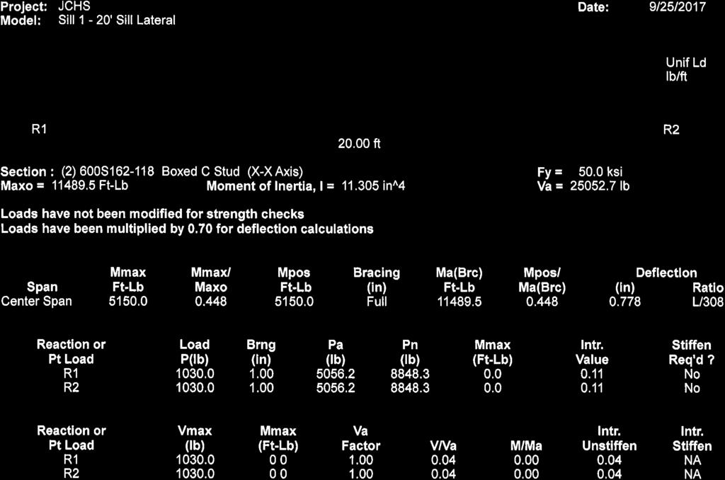
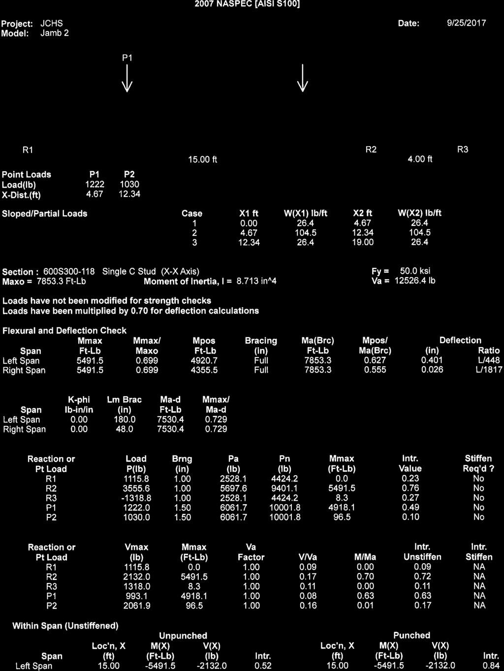
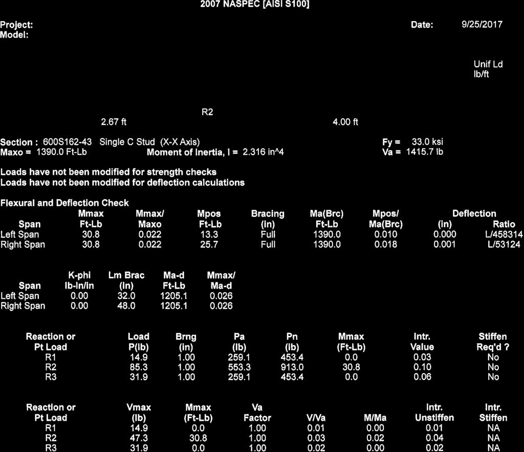
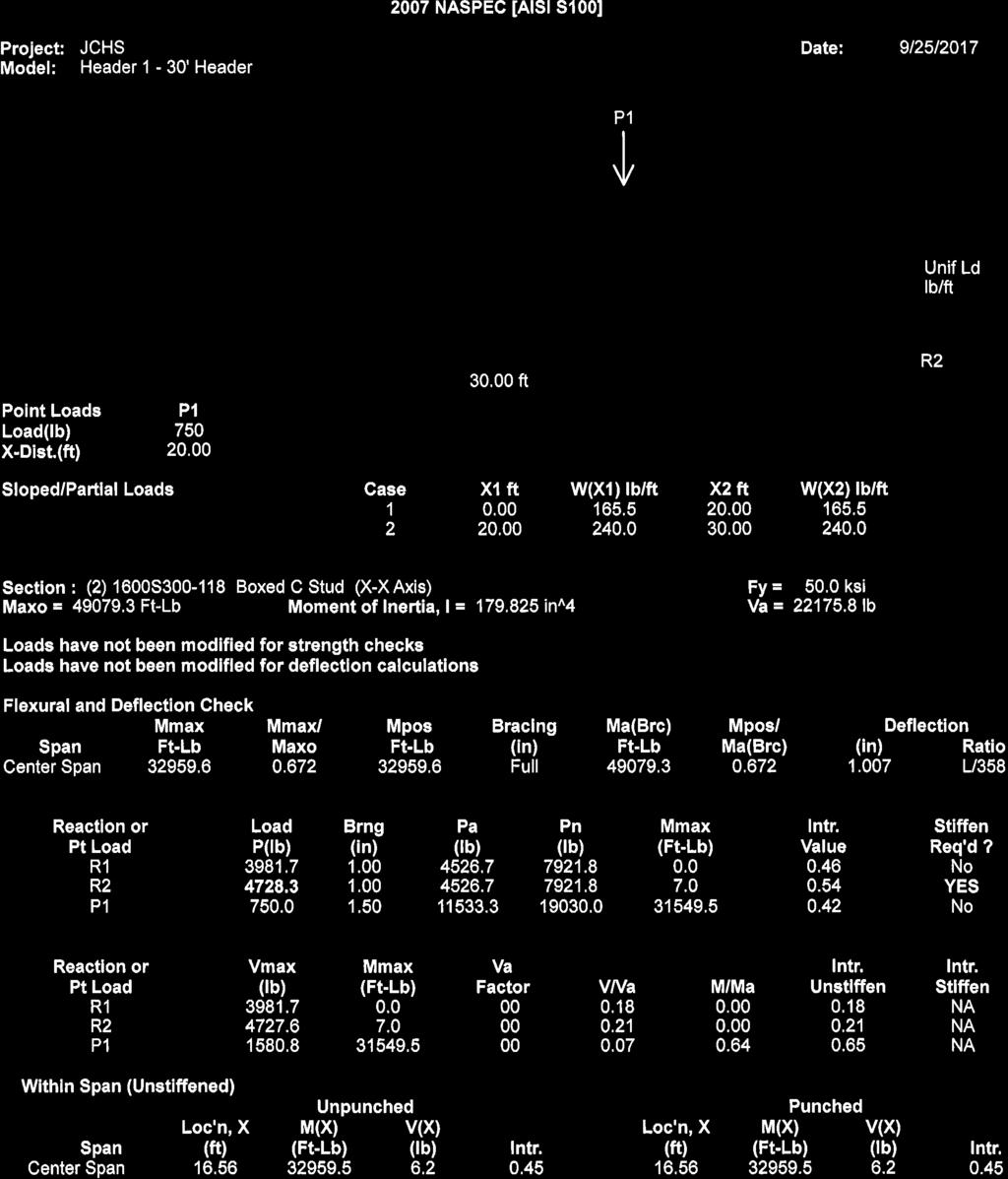
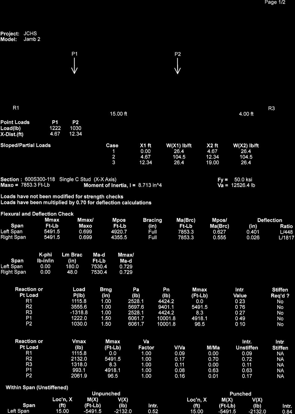
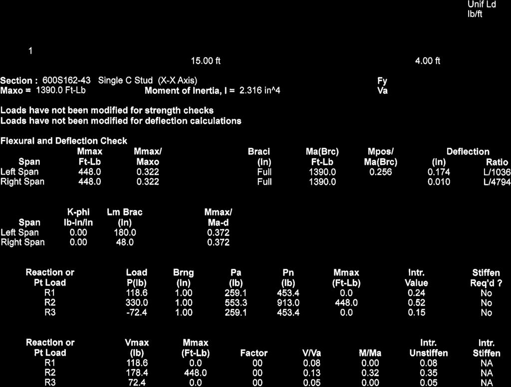
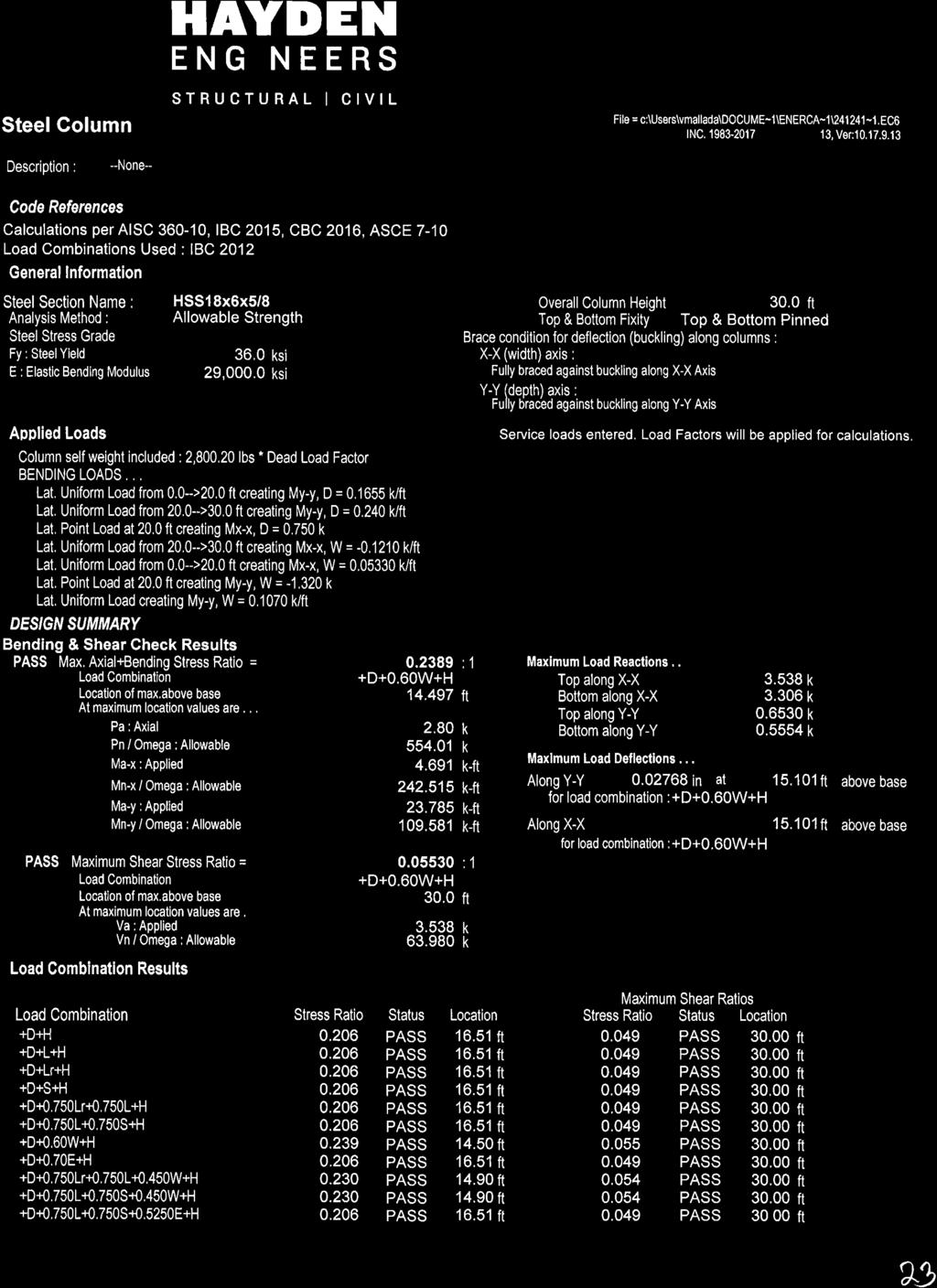
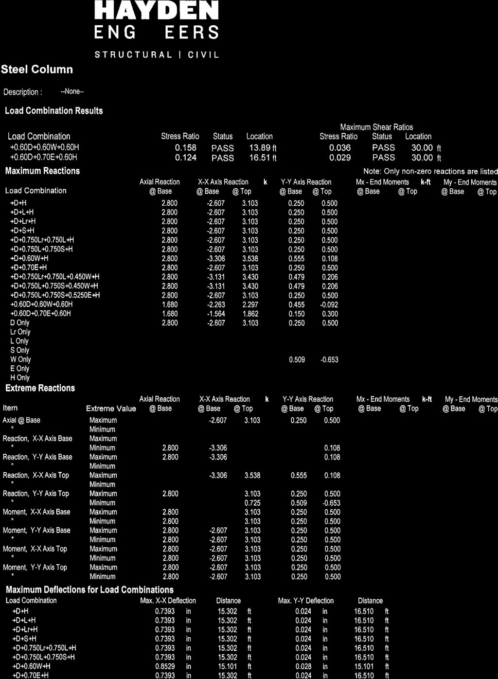
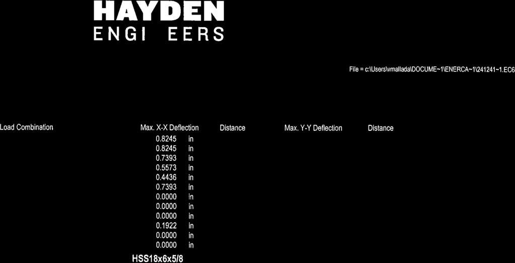
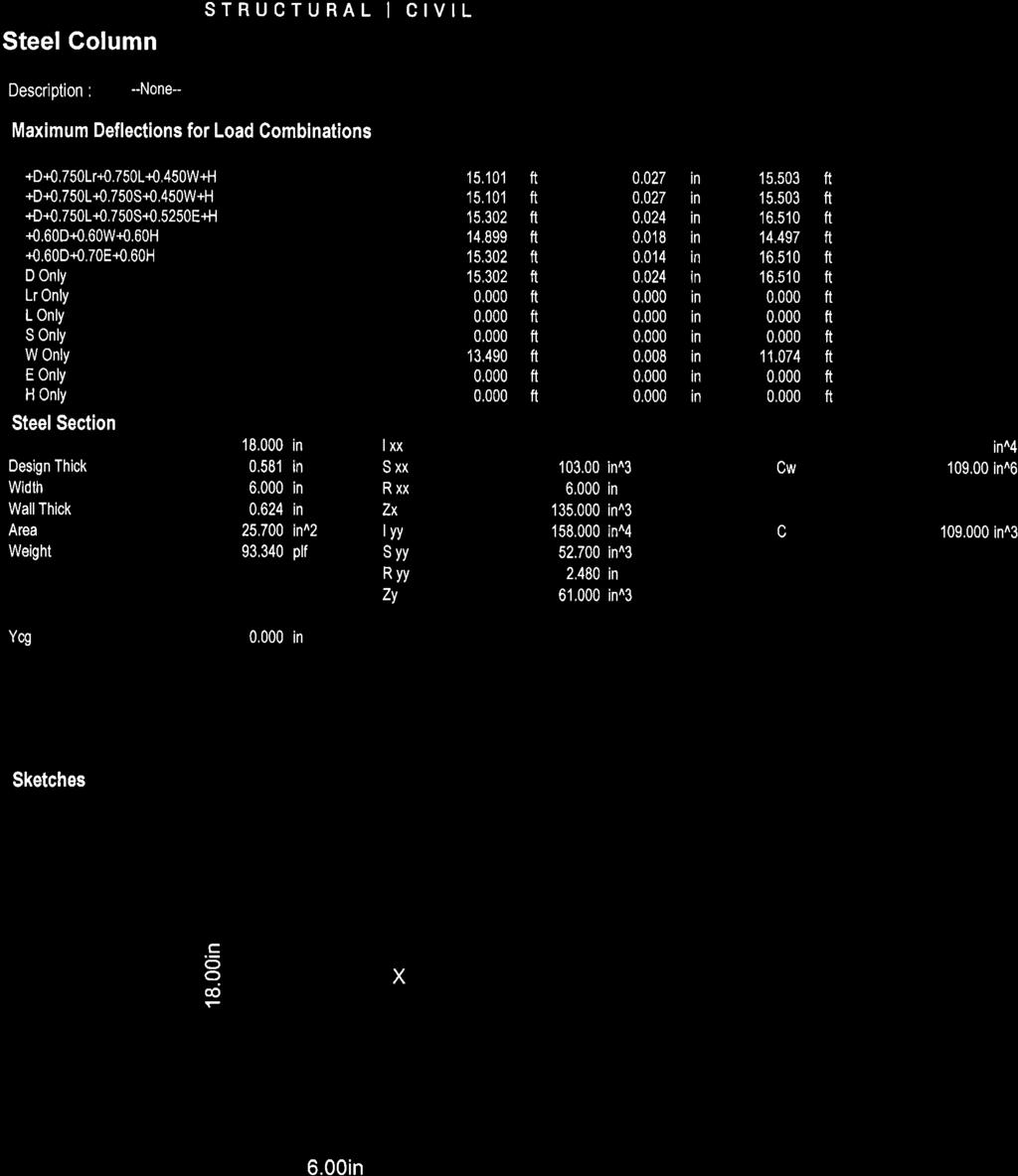
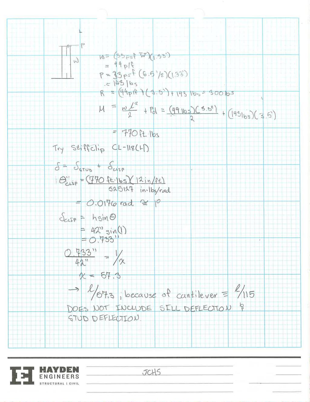
2 I am having a hard time conforming with the EOR s response to our drawings for the Junction City HS project. Please see the following:. Stacking ±0 windows over the top of ±30 windows is difficult to accomplish with light gauge framing. We typically frame long-span windows with soffits to help us deal with deflection and strength issues. We may be able to construct the upper windows (0 and 5 ) with thick cold-formed framing, on the scale of 97-mil and 8-mil, however; carrying these loads down to the bottom windows is problematic. I attached some calcs that run through the numbers up until I got to the out-of-plane design for the header at this point I could not get anything to work so I switched to modeling as an HSS. Even using an HSS 8x6x5/8 would not meet the ¾ max deflection criteria for windows (OSSC 403.3).. We may be able to frame the upper level windows that do not stack with other windows with standard framing, however; these headers would end up being 97-mil & 8-mil assemblies. 3. In conjunction with Item, since traditionally framed headers don t work, the alternative we propose is to frame the windows similarly to exterior soffits by hanging them off the structure. In order to do this, however, we would need () connection points for our studs. Above the upper level windows, the only option is the bottom of the beams. This would also require hanging studs off the bent plate above, which may be problematic for the EOR. 4. Moment clips do not meet the deflection requirements for the brick walls. These clips are usually very flexible. The original calculation package ran through a single clip, at which point I abandoned the moment clips, however; I went ahead and ran a similar calc for The Steel Networks stiffest 6 clip. The resulting deflection is far from the l/600 that we re looking for. Please note that the calculation I ran only considered the deflection due to the rotation of the stud about the clip and do not take into account the additional deflection of the stud and the deflection of the window sill. This is also attached. a. Using the moment clips results in an extremely high tension value (about 5 kips, Wind Load, Seismic load will be higher due to brick), this is difficult to accomplish with a single post-installed anchor. The anchors may need to be cast-in-place. I also attached a PDF that also notes these issues and clarifies some of our intent. With this in mind, please let me know how we should proceed. Please don t hesitate to give me a call if you have any questions. Vince Mallada Structural Designer 480 SW 68th, Tigard, OR (503)

3 REG I STE RE D P R O STRUCTURA L E N G I FESS N E E R 8,55 I ON AL DA S E RR P O T. OREGON N 0, R. 0 0 Y HA EN D GENERAL STRUCTURAL NOTES: BUILDING CODE: CONFORM TO THE 04 OREGON STRUCTURAL SPECIALTY CODE. DESIGN CRITERIA: DESIGN WAS BASED ON THE STRENGTH AND DEFLECTION CRITERIA GIVEN ON THE SPECIFICATIONS SECTION (COLD FORMED METAL FRAMING) PROVIDED BY DLR GROUP. THE FOLLOW CRITERIA WERE USED FOR DESIGN MINIMUM OUT OF PLANE DEFLECTION: L/600 - BRICK L/40 - METAL WALL PANEL, SINGLE-PLY MEMBRANE VERTICAL DEFLECTION GAP: '' SEISMIC LOADS: SITE CLASS= D USE GROUP= III SITE DESIGN CATEGORY=D IMPORTANCE FACTOR=.0 SDS= 0.87 Ss VALUE. SDS =.67 NOTE: THESE DRAWINGS ARE FOR THE DESIGN AND CONNECTIONS OF THE LIGHT GAUGE METAL STUDS ONLY. STRUCTURAL ELEMENTS, ARCHITECTURAL ELEMENTS, FINISHES AND FIREPROOFING SHOWN ON THESE DRAWINGS ARE FOR REFERENCE ONLY AND MAY NOT ACCURATELY REFLECT THE BUILDING AS IT IS REQUIRED TO BE CONSTRUCTED PER THE CONSTRUCTION DOCUMENTS AND REVISIONS. ALL ELEVATIONS, PLANS, SECTIONS, AND DIMENSIONS SHOULD BE VERIFIED WITH THE ARCHITECTURAL DRAWINGS. HAYDEN CONSULTING ENGINEERS DOES NOT ASSUME ANY RESPONSIBILITY FOR THE ADEQUACY OF THE PRIMARY STRUCTURE AND FOUNDATION DESIGN. HAYDEN CONSULTING ENGINEERS RECOMMENDATIONS ARE MINIMUM REQUIREMENTS FOR SSMA MEMBER SIZES AND SPACING THAT ARE ADEQUATE FOR THE GIVEN LOADING CONDITIONS AS SPECIFIED IN THE DESIGN CRITERIA. HEAVIER GAUGES AND TIGHTER SPACING MAY BE SUBSTITUTED. NOTE: WINDOW MANUFACTURER TO PROVIDE " VERTICAL DEFLECTION GAP. AREA OF WORK 480 sw 68th. Ave., Tigard, Oregon 973 (503) p (503) f WIND LOADS: WIND SPEED= 30 MPH - 3 SECOND GUST EXPOSURE= B IMPORTANCE FACTOR= Iw=.0 DESIGN WORK : THE STRUCTURE WHICH SUPPORTS THE LIGHT GAUGE METAL FRAMING IS DESIGNED BY DLR GROUP AND IS ASSUMED TO BE STRUCTURALLY ADEQUATE TO SUPPORT THE GRAVITY AND LATERAL FORCES EXERTED ON IT BY THE LIGHT GAUGE METAL FRAMING AND VENEER SYSTEMS. METAL STUDS: LIGHT GAUGE METAL STUDS SHALL BE OF THE SIZE AND TYPE AS SHOWN ON THE DRAWINGS. THE METAL STUDS SHALL BE MANUFACTURED BY A MEMBER OF THE STEEL STUD MANUFACTURERS ASSOCIATION (SSMA). MINIMUM STUD THICKNESS SHALL BE 43 MIL (8 GA.), UNLESS NOTED OTHERWISE ON THE DRAWINGS. Fy=50,000 PSI FOR 54, 68, AND 97 MIL (6, 4 AND GA.) STUDS. Fy=33,000 PSI FOR 33 AND 43 MIL (0 GA. AND 8 GA.) STUDS. ALL FIELD CUTTING OF STUDS MUST BE DONE BY SAWING OR SHEARING. TORCH CUTTING OF COLD-FORMED MEMBERS IS UNACCEPTABLE. NO NOTCHING OR COPING OF STUDS IS ALLOWED, UNLESS NOTED OTHERWISE WITHIN THE DRAWINGS. SPLICING OF WALL STUDS IS NOT ALLOWED, UNLESS NOTED OTHERWISE WITHIN THE DRAWINGS. VICINITY MAP N.T.S. FRAMING FABRICATOR IS TO ENSURE PUNCH OUT ALIGNMENT WHEN ASSEMBLING LATERAL BRACING AND FIELD CUTTING STUDS TO LENGTH. LATERAL BRACING MUST BE INSTALLED AT THE TIME THE WALL IS ERECTED. INSTALL HORIZONTAL BRIDGING OR "x0 GAUGE STRAPPING AND HORIZONTAL STUD 8'-0" O/C IN CURTAIN-WALL STUDS NOT MORE THAN 48" VERTICALLY APART IF SHEATHING IS NOT APPLIED TO EACH FACE. (UNLESS NOTED OTHERWISE ON DRAWINGS). GYPSUM WALL BOARD SHALL BE APPLIED TO EACH FACE OF STUD AND FASTENED AT A MAXIMUM OF " O/C UNLESS NOTED ON THE ARCHITECTURAL DRAWINGS. CONNECTIONS: FRAMING CONNECTORS SHALL BE MANUFACTURED BY THE STEEL NETWORK UNLESS NOTED OTHERWISE. FASTENERS SHALL BE CORROSION RESISTANT COATED, SELF-DRILLING, AND SELF-TAPPING SCREWS. UNLESS NOTED OTHERWISE ON THE DRAWINGS. THE SCREWS SHALL BE HILTI KWIK-PRO SELF DRILLING/SELF TAPPING SCREW (ICC-ES #96) AND HAVE A LOW PROFILE HEAD BENEATH SHEATHING AND STANDARD HEAD ELSEWHERE. A AA B BB N 0.8N N 3N 4N 5N 6N 7N N 0 AA BB A A.7 B SCREWS SHALL HAVE 3 4'' (MINIMUM) CLEARANCE FROM ALL EDGES OF THE STEEL MEMBER. B.5 SCREW SPACING SHALL NOT BE LESS THAN 3x THE NOMINAL SCREW DIAMETER. PENETRATION OF SCREWS THROUGH JOINED MATERIAL SHOULD NOT BE LESS THAN THREE (3) EXPOSED THREADS. WHERE ABLE, INSTALL SCREWS FROM THE THINNER MATERIAL TO THE THICKER MATERIAL. SCREWS SHALL BE INSTALLED AND TIGHTENED IN ACCORDANCE WITH THE SCREW MANUFACTURER'S RECOMMENDATIONS. WELDS: ALL WELDED CONNECTIONS ARE TO BE PERFORMED IN ACCORDANCE WITH THE LATEST VERSION OF AWS D.3 SPECIFICATIONS FOR WELDING SHEET STEEL IN STRUCTURES. SEE AWS D9.0 WELDING ZINC COATED STEEL AND ANSI STANDARD Z49. FOR INFORMATION REGARDING SAFE WELDING PROCEDURES. WELDERS SHALL BE AWS CERTIFIED FOR COLD-FORMED METAL WELDING. WELDING ELECTRODES SHALL BE E70XX. WELDING IS ONLY ACCEPTABLE ON MATERIAL 54 MIL. (6 GA.) OR THICKER. MINIMUM WELD THROAT THICKNESS MUST MATCH OR EXCEED THE BASE STEEL THICKNESS OF THE THINNEST CONNECTED PART, UNLESS NOTED OTHERWISE ON DRAWINGS. IN WELDING, THE ZINC COATING ON STEEL FRAMING WILL BE BURNED AWAY; THEREFORE A ZINC RICH PAINT MUST BE APPLIED TO THE WELD AREA TO PROVIDE ADEQUATE CORROSION RESISTANCE. POWER ACTUATED FASTENERS: ALL POWER ACTUATED FASTENERS (PAF'S) SHALL BE HILTI 'X-U UNIVERSAL KNURLED SHANK FASTENER' WITH PLASTIC WASHERS AND A 0.57'' SHANK DIAMETER (ICC - ESR #69). C CC DD D EE FF F G " STUD WALL CC.0 DD EE FF C D D. E F F.9 G PROJECT: JUNCTION CITY HIGH SCHOOL 35 MAPLE ST. JUNCTION CITY, OREGON WHEN INSTALLED INTO STEEL SUBSTRATE PAF'S SHALL HAVE A MINIMUM SPACING OF '' BETWEEN FASTENERS AND A MINIMUM EDGE DISTANCE OF ''. THE FASTENER SHALL BE DRIVEN TO WHERE THE POINT HAS PENETRATED THE STEEL SUBSTRATE UNLESS NOTED OTHERWISE. GG N. GG WHEN INSTALLED INTO CONCRETE SUBSTRATE PAF'S SHALL HAVE A MINIMUM SPACING OF 4'' BETWEEN FASTENERS AND A MINIMUM EDGE DISTANCE OF 3''. THE CONCRETE THICKNESS OF THE SUBSTRATE MATERIAL SHALL BE A MINIMUM OF 3x THE PAF'S EMBEDMENT DEPTH. N N 3N 4N 5N 6N INSPECTION: SPECIAL INSPECTIONS: IN ACCORDANCE WITH CHAPTER 7 OF THE OREGON STRUCTURAL SPECIALTY CODE AND APPLICABLE SECTIONS OF THE PROJECT SPECIFICATIONS. SPECIAL INSPECTIONS ARE TO BE PERFORMED BY AN INDEPENDENT TESTING LABORATORY EMPLOYED BY THE OWNER FOR THE FOLLOWING AREAS OF WORK: HH HH A. VERIFICATION OF METAL STUD SIZE, STUD SPACING, AND STUD GAUGE. B. VERIFICATION OF FRAMING CONNECTORS. C. FIELD WELDS. D. POST INSTALLED ANCHORS. JJ 8N 9N 0 6 JJ SHEET CONTENT GENERAL INFO JOB No. 73 DRAWN CHECKED CLM VM/DH DATE REVISIONS /4/07 :5 PM SHEET S.0 OF 5
4 REG I STE RE D P R O STRUCTURA L E N G I FESS N E E R 8,55 I ON AL D C B.5 B A.7 A DA S E RR P O T. OREGON N 0, R. 0 0 Y HA EN D S3. LEVEL 0 4' - 0" '-0" CORNER ZONE SEE ASI TO BE ISSUED FOR DETAIL AT THIS LOCATION WITH STEEL BEAM IN THE PLANE OF LEVEL 0THE STUD WALL 4' - 0" 480 sw 68th. Ave., Tigard, Oregon 973 (503) p (503) f 4 S3. 4 S3. 4 S3. LEVEL 0 00' - 0" 6" STUD WALL HSS FRAME LEVEL 0 00' - 0" EAST ELEVATION (AREA B).0 EAST ELEVATION (AREA CANOPY) SCALE: 8''='-0''.0 SCALE: 8''='-0'' GG G F.9 F E D. D H3 600T " STUD WALL '-0" CORNER ZONE A B S4 ROOF 8' - 0" '-0" CORNER ZONE 8 J4 FULL HT AT GRID 8 LEVEL 0 4' - 0" LEVEL 0 4' - 0" S3. TYP 4 S3. 3 EAST ELEVATION (AREA C SOUTH).0 FULL HT CMU AT WALL EAST OF GRID 0 LEVEL 0 00' - 0" 4 WEST ELEVATION SCALE: 8''='-0''.0 GG LEVEL 0 00' - 0" SCALE: 8''='-0'' PROJECT: JUNCTION CITY HIGH SCHOOL 35 MAPLE ST. JUNCTION CITY, OREGON C D E F G ROOF 8' - 0" LEVEL 0 4' - 0" LEVEL 0 00' - 0" LEVEL 0 4' - 0" LEVEL 0 00' - 0" J4 CONSTRUCTION JOINTS STUD KEYNOTES: S- HEADER KEYNOTES: H- S. 600S " O/C. 600S 6" O/C S3. 600S 6" O/C S4. 600S 6" O/C JAMB KEYNOTES: J- J. () 600S 6-54 BACK-TO-BACK J. () 600S 6-68 BACK-TO-BACK J3. () 600S BACK-TO-BACK J3. () 600S BACK-TO-BACK H. () 800S 6-54 W/ () 600T H. () 600S 6-54 W/ () 600T H3. () 600S 6-43 W/ () 600T REFERENCE DETAILS 0/ SHEET CONTENT JOB No. 73 DRAWN CHECKED CLM VM/DH DATE REVISIONS ELEVATIONS /4/07 :5 PM 5 WEST ELEVATION (SOUTH).0 6 WEST ELEVATION (AREA C SOUTHEAST) SCALE: 8''='-0''.0 -REFERENCE 9/ SCALE: 8''='-0'' SHEET.0 OF 5
5 REG I STE RE D P R O STRUCTURA L E N G I FESS N E E R 8,55 I ON AL 9 0N N N 3N 4N 5N 6N 7N 8N 9N 0 '-0" CORNER ZONE PROVIDE HEADER CALLOUT, TYP NOT CORRECT. ATTACH PER DETAIL 4/S4.4 '-0" CORNER ZONE '-0" CORNER ZONE STUD WALL PER DETAIL 5/S4.3 DA S E RR P O T. OREGON N 0, R. 0 0 Y HA EN D '-0" CORNER ZONE S S3. S3. S3. S3. S3 600R W/ () #8 SCREW EACH STUD S S3 '-0" CORNER ZONE LEVEL 0 4' - 0" 480 sw 68th. Ave., Tigard, Oregon 973 (503) p (503) f S LEVEL 0 00' - 0" SOUTH ELEVATION (AREA F). PROVIDE PER DETAIL 4/S4. SCALE: 8''='-0'' 0 9N 8N 7N 6N 5N 4N 3N N N '-0" CORNER ZONE NOT ACCEPTABLE TO ATTACH TO BOTTOM FLANGE OF UNBRACED BEAM. PROVIDE CONNECTION PER DETAIL 4/S4.4 AND LIGHT GAGE HEADER AS SHOWN ON SHEET A9.4 PROVIDE HEADER CALLOUTS, TYPICAL 3 S3. 8 S S3. 8 S3. PROVIDE JAMB REINFORCING CALLOUT, TYPICAL '-0" CORNER ZONE S LEVEL 0 4' - 0" S 4 S3. H 4 S 4 NORTH ELEVATION. AT GRID E PROVIDE PER DETAIL 35/S4. J '-0" CORNER ZONE 3 PROVIDE PER DETAIL 4/S4. 3 LEVEL 0 00' - 0" SCALE: 8''='-0'' PROJECT: JUNCTION CITY HIGH SCHOOL 35 MAPLE ST. JUNCTION CITY, OREGON N N 0N 9 '-0" CORNER ZONE '-0" CORNER ZONE 4 S3. '-0" CORNER ZONE LEVEL 0 4' - 0" LEVEL 0 00' - 0" CONSTRUCTION JOINTS STUD KEYNOTES: S- HEADER KEYNOTES: H- S. 600S " O/C. 600S 6" O/C S3. 600S 6" O/C S4. 600S 6" O/C JAMB KEYNOTES: J- J. () 600S 6-54 BACK-TO-BACK J. () 600S 6-68 BACK-TO-BACK J3. () 600S BACK-TO-BACK J3. () 600S BACK-TO-BACK H. () 800S 6-54 W/ () 600T H. () 600S 6-54 W/ () 600T H3. () 600S 6-43 W/ () 600T REFERENCE DETAILS 0/ SHEET CONTENT JOB No. 73 DRAWN CHECKED CLM VM/DH DATE REVISIONS ELEVATIONS /4/07 :5 PM 3 NORTH ELEVATION (AREA B). SCALE: 8''='-0'' -REFERENCE 9/ SHEET. OF 5
 # SCREWS & () HILTI ''X-U' PAF's @ 4\" THICK STEEL, VERIFY SLAB EMBED, 600T 50-54 W/ () #8 SCREWS TO EA.")
6 4" BRICK / CMU VENEER, ATTACHMENT HULTI 'HUS-EZ' 4" Ø x 6" O/C ALT: 3 8" Ø x 3" O/C -OR- " Ø x 4 4" 48" O/C 600T 50-(MATCH STUD) STUD PER ELEV. SCAFCO 'PLC4' CLIPS W/ (3) # SCREWS & () HILTI ''X-U' 4" THICK STEEL, VERIFY SLAB EMBED, 600T W/ () #8 SCREWS TO EA. STUD STEEL STANCHION,, 6'-0" O/C MAX, VERIFY 600S 6-43 EACH SIDE W/ HILTI 'X-U' " O/C & () TOP NO STANCHIONS PROVIDED. STUD MFR TO PROVIDE KNEE WALL MOMENT CLIPS AT LONG WINDOWS AS REQUIRED BY DETAIL 4/S3.. '-0" STUD PER ELEV. 600T W/ () #8 SCREWS TO EACH STUD 600T W/ () #8 SCREWS TO EACH STUD SCAFCO 'AC550' CLIPS SLAB WF BEAM, VERIFY 4" MIN. FLANGES SCAFCO 'AS' STRUT W/ () #0 SCREWS TO STUD & HILTI 'X-U' PAF's FULLY PENETRATE PER ICC REPORT WINDOW MANUF. TO PROVIDE DEFLECTION WINDOWS VERIFIED " x 33 MIL STRAP ON THE SIDE WITHOUT PLYWOOD OR GYPSUM SHEATHING PER ELEV. TRACK BLOCKING SIZE & GAUGE TO MATCH METAL STUDS. 8'-0'' O/C & AT EACH END OF WALL. METAL TRACK, SEE PLAN FOR SIZE & LOCATION METAL TRACK. SEE PLAN FOR SIZE & LOCATION METAL STUDS, SEE PLAN FOR SIZE & LOCATION JAMB STUD L x x (MATCH SILL GAUGE) W/ (3) #0 SCREWS EACH LEG STE I REG DA S RR RE E P O D T. N P R 0, R. O STRUCTURA L E N G I OREGON FESS N E E R 8, Y HA I D ONAL EN 480 sw 68th. Ave., Tigard, Oregon 973 (503) p (503) f TYP. BOTTOM CONNECTION SLAB EDGE SCALE: 3 4''='-0'' SCALE: 3 4''='-0'' 3 WALL ELEVATION N.T.S. 4 SLAB EDGE SCALE: 3 4''='-0'' 5 WALL ELEVATION N.T.S. 6 TYPICAL SILLS SCALE: ''='-0'' TYPICAL STUD WALL LOCATIONS VERIFY PER PLAN #8 SELF TAPPING 6" O/C TYPICAL STUD () # SCREWS EACH STUD, TYP. () # SCREWS EACH STUD, TYP. # " O/C TRACK HEADER DEEP LEG TRACK HEADER () # SCREWS EACH STUD, TYP. BOX BEAM HEADER # 8'' O/C PLAN AT WALL CORNER PLAN AT WALL INTERSECTION WALL LOCATIONS VERIFY PER PLAN #8 SELF TAPPING 6" O/C PLAN AT HSS COLUMN WALL LOCATIONS VERIFY PER PLAN 0.57" Ø 4" O/C METAL STUD PER ELEVATION 6'' TRACK x '' FLANGES x STUD GA. W/ () #8 SCREWS EACH STUD & 8'' O/C STAGGERED INTO HSS HSS BEAM OR " GAP HSS BEAM OR PLATE, VERIFY 4" THICK MIN. SLOTTED 600T W/ () #8 SCREWS EA. STUD & 8'' O/C STAGGERED INTO HSS METAL STUD PER ELEVATION BUILT-UP JAMB STUD PER ELEVATION ALTERNATE # 8" O/C 8ga TRACK OPENING SIDE # 8" O/C STAGGERED BUILT-UP JAMB STUD PER ELEVATION # SCREW EACH SIDE BEND FLANGE DOWN W/ () # SCREWS FULL HEIGHT JAMB STUD EXTEND STUD WEBS OVER JAMB STUD ON EA. SIDE & CONNECT W/ (3) # SCREWS L x x STUD WIDTH x (MATCH HDR GAUGE) W/ (3) # SCREWS EACH LEG FULL HEIGHT JAMB STUD 7 TYPICAL CORNERS NTS 8 HSS SCALE: ''='-0'' 9 TYPICAL JAMB STUDS SCALE: /'' = '-0'' 0 TYPICAL HEADERS SCALE: ''='-0'' STEEL FRAMING 'STIFF CLIP CL ' W/ (4) # SCREWS & 5 8"Ø x 3 4" EMBED HILTI 'HUS-EZ' ANCHOR 400S " O/C ALONG STRONG BACK W/ () # TO STRONG BACKS, TYP. 54 MIL. ZEE 4" O/C W/ () HILTI 'X-U' PAF's EA. HSS BEAM CEILING, 400S 4" O/C MAX. CONNECT TO STRONG BACKS W/ 54 MIL. ANGLE & () #8 SCREWS EA. LEG, TYP. 400S 6-54 STRONG 8'-0" O/C MAX. & 4" MAX. FROM ENDS 400T PERIMETER TRACK W/ () #8 EA. JOIST EXTERIOR CEILING SECTION N.T.S. EXTERIOR CEILING SECTION N.T.S. SHEET CONTENT PROJECT: JUNCTION CITY HIGH SCHOOL 35 MAPLE ST. JUNCTION CITY, OREGON DETAILS JOB No. 73 DRAWN CHECKED CLM VM/DH DATE REVISIONS /4/07 :5 PM SHEET OF 5
7 VERIFIED BENT PLATE OR HSS PER STRUCT, STRUCT. TO VERIFY CAPACITY FOR HANGING STUDS SCAFCO 'MA550 CLIP W/ (4)#0 SCREWS & () HILTI 'X-U' PAFs 0.57" Ø INTO KICKER LOCATIONS 43mil TRACK TSN 'SLB600' W/ (3) # SCREWS & HILTI 'X-U' PAF's TO STEEL (ALT.: SCAFCO 'PLC4' W/ (3) 'X-U' PAF's) STE I REG DA S E RR P O D RE T. N P R 0 R., O STRUCTURA L E NG I OREGON FESS N E E R 8, Y HA I D ON AL EN ANGLE PER STRUCT. 600S ANGLE LOCATIONS, INFILL STUDS PER ELEV. 600T W/ () #8 TO EACH STUD " 3" () HILTI 'X-U' PAF's INTO 4" MIN. STEEL '-0" MAX WINDOW MANUF. TO PROVIDE DEFLECTION CONNECTION 68mil SLOTTED DEFLECTION TRACK W/ HILTI 'X-U' 6" O/C & () #8 SCREWS TO EACH STUD STUD PER ELEV. 3 8 " BENT PLATE, VERIFY WF PER STRUCT. 600T W/ HILTI 'X-U' 6" O/C & () #8 SCREWS TO EACH STUD 36 KICKER LOCATIONS WINDOW MANUF. TO PROVIDE SLIP CONNECTION 400S 6-43 KICKER W/ () HILTI 'X-U' PAF's INTO 4'-0" O/C, VERIFY 4" THICK MIN. & (3) # SCREWS TO STUD 600S 6-43 W/ () #0 SCREWS TO EACH STUD KICKER LOCATION ONLY STUD PER ELEVATION 43 mil TRACK HSS PER STRUCTURE TSN 'LB36' CLIP W/ (3) # SCREWS & () HILTI 'X-U' PAF's TO 4" MIN. STEEL (ALT.: SCAFCO 'AC550' W/ (3) # & () 'X-U' PAF's) WOOD FRAMING OVERHANG S3. DETAIL N.T.S. S3. 3 DETAIL N.T.S. S3. N.T.S. 4 DETAIL S3. N.T.S. SHEET CONTENT DETAILS PROJECT: 480 sw 68th. Ave., Tigard, Oregon 973 (503) p (503) f JUNCTION CITY HIGH SCHOOL 35 MAPLE ST. JUNCTION CITY, OREGON JOB No. 73 DRAWN CHECKED CLM VM/DH DATE REVISIONS /4/07 :5 PM SHEET S3. OF 5


8

9

10
11
12

13
14
15
16
17

18
19
20
21
22
23
24
25
26

27
28
29
30
31
32
33
RFI Transmittal. Junction City SD High School RFI150. RFI #150: Cold Framing Submittal EOR Response - Mid Valley Commercial Construction
 RFI Transmittal DLR Group PROJECT: Junction City SD High School 74-66-0 DATE SENT: 0/6/07 SUBJECT: RFI #50: Cold Framing Submittal EOR Response - Mid Valley Commercial Construction RFI ID: RFI50 TYPE:
Connectors for Cold-Formed Steel Curtain-Wall Construction
 The expiration date of this document has been extended until 2/3/3. Introducing Connectors for Cold-Formed Steel Curtain-Wall Construction Code Listed: IAPMO ES ER-238 (800) 999-5099 www.strongtie.com
FIRE STATION NO TH STREET NORTH ST. PETERSBURG, FL M-1 SCOPE OF WORK SYMBOL DESCRIPTION SYMBOL DESCRIPTION HVAC SYMBOL LEGEND
 HVAC SYMBOL LEGEND HVAC PIPING AND VALVES LEGEND HVAC GENERAL NOTES SCOPE OF WORK SYMBOL DESCRIPTION SYMBOL DESCRIPTION SYMBOL DESCRIPTION SYMBOL DESCRIPTION PHASING OF WORK HVAC ABBREVIATIONS ABBREVIATION
Connectors for Cold-Formed Steel Curtain-Wall Construction
 Introducing Connectors for Cold-Formed Steel Curtain-Wall Construction Code Listed: IAPMO ES ER-238 (800) 999-5099 www.strongtie.com Our Newest Product Line for Cold-Formed Steel Framing Simpson Strong
Shearwall System Installation Guide
 Shearwall System Installation Guide Complete HFX product listing with dimensions, weights, connectors, typical installations and accessories. Also includes Hardy Frame Moment Frame information. Easy as
Introducing AJSTM INSTALLATION GUIDE USA. 8 th Edition USA
 The SIMPLE FRAMING SYSTEMSM INSTALLATION GUIDE USA for Floors This Installation Guide is intended to provide general information for the designer and end-user. For further information, please refer to
Fastener Schedule. a, b, c. FASTENER Roof 3-8d (2 1 / ) / ) 3-10d. 3-10d ( ) 3-16d box nails. (3 1 2 toe nails on one side
 / ) 3-10d. 3-10d ( ) 3-16d box nails. (3 1 2 toe nails on one side") ITEM 1 DESCRIPTION OF BUILDING ELEMENTS Blocking between joists or rafters to top plate, toe 2 Ceiling joists to plate, toe 3 4 5 6 Ceiling joists not attached to parallel rafter, laps over partitions,
ITEM 1 DESCRIPTION OF BUILDING ELEMENTS Blocking between joists or rafters to top plate, toe 2 Ceiling joists to plate, toe 3 4 5 6 Ceiling joists not attached to parallel rafter, laps over partitions,
PLAN CEILING FRAMING PLAN CEILING JOIST SCHEDULE. Tenant Improvements. UNLV Police Station Maryland Parkway.
 TYPICAL HEADER, SEE DETAIL 3/ 4 1 6 2 CEILING FRAMING PLAN SCALE: 3/16" = 1'-0" 2 2 4 600S162-43 FLAT BRACE, 4 CEILING JOIST, SEE SCHEDULE, BOXED BEAM: (2) 600S162-54 + (2)14GA TRACKS 2 CEILING JOIST SCHEDULE
COLD-FORMED METAL FRAMING INSPECTION REPORT SUMMARY
 COLD-FORMED METAL FRAMING INSPECTION REPORT SUMMARY Inspector: Section 05400 Name: Date: Company: Address: City: State: Zip code: Phone: Fax: E-mail: Project: Project Name: Location: Contractor: Phone:
 JOIST DETAILS Plate nail, 16d (0.15" x 1 ") at 1 on-center Blocking panel: 1 1 8" TJ Rim Board, 1 1 TimberStrand SL or TJI joist Toe nail, 10d (0.11" x ") at on-center A1 CS BEAM DETAILS L1 eb stiffener
Connectors for Cold-Formed Steel Curtain-Wall Construction
 Special Section Introducing Connectors for Cold-Formed Steel Curtain-Wall Construction Code Listed: IAPMO ES ER-238 (800) 999-5099 www.strongtie.com 240 Our Newest Product Line for Cold-Formed Steel Framing
GLOSSARY OF TERMS SECTION 8
 GLOSSARY OF TERMS SECTION 8 Anchor Bolt Angle Base Plate Bay Blocking CCB Centerline Chord Cladding Clip Closure Strip An A-307 steel bolt embedded in the concrete footing to anchor the base plate of the
T-BRACE / I-BRACE DETAIL WITH 2X BRACE ONLY
 August 10, 2010 T-BRACE / I-BRACE DETAIL WITH 2X BRACE ONLY ST - T-BRACE 2 R MiTek Industries, Chesterfield, MO Page 1 of 1 Note: T-Bracing / I-Bracing to be used when continuous lateral bracing is impractical.
3.1 General Provisions
 WOOD FRAME CONSTRUCTION MANUAL 107 3.1 General Provisions 3.1.1 Prescriptive Requirements The provisions of this Chapter establish a specific set of resistance requirements for buildings meeting the scope
3. Are component and cladding design pressures consistent with ASCE 7 for the wind speed and exposure category (ASCE 7 Fig. 6-3)?
?") Mobile County Public Works Residential Plan Reviewers Checklist For Structural Requirements of Wood Framed Residences Recommendation: Permit as Noted Revise Plans and Resubmit MCPW Ref. No. Design Criteria:
Mobile County Public Works Residential Plan Reviewers Checklist For Structural Requirements of Wood Framed Residences Recommendation: Permit as Noted Revise Plans and Resubmit MCPW Ref. No. Design Criteria:
KS SERIES - VERTICAL INSTALLATION
 CS-DS-01-KSV CS DISCLAIMER CS-PJ-01-KSV KS42SL EXPANDED PANEL JOINT CS-PJ-02-KSV KS42SL ENGAGED PANEL JOINT CS-PJ-03-KSV KS45SL EXPANDED PANEL JOINT CS-PJ-04-KSV KS45 FLAT ENGAGED PANEL JOINT CS-PJ-05-KSV
STRUCTURAL ATTACHMENTS
 Brace Structural Attachment Selection Procedure ) Determine structure to be attached to from the following: A) Concrete B) Wood Beam C) Structural Steel 2) Reference structure connection type from Appendix
Typical Deck Details
 Botetourt County guard decking ledger board fasteners existing house floor construction guard post attachment ledger board attachment to existing house s footing beam -to-beam connection post-to-beam connection
10x12 FOUNDATION GUIDE 10x12 TRICO AND FLORA SHEDS
 10x12 FOUNDATION GUIDE 10x12 TRICO AND FLORA SHEDS 10x12 WOOD SKID FLOOR FLOOR SYSTEM FOR 10x12 TRICO AND FLORA SHEDS RAW MATERIALS LIST: 2 (9) FLOOR FRAMING AND SHEATHING: 1) BAND BOARD 2 x 6 x 12 PRESSURE
ICC-ES Evaluation Report
 ICC-ES Evaluation Report www.icc-es.org (800) 423-6587 (562) 699-0543 ESR-2608 Reissued January 2016 This report is subject to renewal January 2017. A Subsidiary of the International Code Council DIVISION:
DW HORIZONTAL INSTALLATION
 AR-PJ-01-DW2H 2" HORIZONTAL PANEL JOINT AR-PJ-02-DW2H 2" VERTICAL PANEL JOINT AR-PJ-03-DW2H 3" HORIZONTAL PANEL JOINT AR-PJ-04-DW2H 3" VERTICAL PANEL JOINT AR-PJ-05-DW2H CUSTOM REVEAL AR-PJ-06-DW2H DW-2000S
AUXILIARY FRAMING AND ACCESSORIES
 CUSTOM CABINETS & RACKS STRUT AND ACCESSO- RIES JUNCTION KITS ANGLE AND BRACE KITS SPLICE KITS BRACE KITS INSTALLATION KITS WALL ANGLE KITS RUBBER END CAPS SUPPORT INSTALLATION AND SUPPORT KITS STANCHION
Typical Deck Details
 Based on the 2009 Michigan Statewide Building Code guard decking ledger board fasteners existing house floor construction guard post attachment ledger board attachement to existing house s footing beam
FASTENERS C O M P AT I B L E W I T H F E R O T I E S Y S T E M S. Which FERO Tie Systems Require Fasteners?
 FASTENERS C O M P AT I B L E W I T H F E R O T I E S Y S T E M S Which FERO Tie Systems Require Fasteners? Structural Actions: Fastener,, or Both? With the exception of FERO tie systems that are directly
APPLICATION FOR A BUILDING PERMIT
 APPLICATION FOR A BUILDING PERMIT City of San Jacinto 595 S. San Jacinto Ave San Jacinto CA 92583 95.487.7330 fax 95.654.9896 Must print legibly, submit (3) sets of building and plot plans. Fill out all
SECTION STRUCTURAL STEEL. A. PART A and DIVISION 1 of PART B are hereby made a part of this SECTION.
 SECTION 051200 PART 1 GENERAL 1.01 GENERAL REQUIREMENTS A. PART A and DIVISION 1 of PART B are hereby made a part of this SECTION. B. Examine all conditions as they exist at the project prior to submitting
Table of Contents F Series Frames
 Table of Contents F Series Frames How to Order Frames... F 1 F Series Spec Sheet... F 2 F Series Profiles 1 of 6... F 3 F Series Profiles 2 of 6... F 4 F Series Profiles 3 of 6... F 5 F Series Profiles
METALWORKS Linear (Interior & Exterior Applications)
") CEILING&WALL SYSTEMS Between us, ideas become reality METALWORKS Linear (Interior & Exterior Applications) Assembly and Installation Instructions 1. GENERAL 1.1 Product Description MetalWorks Linear is
CEILING&WALL SYSTEMS Between us, ideas become reality METALWORKS Linear (Interior & Exterior Applications) Assembly and Installation Instructions 1. GENERAL 1.1 Product Description MetalWorks Linear is
Lateral Support. Decks over 24 above grade require lateral support* *Exceptions to be discussed later
 Lateral Support Decks over 24 above grade require lateral support* *Exceptions to be discussed later Decking Types of Decking: -2x4s & 2x6s -five quarter span rated decking boards -Wood plastic composite
CARRIER OVERHANG 1'-0" MAX PANEL LENGTH 3'-0" MIN - 16'-0" MAX (RECOMMENDED) SPECIFICATIONS (unless noted otherwise)
 SPECIFICATIONS (unless noted otherwise)") DETAIL 5 32 5 " 27 32 " 6" OPTIONAL FLAT RECESSED CLOSURE 1 1 4 " 17 32 " 1 25 32 " OPTIONAL BUTTERFLY CLOSURE CARRIER OVERHANG 1'-0" MAX CARRIER SPAN 4'-0" 12 GA HANGER WIRE, BY OTHERS, NOT BY HUNTER
DETAIL 5 32 5 " 27 32 " 6" OPTIONAL FLAT RECESSED CLOSURE 1 1 4 " 17 32 " 1 25 32 " OPTIONAL BUTTERFLY CLOSURE CARRIER OVERHANG 1'-0" MAX CARRIER SPAN 4'-0" 12 GA HANGER WIRE, BY OTHERS, NOT BY HUNTER
Beam & Header Technical Guide. LP SolidStart LVL. 2900F b -2.0E. U.S. Technical Guide U.S. TECHNICAL GUIDE
 U.S. Technical Guide U.S. TECHNICAL GUIDE LP SolidStart LVL & Header Technical Guide 2900F b -2.0E Please verify availability with the LP SolidStart Engineered Wood Products distributor in your area prior
LEGACY REPORT. (800) (562) A Subsidiary of the International Code Council. *Revised September 2003
 (562) A Subsidiary of the International Code Council. *Revised September 2003") ICC-ES Evaluation Report ER-580* Reissued January 00 www.icc-es.org (800) 4-6587 (56) 699-054 A Subsidiary of the International Code Council Legacy report on the 997 Uniform Building Code DIVISION: 05
ICC-ES Evaluation Report ER-580* Reissued January 00 www.icc-es.org (800) 4-6587 (56) 699-054 A Subsidiary of the International Code Council Legacy report on the 997 Uniform Building Code DIVISION: 05
JVI Vector Connector
 The JVI Vector Connector User Guidelines 1 of 11 INTRODUCTION JVI designed the Vector Connector for use as shear and alignment connections between precast concrete elements such as double-tee flanges,
*Revised September 1, 2003
 LEGACY REPORT ER-580* Reissued January, 00 ICC Evaluation Service, Inc. www.icc-es.org Business/Regional Office # 560 Workman Mill Road, Whittier, California 9060 # (56) 699-054 Regional Office # 900 Montclair
Featuring TJ Rim Board and TimberStrand LSL
 #TJ-8000 SPECIFIER S GUIDE TRUS JOIST RIM BOARD Featuring TJ Rim Board and TimberStrand LSL Multiple thicknesses, grades, and products to cover all your rim board needs 1¼" Thickness matches lateral load
GlasRoc Sheathing Type X
 Wall / Fire-Rated Systems 3-5/8" (92 mm) Steel Studs ProRoc Steel Stud System 3-5/8" (92 mm) Steel Track 3-1/2" (89 mm) Glass Fiber or Mineral Wool Insulation GlasRoc Sheathing Type X UL Design U465 Cavity
CHAPMAN GRIFFIN LANIER SUSSENBACH ARCHITECTS, INC. ARCHITECT S ADDENDUM NO. 06
 CGLS A R C H I T E C T S CHAPMAN GRIFFIN LANIER SUSSENBACH ARCHITECTS, INC. 2500 Cumberland Parkway Suite 350 Atlanta, Georgia 30339 404.733.5493 (voice) 404.733.6804 (fax) www.cglsarchitects.com ARCHITECT
Hilti, Inc South 122 nd East Avenue Tulsa, OK
 Attached are page(s) from the 2013 Hilti North American Product Technical Guide Volume 1 Direct Fastening. For complete details on this product, including data development, product specifications, general
Exterior Wall Fastener Schedule
 City of Republic Community Development Department Exterior Wall Fastener Schedule REVISION DATE: JANUARY 2017 Design and construction (2012 IRC Section R602.3): Exterior walls of wood frame construction
FASTENERS BUILDING DEPARTMENT
 FASTENERS BUILDING DEPARTMENT 952-446-1660 WWW.CITYOFMINNETRISTA.COM This handout is intended only as a guide and is based in part on the 2015 Minnesota Residential Code, Minnetrista City ordinances, and
REPORT HOLDER: JAACO CORPORATION NORTHEAST 68 TH STREET, SUITE C-130 REDMOND, WASHINGTON EVALUATION SUBJECT:
 0 Most Widely Accepted and Trusted ICC-ES Evaluation Report ICC-ES 000 (800) 423-6587 (562) 699-0543 www.icc-es.org ESR-2961 Reissued 09/2017 This report is subject to renewal 09/2019. DIVISION: 05 00
UL Construction No. 254
 UL Construction No. Wind-Uplift - Class 90 (See Item No. ) / Fire Not Investigated Metal Roof Deck Panels* Snap-Clad No. MSG or No. MSG min. thickness coated steel panels. Panels in. wide max., 0 in. wide
ICC-ES Evaluation Report Reissued June 1, 2010 This report is subject to re-examination in one year.
 ICC-ES Evaluation Report ESR-2648 Reissued June 1, 2010 This report is subject to re-examination in one year. www.icc-es.org (800) 423-6587 (562) 699-0543 A Subsidiary of the International Code Council
Support Fastening. Support Fastening
 A variety of fastening systems may be used to connect steel deck to the supporting members. The type of fastening system used depends on the required diaphragm shear capacity, uplift capacity and the thickness
THE ENGINEERED WOOD ASSOCIATION
 D A T A F I L E APA Performance Rated Rim Boards A rim board is the wood component that fills the space between the sill plate and bottom plate of a wall or, in second floor construction, between the top
5/16" Flange nut. Bolt Keeper Plate (8" Sq. SYS.) (3) 1/2" x 3" Hex head connector zinc plated bolt w/ washers and nut. Anchor 3" sq. 7 Ga.
 (3) 1/2 x 3 Hex head connector zinc plated bolt w/ washers and nut. Anchor 3 sq. 7 Ga.") 2 1/2" x 2 1/2" x 10 Ga. 6" 5" 4" Variable Slipbase (8" Sq. SYS.) 5/16 Corner Bolt W/ nut 5/16" Flange nut Stub Insert (8" Sq. SYS.) Bolt Keeper Plate (8" Sq. SYS.) (3) 1/2" x 3" Hex head connector zinc
2 1/2" x 2 1/2" x 10 Ga. 6" 5" 4" Variable Slipbase (8" Sq. SYS.) 5/16 Corner Bolt W/ nut 5/16" Flange nut Stub Insert (8" Sq. SYS.) Bolt Keeper Plate (8" Sq. SYS.) (3) 1/2" x 3" Hex head connector zinc
Typical Deck Details Based on the City of Nixa Residential Deck Ordinance
 Typical Deck Details Based on the City of Nixa Residential Deck Ordinance The use of this package in lieu of submitted drawings applies to Single Span, Single Level, Residential Decks ONLY. Decks must
Shaft Wall SYSTEMS 210 INSTALLATION 211. Shaft Wall systems are fire rated non-load bearing walls used for shafts and service ducts.
 SYSTEMS 210 INSTALLATION 211 GENERAL REQUIREMENTS 211 FRAMING 212 PLASTERBOARD LAYOUT 213 PLASTERBOARD FIXING 214 CONSTRUCTION DETAILS 217 Shaft Wall Shaft Wall systems are fire rated non-load bearing
NORMAL WEIGHT CONCRETE TOTAL-LEWIS-DECK GYPSUM BOARD 2 OR 3-PLY COMPOSITE TOTALJOIST TOP CHORD CONNECTION
 GENERAL DETAILS 100 TYPICAL FLOOR CONSTRUCTION NORMAL WEIGHT CONCRETE WELDED WIRE MESH FIBERGLASS BATT INSULATION (OPTIONAL) 18 GAUGE TIE WIRE 7/8" RESILIENT CHANNEL NOTE: CEILING MAY ALSO BE SUSPENDED
Definitions and Design Considerations... W-CR-2
 General Information SECTION DIRECTORY Definitions and Design Considerations... W-CR-2 Combination Assembly Recommendations and Limitations Typical Sealant... W-CR-4 Single-Unit Opening... W-CR-4 Two-Way
THE BEST PRODUCTS, QUALITY, AND CUSTOMER SERVICE.
 PRODUCT CATALOG THE BEST PRODUCTS, QUALITY, AND CUSTOMER SERVICE. Our FrameRite Connectors Catalog details our line of high quality steel framing connectors. We know our customers depend on our quality
TENANT IMPROVEMENT 16 FEBRUARY WEST 27TH STREET, 4TH FLOOR 100% CD OWNER/BID ADD 1-03/08/2018
 SECTION 055000 - PART 1 - GENERAL 1.1 RELATED DOCUMENTS A. Drawings and general provisions of the Contract, including General and Supplementary Conditions and Division 01 Specification Sections, apply
Submittal / Substitution Request
 Submittal / Substitution Request SUBMITTED TO: To: Firm: Project: Submitted Product: SIMPSON STRONG-TIE POWDER ACTUATED FASTENERS Specified Product: Section: Page: Detail/Sheet : Description of Application:
ESR-2403 Reissued October 1, 2009 This report is subject to re-examination in one year.
 ICC-ES Evaluation Report ESR-403 Reissued October, 009 This report is subject to re-examination in one year. www.icc-es.org (800) 43-6587 (56) 699-0543 A Subsidiary of the International Code Council DIVISION:
INSTALLATION SHOP DRAWINGS FOR MINNEAPOLIS, MN
 MINNEAPOLIS, MN 2-0- 2-- General Notes Abbreviations Deviations from Architectural Specifications Deviations from Architectural Drawings ALUM. = ALUMINUM B.O. = BY OTHERS CONT. = CONTINUOUS. = CLEARANCE
City of Virginia Beach, Virginia Typical Deck Details
 City of Virginia Beach, Virginia Typical Deck Details Based on the 2012 Virginia Residential Code The design details in this document apply to residential, single-level decks only. Construction cannot
SECTION STRUCTURAL STEEL FRAMING PART 1 - GENERAL 1.1 RELATED DOCUMENTS
 SECTION 05 12 00 - STRUCTURAL STEEL FRAMING PART 1 - GENERAL 1.1 RELATED DOCUMENTS A. Drawings and general provisions of the Contract, including General and Supplementary Conditions and Division 01 Specification
ESR-2648 Reissued May 1, 2012 This report is subject to renewal June 1, 2013.
 ICC-ES Evaluation Report ESR-2648 Reissued May 1, 2012 This report is subject to renewal June 1, 2013. www.icc-es.org (800) 423-6587 (562) 699-0543 A Subsidiary of the International Code Council DIVISION:
SECTION R507 DECKS DECKING LEDGER BOARD BEAM. FOOTING BEAM SPAN CANTILEVER For SI: 1 inch = 25.4 mm FIGURE R507.2 DECK CONSTRUCTION
 SECTION R507 DECKS R507.1 Application. The provisions of this section shall provide prescriptive requirements for the design and construction of all uncovered, wood-framed, single-span exterior decks.
Wood structures Copyright G G Schierle, press Esc to end, for next, for previous slide 1
 Wood structures Copyright G G Schierle, 2001-02 press Esc to end, for next, for previous slide 1 Wood Types: Balloon framing (rare) Platform framing Heavy timber framing Advantages: The only renewable
METALWORKS Linear (Interior & Exterior Applications)
") METALWORKS Linear (Interior & Exterior Applications) Assembly and Installation Instructions 1. GENERAL 1.1 Product Description MetalWorks Linear is a linear metal ceiling system with either a Connections
METALWORKS Linear (Interior & Exterior Applications) Assembly and Installation Instructions 1. GENERAL 1.1 Product Description MetalWorks Linear is a linear metal ceiling system with either a Connections
PANEL NOTATION (3) D4 D3 D2 D3X2 SHEATHING THICKNESS (IN.) D " NAILS/ SPACING " o.c. SILL BOLT SPACING 1 2 " 36" O.C. 1 2 " Ø
 D4 D3 D2 D3X2 SHEATHING THICKNESS (IN.) D NAILS/ SPACING o.c. SILL BOLT SPACING 1 2 36 O.C. 1 2 Ø") PANEL NOTATION (3) D2 X2 SHEATHING THICKNESS (IN.) 32 " NAILS/ SPACING 32 " 8d @3" o.c. SILL BOLT SPACING 2 " Ø @ 36" O.C. 2 " Ø @ 2" O.C. 2 " Ø @ O.C. 2 " Ø @ 6" O.C. 2 " Ø @ '-0" O.C. 980 PLF D2X2 32
PANEL NOTATION (3) D2 X2 SHEATHING THICKNESS (IN.) 32 " NAILS/ SPACING 32 " 8d @3" o.c. SILL BOLT SPACING 2 " Ø @ 36" O.C. 2 " Ø @ 2" O.C. 2 " Ø @ O.C. 2 " Ø @ 6" O.C. 2 " Ø @ '-0" O.C. 980 PLF D2X2 32
Typical Deck Details
 Inspection Services Division Typical Deck Details Based on the 2009 Virginia Uniform Statewide Building Code Sheet 1 of 31 COVENANTS AND DEED RESTRICTIONS Many of the subdivisions and developments in Arlington
SECTION CONCRETE REINFORCEMENT FOR STEAM UTILITY DISTRIBUTION
 PAGE 032015-1 SECTION 032015 PART 1 - GENERAL 1.1 RELATED DOCUMENTS A. Drawings and general provisions of the Contract, including General and Supplementary Conditions and Division 01 Specification sections,
KOLO SHELTER Installation Instructions Parts List
 Parts List Roof Cap Rafter Upright Polycarbonate Polycarbonate Drop Polycarbonate Flange Center Weldment (Short length shown above) Polycarbonate Edge Bolt.25 x 6.5 Bolt.625 x 7.5 Threaded Rod.75 x 14
MAT106: Wall Framing. AMERICAN FOREST & PAPER ASSOCIATION American Wood Council Engineered and Traditional Wood Products
 MAT106: This portion of the program will address the code requirements for wall framing, although we won t address bracing in this section. The program contains a separate bracing section. 1 FASTEN PLATES
ICC-ES Evaluation Report Reissued March 1, 2011 This report is subject to renewal in two years.
 ICC-ES Evaluation Report www.icc-es.org (800) -68 (6) 699-0 ESR-8* Reissued March, 0 This report is subject to renewal in two years. A Subsidiary of the International Code Council DIVISION: 0 00 00 CONCRETE
ICC-ES Evaluation Report Reissued March 1, 2011 This report is subject to renewal in two years.
 ICC-ES Evaluation Report www.icc-es.org (800) -6587 (56) 699-05 ESR-0 Reissued March, 0 This report is subject to renewal in two years. A Subsidiary of the International Code Council DIVISION: 06 00 00
IRC 2015 Code Compliant Wood Framed Residential Details. Incorrect Installations of Connectors with code references and remedies, discussion.
 IRC 2015 Code Compliant Wood Framed Residential Details Incorrect Installations of Connectors with code references and remedies, discussion. You can help to avoid this, by being diligent with inspections.
SHEARMAXTM INSTALLATION
 WWW.SHEARMAX.COM SHEARMAXTM INSTALLATION 05-27-2014 ICC-ES ESR-1727 Shear Transfer Systems, Inc. 9845 Santa Fe Avenue East P.O. Box 402563 Hesperia, CA 92340-2563 ph 760. 949. 4191 fax 760. 948. 5330 GENERAL
calculated with factor of safety of 2.5 for bending stress, 3.0 for shear stresses and deflection limitation of L/180.
 Metl-Span CF-42 Light Mesa Wall Panels 26 Ga. Exterior / 26 Ga. Interior Facings Allowable Connection Load 1,7,8,9,10 (psf) for Two or More Equal Spans Panel Type 2 Design Criteria 3,4,5,6 Support Span
APA Performance Rated Rim Boards
 D a t a F i l e APA Performance Rated Rim Boards A Rim Board is the wood component that fills the space between the sill plate and bottom plate of a wall or, in second floor construction, between the top
900 SERIES WALL PANELS
 CI-DS-01-900 CI-PP-01-900 CI-PJ-01-900 CI-PJ-02-900 CI-PJ-03-900 CI-BS-01-900 CI-BS-02-900 CI-BS-03-900 CI-BS-04-900 CI-BS-05-900 CI-OC-01-900 CI-OC-02-900 CI-IC-01-900 CI-FO-01-900 CI-FO-02-900 CI-FO-03-900
1.1 RELATED DOCUMENTS
 SECTION 050505 -BEVEL RAIL ENDS PART 1- GENERAL 1.1 RELATED DOCUMENTS A. Drawings and general provisions of the contract, including General and Supplementary Conditions and Division 01 Specification Sections
Horizontal Cable Systems
 ALUMINUM RAILING INSTALLATION INSTRUCTIONS Horizontal Cable Systems 1) Check Contents Of Packages: Verify that all parts have arrived and that they match the packing list. 1A) Coastal applications: Confirm
Deck Design Guide. One and Two Family Residential Dwellings
 Deck Design Guide One and Two Family Residential Dwellings The City of Lake Oswego is providing this information to help you design your deck, obtain a building permit and pass inspections. The standards
Pulaski County, Virginia Typical Deck Details Based on the 2012 Virginia Residential Code
 Pulaski County, Virginia Typical Deck Details Based on the 2012 Virginia Residential Code The design details in this document apply to residential, single-level decks only. Construction cannot deviate
Trusted ICC ES PASLODE, Evaluation. report, or as to any. ICC-ES Evaluation
 0 ICC ES Evaluation Report ICC ES 000 (800) 423 6587 (562) 699 0543 www.icc es.orgg Most Widely Accepted and Trusted ESR 3072 Reissued 09/2018 Revised 10/2018 This report is subject to renewal 09/2020.
Products for fixing to Steelwork and Decking
 Products 8.0 Beam Clamp - Single Support 8.1 Universal Joint for any variable Angle Adjustment 8.2 Beam Clamp TCS for Header Rails 8.3 Beam Clip for Cross Support/ Dimensioning of Bolts 8.4 Beam Clip for
DBP Technical Data Series Rev. 0 Jan. 1, Pre Assembled Door Canopies
 Technical Data Series Revised: 1 January, 2011 Article IX. SECTION 9.01 PERSONAL DOOR CANOPIES...3 SECTION 9.02 ERECTION INSTRUCTIONS...4 SECTION 9.03 ERECTION ILLUSTRATIONS...7 SECTION 9.04 MULL INSTRUCTIONS
Use the Design Properties (100% Load Duration) Table from Page 3 for questions 1-7
 Table from Page 3 for questions 1-7") www.garyklinka.com page 1 of 16 Truss Joist I-Joist Quiz Instructions: www.garyklinka.com 1. Print these pages. 2. Print referencing manual from my site at http://garyklinka.com/manuals/tj-4000.pdf or
www.garyklinka.com page 1 of 16 Truss Joist I-Joist Quiz Instructions: www.garyklinka.com 1. Print these pages. 2. Print referencing manual from my site at http://garyklinka.com/manuals/tj-4000.pdf or
YUKON PATIO COVER INSTALLATION INSTRUCTIONS
 YUKON PATIO COVER INSTALLATION INSTRUCTIONS Before You Begin: Consult your local building department for any required permits You may be required to obtain a building permit for this structure. Contact
Attach Trusses and Rafters Faster
 Attach Trusses and Rafters Faster SDWC TRUSS Screw Truss-to-Plate Connections For Truss-to-Plate Connections The Strong-Drive SDWC TRUSS screw provides a truss- and rafter-to-top-plate connection. The
DW VERTICAL INSTALLATION
 AR-PJ-01-DW5V AR-PJ-02-DW5V AR-PJ-03-DW5V AR-PJ-04-DW5V AR-BS-01-DW5V AR-BS-02-DW5V AR-OC-01-DW5V AR-OC-02-DW5V AR-OC-03-DW5V AR-IC-01-DW5V AR-IC-02-DW5V AR-IC-03-DW5V AR-FO-01-DW5V AR-FO-02-DW5V AR-FO-03-DW5V
SYNTHEON ACCEL-E INSTALLATION MANUAL
 Installation Guide SYNTHEON ACCEL-E INSTALLATION MANUAL Table of Contents View this entire installation manual online at www.syntheoninc.com/accel-e GENERAL INFORMATION... 2-11 Introduction...2 ACCEL-E
SERIES BW3250 BLAST WALL TABLE OF CONTENTS INSTALLATION INSTRUCTIONS GENERAL NOTES
 I N S TA L L AT I O N I N S T R U C T I O N S BW3250 BLAST RESISTANT CURTAIN WALL Page 2 SERIES BW3250 BLAST WALL TABLE OF CONTENTS United States Aluminum PAGE GENERAL NOTES...2 and 3 FABRICATION...4 through
DIVISION: WOOD, PLASTICS AND COMPOSITES SECTION: WOOD, PLASTIC, AND COMPOSITE FASTENINGS REPORT HOLDER:
 0 Most Widely Accepted and Trusted ICC ES Report ICC ES 000 (800) 423 6587 (562) 699 0543 www.icc es.org ESR 3096 Reissued 01/2017 This report is subject to renewal 01/2018. DIVISION: 06 00 00 WOOD, PLASTICS
TOLL FREE:(888) FAX:(941) ASSEMBLY of ProTEC CONCRETE STRUCTURAL INSULATED PANEL
 FAX:(941) ASSEMBLY of ProTEC CONCRETE STRUCTURAL INSULATED PANEL") ASSEMBLY of ProTEC CONCRETE STRUCTURAL INSULATED PANEL The ProTEC panels are manufactured with grooves on all four sides to accept the steel components. This grooving applies to the regular panel whose
ASSEMBLY of ProTEC CONCRETE STRUCTURAL INSULATED PANEL The ProTEC panels are manufactured with grooves on all four sides to accept the steel components. This grooving applies to the regular panel whose
VERSA-LAM BCI INSTALLATION GUIDE LIMIT STATES DESIGN CANADA
 INSTALLATION GUIDE VERSA-LAM BCI LIMIT STATES DESIGN CANADA The information in this document pertains use in the CANADA ONLY, Limit States Design. Refer the appropriate Specifier Guide US for use in the
400 SERIES VERTICAL INSTALLATION
 CI-DS-01-400V CI-PJ-01-400V CI-PJ-02-400V CI-PJ-03-400V CI-BS-01-400V CI-BS-02-400V CI-BS-03-400V CI-BS-04-400V CI-BS-05-400V CI-OC-01-400V CI-OC-02-400V CI-IC-01-400V CI-IC-02-400V CI-FO-01-400V CI-FO-02-400V
WOODWORKS. Linear Solid Panels. Installation Instructions CEILING SYSTEMS. 1. General
 CEILING SYSTEMS Between us, ideas become reality WOODWORKS Installation Instructions Linear Solid Panels 1. General 1.1 Product Description WoodWorks Linear features a solid wood ceiling system in 1' x
TCC/SHORE TRANSIT BUS MAINTENANCE FACILITY - PHASE II
 SECTION 061000 - ROUGH CARPENTRY PART 1 - GENERAL 1.1 RELATED DOCUMENTS: A. The General Conditions, any Supplementary General Conditions and Division 1, General Requirements, are hereby made a part of
Product Evaluation Report
 Product Evaluation Report PER0601 Page 1 of 6 Initial Listing September, 06 This Document Published By: ReApproved April, 08 Listed Product VersaPin Gripshank Pneumatic Fastener Listed For Aerosmith Fastening
x12 GAZEBO ASSEMBLY INSTRUCTIONS
 30 10 x1 GAZEBO ASSEMBLY INSTRUCTIONS Assembly with more than one person recommended 0 L:\WP51\Instructions\SOLARIUMS INSTRUCTION BOOKS\30\ZZZ-0.30.0807-1.GP.EN.doc Step 1: Assemble beams A and B using
SECTION ROUGH CARPENTRY
 SECTION 06 10 00- ROUGH CARPENTRY PART 1 - GENERAL 1.1 RELATED DOCUMENTS A. Drawings and general provisions of the Contract, including Contracting Requirements and Division 1 Specification Sections, apply
SECTION BULLET- RESISTANT DOORS
 1 SECTION 08 3950 BULLET- RESISTANT DOORS PART 1- GENERAL 1.01 SUMMARY A. This Section Includes: 1. Bullet- resistant steel door and frame systems. 2. Door hardware for bullet- resistant steel door and
x16 GAZEBO ASSEMBLY INSTRUCTIONS
 36 1 x16 GAZEBO ASSEMBLY INSTRUCTIONS Assembly with more than one person recommended 0 L:\WP51\Instructions\SOLARIUMS INSTRUCTION BOOKS\36\ZZZ-05.36.0810-1.GP.EN.doc Step 1: Assemble beams A and B using
IRC 2012 Code Compliant Wood Framed Residential details. Miss Installed Connectors with code references and remedies, discussion.
 IRC 2012 Code Compliant Wood Framed Residential details Miss Installed Connectors with code references and remedies, discussion. You can help avoid this, by being diligent with inspections. Notes to Attendees
Connection and Tension Member Design
 Connection and Tension Member Design Notation: A = area (net = with holes, bearing = in contact, etc...) Ae = effective net area found from the product of the net area An by the shear lag factor U Ab =
SECTION METAL FABRICATIONS
 SECTION 05100 PART 1 - GENERAL 1.01 DESCRIPTION A. Section includes specifications for metal fabrications, including minimum requirements for fabricator, and galvanizing. 1.02 REFERENCE STANDARDS A. ASTM