FieldSmart Fiber Scalability Center (FSC) Installation Manual
|
|
|
- Ralph Townsend
- 6 years ago
- Views:
Transcription

1 FieldSmart Fiber Scalability Center (FSC) Installation Manual 288/432/576/1152 PON Cabinets 432/864 Cross-Connect Cabinets Hub Collapse Cabinets (HCC) Vaults PenCell and Channell 288/432 Pole Mount and Underplate Kit Cable Accessories Part #: Rev: H Updated: Winnetka Ave N. Minneapolis, MN Direct: National: techsupport@clfd.net
2 Table of Contents Technical Support... 3 Introduction... 4 Proprietary Notice... 5 Cabinet Packaging... 6 FieldSmart Cabinets Overview 288 PON PON PON PON Cross-Connect Cross-Connect Hub Collapse Cabinet Cabinet Specifications PenCell Installation Base Installation (Grass, Dirt, Gravel) Base Installation (Concrete, Pavement) Inch Riser Installation CraftSmart Fiber Protection Vaults (FPV) CraftSmart FPV Overview CraftSmart FPV with Polymer Rings & Covers Locate & Prepare Base for Installation Grounding Enclosure Mounting the Clearfield FSC to the CraftSmart Vault Pad/Vault Mounting Hold Locations Vault Sizes Fiber Splitter Installation Pigtail Routing Jumper Routing Cable Installation (Patch & Splice Only) Cable Splicing PON Routing (Rear of Cabinet) PON Routing (Rear of Cabinet) Pole Mount Installation 288/432 PON & 432 Cross-Connect Installation FSC Pole Under Plate Kit Installation Optional Top Cable Entrance Ports Cabinet Accessories Mid-Span, Opening Feed-through Plate Kit Mid-Span Cable Preparation
3 Technical Support Clearfield, Inc. can be contacted for any issues that arise with the supplied product. If you need to return the supplied product, you must contact the Clearfield, Inc. Customer Service Department to request a Returned Materials Authorization (RMA) number. Clearfield, Inc Winnetka Ave N. Minneapolis, MN Toll Free: Phone: Fax: Customer Support: sales@clfd.net Technical Support: techsupport@clfd.net 3
4 Introduction Consistent with the entire FieldSmart product line, the FieldSmart Fiber Scalability Center (FSC) line of OSP cabinets is configured for both distributed splitter PON and cross-connect applications in three sizes of cabinets. In a small footprint, the FieldSmart FSC can support a 288 homes-served configuration for splitter configurations and a 432 port cross-connect application where feeder to distribution ratios are user defined further defining the flexibility that Clearview offers. In a larger footprint, a FieldSmart FSC can support 576 splitter PON application or an 864 cross-connect. For midsize applications, the 432 PON Cabinet is designed to maximize fiber terminations in a footprint similar to the 288 cabinet. All cabinets support cost-saving patch & splice configurations as well as traditional patch only. 4
5 Proprietary Notice About FieldSmart Product Line Application Information contained in this document is copyrighted by Clearfield, Inc. and may not be duplicated in full or part by any person without prior written approval of Clearfield, Inc. Its purpose is to provide the user with adequately detailed documentation to efficiently install the equipment supplied. Every effort has been made to keep the information contained in this document current and accurate as of the date of publication or revision. However, no guarantee is given or implied that the document is error free or that it is accurate with regard to any specification. 5

. This is done for installation purposes.")
6 Cabinet Packaging All cabinets are packaged for protection for shipment to our customers, depending on the application, packaging may vary. Patch and splice cabinets are typically bubble wrapped and put inside of a cardboard box. For patch only cabinets with pre-terminated fiber tails, they are bubble wrapped and attached to a pallet. Risers if ordered will typically ship separately (on the top of the cabinet). This is done for installation purposes. NOTE: There are multiple items and small parts packaged with every cabinet when unpackaging cabinets - make sure to inspect all packaging materials for these items. 6

7 FieldSmart Fiber Scalability Center (FSC) Overview PON Cabinets 288 Front View Designation card 2. Distribution cassettes 3. Feeder cassettes 4. Fiber management rods and spools 5. Fiber splitter storage 6. Staging plate 7. Riser (available in 4 or 12 ) 7

8 PON Cabinet 288 Rear View Distribution and feeder cassettes 2. Distribution and feed cable ports 3. Grounding bar 4. Fiber management rods and spools 4. Rods and Spools 8
 9")
9 PON Cabinets Front View Designation cards 2. Feeder cassettes 3. Distribution cassettes 4. Fiber management rods and spools 5. Fiber splitter storage 6. Staging Plates 7. Riser (available in 4 and 12 ) 9

10 PON Cabinets Rear View Distribution and feeder cassettes 2. Distribution and feeder cable ports 3. Grounding bar 4. Fiber management rods and spools 10
11 PON Cabinets Front View Designation cards 2. Feeder cassettes 3. Distribution cassettes 4. Fiber management rods and spools 5. Fiber splitter storage 6. Staging Plates 7. Riser (available in 4 and 12 ) 11

12 PON Cabinets Rear View Distribution and feeder cassettes 2. Distribution and feeder cable ports 3. Grounding bar 4. Fiber management rods and spools 5. Access panel (on 12 riser only) 12
 8.")
13 PON Cabinets 1152 Front View Designation cards (on doors) 2. Distribution cassettes 3. Feeder cassettes 4. Fiber management rods and spools 5. Fiber splitter storage 6. Staging Plates 7. Riser (available in 4 and 12 ) 8. Dual stacked cabinets 13

14 PON Cabinets Rear View Distribution and feeder cassettes 2. Distribution and feeder cable ports 3. Grounding bar 4. Fiber management rods and spools 5. Designation card holders 6. Dual stacked cabinets 14
15 432 Cross-Connect Cabinet - Front View Designation cards 2. Distribution cassettes 3. Feeder cassettes 4. Fiber management rods and spools 5. Riser (available in 4 and 12 ) 15
16 432 Cross-Connect Cabinet - Rear View Distribution and feeder cassettes 2. Distribution and feeder cable ports 3. Grounding bar 4. Fiber management rods and spools 5. Access panel (on 12 riser only) 6. Routing guide 16

17 864 Cross-Connect Cabinet - Front View Designation cards 2. Distribution cassettes 3. Feeder cassettes 4. Fiber management rods and spools 5. Riser (available in 4 and 12 ) 17
18 864 Cross-Connect Cabinet - Rear View Distribution and feeder cassettes 2. Distribution and feeder cable ports 3. Grounding bar 4. Fiber management rods and spools 5. Access panel (on 12 riser only) 6. Routing guide 18
 HCC Bracket (013475) 19")
19 Hub Collapse Cabinet (HCC) - Front View Designation cards 2. Distribution and feeder cassettes 3. Fiber management rods and spools 4. LGX card areas 5. Riser (available in 4 and 12 ) HCC Bracket (013475) 19

20 Hub Collapse Cabinet (HCC) Rear View Distribution and feeder cassettes 2. Distribution and feeder cable ports 3. Grounding bar 4. Fiber management rods and spools 5. Access panel (on 12 riser only) 6. LGX card areas 20
21 Cabinet Dimensions and Specifications 288 PON/432 Cross- Connect/HCC Cabinet 432 PON 576 PON/864 Cross-Connect 1152 PON/1728 Cross-Connect Size/Weight 32 H x 16 W x 16 D (51 lbs) 37 h x 21 W x 17 D (62 lbs) 32 H x 33:W x 16 D (92 lbs) 64 H x 33 W x 16 D (184 lbs) Standard Riser Base 4 (6 lbs) 4 (7 lbs) 4 (9 lbs) 4 (9 lbs) Optional Riser Base 12 (13 lbs) 12 (14 lbs) 12 (19 lbs) 12 (19 lbs) Pole Mount Yes Yes No No Pad/Vault Mount Yes Yes Yes Yes Splicing Yes - Within Clearview Cassettes Yes - Within Clearview Cassettes Yes - Within Clearview Cassettes Yes - Within Clearview Cassettes Feeder/Express ports Standard Bottom Cable Entrance Ports Optional Top Cable entrance ports 1 x 32 Splitter capacity

22 PenCell Installation (Grass, Dirt or Gravel) NOTE: Boxes larger than 2 feet x 2 feet should be installed with an additional 8 inches to 10 inches of room in length, depth and width allowed. If using a 6 inch riser, excavation will need to be 6 inches deeper than standard installation. Install with cover and support beams in place. Prepare the excavation approximately 6 inches deeper than the overall height of the enclosure. The length and width of the excavation should be determined by adding 4 inches to 6 inches to the overall length and width of the hand hole or pull box. Place approximately 3 inches to 6 inches of compacted material such as sand or gravel in the bottom of the hole. Gravel is the recommended material because of its drainage characteristics. The compacted material should be leveled so the top of the hand hole or pull box is flush to the grade. Place selected backfill into the excavations at 1foot lift and compact either by manual compacting or flooding the excavation to achieve the desired relative compaction. Install with cover and support beams in place. Document adapted from original found at 22

23 PenCell Installation (Concrete and Pavement)* NOTE: For installation in concrete and pavement (PenCell units with steel or polymer concrete lids). Plastic lids are NOT recommended in sidewalk applications. Boxes larger than 2 feet x 2 feet should be installed with an additional 8 inches to 10 inches of room. If using a 6 inch riser, excavation will need to be 6 inches deeper than standard installation. NOTE: Install with cover and support beams in place. Prepare the excavation approximately 6 inch deeper than the overall height of the enclosure. The length and width of the excavation should be determined by adding 4 inches to 6 inches to the overall length and width of the hand hole or pull box. Place approximately 3 inches to 6 inches of compacted material such as sand or gravel in the bottom of the hole. Gravel is the recommended material because of its drainage characteristics. The compacted material should be leveled so the top of the hand hole or pull box is flush to the grade. Install with cover in place with shims on all sides and ends to prevent deflection. Place selected backfill into the excavation at 1 foot lifts and compact either by manual compaction or by flooding the excavation. The backfill should be discontinued approximately 8 inches below the finished grade. The final 8 inches of the excavation should be finished with concrete. This should be accomplished by providing a form around the enclosure that would produce a 6 inch wide collar. Small shims should be placed between the cover and wall until concrete is set. Document adapted from original found at 23

.")
24 6 Inch Riser Installation NOTE: Excavation will need to be 6 inches deeper than standard installation. Remove the bolts securing the lid to the hand hole enclosure and remove both sides of the lid (Fig. 3 and Fig.4). Figure 3 Retain the bolts for re-installation of the lid. Figure 4 24

. Figure 6 Insert bolts with the flat washer into the mounting holes.")

25 Place the riser on top of the enclosure where the lid previously was positioned (Fig. 5). Figure 5 Using the pre-existing holes in the spacer as a guide, drill clearance holes through the hand hole enclosure to accept the mounting bolts (included with the riser) (Fig. 6). Figure 6 Insert bolts with the flat washer into the mounting holes. Add remaining flat washer, split ring lock washer and nut. Tighten until secure (Fig. 7). Figure 7 Replace the lid and fasten with original bolts and washers. Bury hand hole using appropriate method. 25

26 CraftSmart Fiber Protection Vaults (FPV) Installation FPV Series Solid Lid w/ L Bolts FPV Series Split Lid w/ Plug and L Bolts (FPV Series Not Shown) NOTE: All CraftSmart Vaults come standard with ¼ turn L-Bolt locks and 3 step racks on the inside of the vault. Step racks can be repositioned by customer by simply removing the 2 wing nuts, washers and bolts, then drilling 2 - ¼ holes and re-installing the step racks where required. For maximum clearance and cable bend radius, measure 23 from the inside sidewall of vault for step rack placement. 26
27 Scope Installation instructions provide general information useful for parkway placement in grass surround. This guide cannot anticipate all situations that could develop in the field. Rather, it represents information applicable to common installation conditions. Installation Location Location alone should not dictate product selection. Pedestrian loading, sometimes referred to as Greenbelt, defines our HDPE thermoplastic body and covers vaults intended for installation in landscape or grass surround areas where they will not be exposed to vehicular traffic. Exceptions to this rule include residential or light commercial mowers but do now include tractor/mowers in highway easements. Procedure WARNING: Buried Telecommunications Cables...Call Before Digging. Site Preparation Ensure that national local electrical and building codes, OSHA and company safety work rules are observed and provisions made for street flags, barricades and cones. Secure permits as required by city and company. Excavation Plan excavation approximately twelve to sixteen inches (12-16 ) longer and wider than actual dimensions of the vault to be installed. Similarly, excavate six to eight inches (6-8 ) deeper than the overall dimensions of the vault with cover in place. NOTE: Vault size is generally defined by the approximate cover dimensions. The vault actual measurements will differ. The dimensions above for determining the size of excavation provide sufficient volume for accommodating the maximum recommended select backfill. The volume of excavation would be reduced if a lesser volume of backfill material were chosen. Excavate hole to appropriate dimension with mechanical excavator or hand dig as appropriate. Confirm the excavation floor is level. Installation While it is common practice to install Pedestrian Rated vaults in grass surround without select backfill, it is recommended to use a minimum three to five (3-5 ) crushed rock to prevent subsidence over time. Subsidence is a familiar example of neglecting this step. NOTE: Base material shall be crushed rock 3/4 and smaller, and not river rock or round stone. Desired compaction and equivalent resistance to lateral loading will not be achieved with round stone. The rock should be free of soil and organic material. ALTERNATE: A dry lean mix may be prepared for backfill using Portland cement and crushed rock in a ratio of 1:10. This higher strength alternative is useful where severe surcharge loading (lateral live load) is anticipated and the more flexible HDPE body is chosen. 27


28 Set vault into excavation on top of backfill material and adjust height to grade. Tamp base material to level with a mechanical tamper or hand tamper. When a vault must be installed on a hill, a retaining wall provision shall be made. The cover of the enclosure shall be at or to final grade as specified by the Owner/Operator. Soil in the immediate vicinity shall be tamped and sloped away from the enclosure. Center the vault in the excavation parallel with sidewalk or curb. Mark the vault for duct entry locations. The HDPE vault may be cut with a hole saw and drill motor. Provide adequate clearance for ovality in ducts. Small clearance between duct and vault may be sealed with expanding polyurethane foam. Replace cover on the FPB body before backfilling. Bolting the cover in place is recommended, but not required during backfill. It is important when using the FPV thermoplastic covers outfitted with the L bolt cover that you replace the cover as follows: Place the cover on the base at an angle as shown in Figure 2. Figure 2 The end of the cover with the two black hooks (opposite the end of the stainless steel L bolt) MUST be slid into the sidewall of the FPV base (see Figure 3). Once the cover meets the upper sidewall of the base, it can be secured by turning the L bolt a 1/4-turn to the right. Figure 3 Backfill material can vary based on product and installation location (refer to Figure 4). It is customary and acceptable in landscape installations where vehicles are prevented from traffic on or around a Pedestal Rated vault to use the spoils removed during excavation for backfill. Remove stones three inches (3 ) and larger. Excess backfill material should be removed from the site. 28

29 For all product categories, begin the backfilling operation by adding soil, crushed rock or dry lean mix in eight inch (8 ) lifts or layers. A mechanical tamper may be used with the CraftSmart Fiber Protection Vaults bodies. Figure 4 - Light Duty Product - Typical grass surround installation Crushed rock backfill is shown as specified in the CraftSmart Fiber Protection Vaults (FPV). The tamped crushed rock supports the vault, preventing subsidence and providing for drainage. The excavated spoils have been used for backfill. NOTE: The soil is free of rocks larger than three inches. NOTES: 1. The cover should be installed and secured into the FPV body prior to backfilling. This prevents debris from entering the vault or interfering with the cover fasteners, and ensures cover fit on completion of installation. 2. No internal bracing should be required during mechanical tamping if proper installation procedures are followed. 29

30 CraftSmart Fiber Protection Vault (FPV) with Polymer Rings and Covers FPV Series FPV Series FPV Series Not Shown Scope Installation instructions provide general information useful for installing the Shutter Box in sidewalk and driveway placement with concrete surround. This guide cannot anticipate all situations that could develop in the field. Rather, it represents information applicable to common installation conditions. Sidewalk and Driveway Sidewalk described as a walk for pedestrians at the side of a street. It is usually, but not always, an area between curb and parkway surrounded with concrete. Sidewalks are intended for pedestrian traffic with a safety factor for non-deliberate vehicular traffic. Driveway described as an access way from public road to a building or resident. Driveway is subject to occasional non-deliberate heavy vehicular traffic. Procedure WARNING: Buried Telecommunications Cables... call before digging. Ensure that national - local electrical and building codes, OSHA and company safety work rules are observed and provisions made for street flags, barricades and cones. 30
 deeper than the overall dimensions of the vault with the PC Ring and Cover in place.")
31 Excavations Plan excavation approximately twelve to sixteen inches (12-16 ) longer and wider than the actual outside dimensions of the vault to be installed. Similarly, excavate six to eight inches (6-8 ) deeper than the overall dimensions of the vault with the PC Ring and Cover in place. Excavate hole to approximate dimension with mechanical excavator or hand dig as appropriate. Confirm the excavated floor is level. Installation While it is common practice to install vaults in a concrete surround without the select backfill, it is recommended to use three to five inches (3-5 ) of crushed rock to prevent subsidence over time. Subsidence is a common example of neglecting this important step. Install the PC Ring on to vault as shown. Fasten the PC Ring to the FPV with hardware provided with vault. Set vault into excavation on top of the backfill material and adjust height to final grade. Tamp base material, the PC Ring and cover of the enclosure should be at or to final grade as specified by the Owner/Operator. Soil in the immediate area shall be tamped and sloped away beginning 1 below the bottom of the PC Ring. The top of the vault with PC Ring and Cover attached should be parallel with the top of the sidewalk or curb final grade level. Backfill material can vary based on product and installation location. Be sure to remove stones three inches (3 ) and larger from excavated area. Excess backfill material should be removed from the site to insure proper concrete thickness in surround. For all product categories, begin the backfill operation by adding soil, crushed rock in eight inch (8 ) even layers around exposed excavation. A mechanical tamper can be used during backfill operation. NOTE: The PC Ring and Cover should be installed and secured to the FPV during the backfill operation. This will eliminate debris from entering into the vault and interfering with the cover fasteners, and will insure the cover fits properly upon completion of installation. Crushed rocked backfill is shown as specified in the CraftSmart Installation Manual. The tamped crushed rock supports the vault, preventing subsidence and providing for drainage. The excavated spoils have been used for backfill. NOTE: The soil is free of rocks larger than three inches. 31
32 Locate and Prepare the Enclosure Base for Installation Locate the enclosure base and remove any packaging materials. They are typically assembled and packaged on top of FieldSmart Cabinets. There are both a 4 and 12 riser kit available to each style cabinet. All have pre-cut vent holes and the 12 has an access door. 288 PON, 432 Cross-Connect, Hub Collapse Cabinet PON Cabinets U-mounted Install Access door should be placed so it s in the rear of cabinet 4 12 U-mounted Install U-mounted install access door facing front and rear 576 PON, 864 Cross-Connect, 1152 PON 4 12 U-mounted Install U-mounted install access door facing front and rear 32
 anchor locations in the enclosure base align with the anchor locations in the pad. After verification of the anchor alignment, remove the enclosure base from the pad (Fig. 8).")

33 If the base is installed on the enclosure, remove the base by removing the (4) bolts from the bottom of the inside of the cabinet. Position the enclosure base onto the pad (typically concrete). Assure that the (4) anchor locations in the enclosure base align with the anchor locations in the pad. After verification of the anchor alignment, remove the enclosure base from the pad (Fig. 8). Figure 8 Apply continuous beads of caulk / sealant (such as a polycarbonate based product) to the bottom outer periphery of the enclosure base and around the anchor locations. Return the enclosure base to the previously determined position on the concrete pad before the caulk "skims" over. Place the rectangular washer plates (found in the hardware package) onto the enclosure base, aligning the holes with the anchor locations in the pad (or placing over cast-in-studs) (Fig. 9). Figure 9 NOTE: 288/4 base shown in picture Orient the plates to provide the most contact with the base flange. Install the chosen fasteners and tighten firmly. 33

34 Mount the Enclosure on the Base Locate the hardware package shipped with the enclosure. Locate the (4) bolts, washers and lock washers. Assure the enclosure is oriented properly to the base and then insert the bolts through holes in the corners of the enclosure. Insert all four bolts before tightening them with a wrench. Check for and remove all tape, cardboard and foam supports used during shipping. Grounding the Enclosure A grounding plate and lug is located in the lower left corner of the rear of the cabinet (Fig. 10). The cabinet can be grounded via the large lug attached to the plate using a 6 gauge or larger wire. Individual cables can be grounded using the remaining studs on the ground plate. *All Pencell Vaults (if ordered with FieldSmart FSC Cabinets) come with mounting hardware. Figure 10 34


35 Mounting the Clearfield FSC to the CraftSmart Vault See following pages for specific cabinet templates and bolt kits. *All CraftSmart Vaults (if ordered with a FieldSmart FSC Cabinet) are shipped with mounting templates for drilling the holes in the cover and a bolt kit to secure cabinet to cover. Cut out and place the drilling template over the side of the vault cover with the cable entrance holes. Next, tape the template into place to prevent moving during the drilling process. Now, using a small drill bit (3/16 ), drill a pilot hole through the paper and into the base at the 4 required locations. Remove the paper and enlarge the hole with a ½ drill bit. To install the base on the vault, use the included 3/8 x 2 bolt and washer to secure the base to the vault. The large rectangle washer included with the cabinet should be used below the 3/8 washer. The bolt is secured on the bottom of the vault lid using a washer and Nylock nut. The cabinet can then be bolted to the base using standard practices. 35
36 Pad/Vault Mounting Hole Locations 288 PON and 432 Cross-Connect on 24 x 36 Channell Vault 36
37 432 PON on 24 x 36 Channell Vault 37
38 576 PON, 864 Cross-Connect, 1152 PON on 30 x 48 Channell Vault 38
39 288 PON, 432 PON, 432 Cross-Connect, Hub Collapse Cabinet on 30 x 48 Channell Vault with adapter bracket 39
40 Configured Part Numbers and Accessories Pencell Vaults Slack Storage SCD Mounting Options Cabinet Mounting Options Bolt and Template Kit Vault Description Part Numbers Empty Vault Universal Vault Step Racks 288 PON, 432 CC, HCC 432 PON 576 and 1156 PON, 864 CC Electronics Cabinet Below-grade, 17 W x 30 L x 24 D, Solid Lid, Hex-Bolt, Green, Telecommunications V5A-AZP V5A-AZP VAP-UMP VAP-STEP N/A N/A N/A N/A Below-grade, 17 W x 30 L x 24 D, Split Lid, Hex-Bolt, Green, Telecommunications Below-grade, 17 W x 30 L x 24 D, Solid Polymer Concrete Lid, Bolt Lid, Green, Telecommunications V5A-BZP V5A-BZP VAP-UMP VAP-STEP N/A N/A N/A N/A V5A-DZP V5A-DZP VAP-UMP VAP-STEP N/A N/A N/A N/A 3 Spacer for 17 W x 30 L Vault VA Order Separately N/A N/A Order Separately Order Separately Order Separately N/A Below-grade, 24 W x 36 L x 24 D, Solid Lid, Hex-Bolt, Green, Telecommunications Below-grade, 24 W x 36 L x 24 D, Split Lid, Hex-Bolt, Green, Telecommunications, No Knock Out Below-grade, 24 W x 36 L x 24 D, Split Lid, Hex-Bolt, Green, Telecommunications, With Knock Outs for Clearfield Cabinets Below-grade, 24 W x 36 L x 24 D, Solid Polymer Concrete Lid, Bolt Lid, Green, Telecommunications V6A-AZP V6A-AZP VAP-UMP VAP-STEP N/A N/A N/A N/A V6A-BZP V6A-BZP VAP-UMP VAP-STEP N/A N/A N/A N/A V6A-CZP V6A-CZP N/A N/A N/A N/A V6A-DZP V6A-DZP VAP-UMP VAP-STEP N/A N/A N/A N/A 6 Spacer for 24 W x 36 L Vault VA Order Separately N/A N/A Order Separately Order Separately Order Separately N/A Below-grade, 30 W x 48 L x 24 D, Solid Lid, Hex-Bolt, Green, Telecommunications Below-grade, 30 W x 48 L x 24 D, Split Lid, Hex-Bolt, Green, Telecommunications, No Knock Out Below-grade, 30 W x 48 L x 24 D, Split Lid, Hex-Bolt, Green, Telecommunications, With Knock Outs for Clearfield Cabinets Below-grade, 30 W x 48 L x 24 D, Solid Polymer Concrete Lid, Bolt Lid, Green, Telecommunications Below-grade, 30 W x 48 L x 36 D, Solid Lid, Hex-Bolt, Green, Telecommunications Below-grade, 30 W x 48 L x 36 D, Split Lid, Hex-Bolt, Green, Telecommunications, No Knock Out Below-grade, 30 W x 48 L x 36 D, Split Lid, Hex-Bolt, Green, Telecommunications, With Knock Outs for Clearfield Cabinets Below-grade, 30 W x 48 L x 36 D, Solid Polymer Concrete Lid, Bolt Lid, Green, Telecommunications V7A-AZP V7A-AZP VAP-UMP VAP-STEP N/A N/A N/A N/A V7A-BZP V7A-BZP VAP-UMP VAP-STEP N/A N/A N/A N/A V7A-CZP V7A-CZP N/A N/A N/A N/A V7A-EZP V7A-EZP VAP-UMP VAP-STEP N/A N/A N/A N/A V7B-AZP V7B-AZP VAP-UMP VAP-STEP N/A N/A N/A N/A V7B-BZP V7B-BZP VAP-UMP VAP-STEP N/A N/A N/A N/A V7B-CZP V7B-CZP N/A N/A N/A N/A V7B-EZP V7B-EZP VAP-UMP VAP-STEP N/A N/A N/A N/A 6 Spacer for 30 W x 48 L Vault VA Order Separately N/A N/A Order Separately Order Separately Order Separately N/A Pad, HDPE for Electronics Cabinet, 44 W x 44 L x 4 H, 12 x 27 Knock Out for Cable Entrance VAP-4444-P N/A N/A N/A N/A N/A N/A
41 Fiber Splitter Pigtail Routing Record the fiber splitter number and port designations in the space provided on a designation card. Additional designation cards can be ordered from Clearfield. Install the splitter into the top-most usable slot in the fiber storage bracket and lock into place using the splitter retainer pin. Route the fibers from the splitter over to and around the right side of the D-spool in the lower right side of the cabinet. Then route the fibers to the top-most radius spool in the upper right side of the cabinet, loop the fibers over the radius limiter and across the two support fingers. Install the staging plate into staging plate brackets located in the top corners of the cabinet. Slide any excess slack in the fibers back to the bottom of the cabinet, if installed correctly the fiber will hang from the splitter module and not rest on the floor of the cabinet. The input and output pigtails for the fiber splitter are stored and accessed in the staging plate located in the top corners of the cabinet. Route the input pigtail to the feeder port (Fig. 11). The input pigtail is identified by the red booted connector. Route the output pigtails to the distribution ports (Fig. 11). Figure 11 NOTE: The splitters should be installed starting at the top of the storage bracket to the bottom so that fiber crossing is minimized. 41

42 432 Cabinets 42


43 Jumper Routing Fiber routing in the 576- port cabinet is done in the same fashion as the 288-port, with the exception that splitter outputs from either side of the cabinet can reach distribution and feeder ports on either side of the cabinet. 576 Cabinets 432 Cross-Connect Cabinet 864 Cross-Connect Cabinet 43


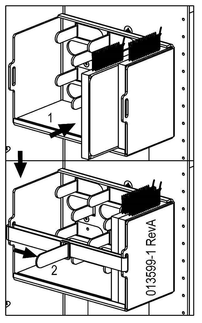
44 Cable Installation (Patch & Splice Versions Only) Cable Splicing Determine which feed-through hole will be used to install the feeder cable. If the corresponding feed-through plate already has a cable installed, you will need to loosen the compression fitting securing the cable to the plate. This will allow the plate to slide along the preinstalled cable (Fig 12). Figure 12 Remove the six mounting screws that are holding the plate to the floor of the rear of the cabinet, saving the mounting screws. Select the compression fitting that most nearly fits the cable to be installed. The fittings are included in the ship-along hardware. Loosen, or if needed, remove the dome nut on the compression fitting to allow the cable to fit through the internal sealing ring (Fig. 13). Figure 13 44


45 NOTE: The sealing ring inserts come in different sizes and colors, and can be interchanged to meet the cable size. Make sure compression fittings are tight and secure. Locate the end of the cable to be spliced into the cabinet. Feed this end through the locknut, the feedthrough plate, the compression fitting and finally the dome nut. Thread the locknut onto the fitting, being careful to avoid crossing the threads and tighten firmly against the feed-through plate. Reinstall the feed-through plate by securing it to the floor of the cabinet using the original six mounting screws. Determine the correct amount of outer jacket to remove from the cable by referencing the splicing section of this manual. Pull enough of the cable through the compression fitting to allow access to the splicing area. Install the distribution cable as described in the cable installation section. Remove 15 feet of the outer jacket. Group the buffer tubes to be spliced and fully insert them into one of the mesh sleeves enclosed in the ship along hardware. This will help to control the bundle while routing and storing. Start marking the buffer tubes 10 feet from the outer jacket and staggering the marks 1" longer for each buffer tube. Remove all Clearview Cassettes from panel that are to be spliced (if required). SEE THE SPLICING MANUAL FOR SPLICING IN THE CLEARVIEW CASSETTE. After splicing is complete, stack the cassettes and tie them together using cable ties for easy installation (Fig. 34). Figure 34 45


.")
46 Route the grouped buffer tubes first over the top radius limiter. Continue routing the grouped buffer tubes down and around the bottom radius limiter. Finish routing the grouped buffer tubes back up and around the top radius limiter. After routing the buffer tubes, install the cassette into the bulkhead in the appropriate port locations from the rear of the cabinet and tighten fastener screws (Fig. 37). NOTE: Re-tighten the seal-con fitting nut, being sure not to damage the threads. 46

47 288 PON Routing (Rear of Cabinet) The suggested cable routing for feeder and distribution cables is in the rear of the cabinet. NOTE: Cables should enter cassettes on side closest to cable management not crossed over. 47

48 576 PON Routing (Rear of Cabinet) Suggested cable routing for feeder and distribution cables in the rear of the cabinet. NOTE: Cables should enter cassettes on side closest to cable management not crossed over. 48

 using the included hardware.")
49 288/432 PON and 432 Cross-Connect Installation of Pole Mount 1. Locate and install using the included hardware, a Hoist Plate to the top of the cabinet. 2. Place the plate on the side of the cabinet that will be closest to the pole. NOTE: A second hoist plate is included for use if the cabinet will be raised with a hoist. Hoist Plate 3. Locate the toothed bracket that has mounting holes in the flange and mount it to the base (below the previously installed Hoist Plate) using the included hardware. Toothed Bracket 4. Determine the top height of the cabinet. Drill a 5/8 hole 8 inches below the anticipated height of the cabinet, all the way through the pole. 49

 should be used on nuts to prevent loosening of nuts. Make sure the thread rod/nut does not exceed the top bend in bracket or it will interfere with cabinet.")
50 5. Mount the loose toothed bracket to the pole using threaded rod, washers and nuts on either side of the pole. Rod length will depend on the diameter of the pole. It is suggested to add 3 to the diameter of pole for rod length. NOTE: Clearfield does not recommend using lag bolts to mount cabinet to pole. Clearfield recommends using hardware with a minimum of 5/8" diameter. Care should be taken to avoid over-tightening and deforming the hoist plate. Lock tight (red) should be used on nuts to prevent loosening of nuts. Make sure the thread rod/nut does not exceed the top bend in bracket or it will interfere with cabinet. Threaded rod Pole Mounting 6. Lower the cabinet onto the pole mounted toothed bracket until the Hoist Plate is over the flange of the toothed bracket. Hoist Plate 50


51 7. Level cabinet and drill 5/8 hole through lower bracket and pole, and install 5/8 rod, washers and nuts. Toothed Bracket NOTE: Care should be taken to avoid over-tightening and deforming the hoist plate. 8. Cabinet fully mounted. Pole Mounting 51


52 FieldSmart FSC Pole Mount Under Plate Kit 1. After cabinet has been mounted on pole, the optional Pole Mount Under Plate Kit may be installed. 2. The kit comes with two plates with stenciled templates for multiple sizes of conduit. The standard knock out is for a 2 conduit. If larger conduit is being used, cut the plates to the appropriate size. 3. After plates have been prepared for correct conduit, install one side of the plate onto the bottom of the cabinet. 4. Install conduit and cable. Secure conduit with cable clamp provided in kit on inside/top of the installed plate. 5. Install remaining plate locking the conduit in place. 6. RTV or other silicone type sealing may be used if needed to seal opening. 52


. 2. Draw arrows showing the 3 dimples 3. Carefully drill a 1.365 inch hole using the dimple as a centering point 4.")
53 Optional Top Cable Entrance Ports If this option is used the CABINET is typically drilled at the factory and sent to the customer with watertight plugs installed to maintain cabinet s environmental integrity. If additional cables need to be added to the top entrance holes: 1. Remove wing nut and washer from inside of cabinet 2. Carefully remove the grey sealing plug from hole 3. Install 1 NPT sealing plug and correct size cable grommet tighten to cabinet 4. Install cable through grommet/plug and into cabinet 5. NOTE MIDSPANNING of cable cannot be done using the top entry ports If the cabinet does not have factory drilled holes, the following can be done to field install to the cable entrance ports: 1. Locate the dimples on the top of the cabinet (there are 6 on the 288 PON, 432 PON and 432 Cross-Connect Cabinets - these are the cabinets that can be pole mounted). 2. Draw arrows showing the 3 dimples 3. Carefully drill a inch hole using the dimple as a centering point 4. Debur hole, being careful not to scratch/damage painted surface 5. Install 1 NPT sealing plug into hole and tighten 6. Install cable as mentioned above 7. NOTE: MIDSPANNING of cable cannot be done using the top entry ports 53
 7. Cable Clamp Shells a. 1\" (003716) b. 3/4\" (003717) c. 1/2\" (003711) 8. Clamp Mounting Screw (001527) 9. Kit Mounting Bolts (009098) 1. 4. 10. 2. 11. 3. 12. 5. 6. 7. 8. 9. 54")
54 Accessories Mid-Span, Opening Feed-through Plate Kit 1. Grommet Tape (003042) 2. Bottom Plate B (009598) 3. Clamping Bracket (009599) 4. Feed through Plate A (009597) 5. Foam Sealing Plug (XXXXXX) 6. Foam Gasket (009157) 7. Cable Clamp Shells a. 1" (003716) b. 3/4" (003717) c. 1/2" (003711) 8. Clamp Mounting Screw (001527) 9. Kit Mounting Bolts (009098)


55 Mid-Span Cable Prepping Prep the cable according to the instructions provided with the cabinet. NOTE: This kit will enable the cable to be prepped using either a midspan opening or the end of the cable. Locate the green clamp shells and corresponding 1/4-20 mounting screws from the ship-along hardware. The clamp shells are used in same-size pairs. Avoid using a clamp that is too small and does not easily close around the cable. Use the next larger clamp and grommet tape. Grommet tape should be applied to the green clamp shell prior to installation. Locate the height that is required to install the cable and mark the cable jacket where the cable passes through the floor of the cabinet. Be sure to leave at least 3" to 4" above the cabinet floor. Wrap grommet tape around the cable at the mark, until you have an overall outside diameter of 1 3/4". 55


56 Now the cable can be slid into the slot required, in feed through plate A. Feed through plate B can then be slid onto the cable followed by the cable clamp bracket. All four pieces can now be pinned together in the air by using 4 of the kit mounting bolts. Attach the kit to the base of the cabinet using the 6 kit mounting bolts and tightening them evenly to avoid warping the plates. Attach the cable clamps to the bracket using the clamp mounting screws. The unused holes can be plugged with the included foam plugs. The plugs can be installed by squeezing and compressing the foam until they are able to fit into the hole. The foam will then expand to seal the hole. 56
FieldSmart Fiber Distribution System (FDS)
") FieldSmart Fiber Distribution System (FDS) Installation Manual Patch Panels Optical Component Chassis (OCC) Miscellaneous 5480 Nathan Lane Plymouth, MN 55442 Part #: 008830 Rev: C Updated: 5.2011 Direct:
FieldSmart Fiber Distribution System (FDS) Installation Manual Patch Panels Optical Component Chassis (OCC) Miscellaneous 5480 Nathan Lane Plymouth, MN 55442 Part #: 008830 Rev: C Updated: 5.2011 Direct:
CraftSmart Fiber Protection Vaults (FPV)
") Fiber Protection s (FPV) Application CraftSmart Fiber Protection s (FPV) can be used to securely mount a FieldSmart Fiber Scalability Center (FSC) 288, 432, 57 or 1,152 port cabinet, a 432 or 84 port cross-connect
Fiber Protection s (FPV) Application CraftSmart Fiber Protection s (FPV) can be used to securely mount a FieldSmart Fiber Scalability Center (FSC) 288, 432, 57 or 1,152 port cabinet, a 432 or 84 port cross-connect
FieldSmart Fiber Delivery Point (FDP) Installation Manual
 Installation Manual") FieldSmart Fiber Delivery Point (FDP) Installation Manual Indoor 36, 96, 144 Port Wall Box Outdoor 24 or 48 Port Wall Box Indoor/Outdoor SCD Wall Box Pedestals Small Count Delivery (SCD) Case CraftSmart
FieldSmart Fiber Delivery Point (FDP) Installation Manual Indoor 36, 96, 144 Port Wall Box Outdoor 24 or 48 Port Wall Box Indoor/Outdoor SCD Wall Box Pedestals Small Count Delivery (SCD) Case CraftSmart
General Introduction Product Description Specifications Outdoor FDH-288 Series Dimensions... 3
 Installation Guide FDH-288 Series Fiber Distribution Hub (FDH) Table of Contents General... 1 1. Introduction... 2 1.1 Product Description... 2 1.2 Specifications... 3 1.3 Outdoor FDH-288 Series Dimensions...
Assembly Instructions
 InTandem Table System November 20 InTandem Table System - Worksurface #4 x/" 4 wood screw power beam Tools Provided T-0 Extended Torx Driver T-25 Torx Driver Additional Tools Required Soft protective
Fiber Splice Box (FSB-D) Installation Instructions
 Installation Instructions") Fiber Splice Box (FSB-D) Installation Instructions Table of Contents General Product Information... 1.0 Safety Precautions... 2.0 Tools Required... 3.0 Package Contents... 4.0 Installing the Product Unpacking...
Fiber Splice Box (FSB-D) Installation Instructions Table of Contents General Product Information... 1.0 Safety Precautions... 2.0 Tools Required... 3.0 Package Contents... 4.0 Installing the Product Unpacking...
Optical Cable Entry Facility (OCEF) Installation Instructions
 Installation Instructions") Instruction Sheet 860380690 Uniprise Solutions Optical Cable Entry Facility (OCEF) Installation Instructions General The Optical Cable Entry Facility (OCEF) cabinets store optical fiber splices between
Instruction Sheet 860380690 Uniprise Solutions Optical Cable Entry Facility (OCEF) Installation Instructions General The Optical Cable Entry Facility (OCEF) cabinets store optical fiber splices between
Introduction to CraftSmart Physical Fiber Protection
 Introduction to Physical Fiber Protection The Clearfield CraftSmart product line provides physical fiber protection for Clearview products. It completes and delivers a turn-key passive solution from the
Lange Crank Hoist-a-top Assembly Instructions
 Lange Crank Hoist-a-top Assembly Instructions Installation Time: 1-4 Hours depending on skill level Tools Required: Cordless Drill Level Stud Finder Ratcheting wrench 9/16 socket or wrench 11/16 socket
Preference Collection and Treatment Console INSTALLATION GUIDE
 Preference Collection 5580.69 and 5580.96 Treatment Console INSTALLATION GUIDE WARNING Failure to install the 5580 as described in this installation guide may cause the unit to collapse, resulting in serious
READ BEFORE INSTALLING UNIT INSTALLATION WARNINGS AND CAUTION
 edium + Heavy duty READ BEFORE INSTALLING UNIT INSTALLATION WARNINGS AND CAUTION Carefully read the installation manual before beginning. Pay attention to danger and safety notices. be exposed: Carefully
Installation Instructions
 edium + Heavy duty READ BEFORE INSTALLING UNIT Preliminary instructions: 1. Check window opening size: the mounting parts furnished with this air conditioner are made to install in a wooden sill double-hung
CM340B STOP READ ALL OF THE FOLLOWING INSTRUCTIONS BEFORE REMOVING SERVER CABINET FROM SKID
 CM340B STOP READ ALL OF THE FOLLOWING INSTRUCTIONS BEFORE REMOVING SERVER CABINET FROM SKID NET-ACCESS Server Cabinets Panduit Corp. 2010 INSTRUCTIONS CM340B CS1 (1) Base Cabinet (2) Solid Side Panels
INSTALLATION INSTRUCTIONS Small Flat Panel Mounts Model: F-Series
 INSTALLATION INSTRUCTIONS Small Flat Panel Mounts Model: F-Series This Instruction Manual covers most of the F-Series wall and desk mounts, as well as selected F-Series pole mounts. NOTE: Some F-Series
KWIK-KIT KK-S INSTALLATION INSTRUCTION PACKAGE
 KWIK-KIT KK-S-120-02 INSTALLATION INSTRUCTION PACKAGE INSTALLATION INSTRUCTIONS HAVIS KWIK-KIT KK-S-120-02 2002-2007 DODGE/FREIGHTLINER SPRINTER VAN PLEASE READ COMPLETE INSTRUCTIONS PRIOR TO INSTALLATION
Installation Instructions
 For Medium (15-18.5K) + Heavy duty (22-28.5K) Air Conditioner READ BEFORE INSTALLING UNIT To avoid risk of personal injury, property damage, or product damage due to the weight of this device and sharp
Preference Collection 5580 Treatment Console INSTALLATION GUIDE
 Preference Collection 5580 Treatment Console INSTALLATION GUIDE 0 WARNING Failure to install the 5580 as described in this installation guide may cause the unit to collapse, resulting in serious injury
Connect Transit Shelter
 Tools Required *denotes special tools required Connect Shelter, 8ft Connect Shelter, 12ft *Soft, non abrasive protective surface such as a furniture blanket *Source of compressed air (for thorough dust
PORTABLE ADJUSTABLE BASKETBALL SYSTEM
 Instruction Manual PORTABLE ADJUSTABLE BASKETBALL SYSTEM P A R T S L I S T 5 1/2 and 8 safe play clearance Item Qty Description Item Qty Description A 1 Portable Base Assembly M 4 1/2 Lock Nut B 2 Front
MAKO TM CASH DISPENSER
 MAKO TM CASH DISPENSER PEDESTAL INSTALLATION GUIDE VERSION 2.0 TDN 0702-000 2/99 CORPORATE HEADQUARTERS: RMA (RETURN MATERIAL AUTHORIZATION) RETURN ADDRESS: 522 E. Railroad Street 2405 B Street Long Beach,
INSTALLATION INSTRUCTIONS
 INSTALLATION INSTRUCTIONS HIGH PRESSUE LAMINATE (HPL) TOILET PARTITIONS 1030 TrimLineSeries 1040 DesignerSeries Includes continuous hardware option.65. IMPORTANT: Storage and Handling Information on last
PRODUCT: LOKI INSTALLATION INSTRUCTIONS. Product is covered by U.S. patents. For more information visit
 R INSTALLATION INSTRUCTIONS PRODUCT: LOKI CONFIGURATION: SINGLE DOOR MOUNT: GLASS MOUNT Product is covered by U.S. patents. For more information visit www.krownlab.com . TOOLS + MATERIALS REQUIRED TOOLS
COYOTE Terminal Closure (Single Chamber) Hermetically Sealed With Hardened Adapters
 Hermetically Sealed With Hardened Adapters") JUNE 2006 COYOTE Terminal Closure (Single Chamber) Hermetically Sealed With Hardened Adapters Be sure to read and completely understand this procedure before applying product. Be sure to select the proper
JUNE 2006 COYOTE Terminal Closure (Single Chamber) Hermetically Sealed With Hardened Adapters Be sure to read and completely understand this procedure before applying product. Be sure to select the proper
MPA-9000 Universal Ceiling Projector Mount Kit
 I N S T R U C T I O N M A N U A L Universal Ceiling Projector Mount Kit The Universal Ceiling Projector Mount provides a unique, simplified method of ceiling mounting your inverted projector. This low
Mighty Mo GX Series Cabinet Installation Guide. OR Rev /11
 Mighty Mo GX Series Cabinet Installation Guide OR-71601787 Safety and Warning ATTENTION The exclamation point within an equilateral triangle is intended to alert the user to the presence of important operating
INSTALLATION INSTRUCTIONS LARGE FLAT PANEL IN WALL ENCLOSURE Model: PAC-500
 INSTALLATION INSTRUCTIONS LARGE FLAT PANEL IN WALL ENCLOSURE Model: PAC-500 Specifications: Designed for in-wall installation spanning a minimum of 3 wood studs, 16" on center. Accomodates MWR, PWR and
Installation Instructions for Vista Air Vertically Folding Walls
 Installation Instructions for Vista Air Vertically Folding Walls Use these instructions in conjunction with your shop drawings to see the specifics that are particular to the model you are installing.
CONTENTS TOOL LIST U P S I D E I N N O V A T I O N S, L L C RAMP AND STEP SYSTEM ASSEMBLY INSTRUCTIONS. Revised: June 2013
 U P S I D E I N N O V A T I O N S, L L C RAMP AND STEP SYSTEM ASSEMBLY INSTRUCTIONS TOOL LIST Required Tools: - Reciprocating Saw with Metal Cutting Blade - Drill - 7/16 Drill Bit for Metal Drilling -
Frameless Inline Door With Return QCI5263
 INSTALLATION INSTRUCTIONS Frameless Inline Door With Return QCI5263 WALL MOUNT HINGES FRAMELESS DOOR / PANEL / RETURN PANEL QCI5263 REV. 0 Page 1 Certified 06/17/2016 Parts List with wall mount hinges
Parts list continues on Page 2 HOUSE PARTS PACKED IN HOUSE BOX PARTS IN SMALL PLASTIC BAG (HARDWARE) POST PARTS PACKED IN THIS BOX (LARGE PLASTIC BAG)
 POST PARTS PACKED IN THIS BOX (LARGE PLASTIC BAG)") Form 05-07 Instructions and Parts List MSS- Martin Safety System NOTES: () A complete system is packed in two boxes post box and house box. House box contains hardware for both post and house assembly.
Form 05-07 Instructions and Parts List MSS- Martin Safety System NOTES: () A complete system is packed in two boxes post box and house box. House box contains hardware for both post and house assembly.
D. Drill Bolt Holes Through Topper Shell and Bed Rails
 A. Check Mounting Kit Check to make sure that all of the following items are included in the mounting kit. Call 515-272-4372 if you need to obtain a part from BrandFX. Double-stick tape (1 roll) White
1. VERIFY ALL COMPONENTS
 R INSTALLATION INSTRUCTIONS RAGNAR+ODEN FACE MOUNT, BYPASSING. VERIFY ALL COMPONENTS BASE KIT Track stand-offs Front trolley kit * Rear trolley kit * Allen keys Track fastener kit - wood - Bottom guide
OVERVIEW You are installing 2 Major components: SITE PREP Remove organics
 OVERVIEW You are installing 2 Major components: Dimensionally stable exterior frame with pre-drilled thread-bar holes. High yield thread-bar in a predetermined grid pattern (slab) and a heavy concentration
INSTALLATION INSTRUCTIONS HEAVY DUTY TILT WALL MOUNT Model: PPH-2000
 INSTALLATION INSTRUCTIONS HEAVY DUTY TILT WALL MOUNT Model: PPH-2000 Specifications: Accomodates Akira and Orion 84" displays without interface bracket; accomodates other large flat panel displays with
IMPORTANT: installation. FLOOR ANCHORED CEILING HUNG OVERHEAD BRACED FLOOR-TO- CEILING ANCHORED
 INSTALLATION INSTRUCTIONS MAXIMUM PRIVACY COMPACT LAMINATE TOILET PARTITIONS 2080 DuraLineSeries 2180 DuraLineSeries Class-A Fire Rated Includes Institutional Hardware Option.67 IMPORTANT: Storage and
MantelMount. TM1A Installation Instructions IMPORTANT SAFETY INSTRUCTIONS - SAVE THESE INSTRUCTIONS
 MantelMount TMA Installation Instructions IMPORTANT SAFETY INSTRUCTIONS - SAVE THESE INSTRUCTIONS TM Thank you for choosing the MantelMount television wall mount. Please read this entire manual before
STOP. V00029AC Rev. 04 READ ALL OF THE FOLLOWING INSTRUCTIONS BEFORE REMOVING CABINET FROM SKID TOOL LIST. NET-ACCESS S-Type Network Cabinets
 Rev. 04 STOP READ ALL OF THE FOLLOWING INSTRUCTIONS BEFORE REMOVING CABINET FROM SKID NET-ACCESS S-Type Network Cabinets -Phillips screwdriver -Flatblade screwdriver -22mm socket wrench -15mm socket wrench
Assembly Instructions 10 X 10 Aluminum Frame Building
 Assembly Instructions 10 X 10 Aluminum Frame Building 27 97 9 8 47 36 74 52 10 10 X 10 Square Building W/ Dome Includes: The Steel Entry Door with a Dead Bolt Lock assembly and Aluminum Door Frame. Metal
HOUSE PARTS PACKED IN HOUSE BOX PARTS IN PLASTIC BAG (HARDWARE) PARTS IN SMALL PLASTIC BAG (FLOOR CLIPS) PARTS PACKED IN BUNDLE
 PARTS IN SMALL PLASTIC BAG (FLOOR CLIPS) PARTS PACKED IN BUNDLE") Check parts against this list before starting assembly. Refer to illustrations on pages 6 and 7 to view house parts. If any shortages are found, refer to Packing Slip for claim instructions. Item 3 5 6
Check parts against this list before starting assembly. Refer to illustrations on pages 6 and 7 to view house parts. If any shortages are found, refer to Packing Slip for claim instructions. Item 3 5 6
INS A KSCR INSTALLATION INSTRUCTIONS STANDARD PROCEDURE. 1. Unpacking the KSCR Splicing the KSCR (If Required)...
...") INS-88.500-0A KSCR INSTALLATION INSTRUCTIONS STANDARD PROCEDURE 1. Unpacking the KSCR... 2 2. Splicing the KSCR (If Required)... 4 3. Assemble Curb and Rail Corners... 5 4. Install Cross Bracing (If Required)...
INS-88.500-0A KSCR INSTALLATION INSTRUCTIONS STANDARD PROCEDURE 1. Unpacking the KSCR... 2 2. Splicing the KSCR (If Required)... 4 3. Assemble Curb and Rail Corners... 5 4. Install Cross Bracing (If Required)...
INSTALLATION INSTRUCTIONS
 INSTALLATION INSTRUCTIONS SOLID PHENOLIC TOILET PARTITIONS 1080 DuraLineSeries Class-A Fire Rated Includes Institutional Hardware Option.67 IMPORTANT: Storage and Handling Information on last page. Review
MC CHANGER CABINET INSTALLATION INSTRUCTIONS
 8M00356 REV. 10 www.standardchange.com 1-800-968-6955 Technical Phone Support is from 8:00AM to 7:30PM E.S.T., Monday-Friday Walk-in Service is from 8:00AM to 4:30PM E.S.T., Monday-Friday Parts Department
BBF Series Blower Base Frame Assembly Instructions Rev.: BFA-9105
 BBF Series Blower Base Frame Assembly Instructions Rev.: BFA-9105 These assembly instructions are to be used as a general reference guide to facilitate assembly. Please consult the blower, bushing, sheave,
INSTRUCTION SHEET. PIECE INVENTORY - MOBILE BASES Refer to the diagram for part identification.
 INSTRUCTION SHEET D2260 HEAVY-DUTY MINI-MOBILE BASE D2057 HEAVY-DUTY MOBILE BASE D2058 SUPER HEAVY-DUTY MOBILE BASE D2259 EXTENSION KIT FOR D2260/D2057 D2246 EXTENSION RAIL KIT FOR D2058 This Shop Fox
Customer Notice: Congratulations again on your SawStop purchase, and thank you! -SawStop Tualatin, OR
 Customer Notice: Congratulations on the purchase of this Sliding Crosscut Attachment. As the owner of a SawStop saw, you are familiar with our high standards for quality, fit and finish. Different from
YUKON PATIO COVER INSTALLATION INSTRUCTIONS
 YUKON PATIO COVER INSTALLATION INSTRUCTIONS Before You Begin: Consult your local building department for any required permits You may be required to obtain a building permit for this structure. Contact
NOTE: Top section pole (Q) is packed INSIDE bottom section pole (S)
 is packed INSIDE bottom section pole (S)") Form 0905-0 Instructions and Parts List TM- Mini Castle (modified) MARTIN SAFETY SYSTEM NOTES: () A complete system is packed in two boxes post box and house box. House box contains hardware for both post
Form 0905-0 Instructions and Parts List TM- Mini Castle (modified) MARTIN SAFETY SYSTEM NOTES: () A complete system is packed in two boxes post box and house box. House box contains hardware for both post
WPS crew Doors Installation instructions
 WPS-132-133 crew Doors Installation instructions ORDER OF INSTALLATION FOR A COMPLETE ENCLOSURE OF A CREW WPS (Weather Protection System) IS AS FOLLOWS: 1. Heater 2. Rear Thresholds - Right Hand & Left
Frameless Inline Door QCI5254
 INSTALLATION INSTRUCTIONS Frameless Inline Door QCI5254 FRAMELESS DOOR / PANEL QCI5254 REV. 0 Page 1 Cer fied 06/16/2016 Parts List with wall mount hinges *Quanes may vary QCI5254 REV. 0 Page 2 Cer fied
GroundControl. Follow instructions contained in this manual. Incorrect installation could result in serious injury or damage to property.
 GroundControl TM use supplied hardware Use only hardware supplied in your GroundControl kit or supplied by an authorized YAKIMA dealer. Use of unauthorized parts in the GroundControl system could result
1. TOOLS + MATERIALS REQUIRED
 R INSTALLATION INSTRUCTIONS PRODUCT: BALDUR + ODEN CONFIGURATION: BI-PARTING DOOR MOUNT: TOP MOUNT Product is covered by U.S. patents. For more information visit www.krownlab.com. TOOLS + MATERIALS REQUIRED
CFO-BAS-X-801 General Description and Installation
 CFO-BAS-X-801 General Description and Installation LTCFO-BAS-X-801 9 th Printing, February 28, 2018 1. GENERAL INTRODUCTION... 1 1.1. Document Purpose... 1 1.2. Product Purpose... 1 1.3. Product Mounting
Innovative Infrastructure for Electric and Hybrid Vehicles PEDESTAL EXTENSION KIT INSTALLATION GUIDE
 Innovative Infrastructure for Electric and Hybrid Vehicles PEDESTAL EXTENSION KIT INSTALLATION GUIDE PLEASE NOTE: This installation guide includes the latest information at the time of printing. ClipperCreek,
INSTALLATION INSTRUCTIONS
 INSTALLATION INSTRUCTIONS MAXIMUM PRIVACY HIGH PRESSURE LAMINATE (HPL) TOILET PARTITIONS 2030 TrimLineSeries 2040 DesignerSeries IMPORTANT: Storage and Handling Information on last page. Review these instructions
600G2 Internal Sliding Adapter Panel Shelf Instructions
 Instruction Sheet 860391986 Issue 6, February 2013 SYSTIMAX Solutions 600G2 Internal Sliding Adapter Panel Shelf Instructions General The SYSTIMAX 600G2 adapter panel shelf is 19-inch wide x 1.75-inch
INSTALLATION INSTRUCTIONS
 INSTALLATION INSTRUCTIONS SELF LEVELING RADAR ANTENNA MOUNT MODEL 400G QUESTUS MARINE, INC. PO BOX 9 MARBLEHEAD, MA 01945 1-800-RADAR66 TEL 781.639.1900 FAX 781.639.1905 www.questusmarine.com INSTALLATION
GrowSpan Series 500 Roll-Up Ends
 GrowSpan Series 500 Roll-Up Ends Photo may show a different but similar model. Doorframe materials are not included. 2016 Growers Supply All Rights Reserved. Reproduction is prohibited without permission.
Hardened Structures Hardened Shelters, LLC. Explosion Resistant Pre-hung Sealed Blast Door
 Hardened Structures Hardened Shelters, LLC Explosion Resistant Pre-hung Sealed Blast Door Drawing number: ASR-50-BD Revision: E Date: December 8, 2008 Table of Contents Contact Information... 3 Description...
TS-20KD-1010 LOW PROFILE CARGO SCALE INSTALLATION GUIDE
 TS-20KD-1010 LOW PROFILE CARGO SCALE INSTALLATION GUIDE Triner Scale & Mfg. Co., Inc. 8411 Hacks Cross Rd. Olive Branch, MS 38654 Phone: 800-238-0152 Fax: 662-809-2386 Description The Triner Scale Model
Installation and Assembly - Universal Articulating Swivel Double-Arm for 42" - 60" Plasma Screens
 Installation and Assembly - Universal Articulating Swivel Double-Arm for 42" - 60" Plasma Screens Models: PLAV 70-UNL, PLAV 70-UNL-S PLAV 70-UNLP, PLAV 70-UNLP-S R This product is UL Listed. It must be
INSTALLATION & OWNER S MANUAL
 Rev. O p. 1 of 16 INSTALLATION & OWNER S MANUAL V4213 BALL CAGE KIT INSTALLATION & OWNER S MANUAL The contents of this envelope are the property of the owner. Be sure to leave with the owner when installation
18000 HDL FOUR POST LIFT LB CAPACITY INSTALLATION AND OWNER'S MANUAL
 18000 HDL FOUR POST LIFT 18000 LB CAPACITY INSTALLATION AND OWNER'S MANUAL WARNING! Do not raise a vehicle unless the front stops are in place, the parking brake is set, and the wheels are chocked. Stay
Kiosk Solution W1000. Installation and Assembly Instructions July 2015 Edition
 Kiosk Solution W1000 Installation and Assembly Instructions July 2015 Edition All product names mentioned in this document are the trademarks, brands or registered trademarks of their respective owner.
GlideRite Retractable Cover System For HotSpring & Tiger River Spas (except Classic & pre-2000 Landmark Spas)
") List of Contents Quantity Description 12 #10 x 1 ½ Flat Head Phillips Screw (see pg. 2) 2 #10 x ½ Pan Head Phillips Screw (see pg. 2) 8 ¼ x 2 ½ Lag Bolt (see pg. 2) 7 ¼ 20 x 5 / 8 Hex Head Bolt (see pg.
List of Contents Quantity Description 12 #10 x 1 ½ Flat Head Phillips Screw (see pg. 2) 2 #10 x ½ Pan Head Phillips Screw (see pg. 2) 8 ¼ x 2 ½ Lag Bolt (see pg. 2) 7 ¼ 20 x 5 / 8 Hex Head Bolt (see pg.
INSTALLATION INSTRUCTIONS
 INSTALLATION INSTRUCTIONS HIGH PRESSUE LAMINATE (HPL) TOILET PARTITIONS 1030 TrimLineSeries 1040 DesignerSeries Includes continuous hardware option.65. IMPORTANT: Storage and Handling Information on last
General Prisoner Transport Install Instructions PT-2-INST
 General Prisoner Transport Install Instructions PT-2-INST 50 or 60 high x 80, 100 & 120 inch long / Double Compartment Inserts Also refer to PT-A-3XX instructions for vehicle specific mounting measurements
======================================================================================== ( DR / DR) JK WRANGLER MOD RACK
 JK WRANGLER MOD RACK") (10984 4DR / 10982 2DR) JK WRANGLER MOD RACK INSTALLATION SHEET Important Notes: Some brands of windshield light brackets and snorkels may not be compatible with the 10984 MOD Rack System. Body lifts are
(10984 4DR / 10982 2DR) JK WRANGLER MOD RACK INSTALLATION SHEET Important Notes: Some brands of windshield light brackets and snorkels may not be compatible with the 10984 MOD Rack System. Body lifts are
M2 Antenna Systems, Inc. Model No: 20M6-125
 M2 Antenna Systems, Inc. Model No: 20M6-125 SPECIFICATIONS: Model... 20M6-125 Frequency Range... 14.0 14.350 MHz *Gain, (FS) / Over gnd... 11.19dBi / 16.6dBi @70 Front to back... 25 db Typical Beamwidth...
INSTALLATION INSTRUCTIONS
 INSTALLATION INSTRUCTIONS COMPACT LAMINATE TOILET PARTITIONS 1080 DuraLineSeries 1180 DuraLineSeries Class-A Fire Rated Includes Institutional Hardware Option.67 IMPORTANT: Storage and Handling Information
Installation Guide Simplicity Alfresco. V1.9 Lu070318
 0333 305 5272 www.canoports.co.uk Installation Guide Simplicity Alfresco V1.9 Lu070318 Tools Required Below is a list of tools that you will require to install your the Simplicity Alfresco System. Cordless
Sliding Crosscut Table installation guide
 Sliding Crosscut Table installation guide model tsa-sa48 A Note About Color Variations Among Anodized Aluminum Components Congratulations on the purchase of this SawStop Sliding Crosscut Table. We at SawStop
OB1U INSTALLATION INSTRUCTIONS. Interactive Flat Panel Over White Board Mount
 INSTALLATION INSTRUCTIONS Interactive Flat Panel Over White Board Mount Spanish Product Description German Product Description Portuguese Product Description Italian Product Description Dutch Product Description
installation guide
 JANUS INTERNATIONAL 1 866 562 2580 w w w. j a n u s i n t l. c o m 2000 2500 3000 installation guide RIGHT DRIVE END SHOWN LH OPPOSITE LEFT TENSION END SHOWN RH OPPOSITE PUSH-UP OPERATION 2000 2500 3000
10x10 Trellis Pergola
 0x0 Trellis Pergola ASSEMBLY GUIDE Ver.-007 Table of Contents PAGE 0x0 Trellis Pergola Introduction & Overview...................................................... Pergola Materials Overview..............................................................
OXYGEN INSTALLATION. Revision date
 12345 1 Hardware List 12345 Flat head wood screw #9 x 7/8 long with #2 Phillips drive, silver Used to attach surfaces and end panels Hex set screw ½-13 x 2 long with 1/4 hex drive, black Used on Legs Hex
Assembly Instructions. Important!
 Play Action Spiral Tube Slide Assembly Instructions Important! Intended for residential use by children ages 2 to 10, only on properly installed PlayStar playsets. Before use refer to complete safety guidelines
GlideRite Retractable Cover System For Hot Spot Spas (SE & SLX only)
") List of Contents Quantity Description 12 #10 x 1 ½ Flat Head Phillips Screw (see pg. 2) 2 #10 x ½ Pan Head Phillips Screw (see pg. 2) 8 ¼ x 2 ½ Lag Bolt (see pg. 2) 7 ¼ 20 x 5 / 8 Hex Head Bolt (see pg.
List of Contents Quantity Description 12 #10 x 1 ½ Flat Head Phillips Screw (see pg. 2) 2 #10 x ½ Pan Head Phillips Screw (see pg. 2) 8 ¼ x 2 ½ Lag Bolt (see pg. 2) 7 ¼ 20 x 5 / 8 Hex Head Bolt (see pg.
400A 40113V, 401A 40120V, & 401AL 40120VL ALUMINUM VERTICAL 4000 LB LIFT INCLUDES SCREW LEG ASSEMBLY INSTRUCTIONS
 12/11/07 PAGE 1 OF 12 400A 40113V, 401A 40120V, & 401AL 40120VL ALUMINUM VERTICAL 4000 LB LIFT INCLUDES SCREW LEG ASSEMBLY INSTRUCTIONS Thank you for purchasing our product! *Please read these instructions
MAKO EC EXTENDED CABINET
 MAKO EC EXTENDED CABINET INSTALLATION GUIDE VERSION 2.0 TDN 0702-00033 03/0 CORPORATE HEADQUARTERS: RMA (RETURN MATERIAL AUTHORIZATION) RETURN ADDRESS: 522 E. Railroad Street 2405 B Street Long Beach,
STELLA AUTO SIDECAR INSTALL INSTRUCTIONS
 STELLA AUTO SIDECAR INSTALL INSTRUCTIONS Open crate and inspect sidecar Remove cardboard box from inside the sidecar Remove all hardware holding the sidecar to the crate Remove sidecar from crate Remove
INSTALLATION INSTRUCTIONS FOR FRONT CASTING DECK RAIL Ranger
 INSTALLATION INSTRUCTIONS FOR FRONT CASTING DECK RAIL Ranger TOOLS REQUIRED FOR INSTALLATION: Drill motor, (1) 5/16 inch drill bit, (1) 13/64 drill bit, (1) 3/16 inch hex wrench (1) 3/32 inch hex wrench.
CUTTING THE PIPE: BLUE DUCT Pipe can be easily cut using a Circular Saw or Reciprocal Saw. Trim all edges as necessary.
 Installation Instructions In the past it has been IMPOSSIBLE to install an air and water tight underground system. BLUE DUCT (AKDUCT ) has produced a user friendly system that will reduce the amount of
LOW-PROFILE WALLMOUNT CABINETS
 USER MANUAL RMT35X SERIES LOW-PROFILE WALLMOUNT CABINETS 24/7 AT OR VISIT BLACKBOX.COM TABLE OF CONTENTS SAFETY INFORMATION... 3 Receiving, Unpacking, and Removing the Low-Profile Wallmount Cabinet from
Stainless Steel Bench Stand
 Installation Manual Stainless Steel Bench Stand Product(s): 29600 29601 51229 2016 by Fairbanks Scales, Inc. Revision 2 02/16 All rights reserved. Amendment Record STAINLESS STEEL BENCH STAND Document
INSTALLATION INSTRUCTIONS
 INSTALLATION INSTRUCTIONS A CSW Industrials Company PJC Floor Pan Expansion Joint Covers The following instructions are very important. Read them carefully, and be sure you understand them completely before
Unequal Flange Rack Installation Instructions
 Unequal Flange Rack Installation Instructions Content Page INTRODUCTION............................................................................. 2 Revision History........................................................................
MM750 Installation Instructions
 MM750 Installation Instructions IMPORTANT SAFETY INSTRUCTIONS - SAVE THESE INSTRUCTIONS Please read this entire manual before you begin. Do not unpack any contents until you verify all requirements on
The Queen Quilter Professional Quilters Kit Frame
 The Queen Quilter Professional Quilters Kit Frame Assembly Instructions Table of Contents: Before you begin......................... Pg. 2 Wood parts............................. Pg. 3 Hardware..............................
SINCE 1922 P UBLICATION N O
 SINCE 1922 GARED SPORTS MICRO-Z SET-UP INSTRUCTIONS VERY IMPORTANT! READ INSTRUCTIONS CAREFULLY AND FOLLOW STEP BY STEP SET-UP PROCEDURE P UBLICATION N O. 5 5 1 7 5 2 9 1 6 Recommended tools and accessories.
Showpiece Cabinet Integrated Stand For 32" - 52" LCD HDTV
 Showpiece Cabinet Integrated Stand For 32" - 52" LCD HDTV Installation and Assembly Instructions 2009 Incredible Technologies Inc. Version 0109 Showpiece Cabinet Integrated Stand for 32" - 52" LCD HDTV
Frameless Door QCI5284
 Frameless Door QCI5284 F AB GLASS AND MIRROR www.fabglassandmirror.com Call: +1 888-474-2221 Fax: (614)-334-4919 Office Timing: 8:30-18:00 EST info@fabglassandmirror.com INSTALLATION INSTRUCTIONS Frameless
Senior Swing. Caution
 *740132* 740132 2800 Overhead Concealed Series 9500 Surface Applied Series Senior Swing Installation Instructions Caution LCN Senior Swing The Senior Swing Power Operator System is a low energy product
southpaw enterprises, inc.
 Store these instructions in a safe place or with the enclosed maintenance checklist In-FUN-ity Climbing System Assembly Examples This example sheet is intended to supplement the instruction sheets that
Installation Guide Contemporary Alfresco V1.3 LU
 Installation Guide Contemporary Alfresco V1.3 LU 010818 Tools Required Below is a list of tools that you will require to install you're the Contemporary Alfresco System. Cordless Drill Mastic Gun Spirit
Barn Door & Hardware Installation Guide
 Barn Door & Hardware Guide INTRODUCTION Thank you for purchasing our hardware. Our barn door and hardware will add a stunning accent to your living environment and maximize its space. This manual covers
INSTALLATION INSTRUCTION
 INSTALLATION INSTRUCTION Soild Phenolic Series contents page 1080 DuraLineSeries...2-21 1180 DuraLineSeries...2-21 2080 DuraLineSeries Maximum Privacy...22-41 2180 DuraLineSeries Maximum Privacy...22-41
Factory Assistance: Phone: Fax: Page 1
 CABLE RUNWAY ACCESSORIES Radius Drop / Stringer Drop Provides 3 bend radius Radius drop fits 6, 12 and 18 runway made from 1-1/2 x 3/8 tubing Steel construction Includes (3) cable spools, (1) bolt, (1)
Medium Flat Panel Dual Swing Arm Wall Mount JWD-V
 INSTALLATION Medium Flat Panel Dual Swing Arm Wall Mount The single swing arm wall mount is designed for mounting a medium sized flat panel display. The can swing out from, or fold against, the wall depending
HD installation guide
 JANUS INTERNATIONAL 1 866 562 2580 www.janusintl.c o m 1950 1950HD installation guide RIGHT DRIVE END SHOWN LH OPPOSITE LEFT TENSION END SHOWN RH OPPOSITE PUSH-UP OPERATION 1950 1950HD SHOWN A rolling
8x8 Spa Breeze Pergola Assembly Manual Outdoor Living Today
 8x8 Spa Breeze Pergola Assembly Manual Outdoor Living Today Revision 3. Feb 18th/2015 Note: Post Mounting Hardware is NOT included in this kit. Please confirm with your local building permit office to