D. Drill Bolt Holes Through Topper Shell and Bed Rails
|
|
|
- Luke Malone
- 6 years ago
- Views:
Transcription
1
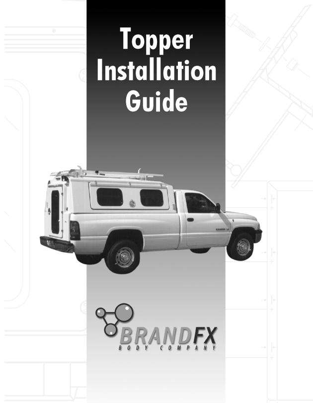
2 A. Check Mounting Kit Check to make sure that all of the following items are included in the mounting kit. Call if you need to obtain a part from BrandFX. Double-stick tape (1 roll) White silicone caulk (1 tube) Trim-Lok weather strip (9 feet) 5/16 x 3 hex head bolts (4) 5/16 x 1-1/2 hex head bolts (10) 5/16 x 1 hex head bolts (2) 5/16 nylock nuts (16) 5/16 fender washers (24) 3/16 x 1 Phillips head bolts (4) 3/16 x 3/4 flat washers (8) 3/16 nylock nuts (4) 1/4 x 5/8 self-tapping bolts (7) Galvanized thresholds (3 total: 1 left, 1 right, 1 center) B. Remove Tailgate Step B1: Remove the tailgate and, if possible, the tailgate hinges from the pickup box. Step B2: Remove if possible any protruding tailgate-latch and hinge studs from the pickup box. C. Clamp Topper Shell to Pickup Box Step C1: Position the Topper shell on the pickup box. The shell must be flush with the forward edge of the box and centered side-to-side. Step C2: Using at least two clamps per side, clamp the shell to the side rails of the box so that it will not move when you are drilling the bolt holes. D. Drill Bolt Holes Through Topper Shell and Bed Rails Step D1: You will be drilling four 3/8 holes per side, in the approximate locations shown in DIAGRAM 1. In order to determine exactly where to drill, look under each bed rail and identify and mark four unobstructed points that are as close to being equally spaced apart as possible, in order to ensure a good seal when everything is tightened down. Step D2: If you are installing the Topper on a full-size pickup you should have enough clearance to drill without unclamping and removing the Topper shell. Go ahead and drill the eight bolt holes and proceed to Step E1. If you do not have adequate clearance for drilling with the Topper shell clamped in position proceed to Step D3 below. Step D3: With the Topper shell still clamped in place, mark the hole locations identified in Step D1 directly on the Topper s flanges (if you have not already done so). Step D4: Unclamp and remove the Topper shell. Transfer the marks made in Step D3 to the bottom sides of the flanges to make drilling easier. Now drill a 3/8 hole in each of these eight locations. 1
3 Step D5: Replace the Topper shell on the pickup box, again aligning the front and sides as directed in Step C1. Clamp the shell in place and score or otherwise mark hole locations on the side rails of the pickup box through the holes drilled in the shell. Step D6: Unclamp and remove the Topper shell. Drill a 3/8 hole in each of the eight locations marked on the side rails of the pickup box in Step D5. Step D7: Replace the Topper shell on the pickup box, aligning the holes in the shell with those in the bed rails. Again clamp the shell to the side rails of the box using at least two clamps per side. DIAGRAM 1 BASIC TOPPER BASE 2
4 E. Apply Double-Stick Tape and Bolt Topper Shell to Pickup Box Step E1: You will be applying tape to the bed rails of the pickup box, not to the Topper shell. Begin by unclamping and elevating one side of the shell. Step E2: Leave the protective paper on the tape and start at the forward end of a side rail. Align the tape with the rail s inner edge and press the tape firmly into place. Then, smoothly and carefully continue peeling back the protective paper while pressing down the tape until you have covered the length of the rail. Cut the end, but DO NOT REMOVE THE PROTECTIVE PAPER FROM THE UPPER SURFACE OF THE TAPE STRIP. Topper Base (8) 5/16 x 1-1/2 Hex Head Bolt (16) 5/16 Fender Washer (8) 5/16 Nylock Nut Pickup Bed Rail DIAGRAM 2 Double-Stick Tape Step E3: Without unclamping the other side of the shell, lift the shell high enough to permit applying a strip of double-stick tape to one half of the front bed rail. Be sure to align the tape with the rail s inner edge, and do not overlap the side strip. Step E4: Now remove the protective paper from the top surfaces of the tape strips applied in Steps E3 and E4. Step E5: Carefully lower the Topper shell onto the double-stick strips and bolt it to the side rail using the hardware shown in DIAGRAM 2. (Note that you will be using one 5/16 x 1-1/2 hex head bolt, two 5/16 fender washers, and one 5/16 nylock nut for each of the four hole locations.) Step E6: Unclamp the other side of the Topper shell and repeat Steps E2 through E5 to complete the shell installation. F. Route the Wiring Harness Step F1: Run the wiring harness along the left (driver s) side of the vehicle, out the pickup box, and behind the rear bumper (see DIAGRAM 3). Step F2: Continue routing the wiring harness along or through the truck frame as necessary to complete all electrical connections in compliance with manufacturer-recommended practices. The wires are color-coded as follows: White = Ground Blue = Interior lights (requires in-line fuse) Purple = Flood lights Red = Third brake light Yellow = Strobe light 3 DIAGRAM 3
5 G. Install Rear Door Assembly Step G1: The Topper s rear door assembly is shipped loose. See DIAGRAM 4 and note the areas of the tail section that will receive the Trim-Lok weather strip. (The tail section is the lower part of the assembly that closes off the tailgate opening of the pickup box.) Apply Trim-Lok weather strip to the sides and bottom of the tail section as shown in DIAGRAM 4. DIAGRAM 4 Tail Section Step G2: Place the door assembly in its installed position on the vehicle. Lift the assembly so that the upper edges of the tail section make contact with the Trim-Lok Weather Strip base of the Topper shell. Clamp the assembly to the shell to keep it in place while drilling. Step G3: Now drill four 5/16 holes through the upper area of the door frame and the Topper shell in the locations shown in DIAGRAM 5. Bolt the frame to the shell using four 5/16 x 3 bolts. Use only one washer per bolt, and place the washer on the inside of the shell, between the shell and the nylock nut inserted from the outside in. Step G4: You will be drilling two 3/16 holes on each side of the door opening. See DIAGRAM 6 for the locations of the holes and the hardware needed to secure the tail section of the door assembly to the base of the Topper shell. Drill vertically and install the 3/16 x 1 bolts, washers, and nylock nuts as shown, in the same way you bolted the shell to the bed rails (i.e., two washers per bolt assembly). DIAGRAM 5 DIAGRAM 6 (4) 5/16 x 3 Hex Head Bolt (4) 5/16 Fender Washer (Inside Only) (4) 5/16 Nylock Nut (4) 3/16 x 1 Hex Head Bolt (2 Each Side) (8) 3/16 Flat Washer (4) 3/16 Nylock Nut 4
6 H. Install Left & Right Threshold Plates Step H1: Galvanized threshold plates secure the tail section of the door assembly to the tailgate opening. You will be installing three threshold plates: the left plate, the right plate, and the center plate. See DIAGRAM 7 and note that the left and right plates are not interchangeable. Step H2: From outside the vehicle, position the left and right threshold plates within the pickup box as shown in DIAGRAM 7. Place the 5 side of each threshold plate against the floor and the 2 side against the inside surface of the tail section. The left and right threshold plates must be at least 36 apart. Step H3: Climb inside the Topper and drill two 5/16 holes through the upright of each threshold plate and all the way through the tail section of the door assembly. Step H4: Bolt the left and right threshold plates to the tail section using the hardware shown in DIAGRAM 8. Note that 1 bolts are used for the outermost holes, and 1-1/2 bolts are used for the holes closest to the door opening. Step H5: Press the bottom of the tail section firmly against the vehicle and, maintaining pressure, drill two 7/32 holes through each threshold plate and into the pickup box floor (see locations in DIAGRAM 7). Use four 1/4 x 5/8 self-tapping bolts to secure the left and right threshold plates to the floor. DIAGRAM 7 Pickup Box Floor View looking down on Pickup bed Left Threshold Plate Center Threshold Plate Right Threshold Plate 1/4 x 5/8 Self-Tapping Bolt Locations Bumper 5
7 I. Install Center Threshold Plate Step I1: Place the center threshold plate in the position shown in DIAGRAM 7, with its lip on top of the door s rubber gasket. All three threshold plates should line up straight across on the bed side, and the door rod should slide through the access hole or slot. Step I2: Drill three 7/32 holes through the center threshold plate and into the pickup box floor, in the locations shown in DIAGRAM 7. Secure the center threshold plate to the pickup box floor using three 1/4 x 5/8 self-tapping bolts as shown in DIAGRAM 8. J. Apply White Silicone Caulk Step J1: With the white silicone caulk, seal around the top of the door frame and across the tops of the wings in the area shown in DIAGRAM 9 to complete the Topper installation. DIAGRAM 8 DIAGRAM 9 Door Assembly Tail Section Left/Right Threshold Plate White Silicone Caulk Hex Head Bolts: (2) 5/16 x 1 for Outer Holes (2) 5/16 x 1-1/2 for Inner Holes 1/4 x 5/8 Self-Tapping Bolts 6
8 Brand FX 709 Katy Road P.O. Box 545 Keller, Texas Fax:
INSTALLATION INSTRUCTIONS
 NOTE: Bolts should remain hand tight until all bolts are installed. STEP 1 Installing the door base (both sides). 1. Locate the outer, roll cage, mounting bolt (passenger side is shown in the illustration).
INSTALLATION INSTRUCTIONS PART#:17A045200MSS\17A045200MA MODULAR GRILL GUARD FOR FORD SUPER DUTY F250/F
 INSTALLATION INSTRUCTIONS PART#:17A045200MSS\17A045200MA MODULAR GRILL GUARD FOR FORD SUPER DUTY F250/F350 08-09 1 guard, center section 1 brush guard, left side 1 brush guard, right side 1 wire guard
WPS crew Doors Installation instructions
 WPS-132-133 crew Doors Installation instructions ORDER OF INSTALLATION FOR A COMPLETE ENCLOSURE OF A CREW WPS (Weather Protection System) IS AS FOLLOWS: 1. Heater 2. Rear Thresholds - Right Hand & Left
Tech Sheet. T4 Interior conversion kit how to - fitting instructions. 1. Rear seat belts. 2.
 Page 1 of 8 T4 Interior conversion kit how to - fitting instructions Thank you for purchasing our T4 interior conversion kit. This kit will enable you to convert any SWB left hand loading door T4 into
Assembly Instructions 10 X 10 Aluminum Frame Building
 Assembly Instructions 10 X 10 Aluminum Frame Building 27 97 9 8 47 36 74 52 10 10 X 10 Square Building W/ Dome Includes: The Steel Entry Door with a Dead Bolt Lock assembly and Aluminum Door Frame. Metal
INSTALLATION INSTRUCTIONS KK-K9-C12-K CHEVY IMPALA
 INSTALLATION INSTRUCTIONS KK-K9-C12-K 2000-2005 CHEVY IMPALA READ ALL INSTRUCTIONS PRIOR TO INSTALLATION TOOLS REQUIRED: Power Drill Drill bits1/4 and 5/32 7/l6 wrench and socket 15,18 and\or 19mm socket
General Prisoner Transport Install Instructions PT-2-INST
 General Prisoner Transport Install Instructions PT-2-INST 50 or 60 high x 80, 100 & 120 inch long / Double Compartment Inserts Also refer to PT-A-3XX instructions for vehicle specific mounting measurements
RH-412 STEEL DOORS INSTALLATION INSTRUCTIONS
 RH-412 STEEL DOORS INSTALLATION INSTRUCTIONS By following the steps outlined below, the assembly, installation and adjustment of the steel doors, will be a simple process. Let s start with the Driver Side.
INSTALLATION INSTRUCTIONS RH 412 STEEL DOORS
 By following the steps outlined below, the assembly, installation and adjustment of the steel doors, will be a simple process. Let s start with the Driver Side. Note: Having the hood open makes the job
INSTALLATION INSTRUCTIONS KK-K9-F14-K K9 KIT FOR FORD EXPEDITION
 INSTALLATION INSTRUCTIONS KK-K9-F14-K-32 32 K9 KIT FOR 2003-2016 FORD EXPEDITION TOOLS REQUIRED: Power Drill Drill Bit Set Standard & Metric Socket Sets Phillips Screw Driver Open End Wrench Set Wire Cutters
MM Strut Tower Brace, Cobra (MMSTB-7)
") The MM strut Tower Brace attaches to each strut tower and to the firewall. 3430 Sacramento Dr., Unit D San Luis Obispo, CA 93401 Telephone: 805/544-8748 Fax: 805/544-8645 www.maximummotorsports.com MM
The MM strut Tower Brace attaches to each strut tower and to the firewall. 3430 Sacramento Dr., Unit D San Luis Obispo, CA 93401 Telephone: 805/544-8748 Fax: 805/544-8645 www.maximummotorsports.com MM
Contractors Rack Assembly and Installation Instructions
 Part # 18601 & 16601 Contractors Rack Assembly and Installation Instructions 4751 Littlejohn St. Unit A, Baldwin Park, CA 91706 Page 1 of 12 11/13/08 Thank you for purchasing the Paramount Restyling Contractors
RBP-1215B-RX DODGE RAM QUAD CAB RX3
 RBP-1215B-RX3 2002-2017 DODGE RAM 15-3500 QUAD CAB RX3 Passenger side RX-3 Side Step Drill Template Passenger side rear Modular Bracket (6) L Support Brackets Driver side rear Modular Bracket Driver side
Installation for Full Size Polaris Ranger Crew Doors
 Installation for Full Size Polaris Ranger Crew Doors Order of Installation: Heater Doors Wiper on to Windshield Windshield Top & Back Panel Note: Most of the steps in these instructions need to be repeated
INSTALLATION INSTRUCTIONS PART#:17GT23MSS\17GT23MA MODULAR GRILL GUARD FOR CHEVY SILVERADO 1/2 TON 99-02
 INSTALLATION INSTRUCTIONS PART#:17GT23MSS\17GT23MA MODULAR GRILL GUARD FOR CHEVY SILVERADO 1/2 TON 99-02 1 guard, center section 1 brush guard, left side 1 brush guard, right side 1 wire guard insert,
INSTALLATION INSTRUCTIONS PART#:17A096400MSS\17A096400MA MODULAR GRILL GUARD FOR TOYOTA TACOMA 05-09
 INSTALLATION INSTRUCTIONS PART#:17A096400MSS\17A096400MA MODULAR GRILL GUARD FOR TOYOTA TACOMA 05-09 1 guard, center section 1 brush guard, left side 1 brush guard, right side 1 wire guard insert, left
RangerWare Fiberglass Door System Installation Instructions P/N
 Page 1 of 9 RangerWare Fiberglass Door System Installation Instructions P/N 2878016 ORDER OF INSTALLATION Note: To assure proper order, read all Accessory Installation Instructions before beginning. 1.
ASSEMBLY INSTRUCTIONS FOR MAR-K BEDSIDES AND GM FLUSH TAILGATE WITH HANDLE
 ASSEMBLY INSTRUCTIONS FOR MAR-K BEDSIDES AND 41-53 GM FLUSH TAILGATE WITH HANDLE Build the box assembly according to the MAR-K assembly instructions. When installing the tailgate and latching mechanisms
Assembly Instructions
 Unite Panel System Hinge Door July 2016 #12 x / slotted hex washer head bolt Figure 1 threshold bracket frame Detail F threshold bracket threshold bracket (installed) #12 x / slotted hex washer head bolt
Ford Pick Up Rear leaf Spring Kit Installation Instructions
 1948-1956 Ford Pick Up Rear leaf Spring Kit Installation Instructions 1-800-984-6259 www.totalcostinvolved.com Parts 48 inch leaf (2) springs (4) U-bolts 3/8-24 x l 1/4bolts (16) & nuts (2) 1/2-20 x 4
K9 KIT INSTALLATION INSTRUCTIONS CROWN VIC KK-K9-F7-K
 K9 KIT INSTALLATION INSTRUCTIONS 1998-2011 CROWN VIC KK-K9-F7-K TOOLS REQUIRED: Power Drill (Cordless preferable) Drill Bit Set Standard Wrench and Socket Set Metric Socket Set Screwdriver Set Torx Bit
Installing The Aliens Extermination Deluxe 50" Cabinet with Sintra Marquee
 Installing The Aliens Extermination Deluxe 50" Cabinet with Sintra Marquee Document Part #: 040-0262-01 This document describes how to install The Aliens Extermination Deluxe Cabinet with Sintra Marquee
VACUSEAL MODEL 200. HOT TUB PRODUCTS 233 Carrington Road Bethany CT
 VACUSEAL MODEL 200 J G F G H L HOT TUB PRODUCTS 233 Carrington Road Bethany CT 06524 860-469-2580 www.vacusealcoverlift.com www.hottubproducts.com Made in USA H K E D C I A P B 10 9 8 7 6 5 4 3 2 1 0 SPAS
IMPORTANT! Recommended Tools. 7/16 Deep socket Phillips screwdriver
 IMPORTANT! Read all instructions carefully before commencing any work. Always wear proper safety equipment. Some installation steps will require two or more installers. Recommended Tools Ratchet 10-mm
FRAME BRACKET. Doing Our Best to Provide You the Best. Ford. Page 1. BOlT TORQUE SPECIFICATIONS HJ31000,Rev 0
 2-13 HJ31000,Rev 0 Ford BOlT TORQUE SPECIFICATIONS METRIC BOlTS Size Grade Torque 8mm 8.8 23 ft/lbs. 10mm 8.8 45 ft/lbs. 12mm 8.8 78 ft/lbs. 14mm 8.8 125 ft/lbs. STANDARD BOlTS Size Grade Torque 5/16 5
Instruction Guide 4A90L
 Instruction Guide 4A90L Kargo Master Rancho Cordova, CA 95742 800-343-7486 CustomerService@KargoMaster.com DATE: *PLEASE READ ALL INSTRUCTIONS AND WARNINGS PRIOR TO ASSEMBLING, INSTALLING, AND USING THIS
INSTALLATION INSTRUCTIONS
 PACKAGE CONTENTS and PARTS LIST: INSTALLATION INSTRUCTIONS Additional copies of these instructions can also be found on our website at www.xtremegate.com in the section titled How to Install X-Treme Gate.
K9 KIT INSTALLATION INSTRUCTIONS CROWN VIC with Fire Suppression System Model KK-K9-F7-K-FS
 K9 KIT INSTALLATION INSTRUCTIONS 2005-2011 CROWN VIC with Fire Suppression System Model KK-K9-F7-K-FS TOOLS REQUIRED: Power Drill (Cordless preferable) Drill Bit Set Standard Wrench and Socket Set Metric
Pickup Box Utility Rack Package Installation (Instruction ID: )
") 017 Chevrolet Colorado Pickup - WD (VIN S) Canyon, Colorado Accessory Installation Manual N America Document ID: 3966961 Pickup Box Utility Rack Package Installation (Instruction ID:3144879) Installation
017 Chevrolet Colorado Pickup - WD (VIN S) Canyon, Colorado Accessory Installation Manual N America Document ID: 3966961 Pickup Box Utility Rack Package Installation (Instruction ID:3144879) Installation
INSTALLATION INSTRUCTIONS 3 BULL BAR 99-04, 04 "HERITAGE" F-150/250LD 2WD, 97-04, 04 "HERITAGE" 4WD WD EXPEDITION/ WD EXPEDITION PART
 INSTALLATION INSTRUCTIONS 3 BULL BAR PART #B-F1971;B-F2971 PARTS LIST: 1 Bull Bar 2 12-1.75mm x 130mm x 40mm Hex Bolts 1 Driver/Left Mounting Bracket 4 12-1.75mm x 35mm Hex Bolts 1 Passenger/Right Mounting
Medium HoneyBadger Chase Rack Installation Instructions
 PREPARATION Medium HoneyBadger Chase Rack Installation Instructions 1. Disconnect the negative terminal on the battery. Park the vehicle on level ground and set the emergency brake. 2. We recommend reading
SAFETY THIS PRODUCT IS FOR OFFROAD USE ONLY. ALL LIABILITY FOR INSTALLATION AND USE RESTS WITH THE OWNER.
 SAFETY Your safety and the safety of others is very important. In order to help you make informed decisions about safety, we have provided installation instructions and other information. These instructions
INSTALL LOAD BED TRACKS
 Universal LOAD BED TRAY & Load BArs TRBU001 / KRLBUNI1 INSTALL TIME: 2.5 Hours READ ME FIRST: Thank you for purchasing a Front Runner Slimline II Load Bed Rack or Load Bar Kit. Your Kit will contain the
======================================================================================== ( DR / DR) JK WRANGLER MOD RACK
 JK WRANGLER MOD RACK") (10984 4DR / 10982 2DR) JK WRANGLER MOD RACK INSTALLATION SHEET Important Notes: Some brands of windshield light brackets and snorkels may not be compatible with the 10984 MOD Rack System. Body lifts are
(10984 4DR / 10982 2DR) JK WRANGLER MOD RACK INSTALLATION SHEET Important Notes: Some brands of windshield light brackets and snorkels may not be compatible with the 10984 MOD Rack System. Body lifts are
INSTALLATION INSTRUCTIONS K9-C20-32 & K9-C CHEVROLET 4 DOOR TAHOE, GMC YUKON, SUBURBAN and YULON XL
 INSTALLATION INSTRUCTIONS K9-C20-32 & K9-C21-32 2007-2014 CHEVROLET 4 DOOR TAHOE, GMC YUKON, SUBURBAN and YULON XL TOOLS REQUIRED: Power drill Drill bit set Standard & metric socket sets Phillips screwdriver
SEAT-831. Seat Box Kit. Club Car Precedent. Installation Instructions
 SEAT-831 Seat Box Kit Club Car Precedent Installation Instructions Contents of SEAT-831 Seat Box Kit: a (1 ea.) Seat Box Platform b (1 ea.) Front Seat Box Plate c (1 ea.) Foot Plate d (1 ea.) Tailgate
INSTALLATION GUIDE PREMIUM FRONT BUMPER. AEV30103AE Last Updated: 09/08/14 US PATENTS: D683281, D CHINESE PATENT: ZL
 PREMIUM FRONT BUMPER US PATENTS: D683281, D697842 CHINESE PATENT: ZL 2012 3 0026081.4 AEV30103AE Last Updated: 09/08/14 INSTALLATION GUIDE PLEASE READ BEFORE YOU START TO GUARANTEE A QUALITY INSTALLATION,
Installation Instructions Kit, Base Rail Bracket Part # 31413
 Installation Instructions Kit, Base Rail Bracket Part # 31413 Dealer / Installer: Provide a copy of these Instructions to the end user of this product. These Instructions provide important operating and
Master Your Terrain. (307)
") Master Your Terrain (307) 775 9565 www.tntcustoms.com Rear Swing-out Tire Carrier Jeep TJ/LJ Installation Instructions Congratulations for purchasing a T&T Customs, Inc. Rear Swing-out Tire Carrier for
Master Your Terrain (307) 775 9565 www.tntcustoms.com Rear Swing-out Tire Carrier Jeep TJ/LJ Installation Instructions Congratulations for purchasing a T&T Customs, Inc. Rear Swing-out Tire Carrier for
`48-`56 Ford Pickup Rear leaf Spring Kit Installation Instructions Tech Line:
 `48-`56 Ford Pickup Rear leaf Spring Kit Installation Instructions Tech Line: 1-855-693-1259 www.totalcostinvolved.com CHECK ALL PARTS INCLUDED IN THIS KIT TO THE PARTS LIST BEFORE INSTALLING THE KIT.
INSTALLATION INSTRUCTIONS, AND PARTS LIST
 INSTALLATION INSTRUCTIONS, AND PARTS LIST LB20 SERIES RAMPS Link Mfg. Ltd. 223 15th St. N.E. Sioux Center, IA USA 51250-2120 (712) 722-4868 Fax (712) 722-4779 QUESTIONS? CALL CUSTOMER SERVICE 1-800-248-3057
INSTALLATION INSTRUCTIONS 3"/4 BENT END SIDEBARS FORD F-150 SUPERCREW PART # DZ /DZ
 INSTALLATION INSTRUCTIONS 09-12 FORD F-150 SUPERCREW PART # DZ 372697/DZ 372699 PARTS LIST: 1 Driver/Left Sidebar 4 1/2 Lock Washers 1 Sidebar 4 12mm x 32mm OD x 3mm Flat Washers 1 Driver/Left Mounting
Ford F150 Front Bumper
 2009-2011 Ford F150 Front Bumper Warning! Read the instructions completely before beginning the installation. Before tightening bolts, drilling or cutting where required, check to make sure that there
ASSEMBLY & INSTALLATION GUIDE
 ASSEMBLY & INSTALLATION GUIDE APPLICATION GM Truck (Full-size Trucks) PART # 74805-00A (Silver) 74805-0A(Black) INSTALLATION TIME Hour SKILL LEVEL 2 3 4 = Easy TOOLS REQUIRED Phillips screw driver Torx
YJ DeFenders. These installation instructions apply to the following Poison Spyder products:
 INSTALLATION INSTRUCTIONS INST-13-02-070_A YJ DeFenders IMPORTANT: Thank you for purchasing this Poison Spyder product. Please read through this entire document before proceeding with installation. If
INSTALLATION GUIDE 2009-CURRENT HUMMER H3T PRODUCT CODE:
 INSTALLATION GUIDE 2009-CURRENT HUMMER H3T PRODUCT CODE: 268 June 22, 2010 TOOLS NEEDED COMPONENTS INCLUDED P2 Tip 3/8" Drill Rubber Gasket(s) x 2 Bracket(s) x 2 1/2" Drill Bit Bulkhead Flange #2 Phillips
INSTALLATION INSTRUCTIONS MAIN BAR TIPO B 90002, 91002, 91502, 92002, 93002, 94002, 95002, 96002, y PS / B / C
 Parts List: i) 4-7/16" Plastic cap Not Includes: a) 1- Driver Leg 8-3/8x1 1/2" Flat washer Kicker b) 1- Passenger Leg 8-3/8" Hex nut c) 1- Cross bar 4-3/8x 1 1/2" Carriage bolt d) 2- Mounting plate 4-3/8x
MM Strut Tower Brace, GT (MMSTB-5.1)
") 3430 Sacramento Dr., Unit D San Luis Obispo, CA 93401 Telephone: 805/544-8748 Fax: 805/544-8645 www.maximummotorsports.com MM Strut Tower Brace, 1996-97 GT (MMSTB-5.1) MMSTB-5.1 is for 1996-97 GT s with
3430 Sacramento Dr., Unit D San Luis Obispo, CA 93401 Telephone: 805/544-8748 Fax: 805/544-8645 www.maximummotorsports.com MM Strut Tower Brace, 1996-97 GT (MMSTB-5.1) MMSTB-5.1 is for 1996-97 GT s with
ASSEMBLY INSTRUCTIONS FOR SERVICE BODY A MOUNT RACKS
 ASSEMBLY INSTRUCTIONS FOR SERVICE BODY A MOUNT RACKS T12 Service Body A shown with optional middle crossbar Package Contents: HARDWARE KIT PARTS (8) 3/8-16 x 3 CARRAIGE BOLTS (1) RAIL DRIVER S SIDE ASSEMBLIES
INSTALL INSTRUCTIONS KK & KK KWIK-KIT PRISONER TRANSPORT INSERT FORD and CHEVY VAN PRISONER TRANSPORT
 INSTALL INSTRUCTIONS KK-100-03 & KK-120-03 KWIK-KIT PRISONER TRANSPORT INSERT FORD and CHEVY VAN PRISONER TRANSPORT TOOLS REQUIRED: ¼ & 3/8 Ratcheting Wrenches ¼ & 3/8 Air Ratchets (recommended) 3/8 Impact
TEL:1-866-XANATOS INSTALLATION INSTRUCTIONS GRILL GUARD FOR FORD EXPLORER PART # 17FJ26MA
 \ TEL:1-866-XANATOS INSTALLATION INSTRUCTIONS GRILL GUARD FOR FORD EXPLORER 02-05 PART # 17FJ26MA NOTE: Please read this information before assembling. Complete step by step instruction sheets will be
Size Grade Torque 9/ ft/lbs. 5/ ft/lbs. 3/ ft/lbs. 7/ ft/lbs ft/lbs.
 8-3 HJ3205,Rev 4 BOlT TORQUE SPECIfICATIONS STANDARD BOlTS: Size Grade Torque 5/6 5 20 ft/lbs. 3/8 5 35 ft/lbs. 7/6 5 56 ft/lbs. /2 5 85 ft/lbs. Size Grade Torque 9/6 5 23 ft/lbs. 5/8 5 70 ft/lbs. 3/4
3/8-16 x 3/4 cap screw. 3/8-16 hex nut for above screws. 1/4-20 x 3/4 socket cap screw. 3/16 short arm hex key (not to scale)
") Super Slab Roller 24, 30 and 36 models Worktable Assembly Directions P.O. Box 89 Cheney, WA 99004 USA 509.235.9200/800.23.7896 Fax: 509.235.9203 www.northstarequipment.com Revised September, 2006. All
Super Slab Roller 24, 30 and 36 models Worktable Assembly Directions P.O. Box 89 Cheney, WA 99004 USA 509.235.9200/800.23.7896 Fax: 509.235.9203 www.northstarequipment.com Revised September, 2006. All
TOOL LIST FOR TAILGATE HIDDEN LATCH & LINK ASSY FOR FORD FLARESIDE TRUCKS
 TOOL LIST FOR TAILGATE HIDDEN LATCH & LINK ASSY FOR 53-87 FORD FLARESIDE TRUCKS Vise Grip Clamps C-clamps Sharpie Marker Ball Peen Hammer Center Punch 3/8 or 1/2 Drill 5/32, 7/32, 9/32, and 3/8 Drill Bits
BOX-118 E-Z-Go TXT Utility Box Mounting Kit Installation Instructions
 BOX-118 E-Z-Go TXT Utility Box Mounting Kit Installation Instructions Contents of BOX-118 Utility Box Mounting Kit: a (1 ea.) Utility Box Support Frame, Driver Side b (1 ea.) Utility Box Support Frame,
FRAME BRACKET. Doing Our Best to Provide You the Best. Ford F /2, 6 1/2 & 8 Boxes. BOlT TORQUE SPECIFICATIONS. 7/17 HJ31001,Rev 3
 Ford F150 5 1/2, 6 1/2 & 8 Boxes 7/17 HJ31001,Rev 3 BOlT TORQUE SPECIFICATIONS METRIC BOlTS Size Grade Torque 8mm 8.8 23 ft/lbs. 10mm 8.8 45 ft/lbs. 12mm 8.8 78 ft/lbs. 14mm 8.8 125 ft/lbs. STANDARD BOlTS
General Features. Low Profile. The SMART BOXX stands only 1.5 off of the bed of your truck so cargo space is maximized
 General Features Low Profile. The SMART BOXX stands only 1.5 off of the bed of your truck so cargo space is maximized Two Sizes Short Box :74 L X 47 W X 7 T and Long Box 92 L X 47 W X 7 T All Aluminium
BOX-117 E-Z-Go RXV Utility Box Mounting Kit Installation Instructions
 BOX-117 E-Z-Go RXV Utility Box Mounting Kit Installation Instructions Contents of BOX-117 Utility Box Mounting Kit: a (1 ea.) Utility Box Support Frame, Driver Side b (1 ea.) Utility Box Support Frame,
VACUSEAL MODEL 300 & 400
 VACUSEAL MODEL 300 & 400 G L HOT TUB PRODUCTS 2 Toelles Road, Suite 13 Wallingford, CT 06492 860-469-2580 www.hottubproducts.com J G F H H K E D C I A P B 10 9 8 7 6 5 4 3 2 1 0 0 1 Figure 1 2 3 4 SPAS
START HERE BEFORE YOU BEGIN FIG 1 STEP 2
 PROFESSIONAL INSTALL RECOMMENDED REAR MODULAR / MULTI LED ROOF MOUNTS PART#: Z350040 / Z350050 REAR ROOF LED LIGHT MOUNTS Parts included (1) - Driver Side Roof Mount Upright (1) - Passenger Side Roof Mount
Heavy Wall Applied Stop Tube Frame and Door Installation
 INSTALLATION INSTRUCTIONS Heavy Wall Applied Stop Tube Frame and Door Installation Read all instructions before beginning installation. These instructions are provided to help prevent installation problems
6MM ALLEN KEY FOR ROOF CLIPS PHILLIPS HEAD BIT FOR SCREWS FOR DOOR FRAME SPIRIT/LASER LEVEL TO LEVEL THE UNIT
 1 TOOLS REQUIRED: MOVING CART/DOLLY FOR TRANSPORTING PANELS, ROOF, AND POSTS TWO 9 FT. STEP LADDERS FOR INSTALLING ROOF & PANELS MINI REVERSIBLE RATCHET 1/4 DRIVE FOR CORNER SCREWS ON TOP TRAVERSE BEAMS
CRYSTEEL S. this manual must be included with the vehicle after completing the installation.
 Website: www.tbei.com E-mail: sales@tbei.com CRYSTEEL S Grain Tipper mounting and operating instructions this manual must be included with the vehicle after completing the installation. Web Site E-Mail
Assembly Instructions
 RoomScape Furniture System March 2013 - Bed Styles bed deck board bed deck board top cap top cap base glide middle side rail frame frame stacking device frame middle lower reinforcement side rail Single
MobileTrak5 Installation Instructions
 MobileTrak5 Installation Instructions PLEASE OPEN ALL BOXES & CHECK TO MAKE SURE YOU HAVE ALL PIECES REQUIRED READ ALL INSTRUCTIONS BEFORE STARTING Tools Required for Assembly 7/16, 1/2 Wrench Phillips
ASSEMBLY INSTRUCTIONS FOR HAULER II UNIVERSAL CAMPER SERIES RACKS
 ASSEMBLY INSTRUCTIONS FOR HAULER II UNIVERSAL CAMPER SERIES RACKS C11U2873-1 shown above Package Contents: HARDWARE KIT PARTS (4) 3/8-16 x 3 CARRAIGE BOLTS (1) RAIL DRIVER S SIDE ASSEMBLY (20) 3/8-16 x
Ram Promaster Rack. Installation instructions for
 Installation instructions for Ram Promaster Rack MyGlassTruck.com 200 Acorn Road LOCAL 856-595-9069 WEB www.myglasstruck.com Glassboro, NJ 08028 FAX 856-863-1480 1-844-364-4022 Version 1.0 November 2015
RAMPAGE P R O D U C T S. INSTALLATION INSTRUCTIONS BRONCO ZIPPER FASTRACK TOP PART #984xx BRONCO TOOLS REQUIRED
 RAMPAGE P R O D U C T S 84 (+/- 1/4 ) INSTALLATION INSTRUCTIONS BRONCO ZIPPER FASTRACK TOP PART #984xx BRONCO 1966-1977 TOOLS REQUIRED 3/8 WRENCH 7/16 WRENCH ½ WRENCH #2 PHILLIPS SCREWDRIVER 1/8 DRILL
INSTALL INSTRUCTIONS KK-XXX-02 XX-Specify length: FORD and CHEVY VAN PRISONER TRANSPORT INSERT
 INSTALL INSTRUCTIONS KK-XXX-02 XX-Specify length: 80 100 120 FORD and CHEVY VAN PRISONER TRANSPORT INSERT TOOLS REQUIRED: ¼ & 3/8 Ratcheting Wrenches ¼ & 3/8 Air Ratchets (recommended) 3/8 Impact Guns
BOX-115 Club Car Precedent Utility Box Mounting Kit Installation Instructions
 BOX-115 Club Car Precedent Utility Box Mounting Kit Installation Instructions Contents of BOX-115 Utility Box Mounting Kit: a (1 ea.) Utility Box Support Frame, Passenger Side b (1 ea.) Utility Box Support
MISCELLANEOUS CABINET REPAIRS
 MISCELLANEOUS CABINET REPAIRS 167 168 NOTES MISCELLANEOUS CABINET REPAIRS Cabinet Panel Repairs 175 SIDE PANEL REPLACEMENT - GDM SERIES INSTALLATION INSTRUCTIONS Tools Required 1/8" drill Rivet Tool Silicone
Removable Sun Top. Rear Lift Window. Bolt On Roll Bars
 P Removable Sun Top Rear Lift Window Bolt On Roll Bars Side Cargo Doors Reinforced Fiberglass Bed JK ActionTruck by Thaler Design Jeep Wrangler Unlimited Install Instructions The JK ActionTruck conversion
KWIK-KIT KK-S INSTALLATION INSTRUCTION PACKAGE
 KWIK-KIT KK-S-120-02 INSTALLATION INSTRUCTION PACKAGE INSTALLATION INSTRUCTIONS HAVIS KWIK-KIT KK-S-120-02 2002-2007 DODGE/FREIGHTLINER SPRINTER VAN PLEASE READ COMPLETE INSTRUCTIONS PRIOR TO INSTALLATION
Heavy-Duty Bypass Track System
 Heavy-Duty Bypass Track System Please Note: This track system must be installed with the screws going into a solid surface such as studs or a header. Due to the spacing of the holes on these Brackets,
TRUE TECHNICAL SERVICE MANUAL - ALL MODELS. DOORS/DRAWERS/LIDS
 DOORS/DRAWERS/LIDS 55 56 NOTES DOORS/DRAWERS/LIDS Swing s 73 74 NOTES INSTALLATION OF A GDM-SWING DOOR Phillips Head Screwdriver (2) - 1/8" Drift Punches (forged) Top Bracket NOTE: It may be necessary
HARDWARE KIT # KKM or Rear Compartment: (Some hardware not used in all applications)
") PRISONER TRANSPORT INSTRUCTIONS for CHEVROLET EXPRESS VAN PT-C01-100-2A TOOLS REQUIRED: Standard and Metric Socket Sets Awe or Scribe Tape Measure Impact Gun (recommended) Pry-bar Caulk gun Drill & drill
PRISONER TRANSPORT INSTRUCTIONS for CHEVROLET EXPRESS VAN PT-C01-100-2A TOOLS REQUIRED: Standard and Metric Socket Sets Awe or Scribe Tape Measure Impact Gun (recommended) Pry-bar Caulk gun Drill & drill
HONDA RIDGELINE (KIT #601) Installation Instructions (to be used in addition to owners manual)
 Installation Instructions (to be used in addition to owners manual)") HONDA RIDGELINE (KIT #601) Installation Instructions (to be used in addition to owners manual) IMPORTANT NOTE: Read before beginning installation. These instructions replace all of Step 1 of the instructions
HONDA RIDGELINE (KIT #601) Installation Instructions (to be used in addition to owners manual) IMPORTANT NOTE: Read before beginning installation. These instructions replace all of Step 1 of the instructions
SINCE 1922 P UBLICATION N O
 SINCE 1922 GARED SPORTS MICRO-Z SET-UP INSTRUCTIONS VERY IMPORTANT! READ INSTRUCTIONS CAREFULLY AND FOLLOW STEP BY STEP SET-UP PROCEDURE P UBLICATION N O. 5 5 1 7 5 2 9 1 6 Recommended tools and accessories.
IMPORTANT: PLEASE RETAIN THIS INSTRUCTION MANUAL FOR FUTURE REFERENCE
 IMPORTANT: PLEASE RETAIN THIS INSTRUCTION MANUAL FOR FUTURE REFERENCE 005-07 Cadillac STS Classic 3D Z, Classic Dual Weave, Classic Mesh & Classic Black Mesh Grilles B 7 HR 3 STS Classic 3D Z Grille Part
(6) Plastic Retainers. Passenger/Right. Passenger/Right Support Brackets
 Plastic Retainers. Passenger/Right. Passenger/Right Support Brackets") PART#R102580 PARTS LIST: 1 Driver/Left HD Running Board 4 8mm Bolt/Nut Plates 1 Passenger/Right HD Running Board 4 8mm Plastic Retainers 2 Driver/Left & Center Mount Bracket 14 8mm-1.25 x 30mm Hex Bolts
PART#R102580 PARTS LIST: 1 Driver/Left HD Running Board 4 8mm Bolt/Nut Plates 1 Passenger/Right HD Running Board 4 8mm Plastic Retainers 2 Driver/Left & Center Mount Bracket 14 8mm-1.25 x 30mm Hex Bolts
Preference Collection 5580 Treatment Console INSTALLATION GUIDE
 Preference Collection 5580 Treatment Console INSTALLATION GUIDE 0 WARNING Failure to install the 5580 as described in this installation guide may cause the unit to collapse, resulting in serious injury
INSTALLATION MANUAL WEEKENDER STEEL LADDER RACK
 TRUCK STORAGE SOLUTIONS SECURING YOUR REPUTATION INSTALLATION MANUAL WEEKENDER STEEL LADDER RACK STEEL & ALUMINUM SIDE BOX WITH PACK RAT DRAWER UNITS MODELS ATTENTION: PLEASE READ AND UNDERSTAND ALL INSTRUCTIONS
ASSEMBLY INSTRUCTIONS FOR HAULER II SERVICE BODY A RACK
 ASSEMBLY INSTRUCTIONS FOR HAULER II SERVICE BODY A RACK T12USBA-1 shown above Package Contents: HARDWARE KIT PARTS (4) 3/8-16 x 3 CARRAIGE BOLTS (1) RAIL DRIVER S SIDE ASSEMBLY (20) 3/8-16 x 2 CARRAIGE
Aluminum Sprinter Rack Installation
 INSTALLATION INSTRUCTIONS MyGlassTruck.com Division of Demountable Concepts, Inc Aluminum MyGlassTruck.Com Demountable Concepts, Inc. 200 Acorn Rd. Glassboro, NJ 08028 800.254.3643 toll free 856.863.0900
TIRE RACK INSTALLATION INSTRUCTIONS Dodge Sprinter
 Aluminess Products Inc 9402 Wheatlands Ct. #A Santee, CA 92071 619-449-9930 TIRE RACK INSTALLATION INSTRUCTIONS 07-11 Dodge Sprinter Please read before beginning Stainless steel hardware may bind together
Assembly & Installation Instructions FOR VEHICLE MOUNT KIT USING VEHICLE CENTER MEMBER
 Assembly & Installation Instructions FOR VEHICLE MOUNT KIT 991002 USING VEHICLE CENTER MEMBER 9910092 TO FIT 99 - LATER Chevrolet 2500 Silverado 4x4 and 3500 Pickup 4x4 99 - LATER GM 2500 Sierra 4x4 and
Blackout Fan Kits with Breathable Wall Light Traps
 Blackout Fan Kits with Breathable Wall Light Traps 2018 Growers Supply All Rights Reserved. Reproduction is prohibited without permission. Maintain controlled airflow without sacrificing blackout environments.
CHEVY/GMC SuperRail Mounting Kit #3117
 CHEVY/GMC SuperRail Mounting Kit #3117 #3100 SuperGlide (12K) Gross Trailer Weight (Maximum) Vertical Load Weight (Max. Pin Weight) 12,000 lbs. 3,000 lbs. Installation Instructions SPECIFICATIONS Fits
Installation Instructions Jeep JL Front Grumper Product Number: GR4600 Application: 18+ JEEP JL
 ! IMPORTANT SAFETY GUIDE Your safety and the safety of others is very important. In order to help you make informed decisions about safety, we have provided the following warnings, safety precautions,
Therma-Tru Door Gallery Setup Instructions Swing Unit with Hardware Kit - Hardware Part # MADGSWU15 (Swing Unit) Part # MADGHKSU10 (Hardware Kit)
 Part # MADGHKSU10 (Hardware Kit)") Swing Unit with Hardware Kit - Hardware Tools Included: 4mm Allen Wrench, 6mm Allen Wrench, 8mm T-Handle Allen Wrench (1) 3/4" Drill Bit, (1) 7/32" Drill Bit and Hole Template Guide Tools Required: Phillips
Swing Unit with Hardware Kit - Hardware Tools Included: 4mm Allen Wrench, 6mm Allen Wrench, 8mm T-Handle Allen Wrench (1) 3/4" Drill Bit, (1) 7/32" Drill Bit and Hole Template Guide Tools Required: Phillips
Rugged Ridge Body Armor Guard Kit, 5 Pieces, Black (07-Current JK 4-door)
") Rugged Ridge Body Armor Guard Kit, 5 Pieces, Black (07-Current JK 4-door) Installation Time: 60 Minutes Tools Required: Notes: Phillips head screwdriver 3/8 socket or Flat head screwdriver 1/2 socket 7
Rugged Ridge Body Armor Guard Kit, 5 Pieces, Black (07-Current JK 4-door) Installation Time: 60 Minutes Tools Required: Notes: Phillips head screwdriver 3/8 socket or Flat head screwdriver 1/2 socket 7
JK Rear Inner Fenders
 INSTALLATION INSTRUCTIONS INST-17-05-080_A JK Rear Inner Fenders IMPORTANT: Thank you for purchasing this Poison Spyder product. Please read through this entire document before proceeding with installation.
https://www.wallbedsbywilding.com/wallbed-installation-studio-series/
 For Wallbed models: KING SIZE INSTRUCTION BOOKLET #C1 Watch step by step installation instructions at: https://www.wallbedsbywilding.com/wallbed-installation-studio-series/ WARNING! ALL MURPHY/WALLBED
OXYGEN INSTALLATION. Revision date
 12345 1 Hardware List 12345 Flat head wood screw #9 x 7/8 long with #2 Phillips drive, silver Used to attach surfaces and end panels Hex set screw ½-13 x 2 long with 1/4 hex drive, black Used on Legs Hex
Breathable Wall Light Traps & Blackout Fan & Shutter Kits
 Breathable Wall Light Traps & Blackout Fan & Shutter Kits 2017 Growers Supply All Rights Reserved. Reproduction is prohibited without permission. Maintain controlled airflow without sacrificing blackout
SAFETY THIS PRODUCT IS FOR OFFROAD USE ONLY. ALL LIABILITY FOR INSTALLATION AND USE RESTS WITH THE OWNER.
 SAFETY Your safety and the safety of others is very important. In order to help you make informed decisions about safety, we have provided installation instructions and other information. These instructions
*Patent Pending. *Trademarked. Series II. Glass Conversion Kit. (888) One-Products (888)
 One-Products (888)") *Patent Pending *Trademarked Series II Glass Conversion Kit www.onepieceproducts.com (888) One-Products (888) 663-7763 Installation Manual Full One Piece Door Glass Conversion Kit Series II 1967-1972 Chevy
*Patent Pending *Trademarked Series II Glass Conversion Kit www.onepieceproducts.com (888) One-Products (888) 663-7763 Installation Manual Full One Piece Door Glass Conversion Kit Series II 1967-1972 Chevy
Kawasaki Teryx 750 Cab Kit* Caution: Before using this product, read this manual and follow all Safety Instructions.
 Owner s Manual Model: Kawasaki Teryx 750 Kawasaki Teryx 750 Cab Kit* Caution: Before using this product, read this manual and follow all Safety Instructions. Safety Instructions Cab Kit Contents Hardware
Dura-Lock Roof System
 DLR-14 Dura-Lock Roof System Assembly and Installation Instructions Read the instructions before starting the job. They explain the steps required to produce a finished product that will meet factory specifications.
INSTALLATION INSTRUCTIONS FOR FRONT CASTING DECK RAIL Ranger
 INSTALLATION INSTRUCTIONS FOR FRONT CASTING DECK RAIL Ranger TOOLS REQUIRED FOR INSTALLATION: Drill motor, (1) 5/16 inch drill bit, (1) 13/64 drill bit, (1) 3/16 inch hex wrench (1) 3/32 inch hex wrench.