STRUCTURAL PLYWOOD WALL BRACING. Limit States Design Manual
|
|
|
- Blake Simon
- 6 years ago
- Views:
Transcription


1 STRUCTURAL PLYWOOD WALL BRACING Limit States Design Manual
2 TABLE OF CONTENTS Introduction... 3 Benefits of using EWPAA Structural Plywood... 3 Why Plywood Bracing... 3 Design Methodology... 4 Design Approach... 4 Design Parameters... 5 Design Criteria... 5 Materials Specification... 5 Plywood... 5 Framing... 6 Fasteners... 6 Establish Design Racking Forces... 7 Maximum Design Gust Wind Speed... 7 Wind Classification... 7 Area of Elevation... 8 Design Racking Force... 9 Structural Plywood Bracing Systems kn/m Capacity Bracing System kn/m Capacity Bracing System kn/m Capacity Bracing System Utilising Nogging kn/m Capacity Bracing System kn/m Capacity Bracing Systems kn/m Capacity Bracing Systems kn/m Capacity Bracing Systems (8.7 kn/m per Side) Rod Installation Details Short Wall Bracing Systems Internal Lining Bracing Systems kn/m Capacity Bracing System using Structural Plywood Lining kn/m Capacity Bracing System using Structural Plywood Lining Additional installation Requirements General Distribution and Spacing of Bracing Walls Fixing of Bottom of Bracing Walls Bottom plate fixing for up to 3.4kN/m Systems Bottom Plate Fixing for 5.3, 6.0 and 6.4 kn/m Systems Bottom Plate Fixing for 8.7kN/m Systems Uplift Resistance of Structural Plywood Sheathed Walls Fixing of Top of Bracing walls Internal Bracing Walls External Bracing Walls Under Ends of Eaves Holes Through Plywood Bracing Design Example Appendix Permissible Stress And Serviceability Limit State Design Capacities Revision History
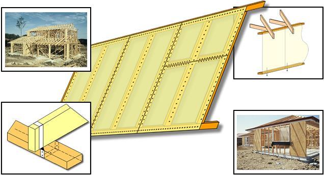
3 Introduction Wind and earthquakes (to a lesser degree in Australia) have historically caused damage to low rise buildings in Australia. These potentially damaging phenomena result in all buildings requiring bracing, especially those with modern open plan design with wide, clear span openings. Structural plywood provides a simple but reliable means to brace these building frames. This manual explains to designers and builders how to brace framing in accordance with the new Limit State revision of AS1684 Residential Timber- Framed Construction. The change to Limit State design provides a more rational design procedure than was possible with permissible stress design. For permissible stress bracing design the design capacities are given in the appendix to this manual. Benefits of using EWPAA Structural Plywood Safety and Reliability Guaranteed by the EWPAA third party audited JAS-ANZ accredited Product Certification Scheme to fully comply with AS/NZS Plywood-Structural. Bonded with durable Marine A Bond. Proven performance based on extensive laboratory testing of full size wall panels. Written into AS1684 Residential Timber- Framed Construction. User friendly Install using simple hand or gun fastener can fasten within 7mm of edges. Cross-laminated plywood construction resists site, impact, and edge damage. Plywood can be installed either vertically, or horizontally, to optimise material usage. Facilitates squaring up of the wall framing. Designed Feasibility & Cost Effectiveness High strength and stiffness in relatively short panels with simple fixings allowing wider window openings and reduced number of bracing walls. Provide safe and reliable bracing during the vulnerable construction period. Why Plywood Bracing The Australian Standard AS Residential Timber-Framed Construction states : Permanent bracing shall be provided to enable the roof, wall and floor framework to resist horizontal forces (racking forces) applied to the building. Appropriate connection shall also be provided to transfer these forces through the framework and sub-floor structure to the building s foundation. The structural plywood bracing systems described in this manual provide a safe and reliable means of permanent bracing that is easy to install and very cost effective. 3
 diaphragm. These forces can be safely and reliably resisted by vertical structural plywood shear walls orientated parallel to the wind direction.")

4 Diagram 1 : Wind Forces Acting on a Building The horizontal wind (racking) forces resulting from the wind flow on the top half of the external cladding are transferred into the ceiling (roof or top floor) diaphragm. These forces can be safely and reliably resisted by vertical structural plywood shear walls orientated parallel to the wind direction. The racking forces from the lower half of the external cladding and those from the plywood bracing are both transferred by the floor (diaphragm) and its supports down into the foundations. If one applies this logic to double storey construction it can be demonstrated the wind forces applied to lower storeys can approach 3 times those on the top storey. This fact, coupled with the trend of having large rooms (with less walls) with wider openings and the use of non-structural linings makes the structural design of these modern buildings more critical. Design Methodology Design Approach 1. Establish the wind forces on the walls of the building, perpendicular to the wind flow in the two primary building directions, viz. normal to the building length and width. These forces can be assessed using AS/NZS Wind Actions Code, AS4055 Wind Loads for Housing or AS1684 Residential Timber- Framed Construction. For convenience, Table 4 provides the wind pressure tables for Wind Classification N2 from AS Select the appropriate structural plywood bracing system or combination of systems. 3. Multiply the selected bracing resistances by the length of each bracing system parallel to the wind direction, ensure the total bracing resistance in these walls equals or exceeds the design wind forces in this direction. Do likewise for the other primary direction. 4

5 Design Parameters 1. Buildings whose plan shape is essentially rectangular or a combination of rectangular elements. 2. Maximum building width of 16m. 3. Maximum roof pitch is Up to 2.7m wall height. Over 2.7m linearly reduce the bracing resistance in the ratio of 2.7m divided by the actual height. The building maximum wall height of 3m, i.e. floor to ceiling height excepting gable or skillion ends. Design Criteria The following design criteria were applied to the full scale prototype tests done in approved Australian laboratories to the requirements of AS Timber Structures Design Methods to establish strength limit states for structural plywood sheathed panels. 1. The allowable deflection (i.e. racking out of square) was limited to panel height/300 or 8mm at the serviceability limit state. 2. Where plywood buckling generated an alternative serviceability limit state the design load was taken within the Limit of Proportionality of the load/deflection plot. That is, design loads were taken prior to the onset of any buckling. The strength limit state (irrespective of its cause) was determined by working backwards from the test panel ultimate load to establish an Equivalent Test Load (ETL). From this the design action effect for the bracing walls was determined. 3. The serviceability limit state loads incorporate a minimum factor of safety of approximately 2.0 on the ultimate failure load of the prototype test panels. Materials Specification Permanent structural bracing enables wall systems to resist horizontal forces i.e. racking forces, applied to the building by wind and/or earthquake. Appropriate connections are required to transfer these forces through a structurally sound system and sub floor to the ground. Thus for safety and reliability of structural bracing the following material specifications are critical. Plywood To comply with the requirements of this manual the plywood must be a minimum of 6mm thick and branded with the EWPAA/JAS-ANZ Tested structural Product Certification stamp. The EWPAA no longer provides any technical support for 3mm, 4.0mm and 4.5mm bracing systems, this includes short wall bracing. The information in this manual cannot be applied to any plywoods less than 6.0mm in thickness. This stamp ensures the plywood has been manufactured to the requirements of AS/NZS Plywood- Structural under the EWPAA/JAS-ANZ accredited third party audited, process based, quality assurance program, and that the plywood will be predictable and reliable making it fit for purpose in this engineered application. 5
6 Framing The framing must be designed to carry the horizontal forces to and from the plywood, In the case of timber the framing must be in accordance with the requirements of AS1684, or framing manual produced in accordance with the design parameters of AS1684. The testing of bracing was done on structural timber of a minimum joint strength of J4 or JD4. Additional testing has verified if the framing is of the lower joint strength JD5 then the design racking resistances must be reduced by 12.5%, requiring a proportional increase in the required bracing wall length. The information in this manual cannot be applied to steel frames, as steel frames do not transfer racking forces to and from the plywood as effectively as timber, and will result in significantly lower racking values. Fasteners Connection of the structural plywood to the framing is critical in bracing. In general, the failure in testing was in the connections. Table 1 specifies the minimum hand or power driven fasteners for timber framing. The following requirements also apply : 1. All fasteners are to be galvanised or suitably coated. 2. The minimum fastener length is as per Table 1, unless the system uses 9mm thick plywood. For systems that use 9mm plywood bracing, the minimum length is 40mm. 3. Minimum edge clearance for fasteners is 7mm. 4. Fasteners are not to be overdriven. 5. Fasteners for structural plywood linings as detailed in the 2.1kN/m and 5.3 kn/m structural plywood bracing systems (click here) can be a minimum of 2.5mm diameter x 40mm bullet head nails. 6. Fasteners with equivalent dimension i.e. head size and shape, shank diameter and length to those in Table 1 are deemed acceptable. 7. The spacing for staples are two thirds (i.e. fastener spacing multiplied by 0.66) those shown for nails or screw. Table 1 : Minimum Fastener Specification Type Model Specifications Flathead structural clouts or 2.80mm x 30mm Hand Driven Nails* connector nails Senco TN22-38 APB 2.33mm x 38mm flathead Bostitch AC45P-250-GW 2.5mm x 45mm flathead Power Driven Nails Jambro B20998 RBC 2.80mm x 32mm zinc plate barb Duo-Fast C27.32GD 2.7mm x 32mm Galvanised Senco N167 BAB Power Driven Staples Bostitch BCS Jambro A10617 G mm * If smaller diameter hand driven nails are used, the spacing of nails can be reduced in the ratio of the basic lateral loads per nail for J4 or JD4 joint group given in Table 4.1 of AS Timber Structures - Design Methods for the lower nail diameter relative to the tabulated load for a 2.8mm diameter nail. When coach screws or bolts are used to fix plywood panels, bottom plates or as tie roads, steel washers must be used. Table 2 provides detail of the minimum allowable washer size. Circular washers of equivalent thickness and nett bearing area are an acceptable alternative. Table 2 : Minimum Steel Washers Screw Washer (mm) M10 Bolt/Coach Screw 38 x 38 x 2.0 M12 Bolt/Coach Screw 50 x 50 x 3.0 M16 Bolt/Coach Screw 65 x 65x 5.0 6

7 Establish Design Racking Forces The limit state design racking forces can be calculated using AS/NZS Wind Actions Code, or more simply, by using the AS1684 Residential Timber-Framed Construction method. The prerequisite for use of this simpler method described below is the design gust wind speed and/or wind classification, and the area of elevation. Maximum Design Gust Wind Speed The wind speed can be established by a number of methods, viz: i. The local government authority may have maps prepared showing wind speed or wind classification zones. ii. The maximum design gust speed can be derived using AS/NZS iii. The wind classification can be established by use of AS 4055 Wind Loads for Housing (a rationalized interpretation of AS/NZS ). Wind Classification The AS1684 wind classification system is a rationalised means of categorising the wind speeds into bands for the non-cyclonic Regions A and B, and the cyclonic Regions C and D. Table 3 shows the various wind classifications in terms of the maximum design gust wind speed. Also included in the table is a multiplier to be applied to the pressures given in Table 4 for other than N2 wind classification. Table 3 : Specification Wind Classification in Terms of Wind Speed Wind Classification Maximum Design Gust Wind Speed (m/s) Multiplier for wind Regions Regions Permissible stress Serviceability Ultimate pressures in Table 4 A and B C and D Design limit State Limit State N N N3 C N4 C C Note: The regions are given in detail in AS/NZS and AS4055. Regions B, C and D occur within 100km of the Australian coast north of the 30 latitude line (i.e. just north of Coffs Harbour). The balance of Australia being designated as Region A. Preservative treated structural plywood serving the dual purposes of cladding & bracing 7
8 Area of Elevation The area of elevation, to which the pressures from Table 4 are applied to calculate the design racking force, is proportional to the wind force applied to the frame of the relevant storey of the building. The area referred to is the area of the full building elevation above half way up the wall frame for the particular storey of the building being assessed. This is illustrated in Diagram 2. The wind direction used shall be that resulting in the greatest load. As wind can blow from any direction, e.g. a single storey dwelling having a gable at one end and hip the other, will result in a higher load at right angles to the width of the house when the gable end is facing the wind. For complex building shapes a combination of shapes may be considered individually and individual loads added together later. Notes: 1. h=half the height of the wall (half of the floor to ceiling height). 2. For lower storey of two storey section h=half of the height of the lower storey (i.e. lower storey floor to lower storey ceiling). 3. The area of elevation of eaves up to 1000mm wide may be ignored in the determination of area of elevation. Diagram 2: Determination of Area of Elevation. 8

9 Design Racking Force The design racking force for each storey or level of the building for each wind direction is the product of the Area of Elevation and the relevant wind pressure for the particular Wind Classification, i.e. Total Racking Force (kn) = Projected Area of Elevation (m 2 ) x Lateral Wind Pressure (kpa) The Lateral Wind Pressures for Wind Classification N2 are given in Table 4. For other Wind Classifications, the pressures from Table 4 are to be factored down or up using the multiplier given in Table 3, e.g. for N1 wind classification the pressures from Table 4 are to be multiplied by Note: In Table 4, 0 degree pitch is provided for interpolation purposes only. Table 4 : Wind Pressures (kpa) on Projected Area for Wind Classification N2 Table 4 (a) : Single storey, upper of two storeys, lower storey or sub-floor all vertical surface elevations (gable ends, skillion ends and flat wall). 9
10 Table 4 (b) : Single storey or upper of two storey long length of building hip or gable ends W (m) Roof Pitch (degrees) Table 4 (c) : Lower storey or sub-floor long length of building hip or gable ends W (m) Roof Pitch (degrees)
11 Table 4 (d) : Single storey or upper of two storey short end of building hip ends W (m) Roof Pitch (degrees) Table 4 (e) : Lower storey or sub-floor short end of building hip ends W (m) Roof Pitch (degrees)

12 Structural Plywood Bracing Systems After establishing the design racking forces for each storey or level and in both primary directions, a building frame can be braced by installing sufficient length of an appropriate system or a combination of the structural plywood bracing systems shown below. It is good practice, where possible, to use bracing in all corners in external walls for each direction and level. Additionally, it is highly desirable to use an even distribution of bracing rather than to concentrate a large proportion of the bracing resistance in a comparatively short length of a high capacity bracing resistance system. The distribution and maximum spacing s are detailed in the section Additional Installation Requirements. The bracing resistances shown in this section apply to wall frames up to a height of 2.7m. For wall heights over 2.7m the bracing is reduced in the ratio of 2.7m divided by the higher wall height, e.g. with a 3m high frame, this reduction factor would be 0.9. For bracing system resistances greater than 6.4kN/m the bottom and top plates must be a minimum of 70 x 45mm MGP10, or 90 x45mm MGP10 or equivalent. If approved staples are used the spacing s are to be a maximum of two thirds those for nails or screws shown in the systems below. The allowable design resistances are appropriate to all species, joint strength groups to J4 or JD4 and stress grades of wall framing timber. This covers most Australian hardwood and exotic pines. If species of JD5 joint strengths are used then additional testing has shown that the design values should be reduced by 12.5%. Imported unidentified softwood may fall into this category. With the exception of the 17.4 kn/m system which is sheathed both sides, the bracing resistances in this section are applicable to frames sheathed one side only. The resistances are additive for frames sheathed on two sides. However, the hold down requirements of the bottom plate must also be increased accordingly. Bottom and top plate sizes must be, as a minimum, those given in the section Additional Installation Requirements. 12


13 3 kn/m Capacity Bracing System This system uses a minimum thickness of 7mm, F8 structural plywood at a maximum stud spacing of 600mm. This system may be used for sheathed sections less than 900mm wide, provided the appropriate reduction factor from the section entitled Short Wall Bracing Systems is applied to the 3 kn/m bracing capacity. As indicated, fastener centres are 100mm Top and Bottom Plate, 100mm Vertical Edges, 100mm Intermediate Studs. Horizontal Butt Joints permitted provided plywood is fixed to nogging at 100mm centres. No other nogging is required. 3.4 kn/m Capacity Bracing System This system may be used for sheathed sections less than 900mm wide, provided the appropriate reduction factor from the section entitled Short Wall Bracing Systems is applied to the 3.4 kn/m bracing capacity. As indicated, fastener centres are 150mm Top and Bottom Plate, 150mm Vertical Edges, 300mm Intermediate Studs. The minimum structural plywood thicknesses for this system are : Plywood Stress Grade Stud Spacing 450 mm 600mm F8 7 9 F11-7 Horizontal Butt Joints permitted provided plywood is fixed to nogging at 150mm centres. No other nogging is required. 13
14 3.4 kn/m Capacity Bracing System Utilising Nogging This system uses a minimum thickness of 7mm, F8 structural plywood at a maximum stud spacing of 600mm. This system may be used for sheathed sections less than 900mm wide, provided the appropriate reduction factor from the section entitled Short Wall Bracing Systems is applied to the 3.4 kn/m bracing capacity. As indicated, fastener centres are 150mm Top and Bottom Plate, 150mm Vertical Edges, 150mm Nogging, 300mm Intermediate Studs. Horizontal Butt Joints permitted provided plywood is fixed to nogging at 150mm centres. No other nogging is required. 1 row of Nogging, Staggered or Single Line at half wall height. 6 kn/m Capacity Bracing System This system may be used for sheathed sections less than 900mm wide, provided the appropriate reduction factor from the section entitled Short Wall Bracing Systems is applied to the 6 kn/m bracing capacity. As indicated, fastener centres are 50mm staggered Top and Bottom Plate, 150mm Vertical Edges, 300mm Intermediate Studs. Sheathed panels are to be connected to sub-floor by a minimum of 13kN tie downs at each end, and every 1200mm. The minimum structural plywood thicknesses for this system are : Plywood Stress Grade Stud Spacing 450 mm 600mm F8 7 9* F * 7mm F8 can be substituted for 9mm F8 provided that racking resistances are reduced by 0.9. Horizontal Butt Joints permitted provided plywood is fixed to nogging at 50mm centres. No other nogging is required. 14
 and a minimum of 330mm wide provided the appropriate reduction factor is used.")
15 6.4 kn/m Capacity Bracing Systems This system is only applicable to sheathed sections a minimum of 800mm wide (reduction factor 1.0) and a minimum of 330mm wide provided the appropriate reduction factor is used. As indicated, fastener centres are 150mm staggered Top and Bottom Plate, 150mm Vertical Edges, 300mm Intermediate Studs. Sheathed panels are to be connected to sub-floor by a minimum of 13kN tie downs every 1200mm between rods. For details of rod installation, please refer to the Rod Installation Details section. The minimum structural plywood thicknesses for this system are : Plywood Stress Grade Stud Spacing 450 mm 600mm F8 7 7 F M12 rod top to bottom plate, securely anchored into the sub floor, each end of sheathed section. Horizontal Butt Joints permitted provided plywood fixed to nogging at 150mm centres. 15
16 8.7 kn/m Capacity Bracing Systems This system is only applicable to sheathed sections a minimum of 900mm wide. There are two options that can achieve 8.7 kn/m : 1. A minimum thickness of 6mm, F11 structural plywood at a stud spacing of 450mm centres. For this option, bottom and top plates must be a minimum of 70 x 45mm MGP10 (or equivalent), and the maximum width of a sheathed section is 1.8m. 2. A minimum thickness of 7mm, F11 structural plywood at a stud spacing of 6000mm centres. For this option bottom and top plates must be a minimum of 90 x 45mm MGP10 (or equivalent), and the maximum width of a sheathed section is 2.4m. As indicated, fastener centres are 50mm Top and Bottom Plate, 100mm Vertical Edges, 100mm Intermediate Studs. Sheathed panels are to be connected to sub-floor by a minimum of 13kN tie downs every 600mm between rods. For details of rod installation, please refer to the Rod Installation Details section. M12 rod top to bottom plate, securely anchored into the sub floor, each end of sheathed section. Horizontal Butt Joints permitted provided plywood fixed to nogging at 50mm centres. 16

17 17.4 kn/m Capacity Bracing Systems (8.7 kn/m per Side) These systems are sheathed both sides with F11 structural plywood. These systems are only applicable to sheathed sections a minimum of 900mm wide. The two options for these systems are : Framing Timber Specification Option Max Stud Plywood Min Max Section Min Size Min Min Joint Spacing (mm) Thickness (mm) Width(m) (mm) Grade Strength Group x 45 MGP 10 JD x 45 MGP10 JD5 As indicated in the diagram below, fastener centres are 50mm Top and Bottom Plate, 100mm Vertical Edges, 100mm Intermediate Studs. M12 rod, capable of developing a minimum of 90 x 45 MGP10, JD5 12kN uplift resistance, connected to the top to bottom plate, securely anchored into the sub A testing program was conducted at the University of floor at each end of sheathed section. Central Queensland, Rockhampton during October 2009 to determine whether the 8.7 kn/m capacity bracing system, sheathed both sides, required special consideration to be applied to the design of the top and bottom plates. The tests revealed that 90 x 45 MGP10, JD5 framing sheathed with 7mm F11 DD structural plywood fixed to sheathed sections 2.4m high x 2.4m wide with the nailing pattern and hold down arrangement shown below and the hand driven nail specifications given in Table 1 could sustain a bracing capacity of 17.4 kn/m. Sheathed panels are to be connected to Sub-floor by a minimum of 3 x 12mm tie down bolts located within 100mm of studs for 600mm stud spacing s (shown in red in the diagram to the right). 70 x 45 MGP10, JD5 The testing program also showed that the 70 x 45 MGP10, JD5 system could not sustain a bracing capacity of 17.4 kn/m on a 2.4m high x 2.4m wide sheathed section. However, this framing system configured identically to the 90 x 45mm system (stud spacing s exempted) can resist 17.4 kn/m on a 2.4m high x 1.8m wide sheathed section. M12 rod, capable of developing a minimum of 12kN uplift resistance, connected to the top to bottom plate, securely anchored into the sub floor at each end of sheathed section. Sheathed panels are to be connected to Sub-floor by a minimum 2 x 12mm tie down bolts located mid-way between centre stud and studs either side (shown in blue in the diagram to the right). 17


18 Rod Installation Details Where a bracing system requires rods, these rods must be fitted no more than 150mm away from the edge of the panel as shown below : Top Plate Detail Bottom Plate Into Concrete Slab Bottom Plate Detail Into Timber Member 18
19 Short Wall Bracing Systems The minimum width for plywood sheathed bracing systems is 900mm. Where shorter sections are required as discrete panels, the following reduction factors apply : Width of Sheathed Section (m) Reduction Factor Sheathed sections which are less than 900mm and greater than or equal to 330mm in width for panel racking capacities of 3.0 kn/m to 6.0 kn/m a reduction factor of 1 applies to panels fitted with an M12 anti-rotation rod 100 mm from the outside edge of the studs at each end and secured to the slab or sub floor with nuts and 50 x 50 x 3 washers. Internal Lining Bracing Systems Decorative structural plywood wall lining fixed with 2.5mm diameter x 40mm bullet head nails can provide bracing resistance against wind loads. The nails may be punched just below the plywood surface and the holes filled with suitable putty. In grooved plywood lining the nails may be located in the grooves and punched flush. 2.1 kn/m Capacity Bracing System using Structural Plywood Lining This system uses a minimum glue/nailed lining thickness of 6mm, F11 structural plywood at stud spacing s of 450mm or 600mm. This system is only applicable to sheathed sections a minimum of 900mm wide. As indicated, fastener centres are 100mm Top and Bottom Plate, 100mm Vertical Edges, 200mm Intermediate Studs. Horizontal Butt Joints permitted provided plywood fixed to nogging at 100mm centres. 19
20 5.3 kn/m Capacity Bracing System using Structural Plywood Lining This system is only applicable to sheathed sections a minimum of 900mm wide. A continuous 6mm bead of a elastomeric adhesive is to be applied to framing timbers of all nailed plywood joints. A double glue bead is to be used where plywood sheets butt together on a stud or nogging As indicated, fastener centres are 200mm staggered Top and Bottom Plate, 200mm Vertical Edges, 200mm Intermediate Studs. Sheathed panels are to be connected to Sub-floor by a minimum of 13kN tie downs at each end, and every 1200mm along the bottom plate. The minimum structural plywood glue/nailed lining thicknesses for this system are : Stud Spacing Plywood Stress Grade 450 mm 600mm F Horizontal Butt Joints permitted provided plywood fixed to nogging at 200mm centres. 20

21 Additional installation Requirements General To ensure the maximum effectiveness of structural plywood bracing the additional installation requirements detailed in this section are critical. The even distribution and maximum spacing of the bracing panels is vitally important to the structural performance of the structure. The tie down of the bottom plate against in-plane forces, and the panels against overturning forces within the building framework, are crucial to the performance of the bracing, In addition there must be sufficient structural connection between the ceiling/roof diaphragms and the top of the bracing walls to transfer the forces through the structure to the shear wall then down to the ground. All fasteners shall be a minimum of 7mm from the plywood edges. All plywood panel butt joints, either at vertical or horizontal edges, must be via connection of each panel to a common noggin or stud. Unattached panel edges or fly joints are not permitted. Each plywood bracing panel must be effectively fastened to the top and bottom plates and studs. In cases where secondary (ribbon) top plates are employed and the plywood bracing has been fixed to lower to plate, the two plates must be connected together with fasteners of equivalent lateral shear capacity to the plywood bracing. Distribution and Spacing of Bracing Walls The bracing should be approximately evenly distributed throughout the building and provided in both primary directions. Where possible, bracing should be placed at the external corners of the building, with the balance evenly distributed in the external and internal walls. The object is to distribute the bracing in proportion to the areas of elevation, which, as these areas are proportional to the design racking forces, will result in the most effective structural solution for the building. Adherence to this recommendation will also, very importantly, minimise any tendance of the building to twist. The other important criteria for distribution of the bracing is the maximum distance between bracing panels parallel to wind direction. Too large a distance will result in excessive forces being transferred to nonstructural elements of the building. For wind classifications up to and including N2 this distance must not exceed 9000mm. For higher wind classifications the maximum spacing is to be in accordance with Table 5 for the relevant wind classification, ceiling depth and roof pitch. Maximum spacing as per Table 5 between bracing walls for wind direction B Maximum spacing as per Table 5 between bracing walls for wind direction A Notes : 1. Internal wall bracing can be cupboard backs or in rooms with shorter walls 2. Where possible, some bracing should be placed at all external corners of the building. 21
22 Where bracing cannot be placed in external walls because of openings and the like, a specifically designed structural plywood diaphragm floor, portal frame, ceiling or roof can be used to transfer racking forces through to bracing walls designed to carry the loads. For guidance regarding the design of those structural components please refer to the relevant chapters of the EWPAA s Structural Plywood and LVL Design Manual available from the EWPAA's web site. Table 5 : Maximum Spacing of Bracing Walls in Single Storey or Upper Storey of Two- Storey Construction for - (a) For N1 and N2 Wind Classifications, the maximum bracing wall spacing is 9m. (b) N3 and C1 Wind Classification Ceiling Maximum Bracing Wall Spacing (m) Depth Roof pitch (Degrees) (m) Note: Spacing of bracing in the lower storey of two storey construction is to be evenly distributed, with the maximum spacing of bracing sets under a timber floor system to be: a) 14m for N1 and N2, if the minimum floor width is 4.8m b) 14m for N3 and C1, if the minimum floor width is 6m c) 11.5m for N4 and C2, if the minimum floor width is 6m d) 10m for C3, if the minimum floor width is 6m 22
23 (c) N4 and C2 Wind Classification Ceiling Maximum Bracing Wall Spacing (m) Depth Roof pitch (Degrees) (m) (d) C3 Wind Classification Ceiling Maximum Bracing Wall Spacing (m) Depth Roof pitch (Degrees) (m) Notes: For wind classifications refer to Table 3. Where a structural plywood diaphragm ceiling is used for classification N4 or C3 the maximum spacing s may be increased by multiplying the spacing in Table 5d by 1.5 provided the resulting bracing wall spacing does not exceed 9m. 23

24 Fixing of Bottom of Bracing Walls The horizontal forces due to wind and earthquakes being resisted by bracing walls results in two separate types of action on the bracing panels. The first action is an in-plane sliding force pushing on the bottom plate. Sufficient fixings of the bottom plate to the sub-floor can be designed to resist this in-plane shear force, The second action is due to rotation or overturning and is best resisted by tie rods extending from the top plate to the sub-floor and located at each end of bracing wall. For the lower capacity bracing walls, nominal connection of the bottom plate to the sub-floor can overcome these overturning moments. Bottom plate fixing for up to 3.4kN/m Systems No additional bottom plate fixing is required for these lower capacity bracing systems. Obviously, nominal bottom plate fixing as specified in AS1684 is still required. However, if the 3.4kN/m system is used on both sides of a frame to double the bracing capacity in that section of wall, then the bottom plate fixing will need to be upgraded to be equivalent for a 6.4kN/m system. Table 6 details nominal bottom plate fixings. Table 6 : Nominal Bottom Plate Fixing for up to 3.4kN/m Bracing Wind classification Concrete Slab Sub-floor Up to 38mm Thick Plates to Joists 38mm to 50mm Thick Plates to Joists N1,N2,N3,N4 and C1,C2 and C3 75mm masonry nails, screws or bolts at 1200mm max. spacing 2/3.05mm nails x 75mm long at 600mm max. centres 2/3.05mm nails x 90mm long at 600mm max. centres Bottom Plate Fixing for 5.3, 6.0 and 6.4 kn/m Systems The minimum fixing requirement for 5.3, 6.0 and 6.4 kn/m bracing capacity systems is 13kN tie down every 1200mm along the bottom plate or equivalent. A looped 30mm x 1mm width galvanised looped strap as shown in Diagram 4 is equivalent to 13kN tie down. Diagram 4: Looped strap Bottom Plate Fixing The tie down capacity of some bolts through a range of timber joint strengths are presented in Table 7. If the bolts are used in concrete slabs they must be appropriately embedded. For lower capacity bolted joints the resistance can be obtained by reducing the spacing of the bolts. 24

25 Table 7 : Tie Down Capacity of Bolts through Timber Bolt Tie Down Capacity (kn) Washer Size, Classification J2 J3 J4 JD4 JD5 JD6 mm M x 38 x 2.0 M x 50 x 3.0 M x 65 x 5.0 Bottom Plate Fixing for 8.7kN/m Systems The minimum fixing requirement as used in the actual testing of 8.7kN/m bracing capacity systems is 13kN tie down every 600mm along the bottom plate or equivalent. Reference to the tie down capacities shown in Table 7 provides some guidance. Uplift Resistance of Structural Plywood Sheathed Walls Plywood sheathed wall frames can provide roof hold-down by transferring the wind uplift loads through the rafter or trusses to the top plate, then from the top plate to the bottom plate through the plywood acting in tension. The loads are then transferred to the sub-floor or floor by the appropriate connection of the bottom plate to floor joists or concrete slab. Note that where high concentrated loads are present and additional tie downs are required, these cases are not covered in the scope of this manual and should be referred to an engineer. The bottom plate to sub-floor fixing must be at least 13kN tie down every 1200mm along the bottom plate or equivalent to meet the required uplift. Connection of the plates to the plywood is critical. When installed as specified in Table 8, the plywood sheathed wall sections act as a continuous cyclone rod thereby avoiding stress concentrations. The uplift resistances given in Table 8 were based on prototype testing full size panels. Diagram 5: Uplift Resistance of Plywood Sheathed Wall Frames 25

26 Table 8 gives the ultimate uplift resistance in kn per rafter for two plywood to top and bottom plate connection methods. The fastener specification is as detailed in Table 1 and the uplift resistances apply to all the plywood thicknesses and stress grades given in the Structural Plywood Bracing Systems section (click here). A single 900mm bracing panel can provide the specified uplift resistance for a rafter if the rafter is fixed a minimum of 300mm from either end of the plywood panel as shown in Diagram 5. Table 8 : Ultimate Uplift Resistance of Plywood Sheathed Wall Systems Ultimate Uplift Fastener Spacing (mm) Resistance Hand or Power (kn/rafter) Driven Nails Staples Note: The above information is only applicable for bracing systems using plywood that is at least 6mm in thickness. The design of the rafter or truss to top plate connection is critical. The connection design must comply with AS1684. The connection shown in Diagram 6a is acceptable for uplift resistances up to 13kN/rafter. Diagram 6a: Connection of Top Plate to Rafter or Truss 26

27 When installed as shown in diagram 6b (with the rafter or truss chord finishing directly over a stud and a Galvanised steel strap fixed directly to each side of the stud with at least 11 nails) the uplift resistance will be 13kN/rafter: Diagram 6b: Connection of Top Plate and Stud to Rafter or Truss For a nailing pattern of 100/150/150, one strap nailed identically to Diagram 6b will develop an uplift resistance of 10.0kN for that rafter. Fixing of Top of Bracing walls If the horizontal forces due to wind or earthquakes in the ceiling/top floor/roof diaphragm are to be transferred into the wall bracing there must be sufficient structural connection between the two. Internal Bracing Walls All internal bracing walls have to be fixed to the ceiling or roof frame and /or to the external wall frame with structural connections of equivalent shear capacity to the bracing capacity of the particular wall. AS1684 provides a range of suitable connections. 27
28 External Bracing Walls Under Ends of Eaves If external walls under ends of eaves are used as bracing walls they have to be structurally connected to the main ceiling diaphragm. This can be achieved by fixing structural plywood bracing to the rafter overhangs and connecting the panel to the top of the bracing wall and to the ceiling diaphragm with equivalent nailing to the wall bracing (Refer Diagram 7). These bracing walls are to be limited to 20% of the total wall bracing for that direction. Diagram 7: Plan View External Bracing Under Ends of Eaves Holes Through Plywood Bracing During construction, for various reasons, tradespeople often wish to make penetrations through structural plywood bracing panels. A neat hole (i.e. not over cut) of up to 100mm x 100mm within an envelope of 100mm from the vertical and top edges and 200mm of the bottom edge of the bracing pane will have no significant effect on the bracing capacity. Multiple 100mm x 100mm holes are allowable within the envelope but their centres must be no closer than 600mm. One hole of up to 400mm x 400mm located between the studs and within the envelope defined above, with nogging framing the hole and fixing of the plywood to the framing as per the requirements for the top and bottom plate is acceptable. Design Example Determine the bracing requirements for a 15m x 9m double storey gable roofed dwelling with 20 roof pitch and 2.7m ceiling heights as shown in Diagram 8. Assume the Local Authority has advised the Wind Classification for the site to be N2. 28

29 Diagram 8: Building Dimensions for Design Example Firstly, the wind forces to be resisted by the building frames in both primary directions and for both storeys need to be established. As the wind Classification has been given, the next step is to calculate the Area of Elevation using the dimensions from Diagram 8 as detailed in Table 9. Table 9 : Areas OF Elevation for Design Example Storey Upper Lower Wind Area of Calculation Direction Elevation (m 2 ) A 15m x 3.0m 45.0 B (9m x 1.35m) + (9m x 1.64m)/ A 15m x 5.7m 85.5 B (9m x 4.05m) + (9m x 1.64m)/ The second step, as detailed in Table 10, is to calculate the Design Racking Forces for each primary direction and storey using the Area of Elevation and the relevant Wind Pressure from Table 4. Table 10 : Design Racking Forces for Design Example Storey Upper Lower Wind Direction Area of Elevation Wind Pressure (kpa) Calculation Design Racking Force (kn) A Table 4(b) 45.0 x B Table 4(a) 19.5 x A Table 4(c) 85.5 x B Table 4(a) 43.8 x Note: For other Wind Classifications the Design Racking Force can now be reduced or increased using the multiplier given in Table 3. 29
30 The final step is to select the appropriate bracing systems and calculate the minimum number of structural plywood bracing panels required per storey. In selecting the bracing systems it is good practice to use lower capacity systems in top storey or single storey frames and higher capacity systems in lower storey frames. This practice lends itself to having bracing placed in all the building corners and meeting the maximum structural bracing spacing requirements. If it is decided the rodded systems (6.4 kn/m, 8.7 kn/m and 17.4 kn/m systems) will not be specified then the 6kN/m close nailed system will be the one with the largest capacity. For this design example we will nominate 3.4kN/m systems on the top floor and 6kN/m on the lower floor. Additionally, we will assume the stud spacing to be 450mm, thus 900mm wide structural plywood panels would be the most practical panel width. Table 11 shows how to calculate the minimum bracing requirements. Table 11 : Calculation of Number of Bracing Panels Required for Design Example Storey Wind Direction Calculation Force / Capacity Bracing Required (m) Number of 900mm Panels Required Upper Lower A 27.5 / B 17.9 / A 61.6 / B 40.3 / / 0.9 = 9.0 i.e. 3.4 kn/m 5.3 / 0.9 = 5.9 i.e. 3.4 kn/m 10.3 / 0.9 = 11.4 i.e. 6 kn/m 6.7 / 0.9 = 7.4 i.e. 6 kn/m Table 11 provides one option for minimum AS1684 bracing requirements, and all that remains now is to evenly distribute the panels throughout the framing. To brace the frames in both storeys for wind direction B, installation of the plywood in the front and back 15m walls of both storeys, preferably at each corner, would meet the Code requirements as these walls are 9m apart the maximum allowed in Table 5 for wind Classifications N1 and N2. The bracing of the framing for wind direction A will require some of the bracing to be installed in internal walls, as the relevant external walls are spaced at 15m. These panels can be located in the backs of built-in cupboards, or on the walls of smaller rooms, e.g. toilets. Decorative structural plywood wall panelling is another alternative. It must be remembered these internal bracing walls have to be structurally connected to the ceiling /roof framing to be effective as bracing. 30
31 Appendix Permissible Stress and Serviceability Limit State Design Capacities For reference, Table 12 lists the appropriate permissible stress capacities for the structural plywood bracing systems detailed in this brochure. Table 12 : Permissible Stress and Serviceability Limit State Bracing Capacities Design Bracing System Strength Limit State Permissible Stress and Serviceability Capacity (kn/m) Limit State Design Capacity (kn/m) 3 kn/m kn/m kn/m with nogging kn/m kn/m kn/m kn/m kn/m
32 Revision History Revision Changes Date Who Renamed racking resistance reduction factors section to Short Wall Bracing Systems and clarified that these factors are 1 under certain conditions. Added a clarification on rod installation details. Made it clear that the section on uplift resistance does not apply 7 to sections which have high concentrated roof loads. MM, Added a section on uplift resistance when rafter over stud and MB properly strapped. This was based on recent testing. Fixed errors in the design example. Made it clear that fasteners for 9mm or thicker plywood must be a minimum of 40mm. Clarified that tie down fixings for bottom plates must use washers. Tables 4b and 4c modified to match those in AS Added a new section - Plate Sizing and Fixing for 8.7kN/m Systems Sheathed Both Sides. Clarified that Table 8 is actually Ultimate Uplift Resistance of Plywood Sheathed Wall Systems and not the Allowable uplift resistance. Updated all stamps and logos to current version. Clarified the Length and Width dimensions in Table 4 and replaced images. Clarified the tie rod requirements they need to be securely anchored to the sub floor. In the 6.4 kn/m system, removed the exception of tie rods being not mandatory in the case of openings they are mandatory. Clarified the requirements for washers in Racking Resistance Reduction Factors for Sheathed Systems less than 900mm. Also reduction factors now only apply to the 3.4 kn/m systems and not to the 6.4 kn/m system. Clarified requirements for top and bottom plates in the 8.7 kn/m system. This system now also has a 1.8m maximum length for 70 x 45 plates, and a maximum length of 2.4m for 90 x 45mm plates. Clarified the Appendix by indicating that it is the Permissible Stress and Serviceability Limit State Design Capacities and not just Permissible Stress Design Capacities. Added a new 17.4kN/m system sheathed both sides. Minor formatting and grammar changes, and some minor clarifications MM, MB 5 Reformat and image / graphic revamp. Added a disclaimer that the information in this manual cannot be applied to steel frames. Added clarification to systems sheathed on both sides, and the difficulties in determining tie down requirements. Added a note that plywood can be installed either horizontally and vertically. Added several clarifications to ensure that the information in this manual can only be applied to plywood 6mm thick or greater. 10/02/2009 MB 32
33 4 3 Table15 Bottom plate fixing has been updated. Corrected some table references Replace back page to standard EWPAA back page General formatting tidy Updated the diagram for Table 10, to remove the requirements for 70 x 70 bottom plates. General formatting tidy. 1/08/2007 BL 23/02/2007 MB 33
34 EWPAA Members Plywood and Laminated Veneer Lumber (LVL) Member Name Location Phone Fax Web Ausply NSW Austral Plywoods Pty Ltd QLD Big River Group Pty Ltd NSW Carter Holt Harvey Woodproducts Australia (Plywood) Myrtleford VIC Carter Holt Harvey Woodproducts Australia Nangwarry LVL SA Carter Holt Harvey Woodproducts - Marsden Point LVL NZ Carter Holt Harvey Woodproducts (Plywood) - Tokoroa NZ Fiji Forest Industries FIJI IPL (West Coast) Ltd NZ Juken New Zealand Ltd (Gisborne) NZ Juken New Zealand Ltd (Wairarapa) NZ Nelson Pine Industries Ltd NZ PNG Forest Products Ltd PNG RH (PNG) Ltd PNG Valebasoga Tropikboards Ltd FIJI Wesbeam Pty Ltd WA Particleboard and MDF Member Name Location Phone Fax Web Alpine MDF Industries Pty Ltd VIC Borg Panels Pty Ltd NSW Carter Holt Harvey Woodproducts Australia NSW D & R Henderson Pty Ltd NSW Laminex VIC Tasmanian Wood Panels (Aust) TAS Weathertex Pty Ltd NSW Visit the EWPAA Website to get the latest information. Visit EWPAA Member List to ensure your products carry genuine EWPAA certification 34
ENGINEERED STRUCTURAL BRACING
 ENGINEERED STRUCTURAL BRACING www.r6brace.com.au 2 R6 Brace Key Features Complies with BCA Tested & certified by the Engineered Wood Products Association of Australasia (EWPAA) Performs in all weather
FEATURING PLYWOOD IN BUILDINGS. Plywood Used in So Many Different Ways
 FEATURING PLYWOOD IN BUILDINGS Plywood Used in So Many Different Ways Table of Contents Introduction... 3 Plywood Characteristics... 3 Cross Laminated Two Way Strength and Stability... 3 Face Quality...
LVL8 H1.2 GENERAL FRAMING. Eco Friendly Revolutionary H1.2 Treatment Azotek by Zelam
 LVL8 H1.2 GENERAL FRAMING Eco Friendly Revolutionary H1.2 Treatment Azotek by Zelam NPIL/MARCH2015 Introduction to NelsonPine LVL8 H1.2 NelsonPine LVL is an engineered wood composite made from rotary peeled
3.1 General Provisions
 WOOD FRAME CONSTRUCTION MANUAL 107 3.1 General Provisions 3.1.1 Prescriptive Requirements The provisions of this Chapter establish a specific set of resistance requirements for buildings meeting the scope
nam4t/m6 ubracreboaardl
 natural al M4/M6 BRACEBOARD COMPANY OVERVIEW Australian Hardboards Limited is the sole Australian manufacturer of 100% all natural thin hardboards. Well established, our greatest strength is our ability
VERSA-LAM. An Introduction to VERSA-LAM Products
 44 VERSA-LAM An Introduction to VERSA-LAM Products VERSA-LAM is one of the strongest and stiffest engineered wood products approved in the UK. 241 302 356 406 VERSA-LAM products are excellent as floor
Pryda Timber Connectors
 Pryda Timber Connectors Pryda Lintel Guide Engineered Steel Wall Lintels March 2014 ESSENTIAL NOTES PRYDA PRODUCT GUIDES INTRODUCTION The information in this Product Guide is provided for use in Australia
WHY YOU SHOULD USE TUFFLOOR. components
 Tuffloor DESIGN GUIDE WHY YOU SHOULD USE TUFFLOOR Strong and Easily Installed Tuffloor is a steel floor framing system designed for strength and ease of installation, and is an easy and economical alternative
Design Guide Pryda Connectors for Steel Framing
 Pryda Connectors for Steel Framing Copyright: (c) Pryda Australia A Division of ITW Australia November 2012 November 2012 Design Guide Pryda Connectors for Steel Framing INDEX General Notes General information
os brace The environmentally sustainable bracing panel
 os brace The environmentally sustainable bracing panel www.egger.com/osbrace THE ENVIRONMENTALLY SUSTAINABLE BRACING PANEL WHAT IS OS Brace? OS Brace is a high quality, moisture resistant, innovative and
Site Installation Guide
 Site Installation Guide Site Checklist Stop and read this now. Tick box when checked. Floor Joist Layout If a floor joist design/layout was done, was a site copy of the layout provided with the joists,
THE ENGINEERED WOOD ASSOCIATION
 D A T A F I L E APA Performance Rated Rim Boards A rim board is the wood component that fills the space between the sill plate and bottom plate of a wall or, in second floor construction, between the top
Building for High Wind Resistance in Light-Frame Wood Construction
 Building for High Wind Resistance in Light-Frame Wood Construction DESIGN GUIDE Meeting the Challenge of High Wind Design Designing a structure to withstand the devastating forces of tornados is one of
Pryda Timber Connectors
 Pryda Timber Connectors A complete guide to the design, specification and installation of Pryda Bracing March 2014 ESSENTIAL NOTES PRYDA PRODUCT GUIDES INTRODUCTION The information in this Product Guide
ROOF-CEILING CONSTRUCTION
 CHAPTER 8 ROOF-CEILING CONSTRUCTION SECTION R801 GENERAL R801.1 Application. The provisions of this chapter shall control the design and construction of the roof-ceiling system for all buildings. R801.2
T-BRACE / I-BRACE DETAIL WITH 2X BRACE ONLY
 August 10, 2010 T-BRACE / I-BRACE DETAIL WITH 2X BRACE ONLY ST - T-BRACE 2 R MiTek Industries, Chesterfield, MO Page 1 of 1 Note: T-Bracing / I-Bracing to be used when continuous lateral bracing is impractical.
SECTION R507 DECKS DECKING LEDGER BOARD BEAM. FOOTING BEAM SPAN CANTILEVER For SI: 1 inch = 25.4 mm FIGURE R507.2 DECK CONSTRUCTION
 SECTION R507 DECKS R507.1 Application. The provisions of this section shall provide prescriptive requirements for the design and construction of all uncovered, wood-framed, single-span exterior decks.
Exterior Wall Fastener Schedule
 City of Republic Community Development Department Exterior Wall Fastener Schedule REVISION DATE: JANUARY 2017 Design and construction (2012 IRC Section R602.3): Exterior walls of wood frame construction
3. Are component and cladding design pressures consistent with ASCE 7 for the wind speed and exposure category (ASCE 7 Fig. 6-3)?
?") Mobile County Public Works Residential Plan Reviewers Checklist For Structural Requirements of Wood Framed Residences Recommendation: Permit as Noted Revise Plans and Resubmit MCPW Ref. No. Design Criteria:
Mobile County Public Works Residential Plan Reviewers Checklist For Structural Requirements of Wood Framed Residences Recommendation: Permit as Noted Revise Plans and Resubmit MCPW Ref. No. Design Criteria:
APA Performance Rated Rim Boards
 D a t a F i l e APA Performance Rated Rim Boards A Rim Board is the wood component that fills the space between the sill plate and bottom plate of a wall or, in second floor construction, between the top
AS Residential timber-framed construction. Part 2: Non-Cyclonic Areas
 AS 1684.2 2010 Residential timber-framed construction Part 2: Non-Cyclonic Areas AS This Australian Standard was prepared by Committee TM-002, Timber Framing. It was approved on behalf of the Council of
Strong, lightweight composite structural I -Beam.
 Strong, lightweight composite structural I -Beam. This Installation Guide has been prepared as a source of information to provide general guidance to consultants and in no way replaces the services of
Fastener Schedule. a, b, c. FASTENER Roof 3-8d (2 1 / ) / ) 3-10d. 3-10d ( ) 3-16d box nails. (3 1 2 toe nails on one side
 / ) 3-10d. 3-10d ( ) 3-16d box nails. (3 1 2 toe nails on one side") ITEM 1 DESCRIPTION OF BUILDING ELEMENTS Blocking between joists or rafters to top plate, toe 2 Ceiling joists to plate, toe 3 4 5 6 Ceiling joists not attached to parallel rafter, laps over partitions,
ITEM 1 DESCRIPTION OF BUILDING ELEMENTS Blocking between joists or rafters to top plate, toe 2 Ceiling joists to plate, toe 3 4 5 6 Ceiling joists not attached to parallel rafter, laps over partitions,
 JOIST DETAILS Plate nail, 16d (0.15" x 1 ") at 1 on-center Blocking panel: 1 1 8" TJ Rim Board, 1 1 TimberStrand SL or TJI joist Toe nail, 10d (0.11" x ") at on-center A1 CS BEAM DETAILS L1 eb stiffener
Sections & Details VOCABULARY
 1 Sections & Details VOCABULARY 1 ROOF FRAMING DETAIL RIDGE BOARD SHEATHING SHINGLES WEB FASCIA RAFTER (chord) SOFFIT SHEATHING STUD INSULATION DOUBLE TOP PLATE CEILING JOIST 2 FOUNDATION DETAIL STUD SHEATHING
Featuring TJ Rim Board and TimberStrand LSL
 #TJ-8000 SPECIFIER S GUIDE TRUS JOIST RIM BOARD Featuring TJ Rim Board and TimberStrand LSL Multiple thicknesses, grades, and products to cover all your rim board needs 1¼" Thickness matches lateral load
PART II ENGINEERED BASIS OF RIDGE AND EAVE VENT DETAILS
 PART II ENGINEERED BASIS OF RIDGE AND EAVE VENT DETAILS A - INTRODUCTION This report addresses engineered design for unblocked wood structural panel (plywood or OSB) roof diaphragms with either continuous
Introducing AJSTM INSTALLATION GUIDE USA. 8 th Edition USA
 The SIMPLE FRAMING SYSTEMSM INSTALLATION GUIDE USA for Floors This Installation Guide is intended to provide general information for the designer and end-user. For further information, please refer to
BRACING BRACING SECTION 7 SECTION 7
 If we are to learn from the past, it is clear that there is generally a lack of understanding of the purpose of roof bracing and who should be responsible for it. This has led to disputes, claims and,
Load-carrying capacity of timber frame diaphragms with unidirectional support
 Load-carrying capacity of timber frame diaphragms with unidirectional support Jørgen Munch-Andersen, Danish Timber Information, 2012-06-26 Introduction The rules for determining the load-carrying capacity
APPENDIX 1 : Post and Beam Model
 Good Practice Guide to Hut Building Prepared by Reforesting Scotland s Campaign for a Thousand Huts (5th Draft) APPENDIX 1 : Post and Beam Model Peter Caunt & Bernard Planterose June 2017 www.thousandhuts.org
Structural Criteria for Residential Flush-Mounted Solar Arrays
 Structural Criteria for Residential Flush-Mounted Solar Arrays Planning and Development Building & Safety Division 1. ROOF CHECKS A. Visual Review/Contractor s Site Audit of Existing Conditions: 1) Is
A Shell construction
 A Shell construction A 4/2012 Content 1 BASE AND WALL ANCHORING 1.1 Base with mortar bed 1.2 Base with sill plate 1.3 Base with raised sill plate 1.4 Concrete base (mortar bed) 1.5 Concrete base (sill
Attachment of Residential Deck Ledger to Metal Plate Connected Wood Truss Floor Systems Overview Revised 9/2/2016
 Attachment of Residential Deck Ledger to Metal Plate Connected Wood Truss Floor Systems Overview Revised 9/2/2016 SBCA has been the voice of the structural building components industry since 1983, providing
Pryda Timber Connectors
 Pryda Timber Connectors A complete guide to the design, specification and installation of Pryda High Capacity Products March 2012 ESSENTIAL NOTES PRYDA PRODUCT GUIDES INTRODUCTION The information in this
ROOF-CEILING CONSTRUCTION
 CHAPTER 8 ROOF-CEILING CONSTRUCTION SECTION R801 GENERAL R801.1 Application. The provisions of this chapter shall control the design and construction of the roof-ceiling system for all buildings. R801.2
Attach Trusses and Rafters Faster
 Attach Trusses and Rafters Faster SDWC TRUSS Screw Truss-to-Plate Connections For Truss-to-Plate Connections The Strong-Drive SDWC TRUSS screw provides a truss- and rafter-to-top-plate connection. The
Expressed Hardwood Structures
 Expressed Hardwood Structures Introduction This guide provides ideas and design information to assist in the development of expressed native timber structures in buildings. Basic information on how to
A. Rough carpentry includes but is not limited to the following:
 SECTION 06100 ROUGH CARPENTRY PART 1 - GENERAL 1.01 RELATED DOCUMENTS A. Drawings and general provisions of Contract, including General and Supplementary Conditions and Division-1 Specification Sections,
EzyBrace For Light Steel Frame Systems
 EzyBrace For Light Steel Frame Systems Systems for use with light steel framing have been updated in March 2017 to offer improved simplicity and efficiency. Key changes include: CORNER FASTENER PATTERNS
ESR-1254 * DELETED BY CITY OF LOS ANGELES. Reissued April 1, 2006 This report is subject to re-examination in one year.
 ESR-1254 Reissued April 1, 2006 This report is subject to re-examination in one year. www.icc-es.org Business/Regional Office 5360 Workman Mill Road, Whittier, California 90601 (562) 699-0543 Regional
Beam & Header Technical Guide. LP SolidStart LVL. 2900F b -2.0E. U.S. Technical Guide U.S. TECHNICAL GUIDE
 U.S. Technical Guide U.S. TECHNICAL GUIDE LP SolidStart LVL & Header Technical Guide 2900F b -2.0E Please verify availability with the LP SolidStart Engineered Wood Products distributor in your area prior
DIY SHED GUIDE Planning your Project I Simple Illustrations I Hints
 Easy Step by Step Guide DIY SHED GUIDE Planning your Project I Simple Illustrations I Hints TIMBERLINK. MADE OF TASMANIA. DIY Shed Guide Timberlink Green Outdoor Structural Range Timberlink Green Outdoor
Timber to Timber - Timber to Concrete - Timber to Steel
 01/2017 TIMBER CONNECTORS NOT TO BE USED IN EXTERIOR SITUATIONS Stainless Steel alternatives are available where stated Timber to Timber - Timber to Concrete - Timber to Steel MiTek manufactures and markets
ICC-ES Evaluation Report Reissued June 1, 2010 This report is subject to re-examination in one year.
 ICC-ES Evaluation Report ESR-2648 Reissued June 1, 2010 This report is subject to re-examination in one year. www.icc-es.org (800) 423-6587 (562) 699-0543 A Subsidiary of the International Code Council
Structural Criteria for Residential Rooftop Solar Energy Installations
 TOOLKIT DOCUMENT #5 Structural Criteria for Residential Rooftop Solar Energy Installations CRITERIA FOR RESIDENTIAL FLUSH-MOUNTED SOLAR ARRAYS STRUCTURAL 1. ROOF CHECKS A. Visual Review/Contractor s Site
ESR-2648 Reissued May 1, 2012 This report is subject to renewal June 1, 2013.
 ICC-ES Evaluation Report ESR-2648 Reissued May 1, 2012 This report is subject to renewal June 1, 2013. www.icc-es.org (800) 423-6587 (562) 699-0543 A Subsidiary of the International Code Council DIVISION:
GLOSSARY OF TERMS SECTION 8
 GLOSSARY OF TERMS SECTION 8 Anchor Bolt Angle Base Plate Bay Blocking CCB Centerline Chord Cladding Clip Closure Strip An A-307 steel bolt embedded in the concrete footing to anchor the base plate of the
Designed for Building Designed for Living
 Designed for Building Designed for iving decorative hardware Add Beauty and Strength to Your Custom Outdoor iving Structures ith Outdoor Accents, a new line of decorative timber connectors and fasteners
Pryda Timber Connectors Nailplates Guide
 Pryda Timber Connectors September 2016 A complete guide to the design, specifications and installation of Pryda Nailplates Pryda TABLE OF CONTENTS GENERAL NOTES Useful Notes and Definitions for effective
ENGINEERED BUILDING PRODUCTS. Boomerang CONNECTOR
 ENGINEERED BUILDING PRODUCTS Boomerang CONNECTOR B o o m e r a n g C o n n e c t o r FOR FIXING JACK/CUT-OFF TRUSSES TO HIP/BOOMERANG TRUSSES APPLICATION: The Boomerang Connector has been developed to
EXTERNAL HANDRAILS. Section 6. External Handrails. Handrail Fixings. TQ TDS 23 -Timber Handrails and Balustrades
 Section 6 EXTERNAL HANDRAILS External Handrails Handrail Fixings TQ TDS 3 -Timber Handrails and Balustrades ALL PRICES INCLUDE GST. Ask in store about our Price Guarantee. 97 Handrails 6 6.0 External Handrails
Structural Criteria for Residential Rooftop Solar Energy Installations
 DOCUMENT #5 Structural Criteria for Residential Rooftop Solar Energy Installations STRUCTURAL CRITERIA FOR RESIDENTIAL FLUSH-MOUNTED SOLAR ARRAYS 1. ROOF CHECKS A. Visual Review/Contractor s Site Audit
hyjoist Options Range Installation Guide
 hyjoist Options Range Installation Guide For on-site, technical and product support, including assistance in sizing freecall 1800 808 131 hyjoist Guide for Installation hyjoist is a cost effective, lightweight
The Influence of Nails and Plasterboard on the Racking Resistance of Stud Walls
 Building 1 Grosvenor Court, Hipley Street OLD WOKING, SURREY GU22 9LL Tel: +44 (0) 1483 769518 Fax: +44 (0) 1483 770863 E-mail: design@silvatecdesigncom Internet: wwwsilvatecdesigncom The Influence of
Joint Evaluation Report
 0 Joint Evaluation Report ICC-ES (800) 423-6587 (562) 699-0543 www.icc-es.org 000 ESR-2909 Reissued 09/2017 This report is subject to renewal 09/2019. DIVISION: 06 00 00 WOOD, PLASTICS AND COMPOSITES SECTION:
VERSA-LAM BCI INSTALLATION GUIDE LIMIT STATES DESIGN CANADA
 INSTALLATION GUIDE VERSA-LAM BCI LIMIT STATES DESIGN CANADA The information in this document pertains use in the CANADA ONLY, Limit States Design. Refer the appropriate Specifier Guide US for use in the
Table of Contents. e-joist Design Information Page 2. Floor Joists Supporting Floor and Ceiling Loads Only 3. e-joist Construction Information 4
 Table of Contents e-joist Design Information Page 2 Floor Joists Supporting Floor and Ceiling Loads Only 3 e-joist Construction Information 4 e-joist Installation Details 5 Bearing at Supports 5 Support
Acceptable Standards of Domestic Construction
 Truss or Rafter Roof Batten Triple grip fastener (for roof trusses) Foil lined Insulation blanket Top plate Sprocket Brick tie Top plate strapping at 1200mm max. cts. Note: Holding down straps should be
Load Tables, Technical Data and Installation Instructions
 W22. W22. W22. W22. W22 W22.. Simpson Strong-Tie Fastening Systems Structural Wood-to-Wood Connections Including Ledgers Designed to provide an easy-to-install, high-strength alternative to through-bolting
Application Guide Structural Bracing
 Application Guide Structural Bracing Villaboard Lining Versilux Lining HardieFlex Sheet HardiePlank Weatherboard HardieTex System PanelClad Sheet PineRidge Lining Scyon Linea Weatherboard EasyLap Panel
TIMBER HANDRAILS & BALUSTRADES
 TECHNICAL DATA SHEET ISSUED BY TIMBER QUEENSLAND TIMBER HANDRAILS & BALUSTRADES 3 RECOMMENDED PRACTICE // MARCH 014 This data sheet provides general guidance on member sizes, connections and suitable materials
FASTENERS BUILDING DEPARTMENT
 FASTENERS BUILDING DEPARTMENT 952-446-1660 WWW.CITYOFMINNETRISTA.COM This handout is intended only as a guide and is based in part on the 2015 Minnesota Residential Code, Minnetrista City ordinances, and
STRUCTURAL TIMBER DESIGN
 STRUCTURAL TIMBER DESIGN to Eurocode 5 2nd Edition Jack Porteous BSc, MSc, DIC, PhD, CEng, MIStructE, FICE Director lack Porteous Consultancy and Abdy Kernlani BSc, MSc, PhD, CEng, FIStructE, FIWSc Professor
TEST SERIES TO EVALUATE THE STRUCTURAL BEHAVIOUR OF ISOBOARD OVER RAFTER SYSTEM
 TEST SERIES TO EVALUATE THE STRUCTURAL BEHAVIOUR OF ISOBOARD OVER RAFTER SYSTEM J A Wium Institute of Structural Engineering 19 November 2007 ISI2007-3 TEST SERIES TO EVALUATE THE STRUCTURAL BEHAVIOUR
Vertical Offset Base and Safety Rail System Installation Instructions
 Section 5 Vertical Offset Base and Safety Rail System Installation Instructions The vertical offset base and safety rail assembly are designed to be used in residential construction for sloped or flat
LP SolidStart LSL. LP SolidStart LSL Prescriptive Roof Framing Technical Guide 2500F b-1.75e, 2360F b -1.55E and 1730F b -1.
 LP SolidStart LSL LP SolidStart LSL Prescriptive Roof Framing Technical Guide 2500F b-1.75e, 2360F b -1.55E and 1730F b -1.35E LSL Please verify availability with the LP SolidStart Engineered Wood Products
ROOF-CEILING CONSTRUCTION
 CHAPTER 8 ROOF-CEILING CONSTRUCTION SECTION R801 GENERAL R801.1 Application. The provisions of this chapter shall control the design and construction of the roof-ceiling system for all buildings (see Section
APPLICATION FOR A BUILDING PERMIT
 APPLICATION FOR A BUILDING PERMIT City of San Jacinto 595 S. San Jacinto Ave San Jacinto CA 92583 95.487.7330 fax 95.654.9896 Must print legibly, submit (3) sets of building and plot plans. Fill out all
hy JOIST futurebuild structural lvl design & Installation Guide: 2.1 december 2013
 futurebuild structural lvl hy JOIST design & Installation Guide: 2.1 december 2013 Information contained within this manual is specific to the hyjoist range of LVL products and cannot be used with any
MAT105: Floor Framing
 MAT105: Copyright 2007 American Forest & Paper Association, Inc. Because the common applications for wood framing are in residential construction, the details of this program will be based on the IRC which
PV System Structural Criteria
 PV System Structural Criteria Town of Atherton Building Department 91 Ashfield Road Atherton, California 94027 Phone: (650) 752-0560 STRUCTURAL CRITERIA FOR RESIDENTIAL ROOFTOP FLUSH-MOUNTED SOLAR ARRAYS
ROOF-CEILING CONSTRUCTION
 CHAPTER 8 ROOF-CEILING CONSTRUCTION SECTION R801 GENERAL R801.1 Application. The provisions of this chapter shall control the design and construction of the roof-ceiling system for all buildings. R801.2
FASTENERS C O M P AT I B L E W I T H F E R O T I E S Y S T E M S. Which FERO Tie Systems Require Fasteners?
 FASTENERS C O M P AT I B L E W I T H F E R O T I E S Y S T E M S Which FERO Tie Systems Require Fasteners? Structural Actions: Fastener,, or Both? With the exception of FERO tie systems that are directly
TRUS JOIST RIM BOARD. Featuring TJ Rim Board and TimberStrand LSL. Multiple thicknesses, grades, and products to cover all your rim board needs
 #TJ-8000 SPECIFIER S GUIDE TRUS JOIST RIM BOARD Featuring TJ Rim Board and Multiple thicknesses, grades, and products to cover all your rim board needs 1¼" Thickness matches lateral load capacity of 2x
ENGINEERED BUILDING PRODUCTS. SplitHanger. mitek.com.au
 ENGINEERED BUILDING PRODUCTS SplitHanger mitek.com.au S p l i t H a n g e r SUITABLE FOR VARIOUS WIDTHS OF TIMBER BEAM APPLICATION: SplitHangers are versatile hangers that provide a heavy duty connection
Pryda Timber Connectors Brackets & Fixes and Builders Hardware Guide September 2016
 Pryda Timber Connectors Brackets & Fixes and Builders Hardware Guide September 2016 A complete guide to the design, specifications and installation of Pryda Bracing ESSENTIAL NOTES PRYDA PRODUCT GUIDES
DIVISION 6 WOOD AND PLASTICS
 DIVISION 6 WOOD AND PLASTICS PART 1 - GENERAL 1.01 SUMMARY A. This Section includes the following: 1. Wood framing. 2. Wood supports. 3. Wood blocking. 4. Wood cants. 5. Wood nailers. 6. Wood furring.
ENGINEERED BUILDING PRODUCTS. I-Beam HANGERS. NEW Enhanced Capacity with YELLOW MiTek 40 x 3.75mm nails
 ENGINEERED BUILDING PRODUCTS I-Beam HANGERS NEW Enhanced Capacity with YELLOW MiTek 40 x 3.75mm nails I - B e a m H a n g e r s - F a c e & T o p F i x e d FOR FACE AND TOP FIXING OF I-BEAMS TO BEAMS APPLICATION:
TOLL FREE:(888) FAX:(941) ASSEMBLY of ProTEC CONCRETE STRUCTURAL INSULATED PANEL
 FAX:(941) ASSEMBLY of ProTEC CONCRETE STRUCTURAL INSULATED PANEL") ASSEMBLY of ProTEC CONCRETE STRUCTURAL INSULATED PANEL The ProTEC panels are manufactured with grooves on all four sides to accept the steel components. This grooving applies to the regular panel whose
ASSEMBLY of ProTEC CONCRETE STRUCTURAL INSULATED PANEL The ProTEC panels are manufactured with grooves on all four sides to accept the steel components. This grooving applies to the regular panel whose
Use the Design Properties (100% Load Duration) Table from Page 3 for questions 1-7
 Table from Page 3 for questions 1-7") www.garyklinka.com page 1 of 16 Truss Joist I-Joist Quiz Instructions: www.garyklinka.com 1. Print these pages. 2. Print referencing manual from my site at http://garyklinka.com/manuals/tj-4000.pdf or
www.garyklinka.com page 1 of 16 Truss Joist I-Joist Quiz Instructions: www.garyklinka.com 1. Print these pages. 2. Print referencing manual from my site at http://garyklinka.com/manuals/tj-4000.pdf or
F I X I N G B R O C H U R E
 F I X I N G B R O C H U R E Joist Hangers Joist Hangers on Steel Beams Fixing Masonry Hangers Speedy Joist Hangers Lateral Restraint Straps Roof Tie Down Straps Herring Bone Joist Strut Bat 'U' Nail Plate
ESR-2403 Reissued October 1, 2009 This report is subject to re-examination in one year.
 ICC-ES Evaluation Report ESR-403 Reissued October, 009 This report is subject to re-examination in one year. www.icc-es.org (800) 43-6587 (56) 699-0543 A Subsidiary of the International Code Council DIVISION:
Pryda Timber Connectors
 Pryda Timber Connectors A complete guide to the design, specification and installation of Pryda Nailplates March 2014 ESSENTIAL NOTES PRYDA PRODUCT GUIDES INTRODUCTION The information in this Product
Variable Pitch Collector Frame
 Variable Pitch Collector Frame INSTALLATION INSTRUCTIONS FOR SOLAR WATER HEATER SYSTEMS This frame must be installed by an authorised person. Please leave this guide with a responsible officer or the householder.
Wind-Resistant. Framing Techniques. Cost-effective details to help houses weather the storm
 Wind-Resistant Framing Techniques Cost-effective details to help houses weather the storm 64 FINE HOMEBUILDING BY BrYan readling You ve seen photos and videos of massive tornadoes ripping through towns
WOODEN BUILDINGS 6.1 INTRODUCTION 6.2 TYPICAL DAMAGE AND FAILURE OF WOODEN BUILDINGS. Chapter 6
 Chapter 6 WOODEN BUILDINGS 6.1 INTRODUCTION Wood has higher strength per unit weight and is, therefore, very suitable for earthquake resistant construction. But heavy cladding walls could impose high lateral
AUSTRALIAN HARDWOOD AND CYPRESS
 AUSTRALIAN HARDWOOD AND CYPRESS 1 Expressed Hardwood Structures Trusses, Cathedral Ceilings, Post and Beam Frames SCOPE This guide provides ideas and design information to assist in the development of
SECTION ROUGH CARPENTRY
 SECTION 06 10 00- ROUGH CARPENTRY PART 1 - GENERAL 1.1 RELATED DOCUMENTS A. Drawings and general provisions of the Contract, including Contracting Requirements and Division 1 Specification Sections, apply
SECTION ROUGH CARPENTRY
 SECTION 06100 PART I - GENERAL 1.01 DESCRIPTION A. Scope: Work of this Section shall include all materials and installation necessary to provide Rough Carpentry as shown and detailed on the Drawings and
Pryda Timber Connectors Nailplates Guide
 Pryda Timber Connectors September 2016 A complete guide to the design, specifications and installation of Pryda Nailplates ESSENTIAL NOTES PRYDA PRODUCT GUIDES INTRODUCTION The information in this Product
EzyBrace Systems. Specification and installation manual CBI 5113
 EzyBrace Systems Specification and installation manual CBI 5113 NATIONAL SUPPORT VISIT: Winstone Wallboards Limited 37 Felix Street, Penrose, Auckland 1061, New Zealand POST: PO Box 12 256, Penrose 1642,
Nailed Structural-Use Panel and Lumber Beams
 D A T A F I L E Nailed Structural-Use Panel and Lumber Beams When roof load or span requirements are too great to allow use of commonly available dimension lumber or timbers, a box beam constructed of
ENGINEERED BUILDING PRODUCTS. CycloneTie CT1200 CT900 CT600 CT400 CT180. mitek.com.au
 ENGINEERED BUILDING PRODUTS yclonetie T1200 T900 T600 T400 T180 mitek.com.au Ti e FOR ROOF SEURITY UNDER EXTREME WIND ONDITIONS APPLIATION: ycloneties are used to secure purlins, rafters and trusses to
LP SolidStart Laminated Strand Lumber (LSL) and Laminated Veneer Lumber (LVL) Louisiana-Pacific Corporation Revised July 21, 2017
 and Laminated Veneer Lumber (LVL) Louisiana-Pacific Corporation Revised July 21, 2017") LP SolidStart Laminated Strand Lumber (LSL) and Laminated Veneer Lumber (LVL) PR-L280(C) Louisiana-Pacific Corporation Revised July 21, 2017 Products: LP SolidStart 1.35E, 1.55E, and 1.75E LSL LP SolidStart
LP SolidStart Laminated Strand Lumber (LSL) and Laminated Veneer Lumber (LVL) PR-L280(C) Louisiana-Pacific Corporation Revised July 21, 2017 Products: LP SolidStart 1.35E, 1.55E, and 1.75E LSL LP SolidStart
Changes in the 2001 NDS for Wood Construction
 Changes in the 2001 NDS for Wood Construction Philip Line, P.E.; Dr. Robert Taylor, P.Eng.; John Buddy Showalter, P.E.; Bradford K. Douglas, P.E. Introduction The 2001 Edition of the National Design Specification
Ecoply roofing & decking manual December 2003
 Ecoply roofing & decking manual December 2003 Advantages of Ecoply Roofing and Decking Superior strength Strength properties published in engineering codes. Can be designed for high wind suction and high
2.3 SPECIFIC DESIGN DHS PURLINS
 2.3 SPECIFIC DESIGN DHS PURLINS 2.3.1 INTRODUCTION Dimond Hi-Span (DHS) Purlin Systems have been designed to comply with AS/NZS 4600:1996, based on physical testing and analysis carried out by the University
ROOF-CEILING CONSTRUCTION
 CHAPTER 8 ROOF-CEILING CONSTRUCTION SECTION R801 GENERAL R801.1 Application. The provisions of this chapter shall control the design and construction of the roof-ceiling system for all buildings. R801.2
Butt Two pieces of wood meeting with flat sides adjoining usually at right angles. Some type of connector is needed to prevent movement.
 Wood Connections There are basically five different types of connectors: Interlocking (carpentry joints), Dowel, Metal Connectors, Special Formed Connectors and Adhesives. I Interlocking (Carpentry Joints)