QuadGuard. Assembly Manual Stemmons Freeway Dallas, Texas 75207
|
|
|
- Sara Brooks
- 6 years ago
- Views:
Transcription
1

2 QuadGuard Assembly Manual 2525 Stemmons Freeway Dallas, Texas Important: These instructions are to be used only in conjunction with the assembly, maintenance, and repair of the QuadGuard system. These instructions are for standard assembly specified by the appropriate highway authority. In the event the specified system assembly, maintenance, or repair would require a deviation from standard assembly parameters, contact the appropriate highway authority engineer. This system has been accepted by the Federal Highway Administration for use on the national highway system under strict criteria utilized by that agency. Trinity Highway representatives are available for consultation if required. This Manual must be available to the worker overseeing and/or assembling the product at all times. For additional copies, contact Trinity Highway at (888) or download copies from the website below. The instructions contained in this Manual supersede all previous information and Manuals. All information, illustrations, and specifications in this Manual are based on the latest QuadGuard system information available to Trinity Highway at the time of printing. We reserve the right to make changes at any time. Please contact Trinity Highway to confirm that you are referring to the most current instructions. Part No All rights in copyright reserved
3 Table of Contents Customer Service Contacts... 3 Important Introductory Notes... 3 Safety Rules for Assembly... 4 Safety Symbols... 5 Warnings and Cautions... 5 Limitations and Warnings... 6 System Overview... 7 Recommended Tools... 8 System Identification Narrow Systems Site Preparation/Foundation Assembly Procedures Wide Systems Site Preparation/Foundation Transition Panel Types MP-3 Polyester Anchoring system Horizontal Assemblies MP-3 Assembly Cautions Maintenance and Repair Inspection Frequency Visual Drive-By Inspection Walk-Up Inspection Post-Impact Instructions Parts Ordering Procedure All rights in copyright reserved
4 Customer Service Contacts Trinity Highway is committed to the highest level of customer service. Feedback regarding the QuadGuard system, its assembly procedures, supporting documentation, and performance is always welcome. Additional information can be obtained from the contact information below: Energy Absorption Systems, Inc. dba Trinity Highway Telephone: Internet: Trinity Highway (888) (USA) (312) (International) Important Introductory Notes Proper assembly of the QuadGuard system is critical to achieve performance that has been evaluated and accepted by the Federal Highway Administration (FHWA) per NCHRP Report 350. These instructions should be read in their entirety and understood before assembling QuadGuard system. These instructions are to be used only in conjunction with the assembly of QuadGuard system and are for standard assemblies only as specified by the applicable highway authority. If you need additional information, or have questions about the QuadGuard system, please contact the highway authority that has planned and specified this assembly and, if needed, contact Trinity Highway s Customer Service Department. This product must be assembled in the location specified by the appropriate highway authority. If there are deviations, alterations, or departures from the assembly protocol specified in this Manual, the device may not perform as it was tested and accepted. This system, like other Trinity Highway systems, has been crash tested pursuant to NCHRP Report 350 mandated criteria. Important: DO NOT use any component part that has not been specifically crash tested and/or approved for this system during the assembly or repair of this system. 3 All rights in copyright reserved
5 This product has been specified for use by the appropriate highway authority and has been provided to that user who has unique knowledge of how this system is to be assembled. No person should be permitted to assist in the assembly, maintenance, or repair of this system that does not possess the unique knowledge described above. These instructions are intended for an individual qualified to both read and accurately interpret them as written. These instructions are intended only for an individual experienced and skilled in the assembly of highway products that are specified and selected by the highway authority. A manufacturer s drawing package will be supplied by Trinity Highway upon request. Each system will be supplied with a specific drawing package unique to that system. Such drawings take precedence over information in this Manual and shall be studied thoroughly by a qualified individual who is skilled in interpreting them before the start of any product assembly. Important: Read safety instructions thoroughly and follow the assembly directions and suggested safe practices before assembling, maintaining, or repairing the QuadGuard system. Failure to follow this warning can result in serious injury or death to workers and/or bystanders. It further compromises the acceptance of this system by the FHWA. Please keep up-to-date instructions for later use and reference by anyone involved in the assembly of the product. Warning: Ensure that all of the QuadGuard system Danger, Warning, Caution, and Important statements within the QuadGuard Manual are completely followed. Failure to follow this warning could result in serious injury or death in the event of a collision. Safety Rules for Assembly * Important Safety Instructions * This Manual must be kept in a location where it is readily available to persons who are skilled and experienced in the assembly, maintenance, or repair of the QuadGuard system. Additional copies of this Manual are immediately available from Trinity Highway by calling (888) or by at product.info@trin.net. Please contact Trinity Highway if you have any questions concerning the information in this Manual or about the QuadGuard system. This Manual may also be downloaded directly from the website listed below. Always use appropriate safety precautions when operating power equipment, mixing chemicals, and when moving heavy equipment or QuadGuard components. Gloves, apron, safety goggles, safety-toe shoes, and back protection should be used. Safety measures incorporating traffic control devices specified by the highway authority must be used to provide safety for personnel while at the assembly, maintenance, or repair site. 4 All rights in copyright reserved

6 Safety Symbols This section describes the safety symbols that appear in this QuadGuard Manual. Read the Manual for complete safety, assembly, operating, maintenance, repair, and service information. Symbol Meaning Safety Alert Symbol: Indicates Important, Caution, Warning, or Danger. Failure to read and follow the Important, Caution, Warning, or Danger indicators could result in serious injury or death to the workers and/or bystanders. Warnings and Cautions Read all instructions before assembling, maintaining, or repairing the QuadGuard system. Danger: Failure to comply with these warnings could result in increased risk of serious injury or death in the event of a vehicle impact with a system that has not been accepted by the Federal Highway Administration (FHWA). Warning: Do not assemble, maintain, or repair the QuadGuard system until you have read this Manual thoroughly and completely understand it. Ensure that all Danger, Warning, Caution, and Important statements within the Manual are completely followed. Please call Trinity Highway at (888) if you do not understand these instructions. Warning: Safety measures incorporating appropriate traffic control devices specified by the highway authority must be used to protect all personnel while at the assembly, maintenance, or repair site. Failure to follow this warning could result in serious injury or death in the event of a collision. The traffic control plan established by the highway authority must always be observed in assembling or utilizing this product. Warning: Use only Trinity Highway parts that are specified herein for the QuadGuard for assembling, maintaining, or repairing the QuadGuard system. Do not utilize or otherwise comingle parts from other systems even if those systems are other Trinity Highway systems. Such configurations have not been tested, nor have they been accepted for use. Assembly, maintenance, or repairs using unspecified parts or accessories is strictly prohibited. Failure to follow this warning could result in serious injury or death in the event of a vehicle impact with an UNACCEPTED system. Warning: Do NOT modify the QuadGuard system in any way. Warning: Ensure that the QuadGuard system and delineation used meet all federal, state, specifying agency, and local specifications. Warning: Ensure that your assembly meets all appropriate Manual on Uniform Traffic Control Devices (MUTCD) and local standards. Warning: Ensure that there is proper site grading for the QuadGuard system placement as dictated by the state or specifying agency, pursuant to Federal Highway Administration (FHWA) acceptance. 5 All rights in copyright reserved
7 Warning: Use only Trinity Highway parts on the QuadGuard system for assembly, maintenance, or repair. The assembly or comingling of unauthorized parts is strictly PROHIBITED. The QuadGuard and its component parts have been accepted for state use by the FHWA. However, a comingled system has not been accepted within the applicable criteria. Important: Trinity Highway makes no recommendation whether use or reuse of any part of the system is appropriate or acceptable following an impact. It is the sole responsibility of the local highway authority and its engineers to make that determination. It is critical that you inspect this product after assembly is complete to make certain that the instructions provided in this Manual have been strictly followed. Warning: Ensure that this assembly conforms with the guidance provided by the AASHTO Roadside Design Guide, including, but not limited to, those regarding placement on or adjacent to curbs. Limitations and Warnings Trinity Highway, in compliance with the National Cooperative Research Highway Program 350 (NCHRP Report 350) Recommended Procedures for the Safety Performance of Highway Safety Features, contracts with FHWA approved testing facilities to perform crash tests, evaluation of tests, and submittal of results to the Federal Highway Administration for review. The QuadGuard system has been approved by FHWA as meeting the requirements and guidelines of NCHRP Report 350. These tests typically evaluate product performance defined by NCHRP Report 350 involving a range of vehicles on roadways, from lightweight cars (approx. 820 kg [1800 lb.]) to full size pickup trucks (approx kg [4400 lb.]). A product can be certified for multiple Test Levels. The QuadGuard is certified to the Test Level(s) as shown below: Test Level 2: 70 km/h [43 mph] Test Level 3: 100 km/h [62 mph] These FHWA directed tests are not intended to represent the performance of systems when impacted by every vehicle type or every impact condition existing on the roadway. This system is tested only to the test matrix criteria of NCHRP Report 350 as approved by FHWA. Trinity Highway neither represents nor warrants that the impact results of these federally established test criteria prevent or reduce the severity of any injury to person(s) or damage to property. These tests only demonstrate the occurrence of certain results following an impact within NCHRP Report 350 criteria. Every departure from the roadway is a unique event. The QuadGuard system is intended to be assembled, delineated, and maintained within specific state and federal guidelines. It is important for the highway authority specifying the use of a highway product to select the most appropriate product configuration for its site specifications. The customer should be careful to properly select, assemble, and maintain the product. Careful evaluation of the site lay out, vehicle population type; speed, traffic direction, and visibility are some of the elements that require evaluation in the selection of a highway product. For example, curbs could cause an untested effect on an impacting vehicle. 6 All rights in copyright reserved
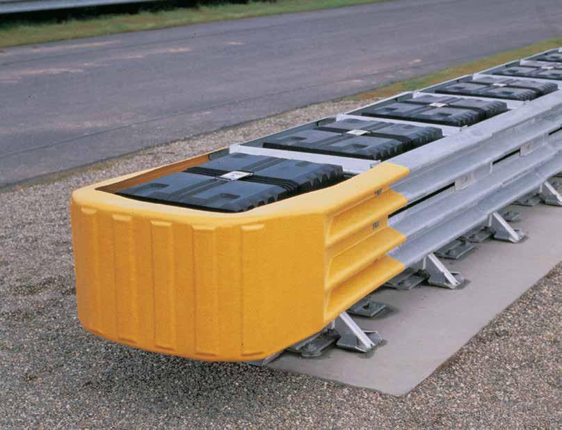
8 After an impact occurs, the debris from the impact should be removed from the area immediately and the specified highway product should be evaluated and restored to its original specified condition or replaced as the highway authority determines as soon as possible. System Overview The QuadGuard is a potentially reusable, redirective, non-gating crash cushion for roadside obstacles ranging in width from 610 mm to 3200 mm (24" to 126"). It consists of energyabsorbing cartridges surrounded by a framework of Quad-Beam TM Panels. Again, the decision as to whether this product is reusable after impact rests within the sound discretion of the trained engineer, experienced in highway products, who is working at the direction of the local DOT, or appropriate highway authority, which specified and now owns the product. The QuadGuard system utilizes two types of cartridges in a staged configuration to address both lighter cars and heavier, high center-of-gravity vehicles. Its modular design allows the system length to be tailored to the design speed of a site. See the QuadGuard Product Manual to determine the appropriate number of Bays for a given speed. Impact Performance The 6 Bay QuadGuard systems have successfully passed the requirements stipulated in NCHRP Report 350, Test Level 3 tests with both the light car and pickup at speeds of up to 100 km/h [62 mph] at angles up to 20 degrees. During head-on impact testing, within NCHRP Report 350 criteria, the QuadGuard has been shown to telescope rearward to absorb the energy of impact. When impacted from the side it has shown that it redirects the vehicle back toward its original travel path and away from the roadside obstacle, when that impact occurs within NCHRP Report 350 criteria. 7 All rights in copyright reserved
9 Recommended Tools Documentation Manufacturer s Assembly Manual Manufacturer s Drawing Package Cutting equipment Rotary Hammer Drill Rebar cutting bit Concrete drill bits 22 mm [7/8 ] (*Double-Fluted) Grinder, Hacksaw or Cutting Torch Drill bits 1/16 through 7/8 Trinity Highway recommends using double-fluted drill bits to achieve optimum tensile strength when applying the MP-3 anchoring system. Hammers Sledgehammer Standard hammer Wrenches Heavy duty 1/2" drive impact wrench Standard adjustable wrench 1/2" drive impact sockets: 9/16", 11/16", 3/4", 15/16", 1 1/8", 1 1/4" 1/2" drive Deep well sockets: 15/16", 1 1/4" 1/2" drive Ratchet and attachments 1/2" drive Breaker bar - 24" long 1/2" drive Torque wrench: 200 ft-lb Allen wrench: 3/8 Personal Protective equipment Safety Glasses Gloves Safety-toe shoes Apron for MP-3 application 8 All rights in copyright reserved
10 Miscellaneous Traffic control equipment Lifting and moving equipment (A lifting device is preferred although a forklift can be used.) Minimum 5,000 lb. capacity required. Air Compressor (100 psi minimum) and Generator (5 kw) Long pry bar Drift pin 300 mm [12 ] Center punch Tape measure 7.5 m [25 ] Chalk line Concrete marking pencil Nylon bottle brush for cleaning 7/8 drilled holes Rags, water, and solvent for touch-up Note: The above list of tools is a general recommendation. Depending on specific site conditions and the complexity of the assembly specified by the appropriate highway authority, additional or fewer tools may be required. Decisions as to what tools are needed to perform the job are entirely within the discretion of the specifying highway authority and the authority s selected contractor performing the assembly of the system at the authority s specified site. 9 All rights in copyright reserved
11 System Identification QuadGuard System for Narrow Roadside Obstacles 610 mm [24 ] Model No. QS mm [30 ] Model No. QS mm [36 ] Model No. QS mm [48 ] Model No. QS48 QuadGuard System for Wide Roadside Obstacles 1755 mm [69 ] Model No. QS m [19-1 ] 2285 mm [90 ] Model No. QS m [22-1 ] 3200 mm [126 ] Model No. QS126 (Min. 6 bays required) Figure 1 Plans & Elevation (Six Bay systems with Tension Strut Backups shown) 10 All rights in copyright reserved
12 How to Determine Left/Right To determine left from right when ordering parts, stand in front of the system facing the roadside obstacle. Your left is the system s left and your right is the system s right. Counting the Number of Bays One Bay consists of one Cartridge, one Diaphragm, two Fender Panels, etc. The Nose section is not considered a Bay, though there is a Cartridge in the Nose of each system. Note that this means there will always be one more Cartridge in the system than the number of Bays in the system. To determine number of Bays, count Fender Panels on one side (see Figure 2). The Five-Bay system is shown. Figure 2 System Orientation 11 All rights in copyright reserved
![Measuring the Width The QuadGuard system is available in five nominal widths: 610 mm [24 ] 760 mm [30 ] 915 mm [36 ] 1219 mm [48 ] 1755 mm [69 ] 2285 mm [90 ]](/docs-images/75/72917310/images/13-0.jpg "3200 mm [126 ] The nominal width of a parallel system is the width of the diaphragm (see Figure 3).")

13 Measuring the Width The QuadGuard system is available in five nominal widths: 610 mm [24 ] 760 mm [30 ] 915 mm [36 ] 1219 mm [48 ] 1755 mm [69 ] 2285 mm [90 ] 3200 mm [126 ] The nominal width of a parallel system is the width of the diaphragm (see Figure 3). The nominal width of a wide system is the width at the location shown in Figure 4. The outside width of the system is approximately 150 mm [6 ] to 230 mm [9 ] wider than the nominal width. The width of the system is not the same as the width of the Backup. Figure 3 Width of Parallel system Figure 4 Width of wide system 12 All rights in copyright reserved
14 Narrow Systems 610 mm [24 ] Model No. QS mm [30 ] Model No. QS mm [36 ] Model No. QS mm [48 ] Model No. QS48 Figure 5 Narrow System and Model Numbers 13 All rights in copyright reserved
15 Site Preparation/Foundation A QuadGuard should be assembled only on an existing or freshly placed and cured concrete base (28 MPa [4000 psi] minimum). Location and orientation of the concrete base and attenuator must comply with project plans or as otherwise determined by the resident project engineer. Recommended dimension and reinforcement specifications for new concrete foundations are provided in Trinity Highway concrete foundation drawings, supplied with the system. The system may be assembled on a non-reinforced concrete roadway (minimum 200 mm [8 ] thick). Deployment cross-slope shall not exceed 8% and should not twist more than 2% over the length of the system; the foundation surface shall have a light broom finish. Caution: Accurate placement of all steel rebar is critical to avoid interference with the concrete anchor bolts. Figure 6 Cross-Slope Warning: Location of the Backup in relation to nearby objects will affect the operation of the attenuator. Upon impact, the Fender Panels telescope rearward and extend beyond the rigid Backup as much as 876 mm [34.5 ]. Position the Backup so that the rear ends of the last Fender Panels are a minimum of 760 mm [30 ] forward of objects that would otherwise interfere with movement of the rearmost Fender Panels. Failure to comply with this requirement will result in impaired system performance offering motorists less protection and causing component damage All rights in copyright reserved
16 Assembly Procedures Inspect Shipping Before deploying the QuadGuard system, check the received parts against the shipping list supplied with the system. Make sure all parts have been received. Assembly Procedures Important: The Drawing Package supplied with the QuadGuard system must be used with these instructions for proper assembly and should take precedence over these general instructions. 1) Determine Backup & Transition Type The QuadGuard system is available with a Tension Strut Backup or a Concrete Backup. See Figure 7 and 8, along with the Backup Assembly drawing, to determine which type of Backup is being deployed. A Transition Panel or Side Panel must be used on each side of the Backup. A Side Panel is not needed when a Transition Panel is used. Several types of Transitions are available for use with the QuadGuard system. See Figures 9 through 14 and the Drawing Package to determine which type of Panels to attach. Figure 7 Tension Strut Backup Figure 8 Concrete Backup Figure 9 Transitioning the QuadGuard System 15 All rights in copyright reserved
17 Transition Panel Types Note: The proper Transition Panel or Side Panel must be used for proper impact performance of the system. The correct Panel(s) to use will depend on the direction of traffic and what type of barrier or roadside obstacle the QuadGuard system is shielding. Contact the Customer Service Department prior to deployment if you have any questions. Figure 10 No Transition Figure 11 Quad-Beam to Safety Shape Barrier Transition Panel Figure 12 Quad-Beam to Thrie-Beam Transition Panel Figure 13 Quad-Beam to W-Beam Transition Panel Figure 14 Quad-Beam End Shoe Transition Panel 16 All rights in copyright reserved
18 2) Mark System Location Locate the centerline of the system by measuring the proper offset from the roadside obstacle. See the Drawing Package supplied with the system. Place chalk line to mark the centerline of the system. Mark a construction line parallel to the center line and offset 165 mm [6.5 ] to one side as shown in Figure 15. The edge of the Monorail will be positioned on this line. Note: The concrete foundation shall comply with the project plans supplied with the system. Warning: Location of system with respect to the roadside obstacle is critical and dependent on the type of Transition Panel used. See the Project Plans supplied with the system for details. Figure 15 (Top view of concrete foundation) 17 All rights in copyright reserved

19 3) Anchor the Backup A) Concrete Backup Construction (Figure 16) Locate Backup Face Plate using the Backup Assembly drawing. Verify that any applicable Transition Panels fit properly before anchoring the Face Plate. Drill anchor holes in the Concrete Backup using the Face Plate as a template. Anchor the Face Plate to the Concrete Backup using the MP-3 Anchoring system (horizontal kit) supplied with the QuadGuard system (see MP-3 Polyester Anchoring System section on page 56). Warning: Every hole and slot in Backup and Monorail must be anchored by an MP-3 stud. B) Tension Strut Backup Assembly (Figure 17) Locate Tension Strut Backup and Monorail on foundation with side of Monorail on the construction line (see Figure 20 on p. 20). Verify that any applicable Transition Panels fit properly before anchoring Backup. Drill anchor holes in foundation using the Backup as template. Anchor the Backup to the concrete foundation using the MP-3 Anchoring system (Horizontal kit) supplied with the QuadGuard system (see MP-3 Polyester Anchoring System section on p. 56). Warning: Every hole and slot in Backup and Monorail must be anchored by an MP-3 stud. Figure 16 Anchoring Backup Face Plate to Concrete Backup Figure 17 Anchoring Tension Strut Backup to Foundation 18 All rights in copyright reserved
20 4) Anchor the Monorail A) Monorail Assembly for Concrete Backup (Figure 19) Locate Monorail on foundation with side of Monorail on the construction line and rear edge of Monorail foot 10 forward of front face of Concrete Backup (see Figure 18). Orient the Monorail so that the Monorail tongues face Backup (see Figure 18). Drill 140 mm [5 1/2"] deep anchor holes using the Monorail as a template. Do not drill through foundation. Warning: Every hole and slot in Backup and Monorail must be anchored by an MP-3 stud. Anchor each Monorail section using the MP-3 vertical kits provided. See Figure 19 and the MP-3 Polyester Anchoring System Instructions included with this Manual. It is important to attach each segment of Monorail in alignment from the back to the front of the system (± 6 mm [1/4 ]). Warning: Improper alignment at the Monorail Sections will prevent proper system collapse during impact. Figure 18 Monorail Location for Concrete Backup MP-3 Anchor WASHER NUT CAUTION: 40 MM [1.5 ] MAXIMUM STUD HEIGHT ROADWAY BACKUP OR MONORAIL Figure 19 Proper Stud Height 19 All rights in copyright reserved
21 B) Monorail Assembly for Tension Strut Backup (Figure 20) Locate Monorail on foundation with side of Monorail on the construction line and rear edge of Backup foot 4 forward of edge of foundation (see Figure 20). Drill 140 mm [5 1/2"] deep anchor holes using the Monorail as a template. Do not drill through foundation. Warning: Every hole and slot in Backup and Monorail must be anchored by an MP-3 stud. Anchor each Monorail section using the MP-3 vertical kits provided. See Detail 20a and the MP-3 Polyester Anchoring System Instructions included with this Manual. It is important to attach each segment of Monorail in alignment from the back to the front of the system (± 6 mm [1/4 ]). Warning: Improper alignment at the Monorail splice joints will prevent proper system collapse during impact. Figure 20 Backup and Monorail Location for Tension Strut Backup Detail 20a Proper Stud Height 20 All rights in copyright reserved
22 5) Attach Side Panels and/or Transition Panels to Backup Assembly Attach Transition Panel or Side Panel to side of Backup using 5/8 rail bolt and 5/8 rail nut (two places - top and bottom holes only). See Figure 21 and Backup Assembly drawing. Note: A Side Panel is not needed when a Transition Panel is used. Assembly tip: Use drift pin to align the center hole of the Panel with the center hole of the Backup before inserting the rail bolts. NARROW SIDE PANEL Figure 21 Side Panel/Transition Panel Attachment 21 All rights in copyright reserved
23 6) Attach Monorail Guides Attach Monorail guides to Diaphragm as shown in Figure 22: Insert 3/4" x 2 G8 hex bolt through Monorail guide and Diaphragm, oriented as shown in Figure 22. Secure with 3/4" lock washer and 3/4" hex nut (typical 4 places). See also Diaphragm Assembly drawing. Repeat process for each Diaphragm. 7) Attach Diaphragms Orient a Diaphragm so that the front face of the Diaphragm shape faces toward the Nose of the system as shown in Figure 23. Slide one Diaphragm all the way to the Backup to ensure the system is able to collapse properly during impact. Once this has been verified, slide the Diaphragm forward to approximately 915 mm [36 ] in front of the Backup. Orient and slide all other Diaphragms onto Monorail and position each approximately as shown in Figure 24. Figure 22 Monorail Guide Attachment Figure 23 Diaphragm Orientation Figure 24 Diaphragm Spacing 22 All rights in copyright reserved
24 8) Attach Fender Panels Note: Do not mix the 5/8 rail nuts (large) with the 5/8 hex nuts (small) (see Figure 25). Figure 25 Rail Nuts are Oversize Starting at the Backup, attach left and right Fender Panels shown on page 24 and Fender Panel Assembly drawing. Step 1 Place the Fender Panel so that the center of the slot of the rearward Diaphragm is lined up with the approximate center of the slot in the Fender Panel. Attach Mushroom Washer Assembly as shown in Figure 26 and Detail 26a and Detail 26b but do not torque at this time. (This helps to balance the Fender Panel.) Step 2 Slide the Fender Panel forward until the holes in the Fender Panel line up with the holes in the forward Diaphragm. Step 3 Use a drift pin to align the center hole of the Fender Panel with the center hole of the Diaphragm. Step 4 Attach the front of the Fender Panels to the next Diaphragm using two (2) rail bolts and large hex rail nuts per side. Use only the top and bottom holes; leave the center hole open until the next Fender Panel is attached All rights in copyright reserved
25 Figure 26 Fender Panel Assembly Step 5 Be sure Mushroom Washer lays flat against the Fender Panel as shown in Figure 26b. Standoff on Mushroom Washer must be seated completely through slot. Detail 26a Mushroom Washer Attachment Detail 26b Mushroom Washer Orientation 24 All rights in copyright reserved
26 Step 6 Check Diaphragm spacing to ensure 915 mm [36 ] between rear faces of consecutive Diaphragms as shown in Figure 27 and Fender Panel Assembly drawing. Step 7 Once proper spacing has been achieved, torque the Mushroom Washer Assembly (small hex) nut until it reaches the end of the threads. Assemble the remaining Diaphragms and Fender Panels following the same procedures. Figure 27 Proper Spacing Between Diaphragms 25 All rights in copyright reserved
27 9) Attach End Cap Using 5/8 x 3 1/2" G5 hex bolt, 5/8 hex nut and 5/8 lock washer, attach the End Cap to the front of the first Monorail segment, as shown in Figure 28 and Monorail Assembly drawing. Figure 28 Monorail End Cap Assembly 10) Attach Cartridge Support Brackets Attach lower Cartridge Support Bracket to front and back of all Diaphragms and front of Backup as shown in Figures 30 to 32, the Diaphragm Assembly drawings and the Backup Assembly drawings (see p. 27). Note: 610 mm [24 ] wide systems do not have Side Cartridge Support Brackets: 762 mm [30 ], 914 mm [36 ] and 1219 mm [48 ] wide systems have Side Cartridge Support Brackets welded to the Backup and Diaphragms. Figure 29 Side Cartridge Support Brackets 26 All rights in copyright reserved
28 Figure 30 Lower Cartridge Support Bracket Assembly INSERT INSERT Figure 31 Lower Cartridge Support Bracket Assembly (Tension Strut Backup) Figure 32 Lower Cartridge Support Bracket (Concrete Backup) 27 All rights in copyright reserved

29 11a) Attach Plastic Nose Assembly Determine which style of Cartridges your system has. If your system has Cartridge style A as shown in Figure 33, attach Cartridge Support in the upper two slots as shown. If your system has Cartridge style B as shown in Figure 33, attach Cartridge Support in the lower two slots as shown. Figure 33 Adjustable Bracket Locations 28 All rights in copyright reserved


30 As shown in Detail 33a, Cartridge Style A is attached with the Adjustable Support Bracket incorrectly in the lower position. Detail 33a Incorrect Attachment of Adjustable Cartridge Support Bracket As shown in Detail 33b, Cartridge Style B is attached with the Adjustable Cartridge Support Bracket incorrectly in the upper position. Detail 33b Incorrect Attachment of Adjustable Cartridge Support Bracket Detail 33c shows the Adjustable Cartridge Support Bracket attached correctly. Detail 33c Correct Attachment of Adjustable Cartridge Support Bracket 29 All rights in copyright reserved
31 Bolt the Nose Assembly directly to the Front Diaphragm, as shown in Detail 33d and the Nose Assembly drawings, using six (6) rail bolts which also hold the front two Fender Panels to the Diaphragm with Bar Washer under each bolt. Place Pullout Brackets under center nuts. The top and bottom holes of the Nose are slotted to provide adjustment. Adjust so the top edge of the Nose is level with the top edge of the Fender Panels and then torque all six (6) nuts to 35 N-m [25 ft-lb]. PULL OUT BRACKET Detail 33d Nose Assembly Detail 33e Adjust Nose 30 All rights in copyright reserved

32 11b) Optional Steel Nose Assembly Bolt the Nose directly to the front Diaphragm, as shown in Figures 35, 35a, 35b and the Nose Assembly drawing, using six (6) rail bolts which also hold the front two Fender Panels to the Diaphragm with Bar Washer under each bolt. Place Pullout Brackets under center bolts. SEE DETAILS 35a - 35g Figure 35 STEEL NOSE ASSEMBLY SEE DETAIL 35C (INSIDE VIEW) 5/8 X 1 1/4" HEX SOCKET BOLT 5/8 FLAT WASHER 5/8 COUPLING NUT 5/8 RAIL NUT PULLOUT BRACKET Detail 35a Detail 35b Steel Nose not shown for Clarity 31 All rights in copyright reserved

33 THREAD COUPLING NUT FLUSH WITH OUTSIDE HUMPS ON FENDER PANEL Detail 35c End View with no Nose Cover Detail 35d End View: Nose Cover Cut Away SEE DETAIL 35f FASTEN ALL LOCATIONS WITH 1/4-20 FASTENERS TOTAL SIX 1/4-20 FASTENERS CARTRIDGE SUPPORT BRACKET Detail 35e G BOLT,HX,1/4X3/4,G5,G G WASHER,LOCK,1/4,G G NUT,HX,1/4,G Detail 35f Steel Nose not shown for Clarity Detail 35f shows proper placement of Front Cartridge Support Bracket. Note difference of front Diaphragm Bracket. The Cartridge sits lower on this Bracket than the Bays to the rear. Detail 35g 32 All rights in copyright reserved
34 11c) Optional Belt Nose Assembly a. Using 5/8 x 5 hex bolt, two (2) 5/8 x 1 3/4" flat washers and 5/8 hex nut, attach Fender Panel to front Diaphragm top and bottom as shown in Figure 36 (two places per side). b. Using 5/8 x 5 hex bolt and 5/8 hex nut, attach Pullout Bracket to front Diaphragm and Fender Panel middle as shown (one place per side). c. Thread second 5/8 nuts onto the attached bolts. Be sure the faces of the nuts are flush with humps on Fender Panels (see Figure 36). Slide third 5/8 x 1 3/4 flat washers onto bolts (three places per side). d. Align holes in each end of the Nose Belt with the attached bolts (three per side) and slide Nose Belt onto bolts. e. Align holes in Belt Clamps with bolts and slide Belt Clamps onto bolts. f. Using fourth 5/8 x 1 3/4" flat washer and third 5/8 hex nut, secure the Belt Clamps and Nose Belt (three places per side). Refer also to Nose Belt Assembly drawing. Note: Nose alignment shown in Figure 33e not necessary with Nose Belt Assembly (see p. 30). 5/8 HEX NUT 5/8 X 1 3/4" FLAT WASHER FRONT DIAPHRAGM QG NOSE BELT 5/8 X 1 3/4" FLAT WASHER 5/8 X 5" G5 ALL THREAD HEX BOLT BELT CLAMP FACE OF THE NUT TO BE FLUSH WITH HUMPS ON FENDER PANEL 5/8 X 1 3/4" FLAT WASHER 5/8 HEX NUT Figure 36 Optional Nose Belt Assembly Note: Nose of system may be delineated to comply with local codes (chevron, reflective material, signs, etc. supplied by others) All rights in copyright reserved
35 12) Checking the System Assembly At this point recheck to ensure that all fasteners are properly tightened throughout the system (anchor bolts, etc.). See warning below. Check all Fender Panels. If they do not fit tightly against the underlying Panel, system realignment may be necessary (see Detail 26a & 26b). Warning: Bolt Torque Requirements Anchor Studs see Table A, p. 56 May slightly protrude above nuts Critical Clearances Anchor Studs above nuts see Figure 19, p. 19 Fender Panel Gap Narrow 20 mm [0.78 ] see below Figure 37 Fender Panel Gap for Narrow Systems 13) Cartridge Assembly Be sure the Adjustable Cartridge Support in the Nose is attached correctly. See Attach Nose Assembly in Step 11 on page 28. The top surface of the Nose Cartridge should be horizontal. To complete the assembly of a QuadGuard system, place the appropriate Cartridge in each Bay and Nose section of the system. Type 1 Cartridges are placed toward the front (Nose) of the system; Type II Cartridges are placed toward the rear (Backup) of the system (see Figures 38 and 39). Warning: Placing the wrong Cartridge in the Nose or any Bay is strictly prohibited pursuant to NCHRP Report 350 testing criteria. Such configurations have not been accepted for use and may result in unacceptable crash performance All rights in copyright reserved
36 Figure 38 Cartridge Placement Figure 39 Typical Cartridge Layout 5 Bay System Shown 35 All rights in copyright reserved
37 Wide Systems Figure 40 Wide Systems and Model Numbers 36 All rights in copyright reserved
38 Site Preparation/Foundation A QuadGuard system should be constructed only on an existing or freshly placed and cured concrete base (28 MPa [4000 psi] minimum). Location and orientation of the concrete base and attenuator must comply with project plans or as otherwise determined by the resident project engineer. Recommended dimension and reinforcement specifications for new concrete foundations are provided in Trinity Highway concrete foundation drawings, supplied with the system. The system may be assembled on a non-reinforced concrete roadway (minimum 200 mm [8 ] thick). Deployment cross-slope shall not exceed 8% and should not twist more than 2% over the length of the system; the foundation surface shall have a light broom finish. Caution: Accurate placement of all steel rebar is critical to avoid interference with the concrete anchor bolts. Warning: Location of the Backup in relation to nearby objects will affect the operation of the attenuator. Upon impact, the Fender Panels telescope rearward and extend beyond the rigid Backup as much as 876 mm [34.5 ]. Position the Backup so that the rear ends of the last Fender Panels are a minimum of 760 mm [30 ] forward of objects that would otherwise interfere with movement of the rearmost Fender Panels. Failure to comply with this requirement will result in impaired system performance offering motorists less protection and cause component damage. Inspect Shipping Before deploying the QuadGuard system, check the received parts against the shipping list supplied with the system. Make sure all the parts have been received. Assembly Procedures Caution: The Drawing Package supplied with the QuadGuard system must be used with these instructions for proper assembly and should take precedence over these general instructions. 1) Determine Backup and Transition Type The QuadGuard is available with a Tension Strut Backup or a Concrete Backup. See Figures 41 and 42, along with the Backup assembly drawing, to determine which type of Backup is being deployed. A Transition Panel or Side Panel must be used on each side of the Backup. A Side Panel is not needed when a Transition Panel is used. Several types of transitions are available for use with the QuadGuard system. See Figures 43 through 48 and the drawing package to determine which types of panels to attach All rights in copyright reserved
39 Figure 41 Tension Strut Backup Figure 42 Concrete Backup Figure 43 Transitioning the QuadGuard System 38 All rights in copyright reserved


40 Transition Panel Types Note: The proper Transition Panel or Side Panel must be used for impact performance of the system. The correct Panel(s) to use will depend on the direction of traffic and what type of barrier or roadside feature the QuadGuard system is shielding. Contact the Customer Service Department prior to deployment if you have any questions. Arrows indicate traffic direction. Figure 44 No Transition Note: Arrows indicate traffic direction. Figure 45 Quad-Beam to Safety Shape Barrier Figure 46 Quad-Beam to Thrie-Beam Figure 47 Quad-Beam to W-Beam Note: Arrows indicate traffic direction. Figure 48 Quad-Beam End Shoe 39 All rights in copyright reserved
41 2) Mark System Location Locate the centerline of the system by measuring the proper offset from the roadside obstacle. See the Drawing Package supplied with the system. Place chalk line to mark the centerline of the system. Mark a construction line parallel to the center line and offset 165 mm [6.5 ] to one side as shown in Figure 49. The edge of the Monorail will be placed on this line. Note: The concrete foundation shall comply with the project plans supplied with the system. Warning: Location of system with respect to the roadside obstacle is critical and dependent on the type of Transition Panel used. See the Project Plans supplied with the system for details. Figure 49 (Top view of concrete foundation) 3) Anchor the Backup A) Concrete Backup Construction (Figure 50) Locate Backup Face Plate using the Backup assembly drawing. Verify that any applicable Transition Panels fit properly before anchoring the Face Plate. Drill anchor holes in the Concrete Backup using the Face Plate as a template. Anchor the Face Plate to the Concrete Backup using the MP-3 Anchoring system (horizontal kit) supplied with the QuadGuard system (see MP-3 Polyester Anchoring System section on p. 56). Warning: Every hole and slot in Backup and Monorail must be anchored by an MP-3 stud. Figure 50 Anchoring Backup Face Plate to Concrete Backup 40 All rights in copyright reserved
42 B) Monorail Assembly for Tension Strut Backup Locate the Tension Strut Backup on foundation with side of Monorail on the construction line (see Figure 55 on page 44). Verify that any applicable Transition Panels fit properly before anchoring Backup. Drill anchor holes in foundation using the Backup as template. Anchor the Backup to the concrete foundation using the MP-3 Anchoring System (vertical kit) supplied with the QuadGuard system (see MP-3 Polyester Anchoring System section on p. 56). Warning: Every hole and slot in Backup and Monorail must be anchored by an MP-3 stud. Figure 51 Anchoring Tension Strut Backup to Foundation 41 All rights in copyright reserved
43 C) Extra-Wide Tension Strut Backup Assembly (Figure 52) Locate the Extra-Wide Tension Strut Backup center section and Monorail on foundation with side of Monorail on the construction line (see Figure 55 on p.44). Locate the Extra-Wide Tension Strut Backup left section on the left side of the center section, aligning the three holes in the side plates. Locate the Extra-Wide Tension Strut Backup right section on the right side of the center section, aligning the three holes in the side plates. Secure the Backup sections to each other using 5/8 x 2 hex bolt, 5/8 x 1 3/4" flat washer (2), 5/8 lock washer and 5/8 hex nut (6 places) as shown in Figure 52 and Detail 52a. Verify that any applicable Transition Panels fit properly before anchoring Backup. Drill anchor holes in foundation using the Backup as template. Anchor the Backup to the foundation using the MP-3 vertical kits supplied with the QuadGuard system (see MP-3 Polyester Anchoring System on page 56). Warning: Every hole and slot in Backup and Monorail must be anchored by an MP-3 stud. 52a Figure 52 Anchoring Extra-Wide Tension Strut Backup to Foundation See Drawing Package Detail 52a 42 All rights in copyright reserved
44 4) Anchor the Monorail A) Monorail Assembly for Concrete Backup (see Figure 54). Locate Monorail on foundation with side of Monorail on the construction line and rear edge of Monorail foot forward of front face of Concrete Backup (see Figure 53). Orient the Monorail so that the Monorail tongues face Backup (see Figure 53). Drill 140 mm [5 1/2"] deep anchor holes using the Monorail as a template. Do not drill through foundation. Warning: Every hole and slot in Backup and Monorail must be anchored by an MP-3 stud. Anchor each Monorail section using the MP-3 vertical kits provided. See Figure 19 and the MP-3 Polyester Anchoring System Instructions included with this Manual. It is important to attach each segment of Monorail in alignment from the back to the front of the system (± 6 mm [1/4 ]). Warning: Improper alignment at the Monorail Splice Joints will prevent proper system collapse during an impact. Figure 53 Monorail Location for Concrete Backup MP-3 Anchor WASHER NUT CAUTION: 40 MM [1.5 ] MAXIMUM STUD HEIGHT ROADWAY Figure 54 Proper Stud Height BACKUP OR MONORAIL 43 All rights in copyright reserved
45 B) Monorail Assembly for Tension Strut Backup (see Figure 55). Locate Monorail on foundation with side of Monorail on the construction line and rear edge of Backup foot 4 forward of edge of foundation (see Figure 55). Drill 140 mm [5 1/2"] deep anchor holes using the Monorail as a template. Do not drill through foundation. Warning: Every hole and slot in Backup and Monorail must be anchored by an MP-3 stud. TONGUE Figure 55 Backup and Monorail Location for Tension Strut Backup Detail 55a Proper Stud Height 5) Attach Side Panels and/or Transition Panels to Backup Assembly (see Figure 56). a. Attach Hinge Plate to the Transition Panel or Side Panel using 5/8 rail bolt and 5/8 rail nut (two places top and bottom holes only). b. Attach Transition Panel or Side Panel assembly to side of Backup using 5/8 x 4 hex bolt, 5/8 lock washer and 5/8 hex nut at three places on each side of Backup (see Figure 56). c. Attach diagonal brace to Fender Panel and Backup using 3/8 hex bolt, 3/8 lock washer and 3/8 hex nut (two places per brace: 4 places per side). d. Secure each diagonal brace with 3/8 hex bolt, 3/8 lock washer, and 3/8 hex nut (two places per brace) as shown in Figure 56. Note: A Side Panel is not needed when a Transition Panel is used. Diagonal braces not used with some Transition Panels. See drawing package All rights in copyright reserved
46 Assembly tip: Use drift pin to align the center hole of the Panel with the center hole of the Backup before attaching the rail bolts. TENSION STRUT BACKUP CONCRETE BACKUP 3/8 X 3 1/2" HEX BOLT DIAGONAL BRACE (INNER) 3/8 LOCK WASHER 5/8 X 4" HEX BOLT 3/8 HEX NUT DIAGONAL BRACE (OUTER) 3/8 X 3 1/2" HEX BOLT WIDE SIDE PANEL HINGE PLATE 3/8 LOCK WASHER 3/8 HEX NUT 5/8 RAIL BOLT Figure 56 Side Panel/Transition Panel Attachment 5/8 LOCK WASHER 5/8 HEX NUT (SMALL) 5/8 RAIL NUT (LARGE) (SEE FIGURE 60) 45 All rights in copyright reserved
47 6) Attach Monorail Guides Attach Monorail guides to Diaphragm as shown in Figure57: Insert 3/4" x 2 G8 hex bolt through Monorail guide and Diaphragm, oriented as shown in Figure 57. Secure with 3/4" lock washer and 3/4" hex nut (typical two places per guide). See also Diaphragm assembly drawing. Shims are sandwiched between Monorail guides and Diaphragm. Repeat process for each Diaphragm. DIAPHRAGM 3/4" HEX NUT 3/4" LOCK WASHER MONORAIL GUIDE 3/4" X 2 GR8 HEX BOLT Figure 57 Monorail Guide Attachment 46 All rights in copyright reserved
48 7) Attach Diaphragms Orient the widest Diaphragm so that the front face of the Diaphragm shape faces toward the Nose of the system as shown in Figure 58. The widest Diaphragm must be attached closest to the Backup with each subsequent Diaphragm being progressively narrower. Slide the widest Diaphragm onto the Monorail and all the way to the Backup to ensure system is able to collapse properly during impact. Once this has been verified, slide the Diaphragm forward to approximately 915 mm [36 ] in front of the Backup. Orient and slide all other Diaphragms onto Monorail and position each approximately as shown in Figure 59. Figure 58 Diaphragm Orientation 915 mm [36 ] Bay 3 & Higher 3 rd Diaphragm 2 nd Diaphragm 1 st Diaphragm Bay 3 Bay 2 Bay 1 Nose Figure 59 Diaphragm spacing 47 All rights in copyright reserved
49 8) Attach Hinge Plate onto Fender Panels Note: Do not mix the 5/8 rail nuts (large) with the 5/8 hex nuts (small) (see Figure 60). Figure 60 Rail Nuts are Oversize Note: For proper impact performance, wide systems must use Hinge Plates. Attach Hinge Plate on each Fender Panel using two (2) 5/8 rail bolts and two (2) 5/8 rail nuts, using top and bottom holes only, leaving the center-hole open as shown in Figure 61. 9) Attach Fender Panels Figure 61 Hinge Plate Assembly Starting at the Backup, attach left and right Fender Panels as shown in Figure 62 and Fender Panel Assembly drawing. Step 1 Place the Fender Panel so that the center of the slot of the rearward Diaphragm is lined up with the approximate center of the slot in the Fender Panel. Attach Mushroom Washer Assembly as shown in Figure 62, Detail 62a and Detail 62b, but do not torque at this time (this helps to balance the Fender Panel) All rights in copyright reserved
50 Step 2 Slide the Fender Panel forward until the holes in the Fender Panel line up with the holes in the forward Diaphragm. Step 3 Use a drift pin to align the center hole of the Fender Panel with the center hole of the Diaphragm. Step 4 Attach the front of the Fender Panels to the next Diaphragm using two (2) rail bolts and large hex nuts per side. Use only the top and bottom holes; leave the center hole open until the next Fender Panel is attached. Step 5 Be sure Mushroom Washer lays flat against the Fender Panel as shown in Detail 62a. Standoff on Mushroom Washer must be seated completely through slot. Figure 62 Fender Panel Assembly 49 All rights in copyright reserved
51 Detail 62a Mushroom Washer Orientation 18 mm [11/16] ROUND HOLE LONG SLOT IN FENDER PANEL DIAPHRAGM OR BACKUP 5/8" RAIL NUT (LARGE) 1 1/2" DIE SPRING MUSHROOM WASHER QUAD-BEAM FENDER PANEL HINGE PLATE PANEL ALREADY ATTACHED TO DIAPHRAGM OR BACKUP Detail 62b Mushroom Washer Attachment 50 All rights in copyright reserved
52 Step 6 Check Diaphragm spacing to ensure 915 mm [36 ] between rear faces of consecutive Diaphragms as shown in Figure 63 and Fender Panel Assembly drawing. Step 7 Once the proper spacing has been achieved, torque the Mushroom Washer Assembly (small hex nut) until it reaches the end of the threads. Assemble the remaining Diaphragms and Fender Panels following the same procedures. DIAPHRAGM OR BACKUP BAY SPACING 915 mm [36 ] FENDER PANEL DIAPHRAGM Figure 63 Proper Spacing Between Diaphragms 10) Attach End Cap Using 5/8 x 3 1/2 G5 hex bolt, 5/8 hex nut and 5/8 lock washer, attach the End Cap to the front of the first Monorail segment as shown in Figure 64 and the Monorail Assembly drawing. Figure 64 Monorail End Cap Assembly 51 All rights in copyright reserved
53 11) Assemble Cartridge Support Brackets Attach lower Cartridge Support Bracket to front and back of all Diaphragms and front of Backup as shown in Figures 65, 66, 67 and 68, the Backup Assembly drawing and the Diaphragm Assembly drawing. Figure 65 Diaphragm with Cartridge Support Bracket STEP I INSERT LOWER CARTRIDGE SUPPORT BRACKET CARTRIDGE SUPPORT BRACKET CONCRETE BACKUP FACE PLATE STEP II INSERT KEEPER CARTRIDGE SUPPORT BRACKET Figure 66 Cartridge Support Bracket (Tension Strut Backup) Figure 67 Cartridge Support Bracket (Concrete Backup) 52 All rights in copyright reserved
54 Figure 68 Extra-Wide First Diaphragm With Cartridge Support Bracket (see Drawing Package) 12) Attach Nose Assembly See pages for Nose Assembly information. 13) Checking the System Assembly At this point recheck to ensure that all fasteners are properly tightened throughout the system (anchor bolts, etc.). See warning below. Check all Fender Panels. If they do not fit tightly against the underlying Fender Panels, system realignment may be necessary (see Figure 69). Warning: Bolt Torque Requirements Anchor Studs see Table A, p. 56 May slightly protrude above nuts Critical Clearances Anchor Studs above nuts see Figure 18, p. 19 Fender Panel Gap Wide 25 mm [1.00 ] see below Figure 69 Fender Panel Gap for Wide Systems 53 All rights in copyright reserved
55 14) Cartridge Attachment Be sure the Adjustable Cartridge Support in the Nose is attached correctly. See Attach Nose Assembly in Step 11a on page 28. The top surface of the Nose Cartridge should be horizontal. To complete the assembly of a QuadGuard system, place the appropriate Cartridge in each Bay and Nose section of the system. Type I Cartridges are placed toward the front (Nose) of the system; Type II Cartridges are placed toward the rear (Backup) of the system (see Figures 70 and 71). Warning: Placing the wrong Cartridge in the Nose or any Bay is strictly prohibited pursuant to NCHRP Report 350 testing criteria. Such configurations have not been accepted for use and may result in unacceptable crash performance. Figure 70 Cartridge Placement 54 All rights in copyright reserved
56 Figure 71 Typical Cartridge Layout (6 Bay System Shown) 55 All rights in copyright reserved

57 MP-3 Polyester Anchoring system The MP-3 Polyester Anchoring System is a quick and easy way to securely anchor crash cushions and other common highway devices. MP-3 features high pullout strength, superior vibration resistance, and exceptional durability. Each MP-3 kit contains a can of MP-3 resin, hardener, cold weather promoter, studs, nuts, and washers. The cold weather promoter shortens hardening time by as much as seven hours. Both vertical and horizontal assemblies are possible using the MP-3 system. Vertical Assemblies Note: Read MP-3 Instructions before starting. 1) Prepare the Concrete Foundation Warning: Do not allow the MP-3 resin or hardener to contact skin or eyes. See MSDS (material safety data sheet) supplied with the MP-3 kit for first-aid procedures. Use only in well-ventilated area. Do not use near open flame. Warning: Wear safety goggles, apron, and gloves during construction. The anchor bolts (studs) that anchor the QuadGuard system Backup and/or Monorail sections to the concrete foundation must be those shipped in the kit or of high strength steel (830 MPa [120,000 psi] minimum tensile strength or equal). These studs must be set in minimum 28 MPa [4000 psi] concrete. Allow the concrete to cure a minimum of seven days before applying MP-3. 2) Drill Holes Note: Trinity Highway recommends using double-fluted drill bits to achieve optimum tensile strength when applying the MP-3 anchoring system. Use the part that is to be anchored as a drilling template. Drill the holes 3 mm [1/8 ] larger than the stud diameter to the recommended depth, using a rotary hammer drill. If a diamond drill bit is used, the surface will be too smooth for the MP-3 to adhere and full strength will not be achieved. See the MP-3 assembly instructions provided with your kit. Check to be sure all the holes are drilled to the proper depth and aligned with the part to be anchored (see Table A). Table A MP-3 Anchoring Information Stud Size Concrete Bit Size Minimum Depth Recommended Torque 3/4 x 6 1/2" 22 mm [7/8 ] 125 mm [5 ] 165 N-m [120 ft-lb] 3/4 x 7" 22 mm [7/8 ] 140 mm [5 1/2"] 165 N-m [120 ft-lb] 3/4 x 18" 22 mm [7/8 ] 420 mm [16 1/2 ] 15 N-m [10 ft-lb] Important: When mounting on asphalt, initial torque shall be as shown in Table A. Due to the instability of asphalt, anchors may loosen over time. For this reason Trinity Highway recommends anchoring to asphalt only at temporary locations. It is recommended to re-torque anchors in asphalt every 6 months to the proper initial torque specified All rights in copyright reserved
Installation Manual. QuadGuard System. The World Wide Standard In Crash Cushions ENERGY ABSORPTION
 The World Wide Standard In Crash Cushions ENERGY ABSORPTION SYSTEMS, INC. A Quixote Company Saving Lives By Design Corporate Offices: 35 East Wacker Dr., 11th Floor Chicago, IL 60601-2076 Telephone: (312)
Guardrail End Treatment. Instructional Manual
 SRT -27 AND SRT -31 Guardrail End Treatment Instructional Manual IMPORTANT: These instructions are to be used only in conjunction with the installation of the SRT -27 and SRT -31 systems. These instructions
X-Tension TM Guardrail End Terminal
 Installation and Maintenance Manual X-Tension TM Guardrail End Terminal Step by Step Instructions for the Tangent, Flared and Median Applications Barrier Systems Sales and Service 3333 Vaca Valley Pkwy,
Introduction 3. System Overview 3. Before Installation 3. Limitations and Warnings 4. Safety Statements 4. Parts Identification 5.
 June 2015 Table of Contents Introduction 3 System Overview 3 Before Installation 3 Limitations and Warnings 4 Safety Statements 4 Parts Identification 5 Preparation 7 Soil Conditions 7 Tools Required 7
X-350 Guardrail End Terminal
 X-350 Guardrail End Terminal Tangent and Flared Step by Step Instructions for the Tangent and Flared Applications Ph 0800 655 200 or visit www.csppacific.co.nz August 2011 / Page 1 Table of Contents Introduction
SKT-SP Tangent Terminal
 Assembly Instructions for metric SKT-SP Tangent Terminal & FLEAT-SP Flared Terminal SP Standard Post System Guardrail Terminals ROAD SYSTEMS, INC. P. O. Box 2163 Big Spring, Texas 79721 Phone: (432) 263-2435
X-TENSION 350 Guardrail End Terminal Tangent and Flared
 X-TENSION 350 Guardrail End Terminal Tangent and Flared December 2015 Table of Contents Introduction 3 System Overview 3 Before Installation 3 Limitations and Warnings 4 Safety Statements 4 Parts Identification
Assembly Instructions for. for 31" MGS (Midwest Guardrail System) ROAD SYSTEMS, INC.
 ROAD SYSTEMS, INC.") MSKT Assembly Instructions for MASH Tangent Terminal for 31" MGS (Midwest Guardrail System) ROAD SYSTEMS, INC. P. O. Box 2163 Big Spring, Texas 79721 Phone: (432) 263-2435 FAX: (432) 267-4039 Technical
MSKT Assembly Instructions for MASH Tangent Terminal for 31" MGS (Midwest Guardrail System) ROAD SYSTEMS, INC. P. O. Box 2163 Big Spring, Texas 79721 Phone: (432) 263-2435 FAX: (432) 267-4039 Technical
ABSORB 350 Crash Cushion Product Specifications
 ABSORB 350 Crash Cushion Product Specifications Product Specification: ABSORB 350 TL-2 Non Re-directive, Gating, Crash Cushion Applied to Permanent or Portable Concrete Barrier I. General The ABSORB 350
Installation Manual for Gate Guard
 Installation Manual for Gate Guard Fast Opening Barrier Gate for Emergencies and Contra Flow Innovative safety technology from SGGT of Germany TABLE OF CONTENTS Page Number Preface 3 Introduction 3 System
Terminus TM CEN End Terminal
 Product/Installation Manual Corporate Offices: 35 East Wacker Dr., 11 th Floor Chicago, IL 60601-2076, USA Tel: +1 (312) 467-6750 Fax: +1 (312) 467-1356 http://www.energyabsorption.com/ Quixote Europe
Bumper Sign INSTALLATION INSTRUCTIONS
 Bumper Sign INSTALLATION INSTRUCTIONS BUMPERSIGN TOOL CHECKLIST SDS MAX Rotary Hammer Drill Marker/Pencil SDS MAX 1 Carbide Drill Bit Tape Measure Torque Wrench with ½ Drive Power Source Vacuum ½ Drive
400A 40113V, 401A 40120V, & 401AL 40120VL ALUMINUM VERTICAL 4000 LB LIFT INCLUDES SCREW LEG ASSEMBLY INSTRUCTIONS
 12/11/07 PAGE 1 OF 12 400A 40113V, 401A 40120V, & 401AL 40120VL ALUMINUM VERTICAL 4000 LB LIFT INCLUDES SCREW LEG ASSEMBLY INSTRUCTIONS Thank you for purchasing our product! *Please read these instructions
RBP-1215B-RX DODGE RAM QUAD CAB RX3
 RBP-1215B-RX3 2002-2017 DODGE RAM 15-3500 QUAD CAB RX3 Passenger side RX-3 Side Step Drill Template Passenger side rear Modular Bracket (6) L Support Brackets Driver side rear Modular Bracket Driver side
LC200DS1 Double Stud Articulating Wall Mount for Flat Panel Screens up to 32" with up to 200mm x 200mm VESA Mounting Patterns
 Page 1 of 6 LC200DS1 Double Stud Articulating Wall Mount for Flat Panel Screens up to 32" with up to 200mm x 200mm VESA Mounting Patterns A multi-position dual articulating arm for flat screens up to 60
Installation and Assembly: Flat Video Wall Mount For 40" to 65" Flat Panel Displays
 Installation and Assembly: Flat Video Wall Mount For 40" to 65" Flat Panel Displays Model: DS-VW665 Maximum Load Capacity: 125 lb (57 kg) 1 of 11 ISSUED: 03-22-12 SHEET #: 125-9288-4 06-25-13 NOTE: Read
Straight Stringer Installation Instructions
 Straight Stringer Installation Instructions Floor-to-Wall Installation F L I G H T P L A N Unpack: What s included? Your Stringer Tread Screws (8) per tread (1) Torque Wrench (1) Socket (for the brackets
Highway Care Ltd. Xtension 110 P4 Terminal & Xtension 110 Double Sided P4 Terminal DESIGN, INSTALLATION & MAINTENANCE MANUAL REVISION 1E
 Xtension 110 P4 Terminal & Xtension 110 Double Sided P4 Terminal DESIGN, INSTALLATION & MAINTENANCE MANUAL REVISION 1E Highway Care Limited Page 1 Revision 1E Contents Page Introduction 3 Before Installation
INSTALLATION AND MAINTENANCE MANUAL X-TENSION. NCHRP 350 TL-3 Tangent / Flared End Terminal and Median Attenuator
 INSTALLATION AND MAINTENANCE MANUAL X-TENSION NCHRP 350 TL-3 Tangent / Flared End Terminal and Median Attenuator INSTALLATION AND MAINTENANCE MANUAL Table of Contents Introduction 3 System Overview 3 Before
CONTENTS TOOL LIST U P S I D E I N N O V A T I O N S, L L C RAMP AND STEP SYSTEM ASSEMBLY INSTRUCTIONS. Revised: June 2013
 U P S I D E I N N O V A T I O N S, L L C RAMP AND STEP SYSTEM ASSEMBLY INSTRUCTIONS TOOL LIST Required Tools: - Reciprocating Saw with Metal Cutting Blade - Drill - 7/16 Drill Bit for Metal Drilling -
CAT-350 Product Manual
 CAT-350 Product Manual Release 01/17 www.ingalcivil.co.nz CAT-350 NZ Assembly Manual Ingal Civil Products NZ 40 Tironui Road, Auckland 2112 www.ingalcivil.co.nz Important: These instructions are for standard
PRODUCT: LOKI INSTALLATION INSTRUCTIONS. Product is covered by U.S. patents. For more information visit
 R INSTALLATION INSTRUCTIONS PRODUCT: LOKI CONFIGURATION: SINGLE DOOR MOUNT: GLASS MOUNT Product is covered by U.S. patents. For more information visit www.krownlab.com . TOOLS + MATERIALS REQUIRED TOOLS
INSTALLATION INSTRUCTIONS HEAVY DUTY TILT WALL MOUNT Model: PPH-2000
 INSTALLATION INSTRUCTIONS HEAVY DUTY TILT WALL MOUNT Model: PPH-2000 Specifications: Accomodates Akira and Orion 84" displays without interface bracket; accomodates other large flat panel displays with
Sales & Service. JFK - Just For Kids. sasportonline.com. 135 Forestview Road 7879 Will Rogers Blvd.
 Sales & Service sasportonline.com SA Sport (Canada) SA Sport (U.S.A.) 135 Forestview Road 7879 Will Rogers Blvd. P.O. Box 40 Fort Worth, Texas Orillia, Ontario USA 76140 Canada L3V 6H9 Telephone: (705)
ASSEMBLY AND CARE INSTRUCTIONS JUST FOR KIDS 355
 ASSEMBLY AND CARE INSTRUCTIONS VERSION: 8920100 (Revised 06/16) JUST FOR KIDS 355 SALES AND SERVICE spiethamerica.com Canada and International 135 Forestview Road, PO Box 40 Orillia, Ontario, Canada L3V
GearBoss II High Density storage
 Assembly/Owner s Manual GearBoss II High Density storage contents Safety...........................................2 General......................................2 Installation...................................2
Installation Instructions Kit, Base Rail Bracket Part # 31413
 Installation Instructions Kit, Base Rail Bracket Part # 31413 Dealer / Installer: Provide a copy of these Instructions to the end user of this product. These Instructions provide important operating and
Dual Arm Tilt LCD Mount
 Installation Manual model # 51324 M o u n t i n g S y s t e m s Dual Arm Tilt LCD Mount Fits Displays 13 to 32 Supports Up to 50 lbs (23 kgs) Projection from Wall from 3 to 17 Meets VESA Standards 50/75/100,
NX8 SERIES 6-1/4 HANDRAIL W/ VINYL HANDGRIP
 6-1/4 HANDRAIL W/ VINYL HANDGRIP TYPICAL ASSEMBLY 5 2 BUTT JOINT 12 10 9 1 8 11 6 3 7 4 BUTT JOINT COMPONENT LIST 1 LEFT RETURN 7 UPPER IMPACT ABSORBER 2 RIGHT RETURN 8 LOWER IMPACT ABSORBER 3 OUTSIDE
MTS-SP100. RENOGY Pole Mount System E Philadelphia St, Ontario, CA Version: 1.2
 MTS-SP100 RENOGY Pole Mount System 2775 E Philadelphia St, Ontario, CA 91761 1-800-330-8678 1 Version: 1.2 Important Safety Instructions Please save these instructions. This manual contains important safety,
Installation and Assembly - Universal Articulating Swivel Double-Arm for 42" - 60" Plasma Screens
 Installation and Assembly - Universal Articulating Swivel Double-Arm for 42" - 60" Plasma Screens Models: PLAV 70-UNL, PLAV 70-UNL-S PLAV 70-UNLP, PLAV 70-UNLP-S R This product is UL Listed. It must be
Warnings. Description. Prior to Installation Tools Needed
 Warnings Failure to act in accordance with the following may result in death or personal injury. The JT Strong Arm Stabilizer System is intended to eliminate chassis movement in travel trailers and fifth
Installation and Assembly - Universal Articulating Swivel Double-Arm for 42" - 60" Plasma Screens
 Installation and Assembly - Universal Articulating Swivel Double-Arm for 42" - 60" Plasma Screens Models: PLAV 70-UNL, PLAV 70-UNL-S PLAV 70-UNLP, PLAV 70-UNLP-S R This product is UL Listed. It must be
INSTALLATION INSTRUCTIONS LARGE FLAT PANEL IN WALL ENCLOSURE Model: PAC-500
 INSTALLATION INSTRUCTIONS LARGE FLAT PANEL IN WALL ENCLOSURE Model: PAC-500 Specifications: Designed for in-wall installation spanning a minimum of 3 wood studs, 16" on center. Accomodates MWR, PWR and
ATTENTION: PLEASE READ AND UNDERSTAND ALL INSTRUCTIONS AND WARNINGS BEFORE ASSEMBLING, INSTALLING OR USING THIS PRODUCT.
 VAN STORAGE SOLUTIONS FOR THE WAY YOU WORK TM INSTALLATION MANUAL BULKHEAD Model Number 96101-3-01 ATTENTION: PLEASE READ AND UNDERSTAND ALL INSTRUCTIONS AND WARNINGS BEFORE ASSEMBLING, INSTALLING OR USING
CASS S3 4:1. Product Description Assembly Manual
 CASS S3 4:1 Product Description Assembly Manual Part No. 620005B CASS S3 4:1 Product Description Assem bly Manual 2525 Stemmons Freeway Dallas, Texas 75207 Important: These instructions are too be used
INSTALLATION INSTRUCTIONS Small Flat Panel Height-Adjustable, Extended Pitch Swing Arm Wall Mount Model KWE-110
 INSTALLATION INSTRUCTIONS Small Flat Panel Height-Adjustable, Extended Pitch Swing Arm Wall Mount Model KWE-110 The KWE dual swing arm wall mount is designed to provide a broad range of viewing for Small
CertainTeed INSTALLATION GUIDE SIMTEK FENCE PRODUCTS. Fence Installation Guide 3', 4' & 6' High
 CertainTeed INSTALLATION GUIDE SIMTEK FENCE PRODUCTS Fence Installation Guide 3', 4' & 6' High INSTALLATION GUIDE These instructions are designed to assist both professional installers and do-it-yourselfers
Installation Instructions for Vista Air Vertically Folding Walls
 Installation Instructions for Vista Air Vertically Folding Walls Use these instructions in conjunction with your shop drawings to see the specifics that are particular to the model you are installing.
Video Wall Installation Instructions 2W X 3H, 3W X 3H
 Video Wall Installation Instructions 2W X 3H, 3W X 3H www.microndisplaysolutions.com Table of Contents Important Safety Instructions... 3 Configuration... 4 Package Contents, included and optional items...
Installation Instructions Kit, Base Rail Bracket Part # 31413
 Installation Instructions Kit, Base Rail Bracket Part # 31413 Dealer / Installer: End User: Provide a copy of these Instructions to the end user of this product. These Instructions provide important operating
GrowSpan Estate Pro I Greenhouse
 GrowSpan Estate Pro I Greenhouse Photo may show a different but similar model. 2016 Growers Supply All Rights Reserved. Reproduction is prohibited without permission. STK# DIMENSIONS 104564 11'-8" W x
SAM. Model: STV-C65 LCD Mobile Visualized Stand Instruction Manual. Weight Capacity: 1251bs / 56.7kg Suits LCD Flat Panel Display: 42"-55" Page 20
 SAM Model: STV-C65 LCD Mobile Visualized Stand Instruction Manual Weight Capacity: 1251bs / 56.7kg Suits LCD Flat Panel Display: 42"-55" 20 Step 6 LCD Mobile Lift Stand Model: STV-C65 Cable management
Elo Touch Solutions Wallmounting Kit for the 7001L IDS Touchmonitors
 Installation Manual Elo Touch Solutions Wallmounting Kit for the 7001L IDS Touchmonitors SW602083 Rev E Table of Contents Chapter 1: Safety Warning... 3 Chapter 2: Kit Contents... 4 Included in Kit...
May 14, Installation Manual
 May 14, 2012 Installation Manual Contents MAG TRACKER Components...1 Mount Installation...7 Module Installation & Grounding...11 Maintenance...14 Warranty......14 Contact Information......14 May 14, 2012
MX8 SERIES 6-1/4 HANDRAIL W/ VINYL HANDGRIP
 6-1/4 HANDRAIL W/ VINYL HANDGRIP TYPICAL ASSEMBLY 5 2 BUTT JOINT 12 10 9 1 8 11 6 3 7 4 BUTT JOINT COMPONENT LIST 1 LEFT RETURN 7 UPPER IMPACT ABSORBER 2 RIGHT RETURN 8 LOWER IMPACT ABSORBER 3 OUTSIDE
CEILING-MOUNTED MONORAIL ANCHOR TRACK SYSTEM Assembly and Operation Instruction Manual
 CEILING-MOUNTED MONORAIL ANCHOR TRACK SYSTEM Assembly and Operation Instruction Manual This manual is for various mounting types and plain and trussed track profiles. ISO 9001:2008 Registered Manual 103-0075
Loading Dock Safety Gate
 Installation Instructions/Operation and Maintenance Manual Models LDSG-120-PCY LDSG-144-PCY Table of Contents Product Information...2 Parts List...3 Installation Instructions...5 Operation...13 Inspection
Independent Containment System (ICS)
") Installing the Independent Containment System (ICS) Complete these instructions to install the Independent Containment System (ICS). Prerequisites This installation requires a team of at least two people.
Installing the Independent Containment System (ICS) Complete these instructions to install the Independent Containment System (ICS). Prerequisites This installation requires a team of at least two people.
TITAN INDUSTRIAL RACK 4-FOOT TALL / 3-SHELF
 TITAN INDUSTRIAL RACK 4-FOOT TALL / 3-SHELF DXST4500 IMPORTANT: Please read this manual carefully before assembling this storage rack and save it for reference INSTRUCTION MANUAL 3 TABLE OF CONTENTS TECHNICAL
LC200DS2 Double Stud Dual Articulating Wall Mount for Flat Panel Screens up to 32" with up to 200mm x 200mm VESA Mounting Patterns
 LC200DS2 Double Stud Dual Articulating Wall Mount for Flat Panel Screens up to 32" with up to 200mm x 200mm VESA Mounting Patterns Multi-position triple pivoting arms allows you to position the monitor
INSTALLATION INSTRUCTIONS
 INSTALLATION INSTRUCTIONS LAMINATED P LASTIC TOILET PArTITIONS 1540 ClassicSeries with Options IMPORTANT: Storage and Handling Information on last page. For faster, easier installation, please review these
Tilting & Swiveling Plasma/LCD Flat Panel Wall Mount Installation Guide Model: A380SM
 Tilting & Swiveling Plasma/LCD Flat Panel Wall Mount Installation Guide Model: A380SM Easy installation Built-in level for easy positioning Corrective leveling adjustments after installation Forward /
5/16" Flange nut. Bolt Keeper Plate (8" Sq. SYS.) (3) 1/2" x 3" Hex head connector zinc plated bolt w/ washers and nut. Anchor 3" sq. 7 Ga.
 (3) 1/2 x 3 Hex head connector zinc plated bolt w/ washers and nut. Anchor 3 sq. 7 Ga.") 2 1/2" x 2 1/2" x 10 Ga. 6" 5" 4" Variable Slipbase (8" Sq. SYS.) 5/16 Corner Bolt W/ nut 5/16" Flange nut Stub Insert (8" Sq. SYS.) Bolt Keeper Plate (8" Sq. SYS.) (3) 1/2" x 3" Hex head connector zinc
2 1/2" x 2 1/2" x 10 Ga. 6" 5" 4" Variable Slipbase (8" Sq. SYS.) 5/16 Corner Bolt W/ nut 5/16" Flange nut Stub Insert (8" Sq. SYS.) Bolt Keeper Plate (8" Sq. SYS.) (3) 1/2" x 3" Hex head connector zinc
Installation Instructions
 Installation Instructions SRT-350 8 POST Guardrail End Treatment Revised July 2005 TRINITY HIGHWAY SAFETY PRODUCTS, INC. BUILDING TOMORROW S HIGHWAY SAFETY SOLUTIONS TODAY 2 SRT TM 8-POST SYSTEM FOR SPECIFIC
SB-WM-ART1-M-BL. Weatherproof Universal Single-Arm Articulating Mount for Medium Displays INSTALLATION MANUAL
 SB-WM-ART1-M-BL Weatherproof Universal Single-Arm Articulating Mount for Medium Displays INSTALLATION MANUAL WARNING The maximum weight of this wall mount is 90 lbs (41 kg). Use with heavier than the maximum
MantelMount. TM1A Installation Instructions IMPORTANT SAFETY INSTRUCTIONS - SAVE THESE INSTRUCTIONS
 MantelMount TMA Installation Instructions IMPORTANT SAFETY INSTRUCTIONS - SAVE THESE INSTRUCTIONS TM Thank you for choosing the MantelMount television wall mount. Please read this entire manual before
Installation Instructions
 DODGE 16K Industry Standard Rail Custom Mounting Kit #2728 Gross Trailer Weight (Maximum)...16,000 lbs. Vertical Load Weight (Max. Pin Weight)...4,000 lbs. SYSTEM TOW CAPACITY Please note, in order to
INSTALLATION INSTRUCTIONS
 INSTALLATION INSTRUCTIONS SOLID PHENOLIC TOILET PARTITIONS 1080 DuraLine Series 1180 DuraLine Series Class-A Fire Rated IMPORTANT: Review these instructions thoroughly prior to installation. FLOOR ANCHORED
ETX Powered Loudspeaker Accessories
 ETX Powered Loudspeaker Accessories ETX-BRKT10, ETX-BRKT12, ETX-BRKT15, ETX-TCA-S, ETX-TCA-L, and ETX-BRKT35 en Installation Guide en 3 Table of contents 1 Safety 4 2 Installation 6 2.1 Wall mount bracket
POWER PEAK TM ASSEMBLY INSTRUCTIONS. step-by-step assembly and installation. Version 1, Rev D P/N
 POWER PEAK TM ASSEMBLY ISTRUCTIOS step-by-step assembly and installation Version 1, Rev D P/ 5803028 The Power Peak TM A few words about this product The Power Peak is designed to mount on standard I-Beams
INSTALL INSTRUCTIONS WELCOME TO THE NEWAGE PERFORMANCE CABINETRY SERIES NEWAGE STEEL WELDED CABINETRY
 NEWAGE STEEL WELDED CABINETRY WELCOME TO THE NEWAGE PERFORMANCE CABINETRY SERIES ALL CABINETS MUST BE MOUNTED TO STUDS ON A SECURE WALL, AS PER THESE INSTRUCTIONS. FAILURE TO DO SO MAY RESULT IN SERIOUS
OB1U INSTALLATION INSTRUCTIONS. Interactive Flat Panel Over White Board Mount
 INSTALLATION INSTRUCTIONS Interactive Flat Panel Over White Board Mount Spanish Product Description German Product Description Portuguese Product Description Italian Product Description Dutch Product Description
Installing flat panels on the MPL15 wall mount
 Installing flat panels on the MPL15 wall mount The MPL15 (DS-VW775) is a full-service video wall mount that can accommodate tiled LCD panels with up to a 400 x 400 mm VESA pattern in portrait and landscape
Supplement. Assembly and Maintenance Guide Titan Series Commercial Step System. Manufactured in the USA
 Supplement Assembly and Maintenance Guide Titan Series Commercial Step System Manufactured in the USA IMPORTANT! Read and follow all labels and assembly instructions including warnings and cautions prior
LC200WT Security Wall Mount with Tilt for up to 32" Flat Screens
 Page 1 of 6 The LC200WT Security Wall Mount with Tilt is designed to secure up to a 32" flat panel monitor to the wall while still allowing the monitor to tilt. The VESA mounting patterns on the front
CHEVY/GMC SuperRail Mounting Kit #4423
 CHEVY/GMC SuperRail Mounting Kit #4423 #4100 SuperGlide (16K) #4400 SuperGlide (20K) Gross Trailer Weight (Maximum) Vertical Load Weight (Max. Pin Weight) 16,000 lbs. 4,000 lbs. Gross Trailer Weight (Maximum)
Installation Instructions
 Installation Instructions For Models: Model Number / Description File Name 1540 Classic Series P-Lam Toilet Partitions 1540.pdf 1 INSTALLATION INSTRUCTIONS LAMINATED PLASTIC TOILET PARTITIONS 1540 Classic
DX-TVMLPTB03. Low-Profile TV Wall Mount ASSEMBLY GUIDE. For either wood-stud or concrete wall installations
 ASSEMBLY GUIDE DX-TVMLPTB03 Low-Profile TV Wall Mount For either wood-stud or concrete wall installations Safety information and specifications...2 Tools needed...........................3 Package contents......................3
INSTALLATION INSTRUCTIONS Flat Panel Static Wall Mount Model: GSM-111
 INSTALLATION INSTRUCTIONS Flat Panel Static Wall Mount Model: GSM-111 The GSM-111 static wall mount fits most 23" to 30" displays. The GSM-111 is designed to adapt to VESA 200mm/ 100mm compliant displays.
Installation and Assembly: Full Service Video Wall Mount
 Installation and Assembly: Full Service Video Wall Mount Model: DS-VW765-LAND Max UL Load Capacity: 125 lb (57 kg) 1 of 12 ISSUED: 05-13-11 SHEET #: 145-9011-5 05-21-12 Note: Read entire instruction sheet
SB-WM-ART2-L-BL SB-WM-ART2-XL-BL
 SB-WM-ART2-L-BL SB-WM-ART2-XL-BL Weatherproof Universal Dual-Arm Articulating Mount for Large TVs INSTALLATION MANUAL WARNING The maximum weight of this wall mount is 150 lbs (68.04 kg). Use with heavier
Rayport G Eco Dealer Kit
 Rayport G Eco Dealer Kit Installation Guide www.aetenergy.com Supporting a Cleaner, Greener Tomorrow 1. Table of Contents 1. Table of Contents P2 2. Installer Notes P3 3. Parts List P4-7 4. Tool List P8
AST-2446 INSTALLATION INSTRUCTIONS
 AST-2446 Suspension Adapter AST-2446 INSTALLATION INSTRUCTIONS Single Stud Installation Step 1. Secure the ceiling plate to the ceiling structure (see WARNING). Step 2. Use suitable hardware (commercially
LC6X4WTM Security Wall Mount with Tilt for up to 60" Flat Screens with VESA 600mm x 400mm or less
 Page 1 of 6 The LC6X4WTM Security Wall Mount with Tilt is designed to secure a flat screen, up to a 60", to the wall while still allowing the monitor to tilt. The VESA mounting patterns on the front of
SM-RAZOR-ART2-L / SM-RAZOR-ART2-XL
 SM-RAZOR-ART2-L / SM-RAZOR-ART2-XL Strong Razor Series Articulating Mount for Large and Extra Large Displays INSTRUCTION MANUAL Installation Manual Warnings: Installation of this product should be done
PFW 6851 Display Wall Mount, Turn & Tilt 80 kg INSTALLATION INSTRUCTIONS
 Display Wall Mount, Turn & Tilt 80 kg INSTALLATION INSTRUCTIONS 9531-007-Z00-01 Table of Contents Warning Statements 2 Parts List 3 Installation Tools 3 Wood Stud Installation 5 Concrete Surface Installation
Please read and understand the OnBoard Timpani Cart Owner s Manual before using the Timpani Cart.
 Assembly and Owner s Manual OnBoard Timpani Cart Performance Position Towing Position CONTENTS Important User Information...........................2 General......................................2 Manufacturer.................................2
FENCE INSTALLATION GUIDE 8 HIGH WALLS
 FENCE INSTALLATION GUIDE 8 HIGH WALLS 1.866.648.9336 www.simtekfence.com INSTALLATION GUIDE These instructions are designed to assist both professional installers and do-it-yourselfers of SimTek decorative
CHEVY/GMC SuperRail Mounting Kit #3117
 CHEVY/GMC SuperRail Mounting Kit #3117 #3100 SuperGlide (12K) Gross Trailer Weight (Maximum) Vertical Load Weight (Max. Pin Weight) 12,000 lbs. 3,000 lbs. Installation Instructions SPECIFICATIONS Fits
INSTALLATION INSTRUCTIONS
 CREATING POSITIVE CUSTOMER EXPERIENCES INSTALLATION INSTRUCTIONS PDS-PLUS Universal Projector Mount Model: NORTH AMERICA 3130 East Miraloma Avenue Anaheim, CA 92806 USA USA and Canada Phone: 1.800.368.9700
Installation and Assembly: Articulating Swivel Arm for 37" - 60" Flat Panel Displays
 Installation and Assembly: Articulating Swivel Arm for 37" - 60" Flat Panel Displays Models: PLA60, PLA60-S, PLAV60, PLAV60-S Max UL Load Capacity: 175 lb (79 kg) 2300 White Oak Circle Aurora, Il 60502
Ram Promaster Rack. Installation instructions for
 Installation instructions for Ram Promaster Rack MyGlassTruck.com 200 Acorn Road LOCAL 856-595-9069 WEB www.myglasstruck.com Glassboro, NJ 08028 FAX 856-863-1480 1-844-364-4022 Version 1.0 November 2015
Aluminum Sprinter Rack Installation
 INSTALLATION INSTRUCTIONS MyGlassTruck.com Division of Demountable Concepts, Inc Aluminum MyGlassTruck.Com Demountable Concepts, Inc. 200 Acorn Rd. Glassboro, NJ 08028 800.254.3643 toll free 856.863.0900
INSTALLATION INSTRUCTIONS ATV PLOW Mount Kit: PN Application: Sportsman 400, Magnum 425
 INSTALLATION INSTRUCTIONS ATV PLOW Mount Kit: PN 37845 Application: 1996-97 Sportsman 400, 1997-98 Magnum 425 Your safety, and the safety of others, is very important. To help you make informed decisions
FSM / FULL SWING WALL MOUNT. For Flat Panel Screens. User Manual
 FSM- 2742 / FULL SWING WALL MOUNT For 27-42 Flat Panel Screens User Manual Thank you for choosing Gabor. Thank you for choosing Gabor s full swing flat panel screen wall mount. This heavy-duty wall mount
Extra Wide Heavy Duty Plastic Lockers Series Locker Installation Instructions
 Locker Installation Instructions Thank you for selecting Extra Wide Heavy Duty Plastic Lockers. We are confident that the quality and construction of the lockers will prove to be a good investment. These
U.S. Rack, Inc Falcon Drive, Madera, CA APR17 INSTALLATION AND USE INSTRUCTIONS for SIDE-MOUNT LADDER RACK
 U.S. Rack, Inc. 2850 Falcon Drive, Madera, CA 93637 15APR17 INSTALLATION AND USE INSTRUCTIONS for SIDE-MOUNT LADDER RACK WARNING: Do NOT attempt to install or use this rack without following all instructions.
INSTALLATION INSTRUCTIONS
 INSTALLATION INSTRUCTIONS R5 STEP BOARD APPLICATION: 2009-2017 Dodge Ram 1500 Quad / Crew Cab 2010-2017 Dodge Ram 2500/3500 Crew Cab PART NUMBER: 28-51040, 28-51045, 28-51050, 28-51055 ITEM QUANTITY DESCRIPTION
IN-BED FRAME MOUNT INSTALLATION INSTRUCTIONS
 Lit. No. 13666, Rev. 05 December 5, 2005 IN-BED FRAME MOUNT INSTALLATION INSTRUCTIONS FOR SINGLE-STAGE AND TWO-STAGE TAILGATE SPREADERS Read Owner's Manual before operating or servicing spreader. Empty
INSTALLATION INSTRUCTIONS
 INSTALLATION INSTRUCTIONS Trans4mer Grille Guard/Winch Mount Kit 645 For Chevrolet Silverado 500HD & 3500 This WARN Trans4mer system can be customized to give your Chevy Silverado a wide variety of looks,
Installation Instruction
 Tools Needed for Assembly Stud finder (for wood stud wall) Pencil Mark Electric drill Wood Stud Wall Installation Step 1. Locate the Wood Studs Installation Instruction Drill bit (for wood stud wall) Masonry
MM750 Installation Instructions
 MM750 Installation Instructions IMPORTANT SAFETY INSTRUCTIONS - SAVE THESE INSTRUCTIONS Please read this entire manual before you begin. Do not unpack any contents until you verify all requirements on
200A FLB VERTICAL 22113V LIFT W/CHAIN DRIVE WINCH
 PG. 1 OF 11 PORTA-DOCK, INC. 200A FLB VERTICAL 22113V LIFT W/CHAIN DRIVE WINCH STEP 1. Separate and group like parts and fasteners together. Locate the winch side member with the longer upright tube and
EKX Full-Range Loudspeaker Accessories
 EKX Full-Range Loudspeaker Accessories EKX-BRKT12, EKX-BRKT15, and EKX-TCA en Installation Note en 3 Table of contents 1 Safety 4 1.1 Safety point 6 2 Installation 7 2.1 Wall mount bracket 7 2.2 Truss
Media Storage Systems Fixed Media Cabinets
 Owner s Manual Media Storage Systems Fixed Media Cabinets Contents 1-Column Fixed Media Storage Cabinet Important User Information...........................2 Safety Precautions.................................3
Thank you for purchasing our product! *Please read these instructions and follow them step by step.*
 07/07/08.rev1 PAGE 1 OF 11 601AL VERTICAL 60120VL LIFT W/CHAIN DRIVE WINCH Thank you for purchasing our product! *Please read these instructions and follow them step by step.* Step 1. Separate and group
Classic SportBar Camaro V6 or V8
 Classic SportBar 2011-2015 Camaro V6 or V8 The Classic SportBar is intended for restyling purposes only and does NOT provide roll over protection. Read entire installation guide before starting. Component
ATLANTIS RAIL Contact Information
 ATLANTIS RAIL Contact Information Customer Service (800) 541-6829 (508) 732-9191 Spectrum System Installation Instructions Atlantis Rail s Spectrum System is an easy to install, universal cable railing
Safety Guidelines and Assembly Instructions
 Play Action Air Rider TM Safety Guidelines and Assembly Instructions Maximum Weight Limit: 210 pounds We re Here To Help! Call Toll Free 1-888-752-9782 Customer Service: Monday - Friday, 8:00 A.M. to 5:00