ABSORB 350 Crash Cushion Product Specifications
|
|
|
- Buck Palmer
- 5 years ago
- Views:
Transcription
1 ABSORB 350 Crash Cushion Product Specifications Product Specification: ABSORB 350 TL-2 Non Re-directive, Gating, Crash Cushion Applied to Permanent or Portable Concrete Barrier I. General The ABSORB 350 TL-2 System is a Non Re-directive, Gating, Crash Cushion in accordance with the definitions in the National Cooperative Highway Research Program Report 350 (NCHRP 350). The system shall be tested and perform in an acceptable manner in accordance with the guidelines of NCHRP 350 at Test Level-2 (70 km/h). II. Performance The ABSORB 350 is designed to absorb the impact energy of an errant vehicle in accordance with NCHRP 350 guidelines for Non Re-directive, Gating, Crash Cushions. The system is designed to attach to Permanent or Portable Concrete Barrier (PCB) with section lengths of at least 3.1 metres. When attached in accordance with the manufacturers instructions, the ABSORB 350 system is capable of safely stopping a 2000 kg pickup truck impacting the system at 70 km/h and 0 degrees and an 820 kg compact vehicle impacting the system at 70 km/h, 0 degrees and with an offset of the vehicle and system centrelines of onefourth the vehicle width. A. When properly installed according to the manufacturer's recommendations the ABSORB 350 system shall be fully tested to and meet the recommended structural adequacy, occupant risk, and vehicle trajectory criteria set forth in NCHRP 350 for Test Level 2 Non Re-directive, Gating, Crash Cushions (NCHRP 350 TL-2): Impact at 0 degrees at w/4 offset (centreline of vehicle offset 1/4 width of vehicle from centreline of system) at 70 km/h with an 820kg vehicle. This is Test 2-40 of NCHRP 350. Ph or visit 3 October 07 / Page 1


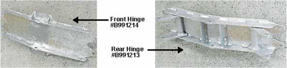
2 Installing the ABSORB 350 The following is the installation and maintenance instructions for an Absorb 350 System when it is attached to Portable or Permanent Concrete Barriers. Test level 2 and 3 configurations are the same with the exception of the number of Absorb 350 elements used o Test level 2 requires 5 Absorb 350 elements o Test level 3 requires 9 Absorb 350 elements This system is designed to attach to Portable or Permanent Concrete Barrier with section lengths of at least 3.1 metres. Terminology The following pictures show the elements and assemblies that comprise the Absorb 350 System. Ph or visit 3 October 07 / Page 2


3 Ph or visit 3 October 07 / Page 3
4 Figure 1: ABSORB 350 TL2 & TL3 with PCB Ph or visit 3 October 07 / Page 4

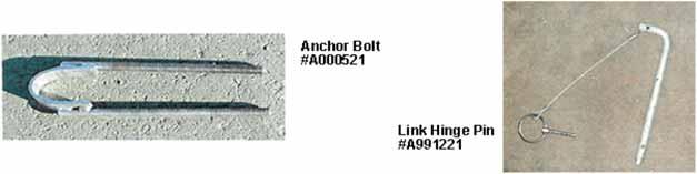
5 Installation Instructions Two people can easily accomplish the initial installation. The installation should be completed prior to filling the energy absorbing elements with water. It is not necessary but is easier to start setting the assembly from the concrete barrier wall end and assemble towards the nosepiece. STEP l Install the Adapter to the Portable Concrete Barrier wall. Use the following steps to install the Adaptor. Step 1.1 Place the two Anchor Bolts (AOOO521 ) into the Adapter (BOOO520) as shown. The bolts should be placed in the upper and lower holes if they will not interfere with the mounting on the end of the concrete barrier If there is interference use the closest holes to the top and bottom that is possible. Step 1.2 Place both anchor bolts through both plates as shown in the drawing. Start two nuts on each anchor bolt and push the anchor bolt to the rear until the nuts are against the plate. Ph or visit 3 October 07 / Page 5


6 Step 1.3 In the event that the taper adapter is installed on a permanent concrete wall, mounting bolts must be installed. The taper adapter should be set against the wall in its proper position. A punch can be used to mark the concrete in the four spots that the anchor bolts shown above would be located. Then four 12.5mm wedge anchor bolts need to be installed. Then install the taper adapter, torque the 12.5mm nuts on the wedge anchor bolts to Nm. Place the adapter at the end of the Portable Concrete Barrier wall. Insert the Portable Concrete Barrier pin through the two loops of the Portable Concrete Barrier and the two loops of the anchor bolts as shown. Tighten the four nuts on the Anchor Bolts to a torque of 15 ft/lbs. Then install a jam nut against the first nut with a torque of Nm. Step 1.4 Bolt the left and right Strap Adapter to the Taper Adapter. BOO0207 & BOO0209 Hold the top edge of the Strap Adaptor parallel with the road surface. Mark the rear holes (2) of the Strap Adaptor on the concrete barrier. Step 1.5 At each of the four (4) marks made above on the Portable Concrete Barrier drill a 12.5mm diameter hole 94mm deep. Ph or visit 3 October 07 / Page 6

 to the Hinge")

7 Step 1.6 Install four (4) 12.5 x 106mm (wedge anchor) cement anchor bolts. Place one 12.5mm flat washer and nut on each anchor bolt. Torque the nuts to Nm. Step 1.7 Install the Hinge Plate Adapter (BOOO611) onto the Taper Adapter as shown with eight (8) 12.5mm X 32mm NC GR 5 CADII PLTD bolts STEP 2 Install the first Energy Absorbing Element (Type "A") to the Hinge Plate Adapter. For element assembly see pages C-10 and C-11. Step 2.1 Install the centre pivot bolt, 12.5mm X 200mm and 12.5mm nylock nut. Tighten the nut only until the end of the bolt threads protrude out of the nylon portion of the nut. Ph or visit 3 October 07 / Page 7


8 Step 2.2 Install a Link Hinge Pin on each side of the hinge. Then make sure that the clip that is attached to the end of the chain is installed into the hole in the end of the Link Hinge Pin. STEP 3 Install the Energy Absorbing Elements. Install the Centre Pivot Bolt and the two Link-Hinge Locking Pins on each element. Test Level 2 - install five (5) elements total Test Level 3 - install nine (9) elements total. There are two types of Energy Absorbing Elements. Each type has a forward and rearward end. The forward end is considered the end that faces the Nose Piece. The rearward end faces the Concrete Barrier wall. The two types of elements are identified by the number of vertical indentations along each side in relation to the front and rear hinges. See elements on page C-1. When the Absorb 350 system is assembled, it is important to ensure that the two types of elements are ALWAYS ASSEMBLED IN AN ALTERNATING FASHION as shown in Figure 1. Thus, when you look down either side of the assembled system, you should see an alternating pattern of vertical indentations (i.e. two, one, two, one, etc.). NOTE: The second and third elements of Test Level 3 systems must have two vent/fill holes. If elements are not available with the two vent/fill holes in the top, the second hole must be cut in these two elements. The whole layout and size measurements are the same as the existing hole. See figure 1 drawing of Test Level 3. Ph or visit 3 October 07 / Page 8

9 STEP 4 Six tabs are loosely bolted (so they swivel for adjustment) onto the last hinge assembly before the Nose Piece. These tabs are the mounting points for the nosepiece. Three of the tabs have nuts welded onto one end. These go on the top of the bottom bar of the hinge assembly. The three tabs with a hole in each end go on the bottom side of the top bar of the assembly as shown below. (These tabs may already be installed.) STEP 5 Install the nosepiece on the end of the last Type A element. There are three 12.5mm X 150mm bolts that secure the nosepiece to the tabs on the hinge assembly. There are three access holes in the nosepiece that allows installation of these bolts. These bolts must be securely tightened. It is very important that the Nose Piece does not become detached during an impact. STEP 6 If necessary adjust the Energy Absorbing Elements so there is a straight alignment with the downstream QMB system. Ph or visit 3 October 07 / Page 9

10 STEP 7 Fill all of the Energy Absorbing Elements with water, except the first element. The plastic container that attaches to the nosepiece is the only container that does not have any water. The remaining containers are filled with water to a level that is within 50mm from the top of the container. Test Level 2: Fill 4 elements Test Level 3: Fill 8 elements NOTE: Filling the element attached to the nose piece with water will cause the system to perform improperly and may cause serious bodily injury. In regions where the water filled Absorb 350 elements could become frozen, proper antifreeze agents should be used. Care should be taken to ensure that proper antifreeze agents are used in accordance with local regulations, environmental concerns and ensuring that any post impact liquid on the road surface does not constitute an undue hazard to adjacent motorists. The Absorb 350 elements should be inspected regularly to ensure that the elements that are intended to contain water (or antifreeze fluid) are kept at adequate fill levels. STEP 8 Install the evaporation prevention cap into the top of each plastic container. The cap needs to be securely pushed down to prevent evaporation. In addition the tie strap should be securely fastened to the plastic element. STEP 9 Installing delineation: Depending on local authority specifications, install delineation as necessary to the front of the painted nosepiece. Inspection: The metal components and fasteners of the system should be periodically inspected to ensure that the system remains intact and able to perform in a safe and effective manner. Ph or visit 3 October 07 / Page 10
11 Replacement of damaged units: Any component within the system that becomes damaged should be replaced immediately. Assembly of Energy Absorbing Elements It is necessary to determine if a Type A Element or a Type B Element is to be assembled. A Type A can be converted to a Type B or vice versa simply by reversing the plastic within the hinge system. Follow the instructions outlined below. Figure 2: ABSORB 350 Element Assembly Ph or visit 3 October 07 / Page 11
12 STEP 1 Install the 12.5mm galvanised jam nuts onto one end of the four threaded rods. The nut on each end should be threaded on the rod about 37mm. STEP 2 Install the four threaded rods through the hinge ends and in the horizontal grooves of the energy absorbing element as shown above and loosely start the 12.5mm nuts. It is sometimes easier to secure all four rods to one hinge end, then slide this assembly onto the element, then attach the opposite hinge end. STEP 3 Evenly tighten the outer 12.5 mm until the hinge assembly on each end is making firm contact with the energy absorbing element. After this adjustment is made, tighten each of the four outer nuts one full turn. STEP 4 Thread the jam nuts against the backside of the hinges. Torque the jam nuts to 54.23Nm NOTE: Please ensure you have read and understood the Limitations and Warnings Information provided in the front of this product manual before beginning any installation procedures. Ph or visit 3 October 07 / Page 12
Introduction 3. System Overview 3. Before Installation 3. Limitations and Warnings 4. Safety Statements 4. Parts Identification 5.
 June 2015 Table of Contents Introduction 3 System Overview 3 Before Installation 3 Limitations and Warnings 4 Safety Statements 4 Parts Identification 5 Preparation 7 Soil Conditions 7 Tools Required 7
X-350 Guardrail End Terminal
 X-350 Guardrail End Terminal Tangent and Flared Step by Step Instructions for the Tangent and Flared Applications Ph 0800 655 200 or visit www.csppacific.co.nz August 2011 / Page 1 Table of Contents Introduction
X-Tension TM Guardrail End Terminal
 Installation and Maintenance Manual X-Tension TM Guardrail End Terminal Step by Step Instructions for the Tangent, Flared and Median Applications Barrier Systems Sales and Service 3333 Vaca Valley Pkwy,
X-TENSION 350 Guardrail End Terminal Tangent and Flared
 X-TENSION 350 Guardrail End Terminal Tangent and Flared December 2015 Table of Contents Introduction 3 System Overview 3 Before Installation 3 Limitations and Warnings 4 Safety Statements 4 Parts Identification
Hardware and Components:
 Hardware and Components: (A) 5/16 x 2 Hex Bolt (B) 5/16 x 2-1/4 Hex Bolt (C) 5/16 x 2-1/2 Hex Bolt (D) 4X 5/16 x 3/4 Hex Bolt (E) 4X 5/16 x 1-1/4 Hex Bolt (F) 11X 5/16 Flat Washer (G) 12X 5/16 Nylock Nut
RBP-1215B-RX DODGE RAM QUAD CAB RX3
 RBP-1215B-RX3 2002-2017 DODGE RAM 15-3500 QUAD CAB RX3 Passenger side RX-3 Side Step Drill Template Passenger side rear Modular Bracket (6) L Support Brackets Driver side rear Modular Bracket Driver side
SKT-SP Tangent Terminal
 Assembly Instructions for metric SKT-SP Tangent Terminal & FLEAT-SP Flared Terminal SP Standard Post System Guardrail Terminals ROAD SYSTEMS, INC. P. O. Box 2163 Big Spring, Texas 79721 Phone: (432) 263-2435
Highway Care Ltd. Xtension 110 P4 Terminal & Xtension 110 Double Sided P4 Terminal DESIGN, INSTALLATION & MAINTENANCE MANUAL REVISION 1E
 Xtension 110 P4 Terminal & Xtension 110 Double Sided P4 Terminal DESIGN, INSTALLATION & MAINTENANCE MANUAL REVISION 1E Highway Care Limited Page 1 Revision 1E Contents Page Introduction 3 Before Installation
Terminus TM CEN End Terminal
 Product/Installation Manual Corporate Offices: 35 East Wacker Dr., 11 th Floor Chicago, IL 60601-2076, USA Tel: +1 (312) 467-6750 Fax: +1 (312) 467-1356 http://www.energyabsorption.com/ Quixote Europe
Hardware and Components:
 Hardware and Components: (A) 4X 5/16 x 1 Carriage Bolt (B) 2X 5/16 x 2-1/4 Carriage Bolt (C) 2X 5/16 x 3-1/4 Hex Bolt (D) 2X 5/16 x 3/4 Hex Bolt (E) 2X 5/16 x 1-1/4 Hex Bolt (F) 5/16 x 2-1/4 Hex Bolt (G)
U.S. Rack, Inc Falcon Drive, Madera, CA APR17 INSTALLATION AND USE INSTRUCTIONS for SIDE-MOUNT LADDER RACK
 U.S. Rack, Inc. 2850 Falcon Drive, Madera, CA 93637 15APR17 INSTALLATION AND USE INSTRUCTIONS for SIDE-MOUNT LADDER RACK WARNING: Do NOT attempt to install or use this rack without following all instructions.
Thank you for purchasing our product! *Please read these instructions and follow them step by step.*
 07/07/08.rev1 PAGE 1 OF 11 601AL VERTICAL 60120VL LIFT W/CHAIN DRIVE WINCH Thank you for purchasing our product! *Please read these instructions and follow them step by step.* Step 1. Separate and group
Size Grade Torque 9/ ft/lbs. 5/ ft/lbs. 3/ ft/lbs. 7/ ft/lbs ft/lbs.
 8-3 HJ3205,Rev 4 BOlT TORQUE SPECIfICATIONS STANDARD BOlTS: Size Grade Torque 5/6 5 20 ft/lbs. 3/8 5 35 ft/lbs. 7/6 5 56 ft/lbs. /2 5 85 ft/lbs. Size Grade Torque 9/6 5 23 ft/lbs. 5/8 5 70 ft/lbs. 3/4
INSTALLATION INSTRUCTIONS 3 BULL BAR 99-04, 04 "HERITAGE" F-150/250LD 2WD, 97-04, 04 "HERITAGE" 4WD WD EXPEDITION/ WD EXPEDITION PART
 INSTALLATION INSTRUCTIONS 3 BULL BAR PART #B-F1971;B-F2971 PARTS LIST: 1 Bull Bar 2 12-1.75mm x 130mm x 40mm Hex Bolts 1 Driver/Left Mounting Bracket 4 12-1.75mm x 35mm Hex Bolts 1 Passenger/Right Mounting
Ford Pick Up Rear leaf Spring Kit Installation Instructions
 1948-1956 Ford Pick Up Rear leaf Spring Kit Installation Instructions 1-800-984-6259 www.totalcostinvolved.com Parts 48 inch leaf (2) springs (4) U-bolts 3/8-24 x l 1/4bolts (16) & nuts (2) 1/2-20 x 4
Installation Instructions
 DODGE 16K Industry Standard Rail Custom Mounting Kit #2728 Gross Trailer Weight (Maximum)...16,000 lbs. Vertical Load Weight (Max. Pin Weight)...4,000 lbs. SYSTEM TOW CAPACITY Please note, in order to
ALL SEASON PATIO COVER
 ALL SEASON PATIO COVER 61 Where the All Season Patio Cover is to be attached to the home, create a level line showing where the top of the mounting rail is to be located. Install each section with the
Assembly Instructions for. for 31" MGS (Midwest Guardrail System) ROAD SYSTEMS, INC.
 ROAD SYSTEMS, INC.") MSKT Assembly Instructions for MASH Tangent Terminal for 31" MGS (Midwest Guardrail System) ROAD SYSTEMS, INC. P. O. Box 2163 Big Spring, Texas 79721 Phone: (432) 263-2435 FAX: (432) 267-4039 Technical
MSKT Assembly Instructions for MASH Tangent Terminal for 31" MGS (Midwest Guardrail System) ROAD SYSTEMS, INC. P. O. Box 2163 Big Spring, Texas 79721 Phone: (432) 263-2435 FAX: (432) 267-4039 Technical
`48-`56 Ford Pickup Rear leaf Spring Kit Installation Instructions Tech Line:
 `48-`56 Ford Pickup Rear leaf Spring Kit Installation Instructions Tech Line: 1-855-693-1259 www.totalcostinvolved.com CHECK ALL PARTS INCLUDED IN THIS KIT TO THE PARTS LIST BEFORE INSTALLING THE KIT.
US RACK, Inc Falcon Drive, Madera, CA
 US RACK, Inc. - 2850 Falcon Drive, Madera, CA 93637-559-661-3050 INSTRUCTIONS for MOTORCYCLE RACK with Cradling Wheel Chocks WARNING: Do NOT attempt to install or use this rack without following all instructions.
TYGER ARMORTM. Parts List BEFORE INSTALLATION WARNING. Customer Support TG-AM2C /8. x1 Driver/Left Side Armor
 TYGER ARMORTM TG-AM2C20028 Customer Support Parts List x1 Driver/Left Side Armor BEFORE INSTALLATION READ INSTRUCTIONS CAREFULLY BEFORE STARTING INSTALLATION. REMOVE CONTENTS FROM BOX AND VERIFY ALL PARTS
Camaro License Plate Frame Bracket, V8
 PART #59389 2010-11 Camaro License Plate Frame Bracket, V8 PACKING LIST Before installation, use this checklist to make sure all necessary parts have been included. ITEM QTY CHECK PART NUMBER DESCRIPTION
frame bracket Dodge x 2 & 4 x 4 (6-1/2 & 8 Boxes Includes Mega Cab)
") , Rev 4 02/19 frame bracket 8552026 Dodge 3500 4 x 2 & 4 x 4 (6-1/2 & 8 Boxes Includes Mega Cab) 14 5 7 2 4 11 9 10 17 3 6 1 8 13 15 16 18 12 ITEM PART # DESCRIPTION QTY. 1 00085.50 FLAT WASHER 10 2 00248
, Rev 4 02/19 frame bracket 8552026 Dodge 3500 4 x 2 & 4 x 4 (6-1/2 & 8 Boxes Includes Mega Cab) 14 5 7 2 4 11 9 10 17 3 6 1 8 13 15 16 18 12 ITEM PART # DESCRIPTION QTY. 1 00085.50 FLAT WASHER 10 2 00248
Introduction. Rocky Mountain Westy Swing Away Carrier Kit Installation Instructions
 Rocky Mountain Westy Swing Away Carrier Kit Installation Instructions Introduction Thank you for purchasing the Rocky Mountain Westy Swing Away Carrier Kit. We pride ourselves in the products we develop
Oxford Stalls Installation Instructions
 Oxford Stalls Installation Instructions RAMM Horse Fencing and Stalls 13150 Airport Hwy. Swanton, OH 43558-9615 1-800-434-8456 Rev. 8/15/17 Before You Start Typical stall sizes are 10 x 10, 12 x 12 or
Pickup Box Utility Rack Package Installation (Instruction ID: )
") 017 Chevrolet Colorado Pickup - WD (VIN S) Canyon, Colorado Accessory Installation Manual N America Document ID: 3966961 Pickup Box Utility Rack Package Installation (Instruction ID:3144879) Installation
017 Chevrolet Colorado Pickup - WD (VIN S) Canyon, Colorado Accessory Installation Manual N America Document ID: 3966961 Pickup Box Utility Rack Package Installation (Instruction ID:3144879) Installation
Installation Instructions
 CHEVY / GMC 20K Industry Standard Rail Custom Mounting Kit #2724 Gross Trailer Weight (Maximum)...20,000 lbs. Vertical Load Weight (Max. Pin Weight)...5,000 lbs. SYSTEM TOW CAPACITY Please note, in order
FRAME BRACKET. Doing Our Best to Provide You the Best. Ford. Page 1. BOlT TORQUE SPECIFICATIONS HJ31000,Rev 0
 2-13 HJ31000,Rev 0 Ford BOlT TORQUE SPECIFICATIONS METRIC BOlTS Size Grade Torque 8mm 8.8 23 ft/lbs. 10mm 8.8 45 ft/lbs. 12mm 8.8 78 ft/lbs. 14mm 8.8 125 ft/lbs. STANDARD BOlTS Size Grade Torque 5/16 5
INSTALL INSTRUCTIONS WELCOME TO THE NEWAGE PERFORMANCE CABINETRY SERIES NEWAGE STEEL WELDED CABINETRY
 NEWAGE STEEL WELDED CABINETRY WELCOME TO THE NEWAGE PERFORMANCE CABINETRY SERIES ALL CABINETS MUST BE MOUNTED TO STUDS ON A SECURE WALL, AS PER THESE INSTRUCTIONS. FAILURE TO DO SO MAY RESULT IN SERIOUS
FRAME BRACKET. Doing Our Best to Provide You the Best. Ford F250, F350 & F parts list. Page 1. 2/17 HJ32002,Rev 2.
 2/17 HJ32002,Rev 2 BOlt torque specifications MEtRiC BOlts size Grade torque 8mm 8.8 23 ft/lbs. 10mm 8.8 45 ft/lbs. 12mm 8.8 78 ft/lbs. 14mm 8.8 125 ft/lbs. standard BOlts size Grade torque 5/16 5 18 ft/lbs.
ASSEMBLY AND CARE INSTRUCTIONS JUST FOR KIDS 355
 ASSEMBLY AND CARE INSTRUCTIONS VERSION: 8920100 (Revised 06/16) JUST FOR KIDS 355 SALES AND SERVICE spiethamerica.com Canada and International 135 Forestview Road, PO Box 40 Orillia, Ontario, Canada L3V
Important Loading Information. Tools Required. Meridian Lateral Files Instructions
 Y Meridian Lateral Files Instructions! WARNING Failure to observe stated capacities below will result in unsafe usage conditions, causing possible product damage or personal injury. Important Loading Information
ASSEMBLY INSTRUCTIONS FOR MAR-K BEDSIDES AND GM FLUSH TAILGATE WITH HANDLE
 ASSEMBLY INSTRUCTIONS FOR MAR-K BEDSIDES AND 41-53 GM FLUSH TAILGATE WITH HANDLE Build the box assembly according to the MAR-K assembly instructions. When installing the tailgate and latching mechanisms
INSTALLATION INSTRUCTIONS 3"/4 BENT END SIDEBARS FORD F-150 SUPERCREW PART # DZ /DZ
 INSTALLATION INSTRUCTIONS 09-12 FORD F-150 SUPERCREW PART # DZ 372697/DZ 372699 PARTS LIST: 1 Driver/Left Sidebar 4 1/2 Lock Washers 1 Sidebar 4 12mm x 32mm OD x 3mm Flat Washers 1 Driver/Left Mounting
Installation Instructions
 TOYOTA 16K Industry Standard Rail Custom Mounting Kit #2748 Gross Trailer Weight (Maximum)...16,000 lbs. Vertical Load Weight (Max. Pin Weight)...4,000 lbs. SYSTEM TOW CAPACITY Please note, in order to
FLOE DOCK FURNITURE WARNING ASSEMBLY INSTRUCTIONS
 FLOE DOCK FURNITURE ASSEMBLY INSTRUCTIONS KIT P/N 510-00400-02 KIT P/N 510-00405-02 KIT P/N 510-00406-02 KIT P/N 510-00410-02 WARNING IT IS THE INSTALLER S RESPONSIBILITY TO PROPERLY INSTALL this chair
Installation Instructions
 FORD 20K Industry Standard Rail Custom Mounting Kit #2738 Gross Trailer Weight (Maximum)...20,000 lbs. Vertical Load Weight (Max. Pin Weight)...5,000 lbs. SYSTEM TOW CAPACITY Please note, in order to determine
400A 40113V, 401A 40120V, & 401AL 40120VL ALUMINUM VERTICAL 4000 LB LIFT INCLUDES SCREW LEG ASSEMBLY INSTRUCTIONS
 12/11/07 PAGE 1 OF 12 400A 40113V, 401A 40120V, & 401AL 40120VL ALUMINUM VERTICAL 4000 LB LIFT INCLUDES SCREW LEG ASSEMBLY INSTRUCTIONS Thank you for purchasing our product! *Please read these instructions
Installation Instructions
 DODGE RAM 2500 20K Industry Standard SuperRail Custom Mounting Kit #2336 Gross Trailer Weight (Maximum)...20,000 lbs. Vertical Load Weight (Max. Pin Weight)...5,000 lbs. SYSTEM TOW CAPACITY Please note,
Installation Manual for Gate Guard
 Installation Manual for Gate Guard Fast Opening Barrier Gate for Emergencies and Contra Flow Innovative safety technology from SGGT of Germany TABLE OF CONTENTS Page Number Preface 3 Introduction 3 System
ShorePort PWC Lift Instructions " x 138" Sandstone ShorePort " x 138" White ShorePort " x 138" Tan ShorePort
 ShorePort PWC Lift Instructions 00-8" x 8" Sandstone ShorePort 009-8" x 8" White ShorePort 090-8" x 8" Tan ShorePort....... - PUT SAFETY FIRST To avoid the risk of personal injury or death, study and fully
CHEVY/GMC SuperRail Mounting Kit #3117
 CHEVY/GMC SuperRail Mounting Kit #3117 #3100 SuperGlide (12K) Gross Trailer Weight (Maximum) Vertical Load Weight (Max. Pin Weight) 12,000 lbs. 3,000 lbs. Installation Instructions SPECIFICATIONS Fits
Installation Instructions
 FORD 20K Industry Standard Rail Custom Mounting Kit #2760 Gross Trailer Weight (Maximum)...20,000 lbs. Vertical Load Weight (Max. Pin Weight)...5,000 lbs. SYSTEM TOW CAPACITY Please note, in order to determine
Ford Raptor Venom Front Bumper Installation Instructions
 PREPARATION 2010 2014 Ford Raptor Venom Front Bumper Installation Instructions 1. Disconnect the negative terminal on the battery. Park the vehicle on level ground and set the emergency brake. 2. We recommend
Chapter 6 Frame And Lens Repairs
 Chapter 6 Frame And Lens Repairs 6.1 General Information All maintenance on the frame of the EXO Full-Face mask can be accomplished with common hand tools. 6.2 Lens Replacement Tools required: Dow DC-111
BOLT TORQUE SPECIFICATIONS
 ASSEMBLY OPERATION REPLACEMENT PARTS 04-01 TP20063,Rev.2 1998 Chevy S-10 (2wd) (page 1) 1998 Isuzu Hombre (2wd) (page 4) BOLT TORQUE SPECIFICATIONS STANDARD BOLTS: METRIC BOLTS: Size Grade Torque Size
INSTALLATION INSTRUCTIONS FOR PLASCORE NARROW STILE DOORS
 INSTALLATION INSTRUCTIONS FOR PLASCORE NARROW STILE DOORS The following information is provided by Plascore, Inc., as a general guideline for the installation of the Plascore Narrow Stile Door and Jamb
WPS crew Doors Installation instructions
 WPS-132-133 crew Doors Installation instructions ORDER OF INSTALLATION FOR A COMPLETE ENCLOSURE OF A CREW WPS (Weather Protection System) IS AS FOLLOWS: 1. Heater 2. Rear Thresholds - Right Hand & Left
Dublin Stalls Installation Instructions
 Dublin Stalls Installation Instructions RAMM Horse Fencing and Stalls 13150 Airport Hwy. Swanton, OH 43558-9615 1-800-434-8456 Rev. 9/13/17 Part Identification Round Track Bracket (4) (Not Painted) Round
TITAN INDUSTRIAL RACK 4-FOOT TALL / 3-SHELF
 TITAN INDUSTRIAL RACK 4-FOOT TALL / 3-SHELF DXST4500 IMPORTANT: Please read this manual carefully before assembling this storage rack and save it for reference INSTRUCTION MANUAL 3 TABLE OF CONTENTS TECHNICAL
Installation Instructions
 CHEVY / GMC 24K Industry Standard Rail Heavy Duty Custom Mounting Kit #2226 Gross Trailer Weight (Maximum)...24,000 lbs. Vertical Load Weight (Max. Pin Weight)...6,000 lbs. SYSTEM TOW CAPACITY Please note,
Pressure Vessel Assembly Instructions
 Pressure Vessel Assembly Instructions 1) Measure aluminum tube outer diameter 2) Machine both end caps and only drill pilot holes for all hoes shown 3) Weld both end caps onto the aluminum tube and be
Contractors Rack Assembly and Installation Instructions
 Part # 18601 & 16601 Contractors Rack Assembly and Installation Instructions 4751 Littlejohn St. Unit A, Baldwin Park, CA 91706 Page 1 of 12 11/13/08 Thank you for purchasing the Paramount Restyling Contractors
Installation Instructions
 CHEVY / GMC 20K Industry Standard Rail Custom Mounting Kit #2724 Gross Trailer Weight (Maximum)...20,000 lbs. Vertical Load Weight (Max. Pin Weight)...5,000 lbs. SYSTEM TOW CAPACITY Please note, in order
FRAME BRACKET. Doing Our Best to Provide You the Best. Ford F /2, 6 1/2 & 8 Boxes. BOlT TORQUE SPECIFICATIONS. 7/17 HJ31001,Rev 3
 Ford F150 5 1/2, 6 1/2 & 8 Boxes 7/17 HJ31001,Rev 3 BOlT TORQUE SPECIFICATIONS METRIC BOlTS Size Grade Torque 8mm 8.8 23 ft/lbs. 10mm 8.8 45 ft/lbs. 12mm 8.8 78 ft/lbs. 14mm 8.8 125 ft/lbs. STANDARD BOlTS
Sales & Service. JFK - Just For Kids. sasportonline.com. 135 Forestview Road 7879 Will Rogers Blvd.
 Sales & Service sasportonline.com SA Sport (Canada) SA Sport (U.S.A.) 135 Forestview Road 7879 Will Rogers Blvd. P.O. Box 40 Fort Worth, Texas Orillia, Ontario USA 76140 Canada L3V 6H9 Telephone: (705)
Modular XP Ramp Assembly Manual
 Modular XP Manual 1 Contents Overview... 2-5 Section 1: 1.1 Tools required...6 1.2 Hardware list...6 Ramp & Platform Standard Parts 2.1 Ramp Parts...7 2.2 Platform Parts...8 2.3 Standard Platform Configurations...
Installation for Full Size Polaris Ranger Crew Doors
 Installation for Full Size Polaris Ranger Crew Doors Order of Installation: Heater Doors Wiper on to Windshield Windshield Top & Back Panel Note: Most of the steps in these instructions need to be repeated
00108/00110 INSTRUCTION MANUAL
 00108/00110 INSTRUCTION MANUAL Removable and Adjustable Mudflap System IMPORTANT! Exhaust Systems Note: Any modifications to the factory installed exhaust system may void your manufacturer s warranty.
TRUE TECHNICAL SERVICE MANUAL - ALL MODELS. DOORS/DRAWERS/LIDS
 DOORS/DRAWERS/LIDS 55 56 NOTES DOORS/DRAWERS/LIDS Swing s 73 74 NOTES INSTALLATION OF A GDM-SWING DOOR Phillips Head Screwdriver (2) - 1/8" Drift Punches (forged) Top Bracket NOTE: It may be necessary
RH-412 STEEL DOORS INSTALLATION INSTRUCTIONS
 RH-412 STEEL DOORS INSTALLATION INSTRUCTIONS By following the steps outlined below, the assembly, installation and adjustment of the steel doors, will be a simple process. Let s start with the Driver Side.
INSTALLATION INSTRUCTIONS, AND PARTS LIST
 INSTALLATION INSTRUCTIONS, AND PARTS LIST LB20 SERIES RAMPS Link Mfg. Ltd. 223 15th St. N.E. Sioux Center, IA USA 51250-2120 (712) 722-4868 Fax (712) 722-4779 QUESTIONS? CALL CUSTOMER SERVICE 1-800-248-3057
Modular XP Ramp Assembly Manual
 Modular XP Manual 1 Contents Overview... 2-5 1.1 Tools required...6 1.2 Hardware list...6 Ramp & Platform Standard Parts 2.1 Ramp Parts...7 2.2 Platform Parts...8 2.3 Standard Platform Configurations...
TITAN INDUSTRIAL RACK 6-FOOT TALL / 4-SHELF
 TITAN INDUSTRIAL RACK 6-FOOT TALL / 4-SHELF DXST10000 IMPORTANT: Please read this manual carefully before assembling this storage rack and save it for reference INSTRUCTION MANUAL 3 TABLE OF CONTENTS
QuadGuard. Assembly Manual Stemmons Freeway Dallas, Texas 75207
 QuadGuard Assembly Manual 2525 Stemmons Freeway Dallas, Texas 75207 Important: These instructions are to be used only in conjunction with the assembly, maintenance, and repair of the QuadGuard system.
INSTALLATION INSTRUCTIONS RH 412 STEEL DOORS
 By following the steps outlined below, the assembly, installation and adjustment of the steel doors, will be a simple process. Let s start with the Driver Side. Note: Having the hood open makes the job
FLOOR ANCHOR SYSTEM APPLICATIONS L TRACK APPLICATIONS
 FLOOR ANCHOR SYSTEM APPLICATIONS Sure-Lok recommends the following for floor anchor system layout and installation. These recommendations are not all-inclusive and may not be applicable to every system
US RACK, Inc Falcon Drive, Madera, CA
 US RACK, Inc - 2850 Falcon Drive, Madera, CA 93637-559-661-3050 INSTALLATION AND USE INSTRUCTIONS for Long-John Extension Ladder Rack WARNING: Do NOT attempt to install or use this rack without following
FORD #2228. Gross Trailer Weight (Maximum)...24,000 lbs. Vertical Load Weight (Max. Pin Weight)...6,000 lbs. SYSTEM TOW CAPACITY
...24,000 lbs. Vertical Load Weight (Max. Pin Weight)...6,000 lbs. SYSTEM TOW CAPACITY") FORD 24K Industry Standard Rail Heavy Duty Custom Mounting Kit #2228 Gross Trailer Weight (Maximum)...24,000 lbs. Vertical Load Weight (Max. Pin Weight)...6,000 lbs. SYSTEM TOW CAPACITY Please note, in
FORD 24K Industry Standard Rail Heavy Duty Custom Mounting Kit #2228 Gross Trailer Weight (Maximum)...24,000 lbs. Vertical Load Weight (Max. Pin Weight)...6,000 lbs. SYSTEM TOW CAPACITY Please note, in
Installation And Care Instructions. Vertical Honeycomb Shades
 Installation And Care Instructions Vertical Honeycomb Shades Rev 5/2013 Table Of Contents Getting Started... 3 Parts Overview... 4 Materials Required... 5 Tools Required... 6 Outside Mount Installation...
INSTALLATION INSTRUCTIONS
 NOTE: Bolts should remain hand tight until all bolts are installed. STEP 1 Installing the door base (both sides). 1. Locate the outer, roll cage, mounting bolt (passenger side is shown in the illustration).
INSTALLATION AND MAINTENANCE MANUAL X-TENSION. NCHRP 350 TL-3 Tangent / Flared End Terminal and Median Attenuator
 INSTALLATION AND MAINTENANCE MANUAL X-TENSION NCHRP 350 TL-3 Tangent / Flared End Terminal and Median Attenuator INSTALLATION AND MAINTENANCE MANUAL Table of Contents Introduction 3 System Overview 3 Before
INSTALLATION AND CARE INSTRUCTIONS
 INSTALLATION AND CARE INSTRUCTIONS Vertical Applications Honeycomb Shades CONTENTS Introduction...2 Before You Begin...3 Vertical Application Parts Overview...4 Materials Required...5 Tools Required...6
U.S. RACK, Inc Falcon Drive, Madera, CA
 U.S. RACK, Inc. - 2850 Falcon Drive, Madera, CA 93637-559-661-3050 INSTRUCTIONS for FIFTH WHEEL RACK Models 2010-4ADC and 2010-4ADCD WARNING: Do NOT attempt to install or use this rack without following
Installation Manual. QuadGuard System. The World Wide Standard In Crash Cushions ENERGY ABSORPTION
 The World Wide Standard In Crash Cushions ENERGY ABSORPTION SYSTEMS, INC. A Quixote Company Saving Lives By Design Corporate Offices: 35 East Wacker Dr., 11th Floor Chicago, IL 60601-2076 Telephone: (312)
ALUMINUM FOOTBALL GOALS INSTRUCTIONS WARNING WARNING Upright. Upright. Flag. Flag. Offset Pole.
 ALUMINUM FOOTBALL GOALS INSTRUCTIONS 800-67-090 Flag Flag Ground Sleeve Anchor Kit WARNING Football goals are shipped unassembled. Read all instructions thoroughly before attempting to assemble this equipment.
Agave Standard Series
 Mailing Address: 033 San Elijo Ave, #464 Cardiff, CA 9007 619.708.917 619.330.88 fax info@agaveiron.com www.agaveiron.com Agave Standard Series Flat Track Hardware Systems General Information and Installation
PFW 6851 Display Wall Mount, Turn & Tilt 80 kg INSTALLATION INSTRUCTIONS
 Display Wall Mount, Turn & Tilt 80 kg INSTALLATION INSTRUCTIONS 9531-007-Z00-01 Table of Contents Warning Statements 2 Parts List 3 Installation Tools 3 Wood Stud Installation 5 Concrete Surface Installation
Installation Instructions. Installation Type
 Installation Instructions 800 & 8050 Slide Track Door Closers Non Hold Open & Hold Open Models Note: Hold open models are not permitted to be installed in Listed fire door assemblies. PULL SIDE MOUNTED
PRORAC CONTRACTOR SERIES UNIVERSIAL STEEL TRUCK / CAP RACK INSTALLATION INSTRUCTIONS
 PRORAC CONTRACTOR SERIES UNIVERSIAL STEEL TRUCK / CAP RACK INSTALLATION INSTRUCTIONS 1000 Lb. Capacity Bed Mount 750 Lb. Capacity Cap Mount Package Contents: Parts Hardware (4) Legs (12) 3/8-16 x 1-1/4
Floating Lake Truss Dock Instructions
 Table of Contents Floating Lake Truss Dock Instructions 1. Dock Assembly and Set-Up 1.1 Installing Dock Floats 1.2 Positioning Quick Clips 1.3 Installing Anchor Posts 1.4 Installing Docks into the Water
OWNERS MANUAL. Model No " SLEEVE HITCH ROCK RAKE. CAUTION: Read Rules for Safe Operation and Instructions Carefully
 OWNERS MANUAL Model No. 45-0366 48" SLEEVE HITCH ROCK RAKE CAUTION: Read Rules for Safe Operation and Instructions Carefully Assembly Operation Maintenance Repair Parts the fastest way to purchase parts
southpaw enterprises, inc.
 Store these instructions in a safe place or with the enclosed maintenance checklist In-FUN-ity Climbing System Assembly Examples This example sheet is intended to supplement the instruction sheets that
Swivel Hoist Ring Page 142
 Swivel Hoist Ring Page 142 Hoist Rings Color coded to distinguish between UNC (Red) and Metric (Silver) thread types HR-125 M HR-125 Available in UNC and Metric thread sizes. UNC threads available in sizes
INSTALLATION INSTRUCTIONS
 INSTALLATION INSTRUCTIONS R5 STEP BOARD APPLICATION: 2009-2017 Dodge Ram 1500 Quad / Crew Cab 2010-2017 Dodge Ram 2500/3500 Crew Cab PART NUMBER: 28-51040, 28-51045, 28-51050, 28-51055 ITEM QUANTITY DESCRIPTION
Installation Instructions. Installation Type
 Installation Instructions 300 & 3050 Slide Track Door Closers Non Hold Open & Hold Open Models Note: Hold open models are not permitted to be installed in Listed fire door assemblies. PULL SIDE MOUNTED
Please read BOTH these Installation Instructions and the General Instructions prior to installing or operating this equipment.
 Attachment Tab Height: 13 Attachment Tab Width: 24 Please read BOTH these and the General Instructions prior to installing or operating this equipment. Serial Number 1. Blue Ox towing products and accessories
CHEVY/GMC SuperRail Mounting Kit #4423
 CHEVY/GMC SuperRail Mounting Kit #4423 #4100 SuperGlide (16K) #4400 SuperGlide (20K) Gross Trailer Weight (Maximum) Vertical Load Weight (Max. Pin Weight) 16,000 lbs. 4,000 lbs. Gross Trailer Weight (Maximum)
southpaw enterprises, inc.
 southpaw enterprises, inc. Store these instructions with the enclosed maintenance checklist in a safe place. You may also access them on our website. Instruction Sheet Wood Joist 2-1/2 Ft. Drop Ceiling
Installation Instructions
 CHEVY / GMC 16K Industry Standard Rail Custom Mounting Kit #2730 Gross Trailer Weight (Maximum)...16,000 lbs. Vertical Load Weight (Max. Pin Weight)...4,000 lbs. SYSTEM TOW CAPACITY Please note, in order
MantelMount. TM1A Installation Instructions IMPORTANT SAFETY INSTRUCTIONS - SAVE THESE INSTRUCTIONS
 MantelMount TMA Installation Instructions IMPORTANT SAFETY INSTRUCTIONS - SAVE THESE INSTRUCTIONS TM Thank you for choosing the MantelMount television wall mount. Please read this entire manual before
INSTALLATION INSTRUCTIONS ATV PLOW Mount Kit: PN Application: Sportsman 400, Magnum 425
 INSTALLATION INSTRUCTIONS ATV PLOW Mount Kit: PN 37845 Application: 1996-97 Sportsman 400, 1997-98 Magnum 425 Your safety, and the safety of others, is very important. To help you make informed decisions
E4-WM5-Y525A00 MOUNTING INSTRUCTION
 RAM 2500/3500 4WD B8 5100 (Dual Steering Damper Kit) The installation of these steering dampers must be performed only by experienced and qualified personnel. Read and follow the installation instructions
INSTALLATION AND CARE INSTRUCTIONS
 INSTALLATION AND CARE INSTRUCTIONS Vertical Applications Honeycomb Shades 52 C8-10-3401 Rev 2/14 CONTENTS Introduction...2 Before You Begin...3 Vertical Application Parts Overview...4 Materials Required...5
INSTALLATION MANUAL WEEKENDER STEEL LADDER RACK
 TRUCK STORAGE SOLUTIONS SECURING YOUR REPUTATION INSTALLATION MANUAL WEEKENDER STEEL LADDER RACK STEEL & ALUMINUM SIDE BOX WITH PACK RAT DRAWER UNITS MODELS ATTENTION: PLEASE READ AND UNDERSTAND ALL INSTRUCTIONS
Hiniker Company th St. P.O. Box 3407 Mankato, MN VEHICLE INSTALLATION INSTRUCTIONS FOR: CHEV/GMC 4x4: K1500 SILVERADO/SIERRA
 VEHICLE INSTALLATION INSTRUCTIONS FOR: CHEV/GMC x: 007 03 K500 SILVERADO/SIERRA Page of 5 Hiniker Company 58766 0th St. P.O. Box 307 Mankato, MN 5600 INSTRUCTION SHEET NO: 505 Rev. A August 0, 03 IMPORTANT:
HQ Pole Upgrade Kit for HQ Adjustable Table and HQ QuilTable Assembly Instructions 1
 HQ Pole Upgrade Kit for HQ Adjustable Table and HQ QuilTable Assembly Instructions QF09775 The pole upgrade kit can be used with or without the QF09700 HQ Precison-Glide track upgrade kit. What s Included
BUMP GATE FITTING INSTRUCTIONS.
 1 BUMP GATE FITTING INSTRUCTIONS. HEAVY DUTY MODEL FOR STEEL POSTS. Hinge post Lock post Bump arms Two-way lock Thank you for purchasing a Bump Gate. This device will provide you with many years of good
INSTALLATION INSTRUCTIONS
 INSTALLATION INSTRUCTIONS Trans4mer Grille Guard/Winch Mount For Chevrolet Silverado 1500HD & 2500 Kit 68162 This WARN Trans4mer system can be customized to give your Chevy Silverado a wide variety of
METAL BENDER OPERATING & MAINTENANCE INSTRUCTIONS Model Nos: CCB1 & CCB2 Part Nos: & CCB2 CCB1
 METAL BENDER Model Nos: CCB1 & CCB2 Part Nos: 7630073 & 7630074 CCB2 CCB1 OPERATING & MAINTENANCE INSTRUCTIONS 1206 1 The Compact Bender allows you to economically make a variety of bends in flat, square,