X-Tension TM Guardrail End Terminal
|
|
|
- Sabrina Rodgers
- 6 years ago
- Views:
Transcription


 374-6801 XT06 www.barriersystemsinc.")
1 Installation and Maintenance Manual X-Tension TM Guardrail End Terminal Step by Step Instructions for the Tangent, Flared and Median Applications Barrier Systems Sales and Service 3333 Vaca Valley Pkwy, Vacaville, CA Phone (707) Fax (707) XT
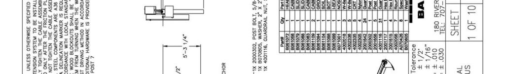
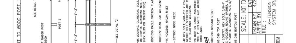
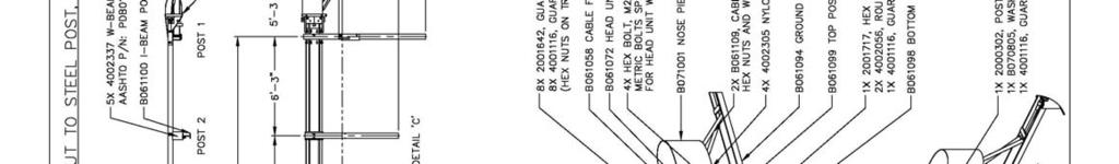
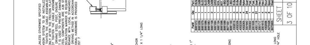
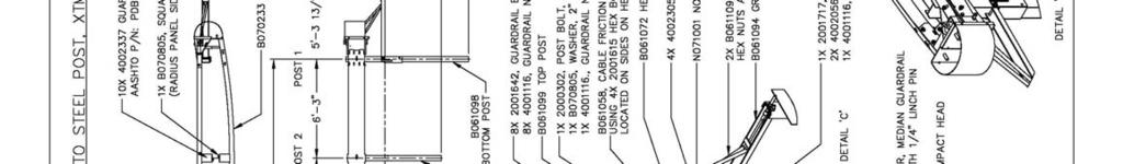
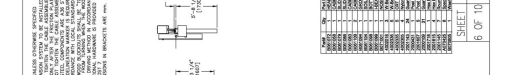
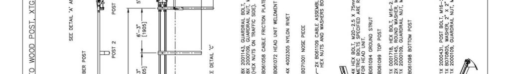
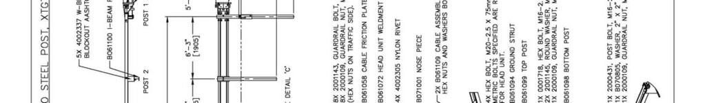
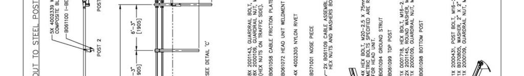
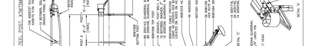
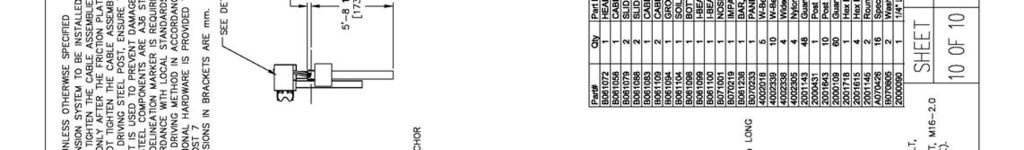
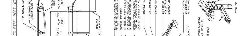
2 Table of Contents Introduction 3 System Overview. 3 Before Installation 3 Limitations and Warnings 4 Safety Statements 4 Parts Identification 5 Preparation 7 Soil Conditions.. 7 Tools Required.. 7 Before Starting.. 7 X-Tension Tangent Installation.. 8 X-Tension Flared Installation.. 16 X-Tension Median Installation. 18 Installation Checklist.. 24 MAINTENANCE Traffic Face Impacts.. 25 Head on Impacts 26 APPENDIX - Drawings B080439, 1-10 Roadside / Standard Wood Blockout - Wood Post.. 27 B080439, 2-10 Roadside / Standard Wood Blockout - Steel Post B080439, 3-10 Roadside / Standard Composite Blockout - Steel Post B080439, 4-10 Median / Standard Wood Blockout - Steel Post 30 B080439, 5-10 Median / Standard Composite Blockout - Steel Post B080439, 6-10 Roadside / Dual Units Wood Blockout - Wood Post B080439, 7-10 Roadside / Dual Units Wood Blockout - Steel Post 33 B080439, 8-10 Roadside / Dual Units Composite Blockout - Steel Post B080439, 9-10 Median / Dual Units Wood Blockout - Steel Post 35 B080439, Median / Dual Units Composite Blockout - Steel Post Page 2
3 X-Tension Introduction Introduction The X-Tension Guardrail End Terminal has been designed and tested to meet the evaluation criteria of NCHRP 350 Test Level 3. The system has been tested to the guidelines in NCHRP 350 for a non-gating, re-directive guardrail end treatment. When correctly installed and maintained, the system is capable of stopping, containing, or re-directing an errant vehicle in a safe manner under NCHRP 350 impact conditions. The X-Tension Guardrail End Terminal is the world s first fully re-directive, non-gating guardrail terminal end. The unique X-Tension technology is a tension based solution rather than compression based. It offers exceptional vehicle control and energy absorbing capabilities in head on impacts, where the energy is absorbed with resistance at the impact head rather than being transferred down the rail as occurs with other systems. Even head on, high angle (15 o during testing) impacts on the nose resulted in the vehicle being redirected and controlled. System Overview The X-Tension Guardrail End Terminal is designed and constructed to provide acceptable structural adequacy, minimal occupant risk and safe trajectory as set forth in NCHRP 350 for guardrail terminal ends. When impacted head on with an kg ( lb) vehicle at speeds of up to 100kph (62 mph), the impacting vehicle is brought to a controlled stop or allowed to penetrate to the back side, depending on the impact conditions. Before Installation Placement and use of the X-Tension Guardrail End Terminal should be done in accordance with the guidelines and recommendations set forth in the AASHTO Roadside Design Guide, FHWA memoranda and other state and local standards. Depending on the application and circumstances at the site, installation and assembly of a Test Level 3 system should take a two person crew less than two hours. The X-Tension Guardrail End Terminal is a highly engineered safety device made up of a relatively small number of parts. Before starting installation ensure that one is familiar with the make up of the system. Page 3
4 Limitations and Warnings X-Tension Introduction (continued) The X-Tension Guardrail End Terminal has been rigorously tested and evaluated per the recommendations in the NCHRP 350 guidelines for terminals and crash cushions. The impact conditions recommended in NCHRP 350 are intended to address typical in service collisions. When properly installed and maintained, the system is capable of containing and re-directing impacting vehicles in a predictable and safe manner under the NCHRP 350 impact conditions. Vehicle impacts that vary from the NCHRP 350 impact conditions described for guardrail end terminals may result in significantly different results than those experienced in testing. Vehicle impact characteristics different than or in excess of those encountered in NCHRP 350 testing may result in system performance that may not meet the NCHRP 350 evaluation criteria. Safety Statements General Safety All required traffic safety precautions should be complied with. All workers should wear required safety clothing (high visibility vests, steel capped footwear, gloves, hard hats, safety glasses etc.) All underground services must be located before installation of any posts. Only Authorized trained personnel should operate any machinery. Where overhead machinery is used, care must be taken to avoid any overhead hazards. Gloves should be worn at all times. Particular care should be taken to avoid galvanizing spikes. X-Tension Safety Statements All installers must be well clear of post driving machinery when in use. Avoid placing hands or fingers in and around moving parts when components are being lifted and manoeuvred into place. (i.e. around splice holes, etc.) The cables should be fitted by one person only. Other workers should stand clear to avoid being caught in moving cables. Securely fasten the impact head and rail before turning the friction plate. The friction plate should be turned manually with a crow bar and extension handle. Do not attempt to turn it with the assistance of machinery. Ensure crow bar is securely held while the 4 locking bolts are tightened. Page 4
5 X-Tension Parts Identification Impact Head Friction Plate Soil Anchor (1 Required) (1 Required) (1 Required) B B B Slider Bracket + Angle Bar Cable Bracket Cable Assembly (1 Required Roadside 2 Median) (1 Required) (2 Required) B B B Slider Panel Post 1 - Top Ground Strut (1 Required Roadside 2 Median) (1 Required) (1 Required) B B B Page 5
 Standard Steel Line Post (3-6) Post #1 Bottom Roadside can be CRT Timber (CRT Timber Posts allowed roadside) (1 Required) B061100")
 (1 Required) 4002018 B070233 B070219 Shear Bolts Blockout (Plastic or Timber) Hardware Set (8 Required Roadside")
6 X-Tension Parts Identification (Continued) Post # 2 (1 Req.) Standard Steel Line Post (3-6) Post #1 Bottom Roadside can be CRT Timber (CRT Timber Posts allowed roadside) (1 Required) B B Standard Highway Rail 12-6 Median Radius Rail 1 (12-6 ) Median Secondary Head (3 Required Roadside 5 Median) (1 Required Shop Curved) (1 Required) B B Shear Bolts Blockout (Plastic or Timber) Hardware Set (8 Required Roadside - 16 Median) (5 Required Roadside 10 Median) (Roadside) A K Page 6
7 X-Tension Preparation for all Applications Preparation Before installing an X -Tension, ensure that all materials required for an 11.4 m (38 ft) system are on site and have been identified. See bill of materials for the particular application and parts identification sheet. Ensure that the area where the X-Tension is to be installed is flat enough so that the soil anchor will not protrude more than 100mm (4 in) from ground level, when measured with a straight line over a 1.5m (5 ft) cord. Minor site grading may be required. Soil Conditions The X-Tension has been designed to be installed in median or edge of road locations and in soil that meets or exceeds the AASHTO standard soil specification. If rock is encountered during post installation, refer to appropriate State specifications. Guidelines will vary from State to State. Tools Required The same tools required to install standard highway guardrail will also install an X-Tension. Specifically: Sockets (commonly used in Guardrail), Drill, Wrenches, Large Crow Bar, String line, Level, Augers, Tampers and Post Pounders commonly used in driving posts. Before Starting For all applications, begin the installation from the downstream end of the terminal at the point where it joins the standard guardrail (post 7). For the tangent and flared applications, the X-Tension connects directly to standard steel post or timber post strong post W beam highway guardrail, SGR04a-b. The median application X-Tension connects directly to standard steel post or timber post strong post W-beam median barrier SGM04a-b Follow step by step instructions for the appropriate application. Important Note about posts and blockouts: Tangent & Flared Systems: Post 1 steel Post 2 either CRT timber or crimped steel Post 3-6 either CRT timber or standard steel I beam posts Median system: Posts 1 & 2 are always crimped steel. Posts 3 6 are standard steel I beam posts Blockouts may be either composite or timber. Page 7


8 X-Tension - Tangent Installation Instructions Step 1 - Set Out The tangent terminal is essentially an 11.4m (38 ft) continuation of the standard guardrail run. Pull a string line out with the desired offset (0-450mm : ft) over the length of the system, in a straight flare (Figure 1). No parabolic curve is required. The string line should be set to follow the roadside edge of the posts. All the posts except post #1 have a blockout so take care to place the roadside face of post #1 200mm (8 in) towards the roadway to compensate for the lack of blockout. At Post 7 At Post 5 At Post 3 At Post 1 Page 8
9 X-Tension - Tangent Installation Instructions Step 2 Installing Posts 6-2 Install posts 6 to 2 at standard highway rail spacing (1905mm: 6 ft 3 in), to the correct height. Posts #6 to #3 are either standard I beam posts OR timber CRT posts. Post 2 is either the Special I beam post or a timber CRT (see parts identification photo). Posts may be directly driven, or in stiff soils a 150mm (6 in) diameter hole drilled, and the post then driven into the hole. The post may also be placed in an oversized augured hole but care must be taken to ensure the backfill is properly compacted. Figure 1. Pull a string line with the desired offset. Hint: Offset Post 3 back from the string line 40-50mm (up to 2 in) to make it easier to push rail 1 and Slider Panel over rail 2. When driving steel posts, ensure that a driving cap with timber or plastic insert is used to prevent damage to the galvanizing on the top of the posts. Ensure that Post 2 has the post bolt holes on the side nearest the rail (notches go to the backside as shown and are only used on the median application (Figure 2). Figure 2. Notches go to the backside. Bolt the blockout to the post at post 3, prior to attaching to the rail (Figure 3). Figure 3. Bolt the blockout prior to attaching the rail. Page 9
. Post 1 bottom, the Ground Strut and the Soil Anchor are then placed parallel to the string line at this roadside offset position.")
10 X-Tension - Tangent Installation Instructions Step 3 Post 1, Ground Strut and Soil Anchor Place the roadside face of post 1 bottom anchor, 200mm (8 in) towards the roadway to compensate for the lack of blockout (Figure 4). Post 1 bottom, the Ground Strut and the Soil Anchor are then placed parallel to the string line at this roadside offset position. Drive or place the bottom of post 1 in the augured hole so that no more than 75mm (3 in) [100mm (4 in max)] protrudes above ground level (Figure 5). Use the Ground Strut as a template to place the Soil Anchor in the correct place. The Soil Anchor can then be driven into place or placed in an augured hole and backfilled. The Ground Strut should be level or lower at the anchor end than at the post 1 bottom end. Place post 1 top in the post 1 bottom anchor ensuring that the post bolt notches are at the top and facing the Soil Anchor (Figure 6). Use M16 x 200mm (5/8 in x 8 in) hex head bolt with nut and washers. Do not over tighten bolt. Figure 4. Measure 8 in. towards roadway. Figure 5. Drive post 1 into augured hole. Figure 6. Post 1 top in post bottom. Step 4 Hang Rail 3 and Cable Anchor Bracket Rail 3 is installed like standard guardrail with post 6 at the center of the rail and blockouts between the rail and post. Place the Cable Anchor Bracket on the back of the rail at the joint between rail 3 and rail 4 (post 7). The two boxes on the cable bracket should be on the impact head side of the splice joint. Attach rails to post with post bolt and splice rail 3 to rail 4 with 8 standard splice bolts (Figure 7). Figure 7. Splice rail 3 to rail 4 with 8 standard splice bolts. Page 10
. DO NOT BOLT THE RAIL TO POST 3.")


11 X-Tension - Tangent Installation Instructions Step 5 Hang Rail 2 and Shear Bolts Before installing rail 2, double check that the blockout is already bolted to post 3. Bolt rail 2 to the post and blockouts at posts 4 and 5 with the appropriate post bolt (Figure 8). DO NOT BOLT THE RAIL TO POST 3. Splice rail 2 to rail 3 with the 8 special shear bolts (yellow) supplied (Figure 9). Put the washer and nut on inside of rail. IMPORTANT NOTE: DO NOT USE STANDARD SPLICE BOLTS AT POST 5 SPLICE. Figure 8. Bolt rail 2 to post and blockouts. Figure 9. Splice rail 2 to rail 3 with 8 special shear bolts. Step 6 Attach Slider Bracket to Rail 2 Bolt the Slider Bracket to the end of rail 2 at post 3 (Figure 10). Use 4 standard splice bolts. The angle bar end should be closest to the Impact Head end. Remove the angle bar and 2 x M20 x 25mm (3/4 in x 1 in) bolts (Figure 11). Figure 10. Bolt Slider Bracket to end of rail 2 at post 3. Figure 11. Remove angle bar bolts. Page 11
12 X-Tension - Tangent Installation Instructions Step 7 Assemble Slider Panel onto Rail 1 Start by sitting rail 1 on a blockout or post so that it is raised off the ground as shown (Figure 12). Slide the Slider Panel onto the downstream end of rail at post 3 location (Figure 13) and bolt into place using 4 standard splice bolts, pushing the bolt through from the inside of the slider to the outside so that the nut is on the traffic face. The curved and reinforced (post breaker) end of Slider Panel sits at the rail end. Use guardrail pin bar or crow bar to assist with lining up splice holes. Figure 12. Sit rail 1 so it is raised off the ground. Step 8 Hang Rail 1 Figure 13. Slide the Slider Panel onto downstream end. Lift rail 1 with Slider Panel attached and push the slider end over rail 2 (Figure 14). Overlap the rails as per a standard splice joint overlap. Bolt rail 1 and blockout to post 2 using a standard post bolt that is supplied (Figure 15). Re-attach the angle bar to the slider bracket on the backside of the rail (Figure 16). Figure 14. Push Slider Panel over rail 2. Figure 15. Bolt rail 1 and blockout to post 2. Figure 16. Reattach the angle bar. Page 12
13 X-Tension - Tangent Installation Instructions Step 9 Attach Impact Head Place Impact Head on upstream end of rail 1 and attach using 8 standard splice bolts with nuts on traffic face (Figure 17). Hint: Place bottom two bolts first then use guardrail pin bar to lever head up snug onto rail. Bolt head and rail 1 to post 1 using the supplied M16 x 50mm (5/8 in x 2 in) guardrail post bolt. Use a 50mm x 50mm (2 in x 2 in) washer under the nut on the inside of post 1 (Figure 18). Figure 17. Attach Impact Head to rail 1. Step 10 Place the Cables Figure 18. Bolt head and rail 1 to post 1 with washer. Push the cables under the steel strap on the Ground Strut (Figure 19) and forward through the holes at the top of the anchor. Lay the cables out parallel to the guardrail, downstream from the anchor. Ensure that bottom cable (closest to road) has half the thread protruding through the anchor, as shown. Ensure the top cable has the nut wound on a least two turns past the end of the thread (Figure 20). Figure 19. Push cables under steel strap on Ground Strut. Figure 20. Thread the nuts as shown. Page 13
 and out the backside")


14 X-Tension - Tangent Installation Instructions Step 11 Installing the Cables Install the Friction Plate in the top of the Impact Head, adjustment hole up. Take the cable closest to the road, pick up the downstream cable fitting and walk to the head, passing the cable through the bottom hole, through the Friction Plate (Figure 21) and out the backside of the Impact Head. Now thread the cable down the backside of the rail following the bottom trough of the W-beam and attach to the bottom box on the Cable Bracket at post 7. Repeat this process with the other cable but push it through the top hole and thread it along the top trough of the W-beam. Place the nuts and washer on the cables at the Cable Bracket end but only run them a few turns (Figure 22). Do not tighten cables at this stage (or the Friction Plate will not turn) Figure 21. Pass the cable through the bottom hole. Figure 22. Do not tighten nuts at this time. Step 12 Turning the Friction Plate Put a crow bar through the hole at the top of the friction plate (Figure 23) and turn it to the final position. Using a socket, tighten the 4 - M20 x 75mm (3/4 in x 3 in) bolts on the side of the impact head to lock the bar in the turned position (Figure 24). Figure 23. Use crow bar to turn Friction Plate. Figure 24. Use socket to lock bar in the turned position. Page 14
.")
15 X-Tension - Tangent Installation Instructions Step 13 Tightening the Cables Only tighten the cables using the nuts at the Cable Bracket end (post 7) (Figure 25). Do not tighten the cable nuts at front of the Ground Anchor. Tighten the cables until they are taut, i.e. they rest in the backside of the W-beam and do not visibly sag between posts (Figure 26). There is no torque requirement for the cables. Figure 25. Tighten cables at Cable Bracket end (post 7). Step 14 Attach Nosing Figure 26. Tighten cables until they are taut. Push nosing into place on the front of the impact head. Attach using the supplied nylon push rivets (Figure 27). Delineation to be attached to nosing, as per the Local Authorities requirements. Figure 27. Attach nose using nylon push rivets. Page 15

 away from the road (Figure 28) in a straight flare, over the length of the system. No parabolic curve is required.")
16 X-Tension - Flared Installation Instructions This section deals with installation of a Flared X-Tension system in a roadside guardrail terminal end application. Apart from the initial set out, the flared X-Tension and installation procedure is identical to the Tangent system, the only difference being the amount of offset used. Site preparation The Flared terminal may be installed either parallel to the edge of the roadway (tangent) or with the impact head end of the rail offset by up to 1.2m (4 ft) away from the road (Figure 28) in a straight flare, over the length of the system. No parabolic curve is required. Ensure that the area where the X-Tension is to be installed is flat enough so that the anchor will not protrude more than 75 mm (3 in) [100 mm (4 in) max] above ground level, when measured with a straight line over a 1.5m (5 ft) cord. Minor site grading may be required m (0-4 ft) Figure 28. Maximum offset is 1.2 m (4 ft). Page 16
 Note that the flare is a straight flare, over the length of the system (11.")


17 X-Tension - Flared Installation Instructions Step 1 - Set Out Pull a string line out with the desired offset (0-1.2m; 0-4 ft) Note that the flare is a straight flare, over the length of the system (11.4m ; 38 ft) The string line should be set to follow the roadside edge of the posts (Figure 29). All the posts except post 1 have a blockout so take care to place the roadside face of post 1 200mm (8 in) towards the roadway (Figure 30). Post 1 bottom, the Ground Strut and the Soil Anchor are then placed parallel to the string line on the roadside of it (Figure 31) m (0-4 ft) Figure 30. Place roadside face of post 1 towards roadway. Figure 29. Pull string line to follow roadside edge of posts. Figure 31. Place Ground Strut parallel to string line. Now follow steps 2 14 in the Tangent installation instructions. Note: The kink in the line of rail between rail 3 and rail 4 (at post #7) is formed by simply pushing the rails around to follow the flared line of posts. This is not factory bent. Page 17


.")

![more than 100mm (4 in) [preferred 75 mm 3 in)] from ground](/docs-images/71/65829196/images/18-4.jpg "level when measured with a straight line over a 1.")

18 X-Tension - Median Installation Instructions This section deals with installation of a Median X-Tension system as a Median guardrail terminal end application. Site preparation The Median X-Tension system is installed parallel to the standard median barrier, therefore no offset is used (Figure 32). Ensure that the area where the X-Tension is to be installed is flat enough so that the soil anchor will not protrude more than 100mm (4 in) [preferred 75 mm 3 in)] from ground level when measured with a straight line over a 1.5m (5 ft) cord. Minor site grading may be required. Post 5 Shear Bolts Slider Brackets Median Radius Rail Median Impact Head Impact Head Figure 32. X-Tension median installation. Page 18
19 X-Tension - Median Installation Instructions Step 1 - Set Out The Median X -Tension is essentially one Tangent X-Tension installed parallel to one side of the median barrier (Figure 33), with a small number of additional components and rail attached parallel with the other side of the barrier (Figure 34). Determine which side of the barrier will have the Tangent X-Tension portion of the Median X- Tension installed parallel to it. (Usually the heaviest traffic volume side) Pull a string line out the length of the system, parallel with the median barrier posts. The string line should be set to follow the side of the posts, on the side that it is desired to install the tangent X-Tension. Figure 33. Essentially a tangent system installed parallel to median barrier. Figure 34. Small number of additional components. Step 2 Installing Tangent X-Tension Portion Follow steps 2 13 in the Tangent installation instructions, with the following exceptions. (1) DO NOT set post 3 back 30-50mm (1-2 in) as per the instructions in Step 2 of the Tangent installation instructions. For the Median application, Post 3 remains parallel with the other line posts. (2) As noted on page #7, Post 2 must be steel crimped and Post 3-6 are always standard steel I-beam posts. Now follow the remaining steps 3 to 8 to complete the backside of the median terminal. Page 19
20 X-Tension - Median Installation Instructions Step 3 Attach Secondary Impact Head Fit secondary head to main head by pushing sideways onto the main head as shown below (Figure 35), until the holes in the gussets line up. Fix into place with either the 25mm (1 in) pin and pin lynch, or 2 M24 x 50mm (1 in X 2 in) bolts as shown (Figure 36). Figure 35. Fit secondary head to main head. Step 4 Attach Backside Rail #3 and Rail #2 Figure 36. Fix secondary head into place. Rails 3 and 2 are installed like standard guardrail with blockouts between the rail and post (Figure 37). Attach rails to post 2, 4, 5 and 6 with blockouts and post bolts supplied (do not bolt the rail to post 3) and splice rail 3 to rail 4 with 8 standard splice bolts. At post 7 lap rail in the direction of traffic as per standard median barrier. Ensure that rail 2 is spliced to rail 3 using the special shear bolts (yellow head) supplied. DO NOT use standard splice bolts at this joint (Figure 38). Be sure rail 2 is lapped outside rail 3 in both directions. Figure 37. Rails installed with blockouts. Figure 38. Splice rail 2 to rail 3 with 8 special shear bolts. Page 20
 using 4 standard splice bolts (Figure 39).")

 end of rail (Figure 41) and bolt into place using 4 standard splice bolts, pushing the bolt through from the")
 end of Slider Panel sits at the rail end.")
21 X-Tension - Median Installation Instructions Step 5 Attach Slider Bracket to Backside Rail 2 Bolt the Slider Bracket to the upstream end of rail 2 (at post 3) using 4 standard splice bolts (Figure 39). The angle bar end should be closest to the Impact Head end (Figure 40). Remove the angle bar and 2 M20 X 25mm (3/4 in x 1 in) bolts. Figure 39. Bolt Slider Bracket to upstream end of rail 2. Figure 40. Angle bar end should be closest to Impact Head. Step 6 Assemble Slider Panel onto Backside Rail 1 Raise the straight end of the curved backside rail 1 and fit the Slider Panel onto the downstream (straight) end of rail (Figure 41) and bolt into place using 4 standard splice bolts, pushing the bolt through from the inside of the slider to the outside so the nut is on the traffic face (Figure 42). The curved and reinforced (post breaker) end of Slider Panel sits at the rail end. Use guardrail pin bar or crow bar to assist with lining up splice holes. Figure 41. Fit the Slider Panel onto the straight end of rail. Figure 42. Push bolt from inside (nut on traffic face). Page 21
22 X-Tension - Median Installation Instructions Step 7 Hang Curved Backside Rail #1 Lift rail 1 with Slider Panel attached and push the slider end over rail 2. Bolt rail 1 and blockout to post 2 using supplied standard post bolt and 50x50mm (2 in x 2 in) washer on inside of post bolt notch on the backside of post 2 (Figure 43). Re-attach the angle bar to the Slider Bracket (Figure 44) on the backside of the rail (at post 3). Figure 43. Bolt rail 1 and blockout to post 2 using the square washer. Figure 44. Re-attach the angle bar to the Slider Bracket. Splice the rail to the secondary impact head using 8 standard splice bolts (Figure 45, 46). Figure 45. Splice the rail to secondary impact head. Figure 46. Use 8 standard splice bolts. Page 22
23 X-Tension - Median Installation Instructions Step 8 Attach Nosing Push nosing into place on the front of the impact head. Attach using the supplied nylon push rivets (Figure 47). Delineation to be attached to nosing, as per Local Authorities requirements. Figure 47. Attach nosing using nylon push rivets. Page 23
24 INSTALLATION CHECKLIST FOR X-Tension Systems Location Installed By Inspected By Date Date X-Tension Tangent and Flared Systems [System Length 11.4m (38ft)] Rail is bolted at all posts except post 3. Post 1, post bolt notches face impact head. Bolted to ground strut. Post 3 to 6 standard steel posts (or timber CRT posts). Friction plate is turned fully and bolted in place. Nuts are fitted on traffic face of rail at impact head. Nosing is fitted to impact head. Y/N NA Ground Strut lays flush with ground. Front of ground strut should be level or lower at the anchor end than at the post end. Ground anchor does not protrude more than 100mm (4 in) [preferred 75mm (3 in)] above the ground. The entire Terminal End (11.4m; 38 ft) is installed straight with flare as per design (offset between 0 to 1.2m) (0 to 4 ft). Slider Panel is connected to end of first rail. All 4 holes bolted with nuts on traffic face. Slider Bracket affixed to back of rail 2, with 4 bolts and nuts on backside of rail. Angle bar is fitted closest to impact head end. Bolts MUST be wrenched tight. Guardrail for terminal end (i.e. 3 lengths) is 2.7mm (12 gauge) highway rail. Yellow Shear Bolts correctly installed at post 5 (washer only between nut & rail). Cables should be taut, not visibly sagging between posts. X-Tension Median Application only - as above plus: Yellow Shear Bolts are correctly installed at post 5. Slider Panel is bolted to end of first rail. All 4 holes bolted with nuts on traffic face. Slider Bracket affixed to back of rail 2, with 4 bolts and nuts on backside of rail. Angle bar is fitted closest to impact head end. Bolts MUST be wrenched tight. Post bolt at post 2 is in notched post flange and fixed with 50mm x 50mm (2 in x 2 in) washer and nut. Secondary Impact Head is connected to main impact head. Additional Guardrails are 2.7mm (12 gauge) highway rail. Page 24
25 X-Tension Maintenance (Traffic Face Impacts) Traffic Face Impacts Key Repair Steps: Types of repair are divided into two categories: Traffic Face Impacts and Head on Impacts (Next Page) 1. Remove cables 2. Remove damaged rail 3. Remove components from rails 4. Remove damaged posts 5. Assess damage 6. Reassemble Step 1: Remove Cables Undo nuts at downstream cable bracket (post 7). Take out the bolts on the side of the impact head that hold the friction plate in place and rotate the locking bar backwards. Pull one cable at a time from the front side of the impact head and completely remove them. Rotating the cables as you pull them will help. Undo nuts at ground anchor end and remove cables. Step 2: Remove Rails Unbolt the splice bolts first. Then unbolt the post bolts and lower rails to ground. Step 3: Remove X-Tension Components All the X-Tension components are attached to the rails with standard splice bolts. Unbolt and remove the components. Step 4: Remove Posts Undo the bolt at the bottom of Post 1 and pull out post. For all other damaged line posts, attach a chain to the top half of the post and pull out of the ground with either a crane truck or digger. Note it is sometimes possible to remove steel posts by hand. Step 5: Assess the Damage Any part that cannot be reused must be replaced with a new part. Always replace the yellow shear bolts. Cables can be reused. Generally, all the specialized components of the system such as the head and brackets should be undamaged. Step 6: Reassemble Reassemble as per system installation instructions. Page 25
26 X-Tension Maintenance (Head on Impacts) Head on Impacts Key Repair Steps: 1. Remove the cables 2. Pull the rails back 3. Remove components from rails 4. Remove damaged posts 5. Assess damage 6. Reassemble Step 1: Remove Cables After a head on impact the cables may appear to be slack but may in fact still retain some tension from the impact. Care must be taken when removing the cables. DO NOT UNDO THE CABLES FROM THE GROUND ANCHOR END FIRST, ALWAYS UNDO THE CABLES FROM THE CABLE BRACKET (post 7) FIRST. Undo nuts at downstream cable bracket (post 7). Take out the bolts on the side of the impact head that hold the friction plate in place and turn the friction plate back. Pull one cable at a time from the front side of the impact head and completely remove them. Rotating the cables as you pull them will help. Undo nuts at ground anchor end last and remove cables. Step 2: Pull Rails Back Out Attach a chain or two ton strap to the front of the impact head and pull upstream to its original position with a light truck or utility vehicle. The components are easier to unbolt when the rails are separated. Step 3: Remove X-Tension Components All components are attached to the rails with standard splice bolts. Unbolt and remove parts. Step 4: Remove Posts Undo the bolt at the bottom of Post 1 and pull out post. For all other damaged line posts, attach a chain to the top half of the post and pull out of the ground with either a crane truck or digger. Note it is sometimes possible to remove steel posts by hand. Step 5: Assess The Damage Any part that cannot be reused must be replaced with a new part. In minor impacts (rails telescoped less than 3 meters (10 feet ) the cables can be reused by turning them end for end. If additional damage has occurred, replace the cables. Generally, all the specialized components of the system such as the head and brackets should be undamaged. Step 6: Reassemble Reassemble as per system installation instructions. Page 26


27 Page 27


28 Page 28

29 Page 29
30 Page 30

31 Page 31
32 Page 32
33 Page 33
34 Page 34
35 Page 35
36 Page 36
Introduction 3. System Overview 3. Before Installation 3. Limitations and Warnings 4. Safety Statements 4. Parts Identification 5.
 June 2015 Table of Contents Introduction 3 System Overview 3 Before Installation 3 Limitations and Warnings 4 Safety Statements 4 Parts Identification 5 Preparation 7 Soil Conditions 7 Tools Required 7
X-TENSION 350 Guardrail End Terminal Tangent and Flared
 X-TENSION 350 Guardrail End Terminal Tangent and Flared December 2015 Table of Contents Introduction 3 System Overview 3 Before Installation 3 Limitations and Warnings 4 Safety Statements 4 Parts Identification
X-350 Guardrail End Terminal
 X-350 Guardrail End Terminal Tangent and Flared Step by Step Instructions for the Tangent and Flared Applications Ph 0800 655 200 or visit www.csppacific.co.nz August 2011 / Page 1 Table of Contents Introduction
INSTALLATION AND MAINTENANCE MANUAL X-TENSION. NCHRP 350 TL-3 Tangent / Flared End Terminal and Median Attenuator
 INSTALLATION AND MAINTENANCE MANUAL X-TENSION NCHRP 350 TL-3 Tangent / Flared End Terminal and Median Attenuator INSTALLATION AND MAINTENANCE MANUAL Table of Contents Introduction 3 System Overview 3 Before
INSTALLATION AND MAINTENANCE MANUAL X-TENSION / X-MAS. NCHRP 350 TL-3 Tangent / Flared End Terminal and Median Attenuator
 INSTALLATION AND MAINTENANCE MANUAL X-TENSION / X-MAS NCHRP 50 TL- Tangent / Flared End Terminal and Median Attenuator INSTALLATION AND MAINTENANCE MANUAL Table of Contents Introduction System Overview
DRAWINGS LIST TERMINAL TABLE TENSION GUARDRAIL X-TENSION G END OF CONTENTS
 X-TSION G TSION GUARDRAIL D TERMINAL TABLE OF CONTTS DRAWINGS AND CHECK LIST Drawings and Check List 2 Tools 9 Installation 10 Foundations 32 Maintenance 33 REV DATE ISSUE COMMTS 05 17-06-10 Technical
SKT-SP Tangent Terminal
 Assembly Instructions for metric SKT-SP Tangent Terminal & FLEAT-SP Flared Terminal SP Standard Post System Guardrail Terminals ROAD SYSTEMS, INC. P. O. Box 2163 Big Spring, Texas 79721 Phone: (432) 263-2435
Barrier Field Manual. CSP Pacific Barrier Field Manual December 12
 Barrier Field Manual CSP Pacific Barrier Field Manual December 12 Barrier Field Manual - Index Flexrail W Beam Highway & Bridge Barrier Brochure 04 Installation Checklist 07 FX54 Highway Flexrail 12G Half
Assembly Instructions for. for 31" MGS (Midwest Guardrail System) ROAD SYSTEMS, INC.
 ROAD SYSTEMS, INC.") MSKT Assembly Instructions for MASH Tangent Terminal for 31" MGS (Midwest Guardrail System) ROAD SYSTEMS, INC. P. O. Box 2163 Big Spring, Texas 79721 Phone: (432) 263-2435 FAX: (432) 267-4039 Technical
MSKT Assembly Instructions for MASH Tangent Terminal for 31" MGS (Midwest Guardrail System) ROAD SYSTEMS, INC. P. O. Box 2163 Big Spring, Texas 79721 Phone: (432) 263-2435 FAX: (432) 267-4039 Technical
Highway Care Ltd. Xtension 110 P4 Terminal & Xtension 110 Double Sided P4 Terminal DESIGN, INSTALLATION & MAINTENANCE MANUAL REVISION 1E
 Xtension 110 P4 Terminal & Xtension 110 Double Sided P4 Terminal DESIGN, INSTALLATION & MAINTENANCE MANUAL REVISION 1E Highway Care Limited Page 1 Revision 1E Contents Page Introduction 3 Before Installation
Installation Instructions
 Installation Instructions SRT-350 8 POST Guardrail End Treatment Revised July 2005 TRINITY HIGHWAY SAFETY PRODUCTS, INC. BUILDING TOMORROW S HIGHWAY SAFETY SOLUTIONS TODAY 2 SRT TM 8-POST SYSTEM FOR SPECIFIC
Roadside Workplace Roadwork Pedestrian Seeing Environment Seismic KEEPING NZ SAFE. Barrier Field Manual
 Roadside Workplace Roadwork Pedestrian Seeing Environment Seismic KEEPING NZ SAFE Barrier Field Manual Last Updated: KEEPING NZ SAFE Barrier Field Manual - Index Armorwire Cable Barrier Brochure 04 Installation
CAT-350 Product Manual
 CAT-350 Product Manual Release 01/17 www.ingalcivil.co.nz CAT-350 NZ Assembly Manual Ingal Civil Products NZ 40 Tironui Road, Auckland 2112 www.ingalcivil.co.nz Important: These instructions are for standard
Guardrail End Treatment. Instructional Manual
 SRT -27 AND SRT -31 Guardrail End Treatment Instructional Manual IMPORTANT: These instructions are to be used only in conjunction with the installation of the SRT -27 and SRT -31 systems. These instructions
ABSORB 350 Crash Cushion Product Specifications
 ABSORB 350 Crash Cushion Product Specifications Product Specification: ABSORB 350 TL-2 Non Re-directive, Gating, Crash Cushion Applied to Permanent or Portable Concrete Barrier I. General The ABSORB 350
ET2000 Plus. Guardrail Extruder Terminal. Product Manual
 ET2000 Plus Guardrail Extruder Terminal Product Manual ET2000 PLUS is licensed to Ingal Civil Products by Trinity Industries Inc. of the U.S.A. www.ingalcivil.com.au ET2000 Plus Guardrail Extruder Terminal
CASS TL-3 (Utilizing C-Shaped Post) Assembly Manual
 Assembly Manual") CASS TL-3 (Utilizing C-Shaped Post) Assembly Manual Part No. 620289B Revision March 2007 INDEX Page Important Notice 3 Introduction 3 General Description 3 Ground Preparation and Barrier Alignment 3 Layout
CASS TL-3 (Utilizing C-Shaped Post) Assembly Manual Part No. 620289B Revision March 2007 INDEX Page Important Notice 3 Introduction 3 General Description 3 Ground Preparation and Barrier Alignment 3 Layout
Terminus TM CEN End Terminal
 Product/Installation Manual Corporate Offices: 35 East Wacker Dr., 11 th Floor Chicago, IL 60601-2076, USA Tel: +1 (312) 467-6750 Fax: +1 (312) 467-1356 http://www.energyabsorption.com/ Quixote Europe
RBP-1215B-RX DODGE RAM QUAD CAB RX3
 RBP-1215B-RX3 2002-2017 DODGE RAM 15-3500 QUAD CAB RX3 Passenger side RX-3 Side Step Drill Template Passenger side rear Modular Bracket (6) L Support Brackets Driver side rear Modular Bracket Driver side
Installation Manual for Gate Guard
 Installation Manual for Gate Guard Fast Opening Barrier Gate for Emergencies and Contra Flow Innovative safety technology from SGGT of Germany TABLE OF CONTENTS Page Number Preface 3 Introduction 3 System
C4 Fabrication Rock Slider Installation 14+ 5th Gen 4Runner w/o KDSS
 C4 Fabrication Rock Slider Installation 14+ 5th Gen 4Runner w/o KDSS Thank you for your purchase of the C4 Fabrication s 5th Gen 4Runner Rock Sliders! This product was carefully crafted to ensure a perfect
400A 40113V, 401A 40120V, & 401AL 40120VL ALUMINUM VERTICAL 4000 LB LIFT INCLUDES SCREW LEG ASSEMBLY INSTRUCTIONS
 12/11/07 PAGE 1 OF 12 400A 40113V, 401A 40120V, & 401AL 40120VL ALUMINUM VERTICAL 4000 LB LIFT INCLUDES SCREW LEG ASSEMBLY INSTRUCTIONS Thank you for purchasing our product! *Please read these instructions
CONTENTS TOOL LIST U P S I D E I N N O V A T I O N S, L L C RAMP AND STEP SYSTEM ASSEMBLY INSTRUCTIONS. Revised: June 2013
 U P S I D E I N N O V A T I O N S, L L C RAMP AND STEP SYSTEM ASSEMBLY INSTRUCTIONS TOOL LIST Required Tools: - Reciprocating Saw with Metal Cutting Blade - Drill - 7/16 Drill Bit for Metal Drilling -
INSTALLATION INSTRUCTIONS LS X 12-2 X 7 1/2 FRAME LOAFING SHED
 INSTALLATION INSTRUCTIONS LS-12 12 X 12-2 X 7 1/2 FRAME ACTUAL FRAME BASE SIZE: 12 X 12-2 LOAFING SHED Our unique assembly process quickly transforms the individual pieces into a finished structure that
5/16" Flange nut. Bolt Keeper Plate (8" Sq. SYS.) (3) 1/2" x 3" Hex head connector zinc plated bolt w/ washers and nut. Anchor 3" sq. 7 Ga.
 (3) 1/2 x 3 Hex head connector zinc plated bolt w/ washers and nut. Anchor 3 sq. 7 Ga.") 2 1/2" x 2 1/2" x 10 Ga. 6" 5" 4" Variable Slipbase (8" Sq. SYS.) 5/16 Corner Bolt W/ nut 5/16" Flange nut Stub Insert (8" Sq. SYS.) Bolt Keeper Plate (8" Sq. SYS.) (3) 1/2" x 3" Hex head connector zinc
2 1/2" x 2 1/2" x 10 Ga. 6" 5" 4" Variable Slipbase (8" Sq. SYS.) 5/16 Corner Bolt W/ nut 5/16" Flange nut Stub Insert (8" Sq. SYS.) Bolt Keeper Plate (8" Sq. SYS.) (3) 1/2" x 3" Hex head connector zinc
INSTALLATION MANUAL IOWA MOLD TOOLING CO., INC. BOX 189, GARNER, IA MANUAL PART NUMBER:
 PARTS-1 Model 24562/28562 Crane INSTALLATION MANUAL IOWA MOLD TOOLING CO., INC. BOX 189, GARNER, IA 50438-0189 641-923-3711 MANUAL PART NUMBER: 99903701 Iowa Mold Tooling Co., Inc. is an Oshkosh Truck
POWER PEAK TM ASSEMBLY INSTRUCTIONS. step-by-step assembly and installation. Version 1, Rev D P/N
 POWER PEAK TM ASSEMBLY ISTRUCTIOS step-by-step assembly and installation Version 1, Rev D P/ 5803028 The Power Peak TM A few words about this product The Power Peak is designed to mount on standard I-Beams
200A FLB VERTICAL 22113V LIFT W/CHAIN DRIVE WINCH
 PG. 1 OF 11 PORTA-DOCK, INC. 200A FLB VERTICAL 22113V LIFT W/CHAIN DRIVE WINCH STEP 1. Separate and group like parts and fasteners together. Locate the winch side member with the longer upright tube and
WARNING. Read and become familiar with this manual BEFORE operating unit.
 Covered by one or more of the following patents: 3,828,942 5,368,429 5,586,619 5,984,605 7,556,464 7,726,901 Other patents pending. OPERATOR S MANUAL For Model 439 WARNING Read and become familiar with
FABA. Installation Instructions. Conductor Bar System. Publication #FABA-03 3/1/04 Part Number: Copyright 2004 Electromotive Systems
 FABA Conductor Bar System Installation Instructions Publication #FABA-03 3/1/04 Part Number: 005-1062 Copyright 2004 Electromotive Systems 1S 100 Z Installation Instructions Contents: Basic Diagram - -
QuadGuard. Assembly Manual Stemmons Freeway Dallas, Texas 75207
 QuadGuard Assembly Manual 2525 Stemmons Freeway Dallas, Texas 75207 Important: These instructions are to be used only in conjunction with the assembly, maintenance, and repair of the QuadGuard system.
INSTALLATION INSTRUCTIONS ATV PLOW Mount Kit: PN Application: Sportsman 400, Magnum 425
 INSTALLATION INSTRUCTIONS ATV PLOW Mount Kit: PN 37845 Application: 1996-97 Sportsman 400, 1997-98 Magnum 425 Your safety, and the safety of others, is very important. To help you make informed decisions
ClearSpan PolyMax Windbreak Wall
 ClearSpan PolyMax Windbreak Wall Photo may show a different but similar model. 2007 ClearSpan All Rights Reserved. Reproduction is prohibited without permission. Revision date: February 2007ldg STK# DIMENSIONS
INSTALLATION INSTRUCTIONS LS X 12-2 X 7 1/2 FRAME LOAFING SHED
 INSTALLATION INSTRUCTIONS LS-24 24 X 12-2 X 7 1/2 FRAME ACTUAL FRAME BASE SIZE: 24 X 12-2 LOAFING SHED Our unique assembly process quickly transforms the individual pieces into a finished structure that
Flex Fence Instruction Manual
 The Safer Stronger Smarter Choice Flex Fence Instruction Manual Table of contents 2 3 4 4 5 5 6 7 8 10 10 11 11 12 13 13 15 18 18 19 20 22 Table of contents Supplies, tools and equipment Introduction Laying
INSTALLATION INSTRUCTIONS
 INSTALLATION INSTRUCTIONS INSTALLATION INSTRUCTIONS THESE INSTRUCTIONS COVER THE INSTALLATION OF THE FOLLOWING REAR DOORS WITH OUTSIDE CABLES AND MAXIMUM SECURITY LOCK: 3/4" DryFreight 1-1/8" PolarGuard
Midwest Roadside Safety Facility
 28 Spaces @ 75"=2100" 100' 3:1 Cut 40' 75" (TYP.) 3:1 Soil Cut 3:1 1 2 3 4 5 6 7 8 9 10 25 12 13 11 14 15 16 17 18 19 20 21 22 23 24 25 26 75" 300" or Two 12'-6" Section End Section 300" or Two 12'-6"
ClearSpan PolyMax Windbreak Wall
 ClearSpan PolyMax Windbreak Wall Photo may show a different but similar model. 2007 ClearSpan All Rights Reserved. Reproduction is prohibited without permission. Revision date: April 2007ldg STK# DIMENSIONS
CRITICAL INFORMATION:
 IMPORTANT ALERT: GM uses a very strong thread-locking compound on all body bolts. Use of an air assisted impact ratchet can cause damage to the threads on factory body mount bolts and the internal nut
Midwest Roadside Safety Facility
 28 Spaces @ 75"=175'-0" 6'-3" (TYP.) 8'-0" Soil Cut 1 2 3 4 5 6 7 8 9 10 12 13 11 14 15 16 17 18 19 20 21 22 23 24 25 25 C.I.P. 26 6'-3" 25'-0" or Two Section End Section 25'-0" or Two Section End Section
Taurean Sectional Garage Door INSTALLATION INSTRUCTIONS
 BEFORE YOU BEGIN MAKE SURE THESE INSTRUCTIONS ARE READ AND UNDERSTOOD COMPLETELY. THESE INSTRUCTIONS ARE INTENDED FOR PROFESSIONAL GARAGE DOOR INSTALLERS. ALL REFERENCES ARE TAKEN FROM THE INSIDE LOOKING
southpaw enterprises, inc.
 southpaw enterprises, inc. Store these instructions with the enclosed maintenance checklist in a safe place. You may also access them on our website. Instruction Sheet Wood Joist 2-1/2 Ft. Drop Ceiling
INSTALLATION INSTRUCTIONS
 INSTALLATION INSTRUCTIONS R5 STEP BOARD APPLICATION: 2009-2017 Dodge Ram 1500 Quad / Crew Cab 2010-2017 Dodge Ram 2500/3500 Crew Cab PART NUMBER: 28-51040, 28-51045, 28-51050, 28-51055 ITEM QUANTITY DESCRIPTION
May 14, Installation Manual
 May 14, 2012 Installation Manual Contents MAG TRACKER Components...1 Mount Installation...7 Module Installation & Grounding...11 Maintenance...14 Warranty......14 Contact Information......14 May 14, 2012
FOR PROFESSIONAL GARAGE DOOR INSTALLERS
 Composite Garage Doors Installation Instructions FOR PROFESSIONAL GARAGE DOOR INSTALLERS Tools required Screwdriver Claw Hammer Locking Pliers Power Drill Level with a 3/32" Drill Bit Utility Knife 9/16",
INSTALLATION INSTRUCTIONS LS X 12-2 X 7 1/2 FRAME LOAFING SHED
 INSTALLATION INSTRUCTIONS LS-30 30 X 12-2 X 7 1/2 FRAME ACTUAL FRAME BASE SIZE: 30 X 12-2 LOAFING SHED Our unique assembly process quickly transforms the individual pieces into a finished structure that
Cable Cutter Square. 25 Tape Measure. Chalk Line Level Loctite 242 Blue
 ATLANTIS RAIL Contact Information: Atlantis Rail Systems 70 Armstrong Road 3900 Civic Center Drive Plymouth, MA 02360 North Las Vegas, NV 89030 (800) 541-6829 or (508) 732-9191 (508) 732-9798 www.atlantisrail.com
Franklin Mills Stackable Movable Lateral Instructions
 Franklin Mills Stackable Movable Lateral Instructions Table of Contents: Table of contents...1 Tools Required...2 Stationary Shelving Assembly...3-7 Mobile Shelving Assembly...8-16 Rail Assembly...8-11
INSTALLATION INSTRUCTIONS ATV PLOW Mount Kit: PN Application: HONDA RANCHER
 INSTALLATION INSTRUCTIONS ATV PLOW Mount Kit: PN 63290 Application: 2000+ HONDA RANCHER Your safety, and the safety of others, is very important. To help you make informed decisions about safety, we have
Midwest Roadside Safety Facility
 B 64" 1626 602'-8 1/16" 183695 548'-0" 167030 1 2 3 4 5 6 7 8 9 10 11 12 14 15 16 17 18 20 21 22 23 24 25 26 27 28 29 30 31 32 33 34 35 36 373839 40 25 IMPACT 1500A 48" 12 27'-5" 8355 [] 3x7 CL A Galvanized
Hip Roof Canopy Instructions
 Hip Roof Canopy Instructions - PUT SAFETY FIRST. NOT COMPLYING WITH THE PROCEDURES AND PRECAUTIONS OUTLINED IN THIS MANUAL MAY RESULT IN PERSONAL INJURY AND WILL INVALIDATE THE WARRANTY.. Before attempting
Midwest Roadside Safety Facility
 2 Spaces @ 75" [05]= 150" 3810 4 Spaces @ 3 Spaces @ 4 Spaces @ 18.75" 37.5" [953]= 37.5" [953]= [476] 112 1/2" 150" = 75" 2857 3810 [05] 18 476 7 Spaces @ 75" [05]=525" [13335] 21 20 18 17 1615 14 1312
Horizontal Cable Systems
 ALUMINUM RAILING INSTALLATION INSTRUCTIONS v2012 orizontal Cable Systems 1) Check Contents Of Packages: Verify that all parts have arrived and that they match the packing list. 1A) Coastal applications:
CEILING-MOUNTED MONORAIL ANCHOR TRACK SYSTEM Assembly and Operation Instruction Manual
 CEILING-MOUNTED MONORAIL ANCHOR TRACK SYSTEM Assembly and Operation Instruction Manual This manual is for various mounting types and plain and trussed track profiles. ISO 9001:2008 Registered Manual 103-0075
CertainTeed INSTALLATION GUIDE SIMTEK FENCE PRODUCTS. Fence Installation Guide 3', 4' & 6' High
 CertainTeed INSTALLATION GUIDE SIMTEK FENCE PRODUCTS Fence Installation Guide 3', 4' & 6' High INSTALLATION GUIDE These instructions are designed to assist both professional installers and do-it-yourselfers
Midwest Roadside Safety Facility
 28 Spaces @ 75"=175'-0" 100'-0" 3:1 Cut 40'-0" 6'-3" (TYP.) 3:1 Soil Cut 3:1 1 2 3 4 5 6 7 8 9 10 25 12 13 11 14 15 16 17 18 19 20 21 22 23 24 25 26 6'-3" 25'-0" or Two Section 12-gauge End Section 25'-0"
INSTALLATION INSTRUCTIONS DODGE RAM 2 & 4WD 1500 PART # P5058
 INSTALLATION INSTRUCTIONS 2009-13 DODGE RAM 2 & 4WD 1500 PART # P5058 PARTS LIST: Qty Description Qty Description 1 Grille Guard 12 12-1.75mm Hex Nuts 2 Upper Frame Mounting s (for trucks without tow hooks
INSTALLATION TORSION SPRING FRONT OR REAR MOUNT LOW HEADROOM. 1 Cutting Vertical Track. 2 Fully Adjustable Jamb Brackets
 TORSION SPRING FRONT OR REAR MOUNT LOW HEADROOM Wayne Dalton, a division of Overhead Door Corporation P.O. Box 67, Mt. Hope, OH., 44660 Supplemental insert Copyright 2015 Wayne Dalton, a division of Part
TABLE OF CONTENTS REQUIRED TOOLS
 TABLE OF CONTENTS SECTION SECTION TITLE PAGE NO. 1 2 3 4 5 Assembling Mounting Structure Installing Bicycle Supports Mounting Rack to Wall Adding Sections Customizing Rack Configuration REQUIRED TOOLS
6' Wide Premium Greenhouse Benches
 6' Wide Premium Greenhouse Benches Premium Greenhouse Bench with Rolling Top 2015 FarmTek All Rights Reserved. Reproduction is prohibited without permission. STK# DIMENSIONS 112416R6X08 6' W x 3' H x 8'
Continuous Handrail Kit Installation Instructions
 Continuous Handrail Kit Installation Instructions ALUMINUM RAILING SYSTEM Canadian Version Wall Application (see page 2) Railing Application (see page 7) Wall anchors not provided Hardware included: 1x
ClearSpan End Frame Kit 26' Wide x 12' High
 ClearSpan End Frame Kit 26' Wide x 12' High Diagram shows the end frame kit for an end wall without a door. (Door and end panel are purchased separately.) Rafter and struts shown in the above diagram are
Horizontal Cable Systems
 ALUMINUM RAILING INSTALLATION INSTRUCTIONS Horizontal Cable Systems 1) Check Contents Of Packages: Verify that all parts have arrived and that they match the packing list. 1A) Coastal applications: Confirm
7 X 10 X 6 SHELTER 7 X 16 X 6 SHELTER 12 X 10 X 6 SHELTER 12 X 16 X 6 SHELTER
 ASSEMBLY INSTRUCTIONS FOR 7 X 10 X 6 AND 7 X 16 X 6 ATV SPORT SHELTER ACTUAL FRAME SIZES: 7 X 9-1 1/2 X 6 AND 7 X 13-7 1/2 X 6 AND 12 X 10 X 6 AND 12 X 16 X 6 ATV SPORT SHELTER ACTUAL FRAME SIZES: 12 X
INSTALLATION INSTRUCTIONS
 AUTOMOTIVE PRODUCTS, INSTALLATION INSTRUCTIONS PLATINUM 4 OVAL STEP BAR (90 BENT END) APPLICATION: 2010-2015 Dodge Ram 2500/3500 Mega Cab PART NUMBER: 21-3570, 21-3575, 23-3570, 23-3575, 25-3570, 25-3575,
Installation Manual. QuadGuard System. The World Wide Standard In Crash Cushions ENERGY ABSORPTION
 The World Wide Standard In Crash Cushions ENERGY ABSORPTION SYSTEMS, INC. A Quixote Company Saving Lives By Design Corporate Offices: 35 East Wacker Dr., 11th Floor Chicago, IL 60601-2076 Telephone: (312)
Hardware and Components:
 Hardware and Components: (A) 5/16 x 2 Hex Bolt (B) 5/16 x 2-1/4 Hex Bolt (C) 5/16 x 2-1/2 Hex Bolt (D) 4X 5/16 x 3/4 Hex Bolt (E) 4X 5/16 x 1-1/4 Hex Bolt (F) 11X 5/16 Flat Washer (G) 12X 5/16 Nylock Nut
GrowSpan Round Cold Frames
 GrowSpan Round Cold Frames Photo may show a different but similar model. 2016 Growers Supply All Rights Reserved. Reproduction is prohibited without permission. STK# DIMENSIONS 103099 12' W x 8' H x 24'
PORTABLE BULLET TRAP ASSEMBLY & OPERATION/MAINTENANCE MANUAL REVISION 2.0. ACTION TARGET 3411 Mountain Vista Pkwy Provo, UT 84606, USA
 PORTABLE BULLET TRAP ASSEMBLY & OPERATION/MAINTENANCE MANUAL REVISION 2.0 ACTION TARGET 3411 Mountain Vista Pkwy Provo, UT 84606, USA PORTABLE BULLET TRAP ASSEMBLY & OPERATION/MAINTENANCE MANUAL COPYRIGHT
ClearSpan End Frame Kit 30' Wide x 11' High
 ClearSpan End Frame Kit 30' Wide x 11' High Diagram shows the end frame kit for an end wall without a door. (Door and end panel are purchased separately.) Rafter and mounting feet shown in the above diagram
OWNERS MANUAL. Model No LB. POLY PRO SPIKER/SPREADER. CAUTION: Read Rules for Safe Operation and Instructions Carefully
 OWNERS MANUAL Model No. -0301 CAUTION: Read Rules for Safe Operation and Instructions Carefully 17 LB. POLY PRO SPIKER/SPREADER Safety Assembly Operation Maintenance Parts PRINTED IN U.S.A. FORM NO. 78
OB1U INSTALLATION INSTRUCTIONS. Interactive Flat Panel Over White Board Mount
 INSTALLATION INSTRUCTIONS Interactive Flat Panel Over White Board Mount Spanish Product Description German Product Description Portuguese Product Description Italian Product Description Dutch Product Description
NX8 SERIES 6-1/4 HANDRAIL W/ VINYL HANDGRIP
 6-1/4 HANDRAIL W/ VINYL HANDGRIP TYPICAL ASSEMBLY 5 2 BUTT JOINT 12 10 9 1 8 11 6 3 7 4 BUTT JOINT COMPONENT LIST 1 LEFT RETURN 7 UPPER IMPACT ABSORBER 2 RIGHT RETURN 8 LOWER IMPACT ABSORBER 3 OUTSIDE
Medium Flat Panel Dual Swing Arm Wall Mount JWD-V
 INSTALLATION Medium Flat Panel Dual Swing Arm Wall Mount The single swing arm wall mount is designed for mounting a medium sized flat panel display. The can swing out from, or fold against, the wall depending
baseplate GMC Adadia & Buick Enclave
 , Rev 5 07/16 baseplate 9518214 GMC Adadia & Pin Height: 18 Centers: 24 5 8 10 6 11 7 2 4 9 3 1 ITEM PART # QTY DESCRIPTION 1 02990 2.3125NC X 1 HEX BOLT GR.5 2 00036 2.3125 LOCKWASHER 3 00007 2.3125NC
table of contents Sliding Door Accessories Page Latches & Snuggers Stay Rollers Brackets & Stops
 table of contents Square Track & Accessories Pages 4-7 Square Track Options Page 4 Light Duty Track Page 4 Square Track Brackets Page 5 Square Track Accessories Page 5 Square Track Trolleys Page 6-7 Offset
southpaw enterprises, inc.
 Store these instructions in a safe place or with the enclosed maintenance checklist In-FUN-ity Climbing System Assembly Examples This example sheet is intended to supplement the instruction sheets that
Installation and Assembly - Universal Articulating Swivel Double-Arm for 42" - 60" Plasma Screens
 Installation and Assembly - Universal Articulating Swivel Double-Arm for 42" - 60" Plasma Screens Models: PLAV 70-UNL, PLAV 70-UNL-S PLAV 70-UNLP, PLAV 70-UNLP-S R This product is UL Listed. It must be
US RACK, Inc Falcon Drive, Madera, CA
 US RACK, Inc. - 2850 Falcon Drive, Madera, CA 93637-559-661-3050 INSTRUCTIONS for MOTORCYCLE RACK with Cradling Wheel Chocks WARNING: Do NOT attempt to install or use this rack without following all instructions.
MX8 SERIES 6-1/4 HANDRAIL W/ VINYL HANDGRIP
 6-1/4 HANDRAIL W/ VINYL HANDGRIP TYPICAL ASSEMBLY 5 2 BUTT JOINT 12 10 9 1 8 11 6 3 7 4 BUTT JOINT COMPONENT LIST 1 LEFT RETURN 7 UPPER IMPACT ABSORBER 2 RIGHT RETURN 8 LOWER IMPACT ABSORBER 3 OUTSIDE
Model MSPPWRTW Large Flat Panel Single Arm Wall Mount
 INSTALLATION INSTRUCTIONS Model Large Flat Panel Single Arm Wall Mount The is wall-mounted, rugged, versatile, and installer-friendly. The mount is compatible with the standard (14 x 14 ) PSB interface
southpaw enterprises, inc.
 southpaw enterprises, inc. Store these instructions with the enclosed maintenance checklist in a safe place. You may also access them on our website. Instruction Sheet Prefab Joist 3 Ft. Drop Ceiling Kit
Heavy Duty Ceiling Tilt Mount Installation Manual
 HD-CTM-5580 Heavy Duty Ceiling Tilt Mount Installation Manual *This Installation requires a minimum of two people. For your safety: Read the complete instruction manual before starting an installation
The DeltaGrip System. Safety and Operating Instructions. Trigger. Air Supply Connection. Handle Assembly. Air Line Assembly.
 The DeltaGrip System Safety and Operating Instructions Trigger Air Supply Connection Handle Assembly Air Line Assembly Punch Die Pneumatic Diaphragm Assembly Shackle, Pin & Jam Nut Jaw Frame Shoulder Screw
SAFETY. Injury hazard
 SAFETY Installation Guidelines Your safety and the safety of others is very important. In order to help you make informed decisions about safety, we have provided installation instructions and other information.
#709 Magnum Shear Stand
 #709 Magnum Shear Stand Mounting Brackets Sold Separately Operators Manual Assembly Operation Parts List Warnings Bullet Tools 800-406-8998 3390 W. Hayden Avenue, Hayden, ID 83835 www.bullettools.com Congratulations
INSTALLATION INSTRUCTIONS
 INSTALLATION INSTRUCTIONS SPORTSMAN WINCH MOUNT GRILLE GUARD APPLICATION: 2016-2018 Toyota Tacoma PART NUMBER: 40-93885, 45-93880, 46-23885 ITEM QUANTITY DESCRIPTION TOOLS NEEDED 1 1 WINCH TRAY 15MM SOCKET
Installation and Assembly - Universal Articulating Swivel Double-Arm for 42" - 60" Plasma Screens
 Installation and Assembly - Universal Articulating Swivel Double-Arm for 42" - 60" Plasma Screens Models: PLAV 70-UNL, PLAV 70-UNL-S PLAV 70-UNLP, PLAV 70-UNLP-S R This product is UL Listed. It must be
INSTALLATION INSTRUCTIONS GRILLE GUARD RAM 1500 PART # 5058/5058-2
 INSTALLATION INSTRUCTIONS GRILLE GUARD PART # 5058/5058-2 PARTS LIST: Qty Description Qty Description 1 Grille Guard 8 12-1.75mm x 35mm Hex Bolts 2 Upper Frame Mounting s (for trucks without tow hooks
PowerLock. Installation Instructions. Attention Dealers: Please give this owners manual to the customer when the product is delivered.
 Serving the Truck & Trailer Industry Since 1944 FOR Attention Dealers: Please give this owners manual to the customer when the product is delivered. Call 800-535-9545 www.aeroindustries.com Indianapolis,
Kwik-Lock. Installation Instructions. Attention Dealers: Please give this owners manual to the customer when the product is delivered.
 Serving the Truck & Trailer Industry Since 1944 Installation Instructions Attention Dealers: Please give this owners manual to the customer when the product is delivered. Call 800-535-9545 www.aeroindustries.com
ClearSpan Mini Grab Bag Shelters
 ClearSpan Mini Grab Bag Shelters Photo may show a different but similar model. Baseboard is not included. 2008 ClearSpan All Rights Reserved. Reproduction is prohibited without permission. STK# DIMENSIONS
6' Wide Premium Greenhouse Benches
 6' Wide Premium Greenhouse Benches Premium Greenhouse Bench with Stationary Top 2015 FarmTek All Rights Reserved. Reproduction is prohibited without permission. STK# DIMENSIONS 112416S6X08 6' W x 3' H
INSTALLATION INSTRUCTIONS
 INSTALLATION INSTRUCTIONS PROTRAXX OVAL STEP BAR APPLICATION: 2009-2017 Dodge Ram 1500 Crew/Quad Cab 2010-2017 Dodge Ram 2500/500 Crew Cab PART NUMBER: 21-550, 21-555, 21-50, 21-55 AUTOMOTIVE PRODUCTS,
INSTALLATION INSTRUCTIONS
 INSTALLATION INSTRUCTIONS E-SERIES STEP BARS / 4 OVAL STEP BARS APPLICATION: 2011-2017 Jeep Grand Cherokee PART NUMBER: 23-3610, 23-3615, 21-3610, 21-3615, 23-73610 ITEM QUANTITY DESCRIPTION TOOLS NEEDED
E:\Wilmot\DGN\14018pp.dgn 3/11/2015 6:49:16 AM
 600-06 SHOULDER WIDENING FOR TYPE (SPECIAL) GUARDRAIL TERMINALS E:\Wilmot\DGN\08pp.dgn //05 6:9:6 AM E:\DGN\08SUP.dgn //05 ::55 PM E:\DGN\08SUP.dgn //05 :8:0 PM E:\DGN\08-WRG.dgn //05 :8:5 PM E:\DGN\08SM.dgn
16ft Polytunnel Assembly Instructions
 CONTENTS Section Page 1. FOUNDATION TUBES: Option A Ground Anchor Plates 3 2. FOUNDATION TUBES: Option B Concreted Foundation Tubes 5 3. STEEL FRAME ASSEMBLY & INSTALLATION 6 4. CROP BARS 8 5. TIMBER END
Assembly Instructions
 page 1 Serious personal-injury to the operator or bystanders, as well as damage to equipment or property, can occur, if all safety and assembly instructions, provided with this product, are not followed.
INSTALLATION INSTRUCTIONS Small Flat Panel Height-Adjustable, Extended Pitch Swing Arm Wall Mount Model KWE-110
 INSTALLATION INSTRUCTIONS Small Flat Panel Height-Adjustable, Extended Pitch Swing Arm Wall Mount Model KWE-110 The KWE dual swing arm wall mount is designed to provide a broad range of viewing for Small
ASSEMBLY INSTRUCTIONS FOR ALUMINUM BOX CULVERT (ALBC)
") ASSEMBLY INSTRUCTIONS FOR ALUMINUM BOX CULVERT (ALBC) NOTE TO CONTRACTOR: IF AT ANY TIME YOU SHOULD EXPERIENCE DIFFICULTY FITTING THE STRUCTURE TOGETHER PLEASE DON T HESITATE TO CALL WINCHESTER PLANT ENGINEERING
ASSEMBLY INSTRUCTIONS FOR ALUMINUM BOX CULVERT (ALBC) NOTE TO CONTRACTOR: IF AT ANY TIME YOU SHOULD EXPERIENCE DIFFICULTY FITTING THE STRUCTURE TOGETHER PLEASE DON T HESITATE TO CALL WINCHESTER PLANT ENGINEERING