Copyright Next Wave Automation All Rights Reserved. Version SEPTEMBER Updates of this manual are Available at
|
|
|
- Diane Coral Martin
- 6 years ago
- Views:
Transcription

1
2 Copyright Next Wave Automation All Rights Reserved. Version SEPTEMBER 2016 Updates of this manual are Available at FOR THE MOST RECENT MANUALS, DRIVERS, AND OTHER SOFTWARE, PLEASE VISIT Software copyright by Next Wave Automation. All rights reserved. All other trademarks are the property of their respective owners.
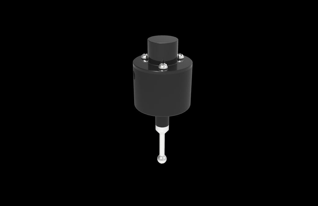
3 Box Contents Next Wave Automation Touch Probe Manual Attachment Arm Attachment Screw Alignment Pin Touch Probe General The Touch Probe The Next Wave Automation Touch Probe is an accessory for Next Wave Automation CNC machines. It is currently compatible with the Piranha XL and the Shark HD4. These machines have both the hardware and software to support the use of these probes. Using these probes allows for easily finding the center of an object placed on your CNC machine. The Touch Probe can find the center point of an object, or its center along either the X or Y axes. Setup The Attachment Arm included with the Touch Probe is how the probe is attached to your CNC machine. The Piranha XL and Shark HD4 have two holes on the side of the cradle the router is placed into (see image on page 2). The hole closest to the machine s front is tapped, and meant for the Attachment Screw included with the probe. The hole towards the back of the machine is not tapped, and is meant to hold the Alignment Pin. The Attachment Arm has four holes. Select one of the two rows of holes on the Attachment Arm to use. When attached, the tip of the Touch Probe should be lower than your router s bit when the router is mounted on the CNC machine. Once you have chosen which row of holes to use, push the Alignment Pin all the way into the Attachment Arm. You should use the hole that does not go all the way through the Attachment Arm for this. V September 2016 Touch Probe 1


4 Touch probe and attachment arm Next, place the other end of the Alignment Pin into the appropriate hole on your CNC machine. Use the Attachment Screw in the remaining hole to fully secure the Attachment Arm to your CNC machine. Securing the attachment arm V September 2016 Touch Probe 2
5 The Touch Probe snaps magnetically into the hole at the tip of the Attachment Arm. When attaching and removing the Touch Probe from the Attachment Arm, do not pull on the stainless steel tip of the Touch Probe. How to Use The Touch Probe can be used to automatically find the center of material placed onto a CNC machine. Once the touch probe is fully secured to the Attachment Arm, power on your CNC Controller. Plug the Touch Probe into your CNC Controller only after the Controller has powered on. Press the Apps button from the main menu on the CNC Controller. From there, select Center Finder. The Center Finder menu has 3 functions and three settings: Functions Find Center Both X & Y o Find the center of an object, using both length and width Find Center X Width o Find the center of an object along the X axis, ignoring length, using only width Find Center Y Length o Find the center of an object along the Y axis, ignoring width, using only length Settings Probing Speed o The speed at which the Touch Probe is moved while running a function Probe to Bit Offset X o The distance between the router bit and the tip of the Touch Probe along the X axis Probe to Bit Offset Y o The distance between the router bit and the tip of the Touch Probe along the Y axis The Probe to Bit Offset values need to be set from this menu before the Touch Probe is used. These values may vary slightly between each CNC machine. To determine these values, follow these steps: V September 2016 Touch Probe 3
6 Finding the Probe Offset Values The distance between the probe and the center of the router is the bit offset. Only the X and Y values need to be set. The difference in height (the Z value) between the probe and the router is irrelevant. In order to find the correct values to use, you must first find and mark the center of a piece of material. V September 2016 Touch Probe 4


7 Use the Center Finder function of the Touch Probe. Ensure that the tip of the Touch Probe is over the center of the material. Using the Center Finder function Zero the position of the router. Press the Zero xyz button in order to zero the router s current position across all values X, Y, and Z. Zeroing the router position V September 2016 Touch Probe 5


8 Move the Router so the bit is directly above the marked center of the material. Record the new position of the router. Due to the location of the Attachment Arm in relation to the router, the X and Y values should be made positive. These X and Y values are the Bit Offset X and Bit Offset Y values, respectively. YOUR X AND Y VALUES MAY BE DIFFERENT FROM THOSE SHOW IN THIS EXAMPLE PICTURE. USE ONLY THE VALUES FOR X AND Y SHOWN ON YOUR TOUCH-SCREEN CONTROLLER. V September 2016 Touch Probe 6

9 Enter these values to the Probe to Bit Offset X and Probe to Bit Offset Y. Your values that you get should be close to the following values. Due to variances in plastic thickness, your numbers may not be these exactly. Piranha XL Probe to Bit Offset X ~3.1 Probe to Bit Offset Y ~0.75 Shark HD4 Probe to Bit Offset X ~3.35 Probe to Bit Offset Y~ 0.75 V September 2016 Touch Probe 7
10 Troubleshooting The Touch Probes should consistently work for the Center Finder. In the event that the Touch Probe is not functioning as intended, here are some possible solutions: The Touch-Screen Display is displaying this message on startup when using the Touch Probe Possible Solution: Turn off your CNC Controller. Ensure that the cable between the Touch- Screen Display and the CNC Controller is secured on both ends. Ensure that the Touch Probe is not plugged into the CNC Controller. Turn your CNC Controller on. V September 2016 Touch Probe 8

11 While running the Center Finder function, the Touch Probe moves with the CNC machine, but it is not registering contact with the material OR The Touch-Screen Display is displaying this message when attempting to run the Center Finder function Possible Solution: STOP THE CNC MACHINE. The tip of the Touch Probe is kept in position by an internal spring that keeps it aligned. The spring may be stuck before the probe is worn in. Remove the Touch Probe from the Attachment Arm. Hold the stainless steel tip of the Touch Probe and push it gently up inside the probe. Let the spring push the tip of the Touch Probe back down. Reattach the Touch Probe to the Attachment arm. THIS IS THE ONLY TIME YOU SHOULD PUSH ON THE TIP OF THE TOUCH PROBE For any other issues you may have, please contact Next Wave Automation Technical Support: (419) V September 2016 Touch Probe 9
12 Warnings Do not pull or push on the stainless steel tip Do not pull or push on cord attached to the Touch Probe Do not remove the top of the Touch Probe Plug the Touch Probe into your CNC Controller only after the Controller has powered on FOR THE MOST RECENT MANUALS, DRIVERS, AND OTHER SOFTWARE, PLEASE VISIT V September 2016 Touch Probe 10
Monitor mount for 2016 E-series and E2417H Dell monitors. Installation guide
 Monitor mount for 2016 E-series and E2417H Dell monitors Installation guide Notes, cautions, and warnings NOTE: A NOTE indicates important information that helps you make better use of your product. CAUTION:
How to Calibrate a CNC Machine's Positioning System
 How to Calibrate a CNC Machine's Positioning System Guide to calibrating the Haas wireless intuitive probing system. Written By: Kim Payne 2018 gunnerautomotive.dozuki.com/ Page 1 of 20 INTRODUCTION Attention:
Dozuki. Written By: Dozuki System. Guide to calibrating the Haas wireless intuitive probing system. How to Calibrate WIPS
 Dozuki How to Calibrate WIPS Guide to calibrating the Haas wireless intuitive probing system. Written By: Dozuki System 2017 www.dozuki.com Page 1 of 22 INTRODUCTION Getting Started On initial setup or
Legacy Woodworking Machinery a division of Phantom Engineering. The Legacy CNC. Assembly Manual
 Legacy Woodworking Machinery a division of Phantom Engineering The Legacy CNC Assembly Manual New Orientation of the Legacy Step one: Re-orientation of the machine Remove the X-axis screw and supports.
Using the Bluetooth DRO display
 The premier source of tooling, parts, and accessories for bench top machinists. Using the Bluetooth DRO display Getting started The Android tablet included with your DRO has the SIEG DRO app preinstalled.
4th Axis OWNERS MANUAL
 4th Axis OWNERS MANUAL Copyright Next Wave Automation All Rights Reserved. Version 3.0 March 31, 2017 Updates of this manual are available at www.nextwaveautomation.com. *Information in this manual is
Cable Tray Kit: - Cable Tray - Cable Tray Cover - Power Block Support (x2) Top Support Kit: (x2) - 2 Top Supports. Quantities are per bench
 Top Support Kit: (x2) - 2 Top Supports. Quantities are per bench") Parts Included (per back to back bench) Column Kit: (x2) - 1 LH & 1 RH Column - Control Box - Hand Switch Cable Tray Kit: - Cable Tray - Cable Tray Cover - Power Block Support (x2) Depth Support Kit: -
Parts Included (per back to back bench) Column Kit: (x2) - 1 LH & 1 RH Column - Control Box - Hand Switch Cable Tray Kit: - Cable Tray - Cable Tray Cover - Power Block Support (x2) Depth Support Kit: -
Installation and Assembly - Universal Articulating Swivel Double-Arm for 42" - 60" Plasma Screens
 Installation and Assembly - Universal Articulating Swivel Double-Arm for 42" - 60" Plasma Screens Models: PLAV 70-UNL, PLAV 70-UNL-S PLAV 70-UNLP, PLAV 70-UNLP-S R This product is UL Listed. It must be
RMD3000 DPO3000 Series Rackmount Kit
 Instructions RMD3000 DPO3000 Series Rackmount Kit 071-2424-00 Warning The servicing instructions are for use by qualified personnel only. To avoid personal injury, do not perform any servicing unless you
Installing the 3 Indexer: PRS Standard Tools
 888-680-4466 ShopBotTools.com Installing the 3 Indexer: PRS Standard Tools Copyright 2016 ShopBot Tools, Inc. page 1 Copyright 2016 ShopBot Tools, Inc. page 2 Table of Contents Route Cable into Box...5
FLATFROG MULTITOUCH 3200
 FLATFROG MULTITOUCH 3200 Quick Assembly Guide Document Number LZN 100013 R1B Issue 2012-07 Industrial Design Casing Parts List b a Package contents Industrial design casing. The following items are included:
Installation Manual REbus Beacon. Part of the Pika Energy Island M
 Installation Manual REbus Beacon Part of the Pika Energy Island M00020-01 REbus Beacon Serial Number: RCP Number: We are committed to quality and constant improvement. All specifications and descriptions
PROFESSIONAL FLARING TOOL 001ERL 37 & ERL 37
 PROFESSIONAL FLARING TOOL 001ERL 37 & 45 002ERL 37 001ERL shown here OWNER S MANUAL 199R11215 EDUCATIONAL TIPS Make sure the end of the tube is cut off square. Before flaring, make sure the die clamp is
RMD2000 DPO2000 and MSO2000 Series Rackmount Kit Instructions
 xx ZZZ RMD2000 DPO2000 and MSO2000 Series Rackmount Kit Instructions Warning The servicing instructions are for use by qualified personnel only. To avoid personal injury, do not perform any servicing unless
Shepherd 210A Fingerprint Door Lock Installation Manual V1.1
 Shepherd 210A Fingerprint Door Lock Installation Manual V1.1 Hongda USA Inc. 2505 Technology Dr. #2-6A, Hayward, CA 94545, USA Phone: (510) 887-5682 Fax: (510) 372-0487 Email: info@hongdausa.com Website:
ROMAN AND. Roller Lift System Continuous Cord Loop GETTING STARTED BRACKET INFORMATION INSIDE MOUNT. A few simple tools are required:
 ROMAN AND WOVEN WOOD SHADES Roller Lift System Continuous Cord Loop GETTING STARTED BRACKET INFORMATION A few simple tools are required: The brackets you received with your product are REQUIRED for proper
Solar & Roller Shades
 STEP BY STEP INSTALLATION INSTRUCTIONS Solar & Roller Shades Cordless Control with Mounting Bar or Cordless Control with Cassette Table of Contents Step 1 - Getting Started.... 3 Everything You Need A
Assembly and Installation Guide
 The Easy Hang Closet Solution SM Install Your elfa In An Instant. Enjoy The Benefits For A Lifetime. Basic Tools For elfa Assembly and Installation Level Hand or Power Drill Drill Bits 1/8", 3/8", 5/16"
Monitor mount for 2017 P-series Dell monitors. Installation guide
 Monitor mount for 2017 P-series Dell monitors Installation guide Notes, cautions, and warnings NOTE: A NOTE indicates important information that helps you make better use of your product. CAUTION: A CAUTION
Small Above Fireplace Pull-Down Full-Motion TV Wall Mount
 Small Above Fireplace Pull-Down Full-Motion TV Wall Mount P/N 33123 User's Manual CONTENTS SAFETY WARNINGS AND GUIDELINES... 3 INTRODUCTION... 4 FEATURES... 4 CUSTOMER SERVICE... 4 PACKAGE CONTENTS...
Motorized or Crank Operated Fortress Zipper Track Shade with Housing and Side Track Installation Instructions
 Motorized or Crank Operated Fortress Zipper Track Shade with Housing and Side Track Installation Instructions Tools Needed Drill 3/8 Metal Drill Bit ¼ Masonry Drill Bit Measuring Tape Pencil 4 Level Phillips
Chicago Electric MIG B Gun Install
 Chicago Electric MIG 180 81295B Gun Install Step 1 First you will need to remove all the side panels on your machine. This is necessary to access everything for this install. Step 2 On the side with your
Copyright Next Wave Automation All Rights Reserved. Version April 2015
 Copyright Next Wave Automation All Rights Reserved. Version 2.1.0 11 April 2015 Updates of this manual may be available at www.nextwaveautomation.com. CNC Shark, CNC Shark Pro, CNC Shark Pro Plus, CNC
Sentinel Series Cigar Humidor End Tables
 Sentinel Series Cigar Humidor End Tables Assembly Instructions Models: Sentinel 500, 1000 and 1500 Style: Contemporary SENTINEL ASSEMBLY INSTRUCTIONS Congratulations! You have purchased a superior cigar
HydroFORM Phased Array Corrosion Mapping System Part 2 Mechanical Setup
 HydroFORM Phased Array Corrosion Mapping System Part 2 Mechanical Setup HydroFORM Corrosion Mapping System Mechanical Setup The HydroFORM Phased Array System is designed to perform corrosion mapping in
Installation and Assembly - Universal Articulating Swivel Double-Arm for 42" - 60" Plasma Screens
 Installation and Assembly - Universal Articulating Swivel Double-Arm for 42" - 60" Plasma Screens Models: PLAV 70-UNL, PLAV 70-UNL-S PLAV 70-UNLP, PLAV 70-UNLP-S R This product is UL Listed. It must be
PERSONAL RECORD KEEPING
 2 P R O 3 7 0 A s s e m b l y i n s t r u c t i o n s PERSONAL RECORD KEEPING Tip: Record the serial numbers of your Octane Fitness elliptical in the spaces below. This will make it easier for you to obtain
PRS X-Axis E-Chain Installation For Tools with a 12 Z-Axis
 888-680-4466 ShopBotTools.com PRS X-Axis E-Chain Installation For Tools with a 12 Z-Axis This kit is compatible with PRS Shopbots that have an X-axis cutting area of 96 to 144. It is not immediately compatible
Vinyl Cutter Instruction Manual
 Vinyl Cutter Instruction Manual 1 Product Inventory Inventory Here is a list of items you will receive with your vinyl cutter: Product components (Fig.1-4): 1x Cutter head unit complete with motor, plastic
Solar & Roller Shades
 STEP BY STEP INSTALLATION INSTRUCTIONS Solar & Roller Shades Cordless Control with Mounting Bar or Cordless Control with Cassette Everything You Need A Smooth Set-Up We want you to love your new window
TM Quick Start Guide
 TM Quick Start Guide Contacting Pazzles By Phone In the US: 866-729-9537 International: +1-208-922-3558 Phone Hours: Mon - Fri, 9am - 5pm Mountain Time By Email Customer Service: Technical Support: Sales:
Rotary Fixture M/V/X CLASS LASER SYSTEMS. Installation and Operation Instructions
 Rotary Fixture M/V/X CLASS LASER SYSTEMS Installation and Operation Instructions 02/01/2000 Introduction The Rotary Fixture controls in the Printer Driver are used along with the optional Rotary Fixture
Custom Grille Insert
 1 of 8 Thank you for your purchase of DBCustomz 2016+ Toyota Tacoma! This product was carefully crafted to ensure a perfect fit with your vehicle. The instructions below are provided to allow for an easier
7878 K940. Checkpoint Antenna. Kit Instructions. Issue B
 7878 K940 Checkpoint Antenna Kit Instructions Issue B Revision Record Issue Date Remarks A July 7, 2009 First issue B Nov2013 Revised the Checkpoint installation procedures for 7878 and 7874 scanners Added
ABM International, Inc.
 ABM International, Inc. Lightning Stitch required 1 1.0: Parts List head and motor assembly (Qty. 1) Reel stand (Qty. 1) Needle bar frame clamp (Qty. 1) Motor drive (Qty. 1) 2 Cable harness with bracket
Sentinel Series Cigar Humidor End Tables
 Sentinel Series Cigar Humidor End Tables Assembly Instructions Models: Sentinel 500, 1000 and 1500 Style: Traditional SENTINEL ASSEMBLY INSTRUCTIONS Congratulations! You have purchased a superior cigar
Transition Range Installation, Care & Adjustment Instructions
 Introduction The following instructions will enable you to complete the final assembly and adjustment of your new furniture. Hardware Box Each of the cabinets contains a Hardware box that contains all
ADJUST-A-VIEW QUARTER CIRCLE INSTALLATION INSTRUCTIONS
 Omega Mfg. Corporation Two Rivers, WI (800) 874-9594 www.adjustaview.com Proudly Serving Customers Since 1976 Page 1 of 5 MATERIAL LIST ADJUST-A-VIEW User Instructions ADJUST-A-VIEW Installation Instructions
Keypad Lock Retrofit Kit for Follett REF Undercounter Refrigerator P/N
 Materials supplied Reference # Keypad assembly (housing and mounting base) 1 Keypad housing base 2 Lock mechanism with cable 3 (9) 8-32 x 1/2" stainless steel screws 4 Latch 5 Jig 2, latch 6 Jig 1, keypad
COIL BINDING SYSTEM 3000
 COIL BINDING SYSTEM 3000 SETUP & OPERATOR MANUAL Performance Design LLC 2350 East Braniff St. Boise, Idaho 83716 www.rhin-o-tuff.com Office Elite Series Coil Binding System 3000 FEATURES: Open-ended Punch
Cover Page. Factory Radio Other Documents Available For This Vehicle:
 Factory Radio Other Documents Available For This Vehicle: No documents available at this time Adobe Acrobat Reader Printing Tips: 1) Select FLE then PRNT and select your printer. 2) n the print options
Hatch Whiteboard: Portable Stand Installation Instructions
 Hatch Whiteboard: Portable Stand Installation Instructions Remove Projector Wall Plate 1. Open the wall mount for the projector. 2. Remove the shipping screw from the front center of the mount arm. 1 P
Start Here. Installing your Microtek ScanMaker 9800XL Plus PC:
 Start Here Installing your Microtek ScanMaker 98XL Plus Step : Unpack Contents. Optional package items depend on the scanner configuration that you purchased. Unpack your scanner package and check for
SERVICE MANUAL AND PARTSLIST
 SERVICE MANUAL AND PARTSLIST Next 20 CONTENTS WHAT TO DO WHEN... 1~3 SERVICE ACCESS FACE COVER... 4 TOP COVER... 4 BASE COVER... 5 REAR COVER... 6 FRONT COVER... 7 MECHANICAL ADJUSTMENT NEEDLE THREAD TENSION...
BMW X5 OEM RUNNING BOARD PART#SBBW
 INSTALLATION INSTRUCTIONS 2014-2016 BMW X5 OEM RUNNING BOARD PART#SBBW-146-74 QTY HARDWARE 1 Driver Side OEM Running Board 1 Passenger Side OEM Running Board 8 Rivet Pin 1 Page Step 1: Verify all parts
Wall Mount Assembly and Mounting Guide (55 /84 )
") Microsoft Surface Hub Wall Mount Assembly and Mounting Guide (55 /84 ) For mounting on a wall with wood studs These instructions assume wood-stud wall construction with 2-by-4 studs spaced 16 inches apart,
Microsoft Surface Hub Wall Mount Assembly and Mounting Guide (55 /84 ) For mounting on a wall with wood studs These instructions assume wood-stud wall construction with 2-by-4 studs spaced 16 inches apart,
BL-ER-P Ethernet Radio Unit for Pedestal Installation Guide
 Assemble the Antenna Riser 1. Remove the antenna riser assembly and the antenna from its packaging. 2. Remove the plastic cap, the nut, and the lock washer from the stem of the antenna. 3. Put the stem
Iphone 5 Glass/Lcd REPAIR GUIDE. Version Edition
 Iphone 5 Glass/Lcd REPAIR GUIDE Version 1 2016 Edition IPhone 5 Glass/LCd REPAIR GUIDE RiAna Soto Repair Training Specialist rsoto@cellairis.com FOR EVERY REPAIR MAKE SURE TO COMPLETE, INITIAL, AND HAVE
This document will provide detailed specifications, BOM information, and assembly instructions for the Official Competition Field.
 This document will provide detailed specifications, BOM information, and assembly instructions for the Official Field. Teams who do not need an official field should refer to the separate low-cost field
Dynamic Nanospray Probe (NSI-1) Installation Guide
 Installation Guide") Dynamic Nanospray Probe (NSI-1) Installation Guide This guide describes how to install the NSI-1 dynamic nanospray probe (see Figure 1) onto a TSQ Series or LTQ Series mass spectrometer and provides general
Dynamic Nanospray Probe (NSI-1) Installation Guide This guide describes how to install the NSI-1 dynamic nanospray probe (see Figure 1) onto a TSQ Series or LTQ Series mass spectrometer and provides general
Please read BOTH these Installation Instructions and the General Instructions prior to installing or operating this equipment.
 Attachment Tab Height: 16-1/4 Attachment Tab Width: 21-3/4 Please read BOTH these and the General Instructions prior to installing or operating this equipment. Serial Number 1. Blue Ox towing products
COLOR LASERJET PRO MFP. Repair Manual
 OK COLOR LASERJET PRO MFP Repair Manual X M76 M77 HP Color LaserJet Pro MFP M76, M77 Repair Manual Copyright and License 03 Copyright Hewlett-Packard Development Company, L.P. Reproduction, adaptation,
The wick in your heater needs replacing if, after repeated cleanings, any of the following conditions still exist:
 WICK REPLACEMENT The wick in your heater needs replacing if, after repeated cleanings, any of the following conditions still exist: Slow to light, hard movement of the wick adjuster knob, kerosene odor
HONEYCOMB SHADES with Continuous Cord Loop
 HONEYCOMB SHADES with Continuous Cord Loop GETTING STARTED BRACKET INFORMATION A few simple tools are required: The brackets you received with your product are REQUIRED for proper installation. Brackets
Wall mounting bracket
 Install Manual Wall mounting bracket Please read this manual carefully before operating your set and retain it for future reference. OSW200 P/NO : MFL63640578 (1502-REV01) www.lg.com COMPONENT Install
Installers guide Deadbolt 02.
 Installers guide Deadbolt 02. version 0.7.1 Specifications Model igloohome Smart Deadbolt 02 Material Zinc Alloy Current Rating (Standby) ~30uA Current Rating (Active) ~200mA Batteries 4 x AA Alkaline
Compact Router Ellipse/ Circle Jig Instructions
 Compact Router Ellipse/ Circle Jig Instructions The Compact Router Ellipse/Circle Jig allows you to use your compact plunge router to easily cut precise ellipses and circles for picture frames, mirrors,
OB1U INSTALLATION INSTRUCTIONS. Interactive Flat Panel Over White Board Mount
 INSTALLATION INSTRUCTIONS Interactive Flat Panel Over White Board Mount Spanish Product Description German Product Description Portuguese Product Description Italian Product Description Dutch Product Description
Sole Fitness E95 Elliptical Trainer TurnKey Delivery and Setup Training
 Sole Fitness E95 Elliptical Trainer TurnKey Delivery and Setup Training Delivery Requirements Ground delivery Inside delivery to customer-specified location Unpack and assemble machine, and remove packing
MultiTable Mod-E 2 Electric Standing Desk
 The Height of Healthy Design MultiTable Mod-E 2 Electric Standing Desk ASSEMBLY INSTRUCTIONS MultiTable Mod-E 2 Electric Standing Desk Frame PARTS AND TOOLS PLEASE REVIEW these instructions before beginning
Content. Before You Start. Assemble the 3D Printer. Use the 3D Printer. Load Filament Level the Heated Bed Start Printing Support
 Quick Start Guide Content A Before You Start B Assemble the 3D Printer C Use the 3D Printer Load Filament Level the Heated Bed Start Printing Support 2 Before You Start Get the Screwdriver Ready The screwdriver
Setting Part Zero and Setting Cutting Tool for Wheel Lathe
 There are three sections in this document: A: Setting Tool #1 and Tool #2 on center line height to the spindle which are explained in steps 1 thru 3 B: Setting Part 0 for X & Z and setting X & Z reference
MODEL T27697 & T " & 8" HELICAL CUTTERHEADS INSTALLATION INSTRUCTIONS
 MODEL T27697 & T27699 6" & 8" HELICAL CUTTERHEADS INSTALLATION INSTRUCTIONS For questions or help with this product contact Tech Support at (570) 546-9663 or techsupport@grizzly.com These indexable insert
Measuring Nitrate in Water and Wastewater using the Thermo Scientific Orion Dual Star ph/ise Meter
 Measuring Nitrate in Water and Wastewater using the Thermo Scientific Orion Dual Star ph/ise Meter Water and Lab Products, Thermo Fisher Scientific Technical Note 503 Key Words Thermo Scientific Orion
Assembly Guide for Printrbot - Simple Maker s Edition 1405
 Assembly Guide for Printrbot - Simple Maker s Edition 1405 Last update: March 2016 Please Note: be careful on the steps that are underlined 1 Contents Tools Needed:... 3 First step: Check components and
ADJUST-A-VIEW HALF CIRCLE INSTALLATION INSTRUCTIONS
 Omega Mfg. Corporation Two Rivers, WI (800) 874-9594 www.adjustaview.com Proudly Serving Customers Since 1976 Page 1 of 7 MATERIAL LIST ADJUST-A-VIEW User Instructions ADJUST-A-VIEW Installation Instructions
Installing Brackets to Minimize Distortion in Your SMART Board 685ix Interactive Whiteboard System s Projected Image
 UX60-RFK-685 Installing Brackets to Minimize Distortion in Your SMART Board 685ix Interactive Whiteboard System s Projected Image Follow these instructions to install brackets on your SMART Board 685ix
Finding Offsets for Multiple Spindles/Air Drills
 888-680-4466 ShopBotTools.com Finding Offsets for Multiple Spindles/Air Drills Copyright 2016 ShopBot Tools, Inc. page 1 Copyright 2016 ShopBot Tools, Inc. page 2 Introduction This document explains how
Yes 20 Charging Wall Cabinet for Tablets
 Built with Anthro-DNA Owner's Manual for Yes 20 Charging Wall Cabinet for Tablets Part # YESCABGMPW Components at a Glance 1 2 4 5 8 7 10 3 6 9 Front of Cabinet (closed) 1. Locking front door to User area.
NEX-2X-PROBE. Back to back mounting hardware for use with the Tektronix P6860/80/64 or P6419 Probes
 NEX-2X-PROBE Back to back mounting hardware for use with the Tektronix P6860/80/64 or P6419 Probes Reduces by 50% the circuit board area needed to probe 34 channels Uses only two retaining holes to hold
Installing and Upgrading Internal Modules in Cisco 1800 Series Routers (Modular)
") CHAPTER Installing and Upgrading Internal Modules in Cisco 800 Series Routers (Modular) This chapter describes how to install or upgrade modules that are located internally within the Cisco 800 series
CHAPTER Installing and Upgrading Internal Modules in Cisco 800 Series Routers (Modular) This chapter describes how to install or upgrade modules that are located internally within the Cisco 800 series
Z-Truck Up-and-Down Motion. Y-Truck Side-to-Side Motion. Head. Squaring Plate. Sliding Plate FIGURE 1: THE CARVEWRIGHT MACHINE
 Setup and use of CarveWright CO2 Powered Dragster Jig The CO 2 powered Dragster Jig will arrive from the factory fully assembled, calibrated, and squared. In order to get the best results, your CarveWright
INSTALL/REMOVAL INSTRUCTIONS: WINDOW REGULATOR
 REMOVAL/INSTALL OF WINDOW REGULATOR (741-584) Ford Focus 2000-2007 General Tech Tips: Use painter s tape rather than duct tape to secure window. It will not damage paint or leave sticky residue. A plastic
A. Preparing the fabric (not shown):
:") INSERTING ZIPPERS - CENTER INSERTION The zipper can be snapped on to the right or to the left side of the needle so that you can sew close to the zipper. When sewing on the right side of the zipper, attach
INSERTING ZIPPERS - CENTER INSERTION The zipper can be snapped on to the right or to the left side of the needle so that you can sew close to the zipper. When sewing on the right side of the zipper, attach
Standard Nagel M2 Bookletmaker Operators Manual
 1-800-543-5454 (801) 927-3026 Standard Nagel M2 Bookletmaker Operators Manual Read this manual, and thoroughly familiarize yourself with its contents before operating or servicing the equipment TABLE OF
STEP 1 : DESTROYER FRONT BUMPER INSTALL GATHER YOUR TOOLS AND LAY OUT YOUR PARTS... *shorty bumper to show hardware* Tools Required:
 DESTROYER FRONT BUMPER INSTALL JL STEP 1 : GATHER YOUR TOOLS AND LAY OUT YOUR PARTS... Tools Required: - Utility knife - 11/16 Deep socket - Ratchet - 11/16 Crescent wrench - Ratchet Extension - 1/4 socket
AGS-XP-250. AGS Sensor Tip FOR THE AGS-SB170 SENSOR DESCRIPTION. dametric. AGS-XP-250_Eng.docx Oct. 7, 2010 / JO / BL Page 1 (6)
") AGS-XP-250 AGS Sensor Tip FOR THE AGS-SB170 SENSOR dametric AGS-XP-250_Eng.docx Oct. 7, 2010 / JO / BL Page 1 (6) CONTENT 1 GENERAL... 2 2 SPECIFICATION... 2 3 SEALING... 3 4 TIP EXCHANGE... 3 5 ADJUSTING
AGS-XP-250 AGS Sensor Tip FOR THE AGS-SB170 SENSOR dametric AGS-XP-250_Eng.docx Oct. 7, 2010 / JO / BL Page 1 (6) CONTENT 1 GENERAL... 2 2 SPECIFICATION... 2 3 SEALING... 3 4 TIP EXCHANGE... 3 5 ADJUSTING
Scratch Assay Device for Wound Healing Studies
 Scratch Assay Device for Wound Healing Studies By Team Cell Scratcher: Hannah Morgan, Charles Merchant, and Zachariah Cribbin 1 Quick Start Guide 2 Comments: _ Table of Contents Cover Page 1 1.0 Quick
ASSEMBLY INSTRUCTIONS. enook Pro
 ASSEMBLY INSTRUCTIONS enook Pro Product enook Pro for Monitors, 36w Part# EPM3616zz/xx Anthro Corporation 10450 SW Manhasset Dr. Tualatin, OR 97062 Toll-free: 800.325.3841 Fax: 800.325.0045 email: sales@anthro.com
DFG E-TitanComb Heavy Duty Binding Machine
 DFG E-TitanComb Heavy Duty Binding Machine Instruction Manual Provided By http://www.mybinding.com http://www.mybindingblog.com EtitanComb Machine Operation Manual For your safety: 1. Do not connect this
HQ Electromagnetic Channel Locks
 HQ Electromagnetic Channel Locks Table of Contents Overview... 2 Kit Contents... 2 Tools Required... 5 Installation... 5 Using the HQ Electromagnetic Channel Locks... 10 Troubleshooting... 11 Overview
7902 Dado Jig. Owners Manual Please Read Carefully! Hardware List: 7902 Parts List:
 7902 Dado Jig Owners Manual Please Read Carefully! 7902 Dado Jig Hardware List: Identify and verify that you have all of the hardware shown below prior to assembly. Please read the instructions at least
Woodline USA Woodline Spacer Fence System
 Woodline USA Woodline Spacer Fence System MADE IN THE USA Includes: (1) ¼ Spacer Fence (1) 3/8 Spacer Fence (1) ½ Spacer Fence (1) Hardware Package (1) 3 Piece Brass bar set (2) Setup Blocks Visit Us Online
Please read BOTH these Installation Instructions and the General Towing Instructions before attempting to install or operate this equipment.
 2005-08 Pontiac G6 GT Please read BOTH these and the General Towing Instructions before attempting to install or operate this equipment. 1. Blue Ox towing products and accessories are intended to be installed
1. ASSEMBLING THE PCB 2. FLASH THE ZIP LEDs 3. BUILDING THE WHEELS
 V1.0 :MOVE The Kitronik :MOVE mini for the BBC micro:bit provides an introduction to robotics. The :MOVE mini is a 2 wheeled robot, suitable for both remote control and autonomous operation. A range of
Quill Stop V2 Installation Guide 11/16/2014
 Thank you for purchasing the Quill Stop for the Sieg X3 (Grizzly G0463) and SX3 (Grizzly G0619) mills. Your feedback is always appreciated. Please email questions and comments to gregpriest@cox.net. What
VIEWPOINT ALUMINUM RUNNING BOARD TOYOTA RAV4
 PARTS LIST: VIEWPOINT ALUMINUM RUNNING BOARD 1 Driver/Left Running Board 4 10-1.5mm x 50mm T-Bolt 1 Passenger/Right Running Board 12 10mm Plastic Retainers 1 Driver/Left Bracket 2 10-1.50mm x 40mm Hex
Bluetooth DRO Installation for Bench Mills
 The premier source of tooling, parts, and accessories for bench top machinists. Bluetooth DRO Installation for Bench Mills These instructions describe how to install the following products: 5494: Digital
TIRE RACK INSTALLATION INSTRUCTIONS Dodge Sprinter
 Aluminess Products Inc 9402 Wheatlands Ct. #A Santee, CA 92071 619-449-9930 TIRE RACK INSTALLATION INSTRUCTIONS 07-11 Dodge Sprinter Please read before beginning Stainless steel hardware may bind together
RAILING. Installation Guide
 RAILING Installation Guide THE BEST CHOICE FOR STRONG & DURABLE RAILING SYSTEMS Our exclusive manufacturing process ensures our vinyl railing will provide superior strength plus it is virtually maintenance
Standard Operating Procedure of Atomic Force Microscope (Anasys afm+)
") Standard Operating Procedure of Atomic Force Microscope (Anasys afm+) The Anasys Instruments afm+ system incorporates an Atomic Force Microscope which can scan the sample in the contact mode and generate
Standard Operating Procedure of Atomic Force Microscope (Anasys afm+) The Anasys Instruments afm+ system incorporates an Atomic Force Microscope which can scan the sample in the contact mode and generate
Figure A. Figure B. Figure C. Figure D
 Xsite 1 Power/Data Tile and Components Tools Required Tape Measure Cordless Drill/Driver #2 Phillips Screw driver bit Rubber Mallet Flat Blade Screwdriver Figure A Hardware Required Provided as shown Installation
Automatic Tool Changer (ATC) for the prolight A Supplement to the prolight 1000 User s Guide
 for the prolight A Supplement to the prolight 1000 User s Guide") Automatic Tool Changer (ATC) for the prolight 1000 A Supplement to the prolight 1000 User s Guide 1 1995 Light Machines Corporation All rights reserved. The information contained in this supplement (34-7221-0000)
Automatic Tool Changer (ATC) for the prolight 1000 A Supplement to the prolight 1000 User s Guide 1 1995 Light Machines Corporation All rights reserved. The information contained in this supplement (34-7221-0000)
Installation and Assembly - Articulating Swivel Double-Arm for 42" - 71" Plasma Screens
 Installation and ssembly - rticulating Swivel Double-rm for 42" - 71" Plasma Screens Models: PLV 70, PLV 70-S R This product is UL Listed. It must be installed by a qualified professional installer. Maximum
RH-412 STEEL DOORS INSTALLATION INSTRUCTIONS
 RH-412 STEEL DOORS INSTALLATION INSTRUCTIONS By following the steps outlined below, the assembly, installation and adjustment of the steel doors, will be a simple process. Let s start with the Driver Side.
Fig. 2 DORMA-Glas Stand/Issue 02/03 Seite/Page 1/7
 FSW Installation instructions Track rail 75 x 72 mm 1. Ceiling substructure and installation of the track rail (Fig. 1): The track rail must be bolted over its entire length (including the stacking track
Ohbot. Eyes turn. servo. Eyelids open. servo. Head tilt. servo Eyes tilt. servo. Mouth open servo. Head turn servo
 Making Instructions Ohbot Ohbot has six servo motors. The servos allow each part of the face to be positioned precisely. Eyelids open servo Eyes tilt servo Eyes turn servo Head tilt servo Mouth open servo
INSTALLATION INSTRUCTIONS RH 412 STEEL DOORS
 By following the steps outlined below, the assembly, installation and adjustment of the steel doors, will be a simple process. Let s start with the Driver Side. Note: Having the hood open makes the job
so you want to get to know Onsrud... Onsrud1 : machine set up
 so you want to get to know Onsrud... Onsrud1 : machine set up What does CNC mean? CNC: Computer Numerical Control The router is controlled by a computer, that tells the router where to go through a series
Be Crafty. Technique Tutorial. How To Apply a Press Lock with Prongs PAGE 1
 PAGE 1 Totes, handbags and other accessories often need a secure closure. Something more than a hook & eye or snap, yet something that is visually appealing. Consider a press lock for quick and easy access,