Wall Mount Assembly and Mounting Guide (55 /84 )
|
|
|
- Dorcas Chase
- 6 years ago
- Views:
Transcription

1 Microsoft Surface Hub Wall Mount Assembly and Mounting Guide (55 /84 ) For mounting on a wall with wood studs These instructions assume wood-stud wall construction with 2-by-4 studs spaced 16 inches apart, covered with gypsum board. The supplied mounting screws are for use only in 1 / 2 or 5 / 8 thick gypsum board walls less than 10 feet high. For any other kind of wall, ask a professional installer for advice on the appropriate hardware and methods.
2 Important safety warnings Before assembling and mounting Microsoft Surface Hub on the wall mount, read these important safety warnings. This symbol identifies safety and health messages in this device guide. WARNING: Read safety and health information Read this guide for important safety and health information. Keep all printed guides for future reference. Failure to follow instructions and properly set up, use, and care for this product can increase the risk of serious injury or death, or damage to the device or devices. For an online version of this guide and additional support, safety, and health information, go to: WARNING: Installation experts knowledge Improper handling or installation could result in injury or death. To avoid hazards related to improper installation, ensure the installation is performed by people who have read and understand the installation instructions prior to beginning. In some cases, installation should be performed by trained and authorized installation professionals. It is the consumer s responsibility to ensure that the wall can properly support the total weight. WARNING: Minimum number of installers In order to reduce the risk of injury, Microsoft Surface Hub 55 requires a minimum of two people and Microsoft Surface Hub 84 requires a minimum of four people to perform the installation. WARNING: Proper mounting to wall To reduce the risk of the device falling, resulting in injury, death or damage to the device, ensure that: The wall strength and mounting method are appropriate to support the weight of this device. The included mounting hardware is designed for Surface Hub held by 2x4 wood studs with 1 / 2 or 5 / 8 gypsum board wall 10 feet high or lower. For other wall types, ask a professional installer for advice. Reinforcement might be necessary for some materials such as plaster/thin plastic board/wood before starting installation. If your wall is not 2x4 studs, 16 inches apart with 1 / 2 or 5 / 8 gypsum board 10 feet high or less, purchase the correct hardware to support the device in your installation. Use only wall mounts intended for use with the Surface Hub model you re mounting. Securely tighten all fasteners according to the instructions. Do not overtighten. WARNING: Proper installation environment To reduce risks related to the environment, the unit must be installed indoors only. It is the consumer s responsibility to ensure that structural engineering requirements for potential seismic activity are met per your local requirements. This may require wall reinforcement. Do not install near sources of high heat or steam or where condensation is likely to occur, such as near air conditioners. Do not install on a structure that is prone to vibration or movement.
3 Do not install in such a way as to block ventilation holes. Allow for proper ventilation according to the device specifications. Do not install in areas with potentially explosive atmospheres. These areas are often, but not always, posted and can include fueling areas, such as below decks on boats, fuel or chemical transfer or storage facilities, or areas where the air contains chemicals or particles, such as grain dust or metal powders. The device should not be used in these areas. In such areas, sparks can occur and cause an explosion or fire. WARNING: Handling and site preparation Do not attempt to install the device with fewer than the required number of individuals. To reduce the risk of injury due to the size and weight of the device, keep the device upright. When placing the device onto the mount, be certain it is properly seated before releasing it. Keep the assembly area clear of packing materials. Remove materials after each step. WARNING: Designated load capacity Wall mounts are rated for a designated load capacity. To reduce risk of personal injury, death or damage to the device, never exceed the designated load capacity of the wall mount. Refer to the specification section for weights and load capacities. WARNING: Tip-over and fall hazard The wall mount is designed to handle the weight of the device. To reduce the risk of injury or death, never allow anyone or anything to hang from the unit. Never suspend anything other than the designated device. WARNING: Do not attempt to repair or modify Assemble stand components using only fasteners provided by Microsoft, as shown on the parts list. Do not attempt to take apart, open, service, or modify the product, accessories, or power supply. Doing so could present the risk of electric shock or other hazard. Any evidence of any attempt to open and/or modify this device, including peeling, puncturing, or removing any of the labels, will void the Limited Warranty. Heed all warnings and follow all instructions. WARNING: Electrical outlet location To reduce risks related to electric shock, ensure that there is an appropriate electrical outlet within reach of the power cord provided with device to be mounted. Do not use extension cords, or a power cord other than what is provided with the display assembly. WARNING: Pinch hazard When mounting the wall support and installing the device, take care to avoid pinching fingers. WARNING: Choking hazard This device or its accessories may contain small parts, which may be a choking hazard to children under 3. Keep small parts away from children. WARNING: Small children This device and its accessories are not toys. To reduce the potential for injury, death, or product damage, do not allow small children to play with them. Never allow children to climb on or hang from the device or its stand. WARNING: Mounting surface orientation The wall mounting assembly is designed for vertical surfaces only. To reduce the risk of
4 injury or death, do not mount to any surface other than a vertical wall. Do not mount in any orientation other than landscape.
5 This guide outlines the steps for assembling the Surface Hub 55 and Surface Hub 84 wall mounts. These mounts require two people to assemble. Before you begin, make sure you have all of the components in the parts list. IMPORTANT: Avoid damage to your device. The Surface Hub 55 is intended to be supported only by its bottom edge when not supported by the mounting system. Rest it only on its bottom edge, and support it to keep it vertical. The Surface Hub 84 is intended to be supported only by the lifting handles when not supported by the mounting system. Do not place either device on its face, back, top, or sides. Specifications Model Device weight Mount weight Handle weight Designated load capacity Surface Hub lb. 25 lb. NA 135 lb. Surface Hub lb. 35 lb. 30 lb. 325 lb. Required tools (not included) #2 Phillips screwdriver 4mm hex key (Surface Hub 55 only) 5mm hex key (Surface Hub 84 only) 7/16-inch wrench Drill 3/32-inch drill bit Level Stud finder Tape measure Straightedge Eye protection
 Clamp Hanger Bar (2 each) Hanger Bar Screw (4 each) 55 Device:")
6 Parts list Images are not to scale. Top Hook Wall Plate (1 each) Clamp Hanger Bar (2 each) Hanger Bar Screw (4 each) 55 Device: M6x12 84 Device: M8x12 ¼ Lag screw (6 each) Washers (6 each)

. C. Use a level to make sure the wall plate is level. D.")
7 Assembly and mounting instructions Step 1: Attach the wall plate to the wall A. Mark the wall at the point where you want the center of your Surface Hub screen to be. Note: Microsoft recommends a center height of 55 inches for the Surface Hub 55 and a center height of 54 inches for the Surface Hub 84. Center Mark B. Place the wall plate against the wall, making sure the center mark indicator on the wall plate is over the center height mark you made on the wall. Note: The arrow on the center mark indicator should point up (see image above). C. Use a level to make sure the wall plate is level. D. When you re certain the wall plate is level, draw a line on the wall across the top of the wall plate, using its edge as a guide. E. After you draw the line, set the wall plate aside.


8 Center Mark Stud Mark Lines F. Using a stud finder, identify the three studs nearest the center mark on the wall. G. Indicate the stud locations by marking the wall above the horizontal line you drew using top of the wall plate. Make sure your marks are in the center of each stud. H. Make another mark 16 inches below each stud mark. Make sure your marks are in the center of each stud. I. Use a straightedge to draw lines between the upper and lower marks for each of the three studs. Note: The pattern should look like the image above. (Your center mark may be more to one side or the other.) J. Mark where the stud lines cross the horizontal slots in the wall plate. a. Place the wall plate against the wall. Align the center mark indicator on the wall plate with the center mark on the wall, making sure the arrow is pointing up and the wall plate is level. Drill here b. Mark the wall at each point where a horizontal slot in the wall plate crosses a vertical stud line on the wall (see image below). Note: If you can t see the line in the slot, move the wall plate left or right until you can.

9 c. Set the wall plate aside. WARNING: Stud alignment To reduce the risks related to fall hazards, ensure that the mount will attach to three studs and that the screws are mounted at the center of each stud. K. Loosely secure the wall plate to the left-hand stud. a. Drill a 3/32-inch pilot hole at the top mark in the center of the left-hand stud. b. Align the wall plate over the pilot hole. c. Place a washer on a lag screw and drive the lag screw into the pilot hole. Note: Leave the lag screw loose enough to allow the wall plate to move freely. WARNING: Hidden hazards Walls can contain electrical wires and other unseen hazards and obstacles such as water or gas lines. It is the installer s responsibility to locate and avoid these hazards during installation. If drilling and/or cutting into the mounting surface, always make sure that there are no electrical wires, water lines or gas lines in the wall. Cutting or drilling into any of these may cause serious injury or death. L. Secure the wall plate to the right-hand stud. a. Drill a 3/32-inch pilot hole at the top mark in the center of the right-hand stud. b. Align the wall plate over the pilot hole. c. Place a washer on a lag screw and drive the lag screw into the pilot hole. d. Using a level, make sure that the wall plate is level and that the center mark indicator on the wall plate still aligns with the center mark on the wall. e. Fully tighten both lag screws. M. Install the remaining four screws in the same way. Note: Make sure you align the screws with the vertical lines marking all three studs (see image below).
. B. Using the hanger bar screws, attach the hanger bar to the mounting screw holes. C.")
10 Step 2: Attach the hanger bars to the Surface Hub A. Place one of the hanger bars over the left mounting screw holes on the back of the Surface Hub. Note: Be sure to use the holes closest to the left edge of the display (see image below). B. Using the hanger bar screws, attach the hanger bar to the mounting screw holes. C. Tighten the screws securely, but do not overtighten. D. Repeat these steps with the right side hanger bar. WARNING: Ensure screws are securely tightened To reduce the risk of the product falling, ensure that all screws are securely tightened before mounting the display. Do not overtighten. Step 3: Hang the Surface Hub on the wall plate WARNING: Ergonomic lifting To reduce the potential for lifting related injuries, follow good ergonomic lifting guidelines. Ergonomic lifting guidelines Plan ahead. Ensure that everyone lifting the display knows the lifting plan and their role. Determine if you can lift the unit. Is it too heavy or too awkward? Decide if you need lifting aid.

11 Check your environment for obstructions and slippery surfaces. Make sure the lifting team agrees on the plan. Lift with your legs, not your back. Bend at your knees, keeping your back straight. Keep the unit close to your body. Center your body over the unit. Keep your feet about shoulder width apart. Lift straight up smoothly. Keep your torso straight; do not twist while lifting or after the load is lifted. Grasp the proper handhold locations as shown below. Set the unit onto the stand or wall mount slowly and smoothly with a straight back; Do not release your display panel until you are certain that it is properly seated. WARNING: To reduce the risk of injury or product damage, use only the handhold locations shown below for the Surface Hub 55. Lifting requires a minimum of two people. Person 1 Person 2 WARNING: To reduce risk of injury or product damage, use only the handhold locations shown below for the Surface Hub 84. Lifting requires a minimum of four people.
12 Person 1 Person 4 Person 2 Person 3

13 A. Confirm that the hanger bar clamps are open. Note: If the clamps are not fully open, turn the clamp screws counterclockwise to open them (see images below). Open Clamp Screw Clamp Open Clamp Closed

14 B. Lift the Surface Hub and align the top hooks of the hanger bars with the top edge of the wall plate (see image below). C. Lift the Surface Hub using the handhold locations shown above. Note: Be sure to use ergonomic lifting techniques. D. GENTLY lower the Surface Hub to seat the hanger bar hooks on the wall plate. Note: Do not release the device until you are sure the hanger bars are properly seated on the wall plate. E. Tighten the hanger bar clamp screws securely, but do not overtighten. Step 4: Remove the lifting handles (Surface Hub 84 only) Surface Hub 84 is shipped with the lifting handles already attached. Once the Surface Hub is mounted, remove the handles and keep them in case you ever need to take the Surface Hub off the wall mount. Top Hook Wall Plate Not Engaged Fully Engaged A. Remove the screws from the lifting handle mounting bars (see images below). a. Using a hex key, unscrew the screw that attaches the handle on the right side. b. Holding onto the right-hand mounting bar, unscrew the screw that attaches the handle on the left side. c. Set aside and store handles.
15
16 B. Depress the levers inside the lifting handle mounting bars, slide them into the device and close the plastic door covers (see image below). This image needs to be improved Press to release Close door


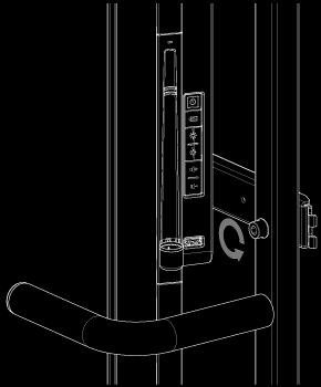
17 Step 5: Connect cables WARNING: 55 tilting feature To reduce potential pinch concerns, do not push on the face of the Surface Hub 55 while you are accessing the back of the system. WARNING: Cable routing To reduce risks related to electric shock or trip hazards, ensure cables are routed in such a way as to prevent them from being pinched, crushed, cut, or tripped on. A. If you have a Surface Hub 55, gently pull on the bottom edge to tilt the device away from the wall so you can easily access the connectors on the bottom of the device. Note: The Surface Hub will remain in this position until you push it back toward the wall. Note: Do not push on the front of the display while you re working behind it. Note: The Surface Hub 84 does not tilt out. Pull/push here Tilted position B. Connect the power, network, and any auxiliary cables to the Surface Hub. Normal use position C. Set the hard power switch to "On" (see the Setup Guide in your Welcome Kit). IMAGE D. If you have a Surface Hub 55, gently push the bottom edge toward the wall to return it to the normal use position. Note: Take care to avoid pinching fingers and make sure no cables will be pinched, crushed, or cut when you return the Surface Hub 55 to the normal use position.
18
19 What s next? Your Surface Hub is mounted and ready to set up. See the Setup Guide in your Welcome Kit.
INSTALLATION INSTRUCTIONS HEAVY DUTY TILT WALL MOUNT Model: PPH-2000
 INSTALLATION INSTRUCTIONS HEAVY DUTY TILT WALL MOUNT Model: PPH-2000 Specifications: Accomodates Akira and Orion 84" displays without interface bracket; accomodates other large flat panel displays with
INSTALLATION INSTRUCTIONS
 INSTALLATION INSTRUCTIONS Universal Low Profile Tilt Mount Model: U.S. Toll Free: 1-866-752-6271 Outside N. America: 1-503-748-5799 E-mail: ts@planar.com FRANCE Phone: +33 5 6378 3810 E-mail: emeats@planar.com
OB1U INSTALLATION INSTRUCTIONS. Interactive Flat Panel Over White Board Mount
 INSTALLATION INSTRUCTIONS Interactive Flat Panel Over White Board Mount Spanish Product Description German Product Description Portuguese Product Description Italian Product Description Dutch Product Description
INSTALLATION INSTRUCTIONS
 INSTALLATION INSTRUCTIONS Universal Low Profile Flat Mount Model: U.S. Toll Free: 1-866-752-6271 Outside N. America: 1-503-748-5799 E-mail: ts@planar.com FRANCE Phone: +33 5 6378 3810 E-mail: emeats@planar.com
Installing flat panels on the MPL15 wall mount
 Installing flat panels on the MPL15 wall mount The MPL15 (DS-VW775) is a full-service video wall mount that can accommodate tiled LCD panels with up to a 400 x 400 mm VESA pattern in portrait and landscape
INSTALLATION INSTRUCTIONS Flat Panel Static Wall Mount Model: GSM-111
 INSTALLATION INSTRUCTIONS Flat Panel Static Wall Mount Model: GSM-111 The GSM-111 static wall mount fits most 23" to 30" displays. The GSM-111 is designed to adapt to VESA 200mm/ 100mm compliant displays.
Assembly Instructions for model: VMPR1
 Assembly Instructions for model: VMPR1 Congratulations on your purchase! The VMPR1 ceiling mount provides a unique, simplified method of ceiling mounting inverted LCD/DLP projectors. Its low profile design
Tilting & Swiveling Plasma/LCD Flat Panel Wall Mount Installation Guide Model: A380SM
 Tilting & Swiveling Plasma/LCD Flat Panel Wall Mount Installation Guide Model: A380SM Easy installation Built-in level for easy positioning Corrective leveling adjustments after installation Forward /
PFW 6851 Display Wall Mount, Turn & Tilt 80 kg INSTALLATION INSTRUCTIONS
 Display Wall Mount, Turn & Tilt 80 kg INSTALLATION INSTRUCTIONS 9531-007-Z00-01 Table of Contents Warning Statements 2 Parts List 3 Installation Tools 3 Wood Stud Installation 5 Concrete Surface Installation
INSTALLATION INSTRUCTIONS
 CREATING POSITIVE CUSTOMER EXPERIENCES INSTALLATION INSTRUCTIONS Universal Low Profile Tilt Mount for 42 to 63 Flat Panels NORTH AMERICA 3130 East Miraloma Avenue Anaheim, CA 92806 USA USA and Canada Phone:
SAM. Model: STV-C65 LCD Mobile Visualized Stand Instruction Manual. Weight Capacity: 1251bs / 56.7kg Suits LCD Flat Panel Display: 42"-55" Page 20
 SAM Model: STV-C65 LCD Mobile Visualized Stand Instruction Manual Weight Capacity: 1251bs / 56.7kg Suits LCD Flat Panel Display: 42"-55" 20 Step 6 LCD Mobile Lift Stand Model: STV-C65 Cable management
INSTALLATION INSTRUCTIONS SMALL FLAT PANEL ADJUSTABLE PITCH WALL MOUNT Model: FTR Series
 INSTALLATION INSTRUCTIONS SMALL FLAT PANEL ADJUSTABLE PITCH WALL MOUNT Model: FTR Series Specifications: Designed for installation on single wood studs or drywall (1/2" minimum thickness); either option
MPA-9000 Universal Ceiling Projector Mount Kit
 I N S T R U C T I O N M A N U A L Universal Ceiling Projector Mount Kit The Universal Ceiling Projector Mount provides a unique, simplified method of ceiling mounting your inverted projector. This low
Small Above Fireplace Pull-Down Full-Motion TV Wall Mount
 Small Above Fireplace Pull-Down Full-Motion TV Wall Mount P/N 33123 User's Manual CONTENTS SAFETY WARNINGS AND GUIDELINES... 3 INTRODUCTION... 4 FEATURES... 4 CUSTOMER SERVICE... 4 PACKAGE CONTENTS...
Barn Door & Hardware Installation Guide
 Barn Door & Hardware Guide INTRODUCTION Thank you for purchasing our hardware. Our barn door and hardware will add a stunning accent to your living environment and maximize its space. This manual covers
PWM-T210 Installation Instructions UNIVERSAL FLAT PANEL MOUNT
 UNIVERSAL FLAT PANEL MOUNT IN-PWMT210.R0 TABLE OF CONTENTS Warning Statements 3 Parts List 4 Installation Tools 4 Locating the Center of the 5 Mounting Bracket Positioning 5 Securing the Mounting Brackets
INSTALLATION INSTRUCTIONS SMALL FLAT PANEL ADJUSTABLE PITCH WALL MOUNT Model: FTR Series
 INSTALLATION INSTRUCTIONS SMALL FLAT PANEL ADJUSTABLE PITCH WALL MOUNT Model: FTR Series Specifications: Designed for installation on single wood studs or drywall (1/2" minimum thickness); either option
INSTALLATION MANUAL PBL-UMP
 INSTALLATION MANUAL PBL-UMP Table of Contents Warning Statements... 4 Parts List... 5 Installation Tools... 5 Features... 7 Projector Preparation... 8 Bracket Installation... 10 Leveling the Mounting Bracket...
GearBoss AirPro Locker
 Installation and Owner s Instructions GearBoss AirPro Locker Wall Installation Island Installation Contents Important User Information...........................2 General...2 Manufacturer...2 Intended
GroundControl. Follow instructions contained in this manual. Incorrect installation could result in serious injury or damage to property.
 GroundControl TM use supplied hardware Use only hardware supplied in your GroundControl kit or supplied by an authorized YAKIMA dealer. Use of unauthorized parts in the GroundControl system could result
MSP-DCCPGTU Large Screen Tilt Display Mount
 INSTALLATION INSTRUCTIONS Large Screen Tilt Display Mount The Large Screen Tilt Display Mount is a quick disconnect mounting solution for large flat panel displays. The mount features infinite adjust ability
LC6X4WTM Security Wall Mount with Tilt for up to 60" Flat Screens with VESA 600mm x 400mm or less
 Page 1 of 6 The LC6X4WTM Security Wall Mount with Tilt is designed to secure a flat screen, up to a 60", to the wall while still allowing the monitor to tilt. The VESA mounting patterns on the front of
INSTALLATION INSTRUCTIONS
 INSTALLATION INSTRUCTIONS Premier Mounts Tilting Wall Mount Model: TWM-085 For use with Panasonic 85 Flat Panel NORTH AMERICA 3130 East Miraloma Avenue Anaheim, CA 92806 USA USA and Canada Phone: 1.800.368.9700
MantelMount. TM1A Installation Instructions IMPORTANT SAFETY INSTRUCTIONS - SAVE THESE INSTRUCTIONS
 MantelMount TMA Installation Instructions IMPORTANT SAFETY INSTRUCTIONS - SAVE THESE INSTRUCTIONS TM Thank you for choosing the MantelMount television wall mount. Please read this entire manual before
INSTALLATION INSTRUCTIONS Small Flat Panel Height-Adjustable, Extended Pitch Swing Arm Wall Mount Model KWE-110
 INSTALLATION INSTRUCTIONS Small Flat Panel Height-Adjustable, Extended Pitch Swing Arm Wall Mount Model KWE-110 The KWE dual swing arm wall mount is designed to provide a broad range of viewing for Small
INSTALLATION INSTRUCTIONS Medium Flat Panel Model MSP-SI1
 INSTALLATION INSTRUCTIONS Medium Flat Panel Model MSP-SI1 IMPORTANT! : The MSP-S11 Mount is designed for use with Sharp 45" LCD displays that have a 200mm x 200mm mounting pattern. IMPORTANT! : The mount
INSTALLATION MANUAL PBC-UMS
 INSTALLATION MANUAL. PBC-UMS Premier Mounts 3130 E. Miraloma Avenue Anaheim, CA 92806 Phone: (800) 368-9700 Fax: (800) 832-4888 mounts@mounts.com www.mounts.com Rev. 01 PBL-110 Projector Mount Page 2 Installation
LC200WT Security Wall Mount with Tilt for up to 32" Flat Screens
 Page 1 of 6 The LC200WT Security Wall Mount with Tilt is designed to secure up to a 32" flat panel monitor to the wall while still allowing the monitor to tilt. The VESA mounting patterns on the front
INSTRUCTION MANUAL DWX723-XE HEAVY-DUTY MITER SAW STAND FINAL PAGE SIZE : 8.5IN X 5.5IN
 INSTRUCTION MANUAL DWX723-XE HEAVY-DUTY MITER SAW STAND FINAL PAGE SIZE : 8.5IN X 5.5IN DWX723-XE MITER SAW STANDS Components List A. Beam B. DW7231 Miter saw mounting brackets C. Extension arm D. DW7232
MM540 Installation Instructions IMPORTANT SAFETY INSTRUCTIONS - SAVE THESE INSTRUCTIONS
 MM50 Installation Instructions IMPORTANT SAFETY INSTRUCTIONS - SAVE THESE INSTRUCTIONS Please read this entire manual before you begin. Do not unpack any contents until you verify all requirements on PAGE.
INSTALLATION INSTRUCTIONS. Large Flat Panel Wall Mount Model: PRO-2000 Series
 INSTALLATION INSTRUCTIONS Large Flat Panel Wall Mount Model: PRO-2000 Series PRO-2000 Series Wall Mount Features: Accommodates large flat screens weighing up to 200 lbs (90.7 kg). Mounting brackets adapt
MM750 Installation Instructions
 MM750 Installation Instructions IMPORTANT SAFETY INSTRUCTIONS - SAVE THESE INSTRUCTIONS Please read this entire manual before you begin. Do not unpack any contents until you verify all requirements on
Full-Motion TV Mount - 47" to 90" Installation Guide
 Full-Motion TV Mount - 47" to 90" Installation Guide Full-motion Articulating LCD/Plasma TV Wall-mount TV size: 47" - 90" Tilt angle: +/- 12 degrees Max load capacity: 200 lbs / 90 kg Wall distance (at
DX-TVMLPTB03. Low-Profile TV Wall Mount ASSEMBLY GUIDE. For either wood-stud or concrete wall installations
 ASSEMBLY GUIDE DX-TVMLPTB03 Low-Profile TV Wall Mount For either wood-stud or concrete wall installations Safety information and specifications...2 Tools needed...........................3 Package contents......................3
LARGE FLAT PANEL DISPLAY STATIC MOUNT PST 2000 Series
 INSTALLATION INSTRUCTIONS LARGE FLAT PANEL DISPLAY STATIC MOUNT The PST static wall mount accommodates large flat screens weighing up to 200 lbs (90.72kg). The teardrop holes in the mount allow for quick
MSP-DCCPGSU Large Screen Static Display Mount
 INSTALLATION INSTRUCTIONS Large Screen Static Display Mount The Large Screen Static Display Mount () is a quick disconnect mounting solution for large flat panel displays. The mount self-adjusts for the
Heavy-Duty Bypass Track System
 Heavy-Duty Bypass Track System Please Note: This track system must be installed with the screws going into a solid surface such as studs or a header. Due to the spacing of the holes on these Brackets,
Installation Manual Flat Track Series
 Manual Flat Track Series Contents Safety...1 Parts...2 Hardware.......................................... 2 Tools Required..................................... 4.............................................
INSTALL INSTRUCTIONS WELCOME TO THE NEWAGE PERFORMANCE CABINETRY SERIES NEWAGE STEEL WELDED CABINETRY
 NEWAGE STEEL WELDED CABINETRY WELCOME TO THE NEWAGE PERFORMANCE CABINETRY SERIES ALL CABINETS MUST BE MOUNTED TO STUDS ON A SECURE WALL, AS PER THESE INSTRUCTIONS. FAILURE TO DO SO MAY RESULT IN SERIOUS
INSTALLATION GUIDE. Model:B60 RECESSED IN WALL MOUNT
 INSTALLATION GUIDE Model:B60 RECESSED IN WALL MOUNT Features: Installs between 16 (406mm) wood stud centers Mounting Pattern Compliance: VESA 100*100mm up to 600 x 400mm Level 5 degree horizontal adjustment
4 BAY Low Profile - SINGLE XL DISPLAY WALL MOUNT CABINET
 D1/347Mxl SSEMLY INSTRUCTIONS 4 Y Low Profile - SINGLE XL DISPLY WLL MOUNT CINET TIP HZRD WRNING! Cabinet must be affixed to wall. For use with video monitors weighing 300 lbs (136kg) or less. Use with
WEIGHT ADJUSTABLE ESPREE. Model 2ESP-WA-C48- Model 2ESP-WA-C60- 2ESP-WA Rev B 8/17 ASSEMBLY AND OPERATION
 WEIGHT ADJUSTABLE ESPREE PNEUMATIC TABLE BASE 2ESP-WA Rev B 8/17 Model 2ESP-WA-C48- Model 2ESP-WA-C60- = SLV, BLK or WHT ASSEMBLY AND OPERATION PARTS AND TOOLS PLEASE REVIEW these instructions before beginning
P4263TP. Installation Guide. Low-Profile Tilting Portrait Mount for Flat-Panels
 Low-Profile Tilting Portrait Mount for Flat-Panels 1321 S. State College Blvd., Fullerton, CA 92831 USA Weight Limit Maximum Flat Panel Weight: 175 lbs. Warning Statements THE WALL STRUCTURE MUST BE CAPABLE
SB-WM-ART2-L-BL SB-WM-ART2-XL-BL
 SB-WM-ART2-L-BL SB-WM-ART2-XL-BL Weatherproof Universal Dual-Arm Articulating Mount for Large TVs INSTALLATION MANUAL WARNING The maximum weight of this wall mount is 150 lbs (68.04 kg). Use with heavier
SB-WM-ART1-M-BL. Weatherproof Universal Single-Arm Articulating Mount for Medium Displays INSTALLATION MANUAL
 SB-WM-ART1-M-BL Weatherproof Universal Single-Arm Articulating Mount for Medium Displays INSTALLATION MANUAL WARNING The maximum weight of this wall mount is 90 lbs (41 kg). Use with heavier than the maximum
INSTALLATION INSTRUCTIONS. PLASMA TV WALL MOUNT TILT Universal (RGTU-210) WARNINGS WARNING
 WARNINGS WARNING") PLASMA TV WALL MOUNT TILT Universal (RGTU-210) S CAUTION CAUTION CAUTION A alerts you to the possibility of serious injury or death if you do not follow the instructions. A CAUTION alerts you to the possibility
PLASMA TV WALL MOUNT TILT Universal (RGTU-210) S CAUTION CAUTION CAUTION A alerts you to the possibility of serious injury or death if you do not follow the instructions. A CAUTION alerts you to the possibility
INSTALLATION INSTRUCTIONS
 INSTALLATION INSTRUCTIONS Universal Swingout Arm Model: AM300/AM300-B NORTH AMERICA 3130 East Miraloma Avenue Anaheim, CA 92806 USA USA and Canada Phone: 1.800.368.9700 Fax: 1.800.832.4888 Other Locations
Dust RIGHT. Shop Vacuum Dust Hose Reel Instructions. For safe and effective operation, please read these instructions fully before use.
 Dust RIGHT Shop Vacuum Dust Hose Reel Instructions For safe and effective operation, please read these instructions fully before use. GENERAL SAFETY WARNINGS This tool is designed for specific applications
LC200DS1 Double Stud Articulating Wall Mount for Flat Panel Screens up to 32" with up to 200mm x 200mm VESA Mounting Patterns
 Page 1 of 6 LC200DS1 Double Stud Articulating Wall Mount for Flat Panel Screens up to 32" with up to 200mm x 200mm VESA Mounting Patterns A multi-position dual articulating arm for flat screens up to 60
INSTALLATION INSTRUCTIONS
 INSTALLATION INSTRUCTIONS P4263F Universal Low Profi le Flat Mount for 42 to 63 Flat Panels NORTH AMERICA 3130 East Miraloma Avenue Anaheim, CA 92806 USA USA and Canada Phone: 1.800.368.9700 Fax: 1.800.832.4888
Medium Flat Panel Dual Swing Arm Wall Mount JWD-V
 INSTALLATION Medium Flat Panel Dual Swing Arm Wall Mount The single swing arm wall mount is designed for mounting a medium sized flat panel display. The can swing out from, or fold against, the wall depending
MM340 Installation Instructions IMPORTANT SAFETY INSTRUCTIONS - SAVE THESE INSTRUCTIONS
 MM30 Installation Instructions IMPORTANT SAFETY INSTRUCTIONS - SAVE THESE INSTRUCTIONS Please read this entire manual before you begin. Do not unpack any contents until you verify all requirements on PAGE.
INSTALLATION MANUAL ELPMBUNI
 INSTALLATION MANUAL ELPMBUNI Warning Statements WARNING: WARNING: WARNING: WARNING: PREMIER MOUNTS DOES NOT WARRANT AGAINST DAMAGE CAUSED BY THE USE OF ANY PREMIER MOUNTS PRODUCT FOR PURPOSES OTHER THAN
southpaw enterprises, inc.
 Store these instructions in a safe place or with the enclosed maintenance checklist In-FUN-ity Climbing System Assembly Examples This example sheet is intended to supplement the instruction sheets that
OWNER S MANUAL Table Tennis Table Patent Pending
 OWNER S MANUAL Table Tennis Table Patent Pending Be sure to write your model number and serial number here for future reference. You can find these numbers printed on the bottom of the table. MODEL # T8266
UPLIFT Height Adjustable Standing Desk 3-Leg (T-Frame) DIRECTIONS FOR ASSEMBLY AND USE
 DIRECTIONS FOR ASSEMBLY AND USE") UPLIFT Height Adjustable Standing Desk 3-Leg (T-Frame) DIRECTIONS FOR ASSEMBLY AND USE CAUTION MAKE SURE NO OBSTACLES ARE IN THE DESK S PATH AND ALL CORDS ARE OF APPROPRIATE LENGTH FOR DESK TRAVEL. FAILURE
UPLIFT Height Adjustable Standing Desk 3-Leg (T-Frame) DIRECTIONS FOR ASSEMBLY AND USE CAUTION MAKE SURE NO OBSTACLES ARE IN THE DESK S PATH AND ALL CORDS ARE OF APPROPRIATE LENGTH FOR DESK TRAVEL. FAILURE
Model MSPPWRTW Large Flat Panel Single Arm Wall Mount
 INSTALLATION INSTRUCTIONS Model Large Flat Panel Single Arm Wall Mount The is wall-mounted, rugged, versatile, and installer-friendly. The mount is compatible with the standard (14 x 14 ) PSB interface
PHTM200 - Phantom 200 Flat Screen Wall Mount with Wafer Thin Projection Fits Screens up to 50 lbs with 200mm Mounting Patterns
 PHTM200 - Phantom 200 Flat Screen Wall Mount with Wafer Thin Projection Fits Screens up to 50 lbs with 200mm Mounting Patterns Features: Durable high quality gloss black baked on powder coat finish Fits
FSCTD Dual Back to Back Flat Screen Ceiling Mount
 Page 1 of 6 FSCTD Dual Back to Back Flat Screen Ceiling Mount The FSCTD Dual Back to Back Flat Screen Ceiling Mount is designed to suspend a monitor from a single flange mounted to structure in the ceiling.
Assembly Instructions for Model: VMPR1
 Assembly Instructions for Model: VMPR1 Thank you for choosing a Sanus Systems Model: VMPR1 ceiling mount. The VMPR1 ceiling mount provides a unique, simplified method of ceiling mounting inverted LC/LP
INSTALLATION INSTRUCTIONS
 CREATING POSITIVE CUSTOMER EXPERIENCES INSTALLATION INSTRUCTIONS PDS-PLUS Universal Projector Mount Model: NORTH AMERICA 3130 East Miraloma Avenue Anaheim, CA 92806 USA USA and Canada Phone: 1.800.368.9700
Installation Instruction
 Tools Needed for Assembly Stud finder (for wood stud wall) Pencil Mark Electric drill Wood Stud Wall Installation Step 1. Locate the Wood Studs Installation Instruction Drill bit (for wood stud wall) Masonry
Media Storage Systems Fixed Media Cabinets
 Owner s Manual Media Storage Systems Fixed Media Cabinets Contents 1-Column Fixed Media Storage Cabinet Important User Information...........................2 Safety Precautions.................................3
48 in. X 96 in. 500 Pound Capacity Motorized Overhead Storage Unit Installation Guide [OPTION B] MODEL # PRM4X8 Patent Pending
![48 in. X 96 in. 500 Pound Capacity Motorized Overhead Storage Unit Installation Guide [OPTION B] MODEL # PRM4X8 Patent Pending](/thumbs/81/83353561.jpg "48 in. X 96 in. 500 Pound Capacity Motorized Overhead Storage Unit Installation Guide [OPTION B] MODEL # PRM4X8 Patent Pending") 48 in. X 96 in. 500 Pound Capacity Motorized Overhead Storage Unit Installation Guide [OPTION B] MODEL # PRM4X8 Patent Pending 1 Table of Contents Table of Contents PAGES Installation Support 3 Safety
48 in. X 96 in. 500 Pound Capacity Motorized Overhead Storage Unit Installation Guide [OPTION B] MODEL # PRM4X8 Patent Pending 1 Table of Contents Table of Contents PAGES Installation Support 3 Safety
GlideRite Retractable Cover System For Hot Spot Spas (SE & SLX only)
") List of Contents Quantity Description 12 #10 x 1 ½ Flat Head Phillips Screw (see pg. 2) 2 #10 x ½ Pan Head Phillips Screw (see pg. 2) 8 ¼ x 2 ½ Lag Bolt (see pg. 2) 7 ¼ 20 x 5 / 8 Hex Head Bolt (see pg.
List of Contents Quantity Description 12 #10 x 1 ½ Flat Head Phillips Screw (see pg. 2) 2 #10 x ½ Pan Head Phillips Screw (see pg. 2) 8 ¼ x 2 ½ Lag Bolt (see pg. 2) 7 ¼ 20 x 5 / 8 Hex Head Bolt (see pg.
Desk/Wall-Mount Rack
 Desk/Wall-Mount Rack Patent(s) Pending Installation Instructions Post P/N: 119-1752 119-1781 119-1782 119-4014 Frame P/N: 119-1591 119-1754 119-1755 Kit Contents (2) Frames (4) Posts Assembly Hardware
Universal flat-panel mount
 I N S T A L L A T I O N M A N U A L Universal flat-panel mount www.christiedigital.com PM 2004/ REV 02 Contents - Assembly drawing - Fine tune tilt adjustments - Parts list - Installing the adapter plate
PAM-200 Universal Projector Mount
 INSTALLATION MANUAL PAM-200 Universal Projector Mount Sony Electronics 16540 West Bernardo Drive San Diego, CA 92127 www.sony.com IN-PAM200.R0 Table of Contents Parts List...- 3 - Installation Tools...-
INSTALLATION INSTRUCTIONS Small Flat Panel Mounts Model: F-Series
 INSTALLATION INSTRUCTIONS Small Flat Panel Mounts Model: F-Series This Instruction Manual covers most of the F-Series wall and desk mounts, as well as selected F-Series pole mounts. NOTE: Some F-Series
GlideRite Retractable Cover System For HotSpring & Tiger River Spas (except Classic & pre-2000 Landmark Spas)
") List of Contents Quantity Description 12 #10 x 1 ½ Flat Head Phillips Screw (see pg. 2) 2 #10 x ½ Pan Head Phillips Screw (see pg. 2) 8 ¼ x 2 ½ Lag Bolt (see pg. 2) 7 ¼ 20 x 5 / 8 Hex Head Bolt (see pg.
List of Contents Quantity Description 12 #10 x 1 ½ Flat Head Phillips Screw (see pg. 2) 2 #10 x ½ Pan Head Phillips Screw (see pg. 2) 8 ¼ x 2 ½ Lag Bolt (see pg. 2) 7 ¼ 20 x 5 / 8 Hex Head Bolt (see pg.
INSTALLATION INSTRUCTIONS
 INSTALLATION INSTRUCTIONS Universal Short Throw Projector Arm Model: UNI-STA/UNI-EXT NORTH AMERICA 3130 East Miraloma Avenue Anaheim, CA 92806 USA USA and Canada Phone: 1-800-368-9700 Fax: 1-800-832-4888
RESIDENTIAL MOTORIZED STORAGE UNIT
 BY V-BRO PRODUCTS RESIDENTIAL MOTORIZED STORAGE UNIT Model: GGR220 INSTALLATION AND OPERATING INSTRUCTIONS Distributed Exclusively by V-BRO PRODUCTS For technical questions and replacement parts, please
PART #MSP-DCCPPWS Plasma Wall Swing-Out (PWS) Wall Mount
 Wall Mount") I N S T R U C T I O N M A N U A L PART # Plasma Wall Swing-Out (PWS) Wall Mount The wall mount is a rugged, versatile, and installer-friendly solution to unique display mounting requirements. With the
I N S T R U C T I O N M A N U A L PART # Plasma Wall Swing-Out (PWS) Wall Mount The wall mount is a rugged, versatile, and installer-friendly solution to unique display mounting requirements. With the
LCD DISPLAY MOUNT
 I N S T A L L A T I O N M A N U A L 38-804769-01 LCD DISPLAY MOUNT WWW.CHRISTIEDIGITAL.COM Contents - Assembly drawing - Securing the bottom wall plate - Fine tune adjustments - Marking the top plate mounting
4 BAY Low Profile WALL MOUNT CABINET
 D1/347 SSEMLY INSTRUCTIONS 4 Y Low Profile WLL MOUNT CINET TIP HZRD WRNING! Cabinet must be affixed to wall. For use to prevent tipping in compliance with capacity of cabinet specified. Use with heavier
Dual Arm Tilt LCD Mount
 Installation Manual model # 51324 M o u n t i n g S y s t e m s Dual Arm Tilt LCD Mount Fits Displays 13 to 32 Supports Up to 50 lbs (23 kgs) Projection from Wall from 3 to 17 Meets VESA Standards 50/75/100,
Modular Video Wall System with Push-to-Pop-out and Anti-Theft Features VW401P. User s Manual
 Modular Video Wall System with Push-to-Pop-out and Anti-Theft Features Contents Weight Limit.... 2 Warning Statements.... 2 Installation Tools.... 3 Parts List... 4 Features.... 5 Installing the Mount....
Installation Instructions
 READ BEFORE INSTALLING UNIT For Slider Casement Air Conditioners To avoid risk of personal injury, property damage, or product damage due to the weight of this device and sharp edges that may be exposed:
USE AND CARE GUIDE FIXED LED / LCD TV WALL MOUNT (UNIVERSAL MOUNTING PATTERN, FITS VESA
 Item #302-080 Model #50710 USE ND CRE GUIDE FIXED LED / LCD TV WLL MOUNT (UNIVERSL MOUNTING PTTERN, FITS VES 100/200/300/400/600) Questions, problems, missing parts? Before returning to the store, call
BEFORE YOU BEGIN Read these instructions completely and carefully.
 Installation Instructions Above the Cooktop Oven Model JVM2052 Questions? Call 800.GE.CARES (800.432.2737) or Visit our Website at: GEAppliances.com BEFORE YOU BEGIN Read these instructions completely
GE Monogram. Installation. Instructions. 36" Vent Hood. Model ZV750. Call anywhere in the US and Canada -
 at :: rangehoods. com GE Monogram Instructions Model ZV750 GE Monogram at:: rangehoods. com is a division of CAUTION WARNING Before you begin Read these instructions completely and carefully. IMPORTANT:
Closet Carousel Installation Instructions. Models TKA 5 Through TKA 14 Equipped with Footswitch Controls
 Tools Required: Phillips Screwdriver (#2) Adjustable Wrench Level Tape Measure Utility Knife Electric Drill Drill Bits for Anchors Ladder (4 foot) Models TKA 5 Through TKA 14 Equipped with Footswitch Controls
Installation Instructions
 For Medium (15-18.5K) + Heavy duty (-8.5K) Air Conditioner READ BEFORE INSTALLING UNIT To avoid risk of personal injury, property damage, or product damage due to the weight of this device and sharp edges
Installation and Assembly: Flat Video Wall Mount For 40" to 65" Flat Panel Displays
 Installation and Assembly: Flat Video Wall Mount For 40" to 65" Flat Panel Displays Model: DS-VW665 Maximum Load Capacity: 125 lb (57 kg) 1 of 11 ISSUED: 03-22-12 SHEET #: 125-9288-4 06-25-13 NOTE: Read
INSTALLATION INSTRUCTIONS Lateral Shift Accessory Model: PAC-800
 INSTALLATION INSTRUCTIONS Lateral Shift Accessory Model: PAC-800 The PAC-800 Lateral Shift Accessory is for use with Chief Model PSM, PST, PRO, PLP, Large Flat Panel Display wall mounts. It can be installed
Planar FWMG-MXL INSTALLATION INSTRUCTIONS
 Planar FWMG-MXL INSTALLATION INSTRUCTIONS Fixed Wall Mount for Ultra Large Displays 50-98 weighing less than 300 lbs. Part Number: 955-0217-00 Planar, A Leyard 1195 NW Compton Drive Beaverton, OR 97006
e997 Articulating Wall Arm MANUAL IM004-03
 e997 Articulating Wall Arm MANUAL 10.18.16 IM004-03 0 WELCOME The Enovate Medical e997 Articulating Wall Arm was designed to set a new standard in quality. Enovate Medical s goal is to provide a wall arm
A-dec 574L and 575L Dental Lights on a Cabinet or Wall INSTALLATION GUIDE
 A-dec 574L and 575L Dental Lights on a Cabinet or Wall INSTALLATION GUIDE A-dec 574L Dental Light Mounted on an A-dec Inspire TM 59 Central Console Before You Begin. Turn off the power to the system before
FSM / FULL SWING WALL MOUNT. For Flat Panel Screens. User Manual
 FSM- 3760 / FULL SWING WALL MOUNT For 37-60 Flat Panel Screens User Manual Thank you for choosing Gabor. Thank you for choosing Gabor s full swing flat panel screen wall mount. This heavy-duty wall mount
ETX Powered Loudspeaker Accessories
 ETX Powered Loudspeaker Accessories ETX-BRKT10, ETX-BRKT12, ETX-BRKT15, ETX-TCA-S, ETX-TCA-L, and ETX-BRKT35 en Installation Guide en 3 Table of contents 1 Safety 4 2 Installation 6 2.1 Wall mount bracket
Video Wall Installation Instructions 2W X 3H, 3W X 3H
 Video Wall Installation Instructions 2W X 3H, 3W X 3H www.microndisplaysolutions.com Table of Contents Important Safety Instructions... 3 Configuration... 4 Package Contents, included and optional items...
NOVA-EXT Versatile Projector Mount Model: NOVA-EXT
 INSTALLATION MANUAL NOVA-EXT Versatile Projector Mount Model: NOVA-EXT NORTH AMERICA 3130 East Miraloma Avenue Anaheim, CA 92806 USA USA and Canada Phone: 800-368-9700 Fax: 800-832-4888 Other Locations
Original Gallery System
 GAllery System Art Displays Original Gallery System a Gallery System product Here s everything you need to know to get started with your Gallery System Art Hanging System GS getting started To install
Fixed Wall Arm. Installation Guide. Part number Rev E 2012 PolyVision Corporation All rights reserved
 Fixed Wall Arm Installation Guide Part number 2002003-001 Rev E 2012 PolyVision Corporation All rights reserved Table of contents Important Safety Instructions... 3 Overview... 4 Important considerations...
48 in. X 96 in. 500 Pound Capacity Motorized Overhead Storage Unit Option A
 48 in. X 96 in. 500 Pound Capacity Motorized Overhead Storage Unit Option A MODEL # PRM4X8 Patent Pending 1 Table of Contents Table of Contents PAGES Installation Support 3 Safety Information 4-5 Required
INSTALLATION INSTRUCTIONS
 INSTALLATION INSTRUCTIONS Universal Swingout Arm for 37 to 47 Flat Panels Model: AM80 NORTH AMERICA 3130 East Miraloma Avenue Anaheim, CA 92806 USA USA and Canada Phone: 1-800-368-9700 Fax: 1-800-832-4888
OVER THE RANGE MICROWAVE OVEN INSTALLATION INSTRUCTIONS
 OVER THE RANGE MICROWAVE OVEN INSTALLATION INSTRUCTIONS Please read and save these installation instructions. MODEL NO.: DOTR12CWIV/DOTR12CBIV P/N: 3828W5U0202 YOUR SAFETY FIRST Read this entire manual
TV WALL MOUNT ASSEMBLY GUIDE RF-TVMLPT01V2
 TV WALL MOUNT RF-TVMLPT01V2 For wood-stud and concrete wall installations Safety information and specifications...2 Tools needed...2 Package contents...3 Installation instructions...4 ASSEMBLY GUIDE Before
Performance 2.0 Series
 Performance. Series Warning: Excessive weight hazard! Warning: Excessive weight hazard! Use two or more people to move, assemble, or install cabinets and locker to avoid back injury. Do not leave children
Please read BOTH these Installation Instructions and the General Instructions before attempting to install or operate this equipment.
 Please read BOTH these and the General Instructions before attempting to install or operate this equipment. 1. Blue Ox towing products and accessories are intended to be installed by Blue Ox Dealers who