Gear Drive Hapkit Assembly Instructions
|
|
|
- Edwin Parrish
- 5 years ago
- Views:
Transcription
 Order and")


1 Gear Drive Hapkit Assembly Instructions (1) Order and Print the necessary parts Figure 1: 3D Printed Parts and Hardware Note: The screws shown were replaced with button head screws and the second pair of machine nuts was discarded. Later modifications were made to the Sector Gear, Drive Gear, and Front Plate printed parts.
2 Table 1: McMaster Hardware List Part Description Number 5906K531 Bronze Thrust Bearing for ¼ Shaft, 5/8 OD, 1/16 Thickness 60355K702 Double Sealed ABEC-1 Steel Ball Bearing R4A for ¼ Shaft 98381A539 Alloy Steel ¼ Diameter Dowel Pin, 5/8 Length 92949A108 Stainless Steel Button-Head #4-40 Socket Cap Screw, 3/8 Length 90480A005 Low-Strength Steel #4-40 Hex Nut, ¼ Wide, 3/32 High 57295K73 Alnico Disc Magnet, ¼ Diameter, ¼ Thick Quantity Package Price Needed Quantity 1 1 $ $ $ $ $ $1.87 Table 2: Printed Parts List, Miscellaneous Parts List, and Tools List 3D Printed Parts Miscellaneous Parts Tools Sector Gear Mabuchi Motor Super Glue Drive Gear Hapkit Board 1/16 Hex Key Front Plate MR Sensor Soldering Iron Side Plate Power Supply Flat Head Screwdriver ~1.4mm Side Plate Mirror USB Cable Wire Cutter/Wire Stripper Board Screw Support Wire/Alligator Cable ¼ Hex Wrench (Optional) Board Inlet Support Arbor Press (Optional) Base Plate 3D Printer (Optional)


 Press the ball bearing")


 Press the dowel")


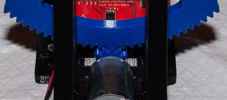
3 (2) Press the dowel pin into the back of the Sector Gear. Depending on the 3D printed part tolerances, it may be possible to press the pin into the part by hand. A tighter fit may require the use of a press, clamp, or pliers. (3) Press the ball bearing into the front of the Front Plate. Again, ease of installation and required equipment will depend on printed part tolerances. (4) Place the thrust bearing over the dowel pin on the back of the Sector Gear. (5) Press the dowel pin into the ball bearing until no gaps are present on either side of the thrust bearing. Due to the tight tolerances of these parts, this step requires a machine advantage. In this case, an arbor press was utilized. It is also possible to perform steps 2, 4, and 5 prior to performing step 3 in order to better protect the Front Plate.


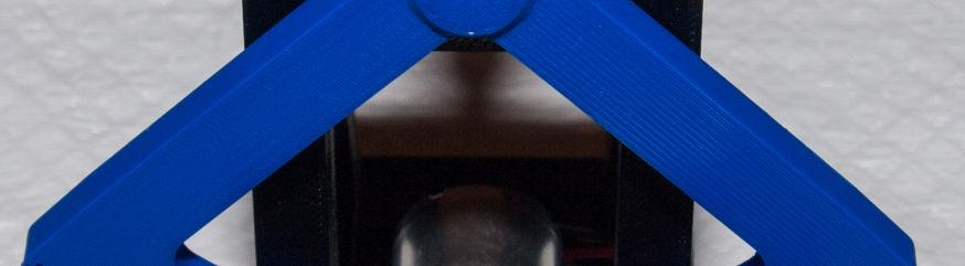
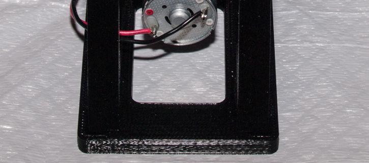
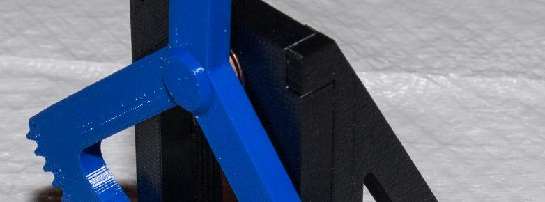
4 (6) Install the Drive Gear on the Mabuchi motor. Depending on the motor shaft and Drive Gear dimensions, it may be necessary to lightly press the parts together. If pressing is required, be careful not to damage the contacts or internal bearings of the motor. If pressing is not required, put a drop of super glue inside the Drive Gear shaft bore prior to installation, keep the motor shaft oriented downward to discourage glue from entering the motor, and make sure that the motor turns freely after 15 seconds. (7) Using two of the #4-40 x 3/8 button head screws, install the motor and Drive Gear assembly on the Front Plate. (8a) (8b) (8c) Glue a Side Plate to the Front Plate. Apply super glue to the mating surfaces of the Side Plate (a), fit the Side Plate and the Front Plate together, and use the Base Plate to align the assembly (b) press together for at least 15 seconds. Afterwards, remove the Base Plate (c). Repeat these steps for the second Side Plate. (9) Glue the Front and Side Plate assembly to the Base Plate. Apply super glue to the mating surfaces of the Side Plates and Front Plate, fit the assembly into the Base Plate, and press together for at least 15 seconds.


 Solder wires to the motor")


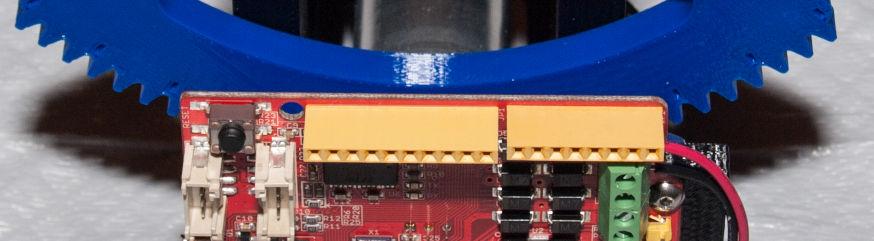
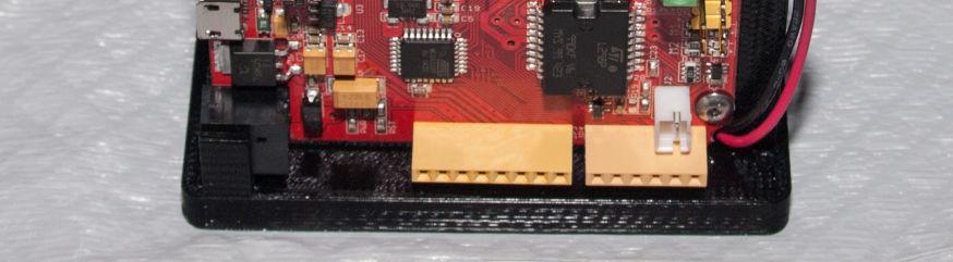
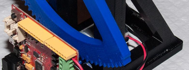
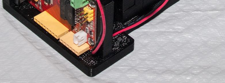
5 (10) Glue the magnet into the Drive Gear. Apply a drop of super glue to the magnet recess of the Drive Gear, place the magnet into the recess, and press together for at least 15 seconds. (11) Glue the Board Screw Support and the Board Inlet Support to the Base Plate by applying super glue to the mating surfaces. Place and press together for at least 15 seconds. (12) Solder the MR sensor to the back of the Hapkit board. Using two #4-40 x 3/8 button head screws and two #4 hex nuts, install the Hapkit board. (13) Solder wires to the motor contacts or attach two halves of an alligator clip cable as shown in the official instructions. Route the wires through the opening of the Side Plate and then through the gap between the Hapkit board and the Board Screw Support. Strip the ends of the wires and insert them into the top two terminal block openings. Use a flat head screwdriver to secure the terminals.


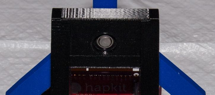

6 (14) Get ready to work with your completed Gear Drive Hapkit!
AFB (AIR FAN BEARING) INSTALLATION GUIDE
 INSTALLATION GUIDE") 654 AFB (AIR FAN BEARING) INSTALLATION GUIDE AFB PARTS Bearing Housing - Secured together with two 3/8 x 1.25 in. Cap Screws Black Wiper Seals - Secured together with O-ring cord (Subsequently depicted
654 AFB (AIR FAN BEARING) INSTALLATION GUIDE AFB PARTS Bearing Housing - Secured together with two 3/8 x 1.25 in. Cap Screws Black Wiper Seals - Secured together with O-ring cord (Subsequently depicted
AndyMark DART 12.
 AndyMark DART 12 Part Number Description QTY These Parts Are Pre-Assembled by AndyMark am-0031 Bearing, 3/16"ID (R3) 1 am-0209 Bearing, 3/8"ID 1614ZZ 2 am-1028 Screw, #10-32x3/8 Pan Head Philips 8 am-1121
CRP700 Benchtop Basic CNC Machine Assembly Instructions. Updated 10/24/2014 SHEET 1 of 24
 CRP700 Benchtop Basic CNC Machine Assembly Instructions Updated 0//0 SHEET of NOTE: This piece of extrusion is mounted wide side up Quick Tip: Lay extrusion on table as shown for easy assembly BASE ASSEMBLY:.
Tuf-Lite and Tuf-Lite II Fans 4000 Series Hub
 Tuf-Lite and Tuf-Lite II Fans 4000 Series Hub INSTALLATION MANUAL Hudson Tuf-Lite and Tuf-Lite II fan blades Adjustable Pitch Fan Assembly 15 thru 20 Diameter Hudson Tuf-Lite (black) fan blades are made
Metroboard Pulley Replacement Procedure
 Metroboard Pulley Replacement Procedure 1) Remove the two transmission cover screws (1/8 allen driver). Then remove the transmission cover. Note there is a split lock washer and flat washer as well, so
MS2 Straight Key Kit Assembly Manual
 American Morse Equipment MS2 Straight Key Kit Assembly Manual Thank you for purchasing our MS2 Miniature Straight Key Kit! Please take a few minutes to look over these instructions before starting assembly.
Tuf-Lite and Tuf-Lite II Fans 4000 Series Hub
 Tuf-Lite and Tuf-Lite II Fans 4000 Series Hub INSTALLATION MANUAL Hudson Tuf-Lite and Tuf-Lite II fan blades Adjustable Pitch Fan Assembly 15 thru 20 Diameter Hudson Tuf-Lite (black) fan blades are made
Tuf-Lite III Fans K Hi Temp 3000KHT Series Hub
 Tuf-Lite III Fans K Hi Temp 3000KHT Series Hub INSTALLATION MANUAL Adjustable Pitch Fan Assembly 11 thru 15 Diameter Hudson Tuf-Lite III fan blades Hudson Tuf-Lite III Hi Temp (Red) fan blades are of single
Tuf-Lite II Fans H Hi Temp 3000HT Series Hub
 Tuf-Lite II Fans H Hi Temp 3000HT Series Hub INSTALLATION MANUAL Hudson Tuf-Lite II Hi Temp Fan Blades Adjustable Pitch Fan Assembly 5 through 14 Diameter Hudson Tuf-Lite II Hi Temp fan blades (Red) are
Tuf-Lite III Fans 3000K Series Hub
 Tuf-Lite III Fans 3000K Series Hub INSTALLATION MANUAL Adjustable Pitch Fan Assembly 11 thru 15 Diameter Hudson Tuf-Lite III fan blades Hudson Tuf-Lite III fan blades are of single piece fiberglass reinforced
Tuf-Lite II Fans 3000H Series Hub
 Tuf-Lite II Fans 3000H Series Hub INSTALLATION MANUAL Adjustable Pitch Fan Assembly 5 through 14 Diameter Hudson Tuf-Lite II Fan Blades Hudson Tuf-Lite II (white, prev. Blue**) are made from fiberglass
Tuf-Lite II Fans 3000H Series Hub
 Tuf-Lite II Fans 3000H Series Hub INSTALLATION MANUAL Adjustable Pitch Fan Assembly 5 through 14 Diameter Hudson Tuf-Lite II Fan Blades Hudson Tuf-Lite II (white, prev. blue**) fan blades are made from
Tuf-Lite II Fans 3000HC Series Hub
 Tuf-Lite II Fans 3000HC Series Hub INSTALLATION MANUAL Hudson Tuf-Lite II fan blades Adjustable Pitch Fan Assembly 8 through 10 Diameter Hudson Tuf-Lite II (White) are made from fiberglass reinforced vinyl-ester
For additional assistance call
 The following pages will help guide you through the process of assembling your new 48 custom prize wheel. Choose an assembly area with plenty of room to lay your pieces on the floor and also a bench or
Replacement of Pitch Link Retainer and Service Improvement of the Pitch Control System. Effectivity: Helicopters manufactured prior to January, 1981
 Page 1 of 12 Date: December 2, 1981 Subject: Models: Replacement of Pitch Link Retainer and Service Improvement of the Pitch Control System F-28C and 280C Effectivity: Helicopters manufactured prior to
This manual will aid in the assembly of the FireBall V90 and FireBall X90. The assembly of both machines will be identical, unless specified.
 This manual will aid in the assembly of the FireBall V90 and FireBall X90. The assembly of both machines will be identical, unless specified. Step #1 Lay all parts out to verify quantities. (2) 2 x 25-1/4
Tuf-Lite III Fans 5000K Series Hub
 Tuf-Lite III Fans 5000K Series Hub INSTALLATION MANUAL Hudson Tuf-Lite III fan blades Adjustable Pitch Fan Assembly 20 thru 30 Diameter Hudson Tuf-Lite III fan blades are of single piece fiberglass reinforced
SERVICE PARTS LIST PAGE 1 OF 6 BASE ASSEMBLY SPECIFY CATALOG NO. AND SERIAL NO. WHEN ORDERING PARTS 12" SLIDING COMPOUND MITER SAW
 PAGE 1 OF 6 BASE ASSEMBLY 00 0 CATALOG NO. EXAMPLE: SPECIFY CATALOG NO. AND NO. WHEN ORDERING PARTS 6955-20 1 02-80-0050 Thrust Bearing (1) 2 05-80-0510 M5 x 12mm Flat Head T-20 Screw (5) 3 05-81-0135
Installing the Partridge RA Extension on Losmandy G11
 Installing the Partridge RA Extension on Losmandy G11 Michael Herman July 20, 2015 Tools: 3/16 inch hex key (allen wrench) [If desired for DEC indicator ring friction improvement: flat screwdriver, and
WSG 8-115; 8-125; P; WSG ; WSG P; WSG PS; WSG P; WSG 15-70Inox
 Repair instructions Page of 47 Contents. Models described 2. Technical data 3. Notes and requirements 4. Tools required 5. Lubricants and auxiliary substances required 6. Disassembly 7. Assembly 8. Connection
ELECTRIC TOOL CORPORATION
 Cat. No. -0 / Hex Demolition Hammer Cat. No. 0-0 Spline Rotary Hammer MILWAUKEE ELECTRIC TOOL CORPORATION W. LISBON ROAD BROOKFIELD, WISCONSIN 00-0 -9-00 d 000 -9-00 d SpecialTools Require Forcing discs
3850, Drum & Disc Brake Lathes. Parts Identification
 3850, 3860 Drum & Disc Brake Lathes Parts Identification READ these instructions before placing unit in service. KEEP these and other materials delivered with the unit in a binder near the machine for
Tuf-Lite III Fans 5000K Series Hub
 Tuf-Lite III Fans 5000K Series Hub INSTALLATION MANUAL Hudson Tuf-Lite III fan blades Adjustable Pitch Fan Assembly 20 thru 30 Diameter Hudson Tuf-Lite III fan blades are of single piece fiberglass reinforced
3000, 4000, 4100, 7500, 7700
 3000, 4000, 4100, 7500, 7700 Drum & Disc Brake Lathes s Identification READ these instructions before placing unit in service. KEEP these and other materials delivered with the unit in a binder near the
RYOBI 10 IN (254 MM) TABLE SAW MODEL NO. BT REPAIR SHEET
 TABLE SAW MODEL NO. BT REPAIR SHEET") RYOBI 0 IN (2 MM) TABLE SAW MODEL NO. BT00- REPAIR SHEET 2 RYOBI 0 in. (2 mm) TABLE SAW - MODEL NO. BT00- FOR MITER TABLE ASSEMBLY, REFER TO FIGURE B FOR BLADE GUARD ASSEMBLY, REFER TO FIGURE E FOR RIP
RYOBI 0 IN (2 MM) TABLE SAW MODEL NO. BT00- REPAIR SHEET 2 RYOBI 0 in. (2 mm) TABLE SAW - MODEL NO. BT00- FOR MITER TABLE ASSEMBLY, REFER TO FIGURE B FOR BLADE GUARD ASSEMBLY, REFER TO FIGURE E FOR RIP
Parts Catalog. S-Series Slicer Smart Manual SG13. Model:
 , 07 99507 ECN 065 Parts Catalog S-Series Slicer Smart Manual Model: SG SG 0/0/07 Rev. G IMPORTANT! TO EXPEDITE SHIPMENT OF PARTS, ALWAYS SPECIFY MODEL, REV, PART NUMBER, AND SERIAL NUMBER OF UNIT. GLOBE
M2 Assembly. M2 Sub-Assemblies mm Belt Sub-Assembly mm Belt Sub-Assembly Spider Sub-Assembly... 4
 M2 Assembly Table of Contents M2 Sub-Assemblies... 3 630mm Belt Sub-Assembly... 3 702mm Belt Sub-Assembly... 3 Spider Sub-Assembly... 4 Idler Bolt Sub-Assembly... 8 Y Motor Sub-Assembly... 9 X Motor Sub-Assembly...
CRP700 Benchtop Basic CNC Machine Assembly Instructions. Updated 9/11/2014 SHEET 1 of 25
 CRP700 Benchtop Basic CNC Machine Assembly Instructions Updated 9//0 SHEET of NOTE: This piece of extrusion is mounted wide side up Quick Tip: Lay extrusion on table as shown for easy assembly BASE ASSEMBLY:.
SERVICE PARTS LIST. M18 FUEL SAWZALL Reciprocating Saw F56A BULLETIN NO CATALOG NO
 47(5x) 46 45 00 44 0 59 43 42 84 51 57 46 47 48 59 83 64 77 48 47(2x) 49(2x) 40 58 See service note on page 5 41 82 51 40 41 42 43 44 45 87 52 27 28 34 57 29 (6x) 60 28 EXAMPLE: Component Parts (Small
EEBR312A Brake Lathes Parts Identification
 EEBR312A Brake Lathes s Identification READ these instructions before placing unit in service. KEEP these and other materials delivered with the unit in a binder near the machine for ease of reference
SERVICE PARTS LIST PAGE 1 OF 6 BASE ASSEMBLY SPECIFY CATALOG NO. AND SERIAL NO. WHEN ORDERING PARTS 12" DUAL BEVEL COMPOUND MITER SAW B27B
 PAGE 1 OF 6 BASE ASSEMBLY 00 0 EXAMPLE: Component Parts (Small #) Are Included When Ordering The Assembly (Large #). SPECIFY CATALOG NO. AND NO. WHEN ORDERING PARTS = Part number change from previous service
ABM International, Inc.
 ABM International, Inc. Lightning Stitch required 1 1.0: Parts List head and motor assembly (Qty. 1) Reel stand (Qty. 1) Needle bar frame clamp (Qty. 1) Motor drive (Qty. 1) 2 Cable harness with bracket
Wheeler Rex Ashtabula, Ohio Tel: Fax:
 Wheeler Rex Ashtabula, Ohio Tel: 800 321 7950 Fax: 440 992 2925 wheeler@wheelerrex.com www.wheelerrex.com December 2012 There are three different types of shell cutters. Nominal Hole Size Part No. 4" 3395
RYOBI 10 in. (254 mm) TABLE SAW MODEL NO. BT3100 REPAIR SHEET
 TABLE SAW MODEL NO. BT3100 REPAIR SHEET") RYOBI 0 in. (4 mm) TABLE SAW MODEL NO. BT00 REPAIR SHEET FOR MITER TABLE ASSEMBLY, REFER TO FIGURE B FOR BLADE GUARD ASSEMBLY, REFER TO FIGURE E FOR RIP FENCE ASSEMBLY, REFER TO FIGURE C FOR MOTOR ASSEMBLY,
RYOBI 0 in. (4 mm) TABLE SAW MODEL NO. BT00 REPAIR SHEET FOR MITER TABLE ASSEMBLY, REFER TO FIGURE B FOR BLADE GUARD ASSEMBLY, REFER TO FIGURE E FOR RIP FENCE ASSEMBLY, REFER TO FIGURE C FOR MOTOR ASSEMBLY,
RYOBI 10 in. TABLE SAW - MODEL NO. BT3000
 FOR MITER TABLE ASSEMBLY, REFER TO FIGURE 0 RYOBI 0 in. TABLE SAW - MODEL NO. BT000 FIGURE 5: 0 in. TABLE SAW FOR BLADE GUARD ASSEMBLY, REFER TO FIGURE FOR RIP FENCE ASSEMBLY, REFER TO FIGURE FOR MOTOR
400GTO Lubrication Guide
 400GTO Lubrication Guide Lubrication Guidelines for the following equatorial mounting: 400GTO Servo with GTOCP2 or CP3 Controller For other 400 models please review other postings as they become available.
GlideRite Retractable Cover System For Hot Spot Spas (SE & SLX only)
") List of Contents Quantity Description 12 #10 x 1 ½ Flat Head Phillips Screw (see pg. 2) 2 #10 x ½ Pan Head Phillips Screw (see pg. 2) 8 ¼ x 2 ½ Lag Bolt (see pg. 2) 7 ¼ 20 x 5 / 8 Hex Head Bolt (see pg.
List of Contents Quantity Description 12 #10 x 1 ½ Flat Head Phillips Screw (see pg. 2) 2 #10 x ½ Pan Head Phillips Screw (see pg. 2) 8 ¼ x 2 ½ Lag Bolt (see pg. 2) 7 ¼ 20 x 5 / 8 Hex Head Bolt (see pg.
MOTOR & BULK HEAD. A Manual for Repair and Maintenance Technicians
 MOTOR & BULK HEAD A Manual for Repair and Maintenance Technicians CAUTION This manual is designed to help technicians who are already experienced in workshop procedures and know how to handle tools. Only
Parts Catalog. S-Series Slicer Manual Frozen Option S13. Model:
 , 07 995 ECN 08 Parts Catalog S S-Series Slicer Manual Frozen Option Model: S 05/0/07 Rev. G IMPORTANT! TO EXPEDITE SHIPMENT OF PARTS, ALWAYS SPECIFY MODEL, REV, PART NUMBER, AND SERIAL NUMBER OF UNIT.
7141 & NATIONAL POLE VAULT STANDARDS SPECIFICATIONS
 SPECIFICATIONS Specifications: This standard has a clamping system and a handle added for ease of operation. The clamping system is above the base pad protectors when in the lowest position and the tightening
Avant Mostro 700 Nitro
 Assembly Manual Version 1.10 Mostro unleash the monster inside Latest Assembly Manual is located at: http://www.avantrc.com/products/mostro/n700mostromanual.pdf Copyright 2014 Avant RC. All rights reserved
RIPPER PEDAL. Bearing / Axle Replacement. ( Disassembly )
") RIPPER PEDAL Bearing / Axle Replacement ( Disassembly ) 1 1. Use good quality tools to avoid stripping screw sockets. 2. When servicing your pedals, work on one side at a time to prevent parts from mixing
RIPPER PEDAL Bearing / Axle Replacement ( Disassembly ) 1 1. Use good quality tools to avoid stripping screw sockets. 2. When servicing your pedals, work on one side at a time to prevent parts from mixing
WORK SURFACE I highly recommend getting an Olfa knife. It is difficult to cut 1/2 foamcore with just an Exacto. RAZOR KNIFE CUTTING MAT WIRE CUTTERS
 RAZOR KNIFE CUTTING MAT WIRE CUTTERS MARKING TOOLS PLIERS CIRCLE STENCIL SMALL WOOD SAW COMPASS 12 METAL RULER* > 16 RULER HOT GLUE GUN RIGHT TRIANGLE SCREWDRIVER Find a sturdy table that is in a well-lit
RP4 INSTRUCTION MANUAL
 RP4 INSTRUCTION MANUAL BEFORE YOU BEGIN Thank you for purchasing the Pemberton Raceworks and RP4 Designs RP4 pan car. This manual is intended people familiar with 1/10th scale pan car racing, and should
The Astronomical League
 The Astronomical League www.astroleague.org Library Telescope Modifications Check the collimation with the eyepiece cap provided (the one with the hole in its center) before starting on any modifications.
Part 7 Assembling the X axis
 Part 7 Assembling the X axis 1 2 The X axis is a key part of the printer, it carries the extruder on a carriage that moves the extruder laterally in the X axis. The x axis itself is moved vertically on
GlideRite Retractable Cover System For HotSpring & Tiger River Spas (except Classic & pre-2000 Landmark Spas)
") List of Contents Quantity Description 12 #10 x 1 ½ Flat Head Phillips Screw (see pg. 2) 2 #10 x ½ Pan Head Phillips Screw (see pg. 2) 8 ¼ x 2 ½ Lag Bolt (see pg. 2) 7 ¼ 20 x 5 / 8 Hex Head Bolt (see pg.
List of Contents Quantity Description 12 #10 x 1 ½ Flat Head Phillips Screw (see pg. 2) 2 #10 x ½ Pan Head Phillips Screw (see pg. 2) 8 ¼ x 2 ½ Lag Bolt (see pg. 2) 7 ¼ 20 x 5 / 8 Hex Head Bolt (see pg.
TIRE RACK INSTALLATION INSTRUCTIONS Dodge Sprinter
 Aluminess Products Inc 9402 Wheatlands Ct. #A Santee, CA 92071 619-449-9930 TIRE RACK INSTALLATION INSTRUCTIONS 07-11 Dodge Sprinter Please read before beginning Stainless steel hardware may bind together
HD38, HD58, HD78 REV
 HD38, HD58, HD78 REV. 07.29.2014 COVER for HD38, HD58, HD78 5 P004868 1/4-20x3/4 Button Head Cap Screw Stainless Steel 2 6 P001450 Lockwasher - Internal Tooth.250 6 8 P005200 Wave Disc Washer 4 10 P004869
PARTS LIST. Model MFT-HD Cleco
 PARTS LIST Model MFT-HD Cleco 0 0 0 0 0 0 0 0 HD-0- Centershaft HD-0- Centershaft Screw HD-0- Lift Collar HD-0- Eyebolt HD-0- Hex Nut HD-0- Draw Rod HD-0- Washer - Draw Rod HD-0- Face Plate, " Diameter
SERIES I MILLING MACHINES
 INSTALLATION, OPERATION, MAINTENANCE, AND PARTS LIST SERIES I MILLING MACHINES TP5260 Revised: August 29, 2005 Manual No. M-450 Litho in U.S.A. Part No. M -0009500-0450 June, 2003 MAINTENANCE PROCEDURES
Installation Instructions
 Installation Instructions XLC Generation 2 Self-aligning split bearing Experience In Motion 1 Equipment Check 1.1 Follow plant safety regulations prior to equipment disassembly: Lock out motor. Wear designated
ABM International, Inc. Navigator Assembly Manual
 ABM International, Inc. 1 1.0: Parts List Tablet (Qty. 1) Tablet mount (Qty. 1) NOTE: Mount may appear and operate different then image below Control Box (Qty. 1) Motor Power Supply (Qty. 1) 2 X-axis motor
Page 1. SureMotion Quick-Start Guide: LARSACC_QS 1st Edition - Revision A 03/15/16. Standard Steel Bolt/Screw Torque Specifications
 R K C T I Repair Kit Product Compatibility Repair Kit # Linear Actuator Assembly # LARSACC-013 LARSACC-014 LARSD2-08T12BP2C (12-in travel) LARSD2-08T24BP2C (24-in travel) C P I R K 1 ea Ball Screw with
REPAIR INSTRUCTIONS. Cat. No Cat. No MILWAUKEE ELECTRIC TOOL CORPORATION. SDS Max Demolition Hammer. SDS Max Rotary Hammer
 Cat. No. 9-0 SDS Max Demolition Hammer Cat. No. -0 SDS Max Rotary Hammer MILWAUKEE ELECTRIC TOOL CORPORATION W. LISBON ROAD BROOKFIELD, WISCONSIN 00-0 8-9-0 d 000 8-9-0 d Special Tools Require Forcing
Brake Gears Suspension Body - TCS
 Brake Gears Suspension Body - TCS-980 Brake Gears Suspension Body - TCS-980 100 426230A00 CENTRE HOUSING 1 101 426230A50 LOAD SHEAVE 1 102 426230200 COUPLING 1 103 426230350 CHAIN GUIDE 1 104 426230360
Operating Instructions For Lockformer Button Punch Flanger
 Capacity: 20 to 28 Gauge Galvanize Operating Instructions For Lockformer Button Punch Flanger To satisfactorily form the 90º button punch flange on light gauge materials, it was necessary to form the metal
CNC Router Parts PRO Machine Kit Cable Track Installation Instructions
 1 1 X CABLE TRACK TRAYS & BRACKETS The cable track on the side of the system is supported by a metal tray (or multiple trays for longer systems such as a PRO4896). These trays hang from brackets on the
Parts Catalog. S-Series Slicer Smart Manual SG13. Model:
 , 08 99507 ECN 065 Parts Catalog S-Series Slicer Smart Manual Model: SG SG /6/08 Rev. R IMPORTANT! TO EXPEDITE SHIPMENT OF PARTS, ALWAYS SPECIFY MODEL, REV, PART NUMBER, AND SERIAL NUMBER OF UNIT. GLOBE
HDL(M)6 Nut/Screw Assembly
6 Nut/Screw Assembly") HDL(M)6 Nut/Screw Assembly Remove, repair, and reassemble the nut and screw assembly in your HDL series double lock vise. In these instructions when we refer to the front of the vise or nut/screw assembly,
HDL(M)6 Nut/Screw Assembly Remove, repair, and reassemble the nut and screw assembly in your HDL series double lock vise. In these instructions when we refer to the front of the vise or nut/screw assembly,
Model MFC-2 Split Frame Clamshell Operation and Parts Manual
 Model MFC- Split Frame Clamshell Operation and Parts Manual Corporate H&S Tool, Inc. Mail: P.O. box Wadsworth, OH Shipping: Weber Dr. Wadsworth, OH U.S.A. Tel: +-0--0 Fax: +-0-- www.hstool.com e-mail:
MODEL NO.: MI / 42100
 MODEL NO.: MI-50 / 00 MODEL NO.: MI-50 BOX 1 OF 6 ROUTER LIFT PARTS BREAKDOWN Router Lift Assembly 6 5 2 2 1 5 5 8 12 11 2 26 27 0 12 26 27 27 22 22 27 19 A 5 26 12 26 22 25 25 7 18 18 15 15 7 9 1 17 2
Chain Drive Vise. Installation Instructions. (revised 05/04/2016)
") Chain Drive Vise Installation Instructions (revised 05/04/2016) Lie-Nielsen Chain Drive Vise Instructions Table of Contents page About Your Chain Drive Vise 3 Parts List 4 Exploded Parts Diagram 5 step
Chain Drive Vise Installation Instructions (revised 05/04/2016) Lie-Nielsen Chain Drive Vise Instructions Table of Contents page About Your Chain Drive Vise 3 Parts List 4 Exploded Parts Diagram 5 step
CNC Router Parts. Standard Rack & Pinion Drive Assembly Instructions
 CNC Router Parts Standard Rack & Pinion Drive Tools List The following tools will be used for assembly and installation of the Standard Rack & Pinion Drive: Imperial Allen Wrench Set - 3/32", 5/32", 3/16",
Shay Drive Shafts & Universal Fabrication
 Shay Drive Shafts & Universal Fabrication Nelson Riedel Nelson@NelsonsLocomotive.com Initial: 5/22/03 Last Revised: 06/06/2004 The following describes how I machined the universal rings and drive shafts.
MOTORIZED STANDARD SHADE WITH CABLES Installation Instructions
 Tools Needed Drill Measuring Tape Pencil 2 Level Plumb Line ¼ Masonry Drill Bit Hammer Linesmans Pliers Cable Cutters Phillips & Flat-Head Screw Driver 11/32 Socket or Open End Wrench 5/32 Allen Wrench
Section A Gear Box September A
 Section A Gear Box September 06 1A Index 1. 1-10016-000 Gear Box Oil Pan. 1-100486-000 Clutch Lever Assembly, See Page 9A for breakdown. 1-1004-000 Clutch Cam, for all A machines prior to Serial #5 1-104-000
Motorized or Crank Operated Fortress Zipper Track Shade with Housing and Side Track Installation Instructions
 Motorized or Crank Operated Fortress Zipper Track Shade with Housing and Side Track Installation Instructions Tools Needed Drill 3/8 Metal Drill Bit ¼ Masonry Drill Bit Measuring Tape Pencil 4 Level Phillips
SECTION 10: PARTS. Main Model G0771Z (Mfd. Since 09/16)
") SECTION 10: PARTS Main 96 103 105 119 104 120 102 101 124 29-1 29-4 29-2 29-5 29-3 29-6 29-7 29-8 29-9 29-10 97 98 99 121 100 106 97 98 99 100 121 96 29 27 28 125 24 25 26 30 53 41 40 39 31 34 114 115
SECTION 10: PARTS Main 96 103 105 119 104 120 102 101 124 29-1 29-4 29-2 29-5 29-3 29-6 29-7 29-8 29-9 29-10 97 98 99 121 100 106 97 98 99 100 121 96 29 27 28 125 24 25 26 30 53 41 40 39 31 34 114 115
Name Standard or Description QTY.
 Part List Part Number Name Standard or Description QTY. 1 Base - 1 2 Nut Hexagon Nut ISO - 4032 - M3 19 3 Motor/Encoder Assembly Mabuchi RS-645VA and Encoder 1 1 4 M3x10 Screw ISO 7045 - M3 x 10 2 5 Steel
BBF Series Blower Base Frame Assembly Instructions Rev.: BFA-9105
 BBF Series Blower Base Frame Assembly Instructions Rev.: BFA-9105 These assembly instructions are to be used as a general reference guide to facilitate assembly. Please consult the blower, bushing, sheave,
3000, 4000, 4100, 7500, 7700
 3000, 4000, 4100, 7500, 7700 Drum & Disc Brake Lathes Model 4000 Shown s Identification READ these instructions before placing unit in service. KEEP these and other materials delivered with the unit in
MODELS 49 RA 49 RAZ 49 RAC
 General Safety and Maintenance Manual MODEL grinder featuring a rear exhaust. Model Number Exhaust Direction REAR Throttle Type (L) Lever or (K) Safety Lever Speed 12000 to 14000 R.P.M (13500rpm is standard)
Assembly Instructions Nevins Phone Booth
 Assembly Instructions Nevins Phone Booth Included Hardware Tools Required supplied by installer Drill & Bit Bolt A - (16) 1/4-20 x 1-1/2 hex head Bolt B - (20) 1/4-20 x 2-1/2 phillips head Screw 1 - (24)
ELECTRIC TOOL PARTS LIST
 Hitachi Power Tools LIST E936 ELECTRIC TOOL PARTS LIST COMPOUND SAW Model 2004 4 20 (E1) 1 2 3 23 24 7 8 9 10 6 5 4 15 11 16 12 13 12 14 18 25 26 27 28 29 30 19 17 1 9 11 16 21 624 20 22 39 40 41 42 35
TeacherGeek Sumo Bot Vehicle Application Guide
 SUMO BOT VEHICLE EXAMPLE BUILD TeacherGeek Sumo Bot Vehicle Application Guide TeacherGeek, 011 SUMO BOT VEHICLE EXAMPLE BUILD TeacherGeek TeacherGeek s Sumo Bot Vehicle Activity is the perfect way to encourage
Strata. urniture. Adriana Instructions. Parts in the Arm Box: Parts in the Body Box: Watch our assembly videos at
 1A Watch our assembly videos at www.strataf.com/videos Parts in the Arm Box: Arm - Outside View Arm - Inside View 1B Parts in the Body Box: Back Deck x 1 Seat Deck x 1 with the Feet attached Back Panel
Tin Lizzie 18 Assembly Instructions
 Tin Lizzie 18 Assembly Instructions Revision: 07/29/16 Table of Contents Aides 3 Before You Begin 5 Aides 5 Tools 6 Perfect Stitch Parts 2 12 Modify the Machine 12 Prepare Drill Templates 12 Front Display
SR-1.0 Manual, a.doc 11/14/2006 Page 1 of 17
 SR-1.0 Manual, 20061108a.doc 11/14/2006 Page 1 of 17 ASSEMBLY INSTRUCTIONS, MODEL SR-1.0 EXTRUSION HEAD STREAMLINE EXTRUSION, INC. Following is a set of photos and verbal descriptions for assembling the
Astro-Physics Inc. 400QMD Lubrication/Maintenance Guide
 Astro-Physics Inc. 400QMD Lubrication/Maintenance Guide The following guidelines should be followed to lubricate the three main parts of the 400QMD mount. The QMD stands for Quartz Micro-Drive controller.
RYOBI. 10 in. (254 mm) TABLE SAW MODEL NO. BTS15 REPAIR SHEET
 TABLE SAW MODEL NO. BTS15 REPAIR SHEET") RYOBI 0 in. ( mm) TABLE SAW MODEL NO. BTS REPAIR SHEET FIGURE A 0 0 0 0 The model number will be found on a plate attached to the motor housing. Always mention the model number in all correspondence regarding
RYOBI 0 in. ( mm) TABLE SAW MODEL NO. BTS REPAIR SHEET FIGURE A 0 0 0 0 The model number will be found on a plate attached to the motor housing. Always mention the model number in all correspondence regarding
Model W1837 (For Machines Mfd. Since 8/18) PARTS. Main PARTS -83-
 PARTS. Main PARTS -83-") -83- Main 29 30 31 34 35 36 37 38 39 40 41 42 43 44 45 46 47 48 49 50 51 52 53 54 55 56 57 58 61 62 63 64 65 66 67 68 69 70 71 72 73 74 75 113 96 90 91 92 93 95 96 97 98 100 101 102 103 104 105 106 109
-83- Main 29 30 31 34 35 36 37 38 39 40 41 42 43 44 45 46 47 48 49 50 51 52 53 54 55 56 57 58 61 62 63 64 65 66 67 68 69 70 71 72 73 74 75 113 96 90 91 92 93 95 96 97 98 100 101 102 103 104 105 106 109
Exploded View Saw Base - Model 7060 Semi-Automatic Cut-Off Band Saw
 Exploded View Saw Base - Model 7060 Semi-Automatic Cut-Off Band Saw 136 137 135 134 132 131 133 113 114 115 117 116 118 119 120 121 79 78 77 107 108 65 76 110 109 66 10 9 6 11 5 4 8 7 75 74 73 72 111 112
Hydraulic Clamp Carrier. Installation & Operation Manual
 Hydraulic Clamp Carrier Installation & Operation Manual Hydraulic Clamp Carrier Installation & Operation Manual Quick Machinery Company 8272 Peninsula Drive Kelseyville, CA 95451 phone: (707) 272-6719
Chain Drive Vise. Installation Instructions. (revised 11/29/2018)
") Chain Drive Vise Installation Instructions (revised 11/29/2018) Lie-Nielsen Chain Drive Vise Instructions Table of Contents page About Your Chain Drive Vise 3 Parts List 4 Exploded Parts Diagram 5 step
Chain Drive Vise Installation Instructions (revised 11/29/2018) Lie-Nielsen Chain Drive Vise Instructions Table of Contents page About Your Chain Drive Vise 3 Parts List 4 Exploded Parts Diagram 5 step
12. Wings, Flaps, Ailerons and Struts
 12. Wings, Flaps, Ailerons and Struts Fit Aileron Hinges Reference: Drawing 20270K2 Photo 12.1 Parts Required: 2007092 Aileron LS 200809N Aileron RS 2001394 Hinge 3/16 A1 (4) 2001694 Hinge Pin (4) PH0059N
RZR 4 Doors Part # Polaris RZR XP & Turbo ( ) Black
 Black") Racing 3191 N Washington St. Suite 2 Chandler, AZ 85225 1 (800) 708-9803 http://www.racing.com RZR 4 Doors Part # 07-1802 Polaris RZR XP 4 1000 & Turbo (2015-2018) Black Revision No: 01 Revision Date:
Racing 3191 N Washington St. Suite 2 Chandler, AZ 85225 1 (800) 708-9803 http://www.racing.com RZR 4 Doors Part # 07-1802 Polaris RZR XP 4 1000 & Turbo (2015-2018) Black Revision No: 01 Revision Date:
SAFETY INSTRUCTIONS. Wear protective clothing, including safety glasses and steel toe boots.
 SAFETY INSTRUCTIONS Wear protective clothing, including safety glasses and steel toe boots. DO NOT allow loose clothing or long hair near machine operations. Keep work site and machine clean. Use brush
Guide Pulley System [GPS]
![Guide Pulley System [GPS]](/thumbs/86/93494578.jpg "Guide Pulley System [GPS]") Guide Pulley System [GPS] The purpose of the guide pulley system is to guide the wire from the dancer pulley system to the guide rollers. Two of these systems exist: on both sides of the machine. The pulley
Guide Pulley System [GPS] The purpose of the guide pulley system is to guide the wire from the dancer pulley system to the guide rollers. Two of these systems exist: on both sides of the machine. The pulley
By C.W. Woodson From the pages of Model Craftsman magazine June, 1937
 By C.W. Woodson From the pages of Model Craftsman magazine June, 1937 As shown in Fig. 1, the tool post grinder for which plans are given here can be used to finish up delicate work to more accurate dimensions
Maintenance Information
 47104302 Edition 1 November 2012 Cordless Drill/Driver QX Series Maintenance Information Save These Instructions Tool Diagnosis 1. Before servicing this unit, you will need a fully charged battery of known
SPARE PARTS LIST MODEL NO PAGE 1 ITEM PART NO. DESCRIPTION QTY NOTE
 PAGE 1 001 342186-7 SWITCH PROTECTOR 1 002 911118-1 PAN HEAD SCREW M4X12 6 003 155512-9 SWITCH PLATE 1 004 651757-2 SWITCH ABK266 1 006 685712-2 SPONGE SHEET 60X60 1 007 911118-1 PAN HEAD SCREW M4X12 1
OPERATIONAL MANUAL V1.0. Removing/Replacing Blades
 OPERATIONAL MANUAL V1.0 BLUEROCK WS-212 Wire Stripper Removing/Replacing Blades CAUTION!! IMPORTANT!! DANGER!! WARNING!! DISCONNECT MACHINE FROM POWER BEFORE PROCEEDING!! Estimated Completion Time: 90
Legacy Woodworking Machinery a division of Phantom Engineering. The Legacy CNC. Assembly Manual
 Legacy Woodworking Machinery a division of Phantom Engineering The Legacy CNC Assembly Manual New Orientation of the Legacy Step one: Re-orientation of the machine Remove the X-axis screw and supports.
FMT 250; FMT 250Q; FMT 250QSL. Repair instructions FMT 250Q / FMT 250QSL. Page 1 of 30
 Repair instructions FMT 250 FMT 250Q / FMT 250QSL Page 1 of 30 Contents 1. Models described 2. Technical data 3. Notes and requirements 4. Tools required 5. Lubricants and auxiliary substances required
DRIVE COMPONENTS REMOVAL. 9. FXCW/C: see Figure Remove bolt (9), sprocket retainer (8), and thrust washer (7). NOTE PRIMARY DRIVE LOCKING TOOL
, sprocket retainer (8), and thrust washer (7). NOTE PRIMARY DRIVE LOCKING TOOL") DRIVE COMPONENTS REMOVAL PART NUMBER HD-7977 TOOL NAME PRIMARY DRIVE LOCKING TOOL S To remove the primary chain, remove compensating sprocket, clutch assembly and primary chain as an assembly:. Remove
DRIVE COMPONENTS REMOVAL PART NUMBER HD-7977 TOOL NAME PRIMARY DRIVE LOCKING TOOL S To remove the primary chain, remove compensating sprocket, clutch assembly and primary chain as an assembly:. Remove
3000, 4000, 4100, 7500, 7700 Drum & Disc Brake Lathes
 3000, 4000, 4100, 7500, 7700 Drum & Disc Brake Lathes Model 4000 Shown Parts Identification READ these instructions before placing unit in service. KEEP these and other materials delivered with the unit
Hubble GOTO Installation Instruction (1.3, 04/30/2014)
") Hubble GOTO Installation Instruction (1.3, 04/30/2014) 1. Preparation... 1 1.1 Tools required... 1 1.2 AZ GOTO Drive Parts List...1 1.3 ALT GOTO Drive Parts List... 1 2. The Azimuth motor drive installation...2
Hubble GOTO Installation Instruction (1.3, 04/30/2014) 1. Preparation... 1 1.1 Tools required... 1 1.2 AZ GOTO Drive Parts List...1 1.3 ALT GOTO Drive Parts List... 1 2. The Azimuth motor drive installation...2
Fig Remove chain cover plate bolts. Fig Remove hammer member. Fig Loosen set screws at base of 12-tooth sprocket.
 Fig. 17.2. Remove chain cover plate bolts. Fig. 17.1. Remove hammer member. Fig. 17.3. Remove chain cover plate. Fig. 17.4. Loosen set screws at base of 12-tooth sprocket. Page 61 Fig. 17.5. Remove socket
RMD3000 DPO3000 Series Rackmount Kit
 Instructions RMD3000 DPO3000 Series Rackmount Kit 071-2424-00 Warning The servicing instructions are for use by qualified personnel only. To avoid personal injury, do not perform any servicing unless you