b) It is assumed a suitably qualified electrical installer will make all electrical connections.
|
|
|
- Owen Spencer
- 5 years ago
- Views:
Transcription
1 Installation Instructions for the Multi SmartBox Please read thoroughly before beginning the installation. Notes a) Proficient DIY skills are assumed. b) It is assumed a suitably qualified electrical installer will make all electrical connections. c) The Multi SmartBox is designed for anchoring to a floor. A level and firm floor, such as concrete or flags, is assumed. It is recommended that the Multi unit is additionally anchored to a solid wall for extra secure reinforcement. d) Please consult with your local hardware store in the event your property requires alternative fixing parts to those supplied with your Multi SmartBox. Note that the supplier or manufacturer of your Multi SmartBox will not be responsible for any damages carried out by this installation. e) Anchor Holes have not been drilled in the Multi SmartBox so as to allow the purchaser flexibility in how to do the installation. Tools required Power Screw Driver recommended 8mm Metal Drill Metal 8mm Masonry Drill Bit Extended 8mm Drill Bit sufficiently long to drill through the property wall Adjustable Spanner Marking pencil Parts supplied 4 Adjustable feet 2 Floor Anchor Bolts, 8mm diameter, 120mm long 4 Wall Anchor Bolts, 8mm diameter, 80mm long Antenna +12V Power Charger Unit
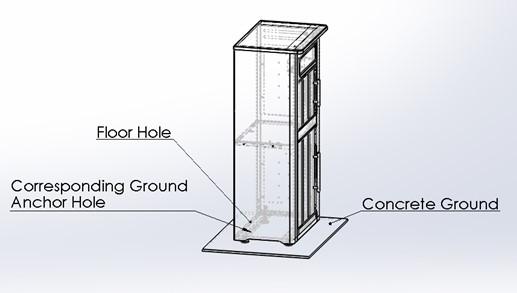
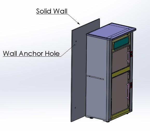
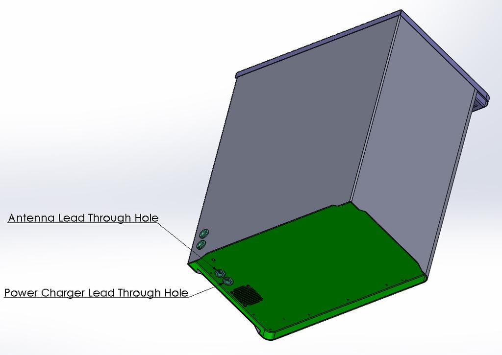
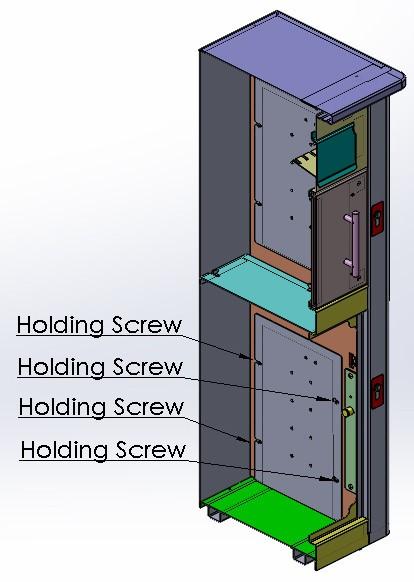
2 1. Preparation for Floor Installation Turn the Multi SmartBox on its side and drill 2 holes in its base (8mm Metal Drill Bit) to coincide with the 2 predrilled floor holes in the support bars. Figure 1. Position the unit at its desired location. Ensure easy access is allowed for and that fully open doors do not impact on the location surrounds. Adjust the feet to ensure the unit is level. Mark through the 2 drilled floor holes to corresponding anchor hole positions on the concrete floor. Figure 2. Remove the unit and drill the 2 ground anchor holes in the concrete ground using the 8mm Masonry Drill bit to a depth of 100mm. 2. Preparation for Wall Installation Mark the positions for 4 holes in the unit s back and drill out using the 8mm Metal Drill Bit. Figure 3. Reposition the unit and insert the 2 floor anchor bolts. Ensure it is level and partially tighten the floor bolts. Mark through the 4 wall mount holes to corresponding positions in the solid wall. Remove the unit and drill out the wall holes using the 8mm Masonry Drill Bit to a depth of 80mm. 3. Antenna Connection and +12V Power Charger Connection For the purposes of these instructions, it is assumed that the Power Charger will be plugged into an electrical socket located within a property and that its lead be thread through an exterior wall to the SmartBox. Other arrangements could apply. For example, a +12V connection could be taken from an electric gate power supply, etc. Locate the Antenna and Power Charger Lead Holes at the back of the SmartBox. (Alternatively, locate the Lead Holes underneath the SmartBox). Figures 4a, 4b. Remove the SmartBox Internal Panel by undoing the 4 holding screws. Figure 5. A Control Module is attached on the inner side of the Internal Panel. This Control Module has mating connectors for the Antenna and Power Charger Leads. Antenna
3 Locate the Antenna connector on the Control Module. Thread the Antenna lead through the SmartBox Lead Hole and connect it to the Control Module's Antenna connector. The Antenna has a magnetic base. Attach the Antenna to a suitable position on the SmartBox. Power Charger Reposition the SmartBox and mark through the Charger lead hole to a corresponding hole on the solid wall. Remove the SmartBox and drill out the wall hole using the extended 8mm Masonry Drill Bit. Thread the Power Charger lead through the wall. Ensure the Power Charger is not plugged in. Reposition the SmartBox. Thread the Charger lead through the SmartBox Lead Hole and connect it to the Control Module's Charger connector. Replace the Internal Panel and reconnect the 4 holding screws. 4. Installation It is assumed that the Antenna and Power Charger Leads are connected. See 3 above. Reposition the Multi SmartBox. Insert the 2 floor 120mm anchor bolts for positioning. Partially screw in. Insert the 4 wall 80mm anchor bolts. Partially screw in. Gradually tighten all bolts until all are securely fixed to their anchor points.

4 Figure 1 Figure 2 Figure 3

5 Figure 4a Figure 4b Figure 5
Independent Containment System (ICS)
") Installing the Independent Containment System (ICS) Complete these instructions to install the Independent Containment System (ICS). Prerequisites This installation requires a team of at least two people.
Installing the Independent Containment System (ICS) Complete these instructions to install the Independent Containment System (ICS). Prerequisites This installation requires a team of at least two people.
ASSEMBLY INSTRUCTIONS DIY WALL BED KIT QUEEN BI FOLD DOOR CABINET & MECHANISM. Tools Required For Assembly. 6.5mm Masonry Drill Bit
 ASSEMBLY INSTRUCTIONS DIY WALL BED KIT QUEEN BI FOLD DOOR CABINET & MECHANISM Tools Required For Assembly No 2 & No 4 Phillips Head Screwdrivers No 2 Slot Head Screwdriver Hammer Electric Drill (Hammer
ULTRA SPACE SAVER SQUARED Installation Instructions
 Installation Instructions The Ultra Space Saver Squared has several steps for installation. Note that the single and double sided setups and parts are different. Make sure you follow the instructions according
Mount to the Wall INSTALLATION MANUAL
 Mount to the Wall 15 Locate the Wooden Studs This step applies to wooden stud wall installation only. Determine and mark the exact locations of two stud centers on the wall. Wooden studs should be spaced
Installation Instruction
 Tools Needed for Assembly Stud finder (for wood stud wall) Pencil Mark Electric drill Wood Stud Wall Installation Step 1. Locate the Wood Studs Installation Instruction Drill bit (for wood stud wall) Masonry
ULTRA SPACE SAVER Installation Instructions
 Installation Instructions The Ultra Space Saver has several steps for installation. Note that the single and double sided setups and parts are different. Make sure you follow the instructions according
INSTALLATION MANUAL SFM3
 INSTALLATION MANUAL SFM3 Sony Electronics, Inc. 16540 West Bernardo Drive San Diego, CA 92127 www.sony.com IN-SFM3.R0 Table of Contents WARNING STATEMENTS...- 3 - PARTS LIST...- 4 - INSTALLATION TOOLS...-
Allow 60 from door face
 Setbacks Allow 60 from door face TOOLS NEEDED Tape Measure Marker or Pencil Masonry Drill Bit 3/8 Hammer Drill Hammer Socket Wrenches and Wrench: 9/16, 1/2, 7/16, 1/4 drive socket wrench and 1/2 socket
Assembly Instructions Nevins Phone Booth
 Assembly Instructions Nevins Phone Booth Included Hardware Tools Required supplied by installer Drill & Bit Bolt A - (16) 1/4-20 x 1-1/2 hex head Bolt B - (20) 1/4-20 x 2-1/2 phillips head Screw 1 - (24)
WALL MOUNT LOCKER ASSEMBLY. 208 Chestnut St, Reading, PA (610)
") WALL MOUNT LOCKER ASSEMBLY 208 Chestnut St, Reading, PA 19602 (610)376-2666 Locker Assembly Wall Mount: locker Installation Introduction: Before beginning, check to ensure the floor is level, and the wall
WALL MOUNT LOCKER ASSEMBLY 208 Chestnut St, Reading, PA 19602 (610)376-2666 Locker Assembly Wall Mount: locker Installation Introduction: Before beginning, check to ensure the floor is level, and the wall
CONTENTS TOOL LIST U P S I D E I N N O V A T I O N S, L L C RAMP AND STEP SYSTEM ASSEMBLY INSTRUCTIONS. Revised: June 2013
 U P S I D E I N N O V A T I O N S, L L C RAMP AND STEP SYSTEM ASSEMBLY INSTRUCTIONS TOOL LIST Required Tools: - Reciprocating Saw with Metal Cutting Blade - Drill - 7/16 Drill Bit for Metal Drilling -
Bike Locker Model DBL1 & DBL2
 Bike Locker Model DBL1 & DBL2 DBL1 & DBL2 are constructed of 99% recycled steel and is available in 20 standard powder coat colors or a galvanized finish. DBL1 & DBL2 store 1 or 2 bikes effortlessly and
NEPAL Installation procedure
 PART DESCRIPTION 1.- Door handle (1pc) 2.- Long tight bar (1pc) 3.- Short tight bar (1pc) 4.- Support block-lower (2pcs) 5.- Wall jamb cap (2pcs) 6.- Tight bar support (2 pcs) 7.- Acrilic base (1pc) 8.-
Next Level Security. This 2-tier locker ships flat to save on freight, comes in galvanized and powder coat finish options, and has a modular design.
 T WO - T I E R B IK E LO C K E R Next Level Security We take long-term bicycle storage to new heights with the new Dero Two-Tier Bike Locker. It is easy to load and provides a space-saving solution to
TIP FOR GETTING STARTED
 Tip for getting started TIP FOR GETTING STARTED Be careful not to drill into any electrical wires, ductwork, plumbing or other damagable components. If you have any questions on the locations of these
Office Partitions WARNING. Assembly Instructions. Customer Service A S S E M B LY HARDWARE H1 H2 H3 H4 H5 H8 H9 H10 H11 H12
 Customer Service 1-800-645-2986 Assembly Instructions WARNING In order to prevent structural failure, instability, t i p - o v e r, and/or serious injury, please follow i n s t ructions care f u l l y.
 Installation instruction: Step 1 Remove the bolts (H) with Allen key (F) to separate wall plate unit (A) into two pieces. Wall plate H TV plate Step 2 Step 3 Step 4 10mm (2/5") E D Concrete wall OR Use
TV WALL MOUNT ASSEMBLY GUIDE RF-TVMLPT01V2
 TV WALL MOUNT RF-TVMLPT01V2 For wood-stud and concrete wall installations Safety information and specifications...2 Tools needed...2 Package contents...3 Installation instructions...4 ASSEMBLY GUIDE Before
Installation Instructions for Bike Fixtation Public Work Stand and Floor Pump Manual RevH
 Installation Instructions for Bike Fixtation Public Work Stand and Floor Pump Manual 311110 RevH Parallel Wall or object Setbacks: Both sides of the Public Work Stand should be at least 48 from walls or
INSTALLATION INSTRUCTIONS INTERIOR WINDOW GUARDS WGI-C1, C2, C3 & C CHEVROLET FULL SIZE WINDOW VANS
 INSTALLATION INSTRUCTIONS INTERIOR WINDOW GUARDS WGI-C1, C2, C3 & C4 1997-2019 CHEVROLET FULL SIZE WINDOW VANS TOOLS REQUIRED: Power drill Safety goggles Hand jig saw Pencil Drill Bit Set File Set Phillips
Mounting a BalanceBox 400 to a brick wall
 Unpack the BalanceBox 400 and remove the Wall frame cover and its bag of screws. Slide the cover out at the top. NOTE: the cover is NOT included with the BalanceBox 400H LOCK SCREW HOLE MOBILE STAND MOUNTING
DERO BIKE LOCKER 33. Maximum Security
 Maximum Security The Dero Bike Locker 33 offers bike parking for a single bicycle per unit, thus providing a narrower footprint when space is limited. This affordable bike locker is a perfect option for
INSTRUCTIONS FOR ASSEMBLY 2355mm x 4665mm Workshop
 Manufacturer of Christie Glasshouses and Sheds INSTRUCTIONS FOR ASSEMBLY 2355mm x 4665mm Workshop 1 Thomas Burns Street, Dunedin Phone (03) 477 7909 www.allans.co.nz Congratulations on your purchase of
PFW Installation Guide Installationsanleitung, Guía de Instalacíon, Guida de Installazione, Guide d Installation, Installatie gids
 Maximum Flat Panel Weight: 100 lb. / 45.35 kg. Included Components Wall Mount (Qty 1) Extension Bracket (Qty 1 Pair) Bracket (Qty 1 Pair) 5/16 Flat Washers (Qty 4) Universal Spacers (Qty 8) M5 Allen Driver
FOLDING ARM AWNING FITTING INSTRUCTIONS
 FOLDING ARM AWNING FITTING INSTRUCTIONS (INCLUDING OPTIONAL UPGRADE RAFTER BRACKET FIXING) Your new Outdoor Awning has been custom built for you from the highest quality materials please follow the installation
PFW 6851 Display Wall Mount, Turn & Tilt 80 kg INSTALLATION INSTRUCTIONS
 Display Wall Mount, Turn & Tilt 80 kg INSTALLATION INSTRUCTIONS 9531-007-Z00-01 Table of Contents Warning Statements 2 Parts List 3 Installation Tools 3 Wood Stud Installation 5 Concrete Surface Installation
BARN DOOR HARDWARE KIT
 INSTALLATION GUIDE Main Components x1 Rail x5 Wall Spacer x2 Anti-jump Block x2 Bent Strap x1 Right Stopper x1 Left Stopper x5 5/16 (8mm x 60mm) Carriage Bolt x5 5/16 (8mm x25mm) Anchor x5 5/16 (8mm x
Locker Pedestal Installation Instructions
 Locker Pedestal Installation Instructions LK-PED-INST-0314r1 Parts List Single Pedestal Back to Back Pedestal Horizontal Support Tube TS-169 Post Flange TS-190 Post Cap Fasteners Provided: #8 x ¾ round
PFW 6870 Installation Guide Installationsanleitung, Guía de Instalacíon, Guida de Installazione, Guide d Installation, Installatie gids
 Installationsanleitung, Guía de Instalacíon, Guida de Installazione, Guide d Installation, Installatie gids Max: 72kg/160lbs MOUIN_PFW6870_V01 Included Components Wall Mount (Qty 1) Bracket (Qty 1 Pair)
Installation Instructions
 Column & Beam Units with Debris Netting Installation Instructions Laminated Wood Systems, Inc. Seward, Nebraska 800-949-3526 2015 LWS, INC. AVR-NET INSTALL 05-12-16 AVR Installation Notes 1 Safety The
MAKO TM CASH DISPENSER
 MAKO TM CASH DISPENSER PEDESTAL INSTALLATION GUIDE VERSION 2.0 TDN 0702-000 2/99 CORPORATE HEADQUARTERS: RMA (RETURN MATERIAL AUTHORIZATION) RETURN ADDRESS: 522 E. Railroad Street 2405 B Street Long Beach,
M10 x 75mm Sockethead Cap Screws. 5mm Fender Washer (12) Included - (8) Required. #10 x 2.5" PH Wood Screws. (30) Included - (24) Required
 Included - (8) Required. #10 x 2.5 PH Wood Screws. (30) Included - (24) Required") Door System Unit - Hardware Tools Included: (2) 2mm Allen Wrenches, (2) 3mm Allen Wrenches, (2) 4mm Allen Wrenches, (2) 6mm Allen Wrenches, and (1) 8mm T-Handle Allen Wrench Tools Required: Phillips Screwdriver,
Door System Unit - Hardware Tools Included: (2) 2mm Allen Wrenches, (2) 3mm Allen Wrenches, (2) 4mm Allen Wrenches, (2) 6mm Allen Wrenches, and (1) 8mm T-Handle Allen Wrench Tools Required: Phillips Screwdriver,
DX-TVMLPTB03. Low-Profile TV Wall Mount ASSEMBLY GUIDE. For either wood-stud or concrete wall installations
 ASSEMBLY GUIDE DX-TVMLPTB03 Low-Profile TV Wall Mount For either wood-stud or concrete wall installations Safety information and specifications...2 Tools needed...........................3 Package contents......................3
Queen Wingback Bed King Wingback Bed
 Parts and Hardware List A. Side Rails with Attachment Hooks 2 pcs B. Foot Rail 1 pc C. Head Rail 1 pc D. Center Support Slat 1 pc E. Leg Supports 3 pcs F. Support Slats 4 pcs G. Flat Washers 8 pcs H. Lock
Install Instructions. NewAge Steel Welded Tall Locker
 Kit Contains Full Width Adjustable Steel Shelves (4) Height-Adjustable Steel Leveling Legs (4) Aluminum Door Trim (2) 2.5 x ¼ Cabinet Mounting Lag Bolts (4) Large Zinc Plated Mounting Washers (4) 5/8 x
INSTALL INSTRUCTIONS WELCOME TO THE NEWAGE PERFORMANCE CABINETRY SERIES NEWAGE STEEL WELDED CABINETRY
 NEWAGE STEEL WELDED CABINETRY WELCOME TO THE NEWAGE PERFORMANCE CABINETRY SERIES ALL CABINETS MUST BE MOUNTED TO STUDS ON A SECURE WALL, AS PER THESE INSTRUCTIONS. FAILURE TO DO SO MAY RESULT IN SERIOUS
BL-ER-P Ethernet Radio Unit for Pedestal Installation Guide
 Assemble the Antenna Riser 1. Remove the antenna riser assembly and the antenna from its packaging. 2. Remove the plastic cap, the nut, and the lock washer from the stem of the antenna. 3. Put the stem
Wildeck Overhead Safety Gate. General
 Wildeck Overhead Safety Gate General Safe and efficient movement of palleted material to and from your mezzanine is a requirement, and the Wildeck Overhead Safety Gate delivers every time. Workers on the
Rugged Ridge 2 Receiver Hitch Kit (J21068)
") Rugged Ridge 2 Receiver Hitch Kit (J21068) Installation Time: 1-2 Hours Tools Required: ¾ Open End Wrench 18 mm Socket ¼ drive Pliers/Needle nose pliers/channel locks, etc. Torque wrench Phillips head
Rugged Ridge 2 Receiver Hitch Kit (J21068) Installation Time: 1-2 Hours Tools Required: ¾ Open End Wrench 18 mm Socket ¼ drive Pliers/Needle nose pliers/channel locks, etc. Torque wrench Phillips head
KNOB LATCH. Specifications: Glass-To-Wall Installation CAT NO. LAT001 C.R. LAURENCE CO., INC. PROFESSIONAL QUALITY
 Specifications: Material: Solid brass Hole Size Required: 7/8" (22mm) Glass Thickness Range: 3/8" (10mm) to 1/2" (12mm) Includes: Knob, Tapered Strike for wall-to-glass installation and J-Hook for glass-to-glass
Assembly Instructions Nevins Phone Booth
 Assembly Instructions Nevins Phone Booth Included Hardware Tools Required supplied by installer Drill & Bit Socket Wrench Bolt A - (16) 1/4-20 x 1-1/2 hex head Bolt B - (20) 1/4-20 x 2-1/4 phillips head
INSTALLATION MANUAL SFM2
 INSTALLATION MANUAL SFM2 Sony Electronics, Inc. 16540 West Bernardo Drive San Diego, CA 92127 www.sony.com IN-SFM2.R1 Table of Contents WARNING STATEMENTS... - 3 - PARTS LIST... - 4 - INSTALLATION TOOLS...
713C-GP. Pivot Door. Technical Assistance is available Monday - Friday, 8:00 a.m. - 5:00 p.m. (Central Time) (Toll Free) 713C-GP 8/06
 (Toll Free) 713C-GP 8/06") 713C-P Door Technical Assistance is available Monday - Friday, 8:00 a.m. - 5:00 p.m. (Central Time) 1-877-723-7190 (Toll Free) PARTS IST FRAME PACKAE KEY DESCRIPTION PART QTY A SI A195 1 PIVOT JAM A196
713C-P Door Technical Assistance is available Monday - Friday, 8:00 a.m. - 5:00 p.m. (Central Time) 1-877-723-7190 (Toll Free) PARTS IST FRAME PACKAE KEY DESCRIPTION PART QTY A SI A195 1 PIVOT JAM A196
Dual Arm Tilt LCD Mount
 Installation Manual model # 51324 M o u n t i n g S y s t e m s Dual Arm Tilt LCD Mount Fits Displays 13 to 32 Supports Up to 50 lbs (23 kgs) Projection from Wall from 3 to 17 Meets VESA Standards 50/75/100,
Bunk Pod Front Entry Assembly Instructions
 Bunk Pod Front Entry Assembly Instructions www.podtime.co.uk enquiries@podtime.co.uk Working House Ltd How to assemble your pod This step by step guide will show how to assemble your pod(s) on site. It
x2 1/4 (6mm) Floor Anchor
 Floor Anchor") Main Components x1 Rail x5 Wall Spacer x2 Anti-jump Block x2 Bent Strap x1 Right Stopper x1 Left Stopper x5 5/16 (8mm x 60mm) Carriage Bolt x5 5/16 (8mm x25mm) Anchor x5 5/16 (8mm x 90mm) Wall Screw x2
Main Components x1 Rail x5 Wall Spacer x2 Anti-jump Block x2 Bent Strap x1 Right Stopper x1 Left Stopper x5 5/16 (8mm x 60mm) Carriage Bolt x5 5/16 (8mm x25mm) Anchor x5 5/16 (8mm x 90mm) Wall Screw x2
SHELTON THERMOSTATIC SHOWER PANEL
 SKU(s): 413241 BEFORE YOU BEGIN We recommend consulting a professional if you are unfamiliar with installing plumbing fixtures. Signature Hardware accepts no liability for any damage to the plumbing, floor,
Powerware 9155 UPS Seismic Kit Installation Instructions
 Powerware 9155 UPS Seismic Kit Installation Instructions Powerware is a registered trademark of Eaton Electrical Inc. Copyright 2005 2006 Eaton Corporation, Raleigh, NC, USA. All rights reserved. No part
Planar FWMG-MXL INSTALLATION INSTRUCTIONS
 Planar FWMG-MXL INSTALLATION INSTRUCTIONS Fixed Wall Mount for Ultra Large Displays 50-98 weighing less than 300 lbs. Part Number: 955-0217-00 Planar, A Leyard 1195 NW Compton Drive Beaverton, OR 97006
Straight Stringer Installation Instructions
 Straight Stringer Installation Instructions Floor-to-Wall Installation F L I G H T P L A N Unpack: What s included? Your Stringer Tread Screws (8) per tread (1) Torque Wrench (1) Socket (for the brackets
Austin 3 Drawer Chest. FLOOR AREA 1M x 2M. 1.5hr 2 PERSON ASSEMBLY 1 / 13
 1.5hr PPROXMTE SSEMLY TME 2 PERSON SSEMLY FLOOR RE 1M x 2M REQURED SSEMLY SPCE 1 / 13 Tips before you start: 1. Please check that all parts are present before you start the assembly of your furniture.
Fitting Instructions. MGF Roll Bar Stainless Steel TT Style Roll Hoops TF New. Part No.: SWRB001
 Fitting Instructions MGF Roll Bar Stainless Steel TT Style Roll Hoops TF New Part No.: SWRB001 MGF TWIN HOOP FITTING INSTRUCTIONS PLEASE READ THESE INSTRUCTIONS BEFORE COMMENCING THE WORK TOOLS REQUIRED
Bi-Pass And Bi-Fold Sliders
 Bi-Passs and Bi-Fold Sliders Installation Guide Bi-Pass And Bi-Fold Sliders Tools required: Hand Drill Counter Sink Drill BitSet #8 Philips Screw Driver Measuring Tape Level What s Included: Panels with
Pergola Installation Instructions
 Pergola Installation Instructions TOOLS REQUIRED HAMMER DRILL 1/2 MASONRY BIT PENCIL DRILL 3/16 DRILL BIT LEVEL SQUARE LADDER WRATCHET & SOCKETS RUBBER MALLET 2 TAPE MEASURE Column/Post Placement Table
K-Emily Twin Nkl Canopy Bed K-Emily Twin Pink Canopy Bed K-Emily Purple Twin Canopy Bed
 Parts and Hardware List A. Headboard 1 pc B. Footboard 1 pc C. Side Rails 2 pcs D. Support Slats 3 pcs E. Leg Supports 3 pcs F. Long Canopy Rails 2 pcs G. Short Canopy Rails 2 pcs H. Long Posts 2 pcs I.
19 to 39 TV WALL MOUNT - FULL MOTION
 19 to 39 TV WALL MOUNT - FULL MOTION RF-HTVMMAB For wood-stud and concrete wall installations Safety information and specifications...2 Tools needed...2 Package contents...3 Installation instructions...5
INS T A L L A TIO N INS T R U C TIO N S. Ceiling Mount Track System
 Ceiling Mount Track System 10.26.2016 Specifications Ceiling Post: Unassembled 2-7/8 Assembled 1-11/16 7/8 7-9/16 5-7/8 3/8 2 Tubes 1/2 2-3/8 5 Parts and Tools Tools Needed Tape Measure Pencil Drill with
WINDLOAD POST WayneMark 8000, 8100 INSTALLATION INSTRUCTIONS
 WINDLOAD POST WayneMark 8000, 8100 INSTALLATION INSTRUCTIONS Wayne Dalton, a division of Overhead Door Corporation P.O. Box 67, Mt. Hope, OH 44660 www.wayne-dalton.com See garage door owner s manual for
Universal flat-panel mount
 R I N S T A L L A T I O N M A N U A L Universal flat-panel mount LISTED E176225 3130 E. Miraloma Ave. Anaheim, CA 92806 Phone: 800 368-9700 Fax: 800 832-4888 www.mounts.com PREMIER MOUNTS 2004/ REV 00
Universal Projector Ceiling Mount Model: DPM-45
 Universal Projector Ceiling Mount Model: DPM-45 Instruction Manual Images may different from actual product Disclaimer It is Dyconn s intention to have all the correct information represented within this
AWNING / PATIO COVER INSTALLATION INSTRUCTIONS
 AWNING / PATIO COVER INSTALLATION INSTRUCTIONS Before You Begin Read the installation instructions thoroughly before beginning the installation procedure. Perspective In the Awning Instructions, Back means
MOTORIZED STANDARD SHADE WITH CABLES Installation Instructions
 Tools Needed Drill Measuring Tape Pencil 2 Level Plumb Line ¼ Masonry Drill Bit Hammer Linesmans Pliers Cable Cutters Phillips & Flat-Head Screw Driver 11/32 Socket or Open End Wrench 5/32 Allen Wrench
Equilibrium Credenza
 Equilibrium Credenza Cantilevered base & Tapered Credenza Installation Instruction EI0006 Revision A 8/20/18 Equilibrium End User Agreement Enwork Equilibrium credenza bases must be installed directly
Fixings Installation Instruction Manual. Glasdon Buildings, Housings & Shelters
 Fixings Installation Instruction Manual Glasdon Buildings, Housings & Shelters Stock No. C000/0157 - DWG No. 12B-091-66 Issue 2 - February 2018 Expanding Anchor Fixing Instructions THROUGHBOLT ANCHORS
Ultra Space Saver American Bicycle Security Company
 The Ultra Space Saver is userfriendly and allows easy access to bikes. It provides convenient space for u-lock security on nearly any bike, including bikes with fenders and fork shocks. The double-sided
Projector Flush Mount
 Projector Flush Mount ABtUS SIGAPORE PTE LTD Model: AV819 www.abtussingapore.com Patent Pending Revision 21/05/2012 ABtUS SINGAPORE PTE LTD www.abtussingapore.com User Operation Guide IMPORTANT NOTES Thank
INSTRUCTIONS FOR ASSEMBLY 2355mm x 3125mm Workshop
 Manufacturer of Christie Glasshouses and Sheds INSTRUCTIONS FOR ASSEMBLY 2355mm x 3125mm Workshop 1 Thomas Burns Street, Dunedin Phone (03) 477 7909 www.allans.co.nz Congratulations on your purchase of
Door Knocker Installation By Bill Shayler
 Door Knocker Installation By Bill Shayler Contents Door Knocker Installation. 3 What Is Needed.. 3 Common Installation Methods.. 3 Where to Install... 4 Surface Mount... 5 Through The Door Mount.. 7 YDK
Universal flat-panel mount
 I N S T A L L A T I O N M A N U A L Universal flat-panel mount www.christiedigital.com PM 2004/ REV 02 Contents - Assembly drawing - Fine tune tilt adjustments - Parts list - Installing the adapter plate
Ridgefield Hardware. Step by Step Installation Instructions. Customer Service or visit us online at smithnoble.com
 americas leading resource for window treatments TM Step by Step Installation Instructions Ridgefield Hardware Customer Service 800.780.8889 or visit us online at smithnoble.com Th a n k y o u for purchasing
CAELI THERMOSTATIC SHOWER PANEL
 SKU(s): 300280 CAELI THERMOSTATIC SHOWER PANEL BEFORE YOU BEGIN We recommend consulting a professional if you are unfamiliar with installing plumbing fixtures. Signature Hardware accepts no liability for
The following instructions will guide you through the installation of your new vinyl railing.
 Installation Guide St. James Vinyl T-Rail Tools Required Protective eye glasses 3/8 x 3 Concrete Anchors/Fasteners (for Tape measure concrete installations) Variable speed drill/screwdriver Philips Driver
Assembly and Installation Guide
 The Easy Hang Closet Solution SM Install Your elfa In An Instant. Enjoy The Benefits For A Lifetime. Basic Tools For elfa Assembly and Installation Level Hand or Power Drill Drill Bits 1/8", 3/8", 5/16"
GroundControl. Follow instructions contained in this manual. Incorrect installation could result in serious injury or damage to property.
 GroundControl TM use supplied hardware Use only hardware supplied in your GroundControl kit or supplied by an authorized YAKIMA dealer. Use of unauthorized parts in the GroundControl system could result
ASSEMBLY INSTRUCTIONS
 GARDEN SHED 6X5ft B/C 9400988362649 GARDEN SHED 6X7ft B/C 9400988362656 GARDEN SHED 6X9ft B/C 9400988362663 GARDEN SHED 6X1 B/C 9400988362670 111 ft ASSEMBLY INSTRUCTIONS Product specifications may change
Installation manual. For setting in concrete/on base plates - Panel height 1830
 1 Aluminium fencing and drive-in gates Installation manual For setting in concrete/on base plates - Panel height 1830 Aluclos system components: U10 Connecting U-bracket 1900 mm CL18/CL18.XL Half-height
For assembly see instructions in carton
 88 5523 943 Kitchen Island IMPORTANT NOTE Carefully remove all the parts from the carton and put them individually on a soft cloth to prevent scratches or other damages occurring to the parts. We have
TP4463. ASSeMBly INSTruCTIONS FLAT PANEL TV MOUNTING SYSTEM OPTION 1 OPTION 2 OPTION 3
 TP63 FLAT PANEL TV MOUNTING SYSTEM OPTION 1 OPTION 2 OPTION 3 Flat Panel TV Stand Stand with TV Mounting System Stand with Wall Mount ASSeMBly INSTruCTIONS for your safety, please follow these precautions:!
QLF215 INSTRUCTION MANUAL
 QLF215 INSTRUCTION MANUAL We ll Make It Stress-Free If you have any questions along the way, just give us a call. 1-800-359-5520. We re ready to help! 1 2 3 IMPORTANT SAFETY INSTRUCTIONS SAVE THESE INSTRUCTIONS
Assembly Instructions for Model: VMPL3
 Assembly Instructions for Model: VMPL3 Thank you for choosing a Sanus Systems VisionMount Wall Mount. The VMPL3 is designed to hold 27-84 Flat Panel LCD or Plasma Displays weighing up to 280 lbs. It will
x2 1/4 (6mm) Floor Anchor
 Floor Anchor") INSTALLATION GUIDE Main Components x1 Rail x5 Wall Spacer x2 Anti-jump Block x2 Straight Strap x1 Right Stopper x1 Left Stopper x5 5/16 (8mm x 60mm) Carriage Bolt x5 5/16 (8mm x25mm) Anchor x5 5/16 (8mm
INSTALLATION GUIDE Main Components x1 Rail x5 Wall Spacer x2 Anti-jump Block x2 Straight Strap x1 Right Stopper x1 Left Stopper x5 5/16 (8mm x 60mm) Carriage Bolt x5 5/16 (8mm x25mm) Anchor x5 5/16 (8mm
Installation Instructions for: Saris Cycle Aid. Saris Cycle Air. Saris Cycle Air HD
 Installation Instructions for: Saris Cycle Aid Saris Cycle Air Saris Cycle Air HD A. Setbacks Parallel Wall or object Setbacks: Both sides of the Saris Cycle Aid should be at least 48 from walls or other
Performance 2.0 Series
 Performance. Series Warning: Excessive weight hazard! Warning: Excessive weight hazard! Use two or more people to move, assemble, or install cabinets and locker to avoid back injury. Do not leave children
HOOP RACK HEAVY DUTY Setbacks WALL 36" WALL 42" 36" STREET 59" STREET Dero
 Setbacks WALL 36" WALL 42" STREET 36" 59" STREET Installation Instructions Tape Measure Marker or Pencil Masonry Drill Bit Drill (Hammer drill recommended) Hammer Wrench 9/16 Level RECOMMENDED BASE MATERIAL
City of Manteca Boarding Requirements
 City of Manteca Boarding Requirements There should be no boarding above the first floor unless entry is possible without use of a ladder, and the opening is large enough for a person to easily pass through.
Item No: MIN :2.95in/75MM MAX:15.75in/400MM MAX: n
 THIS INSTRUCTION BOOKLET CONTAINS IMPORTANT SAFETY INFORMATION. PLEASE READ AND KEEP FOR FUTURE REFERENCE. Lot Number: Date: Item No: 6360717 MIN :2.95in/75MM MAX:15.75in/00MM M IN : n MAX: n 2.95i /75MM
PAM-200 Universal Projector Mount
 INSTALLATION MANUAL PAM-200 Universal Projector Mount Sony Electronics 16540 West Bernardo Drive San Diego, CA 92127 www.sony.com IN-PAM200.R0 Table of Contents Parts List...- 3 - Installation Tools...-
PUNCTUAL SHELVING SYSTEM ASSEMBLY MANUAL
 PUNCTUAL SHELVING SYSTEM ASSEMBLY MANUAL Needed for assembling PUNCTUAL SHELVING SYSTEM 1x3 ASSEMBLY MANUAL Min. two persons Screw driver Spirit level PUNCTUAL SHELVING SYSTEM 1x3 3 of the box 3 Assembly
ALUMINUM POLE VAULT STANDARDS SPECIFICATIONS
 SPECIFICATIONS Specifications: All aluminum construction for superior corrosion resistance. Dual height scales provide English and Metric measurements ranging from 7' to 8'. Wide stance base for improved
GETTING STARTED. Instructions IMPORTANT PS B PS B. Record the serial number from the tag on the door front.
 PS-15-20-B IMPORTANT Instructions Record the serial number from the tag on the door front. Keep keys in a secure place away from children. DO NOT STORE KEYS INSIDE SAFE GETTING STARTED When you first receive
FORD INTERCEPTOR SEDAN READY BUCKLE
 INSTALLATION MANUAL FORD INTERCEPTOR SEDAN READY BUCKLE PART# FT3501RB We recommend you read through the installation guide prior to installation, if you have any questions please call us at 800-516-2322
TV/Media Stand- Mission Oak Finish. Assembly Instructions
 TV/Media Stand- Mission Oak Finish Assembly Instructions TV/Media Stand Parts List Please review all parts and hardware before disposing of any packaging. Call Customer Service if missing hardware. Before
Windload Post 9100/9600/9900 Installation Instructions
 Windload Post 9100/9600/9900 Installation Instructions Wayne Dalton, a division of Overhead Door Corporation P.O. Box 67, Mt. Hope, OH 44660 www.wayne-dalton.com Wayne-Dalton Corp. P.O. Box 67 Mt. Hope,
ASSEMBLY INSTRUCTIONS JK270
 TOOLS REQUIRED: One knife to open packaging Two ½ wrench or socket (metric 13) One 9/16 wrench or socket (metric 14) One #2 Philips (+) screwdriver NOTE: All bolts are 9/16 (metric 14) and nuts are ½ (metric
PFW 6875 Installation Guide Installationsanleitung, Guía de Instalacíon, Guida de Installazione, Guide d Installation, Installatie gids
 Maximum Flat Panel Weight: 160 lb. / 72.57 kg. Included Components Wall Mount (Qty 1) Extension Brackets (Qty 2) Bracket (Qty 1 Pair) 5/16 Flat Washers (Qty 4) Universal Spacers (Qty 8) M5 Allen Driver
INSTALLATION INSTRUCTIONS
 Sheet 1 of 5 General: Upon receipt of fixture thoroughly inspect for any freight damage, which should be brought to the attention of the delivery carrier. Compare the catalog description listed on the
Barnside Pantry IMPORTANT NOTE Carefully remove all the parts from the carton and put them individually on a soft cloth to prevent scratch
 88 5516 653 Barnside Pantry IMPORTANT NOTE Carefully remove all the parts from the carton and put them individually on a soft cloth to prevent scratches or other damage occurring to the parts. We have
C PART LIST HARDWARE LIST. Kitchen Cart IMPORTANT NOTE
 88 9200 006C Kitchen Cart IMPORTANT NOTE Carefully remove all the parts from the carton and put them individually on a soft cloth to prevent scratches or other damages occuring to the parts. We have taken
Fig. 2 DORMA-Glas Stand/Issue 02/03 Seite/Page 1/7
 FSW Installation instructions Track rail 75 x 72 mm 1. Ceiling substructure and installation of the track rail (Fig. 1): The track rail must be bolted over its entire length (including the stacking track
Downtown Rack. Custom logo option available
 Custom logo option available Downtown Rack The Downtown Rack uses thick, square-tube construction that can t be cut with a pipe cutter. The extended width of the Downtown Rack makes for easy bike parking