Installation Guide. 84 H and 95 H
|
|
|
- Vincent Nelson
- 5 years ago
- Views:
Transcription
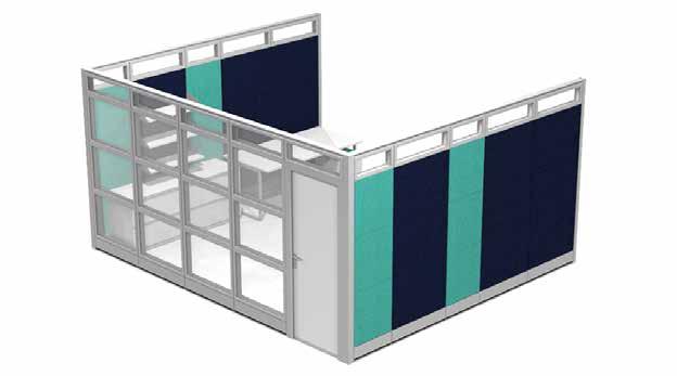
1 Installation Guide 84 H and 95 H
2 Stacker Bracket Connectors for topper of the wall system Step 1: (for 95 H and 108 H only) Attach glass topper to the wall system using the bracket shown (84 H wall system will not need a topper). Please attach stacker brackets and topper before putting panels together. Topper Stacker Bracket Stacker Bracket Screws (will be screwed into bracket from inside, should be done before frame is put together) *95 H wall system will have a 11 H topper *108 H wall system will have a 24 H topper 1
3 Installing Wall Starter Wall Starter Track No pre-drilled holes. Please use sheet metal screws and tap holes through frame. 1 1 Fix the side groove into wall 40 mm adjustable depth Wall Starter A mill away 50mm A Insert the side pole to the side groove. Side pole is processed as photo and fixed with panel connectors. 2
4 Direct Wall Mount Leveling and Connecting Your 1st Panel to a Wall Starter Step 3 Use M8*40 bolt to connect side pole and frame Step2 Adjust the adjuster 5mm up to keep space for adjustment in the further assembling *Make sure it s level 5mm Leveler 3
5 Direct Panel Mount Screws straight into the wall 5mm Leveler 4
6 2. Connect the frames by M8*30 bolt Top Track! same height 1. Adjust all frames into same level 5
7 *All connectors simply bolt into panels. 4 ways connection 3 ways connection Straight Connector 2 ways connection 120 degree 2 ways connection 120 degree 3 ways connection Connect the partition and column by M8*20mm bolt 6
8 End Trim Attach End Trim to Wall system No pre-drilled holes. Please use sheet metal screws (gold screws) and tap holes through frame. Gold Screws 7
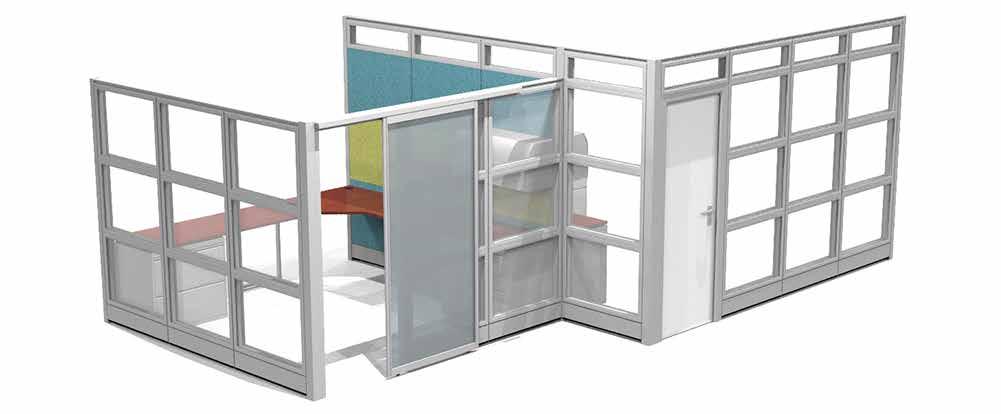
9 90 L Installing Swinging Door Frame How to Fix the Door Frame: 1. Fix the door frame material (45 cutting) with enhanced pole. 2. Fix the left and right door frame material with partition frame with screws in through the panels into the 3. Fix the top door frame material with L brackets, and insert it to the left and right door frame material. 4. Fix the partition frame above the door to the left and right partition frames. 5. Fix the hinges and sealings. 1 Door Frame with Partition Frame Door Frame with Side Pole Fix the L-Shape Aluminum Bracket Screw in through the panel into the door frame 5 2 L 3 4 8
10 1. Arrange Door Frame pieces on the floor in the correct positions that they will be put togther. TOP Door Frame Assembly A. FILLER SIDES FILLER B. 2. A. Screw in Top piece to side pieces using 1 screws (not self tapping). B. Then insert Fillers into sides with groove side up. 3. Insert Door Frame 59
11 90 4. Make sure Door Frame is level Door Frame Assembly L L 5. While tiles are o he wall, screw in through the panel to the frame with 1 1/2 self tapping screws. (7ft H walls this is the final step for the door frame assembly. 8ft H walls need to be screwed in from the top as well.) * 8ft 7ft *Only screw door frame in from top if setup is 8ft High 10
12 Swing Door Lock Assembly How to define door orientation Assembly Step One screw Left Open Door Right Open Door lock body door body Assembly Step Two Assembly Step Three buckle groove lock buckle screw 11
13 Installing the tile hook Screws Hook L R R L Fix the tiles 12
14 Top Groove Panel Stabilizer *May sometimes be needed to cut to size. 1 1/2 Sheet Metal Screws 1 1/2 Sheet Metal Screws 7 H Custom Panel 84 11/16 (with top cap) 83 3/8 2 1/2 13
15 Top Groove Panel Stabilizer *May sometimes be needed to cut to size. Cut stabilizers to overlap seam of panels Do not let stabilizers connect at the seam of the panel frame 14
16 1. Screw in Sliding Door Track Clips into grooves between panels. (Door Rail must be placed 83 3/4 from the ground measuring from the bottom of the rail to the ground.) 2. Sliding Door Assembly Place Sliding Door Rail onto screwed in Sliding Door Rail Clips and screw in from below. Door Rail must be placed 83 3/4 from the ground. A B 83 3/4 83 3/4 C B 3. Place Sliding Door Bottom Track on floor using double sided tape, 4. After inserting the Sliding velcro, or glue; Lining it up with the Door into the rail, Secure Stopper Door Rail. Then proceed to place in on the end. Sliding Door. D 5. Place Sliding Door Rail Finish Cap(s). Parts: E A B C D E 15


17 ! FINAL CONNECTION IS DONE BY A LICENSED ELECTRICIAN. WARNING: Risk of Fire or Electrical Shock. As with all non-directional systems, Do Not electrically connect panel to more than one supply source. Always determine that the panel is electrically connected to one and only one source of supply. Before using any equipment, check the entire system for polarity, continuity, and grounding integrity. Electric Setup Quad Power Modual 8w - 4c Flex Cables red in 3 1, 5 4, and 68 FIG 1 ***Outlet size: 325*** 3 H Blue 3 G Green/Yellow G Green 3 N Gray N White 1 H Bla ck 2 H Red 4 H Pink 3 IG Base Power Feed New York City Version of base power-in New York City versions of the cable-management panels are available to comply with the special installation requirements of the New York City electrical code. Chicago Panels sold with NO ELECTRIC. Power Supply Connection The Power System is an eight wire system consisting of four individual circuits rated at 20amps/120 volts maximum. Circuit 1 (black), circuit 2 (red), and circuit 4 (pink), are served by a system neutral (white) and an equpiment ground (green). Circuit 3 (blue) uses an isolated neutral (gray), and an isolated ground (green/yellow). The system may be supplied by a three phase power system with four individual circuits rated 20 amps/120 volts maximum, or as perimtted by local code. Building Electric In Feed When connecting electric pass throughs to power moduals, please make sure ARROW is up! Base Power Feed Hinged Racetrack door open to show area for electric and wired management Outlet Layout Options: O1 O2 Shown with Electric Module and Data O3 Shown with Electric (you can order 1, 2, or 3 and dedicated outlets) O4 O5 OUTLET - BLANK - BLANK OUTLET - OUTLET - BLANK OUTLET - OUTLET - OUTLET OUTLET - DEDICATED* - BLANK O6 *PLEASE NOTE: Orange is used to represent the Dedicated Outlet. The Dedicated Outlet color is BLACK. OUTLET - DEDICATED* - OUTLET BLANK - DEDICATED* - BLANK SAPPHIRE Cubicles come with Style #325 Outlets. 16
18 Data Setup Options DM1 DM2 DM3 CAT 6 CAT 6 CAT 6 CAT 6 CAT 6 CAT 6 CAT 6 - Blank - Blank - Blank CAT 6 - CAT 6 - Blank - Blank CAT 6 - CAT 6 - CAT 6 - Blank DM4 DM5 DM6 CAT 6 CAT 6 CAT 6 CAT 6 CAT 6 CAT 6 CAT 6 CAT 6 - CAT 6 - CAT 6 - CAT 6 CAT 6 - Phone Jack - Blank - Blank CAT 6 - CAT 6 - Phone Jack - Blank DM7 CAT 6 CAT 6 CAT 6 CAT 6 - CAT 6 - CAT 6 - Phone Jack All Modules can be customized to customers specifications. Please call to review options with one of our sales representatives. Color of jacks may vary. 17
x2 1/4 (6mm) Floor Anchor
 Floor Anchor") INSTALLATION GUIDE Main Components x1 Rail x5 Wall Spacer x2 Anti-jump Block x2 Straight Strap x1 Right Stopper x1 Left Stopper x5 5/16 (8mm x 60mm) Carriage Bolt x5 5/16 (8mm x25mm) Anchor x5 5/16 (8mm
INSTALLATION GUIDE Main Components x1 Rail x5 Wall Spacer x2 Anti-jump Block x2 Straight Strap x1 Right Stopper x1 Left Stopper x5 5/16 (8mm x 60mm) Carriage Bolt x5 5/16 (8mm x25mm) Anchor x5 5/16 (8mm
Office Partitions WARNING. Assembly Instructions. Customer Service A S S E M B LY HARDWARE H1 H2 H3 H4 H5 H8 H9 H10 H11 H12
 Customer Service 1-800-645-2986 Assembly Instructions WARNING In order to prevent structural failure, instability, t i p - o v e r, and/or serious injury, please follow i n s t ructions care f u l l y.
Dublin Stalls Installation Instructions
 Dublin Stalls Installation Instructions RAMM Horse Fencing and Stalls 13150 Airport Hwy. Swanton, OH 43558-9615 1-800-434-8456 Rev. 9/13/17 Part Identification Round Track Bracket (4) (Not Painted) Round
Assembly Instructions
 InTandem Table System November 20 InTandem Table System - Worksurface #4 x/" 4 wood screw power beam Tools Provided T-0 Extended Torx Driver T-25 Torx Driver Additional Tools Required Soft protective
Door window. Front door window, assembly overview
 64-50 Door window Front door window, assembly overview 1 - Window channel Pushed onto flange 2 - Door window Removing Page 64-52 Adjusting Page 64-53 3 - Door 4 - Outer window channel Pushed onto flange
Interra Installation Manual
 Interra Installation Manual Instructions to install the Friant Interra panel system Friant & Associates, LLC Table of Contents Getting Started Introduction... 3 General Tools, Staging & Safety... 4 Before
Hover. Installation Instructions. Raised Panel. Version
 Installation Instructions Version 8-2-17 Raised Panel Table of Contents Page Raised Panel Trough 3-13 Platform Trough 14-20 Platform 120 Degree Trough 21-24 Electrical 25-28 Type A Electric Bases 29-31
Figure A. Figure B. Figure C. Figure D
 Xsite 1 Power/Data Tile and Components Tools Required Tape Measure Cordless Drill/Driver #2 Phillips Screw driver bit Rubber Mallet Flat Blade Screwdriver Figure A Hardware Required Provided as shown Installation
On the Right Track. Installation Guide
 On the Right Track Installation Guide Table of Contents General Introduction Introduction...1 Local Building Codes...1 Tools Required...1 Additional Assistance...1 Parts Glossary Components...2 Track...5
Installation Manual for Metal Toilet Partitions Standard Series
 For Video instructions http://www.hadrian-inc.com/tech-data/installation/toilet-partitions.aspx P a g e 1 Table of Contents Page General Notes and Tools Required 3 STEP 1: Establish Floor Bracket Locations
BARN DOOR HARDWARE KIT
 INSTALLATION GUIDE Main Components x1 Rail x5 Wall Spacer x2 Anti-jump Block x2 Bent Strap x1 Right Stopper x1 Left Stopper x5 5/16 (8mm x 60mm) Carriage Bolt x5 5/16 (8mm x25mm) Anchor x5 5/16 (8mm x
Installation Manual for Metal Toilet Partitions Elite & Elite Plus Series
 P a g e 1 Table of Contents Page General Notes and Tools Required 3 STEP 1: Establish Floor Bracket Locations 4 STEP 2: Fasten Floor Brackets 4 & 5 STEP 3: Erect Panels 6 STEP 4: Erect Wall Pilaster 7
x2 1/4 (6mm) Floor Anchor
 Floor Anchor") Main Components x1 Rail x5 Wall Spacer x2 Anti-jump Block x2 Bent Strap x1 Right Stopper x1 Left Stopper x5 5/16 (8mm x 60mm) Carriage Bolt x5 5/16 (8mm x25mm) Anchor x5 5/16 (8mm x 90mm) Wall Screw x2
Main Components x1 Rail x5 Wall Spacer x2 Anti-jump Block x2 Bent Strap x1 Right Stopper x1 Left Stopper x5 5/16 (8mm x 60mm) Carriage Bolt x5 5/16 (8mm x25mm) Anchor x5 5/16 (8mm x 90mm) Wall Screw x2
Revised
 Indentify Non-powered panels and separate from Powered panels. Non-powered panel shown at left.. Powered panel shown at left has powerway mounted at factory. Also separate panels by surface type, width
a.k.a. casegoods instructions
 a.k.a. casegoods instructions a a.k.a. workwall installation IMPORTANT NOTES Failure to install product according to installation instruction will result in loss of warranty. Tools required for assembly
Modular & Hardwired Hub Assembly to "X" and "Y" Posts
 Modular & Hardwired Hub Assembly to "X" and "Y" Posts Hardware Package T-Nut Data jack bracket #6 x 1/4" plastite trilobular screw 1/4-20 x 3/4" socket head cap screw #6-32 x 1/4" pan head screw #10-32
Pathways Privacy Wall Glass Selections - Sliding Door
 Pathways Privacy Wall Glass Selections - Sliding Door #2 ACR BIT 3/16" HEX BIT RAYBO ETCHED GLASS STYLES: Satin Mist PATTERN GLASS STYLES: Waterfall Bamboo Harp Mirage If you have a problem, question,
Assembly Instructions
 Unite Panel System Hinge Door July 2016 #12 x / slotted hex washer head bolt Figure 1 threshold bracket frame Detail F threshold bracket threshold bracket (installed) #12 x / slotted hex washer head bolt
OXYGEN INSTALLATION. Revision date
 12345 1 Hardware List 12345 Flat head wood screw #9 x 7/8 long with #2 Phillips drive, silver Used to attach surfaces and end panels Hex set screw ½-13 x 2 long with 1/4 hex drive, black Used on Legs Hex
Yardistry. External Display YP *Time required for assembly approximately 1.5-2hrs
 Yardistry External Display YP40030 *Time required for assembly approximately 1.5-2hrs Components 4 Packages of Panel Clips (Includes 6 Panel Clips and Hardware) 3 16 1/2 x 16 1/2 Signs (hardware Included)
COURTYARD DOOR CANOPY INSTALLATION INSTRUCTIONS
 COURTYARD DOOR CANOPY INSTALLATION INSTRUCTIONS Recommended Tools: Electric Drill w/ Bits, Rachet or Nut Driver w/ Sockets, Level, Tape Measure, Screw Drivers (Phillips & Regular), Ladder Before You Begin:
Angled Side Flush with Panel Face
 Identify and sort panels by like sizes, fabrics, surface type (tackable vs hard), and NON- POWERED vs POW- ERED. Non-powered panels ship without a powerway. Powered panels include a powerway. See below.
Tools Needed Hardware Provided (per shade) Hardware Needed
 Hardware Needed") Baby Grande or Grande Motorized (XQ5 Premium) Shade with Cables and Housing Installation Instructions Tools Needed Hardware Provided (per shade) Hardware Needed Drill 3/8 Metal Drill Bit Measuring Tape
Baby Grande or Grande Motorized (XQ5 Premium) Shade with Cables and Housing Installation Instructions Tools Needed Hardware Provided (per shade) Hardware Needed Drill 3/8 Metal Drill Bit Measuring Tape
Figure #1 - VSNEO Shower Door Assembly
 Figure #1 - VSNEO Shower Door Assembly Figure #2 - VSNEO - Top View Figure #3 - VSNEO - Side View Figure #4 - Foam Curb Plug Figure #5 - Magnet Strip Figure #6 - VSNEO - Drip Deflector Preparation VSNEO
Vinyl Fence Products. Installation Guidelines. Hyde Park with H-Post Fence
 Vinyl Fence Products Installation Guidelines Hyde Park with H-Post Fence Hyde Park with H-Post Privacy Fence 1. Getting Started Be sure to call underground prior to digging Assemble gates (if necessary)
Box Track INSTALLATION INSTRUCTIONS
 Box Track INSTALLATION INSTRUCTIONS BOX TRACK Recommended Tools Level Tape Measure Pencil Drill with 1/8, and 1/4, Drill Bits, Phillips Bit and Slotted Bit Socket Wrench with 9/16 Socket 9/16 and 5/8 Wrench
Installation Manual for Metal Emperor Lockers
 P a g e 1 Table of Contents Page General Notes and Tools Required 2-3 Assemble Shelves with Coat Hooks/Coat Rods 4 Fastening Chart 5 Knock Down Locker Assembly (Banks of Three) 6-12 Appendix A: Dress End
Series 1500 Aluminum Door Canopy
 Series 500 Aluminum Door Canopy with Sidewings It is our recommendation that you read instructions carefully prior to assembly and installation. Series 500 with Sidewings mounting bar (A) top trim (B)
Continuous Handrail Kit Installation Instructions
 Continuous Handrail Kit Installation Instructions ALUMINUM RAILING SYSTEM Canadian Version Wall Application (see page 2) Railing Application (see page 7) Wall anchors not provided Hardware included: 1x
MODELS: AE46, AE42, E46, E42, ANE46, ANE42, NE46, NE42
 Installation Manual MODELS: AE46, AE42, E46, E42, ANE46, ANE42, NE46, NE42 TABLE OF CONTENTS SWIVEL UNITS (AE46, AE42, ANE46, ANE42)...pg.3 NON-SWIVEL UNITS (E46, E42, NE46, NE42)...pg.11 ELECTRICAL INSTRUCTIONS...pg.17
ASSEMBLY INSTRUCTIONS MANUAL
 PAGE 1 OF 9 RECOMMENDED TOOLS FOR ASSEMBLY: ALLEN WRENCH (INCLUDED) BOX WRENCH (INCLUDED) PHILLIPS SCREW DRIVER (NOT INCLUDED) PARTS IN CARTON: ALLEN WRENCH SCREWS (20 EACH) ROUND HEAD SCREWS (8 EACH)
BSM, GSM & GSS. Joint Kit Instruction. (Modified for IMPACT) (NSF Certified) Curved Glass Fresh Meat Delicatessen and Seafood Merchandisers
 (NSF Certified) Curved Glass Fresh Meat Delicatessen and Seafood Merchandisers") BSM, GSM & GSS Joint Kit Instruction (Modified for IMPACT) (NSF Certified) Curved Glass Fresh Meat Delicatessen and Seafood Merchandisers February, 1999 JOINT ASSEMBLY PARTS LIST Item Quantity Description
BSM, GSM & GSS Joint Kit Instruction (Modified for IMPACT) (NSF Certified) Curved Glass Fresh Meat Delicatessen and Seafood Merchandisers February, 1999 JOINT ASSEMBLY PARTS LIST Item Quantity Description
Quick Fit Installation Guide Retractable Screen - Double Door
 Quick Fit Installation Guide Retractable Screen - Double Door 1 REMOVE KIT PARTS FROM SHIPPING TUBE 2 Slide bolts 2 Rail receiver Clips 15 Mounting screws 1 Housing end cap screw 2 Handles 1 Housing end
Oxford Stalls Installation Instructions
 Oxford Stalls Installation Instructions RAMM Horse Fencing and Stalls 13150 Airport Hwy. Swanton, OH 43558-9615 1-800-434-8456 Rev. 8/15/17 Before You Start Typical stall sizes are 10 x 10, 12 x 12 or
Mirage Installation Manual
 Mirage Installation Manual General Information This installation manual provides necessary information for the safe installation of the Mirage product. WARNING: Failure to follow the instructions in this
User Instructions Multiline Otter Scoreboard Caddy Assembly
 List of parts: User Instructions Multiline Otter Scoreboard Caddy Assembly Single Caddy Double Caddy 1 1 Base assembly with attached wheels 2 4 1 1 2 4 4 8 10 20 12 Uprights (60 or 74 aluminum extrusion)
TrendWall Floor-To-Ceiling Panels Installation Instruction
 TrendWall Floor-To-Ceiling Panels Installation Instruction TrendWall Components Covered by this Instruction: Crown (and accessories) Floor Plate Solid Panel Filler Panel Wall Channel Door Section Pilaster
ROS-APT Caucus Plinth Table with Trough Note: Details apply, however the actual configuration of your table may vary from what is depicted here.
 ROS-APT Caucus Plinth Table with Trough Note: Details apply, however the actual configuration of your table may vary from what is depicted here. Parts List - Tables Tops, Top Insert Panels and Base panels
How To Measure Your Finished Opening
 3000 Series Bifold Doors How To Measure Your Finished Opening MEASURE FROM RIGHT TO LEFT 2 PLACES (WIDTH) MEASURE FROM TOP TO BOTTOM 2 PLACES (HEIGHT) Tools Required for Assembly: Tools Needed: Phillips
END FEED INSTALLATION
 STARLINE PLUG-IN RACEWAY END FEED INSTALLATION The Universal End Feed (product numbers beginning with URPF, URDF, or MRPF, MRDF) provides the installer a provision to connect supply power to the Plug-In
GE Monogram. Installation. Instructions. Microwave Oven. Under Cabinet Installation. and. JX827 Series Built-In Kit. Models.
 GE Monogram Installation Instructions Under Cabinet Installation and JX827 Series Built-In Kit Models ZEM200 Series CAUTION WARNING Before you begin Read these instructions completely and carefully. IMPORTANT:
Quick Fit Installation Guide Retractable Screen - Single Door
 Quick Fit Installation Guide Retractable Screen - Single Door 1 REMOVE KIT PARTS FROM SHIPPING TUBE 15 Mounting screws 1 Housing end cap screw 2 Handles 1 Housing end cap 1 Bushing 1 Pull bar end cap 2
Baby Grande with Crank, Housing, and Side Rails Installation Instructions
 Baby Grande with Crank, Housing, and Side Rails Installation Instructions Tools Needed Hardware Provided (per shade) Hardware Needed Drill 3/8 Metal Drill Bit ¼ Masonry Drill Bit Measuring Tape Pencil
MC CHANGER CABINET INSTALLATION INSTRUCTIONS
 8M00356 REV. 10 www.standardchange.com 1-800-968-6955 Technical Phone Support is from 8:00AM to 7:30PM E.S.T., Monday-Friday Walk-in Service is from 8:00AM to 4:30PM E.S.T., Monday-Friday Parts Department
86-1/2" TRACK INSTALLATION GUIDE
 BARN TRACK 86-1/2" TRACK INSTALLATION GUIDE READ ALL INSTRUCTIONS AND REVIEW DIAGRAMS BEFORE BEGINNING THE INSTALLATION TO GET A THOROUGH UNDERSTANDING OF THE PROCESS. BEFORE YOU BEGIN This kit comes with
INSTALLATION INSTRUCTIONS KK-K9-F14-K K9 KIT FOR FORD EXPEDITION
 INSTALLATION INSTRUCTIONS KK-K9-F14-K-32 32 K9 KIT FOR 2003-2016 FORD EXPEDITION TOOLS REQUIRED: Power Drill Drill Bit Set Standard & Metric Socket Sets Phillips Screw Driver Open End Wrench Set Wire Cutters
Bunk Pod Front Entry Assembly Instructions
 Bunk Pod Front Entry Assembly Instructions www.podtime.co.uk enquiries@podtime.co.uk Working House Ltd How to assemble your pod This step by step guide will show how to assemble your pod(s) on site. It
NOTE: Top section pole (Q) is packed INSIDE bottom section pole (S)
 is packed INSIDE bottom section pole (S)") Form 0905-0 Instructions and Parts List TM- Mini Castle (modified) MARTIN SAFETY SYSTEM NOTES: () A complete system is packed in two boxes post box and house box. House box contains hardware for both post
Form 0905-0 Instructions and Parts List TM- Mini Castle (modified) MARTIN SAFETY SYSTEM NOTES: () A complete system is packed in two boxes post box and house box. House box contains hardware for both post
Senior Swing. Caution
 *740132* 740132 2800 Overhead Concealed Series 9500 Surface Applied Series Senior Swing Installation Instructions Caution LCN Senior Swing The Senior Swing Power Operator System is a low energy product
INSTALLING INVISIRAIL GLASS PANELS POST INFORMATION... 2 PRE-INSTALLATION... 2
 Contents POST INFORMATION... 2 PRE-INSTALLATION... 2 STEP A1: MEASURING FOR INVISIRAIL CUSTOM GLASS PANELS (skip if using Standard Sized Panels)... 2 STEP A2: GATHER ADDITIONAL TOOLS/SUPPLIES... 2 STEP
Installation Manual. Solid Plastic Toilet Partitions. IN CANADA & AREAS OTHER THAN U.S.A.: IN THE U.S.A.:
 Installation Manual Solid Plastic Toilet Partitions Toilet Partitions & Lockers IN THE U.S.A.: Hadrian Inc., 7420 Clover Avenue, Mentor, OH 44060 Telephone: 440-942-9118 Fax: 440-942-9618 U.S. toll free
Installation Introduction
 Installation Guide Installation Introduction The On The Right Track system is a very versatile system, it can being installed several different ways and on various ceiling types. Here are the installation
Dura-Lock Roof System
 DLR-14 Dura-Lock Roof System Assembly and Installation Instructions Read the instructions before starting the job. They explain the steps required to produce a finished product that will meet factory specifications.
Aluminum Pre-Built Fence For Standard & Heavy-Duty Series
 ALUMFENCEA-BOM Aluminum Pre-Built Fence For Standard & Heavy-Duty Series INSTALLATION INSTRUCTIONS Read all instructions prior to installing product. Refer to manufacturers safety instructions when operating
1 of 2 3/3/2017 4:49 PM
 1 of 2 3/3/2017 4:49 PM Front Door Window, Assembly Overview 1 - Window guide - Inserted on flange 2 - Door 3 - Inner window recess seal - Inserted on flange 4 - Bolt - 20 Nm 5 - Carrier assembly - Window
Answer Power Beam and Boundary Screen
 Answer Power Beam and Boundary Screen 5/16 MAGNETIC 3/8 If you have a problem, question, or request, call your local dealer, or Steelcase Line 1 at 888.STEELCASE (888.783.3522) for immediate action by
Cabinet Mount Lifter Instructions
 PART LIST 2 @ Side Pivot Arms 1 @ Coupler Tube 1 @ Left Hand Bracket 1 @ Right Hand Bracket 2 @ Cover Support Arms w/ Foam Grip 1 set of Cover Saver 4 @ 4 Wood Screw 8 @ 1 Wood Screw 12 @ 1 Black Tek Screw
GE Monogram. Installation. Instructions. 27" Built-In Ovens. Models ZEK757WW ZEK757BW ZEK737WW ZEK737BW
 GE Monogram Installation Instructions 27" Models ZEK757WW ZEK757BW ZEK737WW ZEK737BW CAUTION WARNING Before you begin Read these instructions completely and carefully. IMPORTANT: Save these instructions
Hawko LED Flex & Accessories Installation Instructions
 LED Flex & Profiles Hawko LED Flex & Accessories Installation Instructions Contents Installation of IP20 LED Flex 4 Installation of IP67 LED Flex 6 Mounting Channel Installation 8 Mounting Clip Installation
Octagon Vinyl Gazebo Assembly Instructions For 10 & 12 Models
 Octagon Vinyl Gazebo Assembly Instructions For 10 & 12 Models Toll Free: 866.768.8465 Hours: 9-5 Monday-Friday EST www.homeplacestructures.com Package ships as shown revised 04/29/09 Vinyl Gazebo Assembly
Height Adjustable Benching End Panel and Utility Pole
 Height Adjustable Benching End Panel and Utility Pole Tools required: END PANEL Jig Saw Power Drill END PANEL WITH UTILITY POLE Bit Holder Long #2 Square Drive Bit 5mm Hex Drive Bit UTILITY POLE Level
Line volt rail & fixtures. Low volt quick connect fixtures with transformers
 INSTRUCTIONS: Line Volt Flexrail2 Safety Instructions: A qualified electrician must install system only. System is intended for installation in accordance with National Electric Code, local and Federal
INTRODUCTION Tools Required Laminate Washroom Products... 4 DUCT PANELS Fixing the Frame: Fixing the Shadow Panels...
 Contents INTRODUCTION... 2 Tools Required... 3 Laminate Washroom Products... 4 DUCT PANELS... 4 Fixing the Frame:... 5 Fixing the Shadow Panels... 9 Fitting the Duct Panels:... 10 WASHSTATIONS... 15 Fixing
CABINETRY Assembly Instructions
 www.hdicabinetry.com Assembly Instructions TABLE OF CONTENTS Category Page(s) Section 1: Framed Series Base Cabinet Instructions Wall Cabinet Instructions Easy Reach Cabinet Instructions 1.01-1.04 1.05-1.06
Baby Grande or Grande Crank Shade with Cables and Housing Installation Instructions
 Baby Grande or Grande Crank Shade with Cables and Housing Installation Instructions Tools Needed Drill 3/8 Metal Drill Bit Screwdriver (Flat & Phillips) Measuring Tape Pencil 4 Level Plumb Line ¼ Masonry
SECTION 19: Endwood Fusion Welded Gate Installation Guide
 SECTION 19: Endwood Fusion Welded Gate Installation Guide ASSEMBLY AND INSTALLATION FOR: Fusion Welded Gates Gate Frame with Full Size Pickets Privacy & Board on Board California & Shadowbox Gate width
Garage Door Frame Retro-Fit Clad Installation Instructions
 Garage Door Frame Retro-Fit Clad Installation Instructions Patent # US 7,111,433 B2, CA 2,415,545, Other Patents Pending Tools required Screw driver (screw gun), hammer, pry bar, tape measure, compound
Pergola Installation Instructions
 Pergola Installation Instructions TOOLS REQUIRED HAMMER DRILL 1/2 MASONRY BIT PENCIL DRILL 3/16 DRILL BIT LEVEL SQUARE LADDER WRATCHET & SOCKETS RUBBER MALLET 2 TAPE MEASURE Column/Post Placement Table
Household Appliances. Over-the-Range Microwave. Installation Instructions. For Models: HMV9302, HMV9305, HMV9306, HMV9307
 Over-the-Range Microwave Household Appliances Installation Instructions For Models: HMV9302, HMV9305, HMV9306, HMV9307 PLEASE READ ENTIRE INSTRUCTIONS BEFORE PROCEEDING IMPORTANT: Save these instructions
Assembly Instructions 10 X 10 Aluminum Roof Support
 Assembly Instructions 10 X 10 Aluminum Roof Support Aluminum Roof Support Bolt Package 16-5/16 X 2 ¼ SS Bolt 24-5/16 X 1 SS Bolt 40-5/16 SS Nylon Lock Nuts 16-5/16 SS Flat Washers 28-4 ½ Wood Screws 36-1
Assembly Instructions
 10' and 12' Octagon Cedar Gazebo Assembly Instructions Toll Free: 866.768.8465 Hours: 9-5 Monday-Friday EST www.homeplacestructures.com Package ships as shown revised 06/20/09 Cedar Gazebo Assembly Instructions
Contour Hanger ASSEMBLY INSTRUCTIONS
 Contour Hanger ASSEMBLY INSTRUCTIONS CONTOUR HANGER Recommended Tools Drill with 1/8, 1/4, and 3/8 Drill Bits, 1-1/8 Forstner Bit or 1-1/8 Spade Bit, and Phillips Bit 9/16 and 5/8 Combination Wrench Socket
Industrial Hanger ASSEMBLY INSTRUCTIONS
 Industrial Hanger ASSEMBLY INSTRUCTIONS INDUSTRIAL HANGER Recommended Tools Drill with 1/8, 1/4, and 3/8 Drill Bits, 1-1/8 Forstner Bit or 1-1/8 Spade Bit, and Phillips Bit 9/16 and 5/8 Combination Wrench
Thanks for shopping with Improvements! Deluxe 10 Closet Organizer (12 deep) Item #461609
 Item #461609") Thanks for shopping with Improvements! Deluxe 10 Closet Organizer (12 deep) Item #461609 To order, call 1-800-642-2112 West Chester, OH 45069 0114 If you have questions regarding this product, call 1-800-642-2112
Thanks for shopping with Improvements! Deluxe 10 Closet Organizer (12 deep) Item #461609 To order, call 1-800-642-2112 West Chester, OH 45069 0114 If you have questions regarding this product, call 1-800-642-2112
INSTALLATION INSTRUCTIONS
 INSTALLATION INSTRUCTIONS SHOWER STUDIO GLIDE Englefield has a history of making superb showers and their popularity is testament to their quality and affordability. It s the details that Englefield cares
PARTS INCLUDED IN FIXED STAIR CABLE RAIL KIT:
 175 SERIES FIXED STAIR CABLE RAIL - INSTALLATION INSTRUCTIONS PARTS INCLUDED IN FIXED STAIR CABLE RAIL KIT: FIXED STAIR TOP RAIL (1) A FIXED STAIR BOTTOM RAIL (1) B D UPPER SADDLE BRACKET (1) C BRACKET
Pocket Door Kit PD1 / PD2 Installation Instructions. Kit Contents.
 Pocket Door Kit PD1 / PD2 Installation Instructions Kit Contents. 1, Create Rough Opening In Stud Wall Construct rough opening ensuring all sides are square and level. Rough opening should be; Height =
TM12 ASSEMBLY INSTRUCTIONS
 TM12 ASSEMBLY INSTRUCTIONS Congratulations on purchasing the finest purple martin house available. Nature House Brand houses are the proven leader in aluminum martin housing for over half a century. After
 Section 3: Understanding Your Shop Drawings Reading Shop Drawing Abbreviations 60" O.A. stands for the overall dimension from the back wall to the front face of achieve your 60" overall you will set the
" BASE CABINET
 INSTALLATION GUIDE INSTALLATION GUIDE Before You Begin Installing Your Kitchen Cabinets 1. Read through installation guide to understand all steps and gather tools needed. 2. Verify that all of the hardware,
Side and rear window, assembly overview
 64-7 Side and rear window, assembly overview 1 - Side/rear window Removing Unbroken Page 64-9 Broken Page 64-11 Installing Page 64-13 Curing time Page 64-21 Re-sealing Page 64-25 2 - PUR adhesive sealant
Aluminum Frame Type Instruction Manual
 Aluminum Frame TypeInstruction Manual Thank you for selecting our product. Before starting installation, please read this manual thoroughly to ensure correct installation. Please keep this manual at hand
ZHONGSHAN KOHLER SHOWER CO., LTD. NO13-1, XINGYE ROAD, ZHONGSHAN TORCH DEVELOPMENT ZONE, ZHONGSHAN, GUANGDONG, CHINA POST CODE:
 NEW VERDERA INSTALLATION INSTRUCTIONS MIRRORED CABINET K-78202T-L/K-78202T-R/K-78282T BEFORE YOU BEGIN Please read these instructions carefully to familiarize yourself with the required tools, materials,
3.2.3 Rear Door Window and Quarter Window Carrier Assembly
 Tighten all bolts. Tighten bolts marked -1- and -2- in specified sequence. Tightening torque: 8 Nm Remaining bolts can be tightened in any sequence. Insert door window -3- through window recess without
S INGLE CIRCU I T 120V. LABELING: cul listed. GES Track Components. Flex Connector GES 23 GES 17. Dead Ends GES 41. (use with any connector)
") S INGLE CIRCU I T 120V G E S 1 CIR 120V Power supply for ElectraLED track lighting fixtures Architectural grade, extruded aluminum housing Milled grounding bar provides continuous ground contact Continuously
S INGLE CIRCU I T 120V G E S 1 CIR 120V Power supply for ElectraLED track lighting fixtures Architectural grade, extruded aluminum housing Milled grounding bar provides continuous ground contact Continuously
Ripple Hanger ASSEMBLY INSTRUCTIONS
 Ripple Hanger ASSEMBLY INSTRUCTIONS RIPPLE HANGER Recommended Tools Drill with 1/8, 1/4, and 1/2 Drill Bits, 1-1/8 Forstner Bit or 1-1/8 Spade Bit, and Phillips Bit 9/16 and 5/8 Combination Wrench Socket
INSTALLATION MANUAL VERITY. friant.com/verity
 INSTLLTION MNUL VERITY friant.com/verity 2 VERITY INSTLLTION MNUL General Information... 4 Safety & Support... 5 Installation Tools... 6 Staging & Installation... 7 Stand lone Units Single-Sided Structure...
TOOLS REQUIRED: HARDWARE INCLUDED: 13MM FLAT WRENCH FOR LEVELING THE STRUCTURE RATCHET WITH 5MM HEX BIT FOR CORNER SCREWS ON TOP TRAVERSE BEAMS
 1 TOOLS REQUIRED: RATCHET WITH 5MM HEX BIT FOR CORNER SCREWS ON TOP TRAVERSE BEAMS 13MM FLAT WRENCH FOR LEVELING THE STRUCTURE RUBBER MALLET FOR INSERTING PANELS 8MM HEX BIT WITH EXTENSION FOR HEX BOLT
Series 1100 Aluminum Door Canopy
 Series 00 Aluminum Door Canopy with Support Arms It is our recommendation that you read instructions carefully prior to assembly and installation. Series 00 with Support Arms MOUNTING BAR (A) TOP TRIM
TWIG Hanger ASSEMBLY INSTRUCTIONS
 TWIG Hanger ASSEMBLY INSTRUCTIONS TWIG HANGER Recommended Tools Drill with 1/8, 1/4, and 3/8 Drill Bits, 1-1/8 Forstner Bit or 1-1/8 Spade Bit, and Phillips Bit 9/16 and 5/8 Combination Wrench Socket Wrench
INS T A L L A TIO N INS T R U C TIO N S. Ceiling Mount Track System
 Ceiling Mount Track System 10.26.2016 Specifications Ceiling Post: Unassembled 2-7/8 Assembled 1-11/16 7/8 7-9/16 5-7/8 3/8 2 Tubes 1/2 2-3/8 5 Parts and Tools Tools Needed Tape Measure Pencil Drill with
compile system INSTALLATION GUIDE Updated January 2019
 INSTALLATION GUIDE Updated January 09 compile system Table of Contents Panels 0 Quick Connect Clips 0 Lock Clips 0 Panel Trims 0 Privacy Glass 0 Post Base Covers 04 Electrical 04 Power Distribution Harness
M10 x 75mm Sockethead Cap Screws. 5mm Fender Washer (12) Included - (8) Required. #10 x 2.5" PH Wood Screws. (30) Included - (24) Required
 Included - (8) Required. #10 x 2.5 PH Wood Screws. (30) Included - (24) Required") Door System Unit - Hardware Tools Included: (2) 2mm Allen Wrenches, (2) 3mm Allen Wrenches, (2) 4mm Allen Wrenches, (2) 6mm Allen Wrenches, and (1) 8mm T-Handle Allen Wrench Tools Required: Phillips Screwdriver,
Door System Unit - Hardware Tools Included: (2) 2mm Allen Wrenches, (2) 3mm Allen Wrenches, (2) 4mm Allen Wrenches, (2) 6mm Allen Wrenches, and (1) 8mm T-Handle Allen Wrench Tools Required: Phillips Screwdriver,
How to Install Custom Real Wood and Faux Wood Blinds
 Before you begin your installation: READ ALL INSTALLATION INSTRUCTIONS! Make sure that you have all tools and hardware needed for installation. Check the installation surface (wall, ceiling, or window
GLASS GLOBE MOBILE LINEAR CHANDELIER
 PARTS ENCLOSED: (B) Top ceiling plate [1] (C) Bottom ceiling plate [1] (D) Glass globes [7] (E) Screws [6] (F) Nuts [5] (G) Extension rods [15] (H) Transformer [1] (I) Threaded inserts [5] (J) 1.6W LED
Ready-To-Assemble VersaRail INSTALLATION INSTRUCTIONS
 FREEDOM-WEB Ready-To-Assemble VersaRail INSTALLATION INSTRUCTIONS Read all instructions prior to installing product. Refer to manufacturers safety instructions when operating any tools. To register your
Nocturne+ E INSTRUCTIONS CAUTION. Motor Operated Exterior Projection Screen. 1¾ (45mm) END CAP. Wall Mounting Bracket. Wall Mounting Bracket
 END CAP. Wall Mounting Bracket. Wall Mounting Bracket") Motor Operated Exterior Projection Screen Wall ing Bracket INSTRUCTIONS INSTALLATION & OPERATION CAUTION Wall ing Bracket 1. Inspect all boxes to make sure you have received the proper screen and parts.
Motor Operated Exterior Projection Screen Wall ing Bracket INSTRUCTIONS INSTALLATION & OPERATION CAUTION Wall ing Bracket 1. Inspect all boxes to make sure you have received the proper screen and parts.
Media Storage Systems Fixed Media Cabinets
 Owner s Manual Media Storage Systems Fixed Media Cabinets Contents 1-Column Fixed Media Storage Cabinet Important User Information...........................2 Safety Precautions.................................3
Thanks for shopping with Improvements! Serena File Cart with Charging Station Item #513376
 Thanks for shopping with Improvements! Serena File Cart with Charging Station Item #513376 Note: Read these instructions carefully before assembling. Tools required: Philips screwdriver (not included).
Baby Grande or Grande Crank Shade with Cables and Housing Installation Instructions
 Baby Grande or Grande Crank Shade with Cables and Housing Installation Instructions Tools Needed Drill 3/8 Metal Drill Bit Screwdriver (Flat & Phillips) Measuring Tape Pencil 4 Level Plumb Line ¼ Masonry