On the Right Track. Installation Guide
|
|
|
- Shawn Chandler
- 6 years ago
- Views:
Transcription

1 On the Right Track Installation Guide
2 Table of Contents General Introduction Introduction...1 Local Building Codes...1 Tools Required...1 Additional Assistance...1 Parts Glossary Components...2 Track...5 Installation - Ceiling Please select ceiling type and proceed to page 14 Installing into ACT 15/16 Exposed Grid...7 Installing into ACT 9/16 Exposed Grid with Recessed Tiles...8 Installing into Traditional Cubicle Curtain Track...9 Installing into Gypsum Board Ceilings...10 Installing into Plywood Ceilings...11 Installing into Concrete or Masonry Ceilings...12 Installing into a Wall/Soffit...13 Installation - Components Parts Assembly...14 Connecting the Track Connector...15 Connecting the Hanger & Track Connector...16 Connecting the End Cap...17 Connecting the End Wall Plate...18 Installing Rail Drops...19 Installing Ceiling Blocking...20 Appendix Graphical Track Layout...21 Graphical Track Layout with Drops...22 Graphical Ceiling Installation...23 Installation and Building Code for Concrete Anchor...25 Maintenance...33
3 General Introduction Introduction On The Right Track s worldwide patented cubicle curtain system includes a state-of-the-art track system that will give you years of ageless beauty and carefree enjoyment. The following illustrated instructions have been provided to help you understand and take advantage of various scenarios and their appropriate installation techniques. Following these instructions along with good building practices will deliver the highest quality installation. Failure to follow these instructions also risks voiding the OTRT warranty. Local Building Codes Please follow all building codes and good construction practices when installing the curtain track. In addition to local codes, be sure to follow the instructions in this guide. Failure to do so may void your OTRT warranty. Tools required Rubber mallet Phillips screwdriver Chop Saw with a non-ferrous aluminum blade or Hand Saw File Laser Level Measuring Tape TE-CX 1/4 x 6 Hammer drill bit (for concrete anchors only) HILTI 7/16 Drive Socket ( for concrete anchors only) Additional Assistance For additional assistance, be sure to view our installation videos at: Patent No.: US D669, 721S; 5,186,232; 6,494,248; 6,935,402; 7,296,609 CN C; UK 2,458,075 and other US/int l patents pending. 1
4 Parts Glossary Components Part # OPTS-B02 Hard Ceiling Mounting Plate Please Note: some earlier versions have 4 screw holes. ONLY 2 SCREWS ARE REQUIRED. One on each side diagonally Part # OPTS-C02 End Wall Plate Part # OPTS-D02 Hanger & Tube Connector Part # OPTS-C02-S Swivel Wall Plate Part # OPTS-F02 Track Connector Part # OPTS-E02 Hanger & Track Connector Please Note: some earlier versions have 4 screw holes. ONLY 2 SCREWS ARE REQUIRED. One on each side Part # OPTS-G02 Hanger Part # OPTS-J02 Extensible Square Tube 2


5 Part# OPTS-J02-SB Support Bracket for Drops Part # OPTS-M02 End Cap Part # OPTS-P02 Ceiling Vertical Mount Plate Part # OPTS-Q02 Room Divider Wall Mount Part # OPTS-S302 5/32 x 13mm self tap screw Part # OPTS-S02 Swivel Clip With Drop Ceiling Grid Mounting Plate Part #OPTS-S402 5/32 x 11/4 mount screw Part # OPTS-S602 5/32 x 16mm screw Part # OPTS-SP03 Part # OPTS-S102 5/32 x 8.2mm screw 3

6 OPTS-S802 Plastic Anchor Part # OPTS-S902-1 (5/32 x 1 screw) Part # OPTS-T02 Track Adapter Part # OPTS-UO2 Curtain Stopper Part# OPTS-W02 Ceiling Blocking Part# OPTS-AN-C 1/4 x 2 5/8 Anchor for Concrete and Masonry Part# OPTS-S602-CA 1/6 x 1-1/2 Self Tapping Screw for CA Part# OPTS-S802-W 1/4 x 1 1/2 Anchor 4
7 STRAIGHT TRACK Part # OPTS-H Ft Track Part # OPTS-H Ft Track Part # OPTS-H Ft Track Part # OPTS-H Ft Track 5
8 BENDS Part # OPTS-K Ft Radius Track Part # OPTS-K1R Reversed 1 Ft Radius Track Part # OPTS-K Ft Radius Track Part # OPTS-K2R Reversed 2 Ft Radius Track Part # OPTS K Ft Radius Track Part # OPTS-K Ft Radius Track (80% of semi-circle) Part # OPTS-K5R Reversed 5 Ft Radius Track Part # OPTS-L Ft Radius Track Part # OPTS-L1R Reversed 1 Ft Radius Track Part # OPTS-L Ft Radius Track Part # OPTS-L2R Reversed 2 Ft Radius Track 6

9 INSTALLING INTO ACT 15/16TH EXPOSED GRID Directions: 1. The Drop Ceiling Grid Mount is a two piece mount. The center of the mount can be positioned and locked in place prior to attaching to drop ceiling grid work. 2. The center of the mount can be placed in one of eight positions to accommodate installation needs, and align correctly. 3. Secure a Drop Ceiling Mount piece (part# OPTS-S02) to the ACT grid using 2 pieces of OPTS-S902-1 screws. 4. If using drops, use 2 pieces of OPTS-S902-1 screws into a Ceiling Vertical Hanger Mount Plate (part# OPTS-P02) If the drop is greater than 12, also attach a Support Bracket (part# OPTS-J02-SB) from the drop (part# OPTS-J02) to the ceiling. 15/16 th Drop ceiling grid Notes: The ceiling mount should be 6 away from the wall and then installed every 24. If this installation is in California and you are using drops, the maximum drop distance allowed is 24. ONCE COMPLETE, PLEASE GO TO PAGE 14. 7
10 INSTALLING INTO ACT 9/16 EXPOSED GRID WITH RECESSED TILES Directions: 1. The Drop Ceiling Grid Mount is a two piece mount. The center of the mount can be positioned and locked in place prior to attaching it to grid work. 2. Line up the hanger slot with the screw holes of the piece. 3. Secure a Drop Ceiling Mount piece (part# OPTS-S02) to the ACT grid using two OPTS-S902-1 screws and placing 2 spacers (part# OPTS-SP03) under neath each piece. 4. If using drops, use 2 pieces of OPTS-S902-1 screws into a Ceiling Vertical Hanger Mount Plate (part# OPTS-P03) If the drop is greater than 12, also attach a Support Bracket (part# OPTS-J02-SB) from the drop (part# OPTS-J02) to the ceiling. Notes: Using spacers will allow the Drop Ceiling Grid Mount to be installed without interfering with the recessed tiles. The ceiling mount should be 6 away from the wall and then installed every 24. If this installation is in California and you are using drops, the maximum drop dis tance allowed is 24. ONCE COMPLETE, PLEASE GO TO PAGE 14. 8
11 INSTALLING INTO TRADITIONAL CUBICLE CURTAIN TRACK Directions: 1. Insert the Track Adapter (part# OPTS-T02) into pre-installed traditional track. 2. Secure the Drop Ceiling Grid Mount (part# OPTS-S02) to the Track Adapter by using two OPTS-S602 screws. 3. if using drops, use 2 pieces of OPTS-S602 screws into a Ceiling Vertical Hanger Mount Plate (part# OPTS-P02) and Track Adapter (part# OPTS-T02). Notes: The ceiling mount should be 6 away from the wall and the installed every 24. If this installation is in California, you will need to also install an OPTS-S602-CA screw through one of the open holes on the Track Adapter (part# OPTS-T02) and all the way through both the traditional track and ceiling above it. If this installation is in California and you are also using drops, the maximum drop distance allowed is 24. ONCE COMPLETE, PLEASE GO TO PAGE 14. 9
12 INSTALLING INTO GYPSUM BOARD CEILINGS Directions: 1. Please check local city and state regulations regarding the installation into gypsum board ceilings before proceeding. 2. Attach a Hard Ceiling Mount Plate (part# OPTS-B02) to the ceiling using 4 pieces of OPTS-S802-W anchors. 3. If using drops, use 3 pieces of OPTS-S802-W anchors into a Ceiling Vertical Hanger Mount Plate (part# OPTS-P02) If the drop is greater than 12, also attach a Support Bracket (part# OPTS-J02-SB) from the drop (part# OPTS J02) to the ceiling. Notes: The anchors should be installed using a very low torque setting on your drill or with an ordinary Phillips screwdriver. DO NOT OVER-TORQUE SCREWS. A laser level is very useful when laying out locations for the hard ceiling mount plates. The ceiling mount should be 6 away from the wall and then installed every 24. If this installation is in California and you are using drops, the maximum drop distance allowed is 24. ONCE COMPLETE PLEASE GO TO PAGE
13 INSTALLING INTO PLYWOOD CEILINGS Directions: 1. Attach a Hard Ceiling Mounting Plate (part# OPTS-B02) to the ceiling using 2 pieces of OPTS-S802-W anchors. 2. If using drops, use 3 pieces of OPTS-S802-W anchors into a Ceiling Vertical Hanger Mount Plate (part# OPTS-P02). If the drop is greater than 12, also attach a Support Bracket (part# OPTS-J02-SB) from the drop (part# OPTS-J02) to the ceiling. Notes: The anchors should be installed using a very low torque setting on your drill or with an ordinary Phillips screwdriver. DO NOT OVER-TORQUE SCREWS. A laser level is very useful when laying out locations for the hard ceiling mount plates. The ceiling mount should be 6 away from the wall and then installed every 24. If this installation is based in California, the maximum drop distance allowed when installed into plywood substrate is 20. ONCE COMPLETE, PLEASE GO TO PAGE
 to the ceiling using 2 pieces of OPTS-AN-C an")
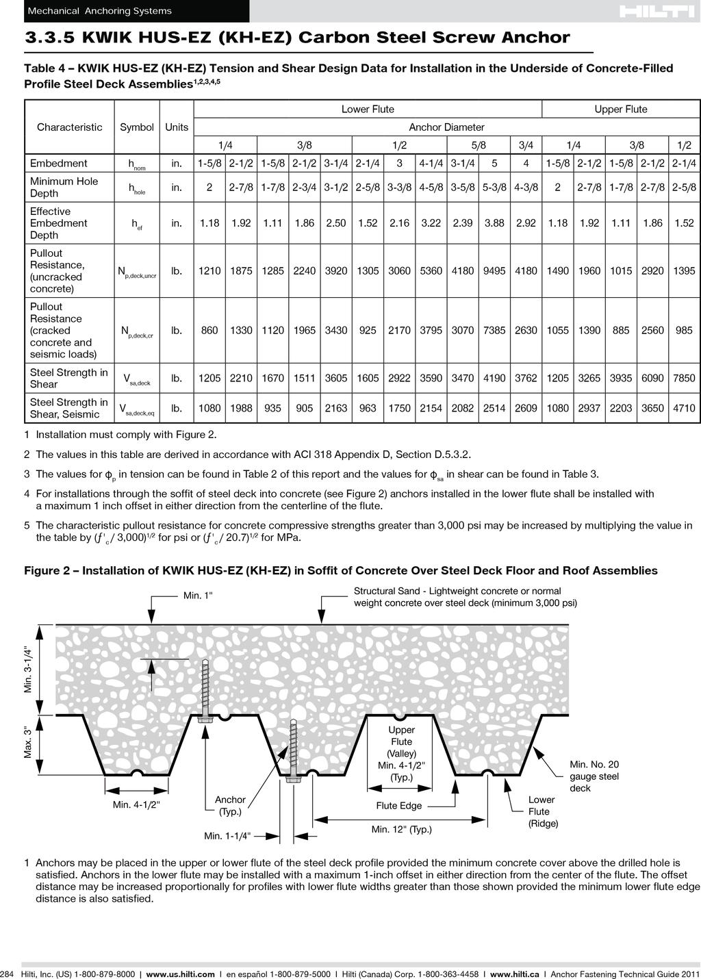
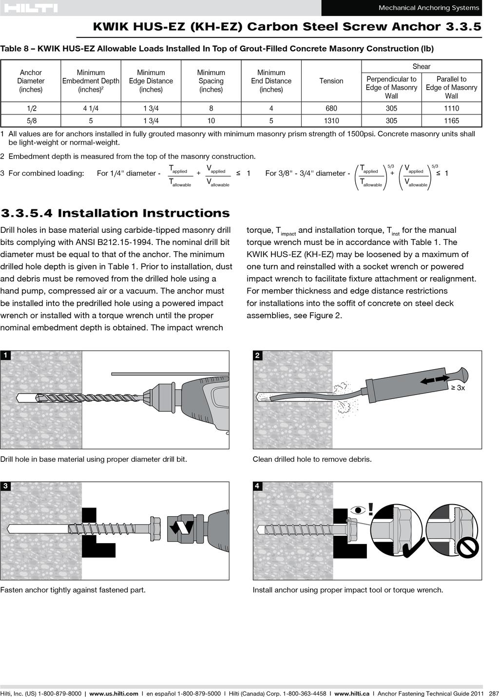
14 INSTALLING INTO CONCRETE/MASONRY CEILINGS Directions: 1. Attach a Hard Ceiling Mounting Place (part# OPTS-B02-CA) to the ceiling using 2 pieces of OPTS-AN-C anchors. a. In order to stay within code, please refer to the Appendix on page 25 for detailed anchor installlation instructions and building code information. 2. If using drops, use 1 piece of OPTS-AN-C anchor into a Ceiling Vertical Hanger Mount Plate (part# OPTS-P02) If the drop is greater than 12, also attach a Support Bracket (part# OPTS- J02-SB) from the drop (part# OPTS-J02) to the ceiling. Notes: A laser level is very useful when laying out locations for the hard ceiling mount plates. The ceiling mount should be 6 away from the wall and then installed every 24. In order to stay within code, please refer to the Appendix on page 23 for detailed anchor installation instructions and building code information. If this installation is in California and you are using drops, the maximum drop distance allowed is 24. ONCE COMPLETE, PLEASE GO TO PAGE

15 INSTALLING INTO A WALL/SOFFIT Directions: 1. Attach a Wall Mounting Plate (part# OPTS-Q02) to the wall using 2 pieces of OPTS- S802-W anchors. 2. After the Track and Hanger Connector (part# OPTS-E02) has been inserted into the back of the track, slide it on to the Wall Mounting Plate and secure it with an OPTS-S102 screw. Notes: The anchors should be installed using a very low torque setting on your drill or with an ordinary Phillips screwdriver. DO NOT OVER-TORQUE SCREWS. A laser level is very useful when laying out locations for the wall mount plates. The wall mount should be installed every
16 PARTS ASSEMBLY Directions: 1. Insert the Hanger (part# OPTS-G02) into the appropiate ceiling mount piece (dependent on ceiling type) and secure with an OPTS-S102 screw. Hard ceiling mount. Drop ceiling grid mount. Notes: Once all the Hangers have been installed, go back and insert the other ends into the Hanger & Track Connectors (part# OPTS-E02) installed on page 16. This is secured using an OPTS-S102 screw. The first hanger assembly (OPTS-G02) should be 6 away from the wall and then installed every
17 CONNECTING THE TRACK CONNECTOR Directions: 1. Join together two pieces of track by sliding the Track Connector (part# OPTS- F02) into each adjoining end of track. 2. Make sure the piece is all the way in and snug. You may need to use a rubber mallet to achieve this. 3. Once the piece is in place, secure with 2 pieces of OPTS-S102. Note: During the installation process, it may become necessary to cut the track in order to get a perfect fit. Be sure to take care in cutting the end of the track that does not join to another track. Manufactured/ finished ends of the track are ideal for joining with the Connector piece. Cut ends may be capped off at the end of the track by using an End Cap (part# OPTS-M02) or End Wall Plate (part#. OPTS-C02). Please see the below example for further clarification: Example:. Cut Cut Manufactured Manufactured 15
18 CONNECTING THE HANGER & TRACK CONNECTOR Directions: 1. Make sure the track is right side up. This will be evident by noting a smooth rounded top and a lip at the bottom. 2. Place the end of the Hanger & Track Connector (part# OPTS-E02) into the groove on the back side of the track and turn clockwise 1/4 turn. This will lock the piece into place. 3. If you need to reposition, simply reverse the process. 4. The other end of this piece connects to the hanger (part# OPTS-G02) that should be suspended from the ceiling (done earlier). This is secured using an OPTS-S102 screw. Note: The Hanger & Track Connector should only be turned in a clockwise direction. 16
")
19 CONNECTING THE END CAP To connect and End Cap (part# OPTS-M02), simply slide into place and secure with a self-tapping screw (part# OPTS-S302) 17

20 CONNECTING THE END WALL PLATE Directions: 1. To connect an End Wall Plate (part# OPTS-C02), simply slide into place and secure with a self-tapping screw (part# OPTS-S302) 2. Use 4 pieces of OPTS-S802-W anchors to secure the piece to the wall. Notes: Attaching this piece should be the last step in your installation. The first hanger assembly (OPTS-G02) should be 6 away from the wall and then installed every
21 INSTALLING RAIL DROPS Directions: 1. Insert an Extensible Tube (part# OPTS-J02) into the Ceiling Vertical Hanger Mount Plate (part# OPTS-P02). You may need a rubber mallet to completely insert the tube. This should be done before you attach the mount plate to the ceiling. Also be sure to insert the cut end into the plate (or the end that does not have a hole). 2. Secure with an OPTS-S302 screw. 3. Insert the other end of the tube into a Tube and Hanger Connector (part# OPTS-D02) making sure to align the holes. 4. Insert a Hanger (part# OPTS-G02) and secure with an OPTS-S302 screw. 5. If the drop is greater than 12, also attach a support bracket (part# OPTS-J02-5B) from the drop (part# OPTS-J02) to the ceiling. P02 S302 J02 S302 D02 G02 Notes: Our Extensible Tubes are used to drop the rail to a specific height. These come in 2 and 4 sizes and may need to be cut to size in the field before installation. The Mount Plate is designed to taper so that once the tube has been completely inserted, it will not flex. For instructions on installing the Ceiling Vertical Hanger Mount Plate (part# OPTS-P02) into the ceiling, please refer to the appropriate ceiling page in this manual. The ceiling mount should be 6 away from the wall and then installed every 24. If this installation is in California and you are using drops, the maximum drop distance al lowed is 20 when installed into plywood substrate, and 24 into other materials. 19
22 INSTALLING CEILING BLOCKING Directions: 1. Attach the round Swivel on a Hanger (part# OPTS-G02) and secure with an 11mm screw. 2. Clip a left and right Cover to the round Swivel. 3. Attach the left and right clips to the Cover and around the ACT grid. Then secure with a 6.2mm and a 27mm screw. Note: The ceiling mount should be 6 away from the wall and then installed every

23 OPTS-F02 OPTS-H302 OPTS-H402 OPTS-H502 OPTS-K102 OPTS-K202 OPTS-K1R02 OPTS-K2R02 OPTS-L102 OPTS-L202 OPTS-L1R02 OPTS-L2R02 OPTS-S102 x 2 pcs OPTS-B02 OPTS-E02 OPTS-S102 x 1 pcs OPTS-M02 OPTS-S302 x 1 pcs OPTS-S102 x 1 pcs OPTS-G02 21

24 OPTS-H302 OPTS-H402 OPTS-H502 OPTS-K102 OPTS-K202 OPTS-K1R02 OPTS-F02 OPTS-P02 OPTS-S302 x 1 pcs OPTS-J02 OPTS-S802-W x 4 pcs (Attach to Wall) OPTS-D02 OPTS-K2R02 OPTS-L102 OPTS-L202 OPTS-L1R02 OPTS-L2R02 OPTS-S302 x 1 pcs OPTS-C02 OPTS-S302 x 1 pcs OPTS-E02 OPTS-G02 OPTS-S102 x 2 pcs OPTS-S102 x 1 pcs 22
25 23
26 24
27 25
28 26
29 27
30 28
31 29
32 30
33 31
34 32
35 MAINTENANCE 33
Installation Introduction
 Installation Guide Installation Introduction The On The Right Track system is a very versatile system, it can being installed several different ways and on various ceiling types. Here are the installation
TrendWall Floor-To-Ceiling Panels Installation Instruction
 TrendWall Floor-To-Ceiling Panels Installation Instruction TrendWall Components Covered by this Instruction: Crown (and accessories) Floor Plate Solid Panel Filler Panel Wall Channel Door Section Pilaster
#11179 Wellington ARBOR
 #11179 Wellington ARBOR Assembly INSTRUCTIONS TOOLS NEEDED Tape Measure Variable Speed Drill with #2 Phillips Bit (recommended) or Phillips Screwdriver Hammer or Mallet ARBOR SIDE PANEL ASSEMBLY (Refer
Assembly and Installation Guide
 The Easy Hang Closet Solution SM Install Your elfa In An Instant. Enjoy The Benefits For A Lifetime. Basic Tools For elfa Assembly and Installation Level Hand or Power Drill Drill Bits 1/8", 3/8", 5/16"
Line volt rail & fixtures. Low volt quick connect fixtures with transformers
 INSTRUCTIONS: Line Volt Flexrail2 Safety Instructions: A qualified electrician must install system only. System is intended for installation in accordance with National Electric Code, local and Federal
TIP FOR GETTING STARTED
 Tip for getting started TIP FOR GETTING STARTED Be careful not to drill into any electrical wires, ductwork, plumbing or other damagable components. If you have any questions on the locations of these
DekPro Prestige Aluminum Rail System Level Railing Installation Instructions
 ing Installation Guide Please read all instructions completely before starting any installation of DekPro Prestige Railing Systems. SAFETY: Always be safe and follow all instructions when using power tools
x2 1/4 (6mm) Floor Anchor
 Floor Anchor") INSTALLATION GUIDE Main Components x1 Rail x5 Wall Spacer x2 Anti-jump Block x2 Straight Strap x1 Right Stopper x1 Left Stopper x5 5/16 (8mm x 60mm) Carriage Bolt x5 5/16 (8mm x25mm) Anchor x5 5/16 (8mm
INSTALLATION GUIDE Main Components x1 Rail x5 Wall Spacer x2 Anti-jump Block x2 Straight Strap x1 Right Stopper x1 Left Stopper x5 5/16 (8mm x 60mm) Carriage Bolt x5 5/16 (8mm x25mm) Anchor x5 5/16 (8mm
CertainTeed INSTALLATION GUIDE SIMTEK FENCE PRODUCTS. Fence Installation Guide 3', 4' & 6' High
 CertainTeed INSTALLATION GUIDE SIMTEK FENCE PRODUCTS Fence Installation Guide 3', 4' & 6' High INSTALLATION GUIDE These instructions are designed to assist both professional installers and do-it-yourselfers
Step by Step Installation Instructions. Poly Shutters. Customer Service or visit us online at smithandnoble.com
 Step by Step Installation Instructions Poly Shutters Customer Service 800.248.8888 or visit us online at smithandnoble.com Thank you for purchasing from smith+noble. Your new window treatments have been
McCue Bumper Installation Instructions
 McCue Bumper Installation Instructions McCue 8" Bumper Tools Required: Saw with 10-12" blade Tape measure Flat head screwdriver Phillips screw driver Pencil or chalk line Drill with Philips driver bit
Double Beam Freestanding Pergola Installation Guide
 Double Beam Freestanding Pergola Installation Guide Patent Pending. Copyright 2011 USAVinyl, LLC - All Rights Reserved The information contained in these instructions are proprietary to USAVinyl, LLC and
Installation Guide. 84 H and 95 H
 Installation Guide 84 H and 95 H Stacker Bracket Connectors for topper of the wall system Step 1: (for 95 H and 108 H only) Attach glass topper to the wall system using the bracket shown (84 H wall system
Baby Grande with Crank, Housing, and Side Rails Installation Instructions
 Baby Grande with Crank, Housing, and Side Rails Installation Instructions Tools Needed Hardware Provided (per shade) Hardware Needed Drill 3/8 Metal Drill Bit ¼ Masonry Drill Bit Measuring Tape Pencil
Display Shelving Installation Instructions
 Display Shelving Installation Instructions Top Rail (R-T) Back (BE) (R-C) Splicer Rail (R-S) 78 H to 120 H only Uprite (U) Uprite End Trim (UET) Shelf Back (BE) Base End Trim (BET) (R-C) 96 H to 120 H
Top Closure Kit Accessory for Music Library System
 Assembly Instructions Top Closure Kit Accessory for Music Library System Contents Required Tools.....................................2 Installation Requirements............................2 Fasteners -
How to Install Custom Real Wood and Faux Wood Blinds
 Before you begin your installation: READ ALL INSTALLATION INSTRUCTIONS! Make sure that you have all tools and hardware needed for installation. Check the installation surface (wall, ceiling, or window
Installation Instruction
 Tools Needed for Assembly Stud finder (for wood stud wall) Pencil Mark Electric drill Wood Stud Wall Installation Step 1. Locate the Wood Studs Installation Instruction Drill bit (for wood stud wall) Masonry
Figure A. Figure B. Figure C. Figure D
 Xsite 1 Power/Data Tile and Components Tools Required Tape Measure Cordless Drill/Driver #2 Phillips Screw driver bit Rubber Mallet Flat Blade Screwdriver Figure A Hardware Required Provided as shown Installation
9 X 9 REMOVABLE TYPE ALUMINUM WINDOW BARS INSTALLATION INSTRUCTIONS Import Note : 9 X 9 Spacing Removable Type Installation is covered in this
 Import Note : 9 X 9 Spacing Removable Type Installation is covered in this Instruction. Removable Bars Only Mount in Recess Position ( Between Window Jamb/ Frame ) The spacing between horizontal bars is
Box Track INSTALLATION INSTRUCTIONS
 Box Track INSTALLATION INSTRUCTIONS BOX TRACK Recommended Tools Level Tape Measure Pencil Drill with 1/8, and 1/4, Drill Bits, Phillips Bit and Slotted Bit Socket Wrench with 9/16 Socket 9/16 and 5/8 Wrench
Installation Instructions CR3/G2 BioBlend -3 Wood Chair Rail - Stock Length
 Important 1. Install product in environmentally controlled conditions. 2. Acclimate materials 24 hrs before installation. Maintain temperature controlled environment after installation. 3. Installers should
Baby Grande or Grande Crank Shade with Cables and Housing Installation Instructions
 Baby Grande or Grande Crank Shade with Cables and Housing Installation Instructions Tools Needed Drill 3/8 Metal Drill Bit Screwdriver (Flat & Phillips) Measuring Tape Pencil 4 Level Plumb Line ¼ Masonry
FABA. Installation Instructions. Conductor Bar System. Publication #FABA-03 3/1/04 Part Number: Copyright 2004 Electromotive Systems
 FABA Conductor Bar System Installation Instructions Publication #FABA-03 3/1/04 Part Number: 005-1062 Copyright 2004 Electromotive Systems 1S 100 Z Installation Instructions Contents: Basic Diagram - -
Bathroom Installation Guide
 Bathroom Installation Guide Please read instructions carefully and check products before starting. Products should be fitted/installed by an experienced and competent fitter, failure to do so may invalidate
Kwik-Lock. Installation Instructions. Attention Dealers: Please give this owners manual to the customer when the product is delivered.
 Serving the Truck & Trailer Industry Since 1944 Installation Instructions Attention Dealers: Please give this owners manual to the customer when the product is delivered. Call 800-535-9545 www.aeroindustries.com
Walk-in Configurations
 Walk-in Configurations Includes Wall-to-Open, Corners, and Corner Rounder Bars INSTALLATION INSTRUCTIONS Tools needed: Tape measure, level, pencil, #2 Phillips head screw driver or power drill with a 6"
Step by Step Installation Instructions. Poly Shutters. Customer Service or visit us online at smithandnoble.com
 Step by Step Installation Instructions Poly Shutters Customer Service 800.248.8888 or visit us online at smithandnoble.com THANK YOU for purchasing from smith+noble. Your new window treatments have been
BARN DOOR HARDWARE KIT
 INSTALLATION GUIDE Main Components x1 Rail x5 Wall Spacer x2 Anti-jump Block x2 Bent Strap x1 Right Stopper x1 Left Stopper x5 5/16 (8mm x 60mm) Carriage Bolt x5 5/16 (8mm x25mm) Anchor x5 5/16 (8mm x
RAIL 4 PERIMETER RP4D RECESSED T-BAR LED TELESCOPIC, INTEGRAL DRIVER
 INSTALLATION INSTRUCTIONS RAIL 4 PERIMETER RP4D RECESSED T-BAR LED TELESCOPIC, INTEGRAL DRIVER NOTE: The following instructions provide general guidelines for product installation. For additional information
NEPAL Installation procedure
 PART DESCRIPTION 1.- Door handle (1pc) 2.- Long tight bar (1pc) 3.- Short tight bar (1pc) 4.- Support block-lower (2pcs) 5.- Wall jamb cap (2pcs) 6.- Tight bar support (2 pcs) 7.- Acrilic base (1pc) 8.-
Installation Instructions HR910 Handrail
 Important 1. Acclimate materials 24 hrs before installation. Maintain temperature controlled environment after installation. 2. Install in accordance with manufacturer s installation instructions. Failure
INSTALLATION AND CARE INSTRUCTIONS
 INSTALLATION AND CARE INSTRUCTIONS Vertical Applications Honeycomb Shades 52 C8-10-3401 Rev 2/14 CONTENTS Introduction...2 Before You Begin...3 Vertical Application Parts Overview...4 Materials Required...5
Installation Instructions HR910 International Compliant Handrail
 Important 1. Acclimate materials 24 hrs before installation. Maintain temperature controlled environment after installation. 2. Install in accordance with manufacturer s installation instructions. Failure
Installation Instructions
 Important 1. Acclimate materials 24 hrs before installation. Maintain temperature controlled environment after installation. 2. Install in accordance with manufacturer s installation instructions. Failure
INS T A L L A TIO N INS T R U C TIO N S. Ceiling Mount Track System
 Ceiling Mount Track System 10.26.2016 Specifications Ceiling Post: Unassembled 2-7/8 Assembled 1-11/16 7/8 7-9/16 5-7/8 3/8 2 Tubes 1/2 2-3/8 5 Parts and Tools Tools Needed Tape Measure Pencil Drill with
Installation Instructions for. Handrail Component System
 Handrail STEP-BY-STEP Installation Instructions for Handrail Component System Rise in Inches Run in Inches 8 8.5 9 9.5 10 10.5 11 11.5 12 12.5 13 13.5 14 14.5 15 8.5 47 45 43 42 40 39 38 36 35 34 33 32
#11179 Wellington ARBOR
 #11179 Wellington ARBOR Assembly INSTRUCTIONS TOOLS NEEDED Tape Measure Variable Speed Drill with #2 Phillips Bit (recommended) or Phillips Screwdriver Hammer or Mallet ARBOR SIDE PANEL ASSEMBLY (Refer
Installation Instructions
 Please read all instructions before installing Installation Instructions Important 1. Acclimate materials 24 hrs before installation. Maintain temperature controlled environment after installation 2. Install
Installation Guidelines
 Page 1 Two inch () Porch Screening System Extruded Screen Walls Only Kit Installation Guidelines Tools You ll Need 4 ft. Carpenter s level Chalk line (to mark U channel locations) Chop saw with a metal
Installation Instructions 3520WW/3520WWB Handrail
 Important 1. Acclimate materials 24 hrs before installation. Maintain temperature controlled environment after installation 2. Install in accordance with manufacturer s installation instructions. Failure
GREENHOUSE 6'x8' ASSEMBLY INSTRUCTIONS. (Internal Dimensions) Overall Dimensions (Approx.) L 193 W 200 H cms 97.5" L 76" W 78.
 Overall Dimensions (Approx.) L 193 W 200 H cms 97.5 L 76 W 78.") ASSEMBLY INSTRUCTIONS GREENHOUSE 'x8' (Internal Dimensions) Overall Dimensions (Approx.) 7. L 9 W 00 H cms 97." L 7" W 78.8" H 0 IMPORTANT You must read these instructions carefully before you start to
ASSEMBLY INSTRUCTIONS GREENHOUSE 'x8' (Internal Dimensions) Overall Dimensions (Approx.) 7. L 9 W 00 H cms 97." L 7" W 78.8" H 0 IMPORTANT You must read these instructions carefully before you start to
Installation and Assembly - Universal Articulating Swivel Double-Arm for 42" - 60" Plasma Screens
 Installation and Assembly - Universal Articulating Swivel Double-Arm for 42" - 60" Plasma Screens Models: PLAV 70-UNL, PLAV 70-UNL-S PLAV 70-UNLP, PLAV 70-UNLP-S R This product is UL Listed. It must be
MobileTrak5 Installation Instructions
 MobileTrak5 Installation Instructions PLEASE OPEN ALL BOXES & CHECK TO MAKE SURE YOU HAVE ALL PIECES REQUIRED READ ALL INSTRUCTIONS BEFORE STARTING Tools Required for Assembly 7/16, 1/2 Wrench Phillips
Installation Instructions 800/800W/855/G2-800 Continuous Bracket Handrails
 Important 1. Acclimate materials 24 hrs before installation. Maintain temperature controlled environment after installation 2. Install in accordance with manufacturer s installation instructions. Failure
Quick Fit Installation Guide Retractable Screen - Double Door
 Quick Fit Installation Guide Retractable Screen - Double Door 1 REMOVE KIT PARTS FROM SHIPPING TUBE 2 Slide bolts 2 Rail receiver Clips 15 Mounting screws 1 Housing end cap screw 2 Handles 1 Housing end
a.k.a. casegoods instructions
 a.k.a. casegoods instructions a a.k.a. workwall installation IMPORTANT NOTES Failure to install product according to installation instruction will result in loss of warranty. Tools required for assembly
PVC Composite Railing & Stair Kit
 FREEDOM-WEB PVC Composite Railing & Stair Kit INSTALLATION INSTRUCTIONS Read all instructions prior to installing product. Refer to manufacturers safety instructions when operating any tools. To register
Mounting a BalanceBox 400 to a brick wall
 Unpack the BalanceBox 400 and remove the Wall frame cover and its bag of screws. Slide the cover out at the top. NOTE: the cover is NOT included with the BalanceBox 400H LOCK SCREW HOLE MOBILE STAND MOUNTING
Installation Operation Care
 Installation Operation Care Designer Roller and Designer Screen Shades Standard and Cassette Cordless Lifting System CONTENTS Getting Started: Product Views... 1 Tools and Fasteners Needed... 3 Installation
SYSTEM 42 SCREEN CASSETTE WITH 30mm SIDE RAIL
 LEGENDS VERTICAL WINDOW RETRACTABLE SCREEN SYSTEM 42 SCREEN CASSETTE WITH 30mm SIDE RAIL I N S T A L L A T I O N I N S T R U C T I O N NOTE: Screen components must be installed on a flat surface to ensure
x2 1/4 (6mm) Floor Anchor
 Floor Anchor") Main Components x1 Rail x5 Wall Spacer x2 Anti-jump Block x2 Bent Strap x1 Right Stopper x1 Left Stopper x5 5/16 (8mm x 60mm) Carriage Bolt x5 5/16 (8mm x25mm) Anchor x5 5/16 (8mm x 90mm) Wall Screw x2
Main Components x1 Rail x5 Wall Spacer x2 Anti-jump Block x2 Bent Strap x1 Right Stopper x1 Left Stopper x5 5/16 (8mm x 60mm) Carriage Bolt x5 5/16 (8mm x25mm) Anchor x5 5/16 (8mm x 90mm) Wall Screw x2
Installation Instructions
 by Plato Woodwork Installation Instructions Plato Woodwork, Inc. 200 Third Street SW P.O. Box 98 Plato, MN 55370 www.platowoodwork.com 800.328.5924 SECTION GUIDE GETTING STARTED PAGE # Installation Methods...
- 2 JOINER ALIGNERS - 2 JOINING BRACKETS - 4 HEX BOLTS. Factory pre-installed mud flange TOOLS REQUIRED: Phillips screwdriver, 5/16 nut driver.
 - 2 JOINER ALIGNERS - 2 JOINING BRACKETS - 4 HEX BOLTS TruGroove Drywall A3 MOUNTING Ceiling INSTALLATION System Overview These instructions review how to install drywall trim versions of TruGroove recessed
Installation And Care Instructions. Vertical Honeycomb Shades
 Installation And Care Instructions Vertical Honeycomb Shades Rev 5/2013 Table Of Contents Getting Started... 3 Parts Overview... 4 Materials Required... 5 Tools Required... 6 Outside Mount Installation...
Installation Instructions Standalone or continuous run configurations - 2 JOINER ALIGNERS - 2 JOINING BRACKETS - 4 HEX BOLTS
 - 2 JOINER ALIGNERS - 2 JOINING BRACKETS - 4 HEX BOLTS TruGroove Drywall A3 MOUNTING Ceiling INSTALLATION System Overview These instructions review how to install trimless drywall versions of TruGroove
SLAT WALL INSTALLATION GUIDE
 Versatile Building Products, Inc. 245 Carl Karcher Way, Anaheim CA. 92801 www.garagecoatings.com 714-829-2600 SLAT WALL INSTALLATION GUIDE TOOLS REQUIRED 1. Impact cordless driver / drill + spare battery
GlideRite Retractable Cover System For Hot Spot Spas (SE & SLX only)
") List of Contents Quantity Description 12 #10 x 1 ½ Flat Head Phillips Screw (see pg. 2) 2 #10 x ½ Pan Head Phillips Screw (see pg. 2) 8 ¼ x 2 ½ Lag Bolt (see pg. 2) 7 ¼ 20 x 5 / 8 Hex Head Bolt (see pg.
List of Contents Quantity Description 12 #10 x 1 ½ Flat Head Phillips Screw (see pg. 2) 2 #10 x ½ Pan Head Phillips Screw (see pg. 2) 8 ¼ x 2 ½ Lag Bolt (see pg. 2) 7 ¼ 20 x 5 / 8 Hex Head Bolt (see pg.
SUT-1000CLC ASSEMBLY REQUIREMENTS
 SUT-1000CLC Torque wrench, carpenters square, wire cutters, Phillips screwdriver, 7/16, 9/16, and 3/4 combination wrenches, ratchet, 9/16, 3/4, 13/16, and 7/8 sockets. ASSEMBLY REQUIREMENTS *Torque all
Fortress Al HOME posts must always be secured to the deck framing. Fortress Al HOME posts should never be attached to only the deck boards.
 Installation Instructions for Fortress Al HOME Traditional Adjustable Panels with Simplified and Al HOME Posts It is the responsibility of the installer to meet all code and safety requirements, and to
Rockwell 4-in-1 Sliding Door
 Rockwell 4-in-1 Sliding Door ASSEMBLY INSTRUCTIONS ROCKWELL 4-IN-1 SLIDING DOOR Recommended Tools Drill with Phillips Bit Socket Wrench with 7/16 Socket Rubber Mallet Adjustable Square ROCKWELL 4-IN-1
HOW TO INSTALL HORIZONTAL ROD RAILING TREX SIGNATURE STANDARD
 HOW TO INSTALL HORIZONTAL ROD RAILING NOTES:» Adjust drill power to lowest setting that will drive screw. DO NOT OVER TORQUE 6 STAINLESS STEEL STAINLESS FASTENERS.» NEVER use impact tools on 6 Stainless
19 to 39 TV WALL MOUNT - FULL MOTION
 19 to 39 TV WALL MOUNT - FULL MOTION RF-HTVMMAB For wood-stud and concrete wall installations Safety information and specifications...2 Tools needed...2 Package contents...3 Installation instructions...5
Triple Bypass System
 Triple Bypass System ASSEMBLY INSTRUCTIONS TRIPLE BYPASS SYSTEM Recommended Tools Drill with 1/4 Drill Bit and Phillips Screw Bit 7/16 Combination Wrench Socket Wrench with 7/16 and 9/16 Socket Level Tape
Bionic 4 PERIMETER, CONTINUOUS RUN X3, X7
 I NSTALLAT ION INSTRUC TIONS 6 3 /4 6 3 /4 3¾ 5 1 /2 For LP installs, ceiling opening is equal to row length + 3 /4 8 1 /2 4 3 /32 5 1 /4 Flush X7 Shown PARTS SHIPPED SEPARATELY 4 3 /32 5 1 /4 3" Regressed
INSTALLATION GUIDE. Model:B60 RECESSED IN WALL MOUNT
 INSTALLATION GUIDE Model:B60 RECESSED IN WALL MOUNT Features: Installs between 16 (406mm) wood stud centers Mounting Pattern Compliance: VESA 100*100mm up to 600 x 400mm Level 5 degree horizontal adjustment
GlideRite Retractable Cover System For HotSpring & Tiger River Spas (except Classic & pre-2000 Landmark Spas)
") List of Contents Quantity Description 12 #10 x 1 ½ Flat Head Phillips Screw (see pg. 2) 2 #10 x ½ Pan Head Phillips Screw (see pg. 2) 8 ¼ x 2 ½ Lag Bolt (see pg. 2) 7 ¼ 20 x 5 / 8 Hex Head Bolt (see pg.
List of Contents Quantity Description 12 #10 x 1 ½ Flat Head Phillips Screw (see pg. 2) 2 #10 x ½ Pan Head Phillips Screw (see pg. 2) 8 ¼ x 2 ½ Lag Bolt (see pg. 2) 7 ¼ 20 x 5 / 8 Hex Head Bolt (see pg.
Installation Instructions
 Important 1. Acclimate materials 24 hrs before installation. Maintain temperature controlled environment after installation 2. Install in accordance with manufacturer s installation instructions. Failure
Your order will be shipped with the supports and rail components packaged inside the ramp package. Each accessory package is labeled.
 instructions About Your Order. Your order will be shipped with the supports and rail components packaged inside the ramp package. Each accessory package is labeled. Check the Order Before the Carrier leaves!
CROWN IMPERIAL ASSEMBLY INSTRUCTIONS
 CROWN IMPERIAL ASSEMBLY INSTRUCTIONS Standard Drawer Box Page 1 of 14 Standard Drawer Box Parts Parts Supplied B C D A E F G Page 2 of 14 Part Letter Part Name Quantity 300-600 Deep Pan A Base Panel 1
Installation Instructions
 Important 1. Acclimate materials 24 hrs before installation. Maintain temperature controlled environment after installation. 2. Install in accordance with manufacturer s installation instructions. Failure
NX7 SERIES 5-1/2 HANDRAIL
 STORAGE & HANDLING The handrails are shipped unassembled. Upon receipt, immediately check all material for any damage that may have occurred in transit and verify that all of the items and quantities are
Dublin Stalls Installation Instructions
 Dublin Stalls Installation Instructions RAMM Horse Fencing and Stalls 13150 Airport Hwy. Swanton, OH 43558-9615 1-800-434-8456 Rev. 9/13/17 Part Identification Round Track Bracket (4) (Not Painted) Round
FIXED PANEL SLIDER QCI5241
 INSTALLATION INSTRUCTIONS FIXED PANEL SLIDER QCI5241 FRAMELESS PANEL / DOOR / PANEL FRAMELESS DOOR / PANEL QCI5241 REV. 0 Page 1 Certified 06/16/2016 Parts List *Quantities may vary QCI5241 REV. 0 Page
Installation Manual for Metal Emperor Lockers
 P a g e 1 Table of Contents Page General Notes and Tools Required 2-3 Assemble Shelves with Coat Hooks/Coat Rods 4 Fastening Chart 5 Knock Down Locker Assembly (Banks of Three) 6-12 Appendix A: Dress End
Spoked GARRICK HANGER
 Spoked GARRICK HANGER ASSEMBLY INSTRUCTIONS SPOKED GARRICK HANGER Recommended Tools Drill with 1/8 and 1/4 Drill Bits, 1-1/8 Forstner Bit or 1-1/8 Spade Bit, and Phillips Bit 9/16 and 5/8 Combination Wrench
Qwik-Fence Installation Instructions
 Qwik-Fence Installation Instructions 1 Tools Required The following installation instructions should be used as a guide for installing Folding Guard Qwik-Fence Partitions. Good common sense and appropriate
VINYL PERGOLA. Structural. Recommended Tools. What's Included. SuperiorPlasticProducts.com. SuperiorPlasticProducts.com
 Structural VINYL PERGOLA Recommended Tools Safety Glasses Tape Measure & Level Power Drill w/ (1/8", 1/4", 5/8") bits Hammer Drill w/ (1/8") bit Circular Saw w/ Fine Tooth Blade Rubber Mallet Ladder What's
Track Rack. * Track Racks are not lockable
 The Track Rack s unique staggered, sliding hook design creates the greatest parking efficiency while still providing easy access to any particular bike. When adding or removing a bike to the rack, simply
O-Sullivan King 4 Poster Bed O-Sullivan Queen 4 Poster Bed Parts and Hardware List
 Parts and Hardware List A. Left Headboard Post 1 pc B. Right Headboard Post 1 pc C. Left Footboard Post 1 pc D. Right Footboard Post 1 pc E. Headboard Panel 1 pc F. Footboard Rail 1 pc. Spindles 4 pcs
STEP BY STEP INSTALLATION INSTRUCTIONS. Honeycomb Shades. Stationary Arch
 STEP BY STEP INSTALLATION INSTRUCTIONS Honeycomb Shades Stationary Arch Everything You Need A Smooth Set-Up We want you to love your new window coverings and that includes having a smooth installation
3 D Printer Enclosure Assembly Instructions
 3 D Printer Enclosure Assembly Instructions Tools Required: 2.5 mm Allen wrench (included) Phillips screwdriver Adjustable Wrench Parts Included: Plexiglas Back with fan and filters installed (29.5 x 35.5
BEST PRACTICE GUIDE. Socket Bases. Working with Concrete Slabs
 Working with Concrete Slabs When working with concrete slabs the barrier protection can be erected in three ways - with socket bases, adjustable slab edge brackets and multi slab clamps. Socket Bases 1
ASSEMBLY INSTRUCTIONS. enook Pro
 ASSEMBLY INSTRUCTIONS enook Pro Product enook Pro for Monitors, 36w Part# EPM3616zz/xx Anthro Corporation 10450 SW Manhasset Dr. Tualatin, OR 97062 Toll-free: 800.325.3841 Fax: 800.325.0045 email: sales@anthro.com
ULTRA SPACE SAVER Installation Instructions
 Installation Instructions The Ultra Space Saver has several steps for installation. Note that the single and double sided setups and parts are different. Make sure you follow the instructions according
Laminate Cabinet Installation Instructions
 Laminate Cabinet Installation Instructions www.easygaragestorage.com/installation How To Use These Instructions Thank you for your purchase! Please read each step of this manual thoroughly to ensure proper
Pergola Installation Instructions
 Pergola Installation Instructions TOOLS REQUIRED HAMMER DRILL 1/2 MASONRY BIT PENCIL DRILL 3/16 DRILL BIT LEVEL SQUARE LADDER WRATCHET & SOCKETS RUBBER MALLET 2 TAPE MEASURE Column/Post Placement Table
INSTALLATION INSTRUCTIONS
 INSTALLATION INSTRUCTIONS Universal Low Profile Flat Mount Model: U.S. Toll Free: 1-866-752-6271 Outside N. America: 1-503-748-5799 E-mail: ts@planar.com FRANCE Phone: +33 5 6378 3810 E-mail: emeats@planar.com
SLIDING TUB / SHOWER ENCLOSURE WITH STATIONARY 90º PANEL
 SLIDING TUB / SHOWER ENCLOSURE WITH STATIONARY 0º PANEL This instruction sheet applies to the following units. C, C7, C7, C77, C, C7 This instruction sheet also applies to the following units. VTE / VSE
Quick Fit Installation Guide Retractable Screen - Single Door
 Quick Fit Installation Guide Retractable Screen - Single Door 1 REMOVE KIT PARTS FROM SHIPPING TUBE 15 Mounting screws 1 Housing end cap screw 2 Handles 1 Housing end cap 1 Bushing 1 Pull bar end cap 2
Steel Solutions USA 602 E. Walnut Street Watseka, IL p: (888) f: (815)
 f: (815)") Steel Solutions USA 602 E. Walnut Street Watseka, IL 60970 p: (888) 875-5004 f: (815) 432-3364 sales@steelsolutionsusa.com Published February 2011 2011 Steel Solutions USA. All rights reserved. version
Steel Solutions USA 602 E. Walnut Street Watseka, IL 60970 p: (888) 875-5004 f: (815) 432-3364 sales@steelsolutionsusa.com Published February 2011 2011 Steel Solutions USA. All rights reserved. version
Fortress Fe Posts must always be secured to the deck framing. Fortress Fe Posts should never be attached to only the deck boards.
 Installation Instructions for FortressCable H-Series Stair Panels with Simplified Stair Bracket SSB-05 and Fe Posts It is the responsibility of the installer to meet all code and safety requirements, and
Installation Instructions 1200/1255/G Handrails International Compliant
 Important 1. Acclimate materials 24 hrs before installation. Maintain temperature controlled environment after installation 2. Install in accordance with manufacturer s installation instructions. Failure
Installation Instructions 1500/1500W/G Wall Guard Important
 Important 1. Acclimate materials 24 hrs before installation. Maintain temperature controlled environment after installation. 2. Install in accordance with manufacturer s installation instructions. Failure
Baby Grande or Grande Crank Shade with Cables and Housing Installation Instructions
 Baby Grande or Grande Crank Shade with Cables and Housing Installation Instructions Tools Needed Drill 3/8 Metal Drill Bit Screwdriver (Flat & Phillips) Measuring Tape Pencil 4 Level Plumb Line ¼ Masonry
ROCKWELL. Two Panel Door. Half X Door. Double X Door. Z Combination Door
 ROCKWELL 4 in 1 DOOR Choose between four door styles with this Door Kit. Our versatile Rockwell Door Kit is very easy to assemble. All materials and hardware needed to assemble any of the four styles are
Aluminum Frame Type Instruction Manual
 Aluminum Frame TypeInstruction Manual Thank you for selecting our product. Before starting installation, please read this manual thoroughly to ensure correct installation. Please keep this manual at hand
Classic Roll Tarp. Installation Instructions. Attention Dealers: Please give this owners manual to the customer when the product is delivered.
 Serving the Truck & Trailer Industry Since 1944 Classic Roll Tarp Attention Dealers: Please give this owners manual to the customer when the product is delivered. Call 800-535-9545 www.aeroindustries.com
AXIOM Classic Trim. Assembly and Installation Instructions
 AXIOM Classic Trim Assembly and Installation Instructions 1. GENERAL 1.1 Description Axiom Classic Trim is a perimeter trim system designed for use with a variety of Armstrong suspension systems. Classic
86-1/2" TRACK INSTALLATION GUIDE
 BARN TRACK 86-1/2" TRACK INSTALLATION GUIDE READ ALL INSTRUCTIONS AND REVIEW DIAGRAMS BEFORE BEGINNING THE INSTALLATION TO GET A THOROUGH UNDERSTANDING OF THE PROCESS. BEFORE YOU BEGIN This kit comes with