NBA Game Time Hoop FX Collegiate
|
|
|
- Francis Marsh
- 6 years ago
- Views:
Transcription
 759-0360 www.icegame.")
1 NBA Game Time Hoop FX Collegiate NS series Service Manual Innovative Concepts in Entertainment Main Street, Clarence NY (716) REV E
2 Table of Contents Safety and Warnings 3 What s included 4 Setup 5 Linking 11 Mega Marquee Install 12 Program Options 16 Mega Marquee Programming 20 Trouble Shooting Linking Issues? 21 Net Sensor Issues? 24 Net not Moving? 25 Ball gate Issues? 27 Schematics Diagrams Backboard Assembly 30 Podium 31 Cabinet (ball gate and cage) 32 Spares 33 Warranty 34 Revision G 5/19/2017
3 SAFETY AND WARNINGS BEFORE YOU BEGIN WARNING: WHEN INSTALLING THIS GAME, A GROUNDED A.C. RECEPTACLE MUST BE USED. FAIL- URE TO DO SO COULD RESULT IN INJURY TO YOURSELF OR OTHERS. FAILURE TO USE A GROUNDED RECEPTACLE COULD ALSO CAUSE IMPROPER GAME OPERATION, OR DAMAGE TO THE ELECTRONICS. NOTE: THIS GAME IS INTENDED FOR INDOOR USE ONLY. DO NOT DEFEAT OR REMOVE THE GROUNDING PRONG ON THE POWER CORD FOR THE SAME REASON AS GIVEN ABOVE. USING AN IMPROPERLY GROUNDED GAME COULD VOID YOUR WAR- RANTY. HAVE A QUALIFIED ELECTRICIAN CHECK YOUR A.C. RECEPTACLE TO BE SURE THE GROUND IS FUNCTIONING PROPERLY. THIS GAME IS DESIGNED TO DISSIPATE STATIC ELECTRICITY THROUGH THE GROUNDING PLANE OF THE GAME. IF THE A.C. GROUND DOES NOT WORK, THE GAME COULD DISCHARGE STATIC ELECTRICITY THROUGH THE GAME CIRCUITRY, WHICH COULD CAUSE DAMAGE. THE POWER SUPPLY IS NOT VOLTAGE ADJUSTABLE. TO OPERATE THE GAME AT VOLTAGES OTH- ER THAN THOSE IT WAS DESIGNED FOR. PLEASE CONTACT OUR SERVICE DEPARTMENT FOR VOLTAGE CONVERSION INFORMATION. WARNING DO NOT remove any of the components on the main board (e.g. compact flash and eproms) while the game is powered on. This may cause permanent damage to the parts and the main board. Removing any main board component part while powered on will void the warranty. ALWAYS REMOVE POWER TO THE GAME, BEFORE ATTEMPTING ANY SERVICE, UNLESS NEEDED FOR SPECIFIC TESTING. FAILURE TO OBSERVE THIS PRECAUTION COULD RESULT IN SERIOUS INJURY TO YOURSELF OR OTHERS. THIS GAME IS NOT SUITABLE FOR INSTALLATION IN AN AREA WHERE A WATER JET COULD BE USED. This appliance is not intended for use by persons (including children) with reduced physical, sensory or mental capabilities, or lack of experience and knowledge, unless they have been given supervision or instruction concerning use of the appliance by a person responsible for their safety. Children should be supervised to ensure that they do not play with the appliance. AC Power Information The games main fuse is accessed through the back of the game at the power mod. Above the power cord is a small panel that contains the main fuse. The value of the fuse for 120 volt users is 4 AMPS at 250Volt type slow blow. The value of the fuse for 230 users is 2.5 AMPS at 250Volt type slow blow.


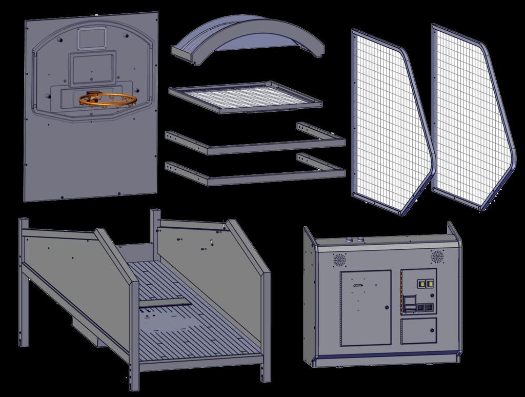

4 Fully Disassembled Games - Parts included Page PARTS PACKAGE


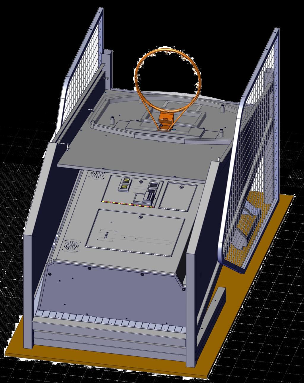
5 Place two basket balls under the main cabinet. Insert one 6110 insert to one side and one 6110 with 6107 attached to the other side in the middle hole, at the top of one leg (either, they are the same). When tightened a small space will be present between the leg and 6110 nuts. Repeat for other side. Then slide the front leg into the cabinet front until it rests on the AA06110 inserts. Secure using one 6110 insert to one side and one 6110 with 6107 attached to the other side in the upper hole. Repeat for the other side. REPEAT for the back leg using the same hardware and hole positions Space ** NOTE ** * Both legs are same size * REPEAT FOR BACK LEGS Both sides


6 Lift the cabinet back upright. Then position the backboard at the back of the cabinet. Use two 6799 Allen bolts to secure the backboard to the cabinet Then connect the two backboard harnesses into the cabinet base.


7 Lift the left side cage up onto the cabinet. It mounts to the inside of the cabinet. Using four AA6220 bolts secure the back of the cage to the backboard. AA6220 Then using three AA6110 insert on the inside and three AA6444 bolts on the outside, secure the bottom of the left cage to the cabinet base AA6444 REPEAT FOR THE RIGHT CAGE


8 Slide the basket ball deflector cage in between the side cages and cabinet base. The bracket goes at the top of the deflector. Attach the deflector cage with four AA6281 bolts from the top, two on each side. Secure with four AA6966 nylon nuts from the bottom, two on each side. Bracket at bottom even though the picture shows it at top. AA6281 AA6966


9 Lift the top cage up onto the cabinet. Using four AA6211 bolts secure the sides of the top cage to the cage sides. AA6211 Attach the podium to the front of the cabinet using four 6369 bolts and AA6212 washers AA6212


10 Connect the cabinet base harnesses to the podium harness. There are three in total. Connect the AC power cord behind the podium. Toggle the AC power button to the I position. The game will power on, run a quick power on test, and go into attract mode. Your game is now fully assembled.
. Continue to connect cabinets this way until you get to the last cabinet.")


11 LINKING To link two or more games together, connect one end of a RJ45 linking cable to the OUT (J5) jack of the first cabinet. Then connect the other end into the next game at IN (J4). Continue to connect cabinets this way until you get to the last cabinet. This cabinet you would connect a cable from the out (J5) to the TERM (J9) connector of the last cabinet. No software options need to be changed in order to enable linking! TERM Game 3 Game 2 Game 1 OUT IN OUT IN OUT When power is applied, the game will display its version number on the back board, then pause, show it s assigned ID, then go into attract mode. If the game shows dashes instead of a assigned ID number, there was failed communication between the games. Double check connections go in to out and term is installed in last game. NEVER MOVE GAMES WITH LINK CORD ATTACHED!


12 Mega Marquee Two Game Install To install a Mega Marquee onto two games attach one NS1031 support bracket to the left game with two AA6094 hex bolts, two AA6212 washers, and two NS3004 spacers. Then attach another NS1031 support bracket on the right game with two AA6094 hex bolts, two AA6212 washers, and two NS3004 spacers.


13 Mega Marquee Three Game Install To install a Mega Marquee onto three games attach one NS1031 support bracket to the center game with two AA6094 hex bolts, two AA6212 washers, and two NS3004 spacers. Then attach another NS1031 support bracket on the same game with two AA6094 hex bolts, two AA6212 washers, and two NS3004 spacers.


14 STOP! Do not attempt to lift the marquee up on the support brackets without sufficient help. We recommend at least one additional person to lift the marquee up onto the support brackets. Secure the Mega Marquee with two AA6917 Allen bolts, four AA6212 washers and two PC60604 nylon nuts. The Then attach another NS1031 support bracket on the right game with two AA6624 hex bolts and two AA6212 washers. Then at the back use one AA6624 hex bolt and AA6212 washer at the top hole. The bottom hole use AA6917 and AA6212. REPEAT FOR THE OTHER BRACKET.
15 Marquee Linking To link the marquee to two or more games, connect one end of a RJ45 linking cable to the IN (J4) jack of the first cabinet (GAME 1). Then connect the other end into the IN of the marquee. TERM Game 2 Game 1 OUT IN OUT IN When power is applied, the game will display its version number on the back board, then pause, show it s assigned ID, then go into attract mode. If the game shows dashes instead of a assigned ID number, there was failed communication between the games. Double check connections go in to out and term is installed in last game. The Marquee will display dashes when there is no communication. NEVER MOVE GAMES WITH LINK CORDS ATTACHED!
 shows you option number while the left display (HIGH SCORE) shows you the value for that option.")
16 Programming Options Game options can be changed in program mode. The game must be in attract mode (no one playing the game) to enter program mode. Open the coin door to access the program button. Press the program button to enter program mode. The right display (SCORE) shows you option number while the left display (HIGH SCORE) shows you the value for that option. Pressing the SELECT button advances to the next option while pressing UP or DOWN buttons will change the value for that option. The next page details the options available and their meanings. NOTE: THIS IS A ONE PLAYER GAME ONLY. VALUE OPTION PROGRAM SELECT UP DOWN
17 Version 1.02 Option Default Min Max Inc 0 Game Volume Game Volume This option adjusts the volume levels for game commentaries and announcements. 1 Background Volume Background Volume This option adjusts the volume of ambient noises and music. 2 Coin Cost of Credit Defines how many pulses are needed to give one credit to start a game. A pulse can come from either the coin switch or dollar bill validator. 3 Coin # of Coin 1 s Coin line 2 wire is worth X many pulses of coin 1 pulses. For example a dollar coin is worth 4 quarters. If you attached a quarter to coin 1 wire and a dollar mech to coin 2 wire you would set this option to 4 because a dollar is worth four quarters (pulses). 4 DBV # of Coin 1 s DBV line is worth X many pulses of coin 1 pulse. Your DBV can be set in two ways. If the DBV is set to 4 then this option is set to 1. If your DBV is set to 1 then this option is set to 4. 5 Discount # of Games til Disc When a value is other than 0 that many games purchased in a row (before starting a game) will result in one free game. 6 Games Per Credit # of Games Added per Credit This option allows you to give more than one game per credit. For examples if this option is set to 2 and a player has purchased one credited, the game will give the player two games for that one credit. 7 Game Time Game in Seconds The value of this option determines the total game time. 8 Attract Time Attract time How many minutes should the attract mode should run. The type is set in option 7. 9 Attract Type Hoop Move 0/2, Audio 0/1 A value of 0 = no attract mode, 1 = audio only, 2 = backboard movement only, and 3 means both audio and backboard movement. 10 Ticket Divider Ticket Divider (Points/Divider) This value is divided into the total amount of points earned to determine the amount of tickets to be paid. For example a value of 5 and the play scored 100 points at the end of the game, the game would pay 20 tickets out (if option 16 is set to 1).
18 11 JFP Just for Playing Tickets A value set here will pay this amount of tickets no matter how many points scored. 12 Hoop Motion Game Hoop Motion On = 1 Off = 0 This option will disable the back board from moving. 13 Link Time How long to Wait for Link time This option allows you to wait for this amount of time for other players to coin in before starting a game. (for linked games only). 14 High Score Ticket Bonus Bonus Tickets This option sets how many tickets will be paid out if the high score is achieved. This is in addition to points scored. 15 Default High Score Default High Score/ Not saved This option sets the high score on power up. 16 Save High Score = Save, 0 = No Save This option tells the game to remember the high score or not. 17 Ticket Cap Max Tickets Given per game, 0 = off This option will limit the total amount of tickets that can be paid. 18 Ticket Multiplier JFF/Free, 1-Normal, 2-1/2 physical This option allows you to turn off tickets or divide the amount of tickets owned in half. Leaving the value on 1 will pay out 1 ticket owed = 1 ticket paid. When set to 1 or 2 options 11 and 17 are used. When both 18 and 11 are 0 and 17 is 1 the game will give a free game instead of tickets. If 18 and 17 are 0 but 11 has a value, those tickets will be paid no matter what the player scores. If 18,11, and 17 are 0 then the game is in just for fun mode and no tickets will be paid Point Time Point time left start time This option sets the length of time the game will award 3 points instead of 2 at the end of the game. It will not add additional time to the game play. 20 Bonus Round Time Bonus Round Length This value sets the length of time for the bonus round. This is in addition to the game time. The player must score at least the value stored in option 19 to be able to play the bonus round. 21 Bonus Round Target Target Score for Bonus Round This is the amount of points needed to play the bonus round at the end of the game. Note, if games are linked, each player will be allowed to play the bonus round regardless of points won if one player achieves the score. 22 Bonus Round Points Points per Basket Bonus Round This option allows you to set the amount of points for each basket during the bonus round.
19 23 Hoop Motion Bonus Hoop Motion On = 1 Off = 0 You can enable or disable the backboard from moving during the bonus round. This will not change the settings for game play or attract motion. 24 Color Attract Color 1 This option is for color 1 of the attract colors the game will cycle through during attract mode. 25 Color Attract Color 2 This option is for color 2 of the attract colors the game will cycle through during attract mode. 26 Color Attract Color 3 This option is for color 3 of the attract colors the game will cycle through during attract mode. 27 Factory Reset Factory Reset A setting of 1 will reset and load all default values to the game. Ticket out options: Options that need to be set: Normal Tickets 18 = 1, 11 and 17 used ½ Tickets 18 = 2, 11 and 17 used Just For Fun 18 = 0, 11 = 0, 17 = 0 Set Tickets 18 = 0, 11 = Tickets, 17 = 0 Free Game on High Score 18 = 0, 11 = 0, 17 = 1 Color codes Color 0 Red Color 1 White Color 2 Blue Color 3 Orange Color 4 Green Color 5 Yellow Color 6 Pink Color 7 Purple Keeping the game balls slightly soft, will ensure more control, and better gameplay!
20 Programming Options for Mega Marquee 1.01 Option Default Min Max Inc 0 Score Base Lowest Score 1 Ticket Base Tickets for High Score 2 Games To Dec How many Lost games to Dec Score 3 Dec Amount When Dec change by this amount 4 Games to Inc Tickets Game losses to Inc Tickets 5 Inc Amount How many Tickets when Inc d 6 Save High Score High Score remains for power cycle 7 Color Color 1 8 Color Color 2 9 Color Color 3 10 Color Speed Speed of Color Cycle Selected Color Numbers Color 0 Red Color 1 White Color 2 Blue Color 3 Orange Color 4 Green Color 5 Yellow Color 6 Pink Color 7 Purple Note: To enter programming mode you must be on linked game #1. Press the Down button to enter programming mode. You cannot be in game programming mode to do this. After that the Marquee will show a P0 and a value. That is option #0. Pressing the select button will cycle thru the modes. Pressing the up button will increment the option wrapping if you go to far. Pressing the down button will decrement the option, again wrapping if you go to low. To exit Marquee programming press the prog button. Doing this once will exit programming of the marquee and pressing it again will enter programming for the game.
21 Trouble Shooting : Linking Your Games It is important to set each game option the same between games. Setting games to different settings would confuse the players when they are competing head to head. Players would win different amounts of tickets at different scores or be charged differently to play games. When a marquee is used, the marquee will show the points needed to score and the amount of bonus tickets that can be win. If all games are set differently, the marquee will use the highest settings for those two options out of all the linked games. When the games are powered on they will first display the version number of the software installed and preform a self check. Then they will determine what station ID they are. This is displayed then as ID and then a number. The game will continue to show dashes until it has determined what station ID it is. A setting in the software will determine how long to wait before going into game mode. This occurs if no communication is found. This setting can be increased if more games are linked together requiring more time for them to communicate. NOTE: THIS IS A ONE PLAYER GAME ONLY.
22 LINKING If the games do not ID themselves at startup you will need to isolate the problem to either one of the display boards or one of the cables. It is recommended to isolate the games to pairs when working with three or more games. In this example below, it is recommended to unplug the connector going in to game 3 and move it to TERM of game 2. Reboot the game. If it correctly configures the ID then move the back board display of game 3 to game 2 to retest. At this point if the game no longer will correctly configure, replace the back board display. If it never configured correctly replace the cable from game 1 out to game 2 in with another cable. Although the cables are standard and can be tested with a cable tester the connection between games are not standard and contain harmful voltages. They are designed only for use with ICE products. Once you have two games linked and working, test the remaining cables between the out of game 1 and the in of game 2. TERM Game 3 Game 2 Game 1 OUT IN OUT IN OUT
23 Marquee Linking When the marquee is powered on it will display dashes until the it can communicate with other linked games. At anytime the communication is lost the display will show dashes. If the marquee power is applied after the games are powered on, the marquee will not establish communication with other games. Always power the marquee on first or at least at the same time with the games. Powering games on first will result in the marquee not linking. The marquee can only be plugged in before Station ID 1 game or the game that has no input from another game plugged in. The marquee is always the first game in the chain. If the marquee cannot establish any communication with other games start by replacing the link cable. Then check to see if the last game has the OUT connected to TERM of the same game. Unplug the marquee and power on games. Do the games assign themselves station ID s? If yes and you have replaced the cable then replace the marquee board. TERM Game 2 Game 1 OUT IN OUT IN


24 Score sensor theory of operation The game uses an intelligent reflective sensor to register a score during the game. The sensor operates by transmitting a beam of light from the transmitter LED and then looks for the beam to be bounced back at the receiving LED. Both of these LEDs are intergraded into a single sensor assembly. The light that is transmitted from the sensor is red and it can bee seen with the naked eye when a white piece of paper is held in front of the sensor assembly. N/C Net sensor troubleshooting If shots do not register Check for +12 VDC power to the net sensor, this can be done visually or with a voltage meter. A red LED facing the customer and a green LED on the lower left side are visual indicators the sensor has power. To use a voltage meter, at the back of the sensor attach the red probe on the Brown wire (12 VDC) and the black probe to light blue/blue wire (ground). The meter should read 12 VDC or within 10 percent of that. - If no voltage is present then move the red probe to pin 1 and the black probe to pin 3 at connector J 1 of the score display board. - If there still is no voltage and the display is lit then replace the display board. - If there is power present at J1 connector then check / repair the harness Check the signal line of the net sensor. There is a LED visual indicator on the left side of the net sensor that will light orange when the sensor is blocked. You can measure the signal line output to the score display by touching the red probe on the black wire (signal) and the black probe on the light blue/blue wire (ground) at the sensor. The meter should read voltage at 3.3VDC and when blocked, 0 VDC. - if the voltage does not change, with the probes previously attached, adjust the sensitivity of the net sensor. If adjusting the sensitivity still doesn t show voltage, replace the sensor. - if the voltage is changing and the score display is on, check and repair the harnessing from the sensor to J1 at the back board. - If no problems are found with the wiring then replace the display board. Net sensor adjustment The net sensor has a sensitivity adjustment located on the side, below the visual indicator LEDS, to adjust for environmental conditions in your location. Turning the screw clockwise will increase the sensitivity and turning it counter clockwise will decrease the sensitivity.


25 Back board motor theory of operation The game uses a motor to move the hoop assembly left and right. A motor arm connects to the motor and rests between two DELRIN blocks that ride on a HPDE channel. The motor will always attempt to keep itself centered. This is accomplished by using an optical sensor to read reflective tape at the back of the motor arm. This determines when it is in the center position. If the sensor board does not see the reflection from the tape, it will activate the motor periodically throughout the game. The motor is activated when the display board sends a low voltage signal to a sold state relay. This relay connects to the motor and controls the incoming A.C. voltage to the motor. When the motor drive signal is present at the relay its internal contacts completes the AC circuit to the motor causing the motor to move the hoop assembly. WARNING when servicing the backboard assembly keep your fingers clear of the motor arm to avoid injury! Troubleshooting the back board not moving. Step 1 - Check option 12 is set to 1. This enables movement. Step 2 - Check the set screw in the motor arm is tight and engaging the shaft. Step 3 - Check for incoming AC voltage between tabs 1 and 2 (brown wires) of the solid state relay. -if there is voltage then proceed to the next step. -If there is no voltage then inspect the harnessing and all AC inter connections. Step 4 - check for the signal to turn the relay on. There is an indicator LED on the solid state relay which lights when the signal is present. You can measure this signal using a voltage meter set to DC voltage. Place the red probe on pin 3 (orange/blue trace wire) and the black probe on pin 4 (violet wire). The meter should read 0 VDC when there is no signal. It should change to 12 VDC with a signal present. There will always be a constant 12 VDC on tab 3 of the relay if you use on the back display board at J2, pin 2. If the 12 VDC is not present at this pin, check the voltage at the connector J6, pin 1 on the same board. - if there is a signal to the relay and the voltage to the motor is present then replace the motor. - if no signal is present at the relay measure at connector J6 with the red probe on pin 5 and the black probe on pin 1. - if 12 VDC is present repair the harnessing. - if there is o VDC replace the back display board.

26 Hoop will not center. The optical encoder mounted on the rear of the back board assembly reads the reflective tape on the back of the motor arm to determine when the hoop is in the center position. When the hoop is centered it is called the home position of the motor. The back display board will always try to move the hoop to the center position even if the movement is disabled in the software programming. Step 1 - inspect the optic sensor for signs of physical damage and that the reflective tape on the motor arm is still present and undamaged. Step 2 - measure the optic board with the red probe on pin 1 (+12vdc, orange wire) and the black probe on pin 3 (ground, black wire). You should measure +12 VDC. - if you have the correct voltage, proceed to step 3. - inspect the wiring for damage all the way back to connector J6 on the timer board. If the wiring is good and the display is off, replace the display. Step 3 - measure at the optic the output (signal) by placing the red probe on pin 2 (signal, white wire) and the black probe on pin 3 (ground, black wire). You should see +5 VDC when the reflector tape is in front of the optic. 0 VDC when it is not. - If not working in this manner inspect the harnessing and connections to the display board to connector J6. Unplug the connector and measure with the red probe pin 3 and the black probe on pin 4. - if the voltage is 3.3vdc then replace the sensor. - if not then replace the display board. Position sensor Motor Drive
27 Ball gate theory of operation The game uses a linear actuator to control the ball gate. The linear actuator has a spring loaded mount that pushes the gate back up if it is pressed down. There are internal limit switches to control the movement of the push rod when it reaches the end of its travel in the actuator. For this reason, there will always be voltage to the actuator. The reason for this is so the gate will remain closed until otherwise told to do so. When the game is started, the main board will send a signal to a relay board located at the front of the cabinet of game. This will reverse the polarity of the voltage to the actuator causing the gate to open. No movement from the ball gate Step 1 - inspect the wiring and connections from the actuator to the relay board for signs of damage. This is located inside the front podium. Step 2 - check the 12 VDC input voltage to the relay PCB at connector J1 by touching the red probe on pin 1 (orange wire ) and the black probe on pin 2 (black wire). You should measure +12 VDC. - if no voltage is present check the wires and connections back to J3 connector of the main board. Step 3 - Start a game and measure the voltage at J1 again but use pin 3 (brown/yellow wire) for the red probe and pin 2 for the black probe. - If no voltage is present and all harnessing and connectors are good, replace the main board if missing. Step 3 - check for output voltage on the J2 connector of the relay PCB. In standby mode you will see +12vdc from the black wire (positive, use red probe) to white wire (negative, use black probe). When the game is started the voltage will reverse polarity. -if no voltage is present, replace the relay PCB. -if voltage is present and the wiring is good to the actuator, then replace the actuator. 12 GN Sig-
28
29
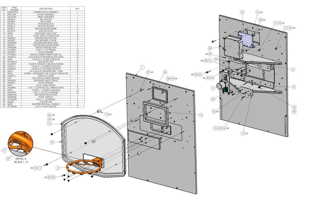
30
31
32
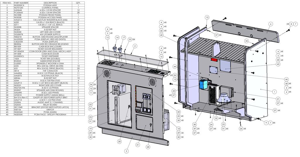
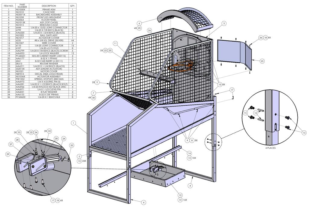
33 Suggested Spares NS3050X ASY FRONT CABINET Item number Description AA5014 LOCK (7/8 CAMLOCK),45 BA2063LX HARNESS (MONITOR SUPPLY AC) BUTTON MED RD ORANGE BB LEG- BB2004 END CB2233X PCBA (DISPLAY) DJ2007 SPEAKER 6" WOOFER 4 OHM E02007 SPEAKER (4/8 OHM ROUND) E2034XX PCBA (BRAIN BOARD W/ 8716 FLAS GF2010 POWER SUPPLY +12VDC 29A (ROHS) ML2032X PCBA (DISPLAY) RED LED DIGITS NB2218 BUTTON MED ROUND (MULTIPLAYER NS2007X ASY (POWER MOD 6 AMP) NS2033X PCBA FACE NS2034X PCBA MAIN NS2050HX HARNESS (MAIN) HARNESS (PROGRAMMING BUT- NS2051LX TONS) NS2064LX HARNESS (AMP POWER 12V) NS2084LX HARNESS (AUDIO) ZS2006 AUDIO AMP 2.1 CHANNEL ZS2035X PCBA (RELAY) NS1072X ASY (MOTOR MOUNT) Item number Description E02111 RELAY SOLID STATE (SVDA/3V10) NS1077 DRIVE ROD NS2008A GEARBOX NS2061LX HARNESS (AC RELAY) NS2063LX HARNESS (HOOP SENSOR DC POWER) NS7048 REFLECTOR PE2009SX ASY (MOTOR 110V) SPG WS2039NSX HPCB (HOOP SENSOR) NS3064X ASY REAR CABINET Item number Description E00210NSX HARNESS (HOOP SENSOR) E00724NSAX ASY (LED STRIP LARGE RGB 52 CUTS E00724NSBX ASY (LED STRIP LARGE RGB 21 CUTS MD1239-P200 HOOP (ORANGE) NB3001P BASKETBALL 8.5" (HARDENED PU L NB3025 BACKBOARD STANDOFF (REV A) NS1072X ASY (MOTOR MOUNT) NS2032X NS3070 NS7048 PW1052 NS1013X Item number E00788NSAX PCBA DISPLAY BACKBOARD REFLECTOR SPRING, STOP(27) (BW HAN BUMPER (SMALL ROUND WITH IN- NER SC4002 SF3008 CHAIN NET ZS2015X ASY (LINEAR ACTUATOR) ASY (TOP CAGE) Description ASY (LED STRIP LARGE WHITE DUAL Item number Description LC3002 FILTER (2 x 2-1/2 RED) ML3001 DISPLAY FILTER SCORE (CONTROL NB3009 FILTER DISPLAY Rev.1 MISC Items Item number Description NS2008A Gearbox only NB3002P Leather balls NS1077 Hoop Drive Arm

34 WARRANTY POLICY I.C.E. Inc warrants all components in new machines to be free of defects in materials and workmanship for the period listed below: 180 days on Main PCB s, Computers & Motors 1 year on all LCD monitor panels 90 days on all other electronic and mechanical components 30 days on all I.C.E. repairs and parts purchases I.C.E. Inc shall not be obligated to furnish a warranty request under the following conditions: Equipment or parts have failed through normal wear and tear Equipment has been subjected to unwarranted stress, abuse or neglect Equipment has been damaged as a result of arbitrary repair/modification Products will only be covered under warranty by obtaining an I.C.E. authorized RMA #. To obtain an RMA # please provide I.C.E. tech support with the game serial # or original I.C.E. invoice # and a detailed description of the failure or fault symptoms. I.C.E. Inc will assume no liability whatsoever for costs associated with labor or travel time to replace defective parts. All defective warranty covered components will be replaced with new or factory refurbished components equal to OEM specifications. I.C.E. Inc will cover domestic UPS ground, or comparable shipping costs during the warranty period. International or expedited shipments are available for an additional charge. To obtain credit defective parts must be returned to I.C.E. Inc, at the customer s expense, within 30 days. After 30 days a 15% re-stocking fee will apply to all returns. ICE distributors are independent, privately owned and operated. In their judgment, they may sell parts and/or accessories other than those manufactured by I.C.E. Inc. We cannot be responsible for the quality, suitability or safety of any non-i.c.e. part or modification (including labor) that is performed by such a distributor. Innovative Concepts in Entertainment Main St. Clarence, NY Phone #: (716) Fax #: (716)
Service Manual Innovative Concepts in Entertainment
 Service Manual Innovative Concepts in Entertainment 10123 Main Street Clarence, New York 14031 (716) 759-0360 www.icegame.com Table of Contents What s included 3 Safety and Warnings 4 Game Assembly 5-9
TABLE OF CONTENTS TABLE OF CONTENTS
 NBA Jr. Basket Ball OWNERS AND SERVICE MANUAL INNOVATIVE CONCEPTS IN ENTERTAINMENT INC. 0 MAIN STREET, CLARENCE, NY 0 SERVICE: -7-79-00 FAX: -7-79-088 E-MAIL: service@icegame.com WEBSITE: www.icegame.com
OWNERS AND SERVICE MANUAL 2001 INNOVATIVE CONCEPTS IN ENTERTAINMENT INC.
 OWNERS AND SERVICE MANUAL 2001 INNOVATIVE CONCEPTS IN ENTERTAINMENT INC. 10123 MAIN STREET, CLARENCE, NEW YORK 14031 SERVICE 716-759-0360 SALES 716-759-0370 FAX 716-759-0390 E MAIL play@icegame.com TABLE
OWNERS AND SERVICE MANUAL INNOVATIVE CONCEPTS IN ENTERTAINMENT INC MAIN STREET, CLARENCE, NY SERVICE: FAX:
 OWNERS AND SERVICE MANUAL INNOVATIVE CONCEPTS IN ENTERTAINMENT INC. 10123 MAIN STREET, CLARENCE, NY 14031 SERVICE: 1-716-759-0360 FAX: 1-716-759-0884 E-MAIL: service@icegame.com WEBSITE: www.icegame.com
SHIRTS AND SKINS JUNIOR EDITION COASTAL AMUSEMENTS INC SWARTHMORE AVE LAKEWOOD, NJ TEL: FAX:
 SHIRTS AND SKINS JUNIOR EDITION COASTAL AMUSEMENTS INC. 1935 SWARTHMORE AVE LAKEWOOD, NJ 08701 TEL: 732-905-6662 FAX: 732-905-6815 W632 SHIRTS AND SKINS FUSE AT MAIN BOARDS F1, 20 mm 2A GATE MOTOR; F2,
SURE SHOT DUAL ELECTRONIC BASKETBALL GAME ASSEMBLY INSTRUCTIONS
 SURE SHOT DUAL ELECTRONIC BASKETBALL GAME ASSEMBLY INSTRUCTIONS NG33BL THANK YOU! Thank you for purchasing this product. We work around the clock and around the globe to ensure that our products maintain
ASPEN OUTDOOR TABLE TENNIS
 ASPEN OUTDOOR TABLE TENNIS Replacement Parts Order direct at or call our Customer Service department at (800) 225-7593 8 am to :30 pm Central Standard Time January 201 UPC Code 7-19265-51830-3 Staple your
Super Shot Deluxe Assembly and Operating Manual
 SPECIFICATIONS... 3 INTRODUCTION... 4 WARNINGS... 4 ASSEMBLY INSTRUCTIONS... 5 MAJOR GAME COMPONENT DEFINITIONS... 5 PRE-ASSEMBLY... 7 ASSEMBLY... 9 TESTING... 11 COIN TEST:... 11 TICKET TEST:... 12 SENSOR
PLEASE NOTE: Version LAI Games
 Version 1.4.2 PLEASE NOTE: Read this manual BEFORE operating the machine. Keep this manual for your reference. Go to www.laigames.com Click on Support to register your Game and receive future updates.
To Purchase This Item, Visit BMI Gaming (800)
") OWNERS AND SERVICE MANUAL INNOVATIVE CONCEPTS IN ENTERTAINMENT INC. 10123 MAIN STREET, CLARENCE, NY 14031 SERVICE: 1-716-759-0360 FAX: 1-716-759-0884 E-MAIL: service@icegame.com WEBSITE: www.icegame.com
OWNERS AND SERVICE MANUAL INNOVATIVE CONCEPTS IN ENTERTAINMENT INC. 10123 MAIN STREET, CLARENCE, NY 14031 SERVICE: 1-716-759-0360 FAX: 1-716-759-0884 E-MAIL: service@icegame.com WEBSITE: www.icegame.com
PLEASE READ ALL INSTRUCTIONS BEFORE OPERATING THIS MACHINE
 PLEASE READ ALL INSTRUCTIONS BEFORE OPERATING THIS MACHINE TRIGGER HAPPY IS AN EXCITING NEW SHOOTING GALLERY GUN GAME FROM FUN INDUSTRIES. THIS MACHINE IS DESIGNED TO DISPENSE 2 PRIZES AS WELL AS TICKET
OWNERS AND SERVICE MANUAL INNOVATIVE CONCEPTS IN ENTERTAINMENT INC MAIN STREET, CLARENCE, NY SERVICE: FAX:
 OWNERS AND SERVICE MANUAL INNOVATIVE CONCEPTS IN ENTERTAINMENT INC. 10123 MAIN STREET, CLARENCE, NY 14031 SERVICE: 1-716-759-0360 FAX: 1-716-759-0884 E-MAIL: service@icegame.com WEBSITE: www.icegame.com
ABOUT SMOKIN' TOKEN EXTREME
 ABOUT SMOKIN' TOKEN EXTREME Operators distinguish Smokin Token as one of the great redemption success stories, and are now able to share in that unprecedented success for yet another generation. Smokin
To Purchase This Item, Visit BMI Gaming (800)
") OWNERS AND SERVICE MANUAL INNOVATIVE CONCEPTS IN ENTERTAINMENT INC. 10123 MAIN STREET, CLARENCE, NY 14031 SERVICE: 1-716-759-0360 FAX: 1-716-759-0884 E-MAIL: service@icegame.com WEBSITE: www.icegame.com
OWNERS AND SERVICE MANUAL INNOVATIVE CONCEPTS IN ENTERTAINMENT INC. 10123 MAIN STREET, CLARENCE, NY 14031 SERVICE: 1-716-759-0360 FAX: 1-716-759-0884 E-MAIL: service@icegame.com WEBSITE: www.icegame.com
MEC Auto-Mate Assembly Manual. For MEC 9000G/GN and 8567 Grabber Series
 MEC Auto-Mate Assembly Manual For MEC 9000G/GN and 8567 Grabber Series Thank you We really appreciate your support of our product line. But our commitment to you hardly ends here. We won't be satisfied
OWNERS AND SERVICE MANUAL INNOVATIVE CONCEPTS IN ENTERTAINMENT INC MAIN STREET, CLARENCE, NY SERVICE: FAX:
 OWNERS AND SERVICE MANUAL INNOVATIVE CONCEPTS IN ENTERTAINMENT INC. 10123 MAIN STREET, CLARENCE, NY 14031 SERVICE: 1-716-759-0360 FAX: 1-716-759-0884 E-MAIL: service@icegame.com WEBSITE: www.icegame.com
COASTAL AMUSEMENTS, INC, 1950 SWARTHMORE AVE LAKEWOOD, NJ (732)
") OPERATOR S MANUAL Version 1.1 COASTAL AMUSEMENTS, INC, 1950 SWARTHMORE AVE LAKEWOOD, NJ 08701 (732) 905-6662 http://www.coastalamusements.com INTRODUCTION Temple Run 2 is an amusement redemption game in
OPERATOR S MANUAL Version 1.1 COASTAL AMUSEMENTS, INC, 1950 SWARTHMORE AVE LAKEWOOD, NJ 08701 (732) 905-6662 http://www.coastalamusements.com INTRODUCTION Temple Run 2 is an amusement redemption game in
MZ2 HEADPHONE AMPLIFIER, PREAMP, & STEREO AMPLIFIER USER GUIDE
 MZ2 HEADPHONE AMPLIFIER, PREAMP, & STEREO AMPLIFIER USER GUIDE Linear Tube Audio Takoma Park, MD, USA WARNING: For safety, the cover of this amplifier should be secured at all times. DC voltages as high
WEL-200 O P E R A T I N G I N S T R U C T I O N S W I R E L E S S E D G E L I N K
 O P E R A T I N G I N S T R U C T I O N S WEL-200 TM W I R E L E S S E D G E L I N K 4564 Johnston Parkway, Cleveland, Ohio 44128 P. 800 426 9912 F. 216 518 9884 Sales Inquiries: salessupport@emxinc.com
PROGRESSIVE JACKPOT MARQUEE
 PROGRESSIVE JACKPOT MARQUEE 1 FACTORY CONTACT INFORMATION BAY TEK GAMES INC. Pulaski Industrial Park 1077 East. Glenbrook Drive Pulaski, WI 54162 USA JOIN OUR SERVICE FIRST NETWORK! This free service is
TIRADE MMXI SOCCER TABLE
 TIRADE MMXI SOCCER TABLE Replacement Parts Order direct at or call our Customer Service department at (800) 225-7593 8 am to 4:30 pm Central Standard Time Publication 64-0908 Rev D August 2014 UPC Code
NEO CAR AUDIO. Neo AUXiN AUX INPUT INTERFACE. Instruction Manual
 NEO CAR AUDIO Neo AUXiN AUX INPUT INTERFACE Instruction Manual IMPORTANT NOTE Neo AUXiN Dip switch positions MUST be set BEFORE any other step is taken. Otherwise, the kit will not operate properly. See
Tauten Tab Tension Screen User Manual
 Tauten Tab Tension Screen User Manual Thank you for choosing a Tauten Series Tab Tension screen by Cirrus Screens. Please read through this user manual and understand all instructions before installing
OPERATOR S MANUAL Model 58B Prefeed / Dereeler
 110 Fairgrounds Drive P.O. Box 188 Manlius, NY 13104-0188 USA 315.682.9176 FAX: 315.682.9160 OPERATOR S MANUAL Model 58B Prefeed / Dereeler PRODUCTION WIRE PROCESSING EQUIPMENT Website: www.carpentermfg.com
Shelti, Inc. 333 Morton Street Bay City, MI Phone Fax. Bayside Dollar Bill Acceptor Pool Table Manual & Instructions
 Shelti, Inc. 333 Morton Street Bay City, MI 48706 989-893-1739 Phone 989-893-1809 Fax Bayside Dollar Bill Acceptor Pool Table Manual & Instructions Contents Section-1 Introduction Bayside DBA Pool Table
PLEASE NOTE: Preliminary. LAI Games
 Preliminary PLEASE NOTE: Read this manual BEFORE operating the machine. Keep this manual for your reference. Go to www.laigames.com click on Support to register your games and receive of future updates.
CM3000. Operator s Manual. ChangeMaker. Seaga Manufacturing, Inc. 700 Seaga Drive Freeport, IL USA
 CM3000 ChangeMaker Operator s Manual Seaga Manufacturing, Inc. 700 Seaga Drive Freeport, IL USA 61032 www.seagamfg.com INTRODUCTION Congratulations on the purchase of your new ChangeMaker. This ChangeMaker
OWNERS AND SERVICE MANUAL INNOVATIVE CONCEPTS IN ENTERTAINMENT INC MAIN STREET, CLARENCE, NY SERVICE: FAX:
 OWNERS AND SERVICE MANUAL INNOVATIVE CONCEPTS IN ENTERTAINMENT INC. 10123 MAIN STREET, CLARENCE, NY 14031 SERVICE: 1-716-759-0360 FAX: 1-716-759-0884 E-MAIL: service@icegame.com WEBSITE: www.icegame.com
INSTALLATION INSTRUCTIONS
 INSTALLATION INSTRUCTIONS Compact Power Amplifier NORTH AMERICA 3130 East Miraloma Avenue Anaheim, CA 92806 USA USA and Canada Phone: 1.800.368.9700 Fax: 1.800.832.4888 Other Locations Phone: (001).714.632.7100
PORTABLE ADJUSTABLE BASKETBALL SYSTEM
 Instruction Manual PORTABLE ADJUSTABLE BASKETBALL SYSTEM P A R T S L I S T 5 1/2 and 8 safe play clearance Item Qty Description Item Qty Description A 1 Portable Base Assembly M 4 1/2 Lock Nut B 2 Front
OPERATION & SERVICE MANUAL FOR FC 110 AC POWER SOURCE
 OPERATION & SERVICE MANUAL FOR FC 100 SERIES AC POWER SOURCE FC 110 AC POWER SOURCE VERSION 1.3, April 2001. copyright reserved. DWG No. FC00001 TABLE OF CONTENTS CHAPTER 1 INTRODUCTION... 1 1.1 GENERAL...
Pushbutton Bollard. Wireless Control for BlinkerSign, RRFB or BlinkerBeacon User Guide. Blinker Division Solar LED Solutions
 Blinker Division Solar LED Solutions The Route To Safety, One Solution At A Time Pushbutton Bollard Wireless Control for BlinkerSign, RRFB or BlinkerBeacon User Guide TAPCO Traffic & Parking Control Company,
RPS /02 Effective for models with serial numbers beginning with "G".
 Instruction Sheet B2000 Cyclone Bender RPS-0097 0/02 Effective for models with serial numbers beginning with "G". IMPORTANT RECEIVING INSTRUCTIONS Visually inspect all components for shipping damage. If
COASTAL AMUSEMENTS, INC, 1950 SWARTHMORE AVE LAKEWOOD, NJ (732)
") OPERATOR S MANUAL COASTAL AMUSEMENTS, INC, 1950 SWARTHMORE AVE LAKEWOOD, NJ 08701 (732) 905-6662 http://www.coastalamusements.com INTRODUCTION Subway Surfers is an amusement redemption game in which the
OPERATOR S MANUAL COASTAL AMUSEMENTS, INC, 1950 SWARTHMORE AVE LAKEWOOD, NJ 08701 (732) 905-6662 http://www.coastalamusements.com INTRODUCTION Subway Surfers is an amusement redemption game in which the
LifeGear G1 /HOME GYM ITEM NO.: 63100
 LifeGear G1 /HOME GYM ITEM NO.: 63100 OWNER S MANUAL IMPORTANT: Read all instructions carefully before using this product. Retain this owner s manual for future reference. The specifications of this product
ELECRAFT Application Note
 ELECRAFT Application Note Front Panel Microphone Circuit Modification Revision A, November 12, 2008 Copyright 2008, Elecraft, Inc., All Rights Reserved Background Some K3 owners have noted distorted transmit
Dual Arm Tilt LCD Mount
 Installation Manual model # 51324 M o u n t i n g S y s t e m s Dual Arm Tilt LCD Mount Fits Displays 13 to 32 Supports Up to 50 lbs (23 kgs) Projection from Wall from 3 to 17 Meets VESA Standards 50/75/100,
PLEASE NOTE: LAI GAMES V 1.3
 V 1.3 PLEASE NOTE: Read this manual BEFORE operating the machine. Keep this manual for your reference. Go to www.laigames.com click on Operator Access to register your games and receive of future updates.
impact VC-500LR Monolight INSTRUCTIONS
 impact lighting equipment and accessories VC-500LR Monolight INSTRUCTIONS Congratulations on your purchase of the Impact VC-500LR Monolight. We feel that it will contribute much to your photographic skill
NewHeights Presidente Reception Assembly Instructions Warranty: raproducts.com/warranty
 NewHeights Presidente Reception Assembly Instructions Warranty: raproducts.com/warranty Failure to comply with or observe all assembly, safety, and operation instructions and warnings regarding use of
PLEASE NOTE: LAI GAMES V 3.1
 V 3.1 PLEASE NOTE: Read this manual BEFORE operating the machine. Keep this manual for your reference. Go to www.laigames.com click on Operator Access to register your games and receive of future updates.
WARRANTY. Long Range Systems, LLC, 20 Canal St, Suite 4N, Franklin, NH 03235
 WARRANTY Long Range Systems, Inc. warrants the trap release product against any defects that are due to faulty material or workmanship for a one-year period after the original date of consumer purchase.
8' HOT SHOT SKEEBALL TABLE ASSEMBLY INSTRUCTIONS
 8' HOT SHOT SKEEBALL TABLE ASSEMBLY INSTRUCTIONS NG2015 THANK YOU! Thank you for purchasing this product. We work around the clock and around the globe to ensure that our products maintain the highest
A-16D A-Net Distributor
 A-16D A-Net Distributor For use with the Personal Monitor Mixing System Information in this document is subject to change. All rights reserved. Copyright 2003 Aviom, Inc. Printed in USA Document Rev. 1.03
INSTRUCTION MANUAL LKG 601 Electrical Safety Analyzer
 INSTRUCTION MANUAL LKG 601 Electrical Safety Analyzer 110 Toledo Street Farmingdale, NY 11735 USA http://www.netech.org 510-USER-Manual Rev3 10/29/2007 Dear User, We appreciate your purchase of the LKG
Digi-Stop. Installation & Operation
 Digi-Stop Installation & Operation WARRANTY Accurate Technology, Inc. warrants the ProScale Systems against defective parts and workmanship for 1 year commencing from the date of original purchase. Upon
To Purchase This Game, Visit BMI Gaming Or Contact International Sales at (USA) The Simpsons Soccer
 The Simpsons Soccer") The Simpsons Soccer STANDARD OPERATING MANUAL Rev. 9-4-12 (Software Version: 07-30-12) Coastal Amusements, Inc. 1950 Swarthmore Ave. Lakewood, NJ 08701 +1 (732) 905-6662 sales@coastalamusements.com http://www.coastalamusements.com
The Simpsons Soccer STANDARD OPERATING MANUAL Rev. 9-4-12 (Software Version: 07-30-12) Coastal Amusements, Inc. 1950 Swarthmore Ave. Lakewood, NJ 08701 +1 (732) 905-6662 sales@coastalamusements.com http://www.coastalamusements.com
Installation & Operation Manual SAGA1-K Series Industrial Radio Remote Control
 Installation & Operation Manual SAGA1-K Series Industrial Radio Remote Control Gain Electronic Co. Ltd. Table Of Contents Safety Considerations ------------------------------------------------------------2
Operating Instructions and Parts Manual SLT-1100 Jumbo Scissor Lift Table
 Operating Instructions and Parts Manual SLT-1100 Jumbo Scissor Lift Table JET 427 New Sanford Road LaVergne, Tennessee 37086 Part No. M-140780 Ph.: 800-274-6848 Revision B1 05/2014 www.jettools.com Copyright
Puppy Jump Operations Manual
 Puppy Jump Operations Manual WARNING Be sure to read this Operation Manual before using your machine to ensure safe operation. 2013 Bob s Space Racers Incorporated 427 15 th Street, Daytona Beach, Florida
WRM-10 TM TRANSFORMER WINDING RESISTANCE METER
 WRM-10 TM TRANSFORMER WINDING RESISTANCE METER USER S MANUAL Vanguard Instruments Company, Inc. 1520 S. Hellman Ave. Ontario, California 91761, USA TEL: (909) 923-9390 FAX: (909) 923-9391 June 2009 Revision
Model 935A. Dual Tone Sender INSTRUCTION MANUAL
 Model 935A Dual Tone Sender INSTRUCTION MANUAL Monroe Electronics 100 Housel Ave Lyndonville NY 14098 800-821-6001 585-765-2254 fax 585-765-9330 monroe-electronics.com Printed in USA Copyright Monroe Electronics,
Operating Instructions and Parts Manual Folding Hydraulic Crane Model: JFHC-200X
 This Manual is Bookmarked Operating Instructions and Parts Manual Folding Hydraulic Crane Model: JFHC-200X WMH TOOL GROUP 2420 Vantage Drive Elgin, Illinois 60123 Part No. M-106206K Ph.: 800-274-6848 Revision
NewHeights Series 4 Bonita ET 3-Leg Workstation Warranty: raproducts.com/warranty
 NewHeights Series 4 Bonita T 3-Leg Workstation Warranty: raproducts.com/warranty Instruction #54022 Dated: 02/21/2019 1 of 12 RAD ALL INSTRUCTIONS BFOR USING THIS PRODUCT. WARNING US THIS PRODUCT ONLY
PULSE DISTRIBUTION AMPLIFIER OPERATING MANUAL
 SPECTRADYNAMICS, INC PD5-RM-B PULSE DISTRIBUTION AMPLIFIER OPERATING MANUAL SPECTRADYNAMICS, INC 1849 Cherry St. Unit 2. Louisville, CO 80027 Phone: (303) 665-1852 Fax: (303) 604-6088 www.spectradynamics.com
PLEASE NOTE: LAI Games
 PLEASE NOTE: Read this manual BEFORE operating the machine. Keep this manual for your reference. Go to www.laigames.com click on Operator Access to register your games and receive of future updates. LAI
Transmitter User Guide
 Transmitter User Guide Table of Contents Introduction...4 1 Getting Started...5 1.1 Overview... 5 1.2 Display... 6 1.3 Quick Start... 7 1.3.1 Setup... 7 1.3.2 Wake System... 7 1.3.3 Binding Receiver to
INSTALLATION AND MAINTENANCE MANUAL FOR GROUND MONITOR GM-250 COPYRIGHT 1983 AMERICAN MINE RESEARCH, INC.
 INSTALLATION AND MAINTENANCE MANUAL FOR GROUND MONITOR GM-250 COPYRIGHT 1983 AMERICAN MINE RESEARCH, INC. MANUAL PART NUMBER 180-0036 ORIGINAL: 1-17-83 REVISION: B (8-26-86) NOT TO BE CHANGED WITHOUT MSHA
LAI GAMES 2004
 www.laigames.com 1st Ed. SKILL July 2004 READ THIS MANUAL BEFORE OPERATING THE MACHINE. KEEP THIS MANUAL FOR YOUR REFERENCE. LAI GAMES Correspondence regarding this machine should be addressed to your
SOCCERMANIA User manual
 User manual Contents General information - Introduction Page 3 General information - Safety Page 3 Waranty terms Page 4 Machine description Pages 5-6 Main Board description Pages 7-9 MP3 instalation Page
DRIVEWAY SERIES D554 D560
 DRIVEWAY SERIES D554 D560 Version ' Keep this instruction manual in case you have to contact the manufacturer for replacement parts. 2 FAILURE TO FOLLOW THESE WARNINGS MAY RESULT IN SERIOUS INJURY AND/OR
00108/00110 INSTRUCTION MANUAL
 00108/00110 INSTRUCTION MANUAL Removable and Adjustable Mudflap System IMPORTANT! Please Read this Instruction Booklet prior to assembly of your Rock Tamer Kit. IMPORTANT! Exhaust Systems Note: Any modifications
Manual Carton Closing Staplers
 Operator s Manual Manual Carton Closing Staplers SHB00-A Item No. 6400 -/8" Crown Carton Closing Stapler 5/8" and /4" (5mm and 8mm) Ask for Genuine INTERCHANGE A58 and A4 Staples SHB50-C Item No. 640 -/4"
(2) Plastic Plugs (2) Frame Bracket. Spacers. License Plate Bracket. (2) 12mm Single Bolt Plates. (2) 12mm Double Bolt Plates
 Plastic Plugs (2) Frame Bracket. Spacers. License Plate Bracket. (2) 12mm Single Bolt Plates. (2) 12mm Double Bolt Plates") LDB-CSIL26-FB PARTS LIST: 1 LD1 Bumper Assembly 10 12mm Hex Nuts 1 Driver/left Frame Mounting 6 10-1.5mm x 35mm Hex Bolts 1 Passenger/right Frame Mounting 12 10mm x 27mm OD x 3mm Flat Washers 2 Spacers
LDB-CSIL26-FB PARTS LIST: 1 LD1 Bumper Assembly 10 12mm Hex Nuts 1 Driver/left Frame Mounting 6 10-1.5mm x 35mm Hex Bolts 1 Passenger/right Frame Mounting 12 10mm x 27mm OD x 3mm Flat Washers 2 Spacers
Com-Trol ADV-6000 Trouble Shooting Guide Click on red text to go to that page in guide
 Com-Trol ADV-6000 Trouble Shooting Guide Click on red text to go to that page in guide Topic Introduction 1 Tool Requirements 1 Trouble Shooting Check List 1 Page(s) Lost communications to controller(s)
PHG-1000X. Owner s Manual HOME GYM
 HOME GYM Owner s Manual WWW.BODYSOLID.COM THERE IS A RISK ASSUMED BY INDIVIDUALS WHO USE THIS TYPE OF EQUIPMENT. TO MINIMIZE RISK, YOU MUST FOLLOW THESE RULES:! " # $ % & ' ( ) * + ' (, ' " -. *, * ) )
Big Bang. B B O w n e r s M a n u a l. Power Amplifiers. SpeakerCraft BB2125 POWER ACTIVE PROTECTION L
 Big Bang Power Amplifiers SpeakerCraft BB2125 ACTIVE POWER PROTECTION L R B B 2 1 2 5 O w n e r s M a n u a l SAFETY INSTRUCTIONS APPLICABLE FOR USA, CANADA OR WHERE APPROVED FOR USAGE CAUTION: To reduce
Crazy Curves. Assembly & Operation Manual. P/N Rev D; SW Rev 14+
 Crazy Curves Assembly & Operation Manual P/N 990243-1 Rev D; SW Rev 14+ Crazy Curves Assembly & Operation Manual Page 2 of 21 Table of Contents INTRODUCTION... 3 LETTER FROM SKEE BALL'S SERVICE DEPARTMENT...
Sunset Swings By Health in Motion, LLC
 Sunset Swings By Health in Motion, LLC Model 421 Lounge Swing Assembly and Operation Manual Record Serial Number Here www.sunsetswings.com by Health In Motion, LLC. 11/6/2009 421 Owners Assembly and Operation
HOLE CUTTER SHARPENER ASSEMBLY & SERVICE MANUAL
 HOLE CUTTER SHARPENER ASSEMBLY & SERVICE MANUAL WARNING You must thoroughly read and understand this manual before operating the equipment, paying particular attention to the Warning & Safety instructions.
YES 12 Charging Wall Cabinet for Mini-laptops
 Built with Anthro-DNA Owner's Manual for YES 12 Charging Wall Cabinet for Mini-laptops Part # YESMLCGMPW Components at a Glance 7 1 9 8 2 4 5 11 6 10 3 Front of Cabinet (closed) 1. Locking front door to
SCS-WB INSPIRE ASSEMBLY AND OPERATION MANUAL
 SCS-WB INSPIRE ASSEMBLY AND OPERATION MANUAL SCS-PC PREACHER CURL OPTION SCS-LE LEG EXTENSION OPTION SCS-WB WEIGHT BENCH RECORD SERIAL NUMBER HERE (SCS-PC and SCS-LE sold separately) www.inspirefitness.net
24 GA. PITTS ROLLFORMER
 1 TIN KNOCKER 24 GA. PITTS ROLLFORMER INSTRUCTIONS & PARTS DIAGRAM Shown with Stand and Optional Flanging Attachment Rev. 092606 TAAG MACHINERY CO. (Master Distributor) 1257-B Activity Dr. Vista, CA 92081
LC6X4WTM Security Wall Mount with Tilt for up to 60" Flat Screens with VESA 600mm x 400mm or less
 Page 1 of 6 The LC6X4WTM Security Wall Mount with Tilt is designed to secure a flat screen, up to a 60", to the wall while still allowing the monitor to tilt. The VESA mounting patterns on the front of
PLOW MOUNT KIT FOR POLARIS RANGER P/N ASSEMBLY / OWNERS MANUAL
 PLOW MOUNT KIT FOR POLARIS RANGER P/N 34-3010 ASSEMBLY / OWNERS MANUAL Application PLOW PUSH FRAME NO. 34-0000 or 34-0070 Before you begin, please read these instructions and check to be sure all parts
Harris IRT Enterprises Multi-Channel Digital Resistance Tester Model XR
 Harris IRT Enterprises Multi-Channel Digital Resistance Tester Model 6012-06XR Specifications & Dimensions 2 Theory of Operation 3 System Block Diagram 4 Operator Controls & Connectors 5 Test Connections
Installing the Quilter s Cruise Control TM. Cruising with the Quilter s Cruise Control TM
 TM User s Manual This user s manual is for the Quilter s Cruise Control TM with Optical Encoders, and will help you install your unit on your short-arm quilting frame system properly. Installing the Quilter
Mast R Lift II. User Manual for Incra Mast-R-Lift II. Suggested Router Bit Speeds. Model #02120
 Mast R Lift II User Manual for Incra Mast-R-Lift II Model #02120 61 Forest Plain Road Oro-Medonte, Ontario, Canada L3V 0R4 Toll Free: 1-866-272-7492 Email: jessem@jessem.com Website: www.jessem.com Thank
User Manual. ProRF Encoder Transmitter & Receiver
 User Manual ProRF Encoder Transmitter & Receiver WARRANTY Accurate Technology, Inc. warrants the ProScale Systems against defective parts and workmanship for 1 year commencing from the date of original
Digi-Stop. User Manual for: Digi-Stop. Digital Readout Firmware version d & Higher
 Digi-Stop User Manual for: Digi-Stop Digital Readout Firmware version d 2.000 & Higher Warranty Accurate Technology, Inc., warrants this product against defective parts and workmanship for 1 year commencing
FD 125 Large-Format Card Cutter
 FD 125 Large-Format Card Cutter 3/201 OPERATOR MANUAL Page 2 Table of Contents SAFETY PRECAUTIONS... 4 Introduction... 5 Specifications... 5 Accessories... 5 Major Components and Assemblies... 6 Control
INSTALLATION GUIDE. Video Balun Transceiver with fixed BNC for twisted pair operation with other balun transceivers or active receivers.
 INSTALLATION GUIDE VB37M Video Balun Transceiver for Twisted Pair Description Video Balun Transceiver with fixed BNC for twisted pair operation with other balun transceivers or active receivers. The VB37M
Blue Point Engineering
 DMX Data Analyzer Board nstruction Overview DMX Analyzer - Tester PC Board Design your own enclosure with an analyzer / tester display or add to your existing equipment or system. The DMX Analyzer is a
SUNRISE UPGRADE KIT for LAI "SkillTester"
 SUNRISE UPGRADE KIT for LAI "SkillTester" This upgrade is designed to suit the early model LAI Skill Tester machines. These machines have a Move Forward and a Move Right button, and no sound effects. The
2011 / Circuit Tracer
 INSTRUCTION MANUAL 2011 / 00521 Circuit Tracer Read and understand all of the instructions and safety information in this manual before operating or servicing this tool. 52044992 2008 Greenlee Textron
DUAL HEAD FLOOR GRINDER PARTS LIST MODEL CC200
 DUAL HEAD FLOOR GRINDER PARTS LIST MODEL CC00 September 0 Part #8000 Table of Contents Description Page No. Frame Assembly.. - Disc Assembly..... 6 Flange Assembly.. Engine Group, 0 HP HondaGas. 8 Gear
INSTALL INSTRUCTIONS WELCOME TO THE NEWAGE PERFORMANCE CABINETRY SERIES NEWAGE STEEL WELDED CABINETRY
 NEWAGE STEEL WELDED CABINETRY WELCOME TO THE NEWAGE PERFORMANCE CABINETRY SERIES ALL CABINETS MUST BE MOUNTED TO STUDS ON A SECURE WALL, AS PER THESE INSTRUCTIONS. FAILURE TO DO SO MAY RESULT IN SERIOUS
IBM xseries 345 Third Party Slide Rail Kit
 RackSolutions.com Patent(s) Pending IBM xseries 345 Third Party Slide Rail Kit Installation Instructions Kit P/N: 2URAIL-IBM-345 info@racksolutions.com Technical Support & Sales 903.453.0801 Kit Contents
Assembly Instructions and Parts Manual JPSF-1 Fence and JPSR Rail Set #
 Assembly Instructions and Parts Manual JPSF-1 Fence and JPSR Rail Set #1002493 JET 427 New Sanford Road LaVergne, Tennessee 37086 Part No. M-708482 Ph.: 800-274-6848 Revision C3 02/2014 www.jettools.com
Installation & User Guide. For Powering Distributed Audio Systems A45-X2 TWO CHANNEL AMPLIFIER
 Installation & User Guide For Powering Distributed Audio Systems TWO CHANNEL AMPLIFIER A45-X2 A45-X2 TWO CHANNEL AMPLIFIER TABLE OF CONTENTS Features...1 Product Overview...2 Package Contents...4 Preparing
X80 Activator. User's Manual. Version 1.1.
 X80 Activator User's Manual Version 1.1 www.buckeyecam.com Table of Contents 1. Warnings... 3 2. Overview... 4 3. Getting Started... 5 4. Using the Activate Button... 7 5. Wiring... 8 6. Specifications...
BO-01 Blackout. Operation & Service Manual. Version 1.1. * Read this manual before use
 BO-01 Blackout Operation & Service Manual Version 1.1 * Read this manual before use General Remark If you encounter any difficulties or if you need support on how to update and/ or install your Blackout
Operating Guide. For Series 2 & 3 Phantoms PMR-GP2
 PMR-GP2 For Series 2 & 3 Phantoms Operating Guide PMR-HH3 Table of Contents Introduction 3 Features 5 Installation - GP2,3 6 Installation - HH2,3 12 Operation 13 Tips & Troubleshooting 20 Specifications
UPLIFT 2-Leg Height Adjustable Standing Desk - For use with UPLIFT Eco and Eco Curve desktops -
 UPLIFT -Leg Height Adjustable Standing Desk - For use with UPLIFT Eco and Eco Curve desktops - DIRECTIONS FOR ASSEMBLY AND USE TABLE OF CONTENTS Please Note PAGE Safety and Warnings Usage Parts List Assembly
INSTALLATION INSTRUCTIONS 1PC FRONT BUMPER JEEP JK WRANGLER
 INSTALLATION INSTRUCTIONS PARTS LIST: 1 1PC Bumper 2 8mm x 25mm Hex Bolts 1 Bull Nose Hoop 2 8mm x 16mm Hex Bolts 1 Fairlead Mounting Bracket 6 8mm x 24mm x 2mm Flat Washers 8 12mm x 35mm Hex Bolts 4 8mm
Rev /13 SSRMAN-1B SERIES USERS MANUAL SSR INTELLIGENT BURST FIRING CONTROL COPYRIGHT 2013 NUWAVE TECHNOLOGIES, INC.
 Rev.2.2 12/13 MAN-1B SERIES USERS MANUAL INTELLIGENT BURST FIRING CONTROL COPYRIGHT 2013 MAN-1B Users Manual Page 2 TABLE OF CONTENTS 1. Ordering Codes... 2 2. Description... 2 2.1 Features... 3 3. Installation
OPERATORS MANUAL WEEKENDER STEEL LADDER RACK
 OPERATORS MANUAL WEEKENDER STEEL LADDER RACK WWW.WEATHERGUARD.COM MODELS 1450 & 1475 1475 Shown INSTALLATION TIME Approximate installation time: 60 minutes (depending on truck equipment installation experience
 Menu Board Tilt or Fixed Mount Installation Instructions MDS1T-200, MDS1T-300, MDS1T-400 MDS2T-200, MDS2T-300, MDS2T-400 MDS3T-200, MDS3T-300, MDS3T-400 MDS4T-200, MDS4T-300, MDS4T-400 MDS5T-200, MDS5T-300,
MODEL 83 Pail Handler
 MORSE MFG. CO., INC. 727 West Manlius Street P.O. Box 518 East Syracuse, NY 13057-0518 Phone: 315-437-8475 Fax: 315-437-1029 Email: service@morsemfgco.com Website: www.morsemfgco.com COPYRIGHT 2005 MORSE
LINCO MEASUREMENT MODEL CP-2B MASTER METER PROVER COUNTER INSTRUCTION MANUAL
 LINCO MEASUREMENT MODEL CP-2B MASTER METER PROVER COUNTER INSTRUCTION MANUAL ENGINEERED AUTOMATED SYSTEMS DESIGNERS ENGINEERS MANUFACTURERS SALES REPRESENTATIVES 4580 W. HWY 80 P.O. BOX 4096 MIDLAND, TEXAS