PLEASE NOTE: Preliminary. LAI Games
|
|
|
- Timothy Davis
- 6 years ago
- Views:
Transcription


1 Preliminary PLEASE NOTE: Read this manual BEFORE operating the machine. Keep this manual for your reference. Go to click on Support to register your games and receive of future updates. LAI Games
2 TABLE OF CONTENTS SAFETY PRECAUTIONS...1 MACHINE INSTALLATION AND INSPECTION...2 INTRODUCTION...3 SPECIFICATIONS...4 HOW TO PLAY...5 OPERATION...6 OPERATIONAL DIAGRAM...6 ATTRACT MODE...6 PLAY MODE...6 TEST MODE...7 TEST MODE DIAGRAM...8 GAME SWITCHES TEST...8 RUN TEST MODE...8 SOUND, LAMPS & DISPLAY TEST...9 SWITCH TEST...9 RUN TEST...11 PROGRAMMABLE ADJUSTMENTS MODE...12 PROGRAMMABLE ADJUSTMENTS MODE DIAGRAM...12 PROGRAMMABLE ADJUSTMENTS PROCEDURE...12 PROGRAMMABLE ADJUSTMENTS QUICK REFERENCE TABLE (V 1.0)...13 PROGRAMMABLE ADJUSTMENTS DETAILED...13 AUDITS MODE...15 AUDITS MODE DIAGRAM...15 AUDIT PROCEDURE...16 AUDITS QUICK REFERENCE TABLE...17 AUDITS DETAILED...18 GAME HISTORY MODE...21 GAME HISTORY MODE DIAGRAM...21 GAME HISTORY PROCEDURE...22 GAME HISTORY QUICK REFERENCE TABLE...22 ERRORS AND TROUBLESHOOTING...23 ERROR CODE QUICK REFERENCE TABLE...23 TROUBLESHOOTING GAME ERRORS...24 SECTION A: SERVICE INSTRUCTIONS...25 PARTS DESCRIPTION...28 LAMPS...30 MAINTENANCE...31 ii
3 SECTION B: TECHNICAL DETAILS...32 MAINS VOLTAGE ADJUSTMENT...33 COIN OPTIONS REFERENCE GUIDE...34 TICKET DISPENSER REFERENCE GUIDE...35 PRINCESS CASTLE MAIN WIRING...40 PRINCESS CASTLE MAIN WIRING PRINCESS CASTLE CONTROL WIRING...42 PRINCESS CASTLE CONTROL WIRING PRINCESS CASTLE CONTROL WIRING PRINCESS CASTLE POWER WIRING...45 PRINCESS CASTLE OPTIONAL WIRING...46 iii
4 SAFETY PRECAUTIONS The following safety precautions and advisories are used throughout this manual and are defined as follows. * WARNING! * Disregarding this text could result in serious injury. * CAUTION! * Disregarding this text could result in damage to the machine. * NOTE! * Is an advisory text to hint or help understand more!. BE SURE TO READ THE FOLLOWING * WARNING! * Always turn OFF Mains AC power and unplugged the game, before opening or replacing any parts. Always when unplugging the game from an electrical outlet, grasp the plug, not the line cord. Always connect the Game Cabinet to grounded electrical outlet with a securely connected ground line. Do Not installs the Game Cabinet outdoors or in areas of high humidity, direct water contact, dust, high heat or extreme cold. Do Not installs the Game Cabinet in areas that would present an obstacle in case of an emergency, i.e. near fire equipment or emergency exits. * CAUTION! * Always use a Digital Multimeter, logic tester or oscilloscope for testing integrated circuit (IC) logic PC boards. The use of a continuity tester is not permitted. Do Not Connect or disconnect any of the integrated circuit (IC) logic PC boards while the power is ON. Do Not uses any fuse that does not meet the specified rating. Do Not Subject the game cabinet to extreme temperature variations. Reliability of electrical components deteriorates rapidly over 60 o C. Page 1
5 MACHINE INSTALLATION and INSPECTION When installing and inspecting Princess Castle, be very careful of the following points and pay attention to ensure that the players can enjoy the game safely. Be sure to turn the power OFF before working on the machine. * WARNING! * Always Turn OFF mains power before removing safety covers and refit all safety covers when work is completed. Make sure the power cord is not exposed on the surface (floor, ground, etc.) where people walk. Check that the rubber glide feet levelers are set correctly on the floor so that the game cabinet is level and stable. Always make complete connections for the integrated circuit (IC) logic PC Boards and other connectors. Insufficient insertion can damage the electrical components. * CAUTION! * Before Switching the machine on be sure to check that it has been set on the correct voltage for your area! Refer To the mains voltage adjustment section of this manual. Machines are normally shipped on 220V AC unless otherwise specified. Only qualified personnel should inspect or test the integrated circuit (IC) logic PC Boards. If any integrated circuit (IC) logic PC Boards should need servicing. Please contact the nearest LAI Games Distributor. (Refer to the back page of this manual) Page 2
6 INTRODUCTION CONGRATULATIONS! On your purchase of Princess Castle, it is another great product from LAI GAMES. another exciting ball throwing game from LAI Games. Princess Castle features a remarkable game cabinet design with colorful graphics and seven stunning targets on the playfield. This game offers a simple but exciting game play with the chance to collect double points each time you play. Undoubtedly, Princess Castle will make an exciting ticket redemption game to any location, on or off site. We hope you take the time to read this manual and learn about the many other features and user-friendly adjustments that can be made to fine-tune the game for maximum earning potential. DESCRIPTION The Princess Castle is a one player, ticket redemption game, where players attempt to throw as many balls as they can into the target to collect points. The more points they collect, the more tickets they won. PACKAGING At delivery, the machine should arrive in good condition. To move the packaged machine for transport or placement, use a forklift and take care not to hit the package or stack heavy objects on top, as this may cause damage to the machine. CONTENTS The Princess Castle cabinet Keys: 2 x coin door keys 2 x back door keys 2 x ticket door key 300x Balls Operator s manual IEC Power Cord (In cash box) Parts & Accessories (In cash box) Page 3
7 DIMENSIONS Operator's Manual Princess Castle SPECIFICATIONS Weight: 220 kg ( 485 lb) Height: 2350 mm (93 ) Width: 864 mm (34 ) Length: 1855 mm (73 ) Power: 200 Maximum W A) ELECTRIC SUPPLY The game has the option to operate on an 110V, 120V, 220V or 240V AC 50/60Hz single phase mains electric supply. The supply must be a three wire grounded supply. * CAUTION! * Before switching the machine on be sure to check that it has been set on the correct voltage for your area! Please Refer to the mains voltage adjustment section of this manual. Machines are normally shipped on 220V AC unless otherwise specified. LOCATION REQUIREMENTS Ambient temperature: between 5 C and 40 C. Ambient humidity: Low Ambient U.V. radiation: Very low Vibrations level: Low Page 4
8 HOW TO PLAY THE Player s aim is to COLLECT POINTS BY THROWING THE BALLS INTO THE CASTLE Pay to Play. Press the Start button to start the game. The ball gate will open and balls will be released to the player. Throw as many balls as you can into the Archway, Garden, Windows or Walls in the amount of time given to collect points. Try to get the balls into the flashing target to get double points. For each ball that went into a target, players will get 5 points. For each ball that went into a flashing target, players will get 10 points. * NOTE! * The maximum number of points a player can collect per play is 999. When that value is reached in a play, the score will stop incrementing. When the time is up, the ball gate will close and tickets will be paid according to the points collected. The exact number of points per ticket is dependent on program settings. Page 5
9 OPERATION The Princess Castle has 6 operational modes: Attract mode, Play mode, Test Mode, Programmable Adjustments mode, Audits mode and Game History mode. OPERATIONAL DIAGRAM POWER UP ATTRACT MODE PLAY MODE PRESS TEST TEST MODE PRESS TEST * NOTE! * Entering test mode will clear any stored credits ATTRACT MODE The Attract mode provides a light and sound display, while the game is not being played. This feature is to attract potential customers to play the game. The attract mode sound can be turned on and off. PLAY MODE The Princess Castle has two play modes. The Standard Coin Play mode, where a coin, or coins are inserted. Or Free Play where no coins are necessary. COIN PLAY The Coin Play mode is entered from Attract mode, by inserting coins in any of the two coin slots on the front of the machine cabinet, then following the instructions in the How to Play section of this manual. FREE PLAY PROGRAMMABLE ADJUSTMENTS MODE PRESS TEST AUDITS MODE PRESS TEST GAME HISTORY MODE PRESS TEST The free play mode is entered from attract mode by holding the Service button for longer than five second, F r E will be displayed on the 3-digit LED display. For a single free game, just press the Service button once. When issuing single free games in this manner, tickets will be dispensed as normal. Page 6
10 TEST MODE The Princess Castle Test mode has three test configurations allowing you to test the function of the Sound, LED & Credit Displays, the Game Switches, all game lamps, and the ball gate. (Refer to the Test Mode Diagram on next page). The Test mode is also used for Clearing Game Errors. If there is an active error, its code will be displayed. To try to clear the error code, press the red Test button once. The error can be bypass by quickly pressing the red Test button twice. * NOTE! * Entering Test Mode will CLEAR any CREDITS remaining in the game. If during test mode no ADJUSTMENTS or actions are made to the game for approximately four minutes, it will automatically RETURN to Attract Mode. Page 7
11 TEST MODE DIAGRAM Operator's Manual Princess Castle ATTRACT MODE PRESS TEST PLAY MODE SOUND, LAMPS & DISPLAY TEST The Display counts, all lamps flash, and Sound is played GAME SWITCHES TEST SWITCH INPUT TEST PRESS TEST No INPUT is active C - 0 TICKET notch is active SERVICE switch is active To Target 4 sensor is active Target 5 sensor is active C - 1 C - 2 C - 9 C 1 0 RUN TEST MODE PRESS TEST PRESS PRESS r r r SERVICE r 0 1 r 0 2 BALL GATE TEST R01 = Opening the gate R02 = Closing the gate SERVICE REPEATEDLY To step from R01 to R02 Loops back to R01 PRESS TEST PROGRAMMABLE ADJUSTMENTS MODE Page 8
12 SOUND, LAMPS & DISPLAY TEST ENTER The Sound, Lamp & Display test is entered from Attract mode by pressing the Test button once. * NOTE! * If there is an active error displayed, press the red Test button once to try and clear the error. If the error code will not clear, it can be bypass by quickly pressing the red Test button twice. DURING THE TEST: o Game music will be played. o The Time Indicator lamps will light on and off in sequence. o The Credit display will count from 000 to 999 and then repeat. o The target lamps will light on and off in sequence. o The Start button lamps will flash on and off. EXIT SWITCH TEST ENTER The Sound, Lamp & Display test is exited by pressing the Test button. The next test will be switch test. The Switch Test can be entered by pressing the Test button once while in the Sound, Light & display test or by pressing the Test button twice while in Attract mode, C - X will be displayed on the 3-digit display where XX is a number representing the switch that is active. TESTING THE GAME SWITCHES All game switches have a code from C1 to C11 as tabled below. By activating any of the switches, their code will be displayed on the 3- digit display. If there are no switches are active then C - 0 will be displayed. CODE DISPLAY SWITCH FUNCTION SWITCH LOCATION C0 C - 0 No Switch Active - C1 C - 1 Ticket Notch is Active Ticket Door C2 C - 2 Service Switch is Active Service Bracket C3 C - 3 Start button is Active Player Control panel C4 C - 4 Coin 1 Switch is Active Coin Door C5 C - 5 Ball Gate Switch is Active Ball Gate C6 C - 6 Target 1 sensor is Active Garden 1 C7 C - 7 Target 2 sensor is Active Garden 2 C8 C - 8 Target 3 sensor is Active Wall C9 C - 9 Target 4 sensor is Active Archway C10 C 1 0 Target 5 sensor is Active Window 1 C11 C 1 1 Target 6 Sensor is Active Window 2 Normal condition for the game no switches are active. Page 9
13 TICKET DISPENSER NOTCH The Ticket Notch Switch (C1) can be activated or deactivated from the Ticket Feed Button on the Ticket Dispenser PCB or by manually pushing the tickets from the ticket holder through the dispenser after pulling the ticket release rod upwards Ticket Tensioning mechanism Ticket release rod * NOTE! * For more information on the servicing and testing the ticket please look at the Dispenser Reference guide. EXIT The Switch Test is exited into Run Test Mode by pressing the Test Button once. * NOTE! * Several switches can be simultaneously activated in Switch test. The display will then consecutively show their codes, indicating which switches are active. However, it is much easier to test the game switches individually. Page 10
14 RUN TEST Operator's Manual Princess Castle ENTER The Run Test can be entered by pressing the Test button once while in the Switch Test or by pressing the Test button three times while in Attract mode, r r r will be displayed on the 3-digit display. SELECT The Service button is pressed once to start the run test mode. The credit display will show r 0 1, opening ball gate. The Service button is then pressed again to close the gate, showing r 0 2 on the 3-digit display. EXIT The Run Test is exited into Programmable Adjustments Mode by pressing the Test button once. Page 11
15 PROGRAMMABLE ADJUSTMENTS MODE The Princess Castle has nine programmable adjustments that can be changed in this mode. They are P01 to P09 and their codes and values are displayed alternatively during the adjustment procedure. Example: Code P01 (Number of Coins Mech 1) is displayed as P 0 1 and its value of 1 as 1 on the 3-digit display. PROGRAMMABLE ADJUSTMENTS MODE DIAGRAM RUN TEST MODE PRESS TEST PROGRAMMABLE ADJUSTMENTS MODE PRESS PRESS P P P SERVICE P 0 1 P 0 8 PRESS START to change value 1, 2, 3, 4 10 PRESS TEST AUDIT MODE SERVICE REPEATEDLY To step from 1 P01 to P08 1 Loops back to P01 PROGRAMMABLE ADJUSTMENTS PROCEDURE ENTER The Programmable Adjustments Mode can be entered by pressing the Test button once while in the Run Test or by pressing the Test button four times while in Attract mode, P P P will be displayed on the 3- digit credit display. SELECT The green Service button is pressed to step through each of the adjustment configurations, starting from the P P P display, P01 being the first step, continuing through to P09, and then looping again from P01 to P09 until the mode is exited. CHANGE The Start button is pressed to change the displayed value. The value can only be stepped up by using the Start button, but the value will loop back to its minimum value the next step after its max value. * NOTE! * Certain program adjustments have a fast adjustment feature. By holding the Start button down, the values step through quicker. EXIT The Programmable Adjustments mode is exited into Audits mode, by pressing the Test button once. Page 12
16 PROGRAMMABLE ADJUSTMENTS QUICK REFERENCE TABLE (V 1.0) CODE PROGRAMMABLE ADJUSTMENTS OPTIONAL VALUES DEFAULT SETTINGS FEATURES P , 2, Coin Slot 1 Coins / Credit P , 2, Coin Slot 1 Games / Credit P03 ON or OFF ON or OFF ON Attract Mode Sound P04 20s 90s 20, 21, 22, Game Duration P , 6, Number of Points / Ticket P , 1, Minimum Tickets payout P07 OFF, P OFF, P06, Maximum Tickets payout P08 OFF ON OFF,ON ON Ticket Option P s 0,1,2,3 20 s 0 Ball gate time out PROGRAMMABLE ADJUSTMENTS DETAILED P01 = COIN MECH 1: NUMBER OF COINS PER CREDIT (Default 01) (Adjustable 1 10) This sets the number of coins that need to be inserted into coin mechanism 1, for each credit. It can be set to either of 1, 2, 3 to 10 coins for one credit. P02 = COIN MECH 1: NUMBER of PLAYS PER CREDIT (Default 01) (Adjustable 1 10) This sets the number of games for each credit inserted into coin mechanism 1. It can be set to either of 1, 2, 3 to 10 plays for each credit. P03 = ATTRACT MODE SOUND (Default ON) (Adjustable ON or OFF) This adjustment turns the attract mode sound ON or OFF. This is the sound and music that the game generates to attract customers when it is not being played. P04 = GAME DURATION (Default 45s) (Adjustable 20s 90s) This variable sets the number of seconds the game can be played per play. It is adjustable from 20s to 90s per play. P05 = NUMBER OF POINTS PER TICKET (Default 5) (Adjustable 5 100) This setting sets the number of points a player must collect to win ONE ticket. The adjustment values are from 5 to 100. Page 13
17 P06 = MINIMUM TICKETS PAYOUT (Default 5) (Adjustable 0 10) This variable sets the minimum number of tickets the machine dispenses per play, regardless to how many points a player has collected. It is adjustable from 0 to 10. P07 = MAXIMUM TICKETS PAYOUT (Default 10) (Adjustable OFF, P06 100) This adjusts the maximum number of tickets paid out per play, regardless to how many points a player has collected. The minimum value of this setting is the value of program setting P06. When sets to OFF, the machine will have no maximum value for dispensing tickets and will dispense tickets according to the points a player has collected and program setting P05. P08 = TICKET OPTION (Default ON) (Adjustable OFF ON) This adjusts how the ticket is dispense the default set to ON this mean machine will able to dispense ticket, when set to OFF machine will not be able to dispense any ticket at all. P09 = BALL GATE TIME OUT (Default 0) (Adjustable 0 20 s) This adjust how the ball gate time out closest before the end of a game the default set to 0 this mean machine will close the gate at the end of a game, the value of 1s is the shortest gate closest and the longest is 20 s before the game ends.. * NOTE! * The maximum number of points a player can collect per play is 999. When that value is reached in a play, the score will stop incrementing. If P 6 is set to 0, then the minimum value of P 7 is 1. Page 14
18 Displays CODE then VALUE or if value > 999 Displays CODE, upper VALUE Then lower VALUE Operator's Manual Princess Castle PRESS PRESS A A A SERVICE A 1 A AUDITS MODE The Audits Mode allows the operator to view statistics in all areas of the Game Play. This enables the operator to make calculated adjustments and Fine Tune the machine to maximize earning potential. The Audits mode stores bookkeeping of the games processed since the last game audits reset. While in this mode, the game audits can also be reset to zero. The Princess Castle has Seventeen Audits that can be viewed in this mode. They are A01 to A17 and their codes and values are displayed alternatively during the Audit Mode. Example: Code A01 will be displayed as A 1 and a value of 421 as on the 3-digit display. Or it will display large values like as and on the 3- digit display. AUDITS MODE DIAGRAM AUDITS MODE PROGRAMMABLE ADJUSTMENTS MODE PRESS TEST SERVICE REPEATEDLY To step from A01 to A Loops back to A01 Press and hold START button for 5 seconds to reset All Audits PRESS TEST GAME HISTORY MODE * NOTE! * For Audit values that are greater than 4 digits the audits values will be displayed in two steps. The first number, which is displayed as , has leading dash symbols The second value is displayed as , which has no dash symbols. In this example the final value is 21,589. Page 15
19 AUDIT PROCEDURE Operator's Manual Princess Castle ENTER The Audits mode is entered from Programmable Adjustments mode by pressing the Test button once or from Attract mode by pressing the Test button five times. A A A Will be displayed on the 3-digit display. SELECT The green Service button is pressed for advancing each step through the set of audits configurations, starting from the A A A display, A01 being the first step, continuing through to A17, and then looping again from A01 to A17 until the mode is exited. RESET EXIT The entire set of user audits can be reset during any of the audit configurations, by holding the Start button for longer than 5 seconds. The displays will be cleared while still holding the button pressed and will return to the same audit step after releasing the button. The value of all audits will be reset to The Audits mode is exited into Game History mode, by pressing the Test button once. * NOTE! * ALL Audits will STOP INCREMENTING when the Total Number of Games Played, audit A01, reaches 60,000. To restart the audits they must be reset to by holding The Start button for longer than 5 seconds while in audits mode. Page 16
20 AUDITS QUICK REFERENCE TABLE CODE DISPLAY AUDIT FUNCTION A01 A - 1 Total Number of Games Played A02 A - 2 Total Coins in Coin Mechanism 1 A03 A - 3 Total Number of Service Credits A04 A - 4 Total Number of Balls Exit Through Target 1 (Flashing) A05 A - 5 Total Number of Balls Exit Through Target 1 (Not Flashing) A06 A - 6 Total Number of Balls Exit Through Target 2 (Flashing) A07 A - 7 Total Number of Balls Exit Through Target 2 (Not Flashing) A08 A - 8 Total Number of Balls Exit Through Target 3 (Flashing) A09 A - 9 Total Number of Balls Exit Through Target 3 (Not Flashing) A10 A 1 0 Total Number of Balls Exit Through Target 4 (Flashing) A11 A 1 1 Total Number of Balls Exit Through Target 4 (Not Flashing) A12 A 1 2 Total Number of Balls Exit Through Target 5 (Flashing) A13 A 1 3 Total Number of Balls Exit Through Target 5 (Not Flashing) A14 A 1 4 Total Number of Balls Exit Through Target 6 (Flashing) A15 A 1 5 Total Number of Balls Exit Through Target 6 (Not Flashing) A16 A 1 6 Ball Gate Error A17 A 1 7 Target Jam Page 17
21 AUDITS DETAILED Operator's Manual Princess Castle A01 = TOTAL NUMBER OF GAMES PLAYED This Audit displays the total number of Games Played since the audits were last cleared. * NOTE! * ALL Audits will STOP INCREMENTING when the Total Number of Games Played, audit A01, reaches 60,000. To restart the audits they must be reset to by holding The Start button for longer than 5 seconds while in audits mode. A02 = TOTAL COINS IN COIN MECHANISM 1 This Audit displays the total number of coins inserted into coin mechanism 1 since the audits were last cleared. A03 = TOTAL NUMBER OF SERVICE CREDITS This Audit displays the total number of Service Credits since the audits were last cleared. This records the number of credits given by pressing the Service Button on the service panel. A04 = TOTAL NUMBER OF BALLS EXIT THROUGH TARGET 1 (FLASHING) This Audit displays the total number of exiting balls passed through target 1 as the target flashed. A05 = TOTAL NUMBER OF BALLS EXIT THROUGH TARGET 1 (NOT FLASHING) This Audit displays the total number of exiting balls passed through target 1 when the target is not flashing. A06 = TOTAL NUMBER OF BALLS EXIT THROUGH TARGET 2 (FLASHING) This Audit displays the total number of exiting balls passed through target 2 as the target flashed. A07 = TOTAL NUMBER OF BALLS EXIT THROUGH TARGET 2 (NOT FLASHING) This Audit displays the total number of exiting balls passed through target 2 when the target is not flashing. Page 18
22 A08 = TOTAL NUMBER OF BALLS EXIT THROUGH TARGET 3 (FLASHING) This Audit displays the total number of exiting balls passed through target 3 as the target flashed. A09 = TOTAL NUMBER OF BALLS EXIT THROUGH TARGET 3 (NOT FLASHING) This Audit displays the total number of exiting balls passed through target 3 when the target is not flashing. A10 = TOTAL NUMBER OF BALLS EXIT THROUGH TARGET 4 (FLASHING) This Audit displays the total number of exiting balls passed through target 4 as the target flashed. A11 = TOTAL NUMBER OF BALLS EXIT THROUGH TARGET 4 (NOT FLASHING) This Audit displays the total number of exiting balls passed through target 4 when the target is not flashing. A12 = TOTAL NUMBER OF BALLS EXIT THROUGH TARGET 5 (FLASHING) This Audit displays the total number of exiting balls passed through target 5 as the target flashed. A13 = TOTAL NUMBER OF BALLS EXIT THROUGH TARGET 5 (NOT FLASHING) This Audit displays the total number of exiting balls passed through target 5 when the target is not flashing. A14 = TOTAL NUMBER OF BALLS EXIT THROUGH TARGET 6 (FLASHING) This Audit displays the total number of exiting balls passed through target 6 when the target is flashing. A15 = TOTAL NUMBER OF BALLS EXIT THROUGH TARGET 6 (NOT FLASHING) This Audit displays the total number of exiting balls passed through target 6 when the target is not flashing. Page 19
23 A16 = TOTAL NUMBER OF BALL GATE ERROR This Audit displays the total number of ball gate error. A17 = TOTAL NUMBER OF TARGET JAM This Audit displays the total number of Target Jam, * NOTE! * LAI Games Customer Support may request from the operator the values of these Manufacturers audits, to help with any service issues. Page 20
24 GAME HISTORY MODE By using the Game History Mode the operator can view the results of the last five games played. This enables the operator to verify player s win results. Example: The diagram below shows the game history for the very last game and 5 th last game played. H1P displays the points collected by player for the very last game played. H5t shows the number of tickets paid out for the 5 th last game played. GAME HISTORY MODE DIAGRAM AUDIT MODE PRESS TEST GAME HISTORY MODE PRESS PRESS H H H SERVICE H 1 P H 5 t 5 5 Points collected for last game played SERVICE To step from H1P to H5t 1 2 Continue through H5t and loops back to H1P PRESS TEST GAME ATTRACT MODE * NOTE! * Score Histories will be erased if the game is switched off then on. Empty score histories show as on the 3-digit display Page 21
25 GAME HISTORY PROCEDURE ENTER The Game History mode is entered from Audits mode by pressing the Test button once or from Attract mode by pressing the Test button six times. H H H will be displayed on the 3-digit display. SELECT The green Service button is pressed for advancing each step through the set of Game Histories, starting from the H H H display, H1P being the first step, continuing through to H5t, and then looping again from H1P to H5t until the mode is exited. EXIT The Game History mode is exited into Game Attract mode, by pressing the Test button once. GAME HISTORY QUICK REFERENCE TABLE CODE DISPLAY HISTORY RESULTS H1t H 1 t Number of Tickets for Very Last Game Played H1P H 1 P Number of Points for Very Last Game Played H2t H 2 t Number of Tickets for 2 nd Last Game Played H2P H 2 P Number of Points for 2 nd Last Game Played H3t H 3 t Number of Tickets for 3 rd Last Game Played H3P H 3 P Number of Points for 3 rd Last Game Played H4t H 4 t Number of Tickets for 4 th Last Game Played H4P H 4 P Number of Points for 4 th Last Game Played H5t H 5 t Number of Tickets for 5 th Last Game Played H5P H 5 P Number of Points for 5 th Last Game Played Page 22
26 ERRORS AND TROUBLESHOOTING If the Game microprocessor detects any problems with the operation of the game, an Error will be displayed on the 3-digit display and the machine will play a voice message. Please Call the Attendant. Some error Messages will only be displayed when test mode is entered. Errors are displayed on the displays as E r X, where X is the error number, listed as follows: ERROR CODE QUICK REFERENCE TABLE CODE ERROR DESCRIPTION SOLUTION Err1 TICKET DISPENSE ERROR Jammed tickets, no tickets or no ticket notch pulse for longer than 3 seconds. Err2 Err3 Err4 Err5 COIN INPUT ERROR Coin switches are active for more than 5 seconds EEPROM ERROR Problem with on-board EEPROM BALL GATE ERROR Ball gate switch is not properly closed TARGET SENSOR BLOCKED Target sensor are blocked for longer than 3 seconds Clear ticket dispenser jam or replenish tickets. After this, push Test button once to clear error. Check coin switches for coin jam and clear the jam. Use the Switch Test mode to check coin switches. Adjust, and/or replace if necessary. The main MCU is getting errors reading the EEPROM (24C16 IC on MCU). Check ball gate switch for jam and clear the jam. Use Switch Test to check gate switch. Press Test button to clear the error and close the gate. Clear Blockage from between target sensors or test sensor using Switch Test. Page 23
27 TROUBLESHOOTING GAME ERRORS CLEARING GAME ERRORS Game errors can be cleared, by pushing the test button ONCE. The game will try and check if the error is fixed. If the reason for the error is fixed, the game will continue as normal. If the error is not fixed, the error will remain on the display. Err1 TICKET ERROR This error usually occurs if the game has run out of tickets or there is a ticket jam. A less common reason is if the game PCB tries to dispense tickets but doesn t get a notch pulse for approximately three seconds. Use the Switch Test and test the notch pulse by passing a ticket in and out of the notch sensor an active notch will be display as C1.If the game was out of tickets, replace the tickets, clear the ticket jam and then push the test button once to clear the error. The game will then payout any owed tickets. Err2 COIN INPUT ERROR This error occurs if one of the coin switches is closed for more than 5 seconds. The problem can be a coin stuck in the coin switch path or the coin switch is out of adjustment or faulty. Enter Switch Test mode to check the coin mechanisms. Err3 EEPROM ERROR This Error is only displayed in test mode and means that the CPU cannot read the EEPROM, or is receiving errors during communication with the EEPROM (The 24C16 IC on the main MCU PCB). This could cause problems with the game audits and program settings. The first thing to do is trying to switch ON and OFF the machine in at least 2 cycles, if message still appear than replace the EEPROM IC Atmel 24C16 on the CPU PCB with the new EEPROM, If still Error massage, this could be a problems with the game audits and program. If this error occurs, send your main MCU PCB to the nearest authorized LAI games dealer for repair. Err4 BALL GATE ERROR This error occurs if the ball gate switch is not properly closed after a game is played. Enter Switch Test mode to check the ball gate switch. If C5 is displayed, then the switch is not closed. The problem can be something obstructing the gate/gate switch from closing. Check for ball gate jam and clear the jam. Err5 TARGET SENSOR BLOCKED This error usually occurs if the target sensor is blocked or a ball is jammed in the ball exit, blocking the infrared beam of the target sensor for longer than 3 seconds. The sensor can be tested using the switch test. If the sensor is blocked C6, C7, C8, C9, C10 or C11 will be displayed in this test (depends on the target). Clear whatever is blocking the sensor and the error will clear itself. If you cannot find anything blocking the sensor, there could be faulty infrared sensors. The sensor PCB s should be returned to your nearest LAI Games distributor for repair. Page 24
28 SECTION A: SERVICE INSTRUCTIONS BE SURE TO READ THE FOLLOWING Carefully before servicing this machine A Page 25
29 4 3 Digit Display Window Target Archway Target Garden Target Wall Target Timer Start Button Ticket Door Coin Door PCB Door Caster Wheel Page 26
 MCU Control")
30 MCU Power Fuse 1.5A QB M205 Main AC Supply Fuse 6A QB M205 (Access is from behind the front cabinet) MCU Control Fuses 5A QB M205 BAFB66A Main CPU PCB BAFB106 Sound PCB Switch Mode Power Supply Page 27

31 PARTS DESCRIPTION Operator's Manual Princess Castle COIN MECHANISM The coin mechanism is located inside the coin door located to the right on the front of the machine. CASH BOX The cash box is located inside the coin door. Access is from the front of the machine. TICKET MECHANISM The ticket mechanism is located inside the ticket door located to the left on the front of the machine. SPEAKERS Two speakers are located to the front of the cabinet inside the ball receiving through. Access is through the ticket and coin doors. GAME CONTROLS Located in front cabinet, when facing the machine. The control panel can be accessed through the coin door. START BUTTON: The Start button is the large red round illuminated button located at the right-hand side of the control panel. This button is used to start a game and for test and program adjustments. SERVICE CONTROLS Located on the service panel mounted on top of the cash box and accessed through the coin door. 1. SERVICE BUTTON: Used to input credits to the game without activating the coin counter, and to perform test procedures in combination with the test button. 2. TEST BUTTON: Used to perform the test mode, in combination with the Service button. 3. VOLUME KNOB: Used to adjust the speaker s sound Page 28

32 POWER CORD The power cord is a standard IEC power cord (as used on computers) that is plugged in to the power inlet socket at the rear of the machine. The power cord can be removed for transport. POWER INLET The power inlet is located at the rear of the control panel cabinet on the left-hand side as viewed from the rear. It is a standard IEC inlet socket. MAINS SWITCH The mains switch is located on the power inlet assembly along with the mains fuse, and IEC inlet socket. FUSES For locations of all fuses refer to Fuses and Fuse location of this manual. * WARNING! * Always turn OFF Mains power and unplugged the game, before replacing any fuses Always use the correct rated fuse. Refer to for fuse information. 7-SEG DISPLAY There is a 3-digit display located on the playfield. Access is through the back of the cabinet. PCB s For location of all game PCB s, refer to the Parts Location diagram page of this manual. POWER SUPPLY The power supply is located at the front of the cabinet and is accessed from the front door. It is a 12V 13A switching power supply. TARGET SENSORS All seven target sensors are located on the playfield. Three target sensors are located on the underside of the upper playfield. The other four are located under the lower playfield. BAFB84A and BAFB84B Sensor PCB Page 29
33 LAMPS * WARNING! * Always turn OFF Mains power and unplugged the game, before replacing any lamps. Always allow time for cooling as Lamps that have been active for a time may still be too hot to touch. COIN DOOR LAMPS (LED) The coin door lamps all are 12V/DC or equivalent and can be accessed through the coin door. BUTTON LAMPS (LED) The button lamps all are 12V/DC or equivalent and can be accessed through the coin door or back door. * CAUTION! * Always replace the lamps with the same or equivalent size, wattage and voltage. Page 30
34 CLEANING AND CHECK UP Operator's Manual Princess Castle MAINTENANCE EXTERIOR Regularly dust and clean the external cabinet areas as required, using a soft waterdamp cloth and mild soap. Check for blown bulbs and replace as required. Any scratches or marks in the fiberglass or acrylic can be buffed out using car polish or cut and polish. * CAUTION! * Do not use solvents on the panels as it may affect the artwork. INTERIOR Regularly dust and vacuum the interior of the cabinet, taking care to remove any objects that may have fallen on the PCBs. Check and tighten all fixing hardware and fasteners as required. * WARNING! * Always turn OFF Mains power and unplugged the game, before cleaning the interior of the machine. Always after cleaning the cabinet interior, check all harness connectors and restore all loose or interrupted connections. Regularly check that all the Display and Button Lamps are operating through the Sounds, Lamps and Display Test. Replace any globes that are not operational. Page 31
35 SECTION B: TECHNICAL DETAILS It is advised that anybody using SECTION B for repairing or modifying any of the components of the game should be a qualified technician, having at least a basic knowledge of digital components, integrated circuits and electricity. B Page 32
36 MAINS VOLTAGE ADJUSTMENT POWER SUPPLY The Switch Mode Power Supply has a switch to set the mains voltage range. It is located at the rear of the game cabinet, and is accessed via the back door. Use a thin blade screwdriver to move the selector switch to the desired mains voltage (See Diagram Below) Page 33

.")
37 COIN OPTIONS REFERENCE GUIDE LAI GAMES have installed the 9 way Molex connection on the coin door on every product, this coin options connector should be useable for most of electronic coin system and electronic coin comparators. Please see below picture to understand the connection setup, The Coin harness supplied with the game, End connection to coin will fit to NRI G13 and 2x Electronic Coin Comparator LAI GAMES standard). Other types of coin electronic harnessing can be supplied as requested, please contact your nearest LAI GAMES distributor. Page 34

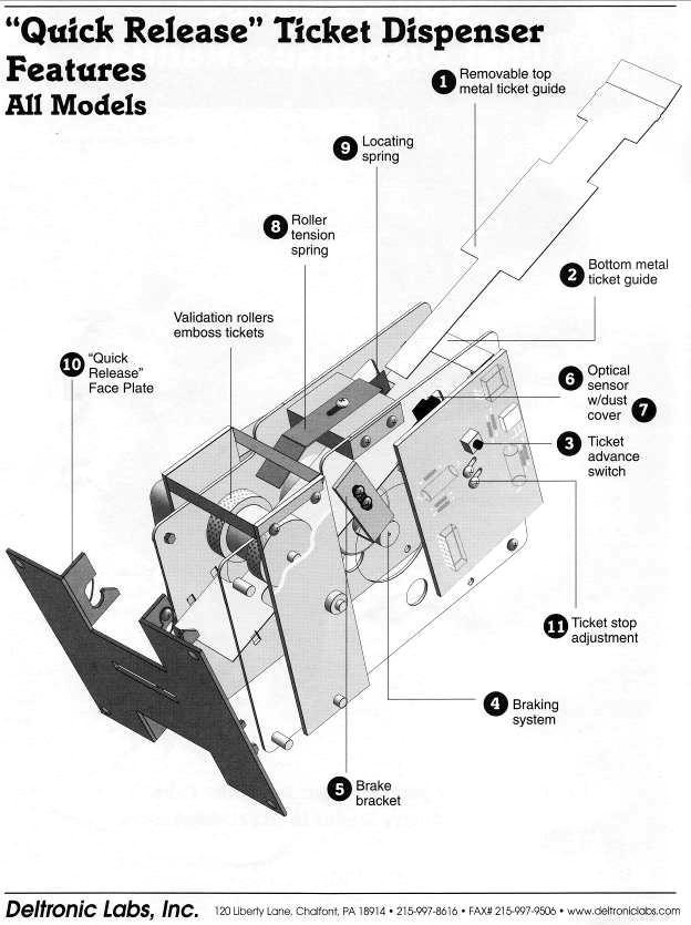
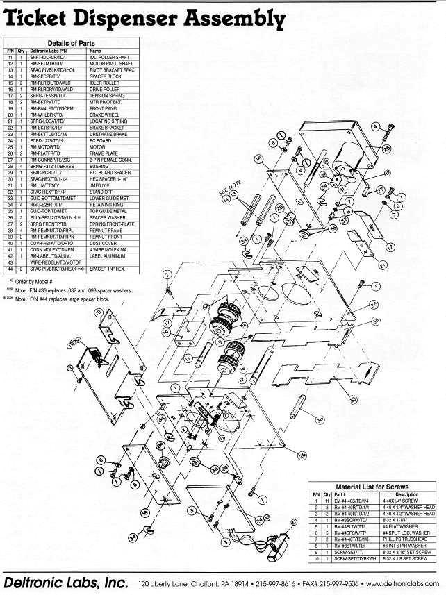
38 TICKET DISPENSER REFERENCE GUIDE Page 35
39 Page 36
40 Page 37
41 Page 38
42 Page 39
43 PRINCESS CASTLE MAIN WIRING Page 40
44 PRINCESS CASTLE MAIN WIRING 1 Page 41
45 PRINCESS CASTLE CONTROL WIRING Page 42
46 PRINCESS CASTLE CONTROL WIRING 1 Page 43
47 PRINCESS CASTLE CONTROL WIRING 2 Page 44
48 PRINCESS CASTLE POWER WIRING Page 45
49 PRINCESS CASTLE OPTIONAL WIRING Page 46

50 DISCLAIMER OPERATOR WILL TAKE NOTE. BY ACCEPTING DELIVERY OF AND PLACING THIS HARDWARE AND LICENSED SOFTWARE INTO OPERATION, OPERATOR REPRESENTS AND WARRANTS THAT IT WILL ONLY OPERATE THE HARDWARE AND LICENSED SOFTWARE PROVIDED BY LAI GAMES IN COMPLIANCE WITH THE REGULATORY REQUIREMENTS OF THE COUNTRY, STATE, AND/OR MUNICIPALITY IN WHICH THE HARDWARE AND LICENSED SOFTWARE ARE USED AND/OR OPERATED. LAI GAMES HAS PROVIDED THIS HARDWARE AND LICENSED THE SOFTWARE ONLY FOR LEGITIMATE AND LEGAL USE, AND ANY USE OF THE HARDWARE AND LICENSED SOFTWARE IN A MANNER THAT VIOLATES ANY LAWS OF THE COUNTRY, STATE, AND/OR MUNICIPALITY IN WHICH THE HARDWARE AND LICENSED SOFTWARE ARE USED AND/OR OPERATED IS WHOLLY UNAUTHORIZED AND SHALL BE AT OPERATOR S SOLE AND COMPLETE RISK. Operator assumes any and all risk and liability for any civil or criminal legal claims or causes of action arising from the unauthorized use and/or operation of the provided hardware and licensed software, such improper and unauthorized use specifically including, but not limited to: (a) Operating or allowing the operation of the hardware and licensed software in a manner that violates the laws and regulations of the country, state, and/or municipality in which the hardware and licensed software are used or operated; (b) Assembling or causing the assembly of the hardware in a manner not authorized by or disclosed in this manual; (c) Any tampering with, changes to, or modifications of the licensed software that occur after the software leaves LAI GAMES factory that is not made by authorized LAI GAMES personnel and that is directly or indirectly caused by Operator; and (d) Any tampering with the computer chip/electronic programmable read only memory (EPROM) by or on behalf of Operator that directly or indirectly causes the tamper-indicating holographic seal on the computer chip/eprom to be broken or damaged in any way. LAI GAMES shall have no liability related to such improper and unauthorized use and/or operation of the hardware and licensed software, and Operator shall indemnify, defend, and hold LAI GAMES harmless for any claim or cause of action brought against LAI GAMES arising from Operator s or Operator s representative s improper and unauthorized use and/or operation of the hardware and licensed software. ANY IMPROPER AND UNAUTHORIZED USE SHALL COMPLETELY AND TOTALLY VOID ANY AND ALL WARRANTIES, BOTH EXPRESS AND IMPLIED, OF THE HARDWARE AND LICENSED SOFTWARE PROVIDED BY LAI GAMES.
51 WARRANTY LAI Games warrants its manufactured products for a period of 3 months inclusive of parts and labor from the date of sale. LAI Games exclusive obligation is to repair any item with any defects as a result of faulty workmanship or materials, providing the defective item or items of equipment are returned to the LAI GAMES distributor from which the machine was purchased. LAI Games shall have no obligation to make repairs necessitated by negligence or interference to any component by any unauthorized personal. This will automatically void any existing warranty. IF MAKING A WARRANTY CLAIM: (a) A Copy of the sales invoice must accompany the claim. (b) To and from Transport and freight costs are not covered by the warranty. (c) Warranty is not transferable with the sale of a machine from one owner to another. LAI Games sales@laigames.com
PLEASE NOTE: LAI Games
 PLEASE NOTE: Read this manual BEFORE operating the machine. Keep this manual for your reference. Go to www.laigames.com click on Operator Access to register your games and receive of future updates. LAI
PLEASE NOTE: LAI Games
 PLEASE NOTE: Read this manual BEFORE operating the machine. Keep this manual for your reference. Go to www.laigames.com click on Operator Access to register your games and receive of future updates. LAI
PLEASE NOTE: LAI GAMES V 1.3
 V 1.3 PLEASE NOTE: Read this manual BEFORE operating the machine. Keep this manual for your reference. Go to www.laigames.com click on Operator Access to register your games and receive of future updates.
LAI GAMES 2004
 www.laigames.com 1st Ed. SKILL July 2004 READ THIS MANUAL BEFORE OPERATING THE MACHINE. KEEP THIS MANUAL FOR YOUR REFERENCE. LAI GAMES Correspondence regarding this machine should be addressed to your
PLEASE NOTE: Version LAI Games
 Version 1.4.2 PLEASE NOTE: Read this manual BEFORE operating the machine. Keep this manual for your reference. Go to www.laigames.com Click on Support to register your Game and receive future updates.
PLEASE NOTE: LAI GAMES V 3.1
 V 3.1 PLEASE NOTE: Read this manual BEFORE operating the machine. Keep this manual for your reference. Go to www.laigames.com click on Operator Access to register your games and receive of future updates.
LAI GAMES
 www.laigames.com READ THIS MANUAL BEFORE OPERATING THE MACHINE. KEEP THIS MANUAL FOR YOUR REFERENCE. LAI GAMES Correspondence regarding this machine should be addressed to your closest LAI GAMES office,
PLEASE NOTE: LAI GAMES V 3.0
 V 3.0 PLEASE NOTE: Read this manual BEFORE operating the machine. Keep this manual for your reference. Go to www.laigames.com click on Operator Access to register your games and receive of future updates.
LAI GAMES READ THIS MANUAL BEFORE OPERATING THE MACHINE. KEEP THIS MANUAL FOR YOUR REFERENCE.
 www.laigames.com READ THIS MANUAL BEFORE OPERATING THE MACHINE. KEEP THIS MANUAL FOR YOUR REFERENCE. LAI GAMES Correspondence regarding this machine should be addressed to your closest LAI GAMES office,
COASTAL AMUSEMENTS, INC, 1950 SWARTHMORE AVE LAKEWOOD, NJ (732)
") OPERATOR S MANUAL COASTAL AMUSEMENTS, INC, 1950 SWARTHMORE AVE LAKEWOOD, NJ 08701 (732) 905-6662 http://www.coastalamusements.com INTRODUCTION Subway Surfers is an amusement redemption game in which the
OPERATOR S MANUAL COASTAL AMUSEMENTS, INC, 1950 SWARTHMORE AVE LAKEWOOD, NJ 08701 (732) 905-6662 http://www.coastalamusements.com INTRODUCTION Subway Surfers is an amusement redemption game in which the
To Purchase This Game, Visit BMI Gaming Or Contact International Sales at (USA) The Simpsons Soccer
 The Simpsons Soccer") The Simpsons Soccer STANDARD OPERATING MANUAL Rev. 9-4-12 (Software Version: 07-30-12) Coastal Amusements, Inc. 1950 Swarthmore Ave. Lakewood, NJ 08701 +1 (732) 905-6662 sales@coastalamusements.com http://www.coastalamusements.com
The Simpsons Soccer STANDARD OPERATING MANUAL Rev. 9-4-12 (Software Version: 07-30-12) Coastal Amusements, Inc. 1950 Swarthmore Ave. Lakewood, NJ 08701 +1 (732) 905-6662 sales@coastalamusements.com http://www.coastalamusements.com
ABOUT SMOKIN' TOKEN EXTREME
 ABOUT SMOKIN' TOKEN EXTREME Operators distinguish Smokin Token as one of the great redemption success stories, and are now able to share in that unprecedented success for yet another generation. Smokin
OPERATION & SERVICE MANUAL FOR FC 110 AC POWER SOURCE
 OPERATION & SERVICE MANUAL FOR FC 100 SERIES AC POWER SOURCE FC 110 AC POWER SOURCE VERSION 1.3, April 2001. copyright reserved. DWG No. FC00001 TABLE OF CONTENTS CHAPTER 1 INTRODUCTION... 1 1.1 GENERAL...
COASTAL AMUSEMENTS, INC, 1950 SWARTHMORE AVE LAKEWOOD, NJ (732)
") OPERATOR S MANUAL Version 1.1 COASTAL AMUSEMENTS, INC, 1950 SWARTHMORE AVE LAKEWOOD, NJ 08701 (732) 905-6662 http://www.coastalamusements.com INTRODUCTION Temple Run 2 is an amusement redemption game in
OPERATOR S MANUAL Version 1.1 COASTAL AMUSEMENTS, INC, 1950 SWARTHMORE AVE LAKEWOOD, NJ 08701 (732) 905-6662 http://www.coastalamusements.com INTRODUCTION Temple Run 2 is an amusement redemption game in
Standard PS-P61 Punch Stapler
 Standard PS-P61 Punch Stapler Instruction Manual Provided By http://www.mybinding.com http://www.mybindingblog.com PUNCH STAPLE PS-P61 Important Information - This manual is designed to help you to install,
TABLE OF CONTENTS. PDF 文件使用 "pdffactory Pro" 试用版本创建
 TABLE OF CTENTS Version: 4.3-003 Time: 2008-3-5 SAFTTY INSTRUCTIS...1 INTRODUCTI...2 PACKAGING...2 ACCERSSORIES...2 TECHNICAL PARAMETERS...2 LOCATI REQUIREMENTS...2 PLAYING INSTRUCTIS...3 ADJUSTING THE
С 800 CASSIDA C 800 HIGH SPEED COIN COUNTER
 С 800 CASSIDA C 800 HIGH SPEED COIN COUNTER This manual contains important information on safety measures and operational features. Please read it carefully before operating your coin counter, and keep
Operator Menus Guide Incredible Technologies, Inc. All Rights Reserved
 Operator Menus Guide 2014 Incredible Technologies, Inc. All Rights Reserved Operator Menus Guide OPERATOR MENUS NAVIGATING THE MENU SYSTEM The Operator Menus allow you to adjust the machine for your specific
BO-01 Blackout. Operation & Service Manual. Version 1.1. * Read this manual before use
 BO-01 Blackout Operation & Service Manual Version 1.1 * Read this manual before use General Remark If you encounter any difficulties or if you need support on how to update and/ or install your Blackout
CANARY AUDIO. Power Amplifier CA-309 OWNER S MANUAL. Handcrafted in California MADE IN USA
 CANARY AUDIO 300B Push-Pull Parallel Power Amplifier Mono Block Handcrafted in California CA-309 OWNER S MANUAL MADE IN USA Dear Customer: Please allow us to take this opportunity to thank you for purchasing
impact VC-500LR Monolight INSTRUCTIONS
 impact lighting equipment and accessories VC-500LR Monolight INSTRUCTIONS Congratulations on your purchase of the Impact VC-500LR Monolight. We feel that it will contribute much to your photographic skill
ApexDesk Assembly Guide
 ELECTRIC HEIGHT-ADJUSTED SIT TO STAND DESK ApexDesk Assembly Guide REV-1507C Table of Contents CAUTION, USE & LIABILITY... 3 PARTS & HARDWARE LIST... 4 PARTS / COMPONENT DIAGRAMS... 5 ASSEMBLY INSTRUCTIONS...
Puppy Jump Operations Manual
 Puppy Jump Operations Manual WARNING Be sure to read this Operation Manual before using your machine to ensure safe operation. 2013 Bob s Space Racers Incorporated 427 15 th Street, Daytona Beach, Florida
PLEASE READ ALL INSTRUCTIONS BEFORE OPERATING THIS MACHINE
 PLEASE READ ALL INSTRUCTIONS BEFORE OPERATING THIS MACHINE TRIGGER HAPPY IS AN EXCITING NEW SHOOTING GALLERY GUN GAME FROM FUN INDUSTRIES. THIS MACHINE IS DESIGNED TO DISPENSE 2 PRIZES AS WELL AS TICKET
INSTALLATION INSTRUCTIONS
 INSTALLATION INSTRUCTIONS FLIP Flip-Down LCD Mount NORTH AMERICA 3130 East Miraloma Avenue Anaheim, CA 92806 USA USA and Canada Phone: 800-368-9700 Fax: 800-832-4888 EUROPE Swallow House, Shilton Industrial
R-Series R235LS 2-Channel Power Amplifier with Local Source Switching
 R-Series R235LS 2-Channel Power Amplifier with Local Source Switching User s Manual On Off R235LS POWER A MPLIFIER IMPORTANT SAFEGUARDS WARNING TO REDUCE THE RISK OF FIRE OR ELECTRIC SHOCK, DO NOT EXPOSE
INSTALLATION INSTRUCTIONS
 INSTALLATION INSTRUCTIONS CTM-MS1 Flat Panel Display Mount (26 to 37 ) NORTH AMERICA 3130 East Miraloma Avenue Anaheim, CA 92806 USA USA and Canada Phone: 800-368-9700 Fax: 800-832-4888 Other Locations
PRC-LA Installation Guide
 1321 S. State College Blvd., Fullerton, CA 92831 USA Weight Limit Maximum Flat Panel Weight: Warning Statements 50 lbs. THE WALL STRUCTURE MUST BE CAPABLE OF SUPPORTING AT LEAST FOUR TIMES THE WEIGHT OF
UPLIFT 2-Leg Height Adjustable Standing Desk
 UPLIFT -Leg Height Adjustable Standing Desk Also watch our assembly video http://bit.ly/9ywwh DIRECTIONS FOR ASSEMBLY AND USE TABLE OF CONTENTS PAGE Safety and Warnings Usage Parts List Assembly Instructions
SOCCERMANIA User manual
 User manual Contents General information - Introduction Page 3 General information - Safety Page 3 Waranty terms Page 4 Machine description Pages 5-6 Main Board description Pages 7-9 MP3 instalation Page
OWNERS AND SERVICE MANUAL 2001 INNOVATIVE CONCEPTS IN ENTERTAINMENT INC.
 OWNERS AND SERVICE MANUAL 2001 INNOVATIVE CONCEPTS IN ENTERTAINMENT INC. 10123 MAIN STREET, CLARENCE, NEW YORK 14031 SERVICE 716-759-0360 SALES 716-759-0370 FAX 716-759-0390 E MAIL play@icegame.com TABLE
Opus 21 s80 Integrated Amplifier Owner's Manual
 Opus 21 s80 Integrated Amplifier Owner's Manual r e s o l u t i o n From all of us at Resolution Audio, thank you for choosing the Opus 21 s80 amplifier. We went to great lengths to design and produce
UPLIFT 2-Leg Height Adjustable Standing Desk - For use with UPLIFT Eco and Eco Curve desktops -
 UPLIFT -Leg Height Adjustable Standing Desk - For use with UPLIFT Eco and Eco Curve desktops - DIRECTIONS FOR ASSEMBLY AND USE TABLE OF CONTENTS Please Note PAGE Safety and Warnings Usage Parts List Assembly
OPERATOR S MANUAL COASTAL AMUSEMENTS, INC, 1950 SWARTHMORE AVE LAKEWOOD, NJ (732)
") a mobile app to coin-op game OPERATOR S MANUAL COASTAL AMUSEMENTS, INC, 1950 SWARTHMORE AVE LAKEWOOD, NJ 08701 (732) 905-6662 http://www.coastalamusements.com INTRODUCTION Rail Rush is an amusement redemption
a mobile app to coin-op game OPERATOR S MANUAL COASTAL AMUSEMENTS, INC, 1950 SWARTHMORE AVE LAKEWOOD, NJ 08701 (732) 905-6662 http://www.coastalamusements.com INTRODUCTION Rail Rush is an amusement redemption
DL102 Counter Loop Amplifier
 DL102 Counter Loop Amplifier USER MANUAL MAN 234A Contents Overview...3 System Includes...3 Maintenance and Recycling Instructions...3 Safety Information...4 Quick Setup...5 Setup...6 Loop Amplifier...6
Wireless Z-Wave Control ZRP-100US Z-Wave Repeater USER MANUAL. Introduction
 Wireless Z-Wave Control ZRP-100US Z-Wave Repeater USER MANUAL Introduction Thank you for choosing ZRP-100 Z-Wave Repeater product! ZRP-100 is a Z-Wave repeater with best RF performance to repeat Z-Wave
CONNECTOR (10PIN) BLACK BEARD PARTS SIDE
 BLACK BEARD PARTS SIDE") CONNECTOR (10PIN) PARTS SIDE SOLDER SIDE GND 1 GND GND 2 GND (*1) +5V 3 +5V +5V 4 +5V (*1) +12V 5 +12V +12V 6 +12V Ticket Dispenser Enable 7 (*2) Hopper SSR 8 GND 9 GND GND 10 GND (1) DC +5V 2A and DC
CONNECTOR (10PIN) PARTS SIDE SOLDER SIDE GND 1 GND GND 2 GND (*1) +5V 3 +5V +5V 4 +5V (*1) +12V 5 +12V +12V 6 +12V Ticket Dispenser Enable 7 (*2) Hopper SSR 8 GND 9 GND GND 10 GND (1) DC +5V 2A and DC
ATTENTION! There is only ONE set of keys per machine. Locks and keys CANNOT be replaced. PLEASE keep your keys in a safe place.
 Instruction Manual ATTENTION! This manual is for reference only. Each machine will be a little different depending upon model and manufacturer. All slot machines essentially program and play the same.
INSTRUCTION MANUAL INF Fax: (503)
") INSTRUCTION MANUAL INF151 1-800-547-5740 Fax: (503) 643-6322 www.ueiautomotive.com email: info@ueitest.com Introduction Congratulations on your purchase of the INF151 infrared thermometer. Like all UEi
INSTRUCTION MANUAL INF151 1-800-547-5740 Fax: (503) 643-6322 www.ueiautomotive.com email: info@ueitest.com Introduction Congratulations on your purchase of the INF151 infrared thermometer. Like all UEi
Keychain Radio Remote Control System
 Innovation in Mobility Keychain Radio Remote Control System Operator Manual 04/23/02 95-2002 RICON CORPORATION All Rights Reserved U.S. and foreign patents pending Printed in the United States of America
Service Manual Innovative Concepts in Entertainment
 Service Manual Innovative Concepts in Entertainment 10123 Main Street Clarence, New York 14031 (716) 759-0360 www.icegame.com Table of Contents What s included 3 Safety and Warnings 4 Game Assembly 5-9
UPLIFT 3-Leg Desk Instructions for. Solid Wood Desktops. pictured: 3-leg desk; solid-wood top, with right hand return TABLE OF CONTENTS
 UPLIFT 3-Leg Desk Instructions for Solid Wood Desktops pictured: 3-leg desk; solid-wood top, with right hand return TABLE OF CONTENTS PAGE 1 Safety and Warnings 2 2 Usage 2 3 Parts List 3 4 Assembly Instructions
OWNER S MANUAL DANGER
 OWNER S MANUAL The actual product you have received may differ slightly from the illustration. DANGER To ensure safe operation of the product, be sure to read this Operation Manual before use. Keep this
FD 1202 AutoSeal Tabletop Pressure Sealer
 FD 1202 AutoSeal Tabletop Pressure Sealer 4/2015 OPERATOR MANUAL FIRST EDITION TABLE OF CONTENTS TOPIC PAGE SPECIFICATIONS 1 UNPACKING, COMPONENTS 2 SET-UP 3 OPERATION 5 DETERMINING FOLD TYPE 6 ADJUSTING
OWNER S MANUAL DANGER
 OWNER S MANUAL The actual product you have received may differ slightly from the illustration. DANGER To ensure safe operation of the product, be sure to read this Operation Manual before use. Keep this
Rock Sounders. Weatherproof Wireless 900MHz Speaker System. User Guide. Model no.: GDI-AQRCK400 / AQRCK41
 Rock Sounders Weatherproof Wireless 900MHz Speaker System User Guide Model no.: GDI-AQRCK400 / AQRCK41 Please read before using the equipment IMPORTANT: Please read your User s Guide before using your
Installation and Operation Manual MSI. Multi-Sensor Interface Hub. Interface Module for all Sensors Network and Wireless CAUTION
 Installation and Operation Manual MSI Multi-Sensor Interface Hub Interface Module for all Sensors Network and Wireless CAUTION This equipment complies with the limits for a Class B digital device, pursuant
FOLDING MACHINE PF-45A OPERATOR MANUAL 1. FUNCTION
 FOLDING MACHINE OPERATOR MANUAL 1. FUNCTION The folding machine is used to fold documents stand alone or in combination with a system 7. Sheets can be folded in various types. These are: single fold; letter
USER MANUAL ENGLISH 1450 COIN COUNTER & SORTER
 USER MANUAL ENGLISH 1450 COIN COUNTER & SORTER INTRODUCTION ENGLISH Thank you for purchasing the Safescan 1450 coin counter and sorter. For proper use and maintenance, we advise to read this user manual
Schooners II. Weatherproof Wireless 900MHz Speaker System. User Guide. Model no.: GDI-AQSHR200 / AQSHR21
 Schooners II Weatherproof Wireless 900MHz Speaker System User Guide Model no.: GDI-AQSHR200 / AQSHR21 IMPORTANT: Please read your User s Guide before using your system INTRODUCTION Your SCHOONERS II speaker
INTEGRATED HYBRID TUBE AMPLIFIER VT Model HYBRID TUBE AMPLIFIER
 INTEGRATED HYBRID TUBE AMPLIFIER Model VT-40.2 HYBRID TUBE AMPLIFIER OWNER S MANUAL Safety Instructions The lightning flash with the arrowhead symbol within an equilateral triangle is intended to alert
DRO 100 REFERENCE MANUAL
 DRO 100 REFERENCE MANUAL Warranty ACU-RITE Products and accessories are warranted against defects in material and workmanship for a period of three years from the date of purchase. ACU-RITE will, at its
CM3000. Operator s Manual. ChangeMaker. Seaga Manufacturing, Inc. 700 Seaga Drive Freeport, IL USA
 CM3000 ChangeMaker Operator s Manual Seaga Manufacturing, Inc. 700 Seaga Drive Freeport, IL USA 61032 www.seagamfg.com INTRODUCTION Congratulations on the purchase of your new ChangeMaker. This ChangeMaker
Models 2230 and 2240
 Models 2230 and 2240 Overview... 2 Tools Needed... 2 Hardware...3 Assembly... 4-13 Installation... 14 Drawer Removal... 15 Operation... 15 Maintenance... 15 Accessories... 16 Limited Warranty... 16 Perform
2015 RIGOL TECHNOLOGIES, INC.
 Service Guide DG000 Series Dual-channel Function/Arbitrary Waveform Generator Oct. 205 TECHNOLOGIES, INC. Guaranty and Declaration Copyright 203 TECHNOLOGIES, INC. All Rights Reserved. Trademark Information
P4263TP. Installation Guide. Low-Profile Tilting Portrait Mount for Flat-Panels
 Low-Profile Tilting Portrait Mount for Flat-Panels 1321 S. State College Blvd., Fullerton, CA 92831 USA Weight Limit Maximum Flat Panel Weight: 175 lbs. Warning Statements THE WALL STRUCTURE MUST BE CAPABLE
Model S-520 Coin Counter / Sorter Operating Manual
 Model S-520 Coin Counter / Sorter Operating Manual Table of Contents Using the Product Safely... 2 About the Warning Stickers and Points of Warning/... 2 Warning.... 3. 4 Names of the Main Parts......
TABLE OF CONTENTS 1 BRIEF INSTRUCTION NOTICE... 1
 TABLE OF CONTENTS Ver:1.01 Time:2010-12-16 1 BRIEF INSTRUCTION... 1 2 NOTICE... 1 2-1. SAFTTY INSTRUCTIONS...1 2-2. NOTICE FOR OPERATION...1 3 ACCESSORIES... 1 4 HOW TO PLAY... 2 5 TECHNICAL PARAMETERS...
PORTABLE HALOGEN WORK LIGHT OWNER S MANUAL
 PORTABLE HALOGEN WORK LIGHT OWNER S MANUAL L-9001 (29278) L-9002 (29276) WARNING: Read carefully and understand all ASSEMBLY AND OPERATION INSTRUCTIONS before operating. Failure to follow the safety rules
Operators Manual (Manual A)
") CD201 SINGLE COLUMN CARD DISPENSER Operators Manual (Manual A) Contents A1 Scope... 1 A2 Specifications... 1 A3 Installation... 2 3.1 Unpacking and inspection... 2 3.2 Opening and closing the door... 2
CD201 SINGLE COLUMN CARD DISPENSER Operators Manual (Manual A) Contents A1 Scope... 1 A2 Specifications... 1 A3 Installation... 2 3.1 Unpacking and inspection... 2 3.2 Opening and closing the door... 2
léìë=on ëpm=fåíéöê~íéç=^ãéäáñáéê lïåéêdë=j~åì~ä êéëçäìíáçå
 léìë=on ëpm=fåíéöê~íéç=^ãéäáñáéê lïåéêdë=j~åì~ä êéëçäìíáçå From all of us at Resolution AV, thank you for choosing the Opus 21 s30 amplifier. We went to great lengths to design and produce an integrated
INSTALLATION INSTRUCTIONS
 INSTALLATION INSTRUCTIONS Compact Power Amplifier NORTH AMERICA 3130 East Miraloma Avenue Anaheim, CA 92806 USA USA and Canada Phone: 1.800.368.9700 Fax: 1.800.832.4888 Other Locations Phone: (001).714.632.7100
UPLIFT Height Adjustable Standing Desk 3-Leg (T-Frame) DIRECTIONS FOR ASSEMBLY AND USE
 DIRECTIONS FOR ASSEMBLY AND USE") UPLIFT Height Adjustable Standing Desk 3-Leg (T-Frame) DIRECTIONS FOR ASSEMBLY AND USE CAUTION MAKE SURE NO OBSTACLES ARE IN THE DESK S PATH AND ALL CORDS ARE OF APPROPRIATE LENGTH FOR DESK TRAVEL. FAILURE
UPLIFT Height Adjustable Standing Desk 3-Leg (T-Frame) DIRECTIONS FOR ASSEMBLY AND USE CAUTION MAKE SURE NO OBSTACLES ARE IN THE DESK S PATH AND ALL CORDS ARE OF APPROPRIATE LENGTH FOR DESK TRAVEL. FAILURE
INSTALLATION MANUAL PBL-UMP
 INSTALLATION MANUAL PBL-UMP Table of Contents Warning Statements... 4 Parts List... 5 Installation Tools... 5 Features... 7 Projector Preparation... 8 Bracket Installation... 10 Leveling the Mounting Bracket...
INSTALLATION MANUAL PBC-UMS
 INSTALLATION MANUAL. PBC-UMS Premier Mounts 3130 E. Miraloma Avenue Anaheim, CA 92806 Phone: (800) 368-9700 Fax: (800) 832-4888 mounts@mounts.com www.mounts.com Rev. 01 PBL-110 Projector Mount Page 2 Installation
CR31. Companion. Instruction Manual
 CR31 Companion Instruction Manual 910-244700-001 IMPORTANT SAFETY INSTRUCTION PLEASE READ CAREFULLY ALL THE FOLLOWING IMPORTANT SAFEGUARDS THAT ARE APPLICABLE TO YOUR EQUIPMENT 1. Read Instructions - All
Model CC4041. CC Series Amplifier. Installation and Use Manual
 BASS 0 TREBLE 0-12 +12-12 +12 INPUT 1 INPUT 2 INPUT 3 INPUT 4 PEAK SIGNAL POWER POWER CC Series Amplifier Model CC4041 Installation and Use Manual 2012 Bogen Communications, Inc. All rights reserved. Specifications
INSTALLATION INSTRUCTIONS
 CREATING POSITIVE CUSTOMER EXPERIENCES INSTALLATION INSTRUCTIONS Universal Low Profile Tilt Mount for 42 to 63 Flat Panels NORTH AMERICA 3130 East Miraloma Avenue Anaheim, CA 92806 USA USA and Canada Phone:
VAN STORAGE SOLUTIONS FOR THE WAY YOU WORK
 WWW.WEATHERGUARD.COM VAN STORAGE SOLUTIONS FOR THE WAY YOU WORK Weather Guard / KNAACK 420 E. Terra Cotta Ave. Crystal Lake, IL 60014 USA 800-456-7865 (Toll Free) 800-334-2981 (Fax) Knaack.OrderEntry@wernerco,.com
SHIRTS AND SKINS JUNIOR EDITION COASTAL AMUSEMENTS INC SWARTHMORE AVE LAKEWOOD, NJ TEL: FAX:
 SHIRTS AND SKINS JUNIOR EDITION COASTAL AMUSEMENTS INC. 1935 SWARTHMORE AVE LAKEWOOD, NJ 08701 TEL: 732-905-6662 FAX: 732-905-6815 W632 SHIRTS AND SKINS FUSE AT MAIN BOARDS F1, 20 mm 2A GATE MOTOR; F2,
CANARY AUDIO. EL34 Stereo Power Amplifier. Handcrafted in California CA-770 OWNER S MANUAL MADE IN USA
 CANARY AUDIO EL34 Stereo Power Amplifier Handcrafted in California CA-770 OWNER S MANUAL MADE IN USA Dear Customer: Please allow us to take this opportunity to thank you for purchasing this CANARY AUDIO
INTEGRATED VACUUM TUBE AMPLIFIER LM-508IA
 INTEGRATED VACUUM TUBE AMPLIFIER LM-508IA Table of Contents Thanks for choosing our Line Magnetic LM-508IA Integrated Amplifier as an important part of your music system and please read the manual carefully
AutoSeal FD 1506 Plus / FE 1506 Plus
 AutoSeal FD 1506 Plus / FE 1506 Plus FK / FL SERIES 06/2018 OPERATOR MANUAL FIRST EDITION TABLE OF CONTENTS DESCRIPTION 1 UNPACKING AND SET-UP 2 CONTROL PANEL 3 OPERATION 3 FOLD PLATE ADJUSTMENT 4 SETTING
INSTALLATION INSTRUCTIONS
 INSTALLATION INSTRUCTIONS AM2 / AM2-B Articulating Swingout Arm NORTH AMERICA 3130 East Miraloma Avenue Anaheim, CA 92806 USA USA and Canada Phone: 1.800.368.9700 Fax: 1.800.832.4888 Other Locations Phone:
KRAMER ELECTRONICS LTD. USER MANUAL MODEL: 912 Power Amplifier. P/N: Rev 2
 KRAMER ELECTRONICS LTD. USER MANUAL MODEL: 912 Power Amplifier P/N: 2900-000684 Rev 2 Contents 1 Introduction 1 2 Getting Started 2 2.1 Achieving the Best Performance 2 3 Overview 3 3.1 Defining the 912
the slim retracting clothesline product manual
 &6 the slim retracting clothesline product manual for 4 and 6-line models HLS0046_4-6 line_owners Manual_v6.indd 1 2 Introduction Congratulations Congratulations on the purchase of your new Hills slim
.VEGAS NIGHT. The following developer is responsible for the declaration: (Manual Version: VEG_INT _7B) VEG_INT _7B 1
 VEG_INT _7B 1") .VEGAS NIGHT. The following developer is responsible for the declaration: Astro Corp. 10F, No.111-1, HSING DE RD, SANCHUNG CITY, TAIPEI COUNTY, TAIWAN Telephone:+886-2-8511-0555 Facsimile:+886-2-8511-0556
.VEGAS NIGHT. The following developer is responsible for the declaration: Astro Corp. 10F, No.111-1, HSING DE RD, SANCHUNG CITY, TAIPEI COUNTY, TAIWAN Telephone:+886-2-8511-0555 Facsimile:+886-2-8511-0556
ATD AMP Variable Speed Reciprocating Saw Owner s Manual
 ATD-10535 7 AMP Variable Speed Reciprocating Saw Owner s Manual Manufactured in China To ATD Tools, Inc. Specifications TECHNICAL SPECIFICATIONS Voltage: 120V Frequency: 60Hz Power input: 7 Amps No load
INSTALLATION INSTRUCTIONS
 CREATING POSITIVE CUSTOMER EXPERIENCES INSTALLATION INSTRUCTIONS PDS-PLUS Universal Projector Mount Model: NORTH AMERICA 3130 East Miraloma Avenue Anaheim, CA 92806 USA USA and Canada Phone: 1.800.368.9700
AV30MX-2 Operation Manual
 AV30MX-2 Operation Manual 1 Important safety instructions 1. Please read carefully prior to product installation or operation. 2. Read these instructions. 3. Keep these instructions. 4. Heed all warnings.
plifier D-501 otion Am Tactile M
 Tactile Motion Amplifier D-501 IMPORTANT SAFETY INSTRUCTIONS WARNING: 1. Read and keep these instructions for future reference. 2. Do not use this apparatus near water. 3. Clean only with a dry cloth.
OPERATION AND SERVICE MANUAL
 KCM-D Coin Changer (Version of EURO coins) OPERATION AND SERVICE MANUAL 1 TABLE OF CONTENTS Chapter 1: General Information Introduction ----------------------------------------------------------------------------------------------------2
SI-125 Power Amplifier Manual 6205 Kestrel Road; Mississauga, Ontario; Canada; L5T 2A1 November 2016, Rev 0.5
 SI-125 Power Amplifier Manual 6205 Kestrel Road; Mississauga, Ontario; Canada; L5T 2A1 November 2016, Rev 0.5 Phone: (905) 564-0801 Fax: (905) 564-0806 www.telecor.com E:\T2-108\T2-M108-ABC\T2-M108-B.doc/AD
Multi Drop Bus 5-Tube Coin Changer. Series. Service Manual B D A C E SAT
 Multi Drop Bus 5-Tube Coin Changer Series Service Manual DIS C/C A C E MOD B D SAT AUT 2 TABLE OF CONTENTS Page 1 Outline... 3 2 Product Model Names... 4 3 General Specifications... 5 4 Detailed Specifications...
AMP SELECTOR Owner s Manual
 AMP SELECTOR Owner s Manual Version 1.0 VOODOO LAB AMP SELECTOR User s Manual Introduction The Voodoo Lab Amp Selector is the ultimate stand-alone tool for switching your guitar into multiple amplifiers.
Installation & Operation Manual SAGA1-K Series Industrial Radio Remote Control
 Installation & Operation Manual SAGA1-K Series Industrial Radio Remote Control Gain Electronic Co. Ltd. Table Of Contents Safety Considerations ------------------------------------------------------------2
Broadband Step-Up Transformer. User Manual
 Broadband Step-Up Transformer User Manual 990-1930 09/2004 Introduction Introduction About this unit The APC Step-Up Transformer provides 220 V power from 60 VAC Broadband cable systems. Safety Electrical
Models 2030 and 2040
 Models 2030 and 2040 Overview... 2 Tools Needed... 2 Hardware... 2 Assembly... 3-8 Installation... 9 Operation... 9 Maintenance... 10 Accessories... 10 Limited Warranty... 10 Document # 101290 0607 Printed
Model CC4052. CC Series Amplifier. Installation and Use Manual
 CC Series Amplifier Model CC4052 Installation and Use Manual 2012 Bogen Communications, Inc. All rights reserved. Specifications subject to change without notice. 54-2216-01A 1303 NOTICE: Every effort
NOVA-EXT Versatile Projector Mount Model: NOVA-EXT
 INSTALLATION MANUAL NOVA-EXT Versatile Projector Mount Model: NOVA-EXT NORTH AMERICA 3130 East Miraloma Avenue Anaheim, CA 92806 USA USA and Canada Phone: 800-368-9700 Fax: 800-832-4888 Other Locations
Classic Series Public Address Amplifiers C10 & C20 Models
 Classic Series Public Address Amplifiers C10 & C20 Models Installation and Use Manual 2009 Bogen Communications, Inc. All rights reserved. Specifications subject to change without notice. 54-5978-01B 0901
HTA125A/250A. Power Amplifiers. Installation & Use Manual
 HTA125A/250A Power Amplifiers Installation & Use Manual Specifications subject to change without notice. 2010 Bogen Communications, Inc. All rights reserved. 54-5832-04B 1011 NOTICE: Every effort was made
INSTRUCTION MANUAL. MODEL: Vintage 60R. Vintage Series Guitar Amplifi er
 INSTRUCTION MANUAL MODEL: Vintage 60R Vintage Series Guitar Amplifi er 2 INTRODUCTION Thank you for choosing this Johnson amplifier. Please read this manual carefully and completely before operating your
OPERATING INSTRUCTIONS
 OPERATING INSTRUCTIONS FOR ASSISTANCE: Voice: (888) 595-9759 E-Mail: info@shuffletech.com Address: 1440 N. Kingsbury Suite 218 Chicago, IL 60642 Website: www.shuffletech.com PLEASE READ THESE OPERATING
AQ-SWA8-1BT - ACTIVE SUBWOOFER USER / INSTALLATION MANUAL. with Bluetooth & Full Range Speaker Outputs
 AQ-SWA8-1BT - ACTIVE SUBWOOFER with Bluetooth & Full Range Speaker Outputs USER / INSTALLATION MANUAL PLEASE READ THIS INSTRUCTION MANUAL BEFORE INSTALLATION AND OPERATION Table of Contents 1 Introduction...
MBM 307A / 407A PF Automatic Folders
 MBM 307A / 407A PF Automatic Folders Instruction Manual Provided By http://www.mybinding.com http://www.mybindingblog.com OPERATION MANUAL MBM 307A / 407A AUTOMATIC FOLDERS 1-800-223-2508 www.mbmcorp.com
USER'S GUIDE. EcoQuest International 310 T. Elmer Cox Drive Greeneville, TN (423) Setup. Operation. Specifications.
 Setup. Operation. Specifications.") USER'S GUIDE Setup Operation Specifications Warranty (43) 638-746 CAUTION: Read manual carefully for proper procedures and operation. CONTENTS SPECIFICATIONS Specifications...............................................................3
USER'S GUIDE Setup Operation Specifications Warranty (43) 638-746 CAUTION: Read manual carefully for proper procedures and operation. CONTENTS SPECIFICATIONS Specifications...............................................................3
Operator Manual. Booklet Maker BM 60. Doc No. T10171
 Booklet Maker BM 60 Operator Manual Doc No. T10171 Morgana Systems Limited United Kingdom www.morgana.co.uk Telephone: ( 01908 ) 608888 Facsimile: ( 01908 ) 692399 Part no: 60249 Doc no: T10171 Rev. date:
MZ2 HEADPHONE AMPLIFIER, PREAMP, & STEREO AMPLIFIER USER GUIDE
 MZ2 HEADPHONE AMPLIFIER, PREAMP, & STEREO AMPLIFIER USER GUIDE Linear Tube Audio Takoma Park, MD, USA WARNING: For safety, the cover of this amplifier should be secured at all times. DC voltages as high
OPERATION MANUAL MBM 207M MANUAL FOLDER
 OPERATION MANUAL MBM 207M MANUAL FOLDER 1-800-223-2508 www.mbmcorp.com 1 Safety Instructions Definition of Symbols and Notes The following names and signs stand for possible dangers: Danger This symbol