To Purchase This Item, Visit BMI Gaming (800)
|
|
|
- Margaret Washington
- 5 years ago
- Views:
Transcription


1 OWNERS AND SERVICE MANUAL INNOVATIVE CONCEPTS IN ENTERTAINMENT INC MAIN STREET, CLARENCE, NY SERVICE: FAX: WEBSITE: 1
2 INTRODUCTION GAME FEATURES GAME PLAY ASSEMBLY BEFORE YOU BEGIN TOOLS NEEDED INSTALLATION SETTING A.C. LINE VOLTAGES A.C. LINE VOLTAGE ADJUSTMENTS SET-UP / TESTING SAFETY PRECAUTIONS PROGRAMMING YOUR GAME OPTION MODES TESTING QUICK TROUBLESHOOTING PROBLEMS AND SOLUTIONS REPAIR OPERATIONAL BACKGROUND MECHANICAL REPAIR ELECTRICAL / ELECTRONIC REPAIR MAINTENANCE PARTS LISTINGS SCHEMATICS WARRANTY INFORMATION TABLE OF CONTENTS 2
3 GAME FEATURES Thank you for your purchase of the new ICE BALL Alley Roller game from I.C.E. Through extensive testing and consultation with game operators, we have developed a game with all of the features and serviceability you ve been asking for. We have gone to great lengths to manufacture an Alley Roller game that is far easier to service and operate than anything before it. The features we have added, truly bring this game up to date. The game starts off with unparalleled ease of assembly. The game goes together in just a few minutes. INTRODUCTION Another important feature of our game is the operator selectable Balls per game. This feature allows the operator to control how many balls the game will normally deliver. This amount is adjustable from 1 to 20 balls per game. It is however important to note that THE BALLS PER GAME IS NOT RELATED TO HOW MANY BALLS ARE IN THE GAME. The quantity of balls in the game is only for reference based on the normal 9 balls given in the traditional game. The game will work with 1 to 15 balls in the game, yet deliver the proper amount programmed into the game every time. (It is a good idea however to have at least 3 balls in the game to avoid slow play) The game cabinetry is a unique plywood construction with a special overlay for a superior finish. A special lacquer finish is applied over the wood for a beautiful rich, deep look. All of the cabinet panels interlock together, are reinforced with cleats and are glued together to produce a cabinet that can handle all of the abuse you can give it. Loading tickets is a snap, with our easy pull out drawer. This new feature drastically reduces the time needed to load tickets, as well as making it much to service ticket jams or the dispenser. Long life fluorescent lighting is used throughout the game to lower maintenance and create a bright playfield area. Even the ball return area is back lit to add to the appearance and serviceability of the game. Reliability is the name of the game with our new ball release assembly. With a specially engineered solenoid and double linkages, this mechanism has been tested to last for years. Best of all, the entire assembly simply lifts out of the cabinet with no tools needed! The best state of the art sound on sound audio is used to create an exciting atmosphere for the game player. Even our background theme is synchronized so all games play the theme at the same time, even when only one game is being played. ICE BALL allows the operator to give the players extra balls when a certain point threshold is reached. In addition, double scores can be awarded if desired. This extends the total points possible and adds a great deal to player appeal. These features also add excitement when used in conjunction with the optional Jackpot Marquee. All programming is accomplished from the Main P.C. Board which is conveniently located at the front end of the cabinet. This make servicing and adjusting as easy as turning a key. GAME PLAY Game play begins when a player has inserted enough money into the game to create 1 Credit. At this point, the Start button begins to flash. When the start button is pressed, the balls release from the game and the game begins. The player throws balls at the target pockets and is awarded the points indicated on those pockets. The player continues to throw balls until they are all used up. If the player breaks a predetermined score during game play, he may be entitled to get Free Balls. At the end of the game, the game will dispense tickets based on score. (If the game is so equipped) If the player gets a New High Score or Extended Play the rotating Beacon light will turn on. The Beacon light will also turn on if the player has won the ticket jackpot from the Optional Jackpot Marquee. 3
4 BEFORE YOU BEGIN WARNING: WHEN INSTALLING THIS GAME, A 3 PRONG GROUNDED A.C. RECEPTACLE MUST BE USED. FAILURE TO DO SO COULD RESULT IN SERIOUS INJURY TO YOURSELF OR OTHERS. FAILURE TO USE A GROUNDED RECEPTACLE COULD ALSO CAUSE IMPROPER GAME OPERATION, OR DAMAGE TO THE ELECTRONICS DO NOT DEFEAT OR REMOVE THE GROUNDING PRONG ON THE POWER CORD FOR THE SAME REASONS AS GIVEN ABOVE. USING AN IMPROP- ERLY GROUNDED GAME COULD VOID YOUR WAR- RANTY. HAVE A QUALIFIED ELECTRICIAN CHECK YOUR A.C. RECEPTACLE TO BE SURE THE GROUND IS FUNCTIONING PROPERLY. TOOLS NEEDED Large Allen Key (Supplied) Phillips head screwdriver INSTALLATION 1. Remove the banding from the pallet. NOTE: BE SURE TO STAND TO THE SIDE WHEN CUTTING THE BANDS, AS THEY ARE UNDER PRESSURE, AND COULD SPRING OUT CAUSING INJURY. 2. Lift out all cage parts as well as any other parts shipped along with the game. 3. Remove the 2 game halves from the pallet. 4. Set the rear of the game into the approximate location of where it will be located. If assembling more than 1 game, you must leave space to run the power cords and linking phone cord. 5. Set the front cabinet into position in front of the rear cabinet. 6. Open the coin and ticket doors and slide the left side cover forward enough to connect the harnessing from the rear cabinet to the front cabinet. 7. Slide the left hand cover back on. ASSEMBLY 8. Slide the front cabinet into position. Insert the large Allen key into the holes on the sides of the front cabinet and rotate the Allen key 180 to lock the cabinet halves together. 9. Slide the right hand cover from the game. 10. Remove the packing material from around the ball release assembly. NOTE: KEEP THE PACKING MATERIAL FOR THE BALL RELEASE ASSEMBLY BEHIND THE GAME IN CASE YOU DECIDE TO MOVE YOUR GAME LATER. 11. Open the parts box containing the balls and install them into the ball return release. (There should be 9 balls supplied with the game) 12. Slide the right hand cover back onto the game. 13. Open the electronics access door. (Door in between the ticket and coin drawers) 14. On each Main P.C. Board are 2 modular phone jacks. Connect a phone line from game to game, plugging 1 end into each game. Feed the phone lines through a wiring hole located in the rear of the electronic enclosure. It does not matter which jack you plug the phone line into on the board as long as the phone lines are connected from game to game. If you are installing a Jackpot Marquee, it can be connected to any open phone jack on any game. 15. Connect the long Computer style power cord to the Power Module. The power module is located inside the Electronics access door, to the lower right. Connect the other end to a grounded A.C. outlet.* * Be sure before plugging the game in that it is wired for the proper A.C. voltage. One way to check is by looking at the game s serial number tag. It will indicate the rated voltage on it. If you are still unsure about what the game s voltage is set for, please refer to the Setting A.C. line voltages section in this manual. 4
5 SETTING A.C. LINE VOLTAGES The game comes with 4 available line voltage settings as described below. These settings should be used to provide A.C. power in the correct range to the game without over or under powering it. POWER RANGE VOLTAGE SETTING ASSEMBLY Snap the fuse holder assembly back into the power module. Plug the power cord back into the receptacle in the power module, and into the wall outlet. NOTE: WHEN CHANGING VOLTAGES FROM THE TO RANGE, LOWER THE MAIN FUSE AMERAGE VALUE BY ½ V.A.C V.A.C V.A.C V.A.C. 240 WHEN CHANGING FROM THE TO VOLT RANGE, DOUBLE THE MAIN FUSE AMPERAGE VALUE. The game uses a POWER MODULE to handle all of the A.C. power distribution chores of the game. It incorporates an On-Off switch, primary A.C. game fusing, and power switching capabilities. This allows the game to be used with a wide variety of A.C. voltages by re-strapping the main transformer. A.C. LINE VOLTAGE ADJUSTMENT To adjust the game for a different A.C. voltage: Unplug the game from the outlet. Disconnect the power cord from the power module. Using a small flat blade screwdriver, pry the fuse holder from the power module. Notice a small window on the fuse holder with an arrow that points to the voltage the game is presently set at. Using a small flat blade screwdriver, lift the retaining tab that holds the voltage selector in the fuse holder. Rotate the voltage selector until the voltage you want is displayed in the voltage select window. Push the voltage selector back into the fuse holder until it snaps into place. NOTE: Do not force the selector into the fuse holder. If it does not go in easily, it is not being installed correctly. 5
6 SET-UP / GAME TESTING SAFETY PRECAUTIONS IMPORTANT: FAILURE TO FOLLOW THESE DIRECTIONS COULD CAUSE SERIOUS DAMAGE TO YOU OR YOUR GAME. WARNING: WHEN INSTALLING THIS GAME, A 3 PRONG GROUNDED A.C. RECEPTICLE MUST BE USED. FAILURE TO DO SO COULD RESULT IN SERI- OUS INJURY TO YOURSELF OR OTHERS. FAILURE TO USE A GROUNDED RECEPTICLE COULD ALSO CAUSE IMPROPER GAME OPERATION, OR DAMAGE TO THE ELECTRONICS DO NOT DEFEAT OR REMOVE THE GROUNDING PRONG ON THE POWER CORD FOR THE SAME REASONS AS GIVEN ABOVE. USING AN IMPROP- ERLY GROUNDED GAME COULD VOID YOUR WAR- RANTY. HAVE A QUALIFIED ELECTRICIAN CHECK YOU RE A.C. RECEPTICLE TO BE SURE THE GROUND IS FUNCTIONING PROPERLY. REPLACE ALL INCANDESCENT BULBS WITH PROPER ICE SUPPLIED BULBS ONLY PROGRAMMING BUTTON (PGM / SW1) This button is used to enter and exit the programming mode. Use this button to change game settings or to remotely change settings on the optional Jackpot Marquee. Press this button once to enter programming mode. When in this mode, the game displays will display information pertinent to game programming. Press this button once again to exit programming mode. Once in this mode, you can push SW2, SW3 or SW4 to make adjustments to the game. SELECT BUTTON (SEL / SW2) This button is used to advance through all of the various programming option modes. Each push of this button will move you to the next programmable option. The option number is displayed in the Balls Left display. PROGRAMMING YOUR GAME This section will give you a detailed explanation of the functions and operating characteristics of each of the programming buttons. PLEASE READ THIS SECTION CAREFULLY TO AVOID PROBLEMS WITH YOUR GAME. NOTE: THE PROGRAMMING AND TEST BUT- TONS ARE LOCATED ALONG THE FRONT EDGE OF THE MAIN P.C. BOARD WHICH IS LOCATED BEHIND THE ELECTRONICS ACCESS DOOR. THIS DOOR IS BETWEEN THE TICKET AND COIN DRAWERS AT THE FRONT OF THE GAME. STEP UP BUTTON (UP / SW3) This button is used to change the VALUE of a particular option mode. The operation mode values are displayed on the Score display. Each push of this button changes to the next HIGHER available value for that mode. STEP DOWN BUTTON (DOWN / SW4) This button is used to change the VALUE of a particular option mode. Each push of this button changes to the next LOWER available value for that mode. 6
7 SET-UP / GAME TESTING TEST BUTTON (TEST / SW5) MODE 00 (VOLUME) This button is used for factory burn-in of the game electronics. It is also very helpful to be sure all game functions work correctly. When in this mode, the following things will happen: Game release solenoid will cycle on and off Displays will count down displaying similar numbers. (Ex.: all 9 s or 8 s) Beacon light will cycle on and off. Closing any score (playfield) switch by throwing a ball will create an audible sound. Pushing the start button, coin switch or low ticket micro switch will create an audible sound. Game theme song will constantly play. To exit the test mode, press the programming button. AUDIO TEST BUTTON (AUDIO TEST / SW6) Pressing this button will cause the game s theme song to play. This is used to prove that the audio microprocessor is talking to the logic microprocessor properly. This is a useful Main P.C. Board troubleshooting procedure. OPTIONS MODES Please the setting information carefully BEFORE making any adjustments. Failure to set options properly can yield unexpected results. PLEASE NOTE: THE VALUES PRE-SET AT THE FACTORY HAVE BEEN FOUND TO WORK BEST FOR MOST LOCATIONS. This option is used to change the relative sound volume of the game. 1 is the lowest the game can be set to play at while 4 is the loudest. Each time the button is pushed, a sound is played to make it easier to determine where the volume level should be set. The factory default for this option mode is 3. MODE 01 (COINS PER CREDIT) COIN INPUT #1 This mode determines how many coins are needed to create 1 credit for coin input #1. (This is also the only coin input normally adjusted for most usage) This value can be adjusted from 0-8. Setting a 1 would indicate 1 coin is needed to obtain 1 credit. A 2 would indicate 2 coins are needed to obtain 1 credit. Setting a 0 sets the game to the FREE PLAY mode. The factory default for this setting is 1. MODES (COINS PER CREDIT) COIN INPUTS These coin input functions in an identical fashion to that of MODE 01. These options are generally used in markets that require the use of electronic multi-mechs. Consult our service department if you have any questions regarding the use of electronic multi-mechs. MODE 05 (MULTI-CREDITS) This mode can be used to create multiple credits for each coin inserted. For example: setting a 2 would give you 2 credits for each coin inserted. The range for this option is 0-9. Setting a 0 turns this option off. The default for this option is 0. 7
8 SET-UP / GAME TESTING MODE 06 (CREDIT BONUS) MODE 08 (EXTENDED PLAY POINTS) This option is used to create Bonus Credits. The way this option works is as follows: if a 3 is set, for every 3 coins put in AT THE SAME TIME, 1 extra credit would be given. The range for this option is 0-9. Setting a 0 turns this option off. The default value for this option is 0. MODE 07 (BALLS PER GAME) This option determines the STANDARD amount of balls dispensed per game. This amount DOES NOT include any other balls that may be dispensed by other option settings. NOTE: THE NUMBER SET WILL DETERMINE HOW MANY BALLS ARE DISPENSED PER GAME. THE NUMBER IS NOT DETERMINED BY THE BALLS KEPT IN THE GAME. THE NUMBER OF BALLS IN THE GAME IS BASICALLY USED AS A BALL SUPPLY. THIS AMOUNT SHOULD NOT BE ALLOWED TO GO BELOW THREE (3) OR ABOVE FIFTEEN (15). The range for this option is The default value for this option is 9. (The traditional balls per game value for alley roller games). POINT SETTING INFORMATION IN SOME OF THE MODES BELOW, POINT VALUE WILL BE DISCUSSED. THIS GAME HAS THE ABILITY TO BE SET FOR 3 DIFFERENT POINT LEVELS. (DISCUSSED IN DE- TAIL IN MODE 21.) WHENEVER POINT VALUES ARE DISCUSSED, THE SIGNIFICANT (FRONT END NUMBERS) ARE DISCUSSED. THE TRAIL- ING 00 S ARE NOT IMPORTANT. EXAMPLE: SETTING A 30 WOULD BE GOOD FOR 300 OR 3,000 POINTS. SETTING A 300 WOULD BE GOOD FOR 3,000 OR 30,000 POINTS. When this mode is selected, the game will dispense additional balls when a pre-determined score is reached. THE GAME COMES STOCK SET TO DELIVER POINTS BASED ON 1,000 POINT INCREMENTS. Therefore setting a 300 in this mode would give an extended play point value of 3,000. The range for this option is The default value for this option is 300. MODE 09 (EXTENDED PLAY BALLS) This mode determines how many Extended Play balls will be dispensed when the extended play points value (see mode 08) has been reached. The range for this option is 0-20 balls. Setting a 0 will turn this option off, even if mode 08 is active. The default for this option is 3. MODE 10 (DOUBLE POINTS) This game has an option that will have the game double the point value of 1 of the balls thrown during game play. The time that the double point throw shows up varies from game to game, but always shows up once during the game. Setting a 1 turns this option on. Setting a 0 turns this option off. The default for this mode is 1. MODE 11 (ATTRACT MODE) This mode will play the game s Attract mode when selected. The attract mode consists of the game s theme song being played, along with the beacon light turning on. The values for this mode (in minutes) is Setting a 0 turns the attract mode off. The default value for this mode is 3. CALL OUR SERVICE DEPARTMENT AT: FOR FURTHER INFORMATION 8
9 SET-UP / GAME TESTING MODE 12 (POINTS PER TICKET) MODE 16 (DEFAULT HIGH SCORE) This option adjusts the points needed to dispense a ticket. Setting a value of 30 will dispense 1 ticket for every 3,000 points scored. The range for this option is The default value for this mode is 30. (ticket for every 3,000 points) MODE 13 (MINIMUM TICKETS) This mode sets the minimum amount of tickets that can be dispensed in a game. This would be the equivalent of a just for playing option. This amount set IS NOT in addition to other tickets won. If the amount of tickets normally won exceeds the minimum amount set, that number is the number awarded. The range for this option is Setting a 0 turns this option off. The default value for this mode is 4. MODE 14 (TICKET CAP) This mode determines the maximum amount of tickets that can be given in a game REGARDLESS of points made. NOTE: THIS MAXIMUM WILL NOT AFFECT THE TICKETS DISPENSED FOR WINNING THE TICKET JACKPOT FROM THE OPTIONAL JACKPOT MARQUEE. ANY JACKPOT TICKET CAP WILL BE HANDLED BY THE JACKPOT MAR- QUEE. The range for this option is Setting a 0 turns the option off. The default setting is 0. MODE 15 (TICKET THRESHOLD) This mode sets the INITIAL high score. This value is the value displayed when the game is first powered up.* * This value will not be seen if mode 22 has been programmed to keep the previous high score. The values for this mode are The default value for this mode is 200. (20,000 points) MODE 17 (EXTRA BALLS FOR HIGH SCORE) This mode determines how many free balls will be dispensed for breaking the high score. The values for this mode are Setting a value of 0 turns this mode off. The default for this mode is 1. MODE 18 (AUTO ADVANCE BALL) This mode is needed for 2 reasons. First, if someone starts a game but does not throw the balls or walks away, there has to be a way to end the game. Second, if a ball is thrown into another game by mistake, the game would never end unless the game had a way to count down a ball. This mode eliminates both of the above problems by automatically counting down by 1 ball every XXX seconds. XXX being the value programmed into this mode. The number chosen will be the amount of seconds between the counting down of each ball. The values for this mode are Setting a 0 turns this feature off. (Not normally advisable) The default value for this mode is 20. With this option enabled, it will not be possible to win any tickets until a pre-determined threshold value has been reached. Once this threshold has been crossed, tickets will then be dispensed. 9
10 SET-UP / GAME TESTING MODE 19 (THEME PLAY ON) This mode allows the game s theme song to be eliminated during game play. Setting a 1 plays the theme during game play. Setting a 0 turns the theme song off. It is advisable to leave the song play during the game, as it adds excitement to the game and speeds up game play. NOTE: THE GAME S THEME SONG IS SYNCHRO- NIZED ON ALL GAMES. WHEN 1 GAME IS STARTED, THE THEME PLAYS ON ALL GAMES. THIS PREVENTS SONGS PLAYING AT DIFFER- ENT TIMES AND THE DISTRACTING NOISES AS- SOCIATED WITH THAT CONDITION. THIS SYN- CHRONIZATION DOES NOT AFFECT GAME PLAY IN ANY WAY AND IS A BENEFICIAL DESIGN CONSIDERATION. MODE 20 (STATION I.D.) For the games to synchronize their sound properly or to run the optional Jackpot Marquee properly, the games must have different identification numbers. Each game must be set to a different I.D. the numbers available are from It doesn t matter which numbers you pick or if the numbers are sequential or not, so long as each number is different. IMPORTANT: IF THE STATION I.D. S ARE NOT SET PROPERLY, THE GAME WILL WORK STRANGELY, CAUSING MANY UNEXPECTED PROBLEMS. MODE 21 (MODE) This mode sets the score values for various point configurations. The game comes with the following score values: If you wish, you can set values in the 100 s range (100, 200, etc.) or in the 10 s range (10, 20, etc.). If you wish to lower the value, use the following guide. Set a 0 for point values in the 1,000 s Set a 1 for point values in the 100 s Set a 2 for point values in the 10 s MODE 22 (NO KEEP HIGH SCORE) This mode will reset the high score to the value set in option mode 16 at power up when enabled. Setting a 0 will keep the high score indicated at power down. Setting a 1 will reset the value to that in option mode 16. MODE 23 (FACTORY DEFAULTS) When this mode is selected, the game will revert to all factory default settings. SET 1, THEN EXIT PROGRAMMING MODE TO RESET ALL VALUES TO FACTORY DEFAULT. The default for this mode is 0. TESTING After the game is installed and set up, it is a good idea to play a few games, to be sure everything is working properly. Play a few games paying special attention to the following areas: Balls per game Tickets dispensed Beacon light working Proper scoring Proper jackpot (If using Marquee) IF YOU HAVE ANY QUESTIONS REGARDING THESE SETTINGS, PLEASE CALL OUR SERVICE DEPARTMENT AT:
11 QUICK TROUBLESHOOTING GAME WILL NOT TAKE OR ADD MONEY CORRECTLY Micro switch not working or returning properly. Check and repair or replace as necessary. Game programming set-up incorrectly. Refer to service manual for proper settings. Bad harnessing or connector. Check w/ohm meter and repair if necessary. Bad Main P.C. Board. Check and repair or replace as necessary. START BUTTON WILL NOT FLASH WHEN GAME HAS CREDITS, OR WORK WHEN PUSHED Micro switch not working properly. Test and replace as necessary. Micro switch popped out of housing. Snap back into housing. Burned out light bulb. Replace light bulb. Bad harnessing or connector. Check w/ohm meter and repair as necessary. Bad Main P.C. Board. Check and repair or replace as necessary. GAME HAS NO SOUND Bad speaker. Check w/ohm meter for 8-ohm load and replace if defective. Volume level set incorrectly. Check service manual for volume setting procedures. Bad Harnessing or connector. Check w/ohm meter and repair if necessary. Bad Main P.C. Board. Check and repair or replace as necessary. Main P.C. Board fan bad & I.C. s overheated. Replace fan. BALLS WILL NOT RELEASE OR WILL NOT STOP RELEASING Solenoid burned out. Replace solenoid. Solenoid sticks in. replace solenoid. Release lever binding. Check, lubricate or replace as necessary. Release return spring broken. Replace spring. Bad ball count sensor. Check and replace as necessary. Bad connector or harnessing. Check w/ohm meter and repair as necessary. Bad Opto-isolator. Check w/ohm meter and replace if necessary. Bad Main P.C. Board. Check and repair or replace as necessary. Debris jamming ball return system. Clean return area. GAME WILL NOT ADD POINTS CORRECTLY / COUNTS BALLS WHEN NOT THROWN Bad score sensor. Check and repair or replace. Score sensor wiring bad. Check w/ohm meter and repair or replace. Cabinet harnessing bad. Check w/ohm meter and repair or replace as necessary. Sensors loose or misaligned. Realign sensors. Main P.C. Board bad. Check and repair or replace as necessary. TICKET DISPENSER DOES NOT WORK OR WORKS IMPROPERLY Bad harnessing. Check w/ohm meter and repair if necessary. Bad ticket dispenser. Repair or replace ticket dispenser. Dispenser out of tickets. Add tickets. Bad Main P.C. Board. Check and repair or replace as necessary. Optical sensor on dispenser dirty. Clean sensor. SCORE DISPLAY WILL NOT LIGHT OR WORKS IMPROPERLY No power on Main P.C. Board. Check transformer and fuses / check power module Bad connectors or harnessing. Check w/ohm meter and repair as necessary. Bad Display P.C. Board. Repair or replace as necessary. Bad Main P.C. Board. Repair or replace as necessary. 11
12 QUICK TROUBLESHOOTING NO FLUORESCENT LIGHTING Bad connectors or harnessing. Check w/ohm meter and repair as necessary. Bad ballast transformer. Replace ballast transformer. Bad bulb. Replace bulb. No A.C. power to game. Check main fuses in power module. GAME WILL NOT RETAIN HIGH SCORE WHEN GAME TURNED OFF AND THEN BACK ON Programming set incorrectly. Back up battery on Main P.C. Board bad. Check and replace battery if necessary. GAMES ACT STRANGELY FOR NO APPARENT REASON Game I.D. s set improperly. Refer to service manual for proper settings. Game hit by electrostatic discharge. Turn games off, wait 15 seconds and turn back on. Bad Main P.C. Board. Check and repair or replace as necessary. REFER TO THE NEXT SECTION FOR DETAILED INFORMATION ON REPLACEMENT OF P.C. BOARDS AND MECHANICAL COMPONENTS 12
13 WARNING: ALWAYS REMOVE POWER TO THE GAME BEFORE ATTEMPTING ANY SERVICE, UNLESS NEEDED FOR SPECIFIC TESTING. FAILURE TO OBSERVE THIS PRECAUTION COULD RESULT IN SERIOUS INJURY TO YOUR- SELF OR OTHERS. GAME REPAIR When trying to find out if specific components are bad or not, try swapping them with components from another player station to see if the problem moves with the component, or stays where it was. This will help you to know if you have a problem with a specific component, or maybe a problem with either the wiring or the Main P.C. Board. Use extreme caution when using probes or volt if the game is powered up. If doing continuity checks, it is important to disconnect the harnessing at both, as attached they may yield erroneous results. OPERATIONAL BACKGROUND The ICE BALL game has been designed with MODULAR repair in mind. The coin drawer and ticket drawer can be slid out and removed in their entirety to be worked on in another area if desired. The ball release assembly can be removed as a unit with no tools necessary, making repair a snap. The ball release system utilizes an A.C. Pull tpe solenoid that has been specifically designed to eliminate residual magnetism problems commonly found in this type of solenoid. The solenoid is powered via an Opto-isolator, to eliminate solenoid noise from the electronic circuitry. Other than the display, all electronics and power supply components are located on the Main P.C. Board to make modular type replacement fast and simple. The display board has been designed to be very reliable and easy to repair. Very few drive components are necessary for this type of display. TROUBLESHOOTING PHILOSOPHY To find problems with the game, always first check what should be obvious. See that the game is plugged in and that all of the fuses on the game are good. This includes the fuse that is located INSIDE the power module. Next, check to see that all of the connectors are firmly seated and that none of the wires have pulled out of them. If P.C. Boards are suspected as causing problems, check to see that all of the I.C. chips are firmly seated on the boards. If light bulbs are suspected, swap them with one that is known to work to narrow the problem down to the bulb or P.C. Board. MECHANICAL REPAIR BALL RELEASE ASSEMBLY WARNING: BE SURE POWER HAS BEEN REMOVED FROM THE GAME BEFORE PROCEEDING. 1. Open the cash box drawer at least 6 inches. 2. Pull forward on the ball release cover. (The panel with the clear plastic window) about 3 inches to disengage, then lift off. 3. Remove the balls from the game. 4. Grasp the release assembly by the rail and slowly lift out, being careful to avoid hitting the sensors on the cover retaining screws. 5. Disconnect the connector that connects the release assembly to the game. SOLENOID REPLACEMENT 1. Remove the spring from the solenoid and mounting bolt. 2. Remove the cotter pin from the clevis pin and slide the clevis pin from the solenoid shaft and linkage. 13
14 3. Carefully scribe a mark when removing the solenoid to be sure the replacement is properly located. 4. Remove the hardware that secures the solenoid to the mounting plate. GAME REPAIR ELECTRONIC REPAIR 5. When re-assembling, be sure to use the same size cotter pin to retain the clevis pin, as this pin is needed to hold the spring to the solenoid assembly. 6. Be sure the bent over end of the cotter pin is trimmed so it cannot contact the solenoid body. DISPLAY ASSEMBLY SCORE DISPLAY ASSEMBLY 1. Unlock and remove the display cover. SOLENOID REPLACEMENT 1. The ball count sensor must be replaced as an assembly. Remove the transmitter, receiver and sensor P.C. Board from the release assembly. 2. When replacing the unit, it is important to remember to use the star washers. This will prevent the sensors from rotating or loosening. 3. Be sure to install the new sensors in the same position as the old ones. This is important to insure proper alignment and consequently proper ball count 2. Remove the Phillips head screw at the top of the display mounting bracket. 3. Lift the entire assembly straight up, then pull the bottom forward and remove connectors from the rear. 4. Unscrew the display from the mounting bracket. 5. Assemble in reverse order. BULB REPLACEMENT 1. Unlock and remove the display cover. BULB REPLACEMENT 1. The bulbs replace easily. Pull the bulb straight out of the socket. 2. Insert the new bulb into the socket and snap into place. 2. Pull the old bulb straight out of the socket. 3. Push a new bulb straight into the socket and snap into place. MAIN P.C. BOARD 1. Turn off A.C. power and remove the power cord from the power module. 2. Remove all P.C. Board connectors noting where each one connects into the board. 3. Remove the 4 hex fasteners that retain the board to the mounting bracket. 4. Re-assemble in reverse order. 14
15 BALL RETURN SENSOR 1. Turn off game power. GAME REPAIR MAINTENANCE 2. Open cash drawer at least 6 inches. 3. Slide ball release cover from right hand side of game. 4. Sensor assembly is located at the rear of the ball return channel where the 2 cabinets meet. 5. Unscrew the sensor assembly and remove. 6. Assemble in reverse order. NOTE: BE SURE THE TRANSMITTER WIRING IS KEPT HIGH ENOUGH FOR THE BALLS TO PASS UNDER. IF THERE IS ANY SLACK, IT IS IMPOR- TANT TO REMOVE IT USING A TIE WRAP, ETC. Maintenance is easy as the game requires very little service under normal use. To get the best out of the game, please perform the following as indicated: Clean the playfield weekly using Wildcat pinball cleaner. Clean the playfield once every 3 months with a buffing wheel and Novus polish. Oil the levers and linkages on the release system every 6 months. Polish the cabinet with a good grade of spray furniture polish every 6 months. SCORE SENSORS 1. Remove all A.C. power from the game. 2. Remove the 6 screws from the front of the cage and remove the front of the cage. 3. Remove the single screw from the bottom of each cage side and remove the sides. 4. Remove the 2 retaining screws on the playfield. 5. Remove the playfield. 6. Re-connect power to the game and put the game in test mode. 7. Run your hand through each sensor pair and listen for the sound to indicate proper function. 8. If the sensor does not indicate proper function, remove the sensor and replace. 9. Re-assemble in reverse order. 10. Re-test the assembly when finished. 15
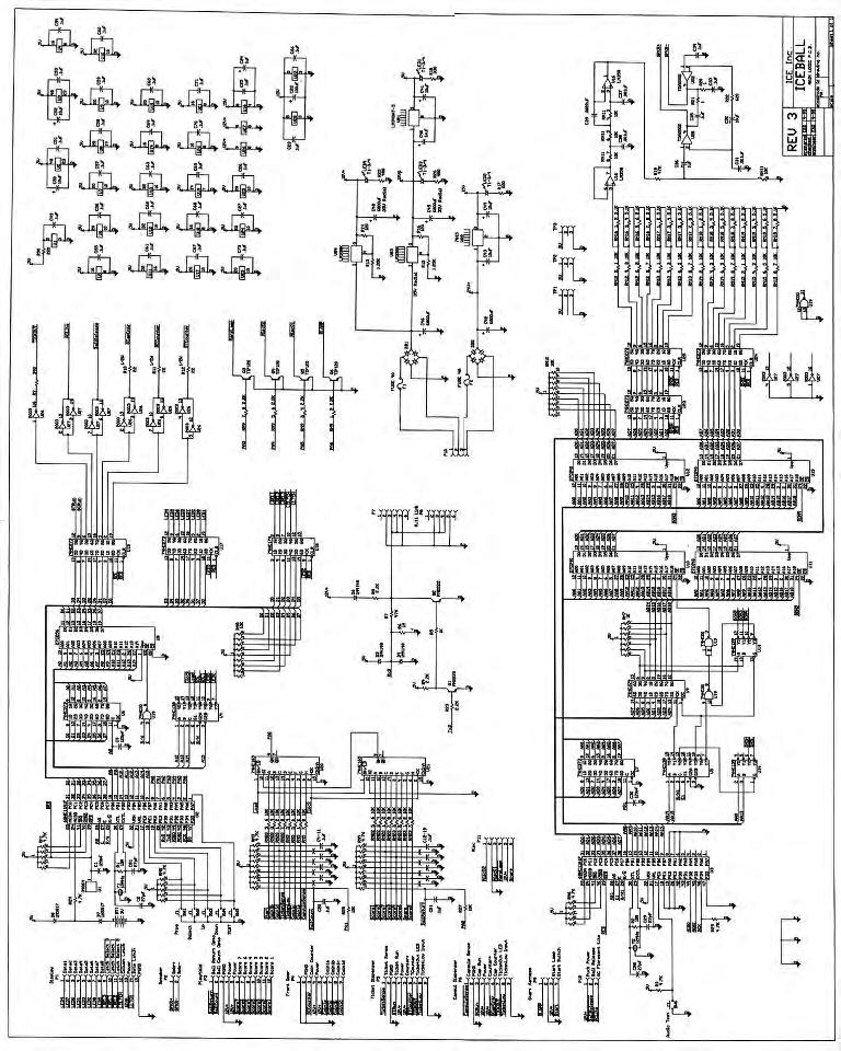
16 PARTS LISTINGS MECHANICAL PARTS GRAPHICS & DECALS AR1001 Ball Rail AR1002 Ball Return Tray AR1003 Rail Support Spacer AR1004 Ball Release Lever Spring AR1005 Cash Box AR1007 Solenoid Linkage AR1009 Ball Release Lever Bracket AR1011 Channel Cover, LEFT AR1012 Channel Cover, RIGHT AR1016 Alley Edge Protector, REAR AR1018 Ball Release Lever AR1019 Alley Edge Protector, FRONT AR1020 Cup Connecting Plates 1024 Ticket Bin 1026 Ticket Bin Switch Mounting Bracket AR1029 Speaker Grille AR1033 Cage, LEFT SIDE AR1034 Cage, RIGHT SIDE AR1035 Cage, FRONT AR2017 Diffuser Support AR3000 Runaway Material w/adhesive AR3001 Ball Jump AR3005 Ball Cover Window AR3006 Playfield Light Cover AR3008 PL7 Light Diffuser AR3010 Cup, 10,000 Point AR3011 Cup, 5,000 Point AR3012 Cup, 4,000 Point AR3013 Cup, 2,000 and 3,000 Point AR3014 Cup, 1,000 Point AR3015 Cup, Bottom Ring AR3017 Insulating Grommet AR3020 Runaway Ball Bumper Material AR3021 Ball Stop Grommet AR3024 Ball AR3065 Runaway Ball Bumper Cap, Left Side AR3066 Runaway Ball Bumper Cap, Right Side AR3069 Ball Diverter 5014 Coin Door Lock 5101 Mech Holder 6105 Latch Tool 6111 Fiber Lever Washer 6117 Clevis Pin 3/ Clevis Pin 1 AR7001 AR7002 AR7003 AR7004 AR7008 AR7009 AR7014 AR7015 AR7016 AR7017 AR7018 AR7019 AR7020 AR9001 Display Panel Programming Decal Coin Door Decal Ticket Door Decal Instruction Panel Fuse Rating Decal 10,000 Point Decal, Left Hand Side 5,000 Point Decal 4,000 Point Decal 3,000 Point Decal 2,000 Point Decal 1,000 Point Decal 10,000 Point Decal, Right Hand Side Service Manual ELECTRICAL / ELECTRONIC PARTS 211 Low Ticket Switch 248 PL7 Transformer 249 PL7 Bulb 251 PL7 Socket FP2000X Display P.C. Board AR2002 Transformer AR2005 Start Button HP2006B Blue Rotating Beacon Light AR2007 Speaker 6 X 9 AR2008 Solenoid FP2009X Optical Sensor Assembly (Zero Count) AR2009X Optical Sensor Assembly CC Ft. Computer Style Power Cord AR2028X Ball Eject P.C. Board (AR Model) AR2034X Main P.C. Board Assembly HH2050 Power Module 2111 Solid State Relay Ft. Modular Phone Cord HH5005 Ticket Dispenser (Deltronic Labs) PC20224 Counter, 12 Volt D.C. PC20429 Red Diffused L.E.D. PLEASE CALL OUR SERVICE DEPARTMENT FOR HELP WITH ANY PARTS NOT SHOWN ON THIS LIST PHONE FAX
17 17
18 Warranty I.C.E warrants all components in the ICE BALL game to be free of defects in materials and workmanship for a period of ninety days from the date of purchase. This warranty does not cover items damaged due to normal wear and tear, subjected to abuse, improperly assembled by the end user, modified, repaired, or operated in a fashion other than that described in the service manual. If your ICE BALL game fails to conform to the above-mentioned warranty, I.C.E.'s sole responsibility shall be at its option to repair or replace any defective component with a new or remanufactured component of equal to or greater O.E.M. specification. I.C.E. will assume no liability whatsoever, for costs associated with labor to replace defective parts, or travel time associated therein. I.C.E.'s obligation will be to ship free of charge, replacement parts by U.P.S. Ground, U.S. mail, or other comparable shipping means. Any express mail or overnight shipping expense is at the cost of the purchaser. Products will be covered under warranty only when: The serial number of the game with the defective parts is given. The serial number of the defective part, if applicable, is given. Defective parts are returned to I.C.E., shipping pre-paid, in a timely fashion, if requested by I.C.E. A copy of the sales receipt is available as proof of purchase upon request of I.C.E. I.C.E. distributors are independent, privately owned and operated. In their judgment, they may sell parts or accessories other than those manufactured by I.C.E. We cannot be responsible for the quality, suitability, or safety of any non-i.c.e. part, or any modification, including labor, which is performed by such a distributor. 18
OWNERS AND SERVICE MANUAL INNOVATIVE CONCEPTS IN ENTERTAINMENT INC MAIN STREET, CLARENCE, NY SERVICE: FAX:
 OWNERS AND SERVICE MANUAL INNOVATIVE CONCEPTS IN ENTERTAINMENT INC. 10123 MAIN STREET, CLARENCE, NY 14031 SERVICE: 1-716-759-0360 FAX: 1-716-759-0884 E-MAIL: service@icegame.com WEBSITE: www.icegame.com
OWNERS AND SERVICE MANUAL 2001 INNOVATIVE CONCEPTS IN ENTERTAINMENT INC.
 OWNERS AND SERVICE MANUAL 2001 INNOVATIVE CONCEPTS IN ENTERTAINMENT INC. 10123 MAIN STREET, CLARENCE, NEW YORK 14031 SERVICE 716-759-0360 SALES 716-759-0370 FAX 716-759-0390 E MAIL play@icegame.com TABLE
OWNERS AND SERVICE MANUAL INNOVATIVE CONCEPTS IN ENTERTAINMENT INC MAIN STREET, CLARENCE, NY SERVICE: FAX:
 OWNERS AND SERVICE MANUAL INNOVATIVE CONCEPTS IN ENTERTAINMENT INC. 10123 MAIN STREET, CLARENCE, NY 14031 SERVICE: 1-716-759-0360 FAX: 1-716-759-0884 E-MAIL: service@icegame.com WEBSITE: www.icegame.com
Service Manual Innovative Concepts in Entertainment
 Service Manual Innovative Concepts in Entertainment 10123 Main Street Clarence, New York 14031 (716) 759-0360 www.icegame.com Table of Contents What s included 3 Safety and Warnings 4 Game Assembly 5-9
To Purchase This Item, Visit BMI Gaming (800)
") OWNERS AND SERVICE MANUAL INNOVATIVE CONCEPTS IN ENTERTAINMENT INC. 10123 MAIN STREET, CLARENCE, NY 14031 SERVICE: 1-716-759-0360 FAX: 1-716-759-0884 E-MAIL: service@icegame.com WEBSITE: www.icegame.com
OWNERS AND SERVICE MANUAL INNOVATIVE CONCEPTS IN ENTERTAINMENT INC. 10123 MAIN STREET, CLARENCE, NY 14031 SERVICE: 1-716-759-0360 FAX: 1-716-759-0884 E-MAIL: service@icegame.com WEBSITE: www.icegame.com
EmagiKit. Privacy Pod Plus. Quiet. Easy. Affordable. INSTRUCTIONS ASSEMBLY
 EmagiKit Privacy Pod Plus Quiet. Easy. Affordable. INSTRUCTIONS ASSEMBLY DIMENSIONS AND COMPONENTS 47 47 Ceiling Unit 2-B 2-L 2-R Glass Door Corner Trim Door Handle 90 Adjustable Height Work Surface 1-B
VARIABLE SPEED BECH LATHE
 VARIABLE SPEED BECH LATHE Instruction Manual Please read this instruction manual thoroughly and follow all directions carefully. 1 Important Safety Instructions READ ALL INSTRUCTIONS AND WATNINGS BEFORE
TABLE OF CONTENTS TABLE OF CONTENTS
 NBA Jr. Basket Ball OWNERS AND SERVICE MANUAL INNOVATIVE CONCEPTS IN ENTERTAINMENT INC. 0 MAIN STREET, CLARENCE, NY 0 SERVICE: -7-79-00 FAX: -7-79-088 E-MAIL: service@icegame.com WEBSITE: www.icegame.com
OPERATOR'S MANUAL ROUTER MOUNTING KIT
 OPERATOR'S MANUAL MOUNTING KIT 4950301 (FOR USE WITH BT3000 AND BT3100 TABLE SAWS) Your new router mounting kit has been engineered and manufactured to Ryobi's high standard for dependability, ease of
PORTA~TRACE. GAGNE, INC. 41 Commercial Dr. Johnson City, New York Phone: Fax: ASSEMBLY INSTRUCTIONS
 PORTA~TRACE GAGNE, INC. 41 Commercial Dr. Johnson City, New York 13790 Phone: 1-607-729-3366 Fax: 1-607-729-7644 ASSEMBLY INSTRUCTIONS PORTA~TRACE MODEL 2436T LIGHT TABLE PORTA~TRACE MODEL 3648T LIGHT
impact VC-500LR Monolight INSTRUCTIONS
 impact lighting equipment and accessories VC-500LR Monolight INSTRUCTIONS Congratulations on your purchase of the Impact VC-500LR Monolight. We feel that it will contribute much to your photographic skill
Standard PS-P61 Punch Stapler
 Standard PS-P61 Punch Stapler Instruction Manual Provided By http://www.mybinding.com http://www.mybindingblog.com PUNCH STAPLE PS-P61 Important Information - This manual is designed to help you to install,
Riverside. Windward Bay EntertaInment Wall System Assembly Instructions. Made In Viet Nam. Right Pier. Bridge & Back Panel.
 EntertaInment Wall System Page 1 of 12 Product No. 42840 42848 42849 42843 Product Description Console Left Pier Right Pier Bridge & Back Panel Right Pier Bridge & Back Panel Left Pier 63" Inch Ent. Console
Puppy Jump Operations Manual
 Puppy Jump Operations Manual WARNING Be sure to read this Operation Manual before using your machine to ensure safe operation. 2013 Bob s Space Racers Incorporated 427 15 th Street, Daytona Beach, Florida
TABLE OF CONTENTS DESCRIPTION. Safety Instructions Assembly Operation... 7
 TABLE OF CONTENTS DESCRIPTION PAGE Warranty... 1 Safety Instructions... 2 Assembly... 3 Operation... 7 #360 Grain Cleaner Drawings... 8 #360 Grain Cleaner Parts List... 10 Utility Auger Option Drawing...
PLEASE READ ALL INSTRUCTIONS BEFORE OPERATING THIS MACHINE
 PLEASE READ ALL INSTRUCTIONS BEFORE OPERATING THIS MACHINE TRIGGER HAPPY IS AN EXCITING NEW SHOOTING GALLERY GUN GAME FROM FUN INDUSTRIES. THIS MACHINE IS DESIGNED TO DISPENSE 2 PRIZES AS WELL AS TICKET
Mechanical Frappe Press
 Mechanical Frappe Press Operation Manual CONTENTS OPERATIONAL INSTRUCTIONS PRECAUTIONS PART NAMES INCLUDED ITEMS BASIC OPERATION MAINTENANCE REPLACEMENT PARTS Thank you for using The Frapptastic Five Mechanical
ASPEN OUTDOOR TABLE TENNIS
 ASPEN OUTDOOR TABLE TENNIS Replacement Parts Order direct at or call our Customer Service department at (800) 225-7593 8 am to :30 pm Central Standard Time January 201 UPC Code 7-19265-51830-3 Staple your
HOLE CUTTER SHARPENER ASSEMBLY & SERVICE MANUAL
 HOLE CUTTER SHARPENER ASSEMBLY & SERVICE MANUAL WARNING You must thoroughly read and understand this manual before operating the equipment, paying particular attention to the Warning & Safety instructions.
YES 12 Charging Wall Cabinet for Mini-laptops
 Built with Anthro-DNA Owner's Manual for YES 12 Charging Wall Cabinet for Mini-laptops Part # YESMLCGMPW Components at a Glance 7 1 9 8 2 4 5 11 6 10 3 Front of Cabinet (closed) 1. Locking front door to
3-1/4 HP VARIABLE SPEED PLUNGE ROUTER
 IMPORTANT INFORMATION 2-YEAR LIMITED WARRANTY FOR THIS PLUNGE ROUTER KING CANADA TOOLS OFFERS A 2-YEAR LIMITED WARANTY FOR NON-COMMERCIAL USE. 3-1/4 HP VARIABLE SPEED PLUNGE ROUTER PROOF OF PURCHASE Please
Installation Manual Porter Road, Sarasota FL fax
 072015 Installation Manual BEFORE YOU BEGIN: Read these instructions completely and carefully. FOR YOUR SAFETY: Read and observe all CAUTIONS and WARNINGS shown throughout these instructions. Risk of injury.
Installation, Usage and Maintenance Guide
 Installation, Usage and Maintenance Guide October 2012 WARNING Read this document before installing or using Johnny Mnemonic Topper Mod by Pinballtoppers Improper installation, improper use, may cause
OVER THE RANGE MICROWAVE OVEN INSTALLATION INSTRUCTIONS
 OVER THE RANGE MICROWAVE OVEN INSTALLATION INSTRUCTIONS Please read and save these installation instructions. MODEL NO.: DOTR12CWIV/DOTR12CBIV P/N: 3828W5U0202 YOUR SAFETY FIRST Read this entire manual
Please read BOTH these Installation Instructions and the General Instructions prior to installing or operating this equipment.
 Attachment Tab Height: 24-3/4 Attachment Tab Width: 21 Serial Number Please read BOTH these and the General Instructions prior to installing or operating this equipment. 1. Blue Ox towing products and
KN-8828B Upgrade Directions
 KN-8828B Upgrade Directions This document outlines the steps to take to update earlier Hottop Bean Roasters to the KN-8828B 2007 by Chang Yue and Hottop USA - All Rights Reserved No part of this document
DUMP N GO MODEL PV 212 JOHN DEERE
 DUMP N GO MODEL PV 212 JOHN DEERE 8722 E Research Center Rd. New Hope, MN 55428 Ph: 763-535-4038 Fax: 763-535-4633 PV 212 shown on John Deere Model X500 Fits models: LX/GT and GX ASSEMBLY INSTRUCTIONS
MODEL 83 Pail Handler
 MORSE MFG. CO., INC. 727 West Manlius Street P.O. Box 518 East Syracuse, NY 13057-0518 Phone: 315-437-8475 Fax: 315-437-1029 Email: service@morsemfgco.com Website: www.morsemfgco.com COPYRIGHT 2005 MORSE
DUMP N GO MODEL PV 212 FERRIS
 DUMP N GO MODEL PV 212 FERRIS 8722 E Research Center Rd. New Hope, MN 55128 Ph: 763-535-4038 Fax: 763-535-4633 PV 212 shown on Ferris IS1500Z Fits Ferris Zero-Turn mower models: IS500Z, IS1500Z, IS2000Z,
Installation & User Guide. For Powering Distributed Audio Systems A45-X2 TWO CHANNEL AMPLIFIER
 Installation & User Guide For Powering Distributed Audio Systems TWO CHANNEL AMPLIFIER A45-X2 A45-X2 TWO CHANNEL AMPLIFIER TABLE OF CONTENTS Features...1 Product Overview...2 Package Contents...4 Preparing
PLEASE NOTE: LAI Games
 PLEASE NOTE: Read this manual BEFORE operating the machine. Keep this manual for your reference. Go to www.laigames.com click on Operator Access to register your games and receive of future updates. LAI
POCKEY 3 IN 1 GAME TABLE
 POCKEY 3 IN 1 GAME TABLE Replacement Parts Order direct at or call our Customer Service department at (800) 225-7593 8 am to 4:30 pm Central Standard Time Publication 64-1046 Rev C October 2014 UPC Code
LEG CURL IP-S1315 INSTALLATION INSTRUCTIONS
 LEG CURL IP-S35 INSTALLATION INSTRUCTIONS Copyright 2009. Star Trac by Unisen, Inc. All rights reserved, including those to reproduce this book or parts thereof in any form without first obtaining written
Dual Arm Tilt LCD Mount
 Installation Manual model # 51324 M o u n t i n g S y s t e m s Dual Arm Tilt LCD Mount Fits Displays 13 to 32 Supports Up to 50 lbs (23 kgs) Projection from Wall from 3 to 17 Meets VESA Standards 50/75/100,
OPERATOR'S MANUAL RULES FOR SAFE OPERATION
 OPERATOR'S MANUAL #4950300 ROUTER AND JIG SAW MOUNTING KIT (FOR USE WITH THE BT3000 TABLE SAW) CONGRATULATIONS AND THANK YOU FOR BUYING THIS RYOBI ROUTER AND JIG SAW MOUNTING KIT. Your new #4950300 Router
PULL-THRU USER S MANUAL
 PULL-THRU USER S MANUAL G14x Part # 310 120 177 G20 Part # 310 120 188 G20x Part # 310 120 186 G40x Part # 310 120 163 TABLE OF CONTENTS SECTION 1 PCB DESIGN AND MOUNTING SECTION 2 MOUNTING ADAPTER TO
To Purchase This Item, Visit BMI Gaming (800)
") OWNERS AND SERVICE MANUAL INNOVATIVE CONCEPTS IN ENTERTAINMENT INC. 10123 MAIN STREET, CLARENCE, NY 14031 SERVICE: 1-716-759-0360 FAX: 1-716-759-0884 E-MAIL: service@icegame.com WEBSITE: www.icegame.com
OWNERS AND SERVICE MANUAL INNOVATIVE CONCEPTS IN ENTERTAINMENT INC. 10123 MAIN STREET, CLARENCE, NY 14031 SERVICE: 1-716-759-0360 FAX: 1-716-759-0884 E-MAIL: service@icegame.com WEBSITE: www.icegame.com
TRAKFAST REPAIR MANUAL DANGER TOOL DISASSEMBLY ALWAYS TAKE THE FOLLOWING PRECAUTIONS BEFORE ANY SERVICE OR ROUTING MAINTENANCE IS PERFORMED:
 DANGER ALWAYS TAKE THE FOLLOWING PRECAUTIONS BEFORE ANY SERVICE OR ROUTING MAINTENANCE IS PERFORMED: REMOVE FASTENERS REMOVE FUEL CELL REMOVE BATTERY REMOVE THE MAGAZINE ASSEMBLY Loosen and remove knob
OWNERS AND SERVICE MANUAL INNOVATIVE CONCEPTS IN ENTERTAINMENT INC MAIN STREET, CLARENCE, NY SERVICE: FAX:
 OWNERS AND SERVICE MANUAL INNOVATIVE CONCEPTS IN ENTERTAINMENT INC. 10123 MAIN STREET, CLARENCE, NY 14031 SERVICE: 1-716-759-0360 FAX: 1-716-759-0884 E-MAIL: service@icegame.com WEBSITE: www.icegame.com
STRINGING MACHINE OWNER'S MANUAL. Copyright 1998 GAMMA Sports - All Rights Reserved
 6002 STRINGING MACHINE OWNER'S MANUAL Issue 3 - June 20, 1998 Copyright 1998 GAMMA Sports - All Rights Reserved 6002 OWNER'S MANUAL TABLE OF CONTENTS PAGE 1... WARRANTY PAGE 2... FEATURES PAGE 3... ASSEMBLY
INSTALLATION INSTRUCTIONS HEAVY DUTY TILT WALL MOUNT Model: PPH-2000
 INSTALLATION INSTRUCTIONS HEAVY DUTY TILT WALL MOUNT Model: PPH-2000 Specifications: Accomodates Akira and Orion 84" displays without interface bracket; accomodates other large flat panel displays with
Yes 20 Charging Wall Cabinet for Tablets
 Built with Anthro-DNA Owner's Manual for Yes 20 Charging Wall Cabinet for Tablets Part # YESCABGMPW Components at a Glance 1 2 4 5 8 7 10 Front of Cabinet (closed) 1. Locking front door to User area. 2.
Heritage Solar Lamp Post
 Heritage Solar Lamp Post Instruction Manual 23108 Thank you very much for choosing a Nature Power product! For future reference, please complete the owner s record below: Model: Purchase Date: Save the
EllisSaw.com. EllisSaw.com P.O. Box Verona, WI
 P.O. Box 9019 Verona, WI 9-019 GENERAL OPERATING & SAFETY INSTRUCTIONS * READ INSTRUCTIONS BEFORE USE * CAUTION: Disconnect power supply cord from power source when doing repair work or changing belt.
LC6X4WTM Security Wall Mount with Tilt for up to 60" Flat Screens with VESA 600mm x 400mm or less
 Page 1 of 6 The LC6X4WTM Security Wall Mount with Tilt is designed to secure a flat screen, up to a 60", to the wall while still allowing the monitor to tilt. The VESA mounting patterns on the front of
INSTALLATION GUIDE MICROWAVE OVEN UPMC3084ST. MFL _00
 INSTALLATION GUIDE MICROWAVE OVEN UPMC3084ST MFL06208710_00 www.thesignaturekitchen.com YOUR SAFETY FIRST BEFORE YOU START Proper installation is the installer's responsibility! Proper installation by
MODEL SETUP & OPERATION MANUAL DOVETAIL JIG FEATURES SPECIFICATIONS
 SETUP & OPERATION MANUAL FEATURES Male and female dovetail joints are cut simultaneously, to ensure perfectly matched dovetail joints. Side stops provided, allow repeated precise dovetail joint cutting
INSTALLATION INSTRUCTIONS
 Sheet 1 of 5 General: Upon receipt of fixture thoroughly inspect for any freight damage, which should be brought to the attention of the delivery carrier. Compare the catalog description listed on the
For More Product Information On This Other Arcade and Amusment Products, Visit :
 OWNERS AND SERVICE MANUAL INNOVATIVE CONCEPTS IN ENTERTAINMENT INC. 10123 MAIN STREET, CLARENCE, NY 14031 SERVICE: 1-716-759-0360 FAX: 1-716-759-0884 E-MAIL: service@icegame.com WEBSITE: www.icegame.com
INSTALLATION INSTRUCTIONS
 INSTALLATION INSTRUCTIONS SPORTSMAN WINCH MOUNT GRILLE GUARD APPLICATION: 2016-2018 Toyota Tacoma PART NUMBER: 40-93885, 45-93880, 46-23885 ITEM QUANTITY DESCRIPTION TOOLS NEEDED 1 1 WINCH TRAY 15MM SOCKET
Installation Instructions
 For Medium (15-18.5K) + Heavy duty (22-28.5K) Air Conditioner READ BEFORE INSTALLING UNIT To avoid risk of personal injury, property damage, or product damage due to the weight of this device and sharp
OWNERS AND SERVICE MANUAL INNOVATIVE CONCEPTS IN ENTERTAINMENT INC MAIN STREET, CLARENCE, NY SERVICE: FAX:
 OWNERS AND SERVICE MANUAL INNOVATIVE CONCEPTS IN ENTERTAINMENT INC. 10123 MAIN STREET, CLARENCE, NY 14031 SERVICE: 1-716-759-0360 FAX: 1-716-759-0884 E-MAIL: service@icegame.com WEBSITE: www.icegame.com
FISHIN HOLE GAME MANUAL Rev. A
 FISHIN HOLE GAME MANUAL Rev. A WARNING Be sure to read this Operation Manual before using your machine to ensure safe operation. 2013 Bob s Space Racers Incorporated 427 15 th Street, Daytona Beach, Florida
BMW E39/E53 Android Touch Screen Radio Installation Instructions
 BMW E9/E5 Android Touch Screen Radio Installation Instructions Enjoy your new Android Radio from Bremmen Parts, we appreciate your business. Vibrant Touch Display This radio features a responsive 9 touch
Manual Carton Closing Staplers
 Operator s Manual Manual Carton Closing Staplers SHB00-A Item No. 6400 -/8" Crown Carton Closing Stapler 5/8" and /4" (5mm and 8mm) Ask for Genuine INTERCHANGE A58 and A4 Staples SHB50-C Item No. 640 -/4"
SERIES M MIXER MASTS
 SERIES M MIXER MASTS T AB L E O F C O N T E N T S V e n d o r D a t a Material Data Sheet 4-in. Mixer Mast Specification 3-in. Mixer Mast Specification 2 - in. M i x e r M a s t S p e c i f i c a t i o
TIRADE MMXI SOCCER TABLE
 TIRADE MMXI SOCCER TABLE Replacement Parts Order direct at or call our Customer Service department at (800) 225-7593 8 am to 4:30 pm Central Standard Time Publication 64-0908 Rev D August 2014 UPC Code
LifeGear G1 /HOME GYM ITEM NO.: 63100
 LifeGear G1 /HOME GYM ITEM NO.: 63100 OWNER S MANUAL IMPORTANT: Read all instructions carefully before using this product. Retain this owner s manual for future reference. The specifications of this product
Operating Instructions and Parts Manual SLT-1100 Jumbo Scissor Lift Table
 Operating Instructions and Parts Manual SLT-1100 Jumbo Scissor Lift Table JET 427 New Sanford Road LaVergne, Tennessee 37086 Part No. M-140780 Ph.: 800-274-6848 Revision B1 05/2014 www.jettools.com Copyright
INSTRUCTION MANUAL LKG 601 Electrical Safety Analyzer
 INSTRUCTION MANUAL LKG 601 Electrical Safety Analyzer 110 Toledo Street Farmingdale, NY 11735 USA http://www.netech.org 510-USER-Manual Rev3 10/29/2007 Dear User, We appreciate your purchase of the LKG
Installing the Quilter s Cruise Control TM. Cruising with the Quilter s Cruise Control TM
 TM User s Manual This user s manual is for the Quilter s Cruise Control TM with Optical Encoders, and will help you install your unit on your short-arm quilting frame system properly. Installing the Quilter
INSTRUCTION BOOKLET AND WARRANTY INFORMATION 6 BENCH GRINDER
 INSTRUCTION BOOKLET AND WARRANTY INFORMATION 6 BENCH GRINDER Part No.: SW1250 PLEASE READ CARE AND SAFETY INSTRUCTIONS BEFORE USE SPECIFICATIONS Part No.: SW1250 Input Voltage: 240V Frequency: 50Hz Rated
TABLE OF CONTENTS DESCRIPTION. Safety Instructions Assembly Operation... 7
 TABLE OF CONTENTS DESCRIPTION PAGE Warranty... 1 Safety Instructions... 2 Assembly... 3 Operation... 7 #360 Grain Cleaner Drawings... 8 #360 Grain Cleaner Parts List... 10 Utility Auger Option Drawing...
SERVICE MANUAL PARTS LIST MODEL: NH40
 SERVICE MANUAL & PARTS LIST MODEL: NH40 CONTENTS What to do when... 1-3 SERVICE ACCESS Face Cover... 4 Bed Cover... 5 Free-arm Cover... 6 Front Cover... 7 Rear Cover... 8 MECHANICAL ADJUSTMENT Presser
С 800 CASSIDA C 800 HIGH SPEED COIN COUNTER
 С 800 CASSIDA C 800 HIGH SPEED COIN COUNTER This manual contains important information on safety measures and operational features. Please read it carefully before operating your coin counter, and keep
Interactive Monitor Arm
 Interactive Monitor Arm Tools Required -5mm Allen wrench -Phillips screwdriver -Plastic mallet There are two ways to attach a Monitor Arm to a Full Frame; with a Beam, or with a Post Mount. Both methods
FD 2002IL AutoSeal System
 FD 2002IL AutoSeal System 4/2017 OPERATOR MANUAL FIRST EDITION TABLE OF CONTENTS DESCRIPTION 1 SPECIFICATIONS 1 UNPACKING 1 SETUP 2 Sealer Alignment Base Setup 2 Sealer Setup 2-4 Printer Alignment Base
Models 2230 and 2240
 Models 2230 and 2240 Overview... 2 Tools Needed... 2 Hardware...3 Assembly... 4-13 Installation... 14 Drawer Removal... 15 Operation... 15 Maintenance... 15 Accessories... 16 Limited Warranty... 16 Perform
Allegro Home Office Assembly Instructions. Tipping Restraint. Bun Foot W/ Leveler. 4 pcs.
 email: info@riverside-furniture.com Allegro Home Office Assembly Instructions Components and Hardware List Page 1 of 5 Made in China Shelf Pin Wood Shelf File Rod & Clips 1/2"Wood Screw A 16 pcs. B 4 pcs.
Mighty Mo GX Series Cabinet Installation Guide. OR Rev /11
 Mighty Mo GX Series Cabinet Installation Guide OR-71601787 Safety and Warning ATTENTION The exclamation point within an equilateral triangle is intended to alert the user to the presence of important operating
Hatchback Wing Riser Kit
 Hatchback Wing Riser Kit 2015-06-11 Thank you for purchasing this PERRIN product for your car! Installation of this product should only be performed by persons experienced with installation of aftermarket
SawStop. Contractor Fence Assembly OWNER S MANUAL. Model CNS-SFA
 Contractor Fence Assembly OWNER S MANUAL Model CNS-SFA Warranty warrants to the original retail purchaser of the Contractor Fence Assembly accompanying this manual that the fence assembly will be free
Removing and Replacing the Y-truck
 Service Documentation Removing and Replacing the Y-truck To remove and replace the Y-truck you will need the following tools: 4mm Allen wrench 12mm stamped flat wrench #2 Phillips screwdriver (magnetic
AUDI A8 D3 REPLACING THE OUTSIDE DRIVER DOOR HANDLE
 AUDI A8 D3 REPLACING THE OUTSIDE DRIVER DOOR HANDLE The keyless entry system in the D3 is a great feature. If you have the car key fob in your pocket, putting your hand under the door handle will unlock
16 STEEL CABINET HEAVY DUTY
 HEAVY DUTY 16 STEEL CABINET ASSEMBLY INSTRUCTIONS SIX DRAWER BASE CABINET 12-2013 Parts List Part No Description Qty Image SIX DRAWER BASE CABINET Part No Description Qty Image SB-1 Cabinet Body 1 SLD-01
compile system INSTALLATION GUIDE Updated January 2019
 INSTALLATION GUIDE Updated January 09 compile system Table of Contents Panels 0 Quick Connect Clips 0 Lock Clips 0 Panel Trims 0 Privacy Glass 0 Post Base Covers 04 Electrical 04 Power Distribution Harness
Household Appliances. Over-the-Range Microwave. Installation Instructions. For Models: HMV9302, HMV9305, HMV9306, HMV9307
 Over-the-Range Microwave Household Appliances Installation Instructions For Models: HMV9302, HMV9305, HMV9306, HMV9307 PLEASE READ ENTIRE INSTRUCTIONS BEFORE PROCEEDING IMPORTANT: Save these instructions
APES HD-7700 Version Operator s Training Manual
 APES-14-77 HD-7700 Version Operator s Training Manual Issue A1 09/03 P/N 900599 Performance Design Inc. 2350 East Braniff St. Boise Idaho 83716 This manual contains very important safety information and
PLEASE NOTE: Preliminary. LAI Games
 Preliminary PLEASE NOTE: Read this manual BEFORE operating the machine. Keep this manual for your reference. Go to www.laigames.com click on Support to register your games and receive of future updates.
31082 INSTALLATION INSTRUCTIONS
 08 INSTALLATION INSTRUCTIONS Safety glasses should be worn at all times while installing this product. YEARS: 07-CURRENT MAKE: HONDA MODEL: RIDGELINE STYLE: TRUCK WARNING: NEVER EXCEED YOUR VEHICLE MANUFACTURER'S
ABOUT SMOKIN' TOKEN EXTREME
 ABOUT SMOKIN' TOKEN EXTREME Operators distinguish Smokin Token as one of the great redemption success stories, and are now able to share in that unprecedented success for yet another generation. Smokin
8' HOT SHOT SKEEBALL TABLE ASSEMBLY INSTRUCTIONS
 8' HOT SHOT SKEEBALL TABLE ASSEMBLY INSTRUCTIONS NG2015 THANK YOU! Thank you for purchasing this product. We work around the clock and around the globe to ensure that our products maintain the highest
!ATTENTION: READ BEFORE ASSEMBLING/OPERATING! ASSEMBLY INSTRUCTIONS FOR THE MULTICHAIR 6000Tilt Series
 !ATTENTION: READ BEFORE ASSEMBLING/OPERATING! ASSEMBLY INSTRUCTIONS FOR THE MULTICHAIR 6000Tilt Series multichair 6000Tilt multichair 6200Tilt multichair 6000Tilt P1 multichair 6000Tilt P2!ATTENTION: READ
Print Head Installation Guide
 Print Head Installation Guide MCS Raptor 6 (MCS Eagle AMS Software) is copyright of MCS Incorporated. 2015 MCS Incorporated. 1 Contents Tools... 4 Warnings... 4 Introduction... 4 Section One - Pillar Installation...
Mercer Crib (M6801)- Assembly and Operation Manual
- Assembly and Operation Manual") Mercer Crib (M6801)- Assembly and Operation Manual Congratulations on purchasing this product. This crib will provide many years of service if you adhere to the following guidelines for assembly, maintenance,
Mercer Crib (M6801)- Assembly and Operation Manual Congratulations on purchasing this product. This crib will provide many years of service if you adhere to the following guidelines for assembly, maintenance,
Elimination of Elevator Bounce
 For the Agilent Archon Autosampler Rework Instructions CAUTION This kit is intended for use by Agilent Service personnel only. Elevator Removal 1 Open top cover. 2 Open front lower door. 3 Remove vial
Installation Operation Care
 Installation Operation Care Designer Roller and Designer Screen Shades Standard and Cassette Cordless Lifting System CONTENTS Getting Started: Product Views... 1 Tools and Fasteners Needed... 3 Installation
Mirage Installation Manual
 Mirage Installation Manual General Information This installation manual provides necessary information for the safe installation of the Mirage product. WARNING: Failure to follow the instructions in this
SawStop. T-GlideTM. Fence System- Professional Series II OWNER S MANUAL
 SawStop T-GlideTM Fence System- Professional Series II OWNER S MANUAL Warranty SawStop warrants to the original retail purchaser of a new T-Glide Fence System - Professional Series II from an authorized
Hardware and Components:
 Hardware and Components: (A) 4X 5/16 x 1 Carriage Bolt (B) 2X 5/16 x 2-1/4 Carriage Bolt (C) 2X 5/16 x 3-1/4 Hex Bolt (D) 2X 5/16 x 3/4 Hex Bolt (E) 2X 5/16 x 1-1/4 Hex Bolt (F) 5/16 x 2-1/4 Hex Bolt (G)
Top Innovations, Inc. Innovative Products to Make Your Life Easier. Model SP-402 Owner s Manual
 Top Innovations, Inc. Innovative Products to Make Your Life Easier Model SP-402 Owner s Manual THIS IS NOT A TOY! Adult supervision recommended Item contains sharp functional points and small parts Machine
Sunset Swings By Health in Motion, LLC
 Sunset Swings By Health in Motion, LLC Model 421 Lounge Swing Assembly and Operation Manual Record Serial Number Here www.sunsetswings.com by Health In Motion, LLC. 11/6/2009 421 Owners Assembly and Operation
Tilting Flat Panel Wall Mount Installation Guide
 Tilting Flat Panel Wall Mount Installation Guide Model: A580TM Easy installation Built-in level for easy positioning Safety bolts lock the TV on the mount Easy to adjust tilt angles: +5 to -15 degrees
BIFOLD FUTON FRAME TRINITY ARM. Seat Rails and Slats x 1. *Note: Use 4pc of 100mm Bolts and 4pc of 60mm Bolts to attach the arms to the Stretchers.
 1A Parts in this box. 2pc with extra holes 2pc with extra holes & plastic stoppers Arms x 2 Back Rails and Slats x 1 Full Size: Slat Supports x 6 3pc are longer for the Back deck Back Side Rails x 2 Seat
4-Piece Table Tennis Table
 Item# 45-6074 4-Piece Table Tennis Table Please keep this instruction manual for future reference If you have any problems with your new product, please contact Triumph Sports USA at 1-866-815-4173, or
User Manual. Where Imagination Meets Innovation. FRESH AERO Easy Seat Tool For Grumman AA1 & AA5 Series Aircraft
 FRESH AERO Easy Seat Tool For Grumman AA1 & AA5 Series Aircraft Alpha Model For Grumman AA-1 & AA-5 Series Aircraft with Access Holes in Front Seat Buckets User Manual The Steelebrook Group Where Imagination
MODEL SETUP & OPERATION MANUAL DOVETAIL JIG FEATURES
 SETUP & OPERATION MANUAL FEATURES New clamping system for greater accuracy. Lockable template height for a stable platform for the router. Cuts precision matching dovetails with the same accuracy found
The Bowflex Revolution XP Home Gym Assembly Instructions. P/N: Rev ( /0 )
") P/N: 001-7057 Rev ( /0 ) The Bowflex Revolution XP Home Gym Assembly Instructions 2 Table of Contents Before You Start... 2 Tools You Will Need / Hardware Contents... 3 Box Contents... 6 Assembling Your
P/N: 001-7057 Rev ( /0 ) The Bowflex Revolution XP Home Gym Assembly Instructions 2 Table of Contents Before You Start... 2 Tools You Will Need / Hardware Contents... 3 Box Contents... 6 Assembling Your
Transit Connect Full/Half Installation Instructions
 GATHER THESE TOOLS FOR ASSEMBLY & INSTALLATION 7/16 wrench, T45 Torx socket, 7/16 socket, 3/8 drive ratchet - 3/8 socket One 1/8 square end driver bit provided - Electric drill/driver/18v cordless One
Installation, Usage and Maintenance Guide. October Install for Typical speaker style...page 3
 Installation, Usage and Maintenance Guide October 2013 Install for Typical speaker style...page 3 Install for Round speaker style (Star Trek)...Page 6 1 WARNING Improper installation, improper use, may