PLEASE NOTE: Version LAI Games
|
|
|
- Mark Newman
- 6 years ago
- Views:
Transcription


1 Version PLEASE NOTE: Read this manual BEFORE operating the machine. Keep this manual for your reference. Go to Click on Support to register your Game and receive future updates. LAI Games
2 TABLE OF CONTENTS SAFETY PRECAUTIONS...1 MACHINE INSTALLATION AND INSPECTION...2 INTRODUCTION...3 SPECIFICATIONS...4 ASSEMBLY INSTRUCTION...5 TICKET TO CAPSULE CONVERSION...14 CAPSULE CONVERSION 3 SIZE (OPTIONAL) TO 2 CAPSULE DIPENSER ADAPTER (OPTIONAL)...16 HOW TO PLAY...17 PLAYERS AIM TO BUILD A VERTICAL STACK OF BLOCKS...17 FITTING PRIZES IN PRIZE COMPARTMENTS...18 PRIZE SELECTION AND PAYOUT ADJUSTMENT...19 OPERATION...21 OPERATIONAL DIAGRAM...21 ATTRACT MODE...21 PLAY MODE...21 TEST MODE...22 TEST MODE DIAGRAM...22 SOUND, LAMPS & DISPLAY TEST...23 SWITCH TEST...23 RUN TEST (TICKET/CAPSULE DISPENSER MOTOR)...24 PROGRAMMABLE ADJUSTMENTS MODE...25 PROGRAMMABLE ADJUSTMENTS MODE DIAGRAM...25 PROGRAMMABLE ADJUSTMENTS PROCEDURE...25 PROGRAMMABLE ADJUSTMENTS QUICK REFERENCE TABLE V PROGRAMMABLE ADJUSTMENTS DETAILED...27 AUDITS MODE...34 AUDITS MODE DIAGRAM...34 AUDIT PROCEDURE...35 AUDITS QUICK REFERENCE TABLE...36 AUDITS DETAILED...37 GAME HISTORY MODE...40 GAME HISTORY MODE DIAGRAM...40 ii
3 GAME HISTORY PROCEDURE...40 GAME HISTORY QUICK REFERENCE TABLE...41 ERRORS AND TROUBLESHOOTING...42 ERROR CODE QUICK REFERENCE TABLE...42 TROUBLESHOOTING GAME ERRORS...43 SECTION A: SERVICE INSTRUCTIONS...45 LOCATING AND ACCESSING PARTS...46 PARTS LOCATION DIAGRAM...46 PARTS LOCATION DIAGRAM...47 PARTS LOCATION DIAGRAM...48 PARTS LOCATION DIAGRAM...49 LAMPS...50 MAINTENANCE...51 BASE EXPLODED VIEW...52 SECTION B: TECHNICAL DETAILS...53 LOCKING MECHANISM EXPLODED VIEW...54 MAINS VOLTAGE ADJUSTMENT...55 COIN OPTIONS REFERENCE GUIDE...56 TICKET DISPENSER REFERENCE GUIDE...57 CONNECTION INFORMATION D PART EXPLODE VIEW...63 MEGA STACKER MAIN WIRING MEGA STACKER MAIN WIRING MEGA STACKER CONTROL WIRING MEGA STACKER CONTROL WIRING MEGA STACKER POWER WIRING MEGA STACKER POWER WIRING MEGA STACKER POWER WIRING MEGA STACKER OPTIONAL WIRING...76 iii
4 SAFETY PRECAUTIONS The following safety precautions and advisories are used throughout this manual and are defined as follows. * WARNING! * Disregarding this text could result in serious injury. * CAUTION! * Disregarding this text could result in damage to the machine. * NOTE! * An advisory text to hint or help understanding. BE SURE TO READ THE FOLLOWING * WARNING! * Always Turn OFF Mains AC power and unplug the game, before opening or replacing any parts. Always When unplugging the game from an electrical outlet, grasp the plug, not the line cord. Always Connect the Game Cabinet to grounded electrical outlet with a securely connected ground line. Do Not Install the Game Cabinet outdoors or in areas of high humidity, direct water contact, dust, high heat or extreme cold. Do Not Install the Game Cabinet in areas that would present an obstacle in case of an emergency, i.e. near fire equipment or emergency exits. * CAUTION! * Always Use a Digital Multi meter, logic tester or oscilloscope for testing integrated circuit (IC) logic PC boards. The use of a continuity tester is not permitted. Do Not Connect or disconnect any of the integrated circuit (IC) logic PC boards while the power is ON. Do Not Use any fuse that does not meet the specified rating. Do Not Subject the game cabinet to extreme temperature variations. Reliability of electrical components deteriorates rapidly over 60 o C. Page 1
5 MACHINE INSTALLATION and INSPECTION When installing and inspecting Mega Stacker, be very careful of the following points and pay attention to ensure that the players can enjoy the game safely. Be sure to turn the power OFF before working on the machine. * WARNING! * Always Turn OFF mains power before removing safety covers and refit all safety covers when work is completed. Make sure the power cord is not exposed on the surface (floor, ground, etc.) where people walk. Check that the rubber glide feet levelers are set correctly on the floor so that the game cabinet is level and stable. Always make complete connections for the integrated circuit (IC) logic PC Boards and other connectors. Insufficient insertion can damage the electrical components. * CAUTION! * Before Switching the machine on be sure to check that it has been set on the correct voltage for your area! Refer To the mains voltage adjustment section of this manual. Machines are normally shipped on 220V AC unless otherwise specified. Only qualified personnel should inspect or test the integrated circuit (IC) logic PC Boards. If any integrated circuit (IC) logic PC Boards should need servicing. Please contact the nearest LAI Games Distributor. (Refer to the back page of this manual) Page 2
6 INTRODUCTION CONGRATULTIONS! Your Mega Stacker is a great centre piece game with a large bright and attractive display panel. The spacious prize compartments will illuminate your prizes which makes them stand out to the customer. It also has dynamic sound effects with a powerful subwoofer for that great game experience. Another great product from LAI Games. We hope you take the time to read this manual and learn about the many features and user friendly adjustments that can be made to fine-tune the game for maximum earning potential. DESCRIPTION Mega Stacker is a quick skill game that is simple to learn and fast to play. The player uses the start/stop button to stop the moving blocks on top of the blocks in the previous level. Each level higher the blocks are stacked the game will get progressively harder. Once the player reaches the Ticket Level, they can collect the Tickets or continue to play on for the Major Prize but if they lose, they get nothing unless the Mercy Prize option has been activated. Most players who reach the Ticket Level will continue to play for the Major Prize believing they can reach it easily. PACKAGING At delivery, the machine should arrive in good condition. To move the packaged machine for transport or placement, use a forklift and take care not to hit the package or stack heavy objects on top, as this may cause damage to the machine. CONTENTS The Mega Stacker cabinet Keys: 2 x coin door keys 2 x back door keys 2 x ticket door key Operator s manual IEC Power Cord (In cash box) Parts & Accessories (In cash box) Page 3
7 DIMENSIONS Operator's Manual Mega Stacker SPECIFICATIONS Weight : 490 kg (1080.3lb) Height : 2930 mm (115.4 ) Width : 2510mm (99 ) Length : 1770mm (70 ) Power : 792 Watts ( volts) ( volts) Prize door : 34 x x 19 ELECTRIC SUPPLY The game has the option to operate on an 110V, 120V, 220V or 240V AC 50/60Hz single phase mains electric supply. The supply must be a three wire grounded supply. * CAUTION! * Before Switching the machine on be sure to check that it has been set on the correct voltage for your area! Please Refer to the mains voltage adjustment section of this manual.. Machines are normally shipped on 220V AC unless otherwise specified. LOCATION REQUIREMENTS Ambient temperature: between 5 C and 40 C. Ambient humidity: Low Ambient U.V. radiation: Very low Vibrations level: Low Page 4
8 ASSEMBLY INSTRUCTION Back joint support cabinet Front joint cabinet Rear joint cabinet Side joint cabinet Page 5
9 (Step 1) Position and secure the button assembly to the front lower cabinet using 4 screws M6 X20 Connect the wire connections underneath the button assembly (Step 2) Secure the Stainless Steel Seat bar to the Center base using 8 screws M6 x 20 Page 6
10 (Step 3) Operator's Manual Mega Stacker Using at least two persons lift the display panel onto the base unit and hold until secured Fasten the back brackets in place using the M10 bolts Secure the bolts tight and make sure all connections are firmly connected Page 7
11 (Step 4) Connect the center floor to the base cabinet with 4 Hex Bolts M10 X 30 make the cabinet more stable the center base with the control panel connects the connectors form the control panel and secure it to control panel with 4 Hex Bolts M10 x 30 Connect the wire connections on front bottom of the center base Adjust the Rubber feet to make the floor level and stable Page 8
12 (Step 5) Operator's Manual Mega Stacker Position the Right Prize cabinet (facing the machine from front) Level and adjust height of prize cabinet same as main base unit Connect all wire connections before pushing completely together. Secure the prize cabinet with 3 X M10 bolts from the back. Caution: We recommend the use of step ladders for safety Adjustable foot for leveling and height Open the bottom door for access Page 9
13 (Step 6) Operator's Manual Mega Stacker Position the Right Prize cabinet (facing the machine from front) Level and adjust height of prize cabinet same as main base unit Connect all wire connections before pushing completely together. Secure the prize cabinet with 3 X M10 bolts from the back. Caution: We recommend the use of step ladders for safety Adjustable foot for leveling and height Open the bottom door for access Page 10
14 (Step 7) Operator's Manual Mega Stacker Position the left and right floor bases either side of the center floor base slightly apart. Connect all the wire connectors firmly together and push the two sides into the correct position. Secure the sides to the centre with the brackets using M6 x 30 screws Secure the sides with brackets to the centre floor and the prize compartments as shown and do same on both sides Page 11
15 (Step 8) Operator's Manual Mega Stacker Caution: We recommend the use of two persons and step ladders for fitting the Top Header in position Take off the back panel of the header to make it lighter to lift Lift top header into position and secure with 4 x M6 bolts. While the cover is off connect all wire connections firmly together Replace the top header back panel and remember to plug the lights back in and secure the panel with its screws. Page 12
16 (Finished) Operator's Manual Mega Stacker * NOTE! * Make sure all bolts and screws are securely fixed to the cabinet Page 13
17 TICKET TO CAPSULE CONVERSION Page 14
 Capsule")

18 CAPSULE CONVERSION 3 SIZE (OPTIONAL) Capsule Dispenser installed Connect the Capsule connector Page 15


19 3 TO 2 CAPSULE DIPENSER ADAPTER (OPTIONAL) 4 Pieces Stainless Steel Adapter supplied (Optional). Step 1: Open Front Door Left and Right, access the Capsule Tray under the LED display remove 2 Screws on each side of capsule tray. Step 2; Lift the Capsule tray, access the Capsule dispenser from above and position the 4 adapters in kit as picture shown underneath, Step 3 Put the Capsule tray back and screw on its original position, now you can use 2 capsule. Page 16
20 HOW TO PLAY PLAYERS AIM TO BUILD A VERTICAL STACK OF BLOCKS Pay to play. Press the Start/Stop button to start a game. Press the Start/Stop button to stop the moving blocks. Stop the moving blocks on top of the blocks in previous level. Players win a prize when ether the Ticket Level or Major Prize is reached. On a Ticket level win, players will win Tickets or press the Continue button to try for the Major Prize. (The player will not win any prizes if they choose to continue and fail to reach the Major level) Game ends when a prize is collected or any time the player fails to stop the moving blocks directly above a block on the previous level. Perfect Not bad Missed Game over Note : Staying Blocks Lost Blocks Prize Selection Once you have won a prize, press the select button to step through the Prize doors. If you win at Ticket Level and press collect you win Tickets, the amount which has been set in P settings. If you win a Major Prize you can select from any of the active Major Prize doors. Press the Start/Stop button to open your selected prize door. Page 17


21 FITTING PRIZES IN PRIZE COMPARTMENTS Access to the prize doors can be done by pressing and Holding both the Red Test Button and Green Service button for a few seconds. These buttons are mounted on the service panel above the Cashbox. This access s the Prize door access mode. Once this is accessed uses the Select button on the player control panel to step through the prize door you want to unlock and open, the lights on the prize door will light up so you know which one is selected. Press the Start/Stop button to unlock the prize door, pressing the Start/Stop button again will lock the prize door. Please note all prize doors will lock after leaving this mode. Prize Compartments Sizes The Compartments are an offset corner shape with a distance of 20 to the rear corner from the door. This would allow soft toys to go right back just a few inches away from the door and for boxes approximate half that distance. Door 1 Frame Size 32 X 18 Plush Size 32 X 18 X 18 Cube Size 32 x 18 X 10 Door 2 Frame Size 17 X 18 Plush Size 17 X 18 X 18 Cube Size 17 x 18 X 10 Door 3 Frame Size 17 X 18 Plush Size 17 X 18 X 18 Cube Size 17 x 18 X 10 Door 4 Frame Size 32 X 18 Plush Size 32 X 18 X 18 Cube Size 32 x 18 X 10 Door 5 Frame Size 17 X 18 Plush Size 17 X 18 X 18 Cube Size 17 x 18 X Prize Door with hanger Prize door LED indicator Open (Green) Closed (Red) Ticket Status LED Page 18
22 PRIZE SELECTION AND PAYOUT ADJUSTMENT Please read the following guide as a good starting point for setting up of your new Mega Stacker game. By testing different merchandise and fine tuning the settings you can maximize your game earnings. * NOTE! * All the following recommendations are based on an approximate payout of 30%. This payout is recommended for maximum earnings. 30% payout means that approximately 30% of the game income will be paid out in prizes. Example: For every $100 in the cashbox, $30 worth of prizes should be won. Always remember that Stacker is 100% a game of skill so although it is very difficult, every single game can be a winning game, therefore note all game settings are just a guide and give an approximate win ratio. The recommended game operation for maximum earnings, are as follows: MAJOR WINS Use the games difficulty settings to try to average approximately 1 Major Prize win every 400 games played. MAJOR PRIZES Use good quality IN DEMAND Prizes e.g. Most Apple products have a proven success Use different types of prizes on each of the 5 Prize doors to determine which prizes are most desired by the players. You can then use the game audits to check popularity and vary the stock accordingly. Varying the prize stock will also keep players interest in the game. PRICE PER PLAY Experiment with higher price per play and higher value prizes. Mega Stacker is a large attraction piece so don t be afraid to try a higher price per play and higher value In Demand prizes. E.G. Many Mega Stackers are operated on $3 per play! TICKET WINS The game needs to be easy to play so try to achieve approximately 1 Ticket Level win every 2 or 4 games played, although this can be difficult depending on the skill level of the players. TICKET WIN TICKET VALUE The value of the Tickets for a Ticket Level win should be approximately 30-35% of the price per play. E.G. with $0.01c tickets and a $1 price per play the Ticket Level win should be 30 Tickets for a $3 price per play the Ticket Level win should be 100 tickets TICKET LEVEL Will dispense tickets if reached and collected, the amount can be adjusted in the Program settings accessed in Test Mode. Page 19
23 PRIZE PAYOUT QUICK REFERENCE TABLE PRICE PER PLAY $1.00 $1.00 MAJOR PRIZE VALUE $30.00 $60.00 $ $ Approximate number of Games per Major Win Skill Setting Major Prize (P10) Ticket Level Number of Tickets (P11) ($0.01c Ticket value) Based on an approximate payout of 30-35% Page 20
24 OPERATION The Mega Stacker game has six operational modes: Attract mode, Play mode, Test mode, Programmable Adjustments Mode, Audits Mode and History Mode OPERATIONAL DIAGRAM POWER UP ATTRACT MODE PLAY MODE PRESS TEST TEST MODE PRESS TEST PROGRAM SETTING MODE PRESS TEST ATTRACT MODE The Attract mode provides a light and sound display while the game is not being played to attract potential customers to play the game. The attract mode has an option to have the sound turned on or off in the game settings. (Refer to programmable adjustment page of this manual). PLAY MODE Mega Stacker has two play modes. The Standard Coin Play mode, where a coin or coins are inserted to play the game. Or Free Play where no coins are necessary. COIN PLAY The Coin Play mode is entered from Attract mode, by inserting coins in any of the two coin slots on the front of the machine cabinet, then following the instructions in the How to Play section of this manual. FREE PLAY AUDITS MODE PRESS TEST GAME HISTORY MODE PRESS TEST The free play mode is entered from attract mode by holding the Service button for longer than five seconds, F r E E will be displayed on the 4-digit LED display. For a single free game, just press the Service button once. When issuing single free games in this manner, Prizes can be won as normal. Page 21
25 TEST MODE The Mega Stacker Test mode has Three Test Configurations allowing you to explore the functioning of the Sound, Light & Display, the Game Switches and a Run test for the Ticket/Capsule dispenser. (Refer to the Test Mode Diagram below). The Test mode is also used for Clearing Game Errors. If there is an active error, its code will be displayed. To try to clear the error code, press the red test button once. The error can be bypassed by quickly pressing the red test button twice. * NOTE! * Entering Test Mode will CLEAR any CREDITS remaining in the game. If during test mode no ADJUSTMENTS or actions are made to the game for approximately four minutes, it will automatically RETURN to Attract Mode. TEST MODE DIAGRAM ATTRACT MODE PRESS TEST PLAY MODE SOUND, LAMPS & DISPLAY TEST The Display counts, all Lamps are flashing and Sound is played PRESS TEST SWITCH INPUT TEST No INPUT is active C 0 0 TICKET notch Active SERVICE switch Active Door 1 Lock Switch is active Door 5 Unlock Switch is active C 0 1 C 0 2 To C 1 3 C 2 2 PRESS TEST RUN TEST r r r r PRESS SERVICE r 0 1 TICKET/CAPSULE DISPENSER TEST Push Stop/Start button to Ticket/Capsule. PRESS TEST PROGRAMMABLE ADJUSTMENTS MODE Page 22
26 SOUND, LAMPS & DISPLAY TEST ENTER The Sound, Lamp & Display test is entered from Attract mode by pressing the test button once. DURING THE TEST: o Game music and a voice over will be played. o The Credit display will count from 0000 to 9999 and then repeat. o The LED Playfield Display panel will run a test pattern sequence. o The Continue, Start/Stop and Select button lamps will flash on and off EXIT SWITCH TEST ENTER The Sound, Lamp & Display test is exited by pressing the test button. The next test will be switch test. The Switch Test can be entered by pressing the Test button once while in the Sound, Light & display test or by pressing the Test button twice while in Attract mode, C - X X will be displayed on the 4-digit display where XX is a number representing the switch that is active. TESTING THE GAME SWITCHES All game switches have a code from C1 to C22 as tabled below. By activating any of the switches, their code will be displayed on the 4- digit display. If there are no switches are active then C will be displayed. CODE DISPLAY SWITCH FUNCTION SWITCH LOCATION C0 C No Switch Active - C1 C Ticket Notch Active Ticket Door (if fitted) C2 C Service Switch Active Service Panel C3 C Coin 1 Switch Active Coin Door C4 C Coin 2 Switch Active Coin Door C5 C Select Button Control Panel C6 C Start Button Active Control Panel C7 C Continue Button Active Control Panel C8 C Door 1 Switch Active Door 1 Panel C9 C Door 2 Switch Active Door 2 Panel C10 C Door 3 Switch Active Door 3 Panel C11 C Door 4 Switch Active Door 4 Panel C12 C Door 5 Switch Active Door 5 Panel C13 C Door 1 Lock Switch Active Door 1 Panel C14 C Door 2 Lock Switch Active Door 2 Panel C15 C Door 3 Lock Switch Active Door 3 Panel C16 C Door 4 Lock Switch Active Door 4 Panel C17 C Door 5 Lock Switch Active Door 5 Panel C18 C Door 1 Unlock Switch Active Door 1 Panel C19 C Door 2 Unlock Switch Active Door 2 Panel C20 C Door 3 Unlock Switch Active Door 3 Panel C21 C Door 4 Unlock Switch Active Door 4 Panel C22 C Door 5 Unlock Switch Active Door 5 Panel Normal condition for the game will have the following switches active. C - 1 3, C - 1 4, C - 1 5, C - 1 6, C Page 23
27 TICKET DISPENSER NOTCH The Ticket Notch Switch (C1) can be activated or deactivated from the Ticket Feed Button on the Ticket Dispenser PCB or by manually pushing the tickets from the ticket holder through the dispenser after pulling the ticket release rod upwards Ticket tensioning mechanism Ticket release rod EXIT The Switch Test is exited into Run Test Mode by pressing the Test Button once. RUN TEST (Ticket/Capsule Dispenser Motor) ENTER The Run Test can be entered by pressing the Test button once while in the Switch Test or by pressing the Test button three times while in Attract mode, r r r r will be displayed on the 4-digit display. SELECT The Service button is pressed once to start the run test mode. The credit display will indicate, r RUN EXIT The Start/Stop Button will activate the motor of the Ticket or Capsule Dispenser as long as the button is held. The Run Test is exited into Programmable Adjustments Mode by pressing the Test Button once. Page 24
28 PROGRAMMABLE ADJUSTMENTS MODE The Mega Stacker has twenty five programmable adjustments that can be changed in this mode. They are P01 to P25 and their codes and values are displayed alternatively during the adjustment procedure on the 4-digit display. Example: Code P01 (Number of Coins pulses on coin switch 1) Displayed as: P 0 1 and its value of 1 as 1 PROGRAMMABLE ADJUSTMENTS MODE DIAGRAM RUN TEST MODE PRESS TEST PROGRAMMABLE ADJUSTMENTS MODE PRESS PRESS P P P P SERVICE P 0 1 P 2 5 PRESS START to change value 1, 2, 3, 4 10 PRESS TEST AUDIT MODE SERVICE REPEATEDLY To step from 1 P01 to P25 O 1 Loops back to P01 PROGRAMMABLE ADJUSTMENTS PROCEDURE ENTER The Programmable Adjustments Mode can be entered by pressing the Test button once while in the Run Test or by pressing the Test button four times while in Attract mode, P P P P will be displayed on the 4- digit credit display. SELECT The green Service button is pressed to step through each of the adjustment configurations, starting from the P P P P display, P01 being the first step, continuing through to P25, and then looping again from P01 to P25 until the mode is exited. CHANGE The Start/Stop button is pressed to change the displayed value. The value can only be stepped up by using the Start button, but the value will loop back to its minimum value after reaching its maximum value. * NOTE! * Certain program adjustments have a fast adjustment feature. By holding the Start/Stop button down, the values step through quicker. EXIT The Programmable Adjustments mode is exited into Audits mode, by pressing the Test button once. Page 25
29 CODE Operator's Manual Mega Stacker PROGRAMMABLE ADJUSTMENTS QUICK REFERENCE TABLE V1.4.2 PROGRAMMABLE ADJUSTMENTS OPTIONAL VALUES DEFAULT SETTINGS FEATURES P , 2, Coin 1 Coins / Credit P , 2, Coin 1 Games / Credit P03 ON or OFF ON or OFF OFF Activate Multiple Bonus Pricing Coin slot 1 P03-1 OFF 99 OFF,1,2,3,4 99 OFF Coin 1 Number Coins for Bonus Pricing level 1 P03-2 OFF 99 OFF,1,2,3,4.99 OFF Coin1 Number of bonus credits on Pricing level 1 P03-3 OFF 99 OFF,1,2,3,4.99 OFF Coin1 Number Coins for Bonus Pricing level 2 P03-4 OFF 99 OFF,1,2,3,4.99 OFF Coin 1 Number of bonus credits on Pricing level 2 P03-5 OFF 99 OFF,1,2,3,4.99 OFF Coin 1 Number Coins for Bonus Pricing level 3 P03-6 OFF 99 OFF,1,2,3,4.99 OFF Coin 1 Number of bonus credits on Pricing level 3 P , 2, Coin 2 Coins / Credit P , 2, Coin 2 Games / Credit P06 ON or OFF ON or OFF OFF Activate Multiple Bonus Pricing Coin slot 2 P06-1 OFF 99 OFF,1,2,3,4 99 OFF Coin 2 Number Coins for Bonus Pricing level 1 P06-2 OFF 99 OFF,1,2,3,4.99 OFF Coin 2 Number of bonus credits on Pricing level 1 P06-3 OFF 99 OFF,1,2,3,4.99 OFF Coin 2 Number Coins for Bonus Pricing level 2 P06-4 OFF 99 OFF,1,2,3,4.99 OFF Coin 2 Number of bonus credits on Pricing level 2 P06-5 OFF 99 OFF,1,2,3,4.99 OFF Coin 2 Number Coins for Bonus Pricing level 3 P06-6 OFF 99 OFF,1,2,3,4.99 OFF Coin 2 Number of bonus credits on Pricing level 3 P07 ON or OFF ON or OFF ON Attract Mode sound on or off P , 2, Cube Speed Adjustment (1 = slowest) P , 2, 3, 4, 5 3 Average Games perticket Level Win P , 30, Average Games per Major Prize Win P ,1, 2, Number of Tickets for Ticket Level Win P12 TIC CAP TIC, CAP TIC Type of Prize Option, Ticket or Capsule P13 ON or OFF ON or OFF OFF Prizes Dispensed when in free play P14 ON or OFF ON or OFF ON Major Prize Door No.1 Status P15 ON or OFF ON or OFF ON Major Prize Door No.2 Status P16 ON or OFF ON or OFF ON Major Prize Door No.3 Status P17 ON or OFF ON or OFF ON Major Prize Door No.4 Status P18 ON or OFF ON or OFF ON Major Prize Door No.5 Status P , 2, 3, 4, 5, 6 2 Number of Prize Door tries P20 soft or hard soft or hard Soft Error type for Minor Level P21 ON or OFF ON or OFF ON Attract Mode Display Animation Strobes P , 1, 2,3 0 Mercy payout Adjustment Mode P , 2, Number of Mercy Tickets P ,2,3,4 1 Error Message Option P25 ON or OFF ON or OFF ON Common Coin option Page 26
30 PROGRAMMABLE ADJUSTMENTS DETAILED P01 = COIN 1: NUMBER OF COINS PER CREDIT (Default 01) (Adjustable 1 20) This sets the number of coins that need to be inserted into coin mechanism 1, for each credit. It can be set between 1 to 20 coins for one credit. The default setting is 1. P02 = COIN 1: NUMBER OF GAME PLAYS PER CREDIT (Default 01) (Adjustable 1 10) This sets the number of games for each credit inserted into coin mechanism 1. It can be set between 1 to 10 plays for each credit. The default setting is 1. P03 = COIN 1: ACTIVATE MULTIPLE BONUS PRICING (Default OFF) (Adjustable ON OFF) Note: Settings P 03 and P 03-1 thru to P03-6 are only used for the setting of Bonus credit levels e.g. $0.50c/1 play, $1/3plays, $2/7plays, $5/20 plays This turns on the multiple bonus credit system and activates the settings for up to 3 bonus levels on coin mechanism 1. It can be set to ON or OFF. The default setting is OFF this mean the multiple bonuses is disabled, if the setting is changed to ON the multiple bonus setting will be active and open the next submenu P03-1 and so on. P03-1 = COIN 1: NUMBER OF COINS REQUIRED TO REACH BONUS CREDIT LEVEL 1 (Default OFF) (Adjustable OFF 99) This sets the number of coins (or Bill Acceptor pulses) that need to be inserted into coin mechanism 1 to reach the bonus credit level 1. It can be set to either OFF for no bonus or 1 to 99 coins, (OFF=No bonus), the default setting is OFF this means that the P03-2 will not open Examples (Base price $0.25c) (Base Price $0.50c (Base Price $0.50c) (Base Price $1.00) P Setting Adjustment 1 play $ 0.25c 1 play $ 0.50c 1 play $ 0.50c 1 play $ plays $ 0.50c 3 plays $ plays $ plays $ plays $ plays $ plays $ plays $ 5.00 ($0.25c coins or DBA set on $0.25c pulses) ($0.25c coins or DBA set on $0.25c pulses) 22 plays $ plays $ ($0.25c coins or DBA set on $0.25c pulses) ($0.25c coins or DBA set on $0.25c pulses) P01 / P P02 / P P03 / P06 ON ON ON ON P3-1 / P P3-2 / P P3-3 / P P3-4 / P P3-5 / P6-5 OFF OFF P3-6 / P6-6 OFF OFF 12 8 Page 27
31 P03-2 = COIN 1: NUMBER OF BONUS CREDITS GIVEN AT BONUS LEVEL 1 (Default OFF) (Adjustable OFF 99) This sets the number of bonus credits that are given when credit Level 1 is reached. This Bonus amount is the additional number of credits required above the base price. It can be set to either OFF, or between 1 to 99 bonus credits; the default setting is OFF this mean that the P03-3 will not open. Note: The Base Price is the normal price setting for one game. e.g. If the game is set for $0.25c/1play then the base price is $0.25c, if the game is set for $0.50c/1play then the base price is $0.50c, if the game is set for $1.00/1play then the base price is $1.00. P03-3= COIN 1: NUMBER OF COINS REQUIRED TO REACH BONUS CREDIT LEVEL 2 (Default OFF) (Adjustable OFF 99) This sets the number of coins (or Bill Acceptor pulses) that is needed to be inserted into coin mechanism 1 to reach the bonus credit level 2. It can be set to OFF for no bonus or between 1 to 99 coins, but the setting value must be higher than setting value of P03-1, the default setting is OFF and if set to OFF this means that the P03-4 will not open. P03-4 = COIN 1: NUMBER OF BONUS CREDITS GIVEN AT BONUS LEVEL 2 (Default OFF) (Adjustable OFF 99) This sets the number of bonus credits that are given when credit Level 2 is reached. This Bonus amount is the additional number of credits required above the base price. It can be set to either OFF, or between 1 to 99 bonus credits; the default setting is OFF this mean that the P03-5 will not open. P03-5= COIN 1: NUMBER OF COINS REQUIRED TO REACH BONUS CREDIT LEVEL 3 (Default OFF) (Adjustable OFF 99) This sets the number of coins (or Bill Acceptor pulses) that is needed to be inserted into coin mechanism 1 to reach the bonus credit level 3. It can be set to OFF for no bonus or between 1 to 99 coins, but the setting value must be higher than setting value of P03-3, the default setting is OFF and if set to OFF this mean that the P03-6 will not open. P03-6 = COIN 1: NUMBER OF BONUS CREDITS GIVEN AT BONUS LEVEL 3 (Default OFF) (Adjustable OFF 99) This sets the number of bonus credits that are given when credit Level 3 is reached. This Bonus amount is the additional number of credits required above the base price. It can be set to either OFF, or between 1 to 99 bonus credits; the default setting is OFF Page 28
32 P04 = COIN 2: NUMBER OF COINS PER CREDIT (Default 01) (Adjustable 1 20) This sets the number of coins that need to be inserted into coin mechanism 2, for each credit. It can be set between 1 to 20 coins for one credit. The default setting is 1. P05 = COIN 2: NUMBER OF GAME PLAYS PER CREDIT (Default 01) (Adjustable 1 10) This sets the number of games for each credit inserted into coin mechanism 2. It can be set between 1 to 10 plays for each credit. The default setting is 1. P06 = COIN 2: ACTIVATE MULTIPLE BONUS PRICING (Default OFF) (Adjustable ON OFF) Note: Settings P 06 and P 06-1 thru to P06-6 are only used for the setting of Bonus credit levels e.g. $0.50c/1 play, $1/3plays, $2/7plays, $5/20 plays This turns on the multiple bonus credit system and activates the settings for up to 3 bonus levels on coin mechanism 2. It can be set to ON or OFF. The default setting is OFF this mean the multiple bonuses is disabled, if the setting change to ON the multiple bonus setting will be active and open the next sub-menu P06-1 and so on. P06-1 = COIN 2: NUMBER OF COINS REQUIRED TO REACH BONUS CREDIT LEVEL 1 (Default OFF) (Adjustable OFF 99) This sets the number of coins (or Bill Acceptor pulses) that need to be inserted into coin mechanism 2 to reach the bonus credit level 1. It can be set to either OFF for no bonus or 1 to 99 coins, (OFF=No bonus), the default setting is OFF this means that the P06-2 will not open P06-2 = COIN 2: NUMBER OF BONUS CREDITS GIVEN AT BONUS LEVEL 1 (Default OFF) (Adjustable OFF 99) This sets the number of bonus credits that are given when credit Level 1 is reached. This Bonus amount is the additional number of credits required above the base price. It can be set to either OFF, or 1 to 99 bonus credits; the default setting is OFF this mean that the P06-3 will not open. Note: The Base Price is the normal price setting for one game. e.g. If the game is set for $0.25c/1play then the base price is $0.25c, if the game is set for $0.50c/1play then the base price is $0.50c, if the game is set for $1.00/1play then the base price is $1.00, P06 3= COIN 2: NUMBER OF COINS REQUIRED TO REACH BONUS CREDIT LEVEL 2 (Default OFF) (Adjustable OFF 99) This sets the number of coins (or Bill Acceptor pulses) that is needed to be inserted into coin mechanism 2 to reach the bonus credit level 2. It can be set to OFF for no bonus or between 1 to 99 coins, but the setting value must be higher than setting value of P06-1, the default setting is OFF and if set to OFF this means that the P06-4 will not open. Page 29
33 P06-4 = COIN 2: NUMBER OF BONUS CREDITS GIVEN AT BONUS LEVEL 2 (Default OFF) (Adjustable OFF 99) This sets the number of bonus credits that are given when credit Level 2 is reached. This Bonus amount is the additional number of credits required above the base price. It can be set to either OFF, or 1 to 99 bonus credits; the default setting is OFF this mean that the P06-5 will not open. P06 5 = COIN 2: NUMBER OF COINS REQUIRED TO REACH BONUS CREDIT LEVEL 3 (Default OFF) (Adjustable OFF 99) This sets the number of coins (or Bill Acceptor pulses) that is needed to be inserted into coin mechanism 2 to reach the bonus credit level 3. It can be set to OFF for no bonus or between 1 to 99 coins, but the setting value must be higher than setting value of P06-3, the default setting is OFF and if set to OFF this mean that the P06-6 will not open. P06-6 = COIN 2: NUMBER OF BONUS CREDITS GIVEN AT BONUS LEVEL 3 (Default OFF) (Adjustable OFF 99) This sets the number of bonus credits that are given when credit Level 3 is reached. This Bonus amount is the additional number of credits required above the base price. It can be set to either OFF, or 1 to 99 bonus credits; the default setting is OFF. P07 = ATTRACT MODE SOUND (Default ON) (Adjustable ON or OFF) This adjustment turns the attract mode sound ON or OFF. This is the sound and music that the game generates to attract customers when it is not being played. The music will cycle approximately every 3 minutes. P08 = CUBE SPEED (Default 3) (Adjustable 1-5) This sets the cube speed with 1 being easy and 5 hardest P09 = AVERAGE GAMES PER TICKET LEVEL WIN (Default 1) (Adjustable 1 5) This option sets the approximate number of games on average to reach the Ticket level. These settings are made easy on purpose, and players must still be skillful to get to this level, however very few players take the Ticket Level, most play on to try and win the Major Prize. Page 30
34 P10 = AVERAGE GAMES PER MAJOR PRIZE WIN (AGW) (Default 100) (Adjustable ) This option is for adjusting the game payout and sets the Average Games played per Major Prize Won (AGW) the game sets the game difficulty to achieve a player win ratio that will average very close to the (AGW). Example an AWG setting 100 means on average a prize will be won for every 100 games played. The setting is adjustable from 1 to With adjustment from 1-30 in steps of 1 and from in steps of 5. The default setting is 100, or one win every 100 Games which suitable for $30 Prizes on $1.00 per play P11 = NUMBER TICKETS FOR TICKET LEVEL WIN (Default 0) (Adjustable 0 200) This option adjusts the number of tickets paid out at Ticket Level. P12 = PRIZE OPTION (Default Tic) (Adjustable TIC or CAP) This adjustment sets the type of low level prize payment. Tic is for ticket, while CAP is for capsule (If fitted). P13 = PRIZES IN FREE PLAY MODE (Default OFF) (Adjustable ON or OFF) This setting controls whether or not the game dispenses prizes in free play mode. The options are ON or OFF. PRIZE DOOR STATUS Prize door Status adjustments P14 to P18 are used to disable (OFF) or enable (ON) the Prize Doors from the winning selection. This might be done because they are empty or you may have a fault on a certain door. Mega Stacker comes with all prize Doors enabled (ON) as default. * NOTE! * Disabled Prize Door are unable to be selected by Winning Players P14 to P18 = MAJOR PRIZE DOOR STATUS (Default, see table below) (Adjustable ON or OFF) This option is for enabling or disabling of Major Prize doors numbered 1 through to Default Table P14 = Major Prize door 1 P15 = Major Prize door 2 P16 = Major Prize door 3 P17 = Major Prize door 4 P18 = Major Prize door 5 (default on) (default on) (default on) (default on) (default on) Page 31
35 * NOTE! * When all Major Prize Door are set to [OFF] The error message [Err6] will be displayed in the credit display See Error Codes on this manual for more detail P19 = NUMBER OF PRIZE DOOR TRIES (Default 2) (Adjustable 1 6) This option controls the number of retries a user will have when a Prize Door times out or doesn t open during the prize selection stage. * NOTE! * If the machine fails to detect a Prize Door open after set number of retries the error message [Err4 or Err7] will be displayed in the credit display. See Error Codes on this manual for more detail. P20 = ERROR TYPE FOR TICKET LEVEL ERR7 (Default Soft) (Adjustable Soft or Hard) This variable sets the type of action taken for Ticket Level deployment error [Err7]. When set to [SOFT] the game will automatically continue to play on for a Major Prize. When set to [HARD] the game will stop and display [Err7] in the Credit Display and sound Please Call the Attendant, Be a Winner will be played. * NOTE! * For more information on [Err7] please see Error Codes on this manual. P21 = ATTRACT ANIMATION (STROBING) DISPLAY (Default ON) (Adjustable ON or OFF) This setting controls whether or not the games attract mode animation will strobe. When set to ON, the game will run the attract animation which includes a small amount of strobe effect. If set to OFF, the game will skip this part of the attract animation. Page 32
36 P22 = MERCY PAYOUT MODE ADJUSTMENT (Default 1) (Adjustable 0 3) This option adjusts the way that Mercy Prizes are paid out. See P23 for setting the number tickets that will be dispensed. 0. Mercy Tickets disabled: No tickets will be dispensed for losing games. This setting must be used if no Ticket dispenser is fitted 1. Mercy Tickets are only dispensed if no Major Prize or Ticket Level tickets are won. 2. Mercy Tickets are dispensed on every game, regardless if prizes are won or not. 3. Mercy Tickets are dispensed on every losing game loose below level 8 (ticket Level). P23 = NUMBER OF MERCY TICKETS (Default 3) (Adjustable 1 50) This option adjusts the number of mercy tickets or capsules paid out if set to 3 means 3 mercy tickets/capsules will be paid out. See P22 for setting Mercy Payout Mode payout options. P24 = ERROR MESSAGE OPTION (Default 2) (Adjustable 1-4) This adjustment sets the way error messages are handled. The game can play a voice over for an error message or display the error on the small 4 digit display or both. Setting Voice Over 4 Digit Display 1 Played Displayed 2 Played Errors will only display when the test button is pressed and will try clear when the test button is pressed again 3 Not Played Displayed 4 Not Played Errors will only display when the test button pressed and will try clear when the test button is pressed again P25 = COMMON COIN SYSTEM (Default OFF) (Adjustable ON or OFF) This setting controls whether a common coin system is active or not, when sets to OFF this means both coin inputs operate separately and different settings can be made for each coin input and both coin inputs act separately. When sets to ON this mean both coin inputs will act like one coin input. This can be used when a DBA (set on 4 pulses per $1) and a 25c coin mechanic is used Page 33
37 Displays CODE then VALUE or if value > 9,999 Displays CODE, upper VALUE Then lower VALUE Operator's Manual Mega Stacker PRESS PRESS A A A A SERVICE A 0 1 A AUDITS MODE The Audits Mode allows the operator to view statistics in all areas of the Game Play. This enables the operator to make calculated adjustments and Fine Tune the machine to maximize earning potential. The Audits mode stores bookkeeping of the games processed since the last game audits reset. While in this mode, the game audits can also be reset to zero. The Mega Stacker has Forty Eight Audits that can be viewed in this mode. They are A01 to A48 and their codes and values are displayed alternatively during the Audit Mode. Example: Code A01 will be displayed as A 0 1 and a value of 421 as on the 4-digit display. Or it will display large values like as and on the 4-digit display. AUDITS MODE DIAGRAM AUDITS MODE PROGRAMMABLE ADJUSTMENTS MODE PRESS TEST SERVICE REPEATEDLY To step from A01 to A Loops back to A01 Press and hold START button for 5 seconds to reset All Audits PRESS TEST GAME HISTORY MODE * NOTE! * For audit values that are greater than 4 digits the audits values will be displayed in two steps. First number will be displayed with leading dash symbols Second number will be displayed without leading dash symbols In this example the final value is 21,589 Page 34
38 AUDIT PROCEDURE Operator's Manual Mega Stacker ENTER The Audits mode is entered from Programmable Adjustments mode by pressing the Test button once or from Attract mode by pressing the Test button five times. A A A A Will be displayed on the 4-digit display. SELECT The green Service button is pressed for advancing each step through the set of audits configurations, starting from the A A A A display, A01 being the first step, continuing through to A48, and then looping again from A01 to A48 until the mode is exited. RESET EXIT The entire set of user audits can be reset during any of the audit configurations, by holding the Start button for longer than 5 seconds. The displays will be cleared while still holding the button pressed and will return to the same audit step after releasing the button. The value of all audits will be reset to The Audits mode is exited into Game History mode, by pressing the Test button once. * NOTE! * ALL Audits will STOP INCREMENTING when the total number of games played in audit A-07, reaches 60,000. To restart the audits they must be reset to by holding the Start button for longer than 5 seconds while in audits mode. Page 35
39 AUDITS QUICK REFERENCE TABLE CODE DISPLAY AUDIT FUNCTION A01 A Total Coins In Mechanism 1 A02 A Total Coins In Mechanism 2 A03 A Total Number of Service Credits A04 A Total Number of Major Prize Wins A05 A Total Number of Ticket Level Wins A06 A Total Number of Continued Ticket Level Wins A07 A Total Number of Games Played A08 A Average Game Level reached A09 A Average Number of Games Per Major Prize Win A10 A Average Number of Games Per Ticket Level Win A11 A Total number Games ending at level 1 A12 A Total number Games ending at level 2 A13 A Total number Games ending at level 3 A14 A Total number Games ending at level 4 A15 A Total number Games ending at level 5 A16 A Total number Games ending at level 6 A17 A Total number Games ending at level 7 A18 A Total number Games ending at level 8 A19 A Total number Games ending at level 9 A20 A Total number Games ending at level 10 A21 A Total number Games ending at level 11 A22 A Total number Games ending at level 12 A23 A No. of prize selections on Major Prize Door No.1 A24 A No. of prize selections on Major Prize Door No.2 A25 A No. of prize selections on Major Prize Door No.3 A26 A No. of prize selections on Major Prize Door No.4 A27 A No. of prize selections on Major Prize Door No 5 A28 A No. of Major Prize Door No 1 Opened (non- resettable) A29 A No. of Major Prize Door No 2 Opened (non- resettable) A30 A No. of Major Prize Door No 3 Opened (non-resettable) A31 A No. of Major Prize Door No 4 Opened (non-resettable) A32 A No. of Major Prize Door No 5 Opened (non-resettable) A33 A Coin 1 Counter (non-resettable) A34 A Coin 2 Counter (non-resettable) A35 A Total No. of Major Win (non-resettable) A36 A Total No. of Ticket Level Win (non-resettable) A37 A Total Game Played (non-resettable) A38 A Total Skill Game (Manufacture Audit) A39 A Check Sum (Manufacture Audit) A40 A Total Level for Average (Manufacture Audit) A41 A Total Major Win for Average (Manufacture Audit) A42 A Total Ticket Win for Average (Manufacture Audit) A43 A Total Game Played for Average (Manufacture Audit) A44 A Check Sum (Manufacture Audit) A45 A Major Main Counter (Manufacture Audit) A46 A Major Bonus Counter(Manufacture Audit) A47 A Ticket Level Win Main (Manufacture Audit) A48 A Ticket Level Win Counter (Manufacture Audit) A49 A Check Sum(Manufacture Audit) Page 36
40 AUDITS DETAILED A01 = TOTAL COINS IN MECHANISM 1 This Audit displays the total number of coins inserted into coin mechanism 1 since the audits were last cleared. A02 = TOTAL COINS IN MECHANISM 2 This Audit displays the total number of coins inserted into coin mechanism 2 since the audits were last cleared. A03 = TOTAL NUMBER OF SERVICE CREDITS This Audit displays the total number of Service Credits since the audits were last cleared. This records the number of credits given by pressing the Service button on the service panel. A04 = TOTAL NUMBER OF MAJOR PRIZE WINS This Audit displays the total number of Major Prize Wins since the audits were last cleared. A05 = TOTAL NUMBER OF TICKET LEVEL WINS This Audit displays the total number of Ticket Level Wins since the audits were last cleared. A06 = TOTAL NUMBER OF CONTINUED TICKET LEVEL WINS This Audit displays the total number of times a Ticket Level Win was skipped and the player chose to continue to play for the Major Prize, since the audits were last cleared. A07 = TOTAL GAMES PLAYED This Audit displays the total number of Games Played since the audits were last cleared. * NOTE! * ALL Audits will STOP INCREMENTING when the total number of games played in audit A-07, reaches 60,000. To restart the audits they must be reset to by holding the Start button for longer than 5 seconds while in audits mode. Page 37
41 A08 = AVERAGE GAME LEVEL REACHED This Audit displays the Average Game Level Reached for all games played since the audits were last cleared. A09 = AVERAGE NUMBER OF GAMES PER MAJOR PRIZE WIN This Audit displays the Average number of games played for every Major Prize Win since the audits were last cleared. A10 = AVERAGE NUMBER OF GAMES PER TICKET LEVEL WIN This Audit displays the Average number of games played for every Ticket Level Win since the audits were last cleared. A11 to A22 TOTAL NUMBER OF GAMES ENDING on LEVELS 1 to 12 These Audits display the total number of games ending on each level of the game from the base Level 1 (A11) through to the top level 12 (A22) since the audits were last cleared. Each level is a row of squares on the LED Playfield Display; row one starting at the bottom with row twelve at the top. A23 to A27 TOTAL NUMBER OF PRIZE SELECTIONS ON DOORS POSITION NUMBERS 1 TO 5 These Audits display the total number of times that prizes were selected on each of the door positions numbered 1 (A23) through to 5 (A27) on this machine since the audits were last cleared. PRIZE DOOR NUMBER and LOCATION Page 38
42 A28 to A32 = TOTAL NUMBER OF TIMES THE DOOR NUMBERS 1 TO 5 HAVE BEEN OPENED (Non-resettable) These Audits display the total number of times that the doors on each of the door positions numbered 1 (A28) through to 5 (A32) have been opened. Note: These are Non-resettable audits A33 = COIN 1 COUNTER (Non Resettable) This is a non resettable counter that displays the total number of coins inserted into coin mechanism 1. NOTE: this audit cannot be reset. A34 = COIN 2 COUNTER (Non Resettable) This is a non resettable counter that displays the total number of coins inserted into coin mechanism 2. NOTE: this audit cannot be reset. A35 = TOTAL NUMBER OF MAJOR PRIZE WINS (Non Resettable) This non resettable counter that displays the total number time that major prize have been won. NOTE: this audit cannot be reset. A36 = TOTAL NUMBER OF TICKET LEVEL WINS (Non Resettable) This non resettable counter that displays the total number time that Ticket Level wins have been won. NOTE: this audit cannot be reset. A37 = TOTAL GAMES PLAYED (Non Resettable) This is a non resettable counter that displays the total number of Games Played. NOTE: this audit cannot be reset. A38 to A49 = MANUFACTURERS AUDITS ONLY These are Manufacturer Audits only and serve no useful function for the operator of this game. * NOTE! * LAI Games Customer Support may request from the operator the values of these Manufacturers Audits, to help with any service issues. Page 39
43 GAME HISTORY MODE By using the Game History Mode the operator can view the results of the last 10 games played. This enables the operator to verify player s game results and verify the win / lose pattern on the LED Playfield Display. The display shows the level reached in each of the last 10 games. GAME HISTORY MODE DIAGRAM AUDIT MODE PRESS TEST GAME HISTORY MODE PRESS PRESS H H H H SERVICE H 0 1 H 1 0 The pattern of LEDs for each game will be shown on the LED Playfield Display 0 5 Game End Level PRESS TEST SERVICE step from H01 to H10 GAME ATTRACT MODE 1 0 Loops back to H01 * NOTE! * Score Histories will be erased if the game is switched off then on. Empty score histories show as on the 4-digit display GAME HISTORY PROCEDURE ENTER The Game History mode is entered from Audits mode by pressing the Test button once or from Attract mode by pressing the Test button six times. H H H H Will be displayed on the 4-digit display. SELECT The green Service button is pressed for advancing each step through the set of Game Histories, starting from the H H H H display, H01 being the first step, continuing through to H10, and then looping again from H01 to H10 until the mode is exited. EXIT The Game History mode is exited into Game Attract mode, by pressing the Test button once. Page 40
44 GAME HISTORY QUICK REFERENCE TABLE CODE DISPLAY HISTORY RESULTS H01 H Level Ending & LED Pattern for Very Last Game Played H02 H Level Ending & LED Pattern for 2 nd Last Game Played H03 H Level Ending & LED Pattern for 3 rd Last Game Played H04 H Level Ending & LED Pattern for 4 th Last Game Played H05 H Level Ending & LED Pattern for 5 th Last Game Played H06 H Level Ending & LED Pattern for 6 th Last Game Played H07 H Level Ending & LED Pattern for 7 th Last Game Played H08 H Level Ending & LED Pattern for 8 th Last Game Played H09 H Level Ending & LED Pattern for 9 th Last Game Played H10 H Level Ending & LED Pattern for 10 th Last Game Played Page 41
45 ERRORS AND TROUBLESHOOTING If the game microprocessor detects any problems with the operation of the game, an Error will be displayed on the 4-digit display and the machine will play a voice message. Please Call the Attendant or Be a Winner. Some error Messages will only be displayed when test mode is entered. E r r X Shown in the display means error where X is the error number. There are seven error messages for Mega Stacker, listed below in the reference table. ERROR CODE QUICK REFERENCE TABLE CODE ERROR DESCRIPTION SOLUTION Err1 Err2 Err3 Err4 Err5 Err6 Err7 Err8 TICKET/CAPSULE DISPENSER ERROR Jammed tickets/capsules, no tickets/capsules or no ticket notch pulse for longer than 3 seconds. START/STOP BUTTON JAMMED, active for longer than 30 seconds EEPROM ERROR Problem with on-board EEPROM MAJOR PRIZE DEPLOYMENT ERROR This is a Hard Error and the game need to Power OFF and ON to clear the Error MAJOR PRIZE DOOR SWITCH FAULTY OR JAMMED All MAJOR PRIZE DOORS STATUS are DISABLED. TICKET LEVEL DEPLOYMENT ERROR MAJOR PRIZE DOOR LOCK MECHANISM SWITCH PROBLEM 1. If the optional ticket/capsule dispenser is not fitted, make sure P11, P22 and P23 are set to If the optional ticket/capsule dispenser is fitted, clear the ticket/capsule dispenser jam or replenish tickets/capsules. After this, push the Test button once to clear error. Check Button function using switch test The main MCU is getting errors reading the EEPROM (24C16 IC on the MCU). Refill the Major Prize compartments. Test the door locking mechanisms and the door switches using switch test. Clear Blockage from the door locking mechanism and test all door switches. Check that at least one Major Prize door has been set active (ON) in P settings P14 to P18. Refill Ticket dispenser. Check the ticket the Ticket Dispenser is operating correctly Check both the Open and Closed Switches on each Door Lock Mechanism Page 42
46 TROUBLESHOOTING GAME ERRORS CLEARING GAME ERRORS Game errors can be cleared, by pushing the test button ONCE. The game will try and check if the errors are fixed. If the errors are fixed, the game will continue as normal. If an error is not fixed, the error will remain on the display. For a Hard Error (Err4) Power OFF and ON the game will clear the error. Err1 TICKET ERROR This error is usually displayed if the ticket dispenser or optional capsule dispenser does not function properly, or if tickets/capsules are jammed. Check the ticket/capsule dispenser is full, Check the ticket/capsule sensor/switch and make sure they are working properly, you can check this with your hand on the Capsule dispenser to make sure the sensor/switches are working also make sure the micro switch wiring is connected to the Normal Open and the Common contact of the micro switch. For a Ticket dispenser a ticket can be pushed in and out of the sensor to test it Use the switch test to help check the sensor/switch, an active switch will display as C1 in switch test.. Use a Digital Multimeter to check the voltage drive from the main CPU output to the motor or ticket/capsule connector. The error can also occur if the ticket dispenser or optional capsule dispenser is not installed and P11, 22 and P23 have not been set to zero. Err2 START/STOP BUTTON JAMMED This error is usually displayed if the Start/Stop button is active for longer than 30 seconds. Check the mechanical operation of the Start/Stop button and also the micro switch. Lastly make sure the micro switch wiring is connected to the Normal Open and the Common contact of the micro switch.use the Switch Test and check the Stop/Start button, an active button will be display as C6. Err3 EEPROM ERROR This Error means that the CPU cannot read the EEPROM, or is receiving errors during communication with the EEPROM (The 23C16 IC on the main MCU PCB). This could cause problems with the game audits and program settings. The first thing to try is switch OFF and ON the machine at least 2 times, if the message still appears then replace the EEPROM IC Atmel 24C16 on the CPU PCB with the new EEPROM. If an Error message is still displayed this could be a problem with the game audits and program. If this error cannot be cleared please send your main MCU PCB to the nearest authorized LAI Games Distributor for repair. Err4 MAJOR PRIZE DEPLOYMENT ERROR This error is usually displayed if a Major prize compartment is selected by a Major prize-winner and is not opened or cannot be opened before it times out. The error can also occur if no Major prize compartments are active. Test the prize Door function using the Run Test. Test the prize sensor using the Switch Test. Observe the Door Locking mechanism and check whether the door lock is moving smoothly and that they hit both open and closed switches alternately. Page 43
47 Err5 MAJOR PRIZE DOOR LOCKING SWITCH ERROR This error can happen because of the timeout of the prize door when it is open for a certain time and/or the switches C8 to C12 are not active for a certain time or get jammed during the door close and open routine. C8 C Door 1 Switch Active Door 1 Panel C9 C Door 2 Switch Active Door 2 Panel C10 C Door 3 Switch Active Door 3 Panel C11 C Door 4 Switch Active Door 4 Panel C12 C Door 5 Switch Active Door 5 Panel C13 C Door 1 Lock Switch Active Door 1 Panel C14 C Door 2 Lock Switch Active Door 2 Panel C15 C Door 3 Lock Switch Active Door 3 Panel C16 C Door 4 Lock Switch Active Door 4 Panel C17 C Door 5 Lock Switch Active Door 5 Panel C18 C Door 1 Unlock Switch Active Door 1 Panel C19 C Door 2 Unlock Switch Active Door 2 Panel C20 C Door 3 Unlock Switch Active Door 3 Panel C21 C Door 4 Unlock Switch Active Door 4 Panel C22 C Door 5 Unlock Switch Active Door 5 Panel Err6 All PRIZE DOOR ARE DISABLED. This error will only be displayed if all the programmable adjustments P14 to P18 (Major Prize Door Status) are all set to OFF (Disabled). There should be at least one Major Prize Door with its Status set to ON. Err7 TICKET LEVEL DEPLOYMENT ERROR This error will be the same as Err1 but this will be a hard Error and can only be cleared by powering the game OFF and ON. Err8 MAJOR PRIZE DOOR LOCK MECHANISM PROBLEM This error will only display after the timeout occurs andone or both switches on the door lock mechanical mechanism are not switching or always opens (Door Open Switch and Door closed switch). Also check the switch actuator for both switches as sometimes the actuator misses the switch and or the wiring is loose. Page 44
48 SECTION A: SERVICE INSTRUCTIONS BE SURE TO READ THE FOLLOWING Carefully before servicing this machine A Page 45
49 LOCATING AND ACCESSING PARTS PARTS LOCATION DIAGRAM As viewed from front Header Rotating Win Lamp Speaker LED Prize Door Prize Door LED Playfield Control Panel Base Panel Service Door Coin Door Ticket Door Page 46
50 PARTS LOCATION DIAGRAM Continued Header Access Prize Door Access Display PCB Access Ticket Access Sub Woofer Access Transformer Access PCB Access Page 47


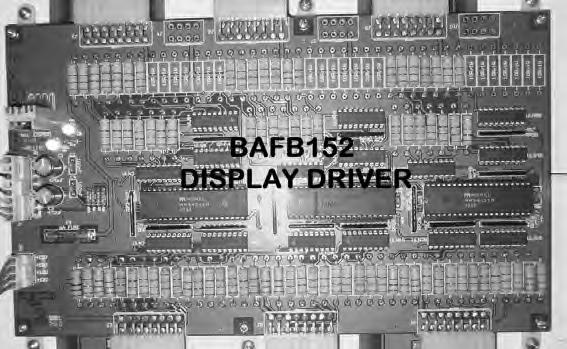
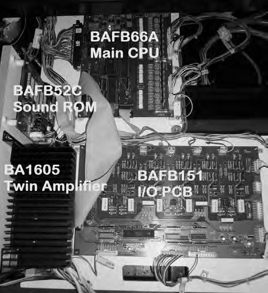
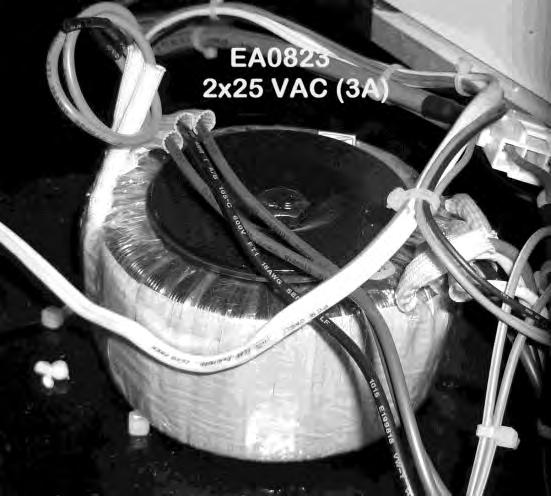
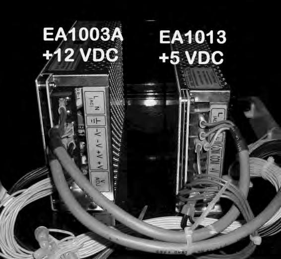
51 PARTS LOCATION DIAGRAM Continued Subwoofer and Transformer BAFB152 Display PCB Driver Main PCB, I/O PCB and Sound ROM PCB, Amplifier PCB Page 48


52 PARTS LOCATION DIAGRAM Continued Page 49
53 LAMPS * WARNING! * Always turn OFF Mains power and unplugged the game, before replacing any lamps. Always allow time for cooling as Lamps that have been active for a time may still be too hot to touch. COIN DOOR LAMPS The coin door lamps all are 12V/DC LED or equivalent and can be accessed through the coin door. BUTTON LAMPS The button lamps all are 12V/DC LED or equivalent and can be accessed inside the control panel PLATFORM LAMPS There are, 3 x 18 Watt (24 ) and 6 x 15 Watt (18 ) fluorescent tubes in base platform. Access is from the top and side of the platform. HEADER LAMPS These are 2 x 36 Watt (48 ) fluorescent tubes in the Header of the cabinet. Access is from the back of the header. * CAUTION! * Always replace the lamps with the same or equivalent size, wattage and voltage. Page 50
54 CLEANING AND CHECK UP MAINTENANCE EXTERIOR Regularly dust and clean the external cabinet areas as required, using a soft waterdamp cloth and mild soap. Check for blown bulbs and replace as required. Any scratches or marks in the glass or acrylic can be buffed out using car polish or cut and polish. * CAUTION! * Do not use solvents on the panels as it may affect the artwork. INTERIOR Regularly dust and vacuum the interior of the cabinet, taking care to remove any objects that may have fallen on the PCBs. Check and tighten all fixing hardware and fasteners as required. * WARNING! * Always turn OFF Mains power and unplugged the game, before cleaning the interior of the machine. Always after cleaning the cabinet interior, check all harness connectors and restore all loose or interrupted connections. Regularly check that all the Display and Button Lamps are operating through the Sounds, Lamps and Display Test. Replace any globes that are not operational. Page 51
55 BASE EXPLODED VIEW Fluorescent Page 52
56 SECTION B: TECHNICAL DETAILS It is advised that anybody using SECTION B for repairing or modifying any of the components of the game should be a qualified technician, having at least a basic knowledge of digital components, integrated circuits and electricity. B Page 53
57 LOCKING MECHANISM EXPLODED VIEW Motor for Locking Locking Mechanism Slider Locking Mechanism Base Lock/Unlock Switch Complete Locking Mechanism Assembly Page 54
58 POWER SUPPLY Operator's Manual Mega Stacker MAINS VOLTAGE ADJUSTMENT The Switch Mode Power Supply has a switch to set the mains voltage range. It is located at the rear of the game cabinet, and is accessed via the back door. Use a thin blade screwdriver to move the selector switch to the desired mains voltage (See Diagram Below) TRANSFORMER CONNECTORS Locate the machine transformer(s) from the back in the base of the cabinet. If unsure of the location of the transformer(s), refer to Parts location diagram page of this manual. Change the position of the ACTIVE or HOT WIRE input, (marked brown on the diagram), to the position for the desired mains voltage. (See Diagram Below) 6 WAY CONNECTOR PINOUT PIN FUNCTION 1 240VAC 2 220VAC 3 120VAC 4 110VAC 5 0VAV (NEUTRAL) 6 EARTH Page 55

.")
59 COIN OPTIONS REFERENCE GUIDE Installed on the coin door is a 9 way Molex connector. This connector can be used for connection to most electronic coin systems and electronic coin comparators. Please see below picture to understand the connection setup, The Coin harness supplied with the game, The Game is supplied standard with a harness to fit to NRI G13 and 2x Electronic Coin Comparator (LAI Games standard option). Other types of coin electronic harnessing can be supplied as requested, please contact your nearest LAI Games distributor. Page 56

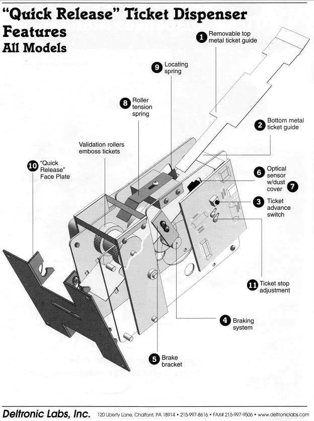
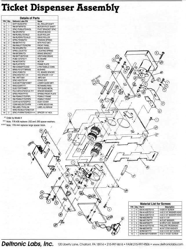
60 TICKET DISPENSER REFERENCE GUIDE Page 57
61 Page 58
62 Page 59
PLEASE NOTE: LAI GAMES V 1.3
 V 1.3 PLEASE NOTE: Read this manual BEFORE operating the machine. Keep this manual for your reference. Go to www.laigames.com click on Operator Access to register your games and receive of future updates.
PLEASE NOTE: LAI GAMES V 3.1
 V 3.1 PLEASE NOTE: Read this manual BEFORE operating the machine. Keep this manual for your reference. Go to www.laigames.com click on Operator Access to register your games and receive of future updates.
LAI GAMES 2004
 www.laigames.com 1st Ed. SKILL July 2004 READ THIS MANUAL BEFORE OPERATING THE MACHINE. KEEP THIS MANUAL FOR YOUR REFERENCE. LAI GAMES Correspondence regarding this machine should be addressed to your
LAI GAMES READ THIS MANUAL BEFORE OPERATING THE MACHINE. KEEP THIS MANUAL FOR YOUR REFERENCE.
 www.laigames.com READ THIS MANUAL BEFORE OPERATING THE MACHINE. KEEP THIS MANUAL FOR YOUR REFERENCE. LAI GAMES Correspondence regarding this machine should be addressed to your closest LAI GAMES office,
PLEASE NOTE: LAI Games
 PLEASE NOTE: Read this manual BEFORE operating the machine. Keep this manual for your reference. Go to www.laigames.com click on Operator Access to register your games and receive of future updates. LAI
LAI GAMES
 www.laigames.com READ THIS MANUAL BEFORE OPERATING THE MACHINE. KEEP THIS MANUAL FOR YOUR REFERENCE. LAI GAMES Correspondence regarding this machine should be addressed to your closest LAI GAMES office,
PLEASE NOTE: Preliminary. LAI Games
 Preliminary PLEASE NOTE: Read this manual BEFORE operating the machine. Keep this manual for your reference. Go to www.laigames.com click on Support to register your games and receive of future updates.
PLEASE NOTE: LAI GAMES V 3.0
 V 3.0 PLEASE NOTE: Read this manual BEFORE operating the machine. Keep this manual for your reference. Go to www.laigames.com click on Operator Access to register your games and receive of future updates.
PLEASE NOTE: LAI Games
 PLEASE NOTE: Read this manual BEFORE operating the machine. Keep this manual for your reference. Go to www.laigames.com click on Operator Access to register your games and receive of future updates. LAI
COASTAL AMUSEMENTS, INC, 1950 SWARTHMORE AVE LAKEWOOD, NJ (732)
") OPERATOR S MANUAL COASTAL AMUSEMENTS, INC, 1950 SWARTHMORE AVE LAKEWOOD, NJ 08701 (732) 905-6662 http://www.coastalamusements.com INTRODUCTION Subway Surfers is an amusement redemption game in which the
OPERATOR S MANUAL COASTAL AMUSEMENTS, INC, 1950 SWARTHMORE AVE LAKEWOOD, NJ 08701 (732) 905-6662 http://www.coastalamusements.com INTRODUCTION Subway Surfers is an amusement redemption game in which the
COASTAL AMUSEMENTS, INC, 1950 SWARTHMORE AVE LAKEWOOD, NJ (732)
") OPERATOR S MANUAL Version 1.1 COASTAL AMUSEMENTS, INC, 1950 SWARTHMORE AVE LAKEWOOD, NJ 08701 (732) 905-6662 http://www.coastalamusements.com INTRODUCTION Temple Run 2 is an amusement redemption game in
OPERATOR S MANUAL Version 1.1 COASTAL AMUSEMENTS, INC, 1950 SWARTHMORE AVE LAKEWOOD, NJ 08701 (732) 905-6662 http://www.coastalamusements.com INTRODUCTION Temple Run 2 is an amusement redemption game in
Operators Manual (Manual A)
") CD201 SINGLE COLUMN CARD DISPENSER Operators Manual (Manual A) Contents A1 Scope... 1 A2 Specifications... 1 A3 Installation... 2 3.1 Unpacking and inspection... 2 3.2 Opening and closing the door... 2
CD201 SINGLE COLUMN CARD DISPENSER Operators Manual (Manual A) Contents A1 Scope... 1 A2 Specifications... 1 A3 Installation... 2 3.1 Unpacking and inspection... 2 3.2 Opening and closing the door... 2
PLEASE READ ALL INSTRUCTIONS BEFORE OPERATING THIS MACHINE
 PLEASE READ ALL INSTRUCTIONS BEFORE OPERATING THIS MACHINE TRIGGER HAPPY IS AN EXCITING NEW SHOOTING GALLERY GUN GAME FROM FUN INDUSTRIES. THIS MACHINE IS DESIGNED TO DISPENSE 2 PRIZES AS WELL AS TICKET
To Purchase This Game, Visit BMI Gaming Or Contact International Sales at (USA) The Simpsons Soccer
 The Simpsons Soccer") The Simpsons Soccer STANDARD OPERATING MANUAL Rev. 9-4-12 (Software Version: 07-30-12) Coastal Amusements, Inc. 1950 Swarthmore Ave. Lakewood, NJ 08701 +1 (732) 905-6662 sales@coastalamusements.com http://www.coastalamusements.com
The Simpsons Soccer STANDARD OPERATING MANUAL Rev. 9-4-12 (Software Version: 07-30-12) Coastal Amusements, Inc. 1950 Swarthmore Ave. Lakewood, NJ 08701 +1 (732) 905-6662 sales@coastalamusements.com http://www.coastalamusements.com
BO-01 Blackout. Operation & Service Manual. Version 1.1. * Read this manual before use
 BO-01 Blackout Operation & Service Manual Version 1.1 * Read this manual before use General Remark If you encounter any difficulties or if you need support on how to update and/ or install your Blackout
ABOUT SMOKIN' TOKEN EXTREME
 ABOUT SMOKIN' TOKEN EXTREME Operators distinguish Smokin Token as one of the great redemption success stories, and are now able to share in that unprecedented success for yet another generation. Smokin
FD 125 Large-Format Card Cutter
 FD 125 Large-Format Card Cutter 3/201 OPERATOR MANUAL Page 2 Table of Contents SAFETY PRECAUTIONS... 4 Introduction... 5 Specifications... 5 Accessories... 5 Major Components and Assemblies... 6 Control
OPERATOR S MANUAL COASTAL AMUSEMENTS, INC, 1950 SWARTHMORE AVE LAKEWOOD, NJ (732)
") a mobile app to coin-op game OPERATOR S MANUAL COASTAL AMUSEMENTS, INC, 1950 SWARTHMORE AVE LAKEWOOD, NJ 08701 (732) 905-6662 http://www.coastalamusements.com INTRODUCTION Rail Rush is an amusement redemption
a mobile app to coin-op game OPERATOR S MANUAL COASTAL AMUSEMENTS, INC, 1950 SWARTHMORE AVE LAKEWOOD, NJ 08701 (732) 905-6662 http://www.coastalamusements.com INTRODUCTION Rail Rush is an amusement redemption
Operator Menus Guide Incredible Technologies, Inc. All Rights Reserved
 Operator Menus Guide 2014 Incredible Technologies, Inc. All Rights Reserved Operator Menus Guide OPERATOR MENUS NAVIGATING THE MENU SYSTEM The Operator Menus allow you to adjust the machine for your specific
CHUCK E. CHEESE S MATCH GAME
 CHUCK E. CHEESE S MATCH GAME PLAYING THE GAME Chuck E. Cheese s Match Game is a memory match game for one player. The player is shown nine curtains which reveal five different characters: Chuck E. Cheese,
UPLIFT 2-Leg Height Adjustable Standing Desk
 UPLIFT -Leg Height Adjustable Standing Desk Also watch our assembly video http://bit.ly/9ywwh DIRECTIONS FOR ASSEMBLY AND USE TABLE OF CONTENTS PAGE Safety and Warnings Usage Parts List Assembly Instructions
TABLE OF CONTENTS. PDF 文件使用 "pdffactory Pro" 试用版本创建
 TABLE OF CTENTS Version: 4.3-003 Time: 2008-3-5 SAFTTY INSTRUCTIS...1 INTRODUCTI...2 PACKAGING...2 ACCERSSORIES...2 TECHNICAL PARAMETERS...2 LOCATI REQUIREMENTS...2 PLAYING INSTRUCTIS...3 ADJUSTING THE
Service Manual Innovative Concepts in Entertainment
 Service Manual Innovative Concepts in Entertainment 10123 Main Street Clarence, New York 14031 (716) 759-0360 www.icegame.com Table of Contents What s included 3 Safety and Warnings 4 Game Assembly 5-9
.VEGAS NIGHT. The following developer is responsible for the declaration: (Manual Version: VEG_INT _7B) VEG_INT _7B 1
 VEG_INT _7B 1") .VEGAS NIGHT. The following developer is responsible for the declaration: Astro Corp. 10F, No.111-1, HSING DE RD, SANCHUNG CITY, TAIPEI COUNTY, TAIWAN Telephone:+886-2-8511-0555 Facsimile:+886-2-8511-0556
.VEGAS NIGHT. The following developer is responsible for the declaration: Astro Corp. 10F, No.111-1, HSING DE RD, SANCHUNG CITY, TAIPEI COUNTY, TAIWAN Telephone:+886-2-8511-0555 Facsimile:+886-2-8511-0556
Shelti, Inc. 333 Morton Street Bay City, MI Phone Fax. Bayside Dollar Bill Acceptor Pool Table Manual & Instructions
 Shelti, Inc. 333 Morton Street Bay City, MI 48706 989-893-1739 Phone 989-893-1809 Fax Bayside Dollar Bill Acceptor Pool Table Manual & Instructions Contents Section-1 Introduction Bayside DBA Pool Table
(SUBSINO CASINO GAME HIGH RESOLUTION SERIES)
") ALADDIN (SUBSINO CASINO GAME HIGH RESOLUTION SERIES) Discover the excitement of fast-hitting video slot plus two progressive jackpots. Players will be flying with the gliding carpet of Aladdin! Players
ALADDIN (SUBSINO CASINO GAME HIGH RESOLUTION SERIES) Discover the excitement of fast-hitting video slot plus two progressive jackpots. Players will be flying with the gliding carpet of Aladdin! Players
UPLIFT 3-Leg Desk Instructions for. Solid Wood Desktops. pictured: 3-leg desk; solid-wood top, with right hand return TABLE OF CONTENTS
 UPLIFT 3-Leg Desk Instructions for Solid Wood Desktops pictured: 3-leg desk; solid-wood top, with right hand return TABLE OF CONTENTS PAGE 1 Safety and Warnings 2 2 Usage 2 3 Parts List 3 4 Assembly Instructions
TABLE OF CONTENTS 1 BRIEF INSTRUCTION NOTICE... 1
 TABLE OF CONTENTS Ver:1.01 Time:2010-12-16 1 BRIEF INSTRUCTION... 1 2 NOTICE... 1 2-1. SAFTTY INSTRUCTIONS...1 2-2. NOTICE FOR OPERATION...1 3 ACCESSORIES... 1 4 HOW TO PLAY... 2 5 TECHNICAL PARAMETERS...
С 800 CASSIDA C 800 HIGH SPEED COIN COUNTER
 С 800 CASSIDA C 800 HIGH SPEED COIN COUNTER This manual contains important information on safety measures and operational features. Please read it carefully before operating your coin counter, and keep
INSTALLATION MANUAL PBL-UMP
 INSTALLATION MANUAL PBL-UMP Table of Contents Warning Statements... 4 Parts List... 5 Installation Tools... 5 Features... 7 Projector Preparation... 8 Bracket Installation... 10 Leveling the Mounting Bracket...
OWNERS AND SERVICE MANUAL 2001 INNOVATIVE CONCEPTS IN ENTERTAINMENT INC.
 OWNERS AND SERVICE MANUAL 2001 INNOVATIVE CONCEPTS IN ENTERTAINMENT INC. 10123 MAIN STREET, CLARENCE, NEW YORK 14031 SERVICE 716-759-0360 SALES 716-759-0370 FAX 716-759-0390 E MAIL play@icegame.com TABLE
UPLIFT 2-Leg Height Adjustable Standing Desk - For use with UPLIFT Eco and Eco Curve desktops -
 UPLIFT -Leg Height Adjustable Standing Desk - For use with UPLIFT Eco and Eco Curve desktops - DIRECTIONS FOR ASSEMBLY AND USE TABLE OF CONTENTS Please Note PAGE Safety and Warnings Usage Parts List Assembly
ATTENTION! There is only ONE set of keys per machine. Locks and keys CANNOT be replaced. PLEASE keep your keys in a safe place.
 Instruction Manual ATTENTION! This manual is for reference only. Each machine will be a little different depending upon model and manufacturer. All slot machines essentially program and play the same.
CONNECTOR (10PIN) BLACK BEARD PARTS SIDE
 BLACK BEARD PARTS SIDE") CONNECTOR (10PIN) PARTS SIDE SOLDER SIDE GND 1 GND GND 2 GND (*1) +5V 3 +5V +5V 4 +5V (*1) +12V 5 +12V +12V 6 +12V Ticket Dispenser Enable 7 (*2) Hopper SSR 8 GND 9 GND GND 10 GND (1) DC +5V 2A and DC
CONNECTOR (10PIN) PARTS SIDE SOLDER SIDE GND 1 GND GND 2 GND (*1) +5V 3 +5V +5V 4 +5V (*1) +12V 5 +12V +12V 6 +12V Ticket Dispenser Enable 7 (*2) Hopper SSR 8 GND 9 GND GND 10 GND (1) DC +5V 2A and DC
USER MANUAL ENGLISH 1450 COIN COUNTER & SORTER
 USER MANUAL ENGLISH 1450 COIN COUNTER & SORTER INTRODUCTION ENGLISH Thank you for purchasing the Safescan 1450 coin counter and sorter. For proper use and maintenance, we advise to read this user manual
PIGS MIGHT FLY USER MANUAL
 PIGS MIGHT FLY USER MANUAL This manual is suitable for use in countries below: USA The UK ASIA - 1 - [Table of Contents] Simple Facts About The Machine 3 Introduction... 4 Simple Maintenance & Servicing
UPLIFT Height Adjustable Standing Desk 3-Leg (T-Frame) DIRECTIONS FOR ASSEMBLY AND USE
 DIRECTIONS FOR ASSEMBLY AND USE") UPLIFT Height Adjustable Standing Desk 3-Leg (T-Frame) DIRECTIONS FOR ASSEMBLY AND USE CAUTION MAKE SURE NO OBSTACLES ARE IN THE DESK S PATH AND ALL CORDS ARE OF APPROPRIATE LENGTH FOR DESK TRAVEL. FAILURE
UPLIFT Height Adjustable Standing Desk 3-Leg (T-Frame) DIRECTIONS FOR ASSEMBLY AND USE CAUTION MAKE SURE NO OBSTACLES ARE IN THE DESK S PATH AND ALL CORDS ARE OF APPROPRIATE LENGTH FOR DESK TRAVEL. FAILURE
STANDARD OPERATING MANUAL Rev
 STANDARD OPERATING MANUAL Rev. 5-31-12 (Software Version: 05-31-12) Coastal Amusements, Inc. 1950 Swarthmore Ave. Lakewood, NJ 08701 +1 (732) 905-6662 sales@coastalamusements.com http://www.coastalamusements.com
Pac-Man Ball 10p. Installation Supplement Read this supplement before installation
 Pac-Man Ball 10p Installation Supplement Read this supplement before installation The major attraction of this game is the provision of high volumes of coins flowing in and out so it is crucial to adjust
~ Pizzeria ~ The following developer is responsible for the declaration: Astro Corp.
 ~ Pizzeria ~ The following developer is responsible for the declaration: Astro Corp. 10F, No. 111-1 HSING DE RD, SANCHUNG CITY, TAIPEI COUNTY, TAIWAN Tel:+886-2-8511-0555 Fax:+886-2-8511-0556 E-mail:sales@astrocorp.com.tw
Standard PS-P61 Punch Stapler
 Standard PS-P61 Punch Stapler Instruction Manual Provided By http://www.mybinding.com http://www.mybindingblog.com PUNCH STAPLE PS-P61 Important Information - This manual is designed to help you to install,
Step- by- Step Assembly Instructions (with photos)
") Step- by- Step Assembly Instructions (with photos) Page Unpack the Photo Booth... 2 Secure the Power Cord... 3 Install the Camera Topper... 4 Load Paper into the Printers... 8 Load the Ink Film and Ink
Step- by- Step Assembly Instructions (with photos) Page Unpack the Photo Booth... 2 Secure the Power Cord... 3 Install the Camera Topper... 4 Load Paper into the Printers... 8 Load the Ink Film and Ink
Jarvis standing desk. Assembly instructions. For assembly assistance, visit fully.com/howtojarvis or call or
 Jarvis standing desk Assembly instructions For assembly assistance, visit fully.com/howtojarvis or call 888-508-3725 or email support@fully.com Thank you for choosing a Jarvis desk from Fully. Cautions
Boink Kiosk System Administration Manual
 Boink Kiosk System Administration Manual Last updated on May 21st, 2002 Table of Contents INTRODUCTION Boink Kiosk System...2 Safety Precautions...3 KIOSK SYSTEM NORMAL OPERATION SF6 Kiosk General Description
PIRATES ISLAND (SUBSINO CASINO GAME XVGA SERIES)
") PIRATES ISLAND (SUBSINO CASINO GAME XVGA SERIES) This game takes a theme you already love Pirates Island - to the next level with new XVGA 5-reels and 9-lines of excitement. State-of-the-art graphics promote
PIRATES ISLAND (SUBSINO CASINO GAME XVGA SERIES) This game takes a theme you already love Pirates Island - to the next level with new XVGA 5-reels and 9-lines of excitement. State-of-the-art graphics promote
EmagiKit. Privacy Pod Plus. Quiet. Easy. Affordable. INSTRUCTIONS ASSEMBLY
 EmagiKit Privacy Pod Plus Quiet. Easy. Affordable. INSTRUCTIONS ASSEMBLY DIMENSIONS AND COMPONENTS 47 47 Ceiling Unit 2-B 2-L 2-R Glass Door Corner Trim Door Handle 90 Adjustable Height Work Surface 1-B
APES HD-7700 Version Operator s Training Manual
 APES-14-77 HD-7700 Version Operator s Training Manual Issue A1 09/03 P/N 900599 Performance Design Inc. 2350 East Braniff St. Boise Idaho 83716 This manual contains very important safety information and
ACD3180 Card Dispenser/Encoder System. User Manual and Setup Guide. Choose ACDI for all your document vending needs
 ACD3180 Card Dispenser/Encoder System User Manual and Setup Guide Choose ACDI for all your document vending needs INTRODUCTION... 1 OVERVIEW... 1 SETUP... 2 UNPACKING THE DISPENSER SYSTEM... 2 PHYSICAL
A VIDEO REDEMPTION/AMUSEMENT GAME (Revision: )
") A VIDEO REDEMPTION/AMUSEMENT GAME (Revision: 12-09-08) COASTAL AMUSEMENTS, INC. 1935 SWARTHMORE AVE LAKEWOOD, NJ 08701 (USA) TEL: 01-732-905-6662 FAX: 01-732-905-6815 E-MAIL: sales@coastalamusements.com
A VIDEO REDEMPTION/AMUSEMENT GAME (Revision: 12-09-08) COASTAL AMUSEMENTS, INC. 1935 SWARTHMORE AVE LAKEWOOD, NJ 08701 (USA) TEL: 01-732-905-6662 FAX: 01-732-905-6815 E-MAIL: sales@coastalamusements.com
INSTALLATION MANUAL PBC-UMS
 INSTALLATION MANUAL. PBC-UMS Premier Mounts 3130 E. Miraloma Avenue Anaheim, CA 92806 Phone: (800) 368-9700 Fax: (800) 832-4888 mounts@mounts.com www.mounts.com Rev. 01 PBL-110 Projector Mount Page 2 Installation
SHIRTS AND SKINS JUNIOR EDITION COASTAL AMUSEMENTS INC SWARTHMORE AVE LAKEWOOD, NJ TEL: FAX:
 SHIRTS AND SKINS JUNIOR EDITION COASTAL AMUSEMENTS INC. 1935 SWARTHMORE AVE LAKEWOOD, NJ 08701 TEL: 732-905-6662 FAX: 732-905-6815 W632 SHIRTS AND SKINS FUSE AT MAIN BOARDS F1, 20 mm 2A GATE MOTOR; F2,
TIGER HOOK 2004 AMCOE INC.
 TIGER HOOK 2004 AMCOE INC. PIN PARTS SIDE SOLDER SIDE PIN 1 VIDEO RED VIDEO GREEN 1 2 VIDEO BLUE VIDEO SYNC 2 3 SPEAKER + SPEAKER - 3 4 EXTRA - 4 5 EXTRA - STOP 2 EXTRA - ALL STOP 5 6 EXTRA - STOP 3 6
GOLDEN CITY (5 REELS 25 LINES VIDEO XVGA SLOT GAME)
") GOLDEN CITY (5 REELS 25 LINES VIDEO XVGA SLOT GAME) Golden City designs with the object of operating professional and amused game of casino, rather than making classic slot game. It s really extraordinary
GOLDEN CITY (5 REELS 25 LINES VIDEO XVGA SLOT GAME) Golden City designs with the object of operating professional and amused game of casino, rather than making classic slot game. It s really extraordinary
TR3301 Tissue Vending Machine User Manual Panda Vending Limited
 TR3301 Tissue Vending Machine User Manual Panda Vending Limited www.pandavending.com Preface Welcome to use our vending machine! Before you install and operate this machine, please read the manual carefully.
Separating Sides 5. Payout and Adjustments 5. Wheel location and ball scoring 7. Ball Lift Operation 7. Ball Drop Operation 7
 Table of Contents Manual Revision History 3 Basic Components 4 Game Setup 4 Separating Sides 5 Payout and Adjustments 5 Game Play Sequence/Behavior 6 Technical Operation 7 Wheel location and ball scoring
Weatheradio Alert ( ) Features Faxback Doc. # 47648
 Features Faxback Doc. # 47648") (120-0140) Features Faxback Doc. # 47648 Your REALISTIC WEATHERADIO ALERT is specially designed to receive weather reports broadcast 24 hours a day by the National Weather Service. Special stations provide
(120-0140) Features Faxback Doc. # 47648 Your REALISTIC WEATHERADIO ALERT is specially designed to receive weather reports broadcast 24 hours a day by the National Weather Service. Special stations provide
A VIDEO REDEMPTION/AMUSEMENT GAME (Revision: )
") A VIDEO REDEMPTION/AMUSEMENT GAME (Revision: 02-15-08) COASTAL AMUSEMENTS, INC. 1935 SWARTHMORE AVE LAKEWOOD, NJ 08701 (USA) TEL: 01-732-905-6662 FAX: 01-732-905-6815 E-MAIL: sales@coastalamusments.com
A VIDEO REDEMPTION/AMUSEMENT GAME (Revision: 02-15-08) COASTAL AMUSEMENTS, INC. 1935 SWARTHMORE AVE LAKEWOOD, NJ 08701 (USA) TEL: 01-732-905-6662 FAX: 01-732-905-6815 E-MAIL: sales@coastalamusments.com
FOLDING MACHINE PF-45A OPERATOR MANUAL 1. FUNCTION
 FOLDING MACHINE OPERATOR MANUAL 1. FUNCTION The folding machine is used to fold documents stand alone or in combination with a system 7. Sheets can be folded in various types. These are: single fold; letter
The Circus. Manual Version: TC_US TC_US
 The Circus Manual Version: 2 Table of Contents Interface Interface & Button Layout p. 04 Setup Menu p. 05 Setup Password p. 06 Information p. 07 Data Setting p. 08 Confirm Reset p. 10 Bookkeeping p. 11
Super Shot Deluxe Assembly and Operating Manual
 SPECIFICATIONS... 3 INTRODUCTION... 4 WARNINGS... 4 ASSEMBLY INSTRUCTIONS... 5 MAJOR GAME COMPONENT DEFINITIONS... 5 PRE-ASSEMBLY... 7 ASSEMBLY... 9 TESTING... 11 COIN TEST:... 11 TICKET TEST:... 12 SENSOR
FRUIT BONUS 2 nd Generation 2004 AMCOE INC.
 PIN PARTS SIDE SOLDER SIDE PIN 1 VIDEO RED VIDEO GREEN 1 2 VIDEO BLUE VIDEO SYNC 2 3 SPEAKER + SPEAKER - 3 4 EXTRA - 4 5 EXTRA - STOP 2 EXTRA - ALL STOP 5 6 EXTRA - STOP 3 6 7 TICKET OUT BUTTON - panel
Linear Hook- on Worksurfaces
 Linear Hook- on Worksurfaces Linear Hook-On Worksurfaces come in three depths and seven lengths. Different worksurfaces have different reqirements for installation that are outlined below. 27 inch deep
FLEXRISE2 VERSION. 2 LEG / 2 MOTOR ELECTRIC TABLE BASE (36 to 72 ) **PATENT PENDING**
 **PATENT PENDING**") FLEXRISE2 2 LEG / 2 MOTOR ELECTRIC TABLE BASE (36 to 72 ) VERSION A INSTRUCTION MANUAL CONTENTS: FLEX-MU-2L3S-C3672-K4# FEET-ADJ-UNV-2430# **PATENT PENDING** MAX Load 265 lbs (120 KG) Equally Divided MAX
FLEXRISE2 2 LEG / 2 MOTOR ELECTRIC TABLE BASE (36 to 72 ) VERSION A INSTRUCTION MANUAL CONTENTS: FLEX-MU-2L3S-C3672-K4# FEET-ADJ-UNV-2430# **PATENT PENDING** MAX Load 265 lbs (120 KG) Equally Divided MAX
AN AMUSEMENT/REDEMPTION VIDEO GAME (Revision: ) STANDARD VERSION
 STANDARD VERSION") AN AMUSEMENT/REDEMPTION VIDEO GAME (Revision: 09-10-12) STANDARD VERSION COASTAL AMUSEMENTS, INC. 1950 SWARTHMORE AVE LAKEWOOD, NJ 08701 (USA) TEL: 01-732-905-6662 FAX: 01-732-905-6815 E-MAIL: sales@coastalamusements.com
AN AMUSEMENT/REDEMPTION VIDEO GAME (Revision: 09-10-12) STANDARD VERSION COASTAL AMUSEMENTS, INC. 1950 SWARTHMORE AVE LAKEWOOD, NJ 08701 (USA) TEL: 01-732-905-6662 FAX: 01-732-905-6815 E-MAIL: sales@coastalamusements.com
MBM Sprint 3000 Booklet Maker
 MBM Sprint 3000 Booklet Maker Instruction Manual Provided By http://www.mybinding.com http://www.mybindingblog.com SPRINT 3000 BOOKLETMAKER OPERATION MANUAL IMP oper3500.doc Page 1 23/01/2004 CONTENTS
OPERATING MANUAL. Rev
 OPERATING MANUAL Rev. 05-17-10 (Software Version: OPER515) Coastal Amusements, Inc. 1935 Swarthmore Ave. Lakewood, NJ 08701 (732) 905-6662 http://www.coastalamusements.com INTRODUCTION The coin-operated
Operating Guide. HT25 Multi Side Tabber & Stamp Affixer. HASLER America s better choice. Mailing Systems And Solutions
 Operating Guide Mailing Systems And Solutions HASLER America s better choice HT25 Multi Side Tabber & Stamp Affixer An ISO 9001 Quality System Certified company Rev. 8/25/2010 Please record the following
MBM 307A / 407A PF Automatic Folders
 MBM 307A / 407A PF Automatic Folders Instruction Manual Provided By http://www.mybinding.com http://www.mybindingblog.com OPERATION MANUAL MBM 307A / 407A AUTOMATIC FOLDERS 1-800-223-2508 www.mbmcorp.com
FLT-02 User Manual. Contents. Page 2 Page 3 Page 4 Page 5-7 Page 8
 FLT-0 User Manual Contents Caution/Liability Technical Specifications Parts Assembly Instructions Operational/Reset Procedure, Troubleshooting Dimensions Page Page 3 Page 4 Page 5-7 Page 8 Page 9 Caution
AutoSeal FD 2002/FD 2032 FE 2002/FE 2032 OPERATOR MANUAL FIRST EDITION
 AutoSeal FD 2002/FD 2032 FE 2002/FE 2032 10/2012 OPERATOR MANUAL FIRST EDITION TABLE OF CONTENTS SUBJECT PAGE DESCRIPTION 1 SPECIFICATIONS 1 UNPACKING 2 2000/2032 Components 2 Optional Conveyor Components
7-4-2 (4) Set up mode (Play fee, BGM, Tilt sensor)
 Set up mode (Play fee, BGM, Tilt sensor)") 7-4-2 (4) Set up mode (Play fee, BGM, Tilt sensor) A B Maintenance door Display A shows which mode you are in. Display B shows which content you are selecting. 1 Open the maintenance door that is locked
7-4-2 (4) Set up mode (Play fee, BGM, Tilt sensor) A B Maintenance door Display A shows which mode you are in. Display B shows which content you are selecting. 1 Open the maintenance door that is locked
ETX Powered Loudspeaker Accessories
 ETX Powered Loudspeaker Accessories ETX-BRKT10, ETX-BRKT12, ETX-BRKT15, ETX-TCA-S, ETX-TCA-L, and ETX-BRKT35 en Installation Guide en 3 Table of contents 1 Safety 4 2 Installation 6 2.1 Wall mount bracket
INSTALLATION MANUAL ELPMBUNI
 INSTALLATION MANUAL ELPMBUNI Warning Statements WARNING: WARNING: WARNING: WARNING: PREMIER MOUNTS DOES NOT WARRANT AGAINST DAMAGE CAUSED BY THE USE OF ANY PREMIER MOUNTS PRODUCT FOR PURPOSES OTHER THAN
Series 7 - Adjustable Height Tables
 Page 1 of 22 Series 7 - Adjustable Height Tables Installation Instructions Tools required: #2 Phillips Bit with Extension #2 Square Drive Bit 4mm Hex Drive Bit Series 7 - Adjustable Height Tables Installation
AutoSeal FD 2006IL / FE 2006IL
 AutoSeal FD 2006IL / FE 2006IL FI / FJ Series 06/2018 OPERATOR MANUAL First Edition TABLE OF CONTENTS DESCRIPTION 1 SPECIFICATIONS 1 UNPACKING 1 SETUP 2 Sealer Alignment Base Setup 2 Sealer Setup 2-4
AutoSeal FD 1506 Plus / FE 1506 Plus
 AutoSeal FD 1506 Plus / FE 1506 Plus FK / FL SERIES 06/2018 OPERATOR MANUAL FIRST EDITION TABLE OF CONTENTS DESCRIPTION 1 UNPACKING AND SET-UP 2 CONTROL PANEL 3 OPERATION 3 FOLD PLATE ADJUSTMENT 4 SETTING
JEEP JK ( 3 DOOR ) SLIMLINE II - FULL TRAY EXTREME RACK KIT
 SLIMLINE II - FULL TRAY EXTREME RACK KIT") JEEP JK ( 3 DOOR ) SLIMLINE II - FULL TRAY EXTREME RACK KIT FAJK004 / KRJW016T INSTALL TIME: 2 Hours NOTE: Your Jeep JK (3 Door) Extreme Roof Rack Kit consists of four boxes. (1) the Tray, (2) the Roll
JEEP JK ( 3 DOOR ) SLIMLINE II - FULL TRAY EXTREME RACK KIT FAJK004 / KRJW016T INSTALL TIME: 2 Hours NOTE: Your Jeep JK (3 Door) Extreme Roof Rack Kit consists of four boxes. (1) the Tray, (2) the Roll
Cabinet Storage Products
 Assembly Instructions Storage Products (UltraStor, Acoustis, Adjustable Shelf, Cover Panels, Closure Panels) Wood Compartment Doors Full Wood Door Compartment Grille Doors Full Grille Door No Doors Contents
Riverside. Windward Bay EntertaInment Wall System Assembly Instructions. Made In Viet Nam. Right Pier. Bridge & Back Panel.
 EntertaInment Wall System Page 1 of 12 Product No. 42840 42848 42849 42843 Product Description Console Left Pier Right Pier Bridge & Back Panel Right Pier Bridge & Back Panel Left Pier 63" Inch Ent. Console
JEEP JK ( 3 DOOR ) SLIMLINE II - FULL TRAY EXTREME RACK KIT
 SLIMLINE II - FULL TRAY EXTREME RACK KIT") JEEP JK ( 3 DOOR ) SLIMLINE II - FULL TRAY EXTREME RACK KIT FAJK005 / KRJW016T INSTALL TIME: 5 Hours NOTE: Your Jeep JK (3 Door) Extreme Roof Rack Kit consists of four boxes. (1) the Tray, (2) the Roll
JEEP JK ( 3 DOOR ) SLIMLINE II - FULL TRAY EXTREME RACK KIT FAJK005 / KRJW016T INSTALL TIME: 5 Hours NOTE: Your Jeep JK (3 Door) Extreme Roof Rack Kit consists of four boxes. (1) the Tray, (2) the Roll
OPERATIONS MANUAL. Port-O-Slitter
 Tapco Products Company The World Leader in Specialty Tools for the Professional Port-O-Slitter OPERATIONS MANUAL General instructions, set up, accessories and guide to using your portable precision slitting,
Series 7 AdjusTable Height Tables
 Series 7 AdjusTable Height Tables Tools required: #2 Phillips Bit with Extension #2 Square Drive Bit 4mm Hex Drive Bit #3 Phillips Bit If you have a problem, question, or request, call your local dealer,
1200 DPS Programmable Digital Powder System
 1200 DPS Programmable Digital Powder System WARNINGS AND CAUTIONS: If the 1200 DPS does not read zero on the display, DO NOT DISPENSE POWDER. The scale must be zeroed before use. If powder is dispensed
JEEP JK ( 5 DOOR ) SLIMLINE II - FULL TRAY EXTREME RACK KIT
 SLIMLINE II - FULL TRAY EXTREME RACK KIT") JEEP JK ( 5 DOOR ) SLIMLINE II - FULL TRAY EXTREME RACK KIT FAJK001 / KRJW014T INSTALL TIME: 2.5 Hours NOTE: Your Jeep JK (5 Door) Extreme Roof Rack Kit consists of four boxes. (1) the Tray, (2) the Roll
JEEP JK ( 5 DOOR ) SLIMLINE II - FULL TRAY EXTREME RACK KIT FAJK001 / KRJW014T INSTALL TIME: 2.5 Hours NOTE: Your Jeep JK (5 Door) Extreme Roof Rack Kit consists of four boxes. (1) the Tray, (2) the Roll
FREUD. Operating Instructions. JS104K Biscuit Joiner Kit
 FREUD Operating Instructions JS104K Biscuit Joiner Kit Contents Safety General Safety Rules Additional Safety Rules for Biscuit Joiners Functional Description and Specifications Symbols Parts and Feature
Multi Drop Bus 5-Tube Coin Changer. Series. Service Manual B D A C E SAT
 Multi Drop Bus 5-Tube Coin Changer Series Service Manual DIS C/C A C E MOD B D SAT AUT 2 TABLE OF CONTENTS Page 1 Outline... 3 2 Product Model Names... 4 3 General Specifications... 5 4 Detailed Specifications...
JEEP JK ( 5 DOOR ) SLIMLINE II - FULL TRAY EXTREME RACK KIT
 SLIMLINE II - FULL TRAY EXTREME RACK KIT") JEEP JK ( 5 DOOR ) SLIMLINE II - FULL TRAY EXTREME RACK KIT FAJK002 / KRJW014T INSTALL TIME: 5 Hours NOTE: Your Jeep JK (5 Door) Extreme Roof Rack Kit consists of four boxes. (1) the Tray, (2) the Roll
JEEP JK ( 5 DOOR ) SLIMLINE II - FULL TRAY EXTREME RACK KIT FAJK002 / KRJW014T INSTALL TIME: 5 Hours NOTE: Your Jeep JK (5 Door) Extreme Roof Rack Kit consists of four boxes. (1) the Tray, (2) the Roll
BENCHMARK GAMES, INC. IS THE EXCLUSIVE NORTH AMERICAN MANUFACTURER AND DISTRIBUTOR OF POKERKARD. PokerKard USA REV 1.0. Page 1
 COPYRIGHT 2008 NOVA PRODUCTIONS LTD. ALL RIGHTS RESERVED. PATENT PEN BENCHMARK GAMES, INC. IS THE EXCLUSIVE NORTH AMERICAN MANUFACTURER AND DISTRIBUTOR OF POKERKARD. INNOVATION, SPECIFICALLY DESIGNED FOR
US-0320 Reel Slot Operator Menu
 US-0320 Reel Slot Operator Menu Pocket Reference Provided by Aristocrat Field Services To access Main menu, turn attendant keyswitch counterclockwise. Menu items shown in brackets [ ] are displayed on
OPERATION MANUAL MBM 207M MANUAL FOLDER
 OPERATION MANUAL MBM 207M MANUAL FOLDER 1-800-223-2508 www.mbmcorp.com 1 Safety Instructions Definition of Symbols and Notes The following names and signs stand for possible dangers: Danger This symbol
Assembly Instructions
 InTandem Table System November 20 InTandem Table System - Worksurface #4 x/" 4 wood screw power beam Tools Provided T-0 Extended Torx Driver T-25 Torx Driver Additional Tools Required Soft protective
Removing and Replacing the Y-truck
 Service Documentation Removing and Replacing the Y-truck To remove and replace the Y-truck you will need the following tools: 4mm Allen wrench 12mm stamped flat wrench #2 Phillips screwdriver (magnetic
CashConcepts CCE 4000
 CashConcepts CCE 4000 Coin Counter and Sorting Machine User Manual Introduction Thank you for choosing the CCE 4000. This coin counting and coin sorting machine is designed to simplify the daily cash or
FS-527 Finisher INSTALLATION MANUAL
 FS-527 Finisher INSTALLATION MANUAL Index FS-527 (d-color MF360/MF280/MF220) I. Accessory parts... II. Confirmation before installation... 2 III. Installation procedures... 3 FS-527 (d-color MF45) I. Accessory
S5-ADU. Front... 4 Rear... 4
 Trantec ANTENNA DISTRIBUTOR INSTRUCTION MANUAL S5-ADU Thank you for purchasing TRANTEC Antenna Distributor. Please carefully follow the instructions in this manual to ensure long, trouble-free use of your
Allegro Home Office Assembly Instructions. Tipping Restraint. Bun Foot W/ Leveler. 4 pcs.
 email: info@riverside-furniture.com Allegro Home Office Assembly Instructions Components and Hardware List Page 1 of 5 Made in China Shelf Pin Wood Shelf File Rod & Clips 1/2"Wood Screw A 16 pcs. B 4 pcs.
Elements Pole Mounting System
 Elements Pole Mounting System Installation Manual www.peavey.com Elements Pole Mounting System Installation Manual The Elements Pole Mounting System is a simple and straightforward pole mounting solution
Before Assembling the Storage Wall
 Chapter 1 Assembling the Lista Storage Wall Lista provides two types of standard Storage Walls: B251 and B255. The design, construction, assembly, and quality are identical for both types, however, B251
FD 1500 AutoSeal 12/07 OPERATOR MANUAL THIRD EDITION
 FD 1500 AutoSeal 12/07 OPERATOR MANUAL THIRD EDITION TABLE OF CONTENTS FD 1500 shown with optional cabinet TOPIC PAGE DESCRIPTION, UNPACKING, SET-UP, CONTROLS 1 OPERATION 2 FOLD PLATE INSTALLATION, ADJUSTMENT
Operator Manual. Booklet Maker BM 60. Doc No. T10171
 Booklet Maker BM 60 Operator Manual Doc No. T10171 Morgana Systems Limited United Kingdom www.morgana.co.uk Telephone: ( 01908 ) 608888 Facsimile: ( 01908 ) 692399 Part no: 60249 Doc no: T10171 Rev. date: