PLEASE NOTE: LAI Games
|
|
|
- Lindsey Morris
- 5 years ago
- Views:
Transcription


1 PLEASE NOTE: Read this manual BEFORE operating the machine. Keep this manual for your reference. Go to click on Operator Access to register your games and receive of future updates. LAI Games

2 LAI Games Correspondence regarding this machine should be addressed to your closest LAI Games office, or LAI Games Distributor. For contact details, refer to the back page of this manual. Copyright Notice: LAI Games Authorization is hereby provided to you to copy this manual in its entirety provided such copies are used for non-commercial purposes and solely for use with LAI Games products. This authorization is specifically conditioned to include all legends, copyright, proprietary and other notices which appear herein are unaltered on any and all copies you make. LAI Games
3 TABLE OF CONTENTS SAFETY PRECAUTIONS...1 MACHINE INSTALLATION AND INSPECTION...2 INTRODUCTION...3 SPECIFICATIONS...4 INSTALL THE KICK PLATE...5 HOW TO PLAY...6 OPERATION...7 OPERATIONAL DIAGRAM...7 ATTRACT MODE...7 PLAY MODE...7 TEST MODE...8 TEST MODE DIAGRAM...8 GAME SWITCHES...9 PROGRAMMABLE ADJUSTMENTS QUICK REFERENCE TABLE V PROGRAMMABLE ADJUSTMENTS DETAILED...11 AUDITS MODE...17 AUDITS MODE DIAGRAM...17 AUDIT PROCEDURE...18 AUDITS QUICK REFERENCE TABLE...19 UDITS DETAILED...19 GAME HISTORY MODE...21 GAME HISTORY MODE DIAGRAM...21 GAME HISTORY PROCEDURE...21 GAME HISTORY QUICK REFERENCE TABLE...22 ERRORS AND TROUBLESHOOTING...23 ERROR CODE QUICK REFERENCE TABLE...23 TROUBLESHOOTING GAME ERRORS...23 SECTION A: SERVICE INSTRUCTIONS...25 LOCATING AND ACCESING PARTS...26 PARTS DESCRIPTION...28 LAMPS...29 MAINTENANCE...30 SECTION B: TECHNICAL DETAILS...31 MAINS VOLTAGE ADJUSTMENT...32 COIN OPTIONS REFERENCE GUIDE...33 TICKET DISPENSER REFERENCE GUIDE...34 MAIN WIRING LITTLE SPEEDY...39 ii
4 MAIN WIRING 1 LITTLE SPEEDY...40 MAIN WIRING 2 LITTLE SPEEDY...41 CONTROL WIRING LITTLE SPEEDY...42 CONTROL WIRING 1 LITTLE SPEEDY...43 POWER WIRING LITTLE SPEEDY...44 OPTIONAL WIRING LITTLE SPEEDY...45 iii
5 SAFETY PRECAUTIONS The following safety precautions and advisories are used throughout this manual and are defined as follows. * WARNING! * Disregarding this text could result in serious injury. * CAUTION! * Disregarding this text could result in damage to the machine. * NOTE! * Is an advisory text to hint or help understand more! BE SURE TO READ THE FOLLOWING * WARNING! * Always turn OFF Mains AC power and unplugged the game, before opening or replacing any parts. Always when unplugging the game from an electrical outlet, grasp the plug, not the line cord. Always connect the Game Cabinet to grounded electrical outlet with a securely connected ground line. Do Not installs the Game Cabinet outdoors or in areas of high humidity, direct water contact, dust, high heat or extreme cold. Do Not installs the Game Cabinet in areas that would present an obstacle in case of an emergency, i.e. near fire equipment or emergency exits. * CAUTION! * Always use a Digital Multimeter, logic tester or oscilloscope for testing integrated circuit (IC) logic PC boards. The use of a continuity tester is not permitted. Do Not Connect or disconnect any of the integrated circuit (IC) logic PC boards while the power is ON. Do Not uses any fuse that does not meet the specified rating. Do Not Subject the game cabinet to extreme temperature variations. Reliability of electrical components deteriorates rapidly over 60 o C. Page 1
6 MACHINE INSTALLATION and INSPECTION When installing and inspecting Little Speedy, be very careful of the following points and pay attention to ensure that the players can enjoy the game safely. Be sure to turn the power OFF before working on the machine. * WARNING! * Always Turn OFF mains power before removing safety covers and refit all safety covers when work is completed. Make sure the power cord is not exposed on the surface (floor, ground, etc.) where people walk. Check that the rubber glide feet levelers are set correctly on the floor so that the game cabinet is level and stable. Always make complete connections for the integrated circuit (IC) logic PC Boards and other connectors. Insufficient insertion can damage the electrical components. * CAUTION! * Before Switching the machine on be sure to check that it has been set on the correct voltage for your area! Refer To the mains voltage adjustment section of this manual. Machines are normally shipped on 220V AC unless otherwise specified. Only qualified personnel should inspect or test the integrated circuit (IC) logic PC Boards. If any integrated circuit (IC) logic PC Boards should need servicing. Please contact the nearest LAI Games Distributor. (Refer to the back page of this manual) Page 2
7 INTRODUCTION CONGRATULATIONS! On your purchase of Little Speedy, the speed and reflex game by LAI Games. We hope you take the time to read this manual and learn about the many other features and user-friendly adjustments that can be made to finetune the game for maximum earning potential. It is another great product from LAI GAMES. We hope you take the time to read this manual and learn about the many other features and user-friendly adjustments that can be made to fine-tune the game for maximum earning potential. DESCRIPTION The Little Speedy player has to press randomly illuminated lights on the button matrix. 6 lights are illuminated at once. Each time one is pressed, it goes out and another is illuminated. Game play is fast and frantic, with the aim to get as high a score as possible within a designated time. PACKAGING At delivery, the machine should arrive in good condition. To move the packaged machine for transport or placement, use a forklift and take care not to hit the package or stack heavy objects on top, as this may cause damage to the machine. CONTENTS The Little Speedy cabinet Keys: 2 x coin door keys 2 x back door keys 2 x ticket door key Operator s manual IEC Power Cord (In cash box) Parts & Accessories (In cash box) Page 3
8 DIMENSIONS SPECIFICATIONS Weight: 90 kg (198.5lb) Height: 1510 mm (59.4 ) Width: 480 mm (18.8 ) Length: 1210 mm (47.6 ) Power: Maximum 100 W A) ELECTRIC SUPPLY The game has the option to operate on an 110V, 120V, 220V or 240V AC 50/60Hz single phase mains electric supply. The supply must be a three wire grounded supply. * CAUTION! * Before switching the machine on be sure to check that it has been set on the correct voltage for your area! Please Refer to the mains voltage adjustment section of this manual. Machines are normally shipped on 220V AC unless otherwise specified. LOCATION REQUIREMENTS Ambient temperature: between 5oC and 40oC. Ambient humidity: Low Ambient U.V. radiation: Very low Vibrations level: Low Page 4


9 INSTALL THE KICK PLATE Find the kick plate on separate box inside the cabinet Position and secure the Kick plate with screws supplied underneath the control panel Kick Plate securely installed * WARNING! * Always put the Kick Plate securely on the position otherwise the cabinet will be Unbalanced. Page 5
10 HOW TO PLAY Players hit as many illuminated buttons as they can within the designated time limit. Bonus points are awarded for hitting the lit buttons continuously at a high speed. At the end of normal game time, there is a three-second bonus round in which all the buttons are illuminated at once, and the player hits as many as they can. Pay to play. Select your game mode Hit the lit buttons as fast as you can within the time limit Hit as many buttons as you can in the three-second bonus round Win tickets based on: Score (points per ticket) Beating the high score Reaching the top score of 999 Or win bonus credits based on: Beating the high score Reaching the top score of 999 Page 6
11 OPERATION The LITTLE SPEEDY game has five operational modes: Attract mode, Play mode, Test mode, Programmable Adjustments Mode and Audits Mode. OPERATIONAL DIAGRAM POWER UP ATTRACT MODE PLAY MODE PRESS TEST TEST MODE * NOTE! * Entering test mode will clear any stored credits PRESS TEST PROGRAMMABLE ADJUSTMENTS MODE PRESS TEST AUDITS MODE PRESS TEST ATTRACT MODE The Attract mode provides a light and sound display, while the game is not being played. This feature is to attract potential customers to play the game. The attract mode sound can be turned on and off (Refer to programmable adjustment page of this manual). PLAY MODE The LITTLE SPEEDY has two play modes. The Standard Coin Play mode, where a coin, or coins are inserted. Or Free Play where no coins are necessary. COIN PLAY The Coin Play mode is entered from Attract mode, by inserting coins in any of the two coin slots on the front of the machine cabinet, then following the instructions in the How to Play section of this manual. FREE PLAY The free play mode is entered from attract mode by holding the Service button for longer than five second, F r E E will be displayed on the 4-digit LED display. For a single free game, just press the Service button once. When issuing single free games in this manner, Prizes can be won as normal. Page 7
12 TEST MODE The LITTLE SPEEDY Test mode has Three Test Configurations allowing you to explore the functioning of the Sound, Light & Display, the Game Switches and to allow an operational test. The Test mode is also used for Clearing Game Errors. If there is an active error, its code will be displayed. To try to clear the error code, press the red test button once. The error can be bypass by quickly pressing the red test button twice. * NOTE! * Entering Test Mode will CLEAR any CREDITS remaining in the game. If during test mode no ADJUSTMENTS or actions are made to the game for approximately four minutes, it will automatically RETURN to Attract Mode. TEST MODE DIAGRAM ATTRACT MODE PRESS TEST PLAY MODE SOUND, LAMPS & DISPLAY TEST The Display counts, all Lamps are flashing and Sound is played PRESS TEST SWITCH INPUT TEST No INPUT is active C 0 0 Playfield button is TICKET notch SERVICE switch is active is active active C 0 1 C 0 2 To C 3 0 PRESS TEST PROGRAMMABLE ADJUSTMENTS MODE Page 8

13 GAME SWITCHES All game switches have a code from C1 to C30 as tabled below. By activating any of the switches, their code will be displayed on the 4-digit display. If there are no switches active, C - 00 be displayed. If several switches are activated simultaneously, the display will consecutively show their codes, indicating which switches are active. CODE DISPLAY SWITCH FUNCTION SWITCH LOCATION C0 C No Switch Active - C1 C Ticket Notch 1 Active Ticket Door (if fitted) C2 C Service Switch Active Service Panel C3 C Player 1 Start Button Control Panel Active C4 C Coin 1 Switch Active Coin Door C5 C Coin 2 Switch Active Coin Door C6 C Ticket Notch 2 Active Only Used For Card System Mode C7 C Not Used C8 C Not Used C9 C Not Used C10 C Not used C11 C30 Playfield Button (See Diagram) Playfield C11 C12 C13 C14 C15 C16 C17 C18 C19 C20 C21 C22 C23 C24 C25 C26 C27 C28 C29 C30 Page 9
14 PROGRAMMABLE ADJUSTMENTS QUICK REFERENCE TABLE V1.3 CODE PROGRAMMABLE OPTIONAL DEFAULT ADJUSTMENTS VALUES SETTINGS FEATURES P , 2, 3 20, Free 1 Coin 1 Coins / Credit P , 2, Coin 1 Games / Credit P03 ON or OFF ON or OFF OFF Activate Multiple Bonus Pricing Coin slot 1 P03-1 OFF 99 OFF,1,2,3,4 99 OFF Coin 1 Number Coins for Bonus Pricing level 1 P03-2 OFF 99 OFF,1,2,3,4.99 OFF Coin1 Number of bonus credits on Pricing level 1 P03-3 OFF 99 OFF,1,2,3,4.99 OFF Coin1 Number Coins for Bonus Pricing level 2 P03-4 OFF 99 OFF,1,2,3,4.99 OFF Coin 1 Number of bonus credits on Pricing level 2 P03-5 OFF 99 OFF,1,2,3,4.99 OFF Coin 1 Number Coins for Bonus Pricing level 3 P03-6 OFF 99 OFF,1,2,3,4.99 OFF Coin 1 Number of bonus credits on Pricing level 3 P , 2, Coin 2 Coins / Credit P , 2, Coin 2 Games / Credit P06 ON or OFF ON or OFF OFF Activate Multiple Bonus Pricing Coin slot 2 P06-1 OFF 99 OFF,1,2,3,4 99 OFF Coin 2 Number Coins for Bonus Pricing level 1 P06-2 OFF 99 OFF,1,2,3,4.99 OFF Coin 2 Number of bonus credits on Pricing level 1 P06-3 OFF 99 OFF,1,2,3,4.99 OFF Coin 2 Number Coins for Bonus Pricing level 2 P06-4 OFF 99 OFF,1,2,3,4.99 OFF Coin 2 Number of bonus credits on Pricing level 2 P06-5 OFF 99 OFF,1,2,3,4.99 OFF Coin 2 Number Coins for Bonus Pricing level 3 P06-6 OFF 99 OFF,1,2,3,4.99 OFF Coin 2 Number of bonus credits on Pricing level 3 P07 ON or OFF ON or OFF ON Attract Mode Sound P , 1, 2,..5 3 Number of Point per Button P ,2,3, Number of Points per Tickets P ,1, 2, Minimum Ticket P11 P (Tickets) 1,2,3,.100 Tickets 20 Maximum Ticket P12 ON or OFF ON or OFF OFF Dispense Ticket in Free Mode P ,55, Default high Score adjustment P14 P P13,100,110, Current High Score Adjustment P15 ON or OFF ON or OFF ON Retain High Score Value P16 ON or OFF ON or OFF ON Dispense Type Option P ,2,3,4 1 Error Message Option P18 ON or OFF ON or OFF ON Common Coin Option P ,21, Game Time Adjustment P ,1,2, Number of lights on start game P21 ON or OFF ON or OFF ON Bonus Round Option P ,6,7,8 5 Bonus Round Start time adjustment P23 Off 300 Off, 10,15-100, Demo Mode Interval Page 10
15 PROGRAMMABLE ADJUSTMENTS DETAILED P01 = COIN 1: NUMBER OF COINS PER CREDIT (Default 01) (Adjustable 1 20) This sets the number of coins that need to be inserted into coin mechanism 1, for each credit. It can be set between 1 to 20 coins for one credit. The default setting is 1. P02 = COIN 1: NUMBER OF GAME PLAYS PER CREDIT (Default 01) (Adjustable 1 10) This sets the number of games for each credit inserted into coin mechanism 1. It can be set between 1 to 10 plays for each credit. The default setting is 1. P03 = COIN 1: ACTIVATE MULTIPLE BONUS PRICING (Default OFF) (Adjustable ON OFF) Note: Settings P 03 and P 03-1 thru to P03-6 are only used for the setting of Bonus credit levels e.g. $0.50c/1 play, $1/3plays, $2/7plays, $5/20 plays This turns on the multiple bonus credit system and activates the settings for up to 3 bonus levels on coin mechanism 1. It can be set to ON or OFF. The default setting is OFF this mean the multiple bonuses is disabled, if the setting is changed to ON the multiple bonus setting will be active and open the next submenu P03-1 and so on. P03-1 = COIN 1: NUMBER OF COINS REQUIRED TO REACH BONUS CREDIT LEVEL 1 (Default OFF) (Adjustable OFF 99) This sets the number of coins (or Bill Acceptor pulses) that need to be inserted into coin mechanism 1 to reach the bonus credit level 1. It can be set to either OFF for no bonus or 1 to 99 coins, (OFF=No bonus), the default setting is OFF this means that the P03-2 will not open Examples (Base price $0.25c) (Base Price $0.50c (Base Price $0.50c) (Base Price $1.00) P Setting Adjustment 1 play $ 0.25c 1 play $ 0.50c 1 play $ 0.50c 1 play $ plays $ 0.50c 3 plays $ plays $ plays $ plays $ plays $ plays $ plays $ 5.00 ($0.25c coins or DBA set on $0.25c pulses) ($0.25c coins or DBA set on $0.25c pulses) 22 plays $ plays $ ($0.25c coins or DBA set on $0.25c pulses) ($0.25c coins or DBA set on $0.25c pulses) P01 / P P02 / P P03 / P06 ON ON ON ON P3-1 / P P3-2 / P P3-3 / P P3-4 / P P3-5 / P6-5 OFF OFF P3-6 / P6-6 OFF OFF 12 8 Page 11
16 P03-2 = COIN 1: NUMBER OF BONUS CREDITS GIVEN AT BONUS LEVEL 1 (Default OFF) (Adjustable OFF 99) This sets the number of bonus credits that are given when credit Level 1 is reached. This Bonus amount is the additional number of credits required above the base price. It can be set to either OFF, or between 1 to 99 bonus credits; the default setting is OFF this mean that the P03-3 will not open. Note: The Base Price is the normal price setting for one game. e.g. If the game is set for $0.25c/1play then the base price is $0.25c, if the game is set for $0.50c/1play then the base price is $0.50c, if the game is set for $1.00/1play then the base price is $1.00. P03-3= COIN 1: NUMBER OF COINS REQUIRED TO REACH BONUS CREDIT LEVEL 2 (Default OFF) (Adjustable OFF 99) This sets the number of coins (or Bill Acceptor pulses) that is needed to be inserted into coin mechanism 1 to reach the bonus credit level 2. It can be set to OFF for no bonus or between 1 to 99 coins, but the setting value must be higher than setting value of P03-1, the default setting is OFF and if set to OFF this means that the P03-4 will not open. P03-4 = COIN 1: NUMBER OF BONUS CREDITS GIVEN AT BONUS LEVEL 2 (Default OFF) (Adjustable OFF 99) This sets the number of bonus credits that are given when credit Level 2 is reached. This Bonus amount is the additional number of credits required above the base price. It can be set to either OFF, or between 1 to 99 bonus credits; the default setting is OFF this mean that the P03-5 will not open. P03-5= COIN 1: NUMBER OF COINS REQUIRED TO REACH BONUS CREDIT LEVEL 3 (Default OFF) (Adjustable OFF 99) This sets the number of coins (or Bill Acceptor pulses) that is needed to be inserted into coin mechanism 1 to reach the bonus credit level 3. It can be set to OFF for no bonus or between 1 to 99 coins, but the setting value must be higher than setting value of P03-3, the default setting is OFF and if set to OFF this mean that the P03-6 will not open. P03-6 = COIN 1: NUMBER OF BONUS CREDITS GIVEN AT BONUS LEVEL 3 (Default OFF) (Adjustable OFF 99) This sets the number of bonus credits that are given when credit Level 3 is reached. This Bonus amount is the additional number of credits required above the base price. It can be set to either OFF, or between 1 to 99 bonus credits; the default setting is OFF Page 12
17 P04 = COIN 2: NUMBER OF COINS PER CREDIT (Default 01) (Adjustable 1 20) This sets the number of coins that need to be inserted into coin mechanism 2, for each credit. It can be set between 1 to 20 coins for one credit. The default setting is 1. P05 = COIN 2: NUMBER OF GAME PLAYS PER CREDIT (Default 01) (Adjustable 1 10) This sets the number of games for each credit inserted into coin mechanism 2. It can be set between 1 to 10 plays for each credit. The default setting is 1. P06 = COIN 2: ACTIVATE MULTIPLE BONUS PRICING (Default OFF) (Adjustable ON OFF) Note: Settings P 06 and P 06-1 thru to P06-6 are only used for the setting of Bonus credit levels e.g. $0.50c/1 play, $1/3plays, $2/7plays, $5/20 plays This turns on the multiple bonus credit system and activates the settings for up to 3 bonus levels on coin mechanism 2. It can be set to ON or OFF. The default setting is OFF this mean the multiple bonuses is disabled, if the setting change to ON the multiple bonus setting will be active and open the next sub-menu P06-1 and so on. P06-1 = COIN 2: NUMBER OF COINS REQUIRED TO REACH BONUS CREDIT LEVEL 1 (Default OFF) (Adjustable OFF 99) This sets the number of coins (or Bill Acceptor pulses) that need to be inserted into coin mechanism 2 to reach the bonus credit level 1. It can be set to either OFF for no bonus or 1 to 99 coins, (OFF=No bonus), the default setting is OFF this means that the P06-2 will not open P06-2 = COIN 2: NUMBER OF BONUS CREDITS GIVEN AT BONUS LEVEL 1 (Default OFF) (Adjustable OFF 99) This sets the number of bonus credits that are given when credit Level 1 is reached. This Bonus amount is the additional number of credits required above the base price. It can be set to either OFF, or 1 to 99 bonus credits; the default setting is OFF this mean that the P06-3 will not open. Note: The Base Price is the normal price setting for one game. e.g. If the game is set for $0.25c/1play then the base price is $0.25c, if the game is set for $0.50c/1play then the base price is $0.50c, if the game is set for $1.00/1play then the base price is $1.00, P06 3= COIN 2: NUMBER OF COINS REQUIRED TO REACH BONUS CREDIT LEVEL 2 (Default OFF) (Adjustable OFF 99) This sets the number of coins (or Bill Acceptor pulses) that is needed to be inserted into coin mechanism 2 to reach the bonus credit level 2. It can be set to OFF for no bonus or between 1 to 99 coins, but the setting value must be higher than setting value of P06-1, the default setting is OFF and if set to OFF this means that the P06-4 will not open. Page 13
18 P06-4 = COIN 2: NUMBER OF BONUS CREDITS GIVEN AT BONUS LEVEL 2 (Default OFF) (Adjustable OFF 99) This sets the number of bonus credits that are given when credit Level 2 is reached. This Bonus amount is the additional number of credits required above the base price. It can be set to either OFF, or 1 to 99 bonus credits; the default setting is OFF this mean that the P06-5 will not open. P06 5 = COIN 2: NUMBER OF COINS REQUIRED TO REACH BONUS CREDIT LEVEL 3 (Default OFF) (Adjustable OFF 99) This sets the number of coins (or Bill Acceptor pulses) that is needed to be inserted into coin mechanism 2 to reach the bonus credit level 3. It can be set to OFF for no bonus or between 1 to 99 coins, but the setting value must be higher than setting value of P06-3, the default setting is OFF and if set to OFF this mean that the P06-6 will not open. P06-6 = COIN 2: NUMBER OF BONUS CREDITS GIVEN AT BONUS LEVEL 3 (Default OFF) (Adjustable OFF 99) This sets the number of bonus credits that are given when credit Level 3 is reached. This Bonus amount is the additional number of credits required above the base price. It can be set to either OFF, or 1 to 99 bonus credits; the default setting is OFF. P07 ATTRACT SOUND (Default ON) (Adjustable ON or OFF) This adjustment turns the attract mode sound ON or OFF. This is the sound and music that the game generates to attract customers when not being played. The music will loop approximately every 3 minutes. P08 NUMBER OF POINT per BUTTON (Default 3) (Adjustable 1 5) This is the type of number of point for each button pressed during the game play. It can be set to 1 until 5 for each button. P09- NUMBER OF POINTS PER TICKET (Default, 15 Points) (Adjustable 1 100) This is the number of Points per tickets awarded to the player for each Ticket and is adjustable P10- MINIMUM TICKET (Default 8) (Adjustable 1 30) This is the type of Minimum ticket payout. It can be set 1 30 tickets. Page 14
19 P11- MAXIMUM TICKET (Default, 20 tickets) (Adjustable P10 100) This is the number of Maximum tickets awarded to the player and is adjustable from Tickets. P12- PAYOUT IN FREE MODE (Default, Off) This is whether tickets are paid out when the machine is set to free mode and can be set to on or off P13- DEFAULT HIGH SCORE (Default, 200) This is the high score the machine starts with, and resets to if P15 is set to off, it is adjustable from 50 to 500. P14- CURRENT HIGH SCORE (Default, 200) This setting is used to manipulate the current high score and the score can be change up or down and is adjustable down to the P13 setting and up to 990. P15- RETAIN HIGH SCORE (Default ON) This sets whether or not the machine remembers the last high score when switched off. P16- TICKET PAYOUT OPTION (Default ON) This sets ticket payouts on or off P17- ERROR MESSAGE OPTION (Default 4) This sets the manner in which errors are alerted. The default silently flashes the red light on the front of the machine. It is adjustable from 1-4 as per the table below Setting Voice Over 4 Digit Display Red Lamp 1 Played Displayed Flash 2 Played Will display when test button pressed. Flash 3 Not Played Displayed Flash 4 Not Played Will display when test button pressed. Flash Page 15
20 P18- COMMON COIN OPTION (Default On) This controls the dual coin system. When set to OFF, both coin systems are separate (double coin system), when set to ON, both coin inputs will be combined and into a single accumulated pool. Note the value of both inputs needs to be the same. Example: This is often used with a DBA set on 25c pulses and 25c coin mech. P19- GAME TIME ADJUSTMENT (Default 30) This sets the game time. The default is 30 seconds can be set from 20 up to 60. P20- NUMBER OF BUTTON ILLUMINATE ON GAME START (Default 6) This sets the machine to illuminate how many buttons when the game start, can be adjust from 1 10 illuminated buttons. P21- BONUS ROUND OPTION (Default ON) This sets the bonus round during the game play, you can hear the Voice over tells you the start of the bonus round or can see all buttons illuminates. This can be set to off. P22- BONUS ROUND START TIMING (Default 5) This controls the when the bonus round is started x seconds before the game ends, this can be set from 5 to 8 seconds. P23- DEMO MODE PLAY TIME This allows the player to play during the attract mode but not score and ticket will not apply, this can be set from OFF means no Demo Mode play, seconds. Page 16
21 Displays CODE then VALUE or if value > 9,999 Displays CODE, upper VALUE Then lower VALUE PRESS A A A A A 0 1 PRESS A 1 SERVICE AUDITS MODE The Audits Mode allows the operator to view statistics in all areas of the Game Play. This enables the operator to make calculated adjustments and Fine Tune the machine to maximize earning potential. The Audits mode stores bookkeeping of the games processed since the last game audits reset. While in this mode, the game audits can also be reset to zero. Little Speedy has Sixteen Audits that can be viewed in this mode. They are A01 to A16 and their codes and the values are displayed alternatively on the 4 digit display during the Audit Mode. Example: Code A01 will be displayed as A 0 1 and a value of 421 as on the 4-digit display. Or it will display large values like as and on the 4-digit display. AUDITS MODE DIAGRAM AUDITS MODE PROGRAMMABLE ADJUSTMENTS MODE PRESS TEST SERVICE REPEATEDLY To step from A01 to A Loops back to A01 Press and hold START button for 5 seconds to reset All Audits PRESS TEST GAME HISTORY MODE * NOTE! * For Audit values that are greater than 4 digits the audits values will be displayed in two steps. The first number, which is displayed as, which has leading dash symbols The second number, which is displayed as, which has no leading dash symbols. In this example the final value is 21,589 Page 17
22 AUDIT PROCEDURE ENTER The Audits mode is entered from Programmable Adjustments mode by pressing the Test button once or from Attract mode by pressing the Test button five times. A A A A Will be displayed on the 4-digit display. SELECT The green Service button is pressed for advancing each step through the set of audits configurations, starting from the A A A A display, A01 being the first step, continuing through to A16, and then looping again from A01 to A16 until the mode is exited. RESET EXIT The entire set of user audits can be reset during any of the audit configurations, by holding the Catch button for longer than 5 seconds. The displays will be cleared while still holding the button pressed and will return to the same audit step after releasing the button. The value of all audits will be reset to The Audits mode is exited into Game History mode, by pressing the Test button once. * NOTE! * ALL Audits will STOP INCREMENTING when the Total Number of Games Played, audit A-07, reaches 60,000. To restart the audits they must be reset to 0000 by holding The Start button for longer than 5 seconds while in Audits mode. Page 18
23 AUDITS QUICK REFERENCE TABLE CODE DISPLAY AUDIT FUNCTION A01 A Total Played game A02 A Total Coins in Mechanism 1 A03 A Total Coins in Mechanism 2 A04 A Total Number of Service Credits A05 A Average ticket per game A06 A Average Game score A07 A Highest Game score A08 A Total Played game (Un resettable) A09 A Highest Games Score (Un resettable) A10 A Checksum (Un resettable) A11 A Coin 1 counter (un resettable) A12 A Coin 2 counter (Un resettable) A13 A Checksum Coin (Un resettable) A14 A Total Ticket (Un resettable) A15 A Total Average Game (Un resettable) A16 A Checksum for average (Un resettable) UDITS DETAILED A01 = TOTAL GAMES PLAYED This Audit displays the total number of Games Played since the audits were last cleared. A02 = TOTAL COINS IN MECHANISM 1 This Audit displays the total number of coins inserted into coin mechanism 1 since the audits were last cleared. A03 = TOTAL COINS IN MECHANISM 2 This Audit displays the total number of coins inserted into coin mechanism 2 since the audits were last cleared. A04 = TOTAL NUMBER OF SERVICE CREDITS This Audit displays the total number of Service Credits since the audits were last cleared. This records the number of credits given by pressing the Service Button on the service panel. A05 = AVERAGE TICKET PER GAME This Audit displays the average ticket per game, since the audits were last cleared. Page 19
24 A06 = AVERAGE GAME SCORE This Audit displays the average game score since the audits were last cleared. A07 = HIGHEST GAME SCORE This Audit displays the highest game score since the audits were last cleared. * NOTE! * ALL Audits will STOP INCREMENTING when the Total Number of Games Played, audit A-07, reaches 60,000. To restart the audits they must be reset to by holding The Start button for longer than 5 seconds while in audits mode. A08 to A16 = UN RESETTABLE AUDIT * NOTE! * LAI Games Customer Support may request from the operator the values of these Manufacturers audits, to help with any service issues. Page 20
25 GAME HISTORY MODE By using the Game History Mode the operator can view the results of the last 10 games played. This enables the operator to verify player s game results and verify the win / lose pattern on the LED Playfield Display. GAME HISTORY MODE DIAGRAM AUDIT MODE PRESS TEST GAME HISTORY MODE PRESS PRESS H H H H SERVICE H 0 1 H 1 0 The pattern of LEDs for each game will be shown on the LED Playfield Display 0 5 Game End Level PRESS TEST SERVICE To step from H01 to H10 GAME ATTRACT MODE 1 0 Loops back to H01 * NOTE! * Score Histories will be erased if the game is switched off then on. Empty score histories show as on the 4-digit display GAME HISTORY PROCEDURE ENTER The Game History mode is entered from Audits mode by pressing the Test button once or from Attract mode by pressing the Test button six times. H H H H Will be displayed on the 4-digit display. SELECT The green Service button is pressed for advancing each step through the set of Game Histories, starting from the H H H H display, H01 being the first step, continuing through to H10, and then looping again from H01 to H10 until the mode is exited. EXIT The Game History mode is exited into Game Attract mode, by pressing the Test button once. Page 21
26 GAME HISTORY QUICK REFERENCE TABLE CODE DISPLAY HISTORY RESULTS H01 H Most recent number of score H02 H Second last number of score H03 H Third last number of score H04 H Fourth last number of score H05 H Fifth last number of score H06 H Sixth recent number of score H07 H Seventh last number of score H08 H Eighth last number of score H09 H Ninth last number of score H10 H Tenth last number of score Page 22
27 ERRORS AND TROUBLESHOOTING If the Game microprocessor detects any problems with the operation of the game, an Error will be displayed on the 4-digit display and the machine will play a voice message. Please Call the Attendant. Some error Messages will only be displayed when test mode is entered. Errors are displayed on the displays as E r r X, where X is the error number. There are five error messages for Little Speedy, listed as follows: ERROR CODE QUICK REFERENCE TABLE CODE ERROR DESCRIPTION SOLUTION Err1 TICKET/CAPSULE No tickets/capsule, Jammed Check the ticket/capsule Check the sensor/switch Check the Drive output to ticket/capsule Err2 START BUTTON JAMMED, active for longer than 5 seconds Check Button function using switch test Check the NO/NC connection Err3 EEPROM ERROR Problem with on-board EEPROM The main MCU is getting errors reading the EEPROM (24C16 IC on MCU). Err9 COIN ERROR Active for longer than 5 seconds Check Switch function using switch test Check the NO/NC connection Remove any Coin Jam Err10 PLAYFIELD BUTTON ERROR One or more button activate all the time Check Button function using switch test Check the NO/NC connection TROUBLESHOOTING GAME ERRORS CLEARING GAME ERRORS Game errors can be cleared, by pushing the test button ONCE. The game will try and check if the error is fixed. If the reason for the error is fixed, the game will continue as normal. If the error is not fixed, the error will remain on the display. For a Hard Error (Err4) Powering OFF and ON the game will clear the error. Err1 TICKET/CAPSULE ERROR This error is usually displayed if the optional ticket /capsule dispenser do not function properly, or if tickets/capsules are jammed. Check the ticket/capsule dispenser is full, Check the ticket/capsule sensor/switch and make sure they are working properly, you can check this with your hand on the Capsule dispenser to make sure the sensor/switches are working Page 23
28 also make sure the micro switch wiring is connected to the Normal Open and the Common contact of the micro switch. For a Ticket dispenser a ticket can be pushed in and out of the sensor to test it Use the switch test to help check the sensor/switch, an active switch will display as C1 in switch test.. Use a Digital Multimeter to check the voltage drive from the main CPU output to the motor or ticket/capsule connector. Err2 START BUTTON JAMMED This error is usually displayed if the Start button is active or jammed on for longer than 5 seconds. Check the mechanical operation of the Start button and also the micro switch. Lastly make sure the micro switch wiring is connected to the Normal Open and the Common contact of the micro switch. Use the Switch Test to help check the Start button, an active/pushed button will be display as C3. Err3 EEPROM ERROR This Error means that the CPU cannot read the EEPROM, or is receiving errors during communication with the EEPROM (The 23C16 IC on the main MCU PCB). This could cause problems with the game audits and program settings. The first thing to do is try to switch the machine ON and OFF at least 2 times. If the message still appears then replace the EEPROM IC (Atmel 24C16) on the CPU PCB with the new EEPROM, if there is still an error message, this could be a problem with the game audits and program. If this error cannot be cleared, please send your main MCU PCB to the nearest authorized LAI Games Distributor for repair. Err9 COIN ERROR This Error is displayed when Coin switch activate more than 5 seconds, check for the connection NO/NC, remove the coin jammed or replace the faulty coin switch. Err10 PLAYFIELD BUTTON ERROR This Error displayed when one or more playfield button activate more than 5 seconds, check for the button connections NO/NC, remove the Button jammed if any. Page 24
29 SECTION A: SERVICE INSTRUCTIONS BE SURE TO READ THE FOLLOWING Carefully before servicing this machine A Page 25
30 LOCATING AND ACCESING PARTS Header with 4 row LED Strip 3 Digit Display Blue Illuminated Playfield Buttons 4 Speaker Start Button Coin door and Cash box Ticket Dispenser Door Page 26


31 BAFB152 Playfield Controller BAFB66A Main PCB BAFB162 I/O Board BAFB106 Sound Board Power Switching 12 VDC 150 watts BAFB74 Display BAFB51 4 Digit Display Page 27

32 PARTS DESCRIPTION COIN MECHANISMS The coin mechanisms can be accessed inside the Coin door to the right on the front of the machine cabinet. CASH BOX The cash box is located inside behind the coin door on the front of the machine cabinet. SPEAKERS Two speakers are located to the front of the cabinet below the control panel. Access is through the back of the cabinet. CONTROL PANEL Control Panel located in the center of the machine cabinet. The control panel can be accessed through the front door. START BUTTON: The Start button is the round Red illuminated button. This button is used to start the game for test and program adjustments. 4 DIGIT CREDIT DISPLAY: The 4 digit credit display is to show how many credit has been inserted for show Error code and other testing value. SERVICE CONTROLS: The Service panel is located above the cash box and is accessed through the front door. SERVICE BUTTON: Used to input credits to the game without activating the coin counter, and to perform test procedures in combination with the test button TEST BUTTON: Used to perform the test mode, in combination with the Service button. VOLUME KNOB: Used to adjust the speaker s sound level. Page 28
33 LAMPS * WARNING! * Always turn OFF Mains power and unplugged the game, before replacing any lamps. Always allow time for cooling as Lamps that have been active for a time may still be too hot to touch. COIN DOOR LAMPS (LED) The coin door lamps all are 12V/DC or equivalent and can be accessed through the coin door. BUTTON LAMPS (LED) The button lamps all are 12V/DC or equivalent and can be accessed through the coin door. SIDE LAMPS Using LED Strip 12 VDC White color. * CAUTION! * Always replace the lamps with the same or equivalent size, wattage and voltage. Page 29
34 CLEANING AND CHECK UP MAINTENANCE EXTERIOR Regularly dust and clean the external cabinet areas as required, using a soft waterdamp cloth and mild soap. Check for blown bulbs and replace as required. Any scratches or marks in the fiberglass or acrylic can be buffed out using car polish or cut and polish. * CAUTION! * Do not use solvents on the panels as it may affect the artwork. INTERIOR Regularly dust and vacuum the interior of the cabinet, taking care to remove any objects that may have fallen on the PCBs. Check and tighten all fixing hardware and fasteners as required. * WARNING! * Always turn OFF Mains power and unplugged the game, before cleaning the interior of the machine. Always after cleaning the cabinet interior, check all harness connectors and restore all loose or interrupted connections. Regularly check that all the Display and Button Lamps are operating through the Sounds, Lamps and Display Test. Replace any globes that are not operational. Page 30
35 SECTION B: TECHNICAL DETAILS It is advised that anybody using SECTION B for repairing or modifying any of the components of the game should be a qualified technician, having at least a basic knowledge of digital components, integrated circuits and electricity. B Page 31
36 POWER SUPPLY MAINS VOLTAGE ADJUSTMENT The Switch Mode Power Supply has a switch to set the mains voltage range. It is located at the rear of the game cabinet, and is accessed via the back door. Use a thin blade screwdriver to move the selector switch to the desired mains voltage (See Diagram Below) TRANSFORMER CONNECTORS Locate the machine transformer(s) in the base of the cabinet. If unsure of the location of the transformer(s), refer to Parts location diagram of this manual. Change the position of the ACTIVE or HOT WIRE input, (marked brown on the diagram), to the position for the desired mains voltage. (See Diagram Below) 6 WAY CONNECTOR PINOUT PIN FUNCTION 1 240VAC 2 220VAC 3 120VAC 4 110VAC 5 0VAV (NEUTRAL) 6 EARTH Page 32

.")
37 COIN OPTIONS REFERENCE GUIDE LAI GAMES have installed the 9 way Molex connection on the coin door on every product, this coin options connector should be useable for most of electronic coin system and electronic coin comparators. Please see below picture to understand the connection setup, The Coin harness supplied with the game, End connection to coin will fit to NRI G13 and 2x Electronic Coin Comparator LAI GAMES standard). Other types of coin electronic harnessing can be supplied as requested, please contact your nearest LAI GAMES distributor. Page 33

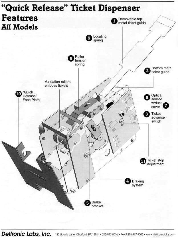
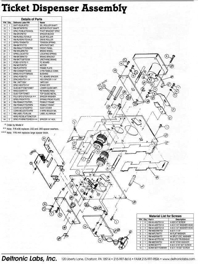
38 TICKET DISPENSER REFERENCE GUIDE Page 34
39 Page 35
40 Page 36
41 Page 37
42 Page 38
43 MAIN WIRING LITTLE SPEEDY Page 39
44 MAIN WIRING 1 LITTLE SPEEDY Page 40
45 MAIN WIRING 2 LITTLE SPEEDY Page 41
46 CONTROL WIRING LITTLE SPEEDY Page 42
47 CONTROL WIRING 1 LITTLE SPEEDY Page 43
48 POWER WIRING LITTLE SPEEDY Page 44
49 OPTIONAL WIRING LITTLE SPEEDY Page 45
50 DISCLAIMER OPERATOR WILL TAKE NOTE. BY ACCEPTING DELIVERY OF AND PLACING THIS HARDWARE AND LICENSED SOFTWARE INTO OPERATION, OPERATOR REPRESENTS AND WARRANTS THAT IT WILL ONLY OPERATE THE HARDWARE AND LICENSED SOFTWARE PROVIDED BY LAI GAMES IN COMPLIANCE WITH THE REGULATORY REQUIREMENTS OF THE COUNTRY, STATE, AND/OR MUNICIPALITY IN WHICH THE HARDWARE AND LICENSED SOFTWARE ARE USED AND/OR OPERATED. LAI GAMES HAS PROVIDED THIS HARDWARE AND LICENSED THE SOFTWARE ONLY FOR LEGITIMATE AND LEGAL USE, AND ANY USE OF THE HARDWARE AND LICENSED SOFTWARE IN A MANNER THAT VIOLATES ANY LAWS OF THE COUNTRY, STATE, AND/OR MUNICIPALITY IN WHICH THE HARDWARE AND LICENSED SOFTWARE ARE USED AND/OR OPERATED IS WHOLLY UNAUTHORIZED AND SHALL BE AT OPERATOR S SOLE AND COMPLETE RISK. Operator assumes any and all risk and liability for any civil or criminal legal claims or causes of action arising from the unauthorized use and/or operation of the provided hardware and licensed software, such improper and unauthorized use specifically including, but not limited to: (a) Operating or allowing the operation of the hardware and licensed software in a manner that violates the laws and regulations of the country, state, and/or municipality in which the hardware and licensed software are used or operated; (b) Assembling or causing the assembly of the hardware in a manner not authorized by or disclosed in this manual; (c) Any tampering with, changes to, or modifications of the licensed software that occur after the software leaves LAI GAMES factory that is not made by authorized LAI GAMES personnel and that is directly or indirectly caused by Operator; and (d) Any tampering with the computer chip/electronic programmable read only memory (EPROM) by or on behalf of Operator that directly or indirectly causes the tamper-indicating holographic seal on the computer chip/eprom to be broken or damaged in any way. LAI GAMES shall have no liability related to such improper and unauthorized use and/or operation of the hardware and licensed software, and Operator shall indemnify, defend, and hold LAI GAMES harmless for any claim or cause of action brought against LAI GAMES arising from Operator s or Operator s representative s improper and unauthorized use and/or operation of the hardware and licensed software. ANY IMPROPER AND UNAUTHORIZED USE SHALL COMPLETELY AND TOTALLY VOID ANY AND ALL WARRANTIES, BOTH EXPRESS AND IMPLIED, OF THE HARDWARE AND LICENSED SOFTWARE PROVIDED BY LAI GAMES.
51 WARRANTY LAI Games warrants its manufactured products for a period of 3 months inclusive of parts and labor from the date of sale. LAI Games exclusive obligation is to repair any item with any defects as a result of faulty workmanship or materials, providing the defective item or items of equipment are returned to the LAI GAMES distributor from which the machine was purchased. LAI Games shall have no obligation to make repairs necessitated by negligence or interference to any component by any unauthorized personal. This will automatically void any existing warranty. IF MAKING A WARRANTY CLAIM: (a) A Copy of the sales invoice must accompany the claim. (b) To and from Transport and freight costs are not covered by the warranty. (c) Warranty is not transferable with the sale of a machine from one owner to another. LAI Games sales@laigames.com
PLEASE NOTE: LAI Games
 PLEASE NOTE: Read this manual BEFORE operating the machine. Keep this manual for your reference. Go to www.laigames.com click on Operator Access to register your games and receive of future updates. LAI
PLEASE NOTE: Preliminary. LAI Games
 Preliminary PLEASE NOTE: Read this manual BEFORE operating the machine. Keep this manual for your reference. Go to www.laigames.com click on Support to register your games and receive of future updates.
PLEASE NOTE: Version LAI Games
 Version 1.4.2 PLEASE NOTE: Read this manual BEFORE operating the machine. Keep this manual for your reference. Go to www.laigames.com Click on Support to register your Game and receive future updates.
PLEASE NOTE: LAI GAMES V 1.3
 V 1.3 PLEASE NOTE: Read this manual BEFORE operating the machine. Keep this manual for your reference. Go to www.laigames.com click on Operator Access to register your games and receive of future updates.
LAI GAMES 2004
 www.laigames.com 1st Ed. SKILL July 2004 READ THIS MANUAL BEFORE OPERATING THE MACHINE. KEEP THIS MANUAL FOR YOUR REFERENCE. LAI GAMES Correspondence regarding this machine should be addressed to your
PLEASE NOTE: LAI GAMES V 3.1
 V 3.1 PLEASE NOTE: Read this manual BEFORE operating the machine. Keep this manual for your reference. Go to www.laigames.com click on Operator Access to register your games and receive of future updates.
LAI GAMES
 www.laigames.com READ THIS MANUAL BEFORE OPERATING THE MACHINE. KEEP THIS MANUAL FOR YOUR REFERENCE. LAI GAMES Correspondence regarding this machine should be addressed to your closest LAI GAMES office,
LAI GAMES READ THIS MANUAL BEFORE OPERATING THE MACHINE. KEEP THIS MANUAL FOR YOUR REFERENCE.
 www.laigames.com READ THIS MANUAL BEFORE OPERATING THE MACHINE. KEEP THIS MANUAL FOR YOUR REFERENCE. LAI GAMES Correspondence regarding this machine should be addressed to your closest LAI GAMES office,
PLEASE NOTE: LAI GAMES V 3.0
 V 3.0 PLEASE NOTE: Read this manual BEFORE operating the machine. Keep this manual for your reference. Go to www.laigames.com click on Operator Access to register your games and receive of future updates.
OPERATION & SERVICE MANUAL FOR FC 110 AC POWER SOURCE
 OPERATION & SERVICE MANUAL FOR FC 100 SERIES AC POWER SOURCE FC 110 AC POWER SOURCE VERSION 1.3, April 2001. copyright reserved. DWG No. FC00001 TABLE OF CONTENTS CHAPTER 1 INTRODUCTION... 1 1.1 GENERAL...
ABOUT SMOKIN' TOKEN EXTREME
 ABOUT SMOKIN' TOKEN EXTREME Operators distinguish Smokin Token as one of the great redemption success stories, and are now able to share in that unprecedented success for yet another generation. Smokin
SOCCERMANIA User manual
 User manual Contents General information - Introduction Page 3 General information - Safety Page 3 Waranty terms Page 4 Machine description Pages 5-6 Main Board description Pages 7-9 MP3 instalation Page
TABLE OF CONTENTS. PDF 文件使用 "pdffactory Pro" 试用版本创建
 TABLE OF CTENTS Version: 4.3-003 Time: 2008-3-5 SAFTTY INSTRUCTIS...1 INTRODUCTI...2 PACKAGING...2 ACCERSSORIES...2 TECHNICAL PARAMETERS...2 LOCATI REQUIREMENTS...2 PLAYING INSTRUCTIS...3 ADJUSTING THE
To Purchase This Game, Visit BMI Gaming Or Contact International Sales at (USA) The Simpsons Soccer
 The Simpsons Soccer") The Simpsons Soccer STANDARD OPERATING MANUAL Rev. 9-4-12 (Software Version: 07-30-12) Coastal Amusements, Inc. 1950 Swarthmore Ave. Lakewood, NJ 08701 +1 (732) 905-6662 sales@coastalamusements.com http://www.coastalamusements.com
The Simpsons Soccer STANDARD OPERATING MANUAL Rev. 9-4-12 (Software Version: 07-30-12) Coastal Amusements, Inc. 1950 Swarthmore Ave. Lakewood, NJ 08701 +1 (732) 905-6662 sales@coastalamusements.com http://www.coastalamusements.com
CONNECTOR (10PIN) BLACK BEARD PARTS SIDE
 BLACK BEARD PARTS SIDE") CONNECTOR (10PIN) PARTS SIDE SOLDER SIDE GND 1 GND GND 2 GND (*1) +5V 3 +5V +5V 4 +5V (*1) +12V 5 +12V +12V 6 +12V Ticket Dispenser Enable 7 (*2) Hopper SSR 8 GND 9 GND GND 10 GND (1) DC +5V 2A and DC
CONNECTOR (10PIN) PARTS SIDE SOLDER SIDE GND 1 GND GND 2 GND (*1) +5V 3 +5V +5V 4 +5V (*1) +12V 5 +12V +12V 6 +12V Ticket Dispenser Enable 7 (*2) Hopper SSR 8 GND 9 GND GND 10 GND (1) DC +5V 2A and DC
COASTAL AMUSEMENTS, INC, 1950 SWARTHMORE AVE LAKEWOOD, NJ (732)
") OPERATOR S MANUAL COASTAL AMUSEMENTS, INC, 1950 SWARTHMORE AVE LAKEWOOD, NJ 08701 (732) 905-6662 http://www.coastalamusements.com INTRODUCTION Subway Surfers is an amusement redemption game in which the
OPERATOR S MANUAL COASTAL AMUSEMENTS, INC, 1950 SWARTHMORE AVE LAKEWOOD, NJ 08701 (732) 905-6662 http://www.coastalamusements.com INTRODUCTION Subway Surfers is an amusement redemption game in which the
COASTAL AMUSEMENTS, INC, 1950 SWARTHMORE AVE LAKEWOOD, NJ (732)
") OPERATOR S MANUAL Version 1.1 COASTAL AMUSEMENTS, INC, 1950 SWARTHMORE AVE LAKEWOOD, NJ 08701 (732) 905-6662 http://www.coastalamusements.com INTRODUCTION Temple Run 2 is an amusement redemption game in
OPERATOR S MANUAL Version 1.1 COASTAL AMUSEMENTS, INC, 1950 SWARTHMORE AVE LAKEWOOD, NJ 08701 (732) 905-6662 http://www.coastalamusements.com INTRODUCTION Temple Run 2 is an amusement redemption game in
.VEGAS NIGHT. The following developer is responsible for the declaration: (Manual Version: VEG_INT _7B) VEG_INT _7B 1
 VEG_INT _7B 1") .VEGAS NIGHT. The following developer is responsible for the declaration: Astro Corp. 10F, No.111-1, HSING DE RD, SANCHUNG CITY, TAIPEI COUNTY, TAIWAN Telephone:+886-2-8511-0555 Facsimile:+886-2-8511-0556
.VEGAS NIGHT. The following developer is responsible for the declaration: Astro Corp. 10F, No.111-1, HSING DE RD, SANCHUNG CITY, TAIPEI COUNTY, TAIWAN Telephone:+886-2-8511-0555 Facsimile:+886-2-8511-0556
Operator Menus Guide Incredible Technologies, Inc. All Rights Reserved
 Operator Menus Guide 2014 Incredible Technologies, Inc. All Rights Reserved Operator Menus Guide OPERATOR MENUS NAVIGATING THE MENU SYSTEM The Operator Menus allow you to adjust the machine for your specific
CANARY AUDIO. Power Amplifier CA-309 OWNER S MANUAL. Handcrafted in California MADE IN USA
 CANARY AUDIO 300B Push-Pull Parallel Power Amplifier Mono Block Handcrafted in California CA-309 OWNER S MANUAL MADE IN USA Dear Customer: Please allow us to take this opportunity to thank you for purchasing
GOLDEN CITY (5 REELS 25 LINES VIDEO XVGA SLOT GAME)
") GOLDEN CITY (5 REELS 25 LINES VIDEO XVGA SLOT GAME) Golden City designs with the object of operating professional and amused game of casino, rather than making classic slot game. It s really extraordinary
GOLDEN CITY (5 REELS 25 LINES VIDEO XVGA SLOT GAME) Golden City designs with the object of operating professional and amused game of casino, rather than making classic slot game. It s really extraordinary
Puppy Jump Operations Manual
 Puppy Jump Operations Manual WARNING Be sure to read this Operation Manual before using your machine to ensure safe operation. 2013 Bob s Space Racers Incorporated 427 15 th Street, Daytona Beach, Florida
Operators Manual (Manual A)
") CD201 SINGLE COLUMN CARD DISPENSER Operators Manual (Manual A) Contents A1 Scope... 1 A2 Specifications... 1 A3 Installation... 2 3.1 Unpacking and inspection... 2 3.2 Opening and closing the door... 2
CD201 SINGLE COLUMN CARD DISPENSER Operators Manual (Manual A) Contents A1 Scope... 1 A2 Specifications... 1 A3 Installation... 2 3.1 Unpacking and inspection... 2 3.2 Opening and closing the door... 2
(SUBSINO CASINO GAME HIGH RESOLUTION SERIES)
") ALADDIN (SUBSINO CASINO GAME HIGH RESOLUTION SERIES) Discover the excitement of fast-hitting video slot plus two progressive jackpots. Players will be flying with the gliding carpet of Aladdin! Players
ALADDIN (SUBSINO CASINO GAME HIGH RESOLUTION SERIES) Discover the excitement of fast-hitting video slot plus two progressive jackpots. Players will be flying with the gliding carpet of Aladdin! Players
PLEASE READ ALL INSTRUCTIONS BEFORE OPERATING THIS MACHINE
 PLEASE READ ALL INSTRUCTIONS BEFORE OPERATING THIS MACHINE TRIGGER HAPPY IS AN EXCITING NEW SHOOTING GALLERY GUN GAME FROM FUN INDUSTRIES. THIS MACHINE IS DESIGNED TO DISPENSE 2 PRIZES AS WELL AS TICKET
R-Series R235LS 2-Channel Power Amplifier with Local Source Switching
 R-Series R235LS 2-Channel Power Amplifier with Local Source Switching User s Manual On Off R235LS POWER A MPLIFIER IMPORTANT SAFEGUARDS WARNING TO REDUCE THE RISK OF FIRE OR ELECTRIC SHOCK, DO NOT EXPOSE
STANDARD OPERATING MANUAL Rev
 STANDARD OPERATING MANUAL Rev. 5-31-12 (Software Version: 05-31-12) Coastal Amusements, Inc. 1950 Swarthmore Ave. Lakewood, NJ 08701 +1 (732) 905-6662 sales@coastalamusements.com http://www.coastalamusements.com
Standard PS-P61 Punch Stapler
 Standard PS-P61 Punch Stapler Instruction Manual Provided By http://www.mybinding.com http://www.mybindingblog.com PUNCH STAPLE PS-P61 Important Information - This manual is designed to help you to install,
PIRATES ISLAND (SUBSINO CASINO GAME XVGA SERIES)
") PIRATES ISLAND (SUBSINO CASINO GAME XVGA SERIES) This game takes a theme you already love Pirates Island - to the next level with new XVGA 5-reels and 9-lines of excitement. State-of-the-art graphics promote
PIRATES ISLAND (SUBSINO CASINO GAME XVGA SERIES) This game takes a theme you already love Pirates Island - to the next level with new XVGA 5-reels and 9-lines of excitement. State-of-the-art graphics promote
Opus 21 s80 Integrated Amplifier Owner's Manual
 Opus 21 s80 Integrated Amplifier Owner's Manual r e s o l u t i o n From all of us at Resolution Audio, thank you for choosing the Opus 21 s80 amplifier. We went to great lengths to design and produce
OWNER S MANUAL DANGER
 OWNER S MANUAL The actual product you have received may differ slightly from the illustration. DANGER To ensure safe operation of the product, be sure to read this Operation Manual before use. Keep this
С 800 CASSIDA C 800 HIGH SPEED COIN COUNTER
 С 800 CASSIDA C 800 HIGH SPEED COIN COUNTER This manual contains important information on safety measures and operational features. Please read it carefully before operating your coin counter, and keep
OWNERS AND SERVICE MANUAL 2001 INNOVATIVE CONCEPTS IN ENTERTAINMENT INC.
 OWNERS AND SERVICE MANUAL 2001 INNOVATIVE CONCEPTS IN ENTERTAINMENT INC. 10123 MAIN STREET, CLARENCE, NEW YORK 14031 SERVICE 716-759-0360 SALES 716-759-0370 FAX 716-759-0390 E MAIL play@icegame.com TABLE
Classic Series Public Address Amplifiers C10 & C20 Models
 Classic Series Public Address Amplifiers C10 & C20 Models Installation and Use Manual 2009 Bogen Communications, Inc. All rights reserved. Specifications subject to change without notice. 54-5978-01B 0901
OWNER S MANUAL DANGER
 OWNER S MANUAL The actual product you have received may differ slightly from the illustration. DANGER To ensure safe operation of the product, be sure to read this Operation Manual before use. Keep this
Wireless Z-Wave Control ZRP-100US Z-Wave Repeater USER MANUAL. Introduction
 Wireless Z-Wave Control ZRP-100US Z-Wave Repeater USER MANUAL Introduction Thank you for choosing ZRP-100 Z-Wave Repeater product! ZRP-100 is a Z-Wave repeater with best RF performance to repeat Z-Wave
CANARY AUDIO. EL34 Stereo Power Amplifier. Handcrafted in California CA-770 OWNER S MANUAL MADE IN USA
 CANARY AUDIO EL34 Stereo Power Amplifier Handcrafted in California CA-770 OWNER S MANUAL MADE IN USA Dear Customer: Please allow us to take this opportunity to thank you for purchasing this CANARY AUDIO
INTEGRATED HYBRID TUBE AMPLIFIER VT Model HYBRID TUBE AMPLIFIER
 INTEGRATED HYBRID TUBE AMPLIFIER Model VT-40.2 HYBRID TUBE AMPLIFIER OWNER S MANUAL Safety Instructions The lightning flash with the arrowhead symbol within an equilateral triangle is intended to alert
SI-125 Power Amplifier Manual 6205 Kestrel Road; Mississauga, Ontario; Canada; L5T 2A1 November 2016, Rev 0.5
 SI-125 Power Amplifier Manual 6205 Kestrel Road; Mississauga, Ontario; Canada; L5T 2A1 November 2016, Rev 0.5 Phone: (905) 564-0801 Fax: (905) 564-0806 www.telecor.com E:\T2-108\T2-M108-ABC\T2-M108-B.doc/AD
AV30MX-2 Operation Manual
 AV30MX-2 Operation Manual 1 Important safety instructions 1. Please read carefully prior to product installation or operation. 2. Read these instructions. 3. Keep these instructions. 4. Heed all warnings.
2015 RIGOL TECHNOLOGIES, INC.
 Service Guide DG000 Series Dual-channel Function/Arbitrary Waveform Generator Oct. 205 TECHNOLOGIES, INC. Guaranty and Declaration Copyright 203 TECHNOLOGIES, INC. All Rights Reserved. Trademark Information
Service Manual Innovative Concepts in Entertainment
 Service Manual Innovative Concepts in Entertainment 10123 Main Street Clarence, New York 14031 (716) 759-0360 www.icegame.com Table of Contents What s included 3 Safety and Warnings 4 Game Assembly 5-9
AMP SELECTOR Owner s Manual
 AMP SELECTOR Owner s Manual Version 1.0 VOODOO LAB AMP SELECTOR User s Manual Introduction The Voodoo Lab Amp Selector is the ultimate stand-alone tool for switching your guitar into multiple amplifiers.
Model S-520 Coin Counter / Sorter Operating Manual
 Model S-520 Coin Counter / Sorter Operating Manual Table of Contents Using the Product Safely... 2 About the Warning Stickers and Points of Warning/... 2 Warning.... 3. 4 Names of the Main Parts......
Keychain Radio Remote Control System
 Innovation in Mobility Keychain Radio Remote Control System Operator Manual 04/23/02 95-2002 RICON CORPORATION All Rights Reserved U.S. and foreign patents pending Printed in the United States of America
SHIRTS AND SKINS JUNIOR EDITION COASTAL AMUSEMENTS INC SWARTHMORE AVE LAKEWOOD, NJ TEL: FAX:
 SHIRTS AND SKINS JUNIOR EDITION COASTAL AMUSEMENTS INC. 1935 SWARTHMORE AVE LAKEWOOD, NJ 08701 TEL: 732-905-6662 FAX: 732-905-6815 W632 SHIRTS AND SKINS FUSE AT MAIN BOARDS F1, 20 mm 2A GATE MOTOR; F2,
The Circus. Manual Version: TC_US TC_US
 The Circus Manual Version: 2 Table of Contents Interface Interface & Button Layout p. 04 Setup Menu p. 05 Setup Password p. 06 Information p. 07 Data Setting p. 08 Confirm Reset p. 10 Bookkeeping p. 11
DL102 Counter Loop Amplifier
 DL102 Counter Loop Amplifier USER MANUAL MAN 234A Contents Overview...3 System Includes...3 Maintenance and Recycling Instructions...3 Safety Information...4 Quick Setup...5 Setup...6 Loop Amplifier...6
BO-01 Blackout. Operation & Service Manual. Version 1.1. * Read this manual before use
 BO-01 Blackout Operation & Service Manual Version 1.1 * Read this manual before use General Remark If you encounter any difficulties or if you need support on how to update and/ or install your Blackout
OPERATOR S MANUAL COASTAL AMUSEMENTS, INC, 1950 SWARTHMORE AVE LAKEWOOD, NJ (732)
") a mobile app to coin-op game OPERATOR S MANUAL COASTAL AMUSEMENTS, INC, 1950 SWARTHMORE AVE LAKEWOOD, NJ 08701 (732) 905-6662 http://www.coastalamusements.com INTRODUCTION Rail Rush is an amusement redemption
a mobile app to coin-op game OPERATOR S MANUAL COASTAL AMUSEMENTS, INC, 1950 SWARTHMORE AVE LAKEWOOD, NJ 08701 (732) 905-6662 http://www.coastalamusements.com INTRODUCTION Rail Rush is an amusement redemption
SYSTEM OPERATING CONTROLS
 SYSTEM OPERATING CONTROLS Master Station Controls 1 END CALL: Ends intercom communication and returns system to audio source. 2 DOOR TALK: Initiates intercom communication to the door speakers. 3 INSIDE/PATIO:
PROGRESSIVE JACKPOT MARQUEE
 PROGRESSIVE JACKPOT MARQUEE 1 FACTORY CONTACT INFORMATION BAY TEK GAMES INC. Pulaski Industrial Park 1077 East. Glenbrook Drive Pulaski, WI 54162 USA JOIN OUR SERVICE FIRST NETWORK! This free service is
Installation and Operation Manual MSI. Multi-Sensor Interface Hub. Interface Module for all Sensors Network and Wireless CAUTION
 Installation and Operation Manual MSI Multi-Sensor Interface Hub Interface Module for all Sensors Network and Wireless CAUTION This equipment complies with the limits for a Class B digital device, pursuant
TABLE OF CONTENTS 1 BRIEF INSTRUCTION NOTICE... 1
 TABLE OF CONTENTS Ver:1.01 Time:2010-12-16 1 BRIEF INSTRUCTION... 1 2 NOTICE... 1 2-1. SAFTTY INSTRUCTIONS...1 2-2. NOTICE FOR OPERATION...1 3 ACCESSORIES... 1 4 HOW TO PLAY... 2 5 TECHNICAL PARAMETERS...
INSTALLATION INSTRUCTIONS
 INSTALLATION INSTRUCTIONS FLIP Flip-Down LCD Mount NORTH AMERICA 3130 East Miraloma Avenue Anaheim, CA 92806 USA USA and Canada Phone: 800-368-9700 Fax: 800-832-4888 EUROPE Swallow House, Shilton Industrial
AQ-SWA8-1BT - ACTIVE SUBWOOFER USER / INSTALLATION MANUAL. with Bluetooth & Full Range Speaker Outputs
 AQ-SWA8-1BT - ACTIVE SUBWOOFER with Bluetooth & Full Range Speaker Outputs USER / INSTALLATION MANUAL PLEASE READ THIS INSTRUCTION MANUAL BEFORE INSTALLATION AND OPERATION Table of Contents 1 Introduction...
ApexDesk Assembly Guide
 ELECTRIC HEIGHT-ADJUSTED SIT TO STAND DESK ApexDesk Assembly Guide REV-1507C Table of Contents CAUTION, USE & LIABILITY... 3 PARTS & HARDWARE LIST... 4 PARTS / COMPONENT DIAGRAMS... 5 ASSEMBLY INSTRUCTIONS...
CR31. Companion. Instruction Manual
 CR31 Companion Instruction Manual 910-244700-001 IMPORTANT SAFETY INSTRUCTION PLEASE READ CAREFULLY ALL THE FOLLOWING IMPORTANT SAFEGUARDS THAT ARE APPLICABLE TO YOUR EQUIPMENT 1. Read Instructions - All
HTA125A/250A. Power Amplifiers. Installation & Use Manual
 HTA125A/250A Power Amplifiers Installation & Use Manual Specifications subject to change without notice. 2010 Bogen Communications, Inc. All rights reserved. 54-5832-04B 1011 NOTICE: Every effort was made
WRM-10 TM TRANSFORMER WINDING RESISTANCE METER
 WRM-10 TM TRANSFORMER WINDING RESISTANCE METER USER S MANUAL Vanguard Instruments Company, Inc. 1520 S. Hellman Ave. Ontario, California 91761, USA TEL: (909) 923-9390 FAX: (909) 923-9391 June 2009 Revision
léìë=on ëpm=fåíéöê~íéç=^ãéäáñáéê lïåéêdë=j~åì~ä êéëçäìíáçå
 léìë=on ëpm=fåíéöê~íéç=^ãéäáñáéê lïåéêdë=j~åì~ä êéëçäìíáçå From all of us at Resolution AV, thank you for choosing the Opus 21 s30 amplifier. We went to great lengths to design and produce an integrated
Planishing hammer stand For use with SKU Planishing hammer
 Planishing hammer stand For use with SKU 94847 Planishing hammer Model 96300 Assembly And Operation Instructions Please Note: Planishing Hammer not included with Stand. Due to continuing improvements,
MaxLite Linear Strip ECO Series
 General Safety Information To reduce the risk of death, personal injury or property damage from fire, electric shock, falling parts, cuts/abrasions, and other hazards read all warnings and instructions
C2000 Operational Manual
 C2000 Operational Manual Document #101-0009 1 3/09/05 TABLE OF CONTENTS I. INTRODUCTION... 4 Options... 4 II. OPERATION...5-6 Vend Switches... 5 Configuration Switches... 5 LED... 5 Resetting... 6 III.
FISHIN HOLE GAME MANUAL Rev. A
 FISHIN HOLE GAME MANUAL Rev. A WARNING Be sure to read this Operation Manual before using your machine to ensure safe operation. 2013 Bob s Space Racers Incorporated 427 15 th Street, Daytona Beach, Florida
~ Pizzeria ~ The following developer is responsible for the declaration: Astro Corp.
 ~ Pizzeria ~ The following developer is responsible for the declaration: Astro Corp. 10F, No. 111-1 HSING DE RD, SANCHUNG CITY, TAIPEI COUNTY, TAIWAN Tel:+886-2-8511-0555 Fax:+886-2-8511-0556 E-mail:sales@astrocorp.com.tw
User Manual. Flooring Removal Machine (Patent Pending) Maintenance and Operating Instructions
 Maintenance and Operating Instructions") User Manual Flooring Removal Machine (Patent Pending) Maintenance and Operating Instructions Copyright 2012 by Carpet Concepts LLC. All Rights Reserved. For technical questions or replacement parts please
User Manual Flooring Removal Machine (Patent Pending) Maintenance and Operating Instructions Copyright 2012 by Carpet Concepts LLC. All Rights Reserved. For technical questions or replacement parts please
Model CC4041. CC Series Amplifier. Installation and Use Manual
 BASS 0 TREBLE 0-12 +12-12 +12 INPUT 1 INPUT 2 INPUT 3 INPUT 4 PEAK SIGNAL POWER POWER CC Series Amplifier Model CC4041 Installation and Use Manual 2012 Bogen Communications, Inc. All rights reserved. Specifications
UPLIFT 2-Leg Height Adjustable Standing Desk
 UPLIFT -Leg Height Adjustable Standing Desk Also watch our assembly video http://bit.ly/9ywwh DIRECTIONS FOR ASSEMBLY AND USE TABLE OF CONTENTS PAGE Safety and Warnings Usage Parts List Assembly Instructions
INSTRUCTION MANUAL. 1 Light Exterior Wall Lantern. Home Depot SKU (UPC ) Home Depot SKU (UPC ) (Prairie Bronze)
 Home Depot SKU (UPC ) (Prairie Bronze)") INSTRUCTION MANUAL 1 Light Exterior Wall Lantern Home Depot SKU 477405 (UPC 718212230107) Home Depot SKU 495682 (UPC 718212230282) (Prairie Bronze) Page 1 Thank you for purchasing this Hampton Bay exterior
INSTRUCTION MANUAL 1 Light Exterior Wall Lantern Home Depot SKU 477405 (UPC 718212230107) Home Depot SKU 495682 (UPC 718212230282) (Prairie Bronze) Page 1 Thank you for purchasing this Hampton Bay exterior
Page 1 T O O L S A N D M AT E R I A L S R E Q U I R E D. 1. Screwdriver 2. Carpenter's level 3. Electrical Tape PA R T S L I S T. A.
 T O O L S A N D M AT E R I A L S R E Q U I R E D 1. Screwdriver 2. Carpenter's level 3. Electrical Tape PA R T S L I S T A. Cabinet B. Wood Screw X4 C. Plastic wire connector x3 Page 1 I M P O R TA N T
ATTENTION! There is only ONE set of keys per machine. Locks and keys CANNOT be replaced. PLEASE keep your keys in a safe place.
 Instruction Manual ATTENTION! This manual is for reference only. Each machine will be a little different depending upon model and manufacturer. All slot machines essentially program and play the same.
INSTALLATION INSTRUCTIONS
 INSTALLATION INSTRUCTIONS Compact Power Amplifier NORTH AMERICA 3130 East Miraloma Avenue Anaheim, CA 92806 USA USA and Canada Phone: 1.800.368.9700 Fax: 1.800.832.4888 Other Locations Phone: (001).714.632.7100
OPERATING MANUAL. Rev
 OPERATING MANUAL Rev. 05-17-10 (Software Version: OPER515) Coastal Amusements, Inc. 1935 Swarthmore Ave. Lakewood, NJ 08701 (732) 905-6662 http://www.coastalamusements.com INTRODUCTION The coin-operated
VAS35P / VAS36P SHAKER LOUDSPEAKER SYSTEMS
 VAS35P / VAS36P SHAKER LOUDSPEAKER SYSTEMS Thank you for your interest in VM Audio products. Our goal is to enhance your listening experience. The Shaker Series was designed as the economical solution
Shelti, Inc. 333 Morton Street Bay City, MI Phone Fax. Bayside Dollar Bill Acceptor Pool Table Manual & Instructions
 Shelti, Inc. 333 Morton Street Bay City, MI 48706 989-893-1739 Phone 989-893-1809 Fax Bayside Dollar Bill Acceptor Pool Table Manual & Instructions Contents Section-1 Introduction Bayside DBA Pool Table
impact VC-500LR Monolight INSTRUCTIONS
 impact lighting equipment and accessories VC-500LR Monolight INSTRUCTIONS Congratulations on your purchase of the Impact VC-500LR Monolight. We feel that it will contribute much to your photographic skill
UPLIFT 2-Leg Height Adjustable Standing Desk - For use with UPLIFT Eco and Eco Curve desktops -
 UPLIFT -Leg Height Adjustable Standing Desk - For use with UPLIFT Eco and Eco Curve desktops - DIRECTIONS FOR ASSEMBLY AND USE TABLE OF CONTENTS Please Note PAGE Safety and Warnings Usage Parts List Assembly
UPLIFT 3-Leg Desk Instructions for. Solid Wood Desktops. pictured: 3-leg desk; solid-wood top, with right hand return TABLE OF CONTENTS
 UPLIFT 3-Leg Desk Instructions for Solid Wood Desktops pictured: 3-leg desk; solid-wood top, with right hand return TABLE OF CONTENTS PAGE 1 Safety and Warnings 2 2 Usage 2 3 Parts List 3 4 Assembly Instructions
Big Bang. B B O w n e r s M a n u a l. Power Amplifiers. SpeakerCraft BB2125 POWER ACTIVE PROTECTION L
 Big Bang Power Amplifiers SpeakerCraft BB2125 ACTIVE POWER PROTECTION L R B B 2 1 2 5 O w n e r s M a n u a l SAFETY INSTRUCTIONS APPLICABLE FOR USA, CANADA OR WHERE APPROVED FOR USAGE CAUTION: To reduce
15 Planer Stand. Model Due to continuing improvements, actual product may differ slightly from the product described herein.
 15 Planer Stand Model 96316 Assembly And Operation Instructions Due to continuing improvements, actual product may differ slightly from the product described herein. 3491 Mission Oaks Blvd., Camarillo,
Rock Sounders. Weatherproof Wireless 900MHz Speaker System. User Guide. Model no.: GDI-AQRCK400 / AQRCK41
 Rock Sounders Weatherproof Wireless 900MHz Speaker System User Guide Model no.: GDI-AQRCK400 / AQRCK41 Please read before using the equipment IMPORTANT: Please read your User s Guide before using your
Series 3000 Model R-107A
 Series 3000 Model R-107A DUAL TONE SENDER INSTRUCTION MANUAL Monroe Electronics 100 Housel Ave Lyndonville NY 14098 800-821-6001 585-765-2254 fax 585-765-9330 monroe-electronics.com Printed in USA Copyright
AN AMUSEMENT/REDEMPTION VIDEO GAME (Revision: ) STANDARD VERSION
 STANDARD VERSION") AN AMUSEMENT/REDEMPTION VIDEO GAME (Revision: 09-10-12) STANDARD VERSION COASTAL AMUSEMENTS, INC. 1950 SWARTHMORE AVE LAKEWOOD, NJ 08701 (USA) TEL: 01-732-905-6662 FAX: 01-732-905-6815 E-MAIL: sales@coastalamusements.com
AN AMUSEMENT/REDEMPTION VIDEO GAME (Revision: 09-10-12) STANDARD VERSION COASTAL AMUSEMENTS, INC. 1950 SWARTHMORE AVE LAKEWOOD, NJ 08701 (USA) TEL: 01-732-905-6662 FAX: 01-732-905-6815 E-MAIL: sales@coastalamusements.com
Installation & User Guide. For Powering Distributed Audio Systems A45-X2 TWO CHANNEL AMPLIFIER
 Installation & User Guide For Powering Distributed Audio Systems TWO CHANNEL AMPLIFIER A45-X2 A45-X2 TWO CHANNEL AMPLIFIER TABLE OF CONTENTS Features...1 Product Overview...2 Package Contents...4 Preparing
A VIDEO REDEMPTION/AMUSEMENT GAME (Revision: )
") A VIDEO REDEMPTION/AMUSEMENT GAME (Revision: 02-15-08) COASTAL AMUSEMENTS, INC. 1935 SWARTHMORE AVE LAKEWOOD, NJ 08701 (USA) TEL: 01-732-905-6662 FAX: 01-732-905-6815 E-MAIL: sales@coastalamusments.com
A VIDEO REDEMPTION/AMUSEMENT GAME (Revision: 02-15-08) COASTAL AMUSEMENTS, INC. 1935 SWARTHMORE AVE LAKEWOOD, NJ 08701 (USA) TEL: 01-732-905-6662 FAX: 01-732-905-6815 E-MAIL: sales@coastalamusments.com
Owner s Manual & Safety Instructions
 Owner s Manual & Safety Instructions Save This Manual Keep this manual for the safety warnings and precautions, assembly, operating, inspection, maintenance and cleaning procedures. Write the product s
Model 5100F. Advanced Test Equipment Rentals ATEC (2832) OWNER S MANUAL RF POWER AMPLIFIER
 OWNER S MANUAL RF POWER AMPLIFIER") Established 1981 Advanced Test Equipment Rentals www.atecorp.com 800-404-ATEC (2832) OWNER S MANUAL Model 5100F RF POWER AMPLIFIER 0.8 2.5 GHz, 25 Watts Ophir RF 5300 Beethoven Street Los Angeles, CA 90066
Established 1981 Advanced Test Equipment Rentals www.atecorp.com 800-404-ATEC (2832) OWNER S MANUAL Model 5100F RF POWER AMPLIFIER 0.8 2.5 GHz, 25 Watts Ophir RF 5300 Beethoven Street Los Angeles, CA 90066
Model CC4052. CC Series Amplifier. Installation and Use Manual
 CC Series Amplifier Model CC4052 Installation and Use Manual 2012 Bogen Communications, Inc. All rights reserved. Specifications subject to change without notice. 54-2216-01A 1303 NOTICE: Every effort
A Channel Amplifier
 Installation Manual A2150 2 Channel Amplifier Table of Contents Installation Requirements and Recommendations 1 What s included 1 Speaker Wire Recommendations 1 Setup 2 Rack Mounting 2 Individually Protected
Schooners II. Weatherproof Wireless 900MHz Speaker System. User Guide. Model no.: GDI-AQSHR200 / AQSHR21
 Schooners II Weatherproof Wireless 900MHz Speaker System User Guide Model no.: GDI-AQSHR200 / AQSHR21 IMPORTANT: Please read your User s Guide before using your system INTRODUCTION Your SCHOONERS II speaker
CM3000. Operator s Manual. ChangeMaker. Seaga Manufacturing, Inc. 700 Seaga Drive Freeport, IL USA
 CM3000 ChangeMaker Operator s Manual Seaga Manufacturing, Inc. 700 Seaga Drive Freeport, IL USA 61032 www.seagamfg.com INTRODUCTION Congratulations on the purchase of your new ChangeMaker. This ChangeMaker
CHUCK E. CHEESE S MATCH GAME
 CHUCK E. CHEESE S MATCH GAME PLAYING THE GAME Chuck E. Cheese s Match Game is a memory match game for one player. The player is shown nine curtains which reveal five different characters: Chuck E. Cheese,
How to install your ecobee Switch+
 How to install your ecobee Switch+ Warning Installing this product involves handling high voltage wiring. Each step of the enclosed instructions must be followed carefully. To avoid fire, personal injury,
8' HOT SHOT SKEEBALL TABLE ASSEMBLY INSTRUCTIONS
 8' HOT SHOT SKEEBALL TABLE ASSEMBLY INSTRUCTIONS NG2015 THANK YOU! Thank you for purchasing this product. We work around the clock and around the globe to ensure that our products maintain the highest
INSTRUCTION MANUAL. MODEL: Vintage 60R. Vintage Series Guitar Amplifi er
 INSTRUCTION MANUAL MODEL: Vintage 60R Vintage Series Guitar Amplifi er 2 INTRODUCTION Thank you for choosing this Johnson amplifier. Please read this manual carefully and completely before operating your
HAND HELD SAW W MILL
 HAND HELD SAW W MILL 92247 ASSEMBLY AND OPERATING INSTRUCTIONS 3491 Mission Oaks Blvd., Camarillo, CA 93011 Visit our Web site at http://www.harborfreight.com Copyright 2004 by Harbor Freight Tools. All
To Purchase This Item, Visit BMI Gaming (800)
") FACTORY CONTACT INFORMATION Our Vision: We aspire to be the best in the world at developing and manufacturing coin operated games for our customers. BAY TEK GAMES INC. Pulaski Industrial Park 1077 East
FACTORY CONTACT INFORMATION Our Vision: We aspire to be the best in the world at developing and manufacturing coin operated games for our customers. BAY TEK GAMES INC. Pulaski Industrial Park 1077 East
Installation & Operation Manual SAGA1-K Series Industrial Radio Remote Control
 Installation & Operation Manual SAGA1-K Series Industrial Radio Remote Control Gain Electronic Co. Ltd. Table Of Contents Safety Considerations ------------------------------------------------------------2
Angle Grinder. Model Visit our website at:
 Angle Grinder Safety Guard Model 45921 Installation Instructions Note: Cutting Blade and Angle Grinder sold separately. Visit our website at: http://www.harborfreight.com Read this material before using