Reactive Cooperation of AIBO Robots. Iñaki Navarro Oiza
|
|
|
- Norman Gray
- 6 years ago
- Views:
Transcription
1 Reactive Cooperation of AIBO Robots Iñaki Navarro Oiza October 2004
2 Abstract The aim of the project is to study how cooperation of AIBO robots could be achieved. In order to do that a specific problem, in which two robots have to pass the ball between them, was introduced. To cooperate, the robots must be able to communicate, therefore a suitable module was developed. In order to design the solution there was the need for an analysis of the existing framework used by Team Chaos in RoboCup. It was found that self-localization module was not functioning sufficiently well. This made it difficult to create a deliberative solution due to the lack of an environment map. Therefore a reactive approach was taken. While performing the passes each of the robots had a specific role: receiver or kicker. This role was decided taking into account, among other things, the information received from the other robot. Several experiments were undertaken investigating how effectiveness at the given task depends on the type and amount of shared information. Four solutions were implemented and their results compared. It has been shown that given the circumstances the robots may cooperate with reasonable accuracy.
3 Contents 1 Introduction The Robots The Environment The TCC Framework Vision Module Communication Module Behavior Module WorldState Module Tekkotsu Module Cooperation Goal of the Project Analysis of the TCC Framework Vision Segmentation Object Recognition Movement of the Head Localization Behavior Kicks Conclusions Code of the Analysis Communication Module Description and Implementation Limitations Code of the Communication Module Passing the Ball Problem Definition of the Problem Solution for the problem Expected Results Basic Behaviors Go To Object Behavior Go Around Object Behavior Align Object With Object Behavior Finite State Machines Object Oriented Implementation
4 4.4.2 Find and Look for Ball FSM Go and Align FSM Kick FSM Kicker FSM Receiver FSM Searcher FSM Main Pass Ball FSM Relationship Between the FSMs and the Basic Behaviors The Roles of the robots Deciding the roles by stigmergy without any communication Deciding the roles by exchanging the distance to the ball Deciding the roles taking in account the own perception with communication Fixed Roles, without communication Without taking in account the perceptions, exchanging the roles by token passing General Results of the Investigation Code of the solution Conclusions and Future Work 56 Bibliography 58 A Segmented Images 60 B Object Recognition Statistics 66 C Localization Statistics 82 D Measures of the Kicks 86 E Glossary of Constants of the Behaviors 90 2
5 Chapter 1 Introduction The aim of the project is to define and solve some problems of cooperation between robots. The robots used are AIBO ERS-7. They interact in a soccer environment, one that is used in the RoboCup [1] competition. RoboCup is a robot conference and tournament in which teams of different universities and nationalities participate. There are different leagues, each with its own rules, for different types of robots. In the four-legged league the teams are formed by AIBO robots, the same ones as the used in this project. The rest of this Chapter describes the robots, the environment and the framework used. It also gives some notions about cooperation and explains the goal and scope of the project. The framework used was very new and no documentation or specification was provided. That is the reason why the first step was analysis and evaluation. Those are explained in Chapter 2. The robots, in order to cooperate, need a communication facility. No such module was available in the framework, so it had to be developed. The details are shown in Chapter 3. In Chapter 4 the Ball Passing problem is presented and the proposed solutions and their results discussed. 1.1 The Robots The robots used in the problem are two ERS-7 [2, 3], the last generation of the AIBO Robots developed by Sony Corporation. ERS-7, as the rest of the AIBO family, is a four legged robot with the appearance of a dog. It is around 20 cm high, 18 cm wide and 32 cm long. Its head as well as each leg has three degrees of freedom. In addition to that the robot has a tail and two ears that can be moved, although it is mainly useful for debugging purposes. The other actuators are LEDs and a speaker. The main sensor of the robot is a CMOS color camera, with a resolution of 416x320 pixels, located in the head. AIBO also posses a set of infrared sensors in order to measure distances, placed in the chest and in the head. In addition 3


6 it has an acceleration sensor for all three axes. Other inputs are a pair of microphones and some buttons for interaction with humans. It has Wireless LAN capabilities to communicate with the computer and other robots. The different parts of the robot can be seen in Figure 1.1. Figure 1.1: Different parts of ERS-7. The robots are white and grey, but for easier detection by image processing routines, they were dressed with red patches similar to the official ones of RoboCup. In Figure 1.2 a picture of the dressed robot can be seen. 1.2 The Environment The environment where the robots act is just like the one used officially in RoboCup. The Robot World Cup Initiative is a group of robotic activities 4
![Figure 1.2: One of the ERS-7 used, with the red patches attached. like conferences and competitions held every year [1, 4] and attended by different universities from all around the world.](/docs-images/75/72190049/images/7-0.jpg "It aims to promote the research in robotics by defining a benchmark: making robots to play soccer.")
7 Figure 1.2: One of the ERS-7 used, with the red patches attached. like conferences and competitions held every year [1, 4] and attended by different universities from all around the world. It aims to promote the research in robotics by defining a benchmark: making robots to play soccer. In the competition part of RoboCup there are many leagues: Simulation, Small Size, Middle Size and Four Legged, among others. The field used in this project and also the ball are the same as the ones used in the Four Legged League. The football field is 420 cm long and 270 cm wide. It is surrounded by an inner small white wall of 10 cm height to avoid that the robots go out of the field. There is an outer white wall of 1 m high to avoid that the robots see things from outside. The floor is a green carpet. One of the nets is yellow and the other blue. There are also four landmarks, one in each corner of the field, made of a combination of two colors: pink and blue or pink and yellow. They are placed in predefined positions to allow the robots to localize themselves. The only other object in the environment, except the robots themselves, is an orange ball, 5 cm of radius. To make vision and object recognition easier (or at all feasible) objects are uniquely colored. In Figure 1.3 a schematic of the field can be seen. A photo of the field is shown in Figure 1.4. As it will be said in Chapter 4 only the ball and the other robot will be considered and used in the Ball Passing problem, so the rest of the objects of the environment will not be important. 1.3 The TCC Framework TCC Framework is the software framework created by the members of Team Chaos Challenges (TCC) and gets the name from that. TCC is a part of Team Chaos, formed by students and professors of Lund University and Blekinge Institute of Technology. TCC have participated this year in the Challenges part of RoboCup This framework was build from scratch in order to participate in this competition. The Framework is not only to be used in the RoboCup but also in other projects like the one presented in this report. 5

![The TCC Framework is also based on Tekkotsu [7] that is another framework for AIBO, developed by Carnegie Mellon University.](/docs-images/75/72190049/images/8-1.jpg "Tekkotsu provides the low level interface with the robot in order to get information from it and order actions. In Figure 1.")
8 Figure 1.3: Schematic of the field. Figure 1.4: Half part of the field. The Framework is based on the OPEN-R SDK [3, 5, 6] and the Aperios Operating System [3] provided by Sony to program the different Sony robots like the AIBO ERS-7. The TCC Framework is also based on Tekkotsu [7] that is another framework for AIBO, developed by Carnegie Mellon University. Tekkotsu provides the low level interface with the robot in order to get information from it and order actions. In Figure 1.5 the relationship between Aperios, OPEN-R, Tekkotsu and TCC Framework is shown. The Framework consists of 4 modules (Tekkotsu, Vision, Communication and Behavior) that operate in a Token Ring architecture, plus a fifth module called WorldState that contains all the information concerning the environment 6

9 Figure 1.5: Relationship between Aperios, OPEN-R, Tekkotsu and TCC. and the robot that can be accessed by the others. There exists yet another module that operates at a lower frequency and is in charge of the localization. This module can be disconnected when the localization is not used. The other modules work cyclically: when is the turn for one of them it gets WorldState, when it is done it leaves WorldState with the new data and passes the token to the next module. The loop as it can be seen in Figure 1.6 takes the following order: Tekkotsu, Vision, Communication, Behavior and finally Tekkotsu again. Communication Get Set Vision Set Get World State Get Set Behavior Set Get Tekkotsu Figure 1.6: TCC Framework Modules (Without the Localization Module). 7
10 1.3.1 Vision Module The Vision Module takes the sensory information from the WorldState and processes it. The main task is the recognition of the objects made in two steps: first the Image Segmentation, and after that the Object Recognition. Image Segmentation is a process in which the value of the pixels of the image are transformed from the original range of values to a very reduced one. In this case the segmentation has as results the colors used in the RoboCup competition. In addition the result is given as blobs, that is groups of pixels with the same color. The segmentation is done using the SRG algorithm [8] of Team Sweden. The inputs of the Object Recognition are the results of the Image Segmentation. The aim of this module is to identify the different objects in the environment (nets, other robots and landmarks) and estimate their position. Once an object is identified its position is estimated taking into account the place of the blob in the images, its size and the position of the head when the image was taken. For each object the information resulting from Object Recognition is the following: Distance The distance from the center of the robot to the center of the observed object (expressed in mm). Theta The horizontal angle from the center of the robot to the center of the object (expressed in radians). Epsilon The vertical angle from the center of the robot to the center of the object (expressed in radians). Confidence A value between 0 and 1 that gives information about how sure it is that the object is there. In the frame that the object is seen Confidence is set to 1. When time passes this value is decreased. When the value reaches 0 there is no certainty at all that the object is there any more. Accuracy Is a value between 0 and 1 that gives an idea of how much position error is expected. All these results are placed in WorldState so that other modules can make use of them. The Vision Module is also in charge of taking the information from the infrared sensors a preprocessing it. In addition it has the responsibility of the head movements Communication Module This module is responsible for the communication between the different robots and the computer and among the robots. It is explained in Chapter 3. 8
11 1.3.3 Behavior Module The Behavior Module takes the information produced by the Vision Module and the one stored in the received messages in order to take different actions. These actions as will be explained in Chapter 4 are mainly done by Finite State Machines and some basic behavior functions. The different actions are performed by modifying some properties of the robot present in the WorldState: Related to the movement of the head: setpan Sets the pan angle of the Head overwriting the desired position given by vision. settilt Sets the tilt angle of the head overwriting the desired position given by vision. setnod Sets the nod angle of the head overwriting the desired position given by vision. Object.Importance This value tells Vision Module the importance of every object. Then Vision will move the Head according to it. The value must be between 0 (not important) and 1 (most important). When one object has importance of 1 and the rest 0 the Vision makes the head to move until it sees that object, and then stays all the time looking at it. Related to the movement of the robot: Speed Gives the velocity of the translation movement. Must be a value between 0 (stop) and 1 (maximum velocity) Alpha Tells the angle of the translation movement, expressed in radians between 0 and 2π. 0 Means forward and π backwards Spin Tells the robot the rotational velocity. Between -1 and means maximum velocity clockwise, 1 maximum counterclockwise and 0 no rotational movement. Related with two low level filters that the robot has to avoid obstacles: CollisionDetection When it is set to true, if the infrared sensor of the chest finds something in front of it, then it makes the robot to turn around to avoid the obstacle. The actions given by Speed, Spin and Alpha are not taken in account. It can be very useful when the robot gets stuck against the boundary wall. ObstacleAvoidance This Filter is a little more complex. It makes the robot to go around an object, when the robot founds an object in front of itself then turns around the object. A list of the objects to avoid must be provided. Related to their types of actions: WagTail If it is set to true it moves the tail. If false is stopped. 9
12 FlapEars If it is set to true it moves the ears. If false is stopped. Switch LEDs The LEDs are controlled with some variables of World- State WorldState Module The WorldState holds all the information concerning the environment and the robot so the different modules can share it. The data contained in WorldState is: sensor information, processed sensor information, the actions to take, the messages to send and received, etc Tekkotsu Module This module makes two things. First it reads the WorldState and moves the effectors in the appropriate way. Then it reads the sensor information and copies it to WorldState so that any module can read it. It is, as it was said before, the only interface with the robot. More information about the Framework can be found in Chapter 2 were the different features of it are analyzed. 1.4 Cooperation When two or more robots coexist in the same environment it can be said that it is a multi-robot system, but that does not mean that it is a cooperative system. There can be two robots performing different tasks and having no idea of the existence of the other. Cooperation occurs when some robots work together to perform a common task. It is not necessary that they know about the existence of the others. If a robot knows about the existence of the other it can be said that it has the Awareness property. A robot with this last property can be coordinated or not. Coordination occurs when the actions performed by each robot take in account the actions executed by the other, this does not mean that communication needs to take place [9]. In this project the robots cooperate since the passing ball is a common task. They are also aware since they know of the existence of the other robot. In addition, as it will be shown in future sections, they are coordinated. There can be cooperation and even coordination without communication. In coordination without communication robots coordinate by making use of stigmergy, this is they know about the other and decide their actions just by perceiving the environment [9, 10, 11]. Some experiments designed to solve the problem work with communication, others do without it. Iocchi [9] and Murphy [12] divide the groups of robots in homogeneous, those in which every robot has the same structure (both in a hardware and software 10
13 perspective), and heterogeneous when at least one of the robots has a different property than the others. In this problem the robots are the same and also their software, so they are homogeneous. They do another classification: distributed and centralized systems. Centralized are those in which there is one robot or computer that makes decisions for others. In distributed ones, as in this project, each robot takes its own decisions. One of the problems of multi-robots system that Murphy [12] lists is interference. Having more than one robot makes the possibility that they interfere with each other making the success more difficult. This was observed in the experiments. 1.5 Goal of the Project Many types of different cooperation problems could be defined: cooperative movement of objects, searching for objects, passing the ball from one robot to the other, etc. After much deliberation, due to the requirements of those problems, the Ball Passing was chosen. Cooperative movement of objects would need from vision module the recognition of those possible objects, and it was not available. Searching for objects in a cooperative way needs a self-localization facility that, as it will be shown in Chapter 2, is not working sufficiently well for such a purpose. The Ball Passing problem may be formulated as follows: there are two robots on the field. At first both have to find the ball, and after that they should start to make passes from one to the other. In this thesis it was intended to define, solve and analyze a family of such problems, varied by different amount and type of information shared. 11
14 Chapter 2 Analysis of the TCC Framework In order to do the experiments with cooperation between the AIBO robots, more exactly how the Ball Passing problem, it was necessary to know the quality of the TCC Framework. In a design process analysis is always present in order to identify the weaknesses of the approach [13]. Statistics must be taken because two measures are never the same in a dynamic environment due to the complexity of robot-environment interaction. Because of the early state of the Framework not everything was working perfectly. In addition, no tests of its capabilities have been made. In order to continue with the behavior part of the project it was necessary to know how Vision, Localization and the basic behaviors worked. The previous experience was that while working with the Framework, if something failed it was very difficult to localize the source the problem (Segmentation, Object Recognition, Localization). It was really important to know whether the Localization worked and to what extent, because in order to do some kind of cooperation the self localization is extremely important. Some of the objects in the environment, as Landmarks and Nets, were analyzed, even though finally they were not used at all in the final solution of the problem. In the next sections the analysis of the different parts of the Framework is presented. 2.1 Vision Segmentation The most basic step of Vision is the Segmentation. If it is not working properly then the Recognition will not work, and not Localization, and so on. The segmentation used is SRG Segmentation from Team Sweden (based on region 12
15 growing) that has been used before without problems. So the only thing remaining to be tested was to check if the current color tables were working properly. In order to do it a total of 85 frames of the field were taken from different places and of the different objects and colors of the environment. The images are correctly segmented with all the defined colors identified in most of the frames. Sometimes when an object is near the borders or corners of the frame is not properly segmented. The reason is that the image got from the camera is darker on the borders. This is not a big problem since a color that is in the center and also in the borders is expanded from the center to the outer region most of the times. Then only small objects close to the borders are sometimes not seen. But this is not a problem because they usually will be recognized in the next frame when robot will turn the head towards them. A possible solution, as it was commented during the developing of the Framework, is to make a filter of the image that will remove these differences of color of the borders. In Figure 2.1 this problem can be observed. Figure 2.1: Colors not segmented in outer region. Other problem found is that when the ball is very close to the yellow net the difference between the colors is not big enough and the net is segmented as orange. So this is something to take in account while developing the behaviors. A similar problem is that the blue net is sometimes seen as carpet, in one of the pictures, when the robot is very close to it. Also pink is expanded on the wall in one of the frames, but it is only one case of a big number of frames where pink appears. Next three figures show these problems. Figure 2.2: Yellow net segmented as orange. The color table for green is not very good since lots of times it is seen as carpet. This is not a problem because green is not used at this moment. As a conclusion it can be said that the segmentation with these current color 13
16 Figure 2.3: Blue net segmented as carpet. Figure 2.4: Pink expanded to the wall. tables works rather well and most of the colors are segmented correctly in most of the frames. All the images taken and segmented can be seen in Appendix A Object Recognition In order to test the Object Recognition some measures of the object properties (confidence, distance, theta, epsilon) were taken from fifteen different positions. These positions can be found in Appendix C. From each one of these positions and for every one of the objects seen, one thousand measures were taken, one measure every six frames of the framework. To evaluate theses measures some statistics have been calculated: average of the measured distance, average of the error of the distance, average of the absolute value of the error of the distance, minimum and maximum error of the distance, percentage of the distance error; average, minimum and maximum values of the error of the theta coordinate, and number of measures with confidence bigger than 0. These statistics can be found in Appendix B. In addition all the measures taken can be found in Ball The recognition of the ball is very accurate in general. The average of the error of the distance is around or below 10% for most of the fifteen cases analyzed. When the distance to the ball is very big the relative error is bigger. Also in one case the relative error is big when the ball is very close, but the absolute error is small, in this case, only 10 cm. 14
17 In case of the measure of the relative angle to the ball it can be seen that the maximum error found for all the cases is 0.1 radians that is quite small. There is one exception when the ball is very close (50 cm) to the robot and the error is bigger (0.5 radians). For every of the fifteen different positions the average of the absolute error of the angle is never bigger than 0.05 radians and in most of the cases around 0.01 radians, except in the case where the ball is very close. As it has been mentioned for every position one thousand measures were taken, but not all of them were used to do the statistics, only the ones with the confidence value bigger than zero. It can be seen for the different positions of the ball how many times the confidence is bigger than zero. This will indicate how often the ball is seen since confidence is set to 1 when the ball is seen and is decreased with time. The closer the ball is, the more values we get with confidence bigger than zero. On the other hand the bigger the relative angle to the ball, the less often the ball is seen. This can be explained by the properties of the camera and the movement of the head. As a conclusion it can be said that the ball is recognized rather well. The relative angle and distance are estimated reasonably well except for very long and very short distances. Nets The nets are not seen with the same precision as the ball. The average of the absolute error of the distance to the nets is in most of the cases between 20% and 25%. Only in two cases it is around 15% and in one below 10%. But there are also cases with bigger average errors, like the one where a net is seen from on side instead of the front, with an average error of 43%, that is quite big. It is probably because the net is seen from the side and then the size of the blob is smaller than expected. In other case the average of the error of the distance is 64.7%. Looking deeper in the measures one can see that sometimes the nearest landmark is recognized as the net so both the angle and distance are wrong. If the pink blob of the landmark is not seen it is difficult to solve this problem, but in this case the landmark is recognized at the same time, that is in the same frame. This should not happen since landmarks and nets cannot have the same theta. It can be a problem for some behaviors if the landmarks are often recognized as nets. Due to this problem also big errors in the angle estimation were detected. The estimation of other three distances to a net had big errors of 43.5%, 43.2% and 59%. They are probably too big to try to do any type of localization. For the error in the relative angle to the net it may be seen that the average of the absolute value of the error is in most of the cases below 0.1 radians, and the maximum errors are in most of the cases bigger than 0.8 radians. These results are worse that the ones received for the ball. In addition, the errors of the angle for the measures where the distance estimation had big values are bigger, with average error values of the angle of 0.3 and even 0.8 radians. 15
18 The nets in the cases that they are seen, have confidence bigger than 0 for most of the frames. From most of the positions 100% of the frames have confidence bigger than zero. Only when the angle to the net is π/2 or π/2 this percentage decreases to 50%, because when the dog is looking to one side and turns the head to the opposite side, a lot of time passes and the confidence decreases to zero. To sum up it can be said that the errors in the distance are quite big (20-25%) and also a bit too big in the angle estimation. Most problematic are those cases where errors are bigger (around 50%) and landmarks are identified as nets. Landmarks Landmarks are recognized better than the nets. The averages of the error of the distance go from 4% to a maximum of 30%. There are two cases where errors of 85% and 81% are found. But in these two cases only in 9 of 1000 frames confidences was bigger than zero. That means that something was seen as landmark but that in fact was not a landmark. It must be taken in account that vision can sometimes report objects which in fact are not visible. Of course the angles measured in these two cases are wrong, since no landmark was there. The accuracy about the theta angle that indicates the position of the landmarks is a little better than for the nets but worse than for the ball. The averages of the errors have a range between 0.01 radians and 0.1 for the different positions. The maximum errors for the different positions go from 0.05 to 0.7. To conclude it can said that the landmarks are seen with much more precision than the nets. The error in the angle is quite small, and in the distance in most cases it is reasonably good (under 15%) and in some goes to 30% in average, that is not so bad. Robot The recognition of the other robots was not implemented when the analysis was done. The only recognition was made by detecting the main blob of the color of the robot (red). This recognition calculates the angles (theta and epsilon) pretty well, but they have not been analyzed in detail. The distance estimation is not working since the blobs seen of the robot have different sizes depending if they are from the front, side, back or legs. A possibility to get an approximate distance estimation is to change the clothes of the robot so every part has the same size. The robots were dressed with patches of the same height. Then the distance was estimated based in the height of the blob. This approach was tested but it did not work very well, yielding a lot of bad measures. It was mainly because of no precise segmentation but also because the blobs are seen in different ways depending on from which side the robot is seen. Finally, the robot distance estimation was not used. 16
19 Another problem found was that sometimes parts of the environment were identified as red blobs, and because there was no algorithm to decide whether a red blob is a robot or not, then they were considered as robots. This made passing the ball almost impossible since it tried to align with spots of the field segmented as red instead of the robot. To solve this, very basic conditions were added to the Vision Module to make the object recognition more restrictive: The blob must me at least three pixels high and three pixels wide. The blob must be seen in five consecutive frames. These conditions remove most of the spurious blob detection since most of the times the blob is seen only in one or two frames and its size is very small, sometimes only one pixel. The problem of this restrictions is that sometimes the robot is not identified, or it takes much time to do it. The main characteristics of object recognition can be shown in Table 2.1 for the different objects analyzed. Object Ball Nets Landmarks Maximum of the average distance error 1.7% 13.3% 4.7% Minimum of the average distance error 19.9% 64.7% 30.7% Maximum distance error (mm) Maximum of the average theta error (rad) Maximum theta error (rad) Table 2.1: Summarize of the analysis of object recognition Movement of the Head The movement of the head allows the robot to see the environment in 180 degrees around it. But because the head is sometimes pointing too low near objects that are high, like landmarks, they can not be seen. Maybe it could be useful to change the movement of the head to circles, looking from left to right with one tilt and nod angle, and from right to left with bigger values of these angles. This will allow the robot to see the ball when it is near and also the landmarks Localization In order to test the Localization the estimated position of the robot was measured from fifteen different places taking one thousand measures from each one. These measures were taken at the same time as the measures of the objects 1 Landmarks were finally not used for the proposed problem, so it was not necessary to modify the head movement. 17
20 (landmarks, nets and ball) so they can be compared. If the object recognition is not working well then localization will not work, but it could happen that object recognition was working properly but not self localization. The results of the measures of the localization can be found in Appendix C. The measures can be found in Localization was not working very well. Average errors of the distance for the fifteen positions are between 50cm and 150 cm. That is too much for the size of the field. Maximum distance errors are for most of the positions bigger than 2 meters. Also the position estimation evolves jumping from one point to another ones far away from the others. The estimation of the angle has average errors between 0.2 and 0.7 radians. In addition the confidence value is always set to zero, so it is never known how good is the estimation. All these things make localization completely useless, at least for the purpose of this project. The reason why localization is not working could be that the estimation of the distance to the object is not accurate enough and that sometimes not enough landmarks and nets are seen. On the other hand, the estimation of the angle to objects is very good. In addition, from one position the two adversary landmarks are seen with average distance errors of 25 and 33 cm. and with an average of the angle error of only and radians. The net is seen from that position with an average of the error of the distance of 50 cm and of in the estimation of the angle. But as a result the localization has an average error of 99 cm and a maximum distance error of more than 2 m. This means that there is a problem not only with the Object Recognition module but with the Localization as well. 2.3 Behavior The behaviors available when the analysis was done were not basic and general enough so it was decided to create new ones. Then none of the ones available in the TCC Framework were analyzed, except the different kicks that were going to be reused. It was important to know how they work, so the analysis focused on them Kicks The Framework has a total of thirteen different kicks, but there was no specification of them. That is the reason why only some of them were analyzed. A kick is a sequence of movements of the joints of the robot that under certain conditions make the ball move. In Table 2.2 the basic information about all of them can be seen. Only some of the forward kicks have been analyzed because kicks HEADER and CHEST are harmful for the robot since it hits itself against the floor. Side kicks (HEADLEFT, HEADRIGHT, LIGHTLEFT, LIGHTRIGHT, LEFT100 and RIGHT100) have not been analyzed. Some tests were made of 18
21 Kick Num WS Kick Name Direction Analyzed 1 TWOHAND Forward Yes 2 HEADLEFT Left No 3 HEADRIGHT Right No 4 LEFTLIGHT Left No 5 RIGHTLIGHT Right No 6 CHEST Forward No 7 CHESTLIGHT Forward Yes 8 HEADER Forward No 9 BUTT Backward No 10 PUSH Forward Yes 11 CHEST100 Forward Yes 12 LEFT100 Left No 13 RIGHT100 Right No Table 2.2: Kicks of the TCC Framework. them but the result is that they are not accurate at all, and the resulting direction is highly dependent on the original position of the ball. BUTT kick was not analyzed because it is useless to kick backwards in the context of the project. To analyze the kicks each one of them was repeated 21 times and the resulting position of the ball was measured. These measures can be found in Appendix D. The ball was put close enough so that the robot could perform the kick. The analyzed kicks are: TWOHAND (Kick 1), CHESTLIGHT (Kick 7), PUSH (Kick 10) and CHEST100 (Kick 11). In Figure 2.5 there is a graph with the resulting positions for every kick. It gives a visually very first idea of the quality and properties of each kick. Axes are in centimeters. It can be seen that Kick10 makes the ball go around 50 cm from the center of the robot, that is around 30 cm from where the ball was kicked. This makes the kick useless for passing the ball to other robot. Kick1 makes the ball go farther (around 1 m or more), but not in all the occasions because sometimes the ball is not well kicked and finishes very near. Kick7 sends the ball to a distance around one meter. It can be seen that the angle deviation is big, but this deviation occurs in the last part of the ball path. Kick11 has a distance of around 1.5 meters and a small angle error. When a kick is going to be performed the ball must be close to the robot because if not then it is not sure what is going to happen. If it is close enough then the kick will be performed correctly. If the ball is farther than a certain range, called now Range1, it will be touched but nothing will be known about the performance of the kick. If the ball is even farther, more away than Range2, then it will not be even touched by the robot. In Table 2.3 these distances are shown for the analyzed kicks. The distances are measured from the chest of the robot to the center of the ball. The third column of the table indicates what happens with the robot after the kicking. These values were obtained experimentally. 19

22 Figure 2.5: All the results of the analyzed kicks. 20

23 Kick Num Range1 Range2 What happens after the kick 1 5 cm 11 cm moves forward 5 cm 7 5 cm 9 cm moves backward 5 cm cm 10 cm moves backward 4 cm 11 5 cm 12 cm moves backward 2.5 cm Table 2.3: Conditions for the Kicks. Some statistics about these kicks are shown below. In Figure 2.6 the main statistical properties of the Y distance, i.e. how far the ball goes in the direction the robot looks, can be seen for the four kicks. Figure 2.6: Y statistics for the four analyzed kicks. 2.4 Conclusions As it has been said above, the object recognition and estimation of angles and distances work reasonably well for the objects in the environment, in particular for the ball. An exception is the recognition and distance estimation of the other robot, since it is only recognized by the blob color without any shape features and because of this there is no knowledge about the distance. This is very important to take into account since the aim of the experiment is to pass the ball from one robot to the other. So the design of the solution must consider that the recognition of the other robot does not work rather well. The other main conclusion that can be derived from the analysis is that the self localization can not be used because is not accurate enough and no information about the confidence is provided. Then no maps of the environment 21
24 can be build and all the behaviors must be mainly reactive since the robots would only have temporal and relative information about the environment. 2.5 Code of the Analysis A program to store the measures taken was developed. It can be found as the rest of the code of the project in the CVS of the TCC Framework. The files used to do it were: W2File.h and W2File.cc that are located in TCC/Framework/ Behavior. These files are also available in 22
25 Chapter 3 Communication Module In order to do the cooperation experiments with the robots a communication functionality was necessary. The Communication Module of the TCC Framework was not developed, so it was necessary to create it. The module should be general enough to allow communication between every pair of robots and also between a computer and any robot. In addition it was expected that every module of the Framework (Vision, Behavior, etc.) would be able to send messages to its corresponding module of another robot. Also it was assumed important that the interface to send and receive messages would be easy to use by every module. The interface used is one incoming mailbox in each robot per pair of communicating units so every module can read messages from there. In addition, there are outgoing mailboxes to send messages to the other robots or to the computer. 3.1 Description and Implementation As it has been observed above, a connection between every pair of robots or robot and computer is necessary to be established. This communication is made using the Wireless-LAN facility of the AIBO robot and TCP/IP connections. TCP enables two hosts to establish a connection and exchange streams of data. It also guarantees delivery of data and that packages will be delivered in the same order in which they were sent. That is the reason why it was decided to use TCP instead of UDP that provides few error recovery services. OPEN-R has the TCP/IP functionality built-in [14]. The creation of the connections, sending and receiving is made by using the interface given by OPEN-R. The first thing that the Communication Module does is to create the the TCP connections. In a TCP connection there is always a client and a server. The server is running waiting for a client connection. When the client tries to connect then if the server accepts the connection it is established. Since then there is no difference between server and client and both of them are able to send 23
26 and receive messages through that connection. As connections must be created between all robots, for each connection one robot must be the server and the another one the client. It was decided that robots with higher IP would be th servers for the robots with lower IP. In addition every robot is the server for the computer-robot connection, so a telnet client can be used from the computer to communicate with the robot. The OPEN-R does not provide the facility to the server to identify from which IP a connection is requested. This is an important issue in order to know with which robot the communication is being established. To solve this problem, a different port is used depending on which robot the server is receiving the connection from. Connections from the computer will be made from the port PORTBASE, connections from Robot1 to any other robot will be made from port PORTBASE + 1, from Robot2 to Robot3 or higher from PORTBASE + 2, and so on. This is also useful for debugging purposes since a connection from the computer can be done pretending to be done from any robot. In the beginning every robot is set as a server for the computer, and a server for every robot with lower IP number than itself. In addition it tries to connect as a client to the robots with higher numbers than its own. When connections are requested or accepted a function is called automatically by the system and the connections are established. Once all the connections between one robot and the rest of the hosts exist,the communication between them may start. The communication with the computer is treated in a separate way, since it is not always necessary. Once the connection with the computer is established communication can start. In every loop of the Framework the outgoing mailboxes are checked to see if there are new messages to send. The mailboxes are buffered because there can be more than one message to send, but only one message per connection and frame can be sent. The reason is that until the message is received no other message can be sent through that connection, so if the previous message has not been completely sent then the new message has to wait. Messages can be received in any moment of the Framework loop, by a call from the system to a function that must deal with the received message. This function can not copy the message directly to the incoming mailbox since there is no synchronization and in that moment there could be a module making use of that mailbox. So messages are copied to a temporary mailbox. When it is turn for the Communication Module, it reads the temporary mailboxes to see if there are new messages. If there are any, they are copied to the incoming mailboxes so that any module can read them. If the incoming mailboxes are full the oldest messages are deleted without being read by any module. Every module can make use of the outgoing mailboxes to send messages and of the incoming mailboxes to read them. The first character of the message indicates the type of the message in order to know which module has to take care of it. The reading function of the incoming mailboxes must be done separately for each module, since each one does a different task. Once a module has read a message from the incoming mailboxes it must mark it as read so that this position in the buffer can be reused. The incoming mailboxes are objects 24
27 of the WorldState. To send a message there is a PutMessage function in the WorldState that copies the message to the outgoing mailbox in an appropriate place. The different type of messages handled by the Communication module are the following: W If a W is received as the first character then the WorldState structure is sent. This is requested mainly by the computer in order to receive the whole state of the robot. E This is the Echo message and the received message is sent back without the initial E. It is really helpful for debugging purposes. S If the first character is an S then the received message is the SharedInfo structure that contains information to share between the robots. B If a B is received as the first byte, then an integer with the size of WorldState is sent. It is requested by the computer. In the Behavior Module two types of messages may be sent or received: P This message contains the information that the robots share in the Ball Passing Problem. Once it is received it is copied to the appropriate place. 0-9 If the first character is a digit between 0 and 9 then a variable of the Behavior module is set to that value. It is used as a menu, to change the actions of the robot from the computer. 3.2 Limitations There are some limitations of the Communication module. Some of them have an easy solution but other, due to technical problems, must probably remain the same. The robots must be switched on in an appropriate order, that is, first the one that works as server of all the others, then the one that is only client of the first one and the server of the rest, and so on, until the one that is client of all the others. This is necessary because when a client tries to make a connection the server must be working. Otherwise there is a connection error. The solution is very easy: just make the client robot retry the connection until the server is on and the connection can be done established. If one connection is broken because one robot is switched off then after switching it on again the connection will not be reestablished. This can be solved in a similar way as the previous problem. In case of the communication computer-robot, if it is finished then the robot can admit later more connections. It is possible to make connections from the computer and then disconnect and connect again. 25
28 As it was said before, only at most one message per connection can be sent per frame. In addition, if messages are sent repeatedly between all the robots continously, this is every n frames the communication gets stuck. This happens because one robot has not enough time to send the messages and receive the ones that are sent to it. For example, if it only sends messages the received messages are not read and have to wait. But the waiting time may be very large maybe seconds or even few minutes. During this time the robot that is the sender of that message is waiting for the acknowledgment that the message was received. It is really difficult to determine if this situation is going to happen since it depends on many factors: size of the message, frequency with which he message is sent, number of robots in the net, amount of computational work in every robot, etc. The only way to know if this problem takes place is to experiment, just by checking whether the problem occurs and lowering the frequency with which the robots exchange the information. Even then it is impossible to be sure that the problem is not going to appear unless the protocol is normally verified, which seems unlikely in this complex setting. A possible solution when the robots need to broadcast their information is to use the UDP protocol instead the TCP and if even though it is not a safe protocol. Then these big delays and the blocking situation would disappear. 3.3 Code of the Communication Module The code developed for this module can be found through the CVS of the TCC Framework in the path Tcc/Framework/Wireless. The files that implement the communication are: Communication.h, Communication.cc and TCPConnection.h. These files are also available in inaki/ 26
29 Chapter 4 Passing the Ball Problem 4.1 Definition of the Problem As it has been explained in Chapter 1 we have chosen the problem the problem of passing the ball from one robot to the other as a simple framework to test robot cooperation. In the beginning of the project the idea was that the robots would make passes going towards the net in order to finally score. This is, both robots would look for the ball and the one that finds it first tells the other and goes to a position between the ball and the net that they have to score to. Then the first robot passes the ball to the other. If the receiver robot and the ball are close enough to the net then it tries to score. If not, the first robot should move between the other and the goal and both continue like this until they score. The problem can be extended to do it with more than two robots. In order to solve this problem localization is necessary because robots must know, at least roughly, their position in the football field. As it was observed in Chapter 2, the localization is not working properly so the problem was simplified. The requirement of going towards the net while passing was removed and only the successful passes are the main focus of the problem. The problem is set as follows: 1. One of the robots must look for the ball, find it and go to it. The ball is located in a random place of the field. 2. It must find the other robot. 3. Finally it has to perform a kick to pass the ball to the other robot. The aim is not only to solve the problem of passing the ball, but as well to repeat the experiment exchanging different types of information between the robots. Then different solutions of the same problem will be found and their results will be compared. In the beginning, the solutions proposed were based on different amount of shared information: 27
30 Sharing the position and heading of both robots and of the ball, taking into account also their relative perception of the other robot. Sharing the position and heading of both robots and of the ball, without taking into account their own perception of the other robot. Sharing only the ball position. Sharing only the robots absolute position. Sharing the relative position of the other robot, i.e. each robot receives information about where the other robot perceives itself. Without sharing any information. Because Localization is not working, these problems were modified. In the final solution the robots can have two roles, receiver or kicker, respectively. These roles can be either fixed or decided dynamically on the basis shared information. Five different ways to decide the role assignment have been analyzed: By stigmergy, without communication; Exchanging the distance to the ball; Taking in account the own perception and priorities, with communication; Fixed roles, without communication; Without taking in account the perceptions, only token passing. They are explained in more detail in Section 4.5 below. 4.2 Solution for the problem Because of the lack of self localization, the solution proposed is mainly reactive, and no map of the environment is built. Every action is based on the last perceptions of the environment, with measures only relative to the robot. Some information from the other robot may be used too, but only to decide who is supposed to be the kicker, not to interact with the environment. The only information from the Vision Module used in the solution for the problem is Distance, Theta and Confidence of the ball, and Theta and Confidence of the other robot. As it has been said in the previous section, each robot is going to have one a role: receiver or kicker. There is a third role used when robots have not found the ball yet and it is not decided which one is going to kick and which to receive the ball. Then the problem may be divided in three subproblems that are related to each other but can be solved separately. The first step in all three subproblems is to search for the ball until it is found, so an algorithm to look all around the field was designed. If the role 28
31 assumed is the third one (i.e. search without a ball yet), then the robot must go towards the ball in order to become the kicker. When the robot is near the ball then its role will change and it will become the kicker. This process will be explained in Section 4.5, but for now the important thing is that the robot looks and finds the ball, and then goes to it in order to become the kicker. It can also become receiver if the other robot approaches the ball faster and becomes kicker. When the robots role is receiver and the ball has been found, the robot must go towards the ball and stay at a distance of about 1 m looking at it. In this way the robot will stay waiting until the other robot passes the ball to it. If the robot is the kicker then after finding the ball it will go to it. The robot will go around the ball searching for the other robot. When it finds the robot it aligns and perform the kick. Because the receiver is supposed to be looking at the ball, the ball will finish in front of it robot and it will be able to continue with kicking it back. Sections 4.3 and 4.4 explain how the solution was implemented Expected Results Our expectation is that such role assignment will lead to correct behaviors of the robots and that interactions between the robots will enforce role changes accordingly. When the ball is passed from one robot to the other, the receiver should be looking at the ball so that it will eventually capture it. Also when the robot is the searcher, this is, it has the third role, it will become the kicker after approaching the ball. Some possible problems of this approach are listed below: The algorithm searching for ball consists of walking through the field in a random way. It is supposed that sooner or later the ball will be found but there is no way to predict how much time it will take. If the kicker is going around the ball to find the receiver, it could happen that the receiver would not be able to see the ball anymore and would start to finding it somewhere else. The robots can collide and get blocked. With the limited sensors of the robot and without any estimation of the distance to the other robot it is very difficult, if not impossible, to avoid this risk. The robot can get stuck inside the net without being able to get out of it. When the ball is near the boundary walls and the robot tries to go around the ball, it is usually not going to be able to do it since it is not going to have enough space. There is no localization and no recognition of the walls so it is really difficult to avoid this situation. A similar problem may occur when the robot is the receiver and tries to go backwards in order to stay at a distance of 1 m, when the ball is close to the wall. 29
32 If any of the last three problems occurs human interaction will be necessary in order to remove the robots from a blocked state. 4.3 Basic Behaviors As the first step towards the solution, some basic behaviors have been created in order to be reused in more complicated ones. The aim of the design was to make them easy to use and simple to understand. They are implemented as functions that must be called every cycle. All of them have some prerequisites that must me fulfilled in order to work correctly, and also have some final outcome which they achieve. The designed and implemented behaviors needed to solve the Ball Passing Problem were: Go To Object, Go Around Object and Align Object With Object Go To Object Behavior This is the simplest Behavior. The function receives as its arguments an object if the environment and a requested distance. It forces the robot to stay at the requested distance to that object front of it, with a relative angle to the object of 0 radians. To perform this behavior the actions of the robot are defined as follows: The angular velocity, spin, is proportional to the relative angle to the object (theta). It is 0 in the range T hetarange1 to T hetarange1, when theta is near 0. This way the robot turns faster to the object when theta is bigger and it decreases turning speed to zero when theta is in vicinity of 0. In Figure 4.1 spin dependence on theta is shown. Spin can not be smaller than -1 or higher than 1, so the proportional part of the function is limited. The constant T hetarange1 and others that will appear later in this chapter are listed and described in Appendix E. The direction of movement, alpha, is always 0 radians (forward) or π radians (backward) depending on whether the robot is too close or too far from the object. The speed depends on the distance to the object. If the robot is far from the object, the speed takes the maximum value. If it is close to the object then it decreases at square velocity with the distance. If the distance is within the range of ±DistanceRange1 of the desired distance then velocity is zero so oscillations are this way avoided. Proaching with maximum velocity first and then decreasing it with distance allows the robot to be fast near the desired position and at the same time stopping slowly. In the beginning a linear proportional control instead of square was implemented, but the latter leads to better results. In Figure 4.2 the speed dependence on distance is shown. Similar to spin, the speed is limited by an upper bound of 1, corresponding to the maximal speed of the robot. 30
33 Spin 1 π T hetarange1 Θ π 1 Figure 4.1: Spin dependence on theta. Speed 1 0 desireddist DistRange1 distance Figure 4.2: Speed dependence on distance. The importance of the object that the robot goes to is set to one (maximum), for the rest of the objects it is set to zero. So the head of the robot is always looking at that object. Prerequisites The prerequisites for this basic behavior are simple: the object must be seen in that frame or in the previous ones, so its confidence must be bigger than zero. Outcome Eventually the robot should fulfill the following relations with the object: 31
34 object.theta T hetarange1 desireddistance DistanceRange1 object.distance desireddistance+ DistanceRange1 Results This behavior was tested for a number of distances (1000 mm, 400 mm, 300mm) and several objects (ball and net) with good results. The robot was able to go fast near the requested position and finally approach it slowly. Sometimes some oscillations were detected, due to the variations in the distance estimation to the object, but they were not severe Go Around Object Behavior This behavior makes the robot turn around an object within a predefined distance and in clockwise or counterclockwise direction. The object, distance and direction are passed as parameters of this function. This behavior is useful when the robot has found an object, for example the ball, and wants to search for another (like the receiving one) without losing the first one from sight. The actions forming this behavior are the following: The angular velocity, spin, is, as in the Go To Object behavior, proportional to the angle of the object that the robot goes around. Also it has a range ±T hetarange2 within which spin is zero. This allows the robot to have the object always in front of it, while in the same time that there are no oscillations. The speed is set to a fixed value. The direction of movement, alpha, depends on the distance to the object and on its direction (clockwise or counterclockwise). As it can be seen in the Table 4.1 if the robot is in the range desireddistance ±DistanceRange2 then it just moves to the right (alpha = π/2) or left (depending on the direction). If is it outside this range, it will try to approach or repel the object wile in the same time it goes right (or left). Alpha(distance, direction) counterclockwise clockwise desireddist distance > DistRange2 3π/4 3π/4 desireddist distance DistRange2 π/2 π/2 desireddist distance < DistRange2 π/4 π/4 Table 4.1: Alpha(distance, direction) in radians. As in the Go To Object behavior, the importance of the object is set to one. Then the robot is always looking at the object. 32
35 Prerequisites As in the Go To Object behavior, the object must be seen in that frame or in the previous ones. So its confidence must be bigger than zero. Although it is better to use this behavior only when the robot is close to the desired distance, and preceding it with the Go To Object behavior that approaches an object in a more efficient way. Outcome The robot will not stop at any predefined position but will rather be going around it trying to fulfill the following requirements: object.theta T hetarange2 desireddistance DistanceRange2 object.distance desireddistance+ DistanceRange2 Most of the time the robot will be heading the desired object and will stay close to the desired distance from it. Results The behavior was tested only with the ball as the object since it was the only case needed for the Ball Passing Problem. It was tested for several distances between 600 mm and 200 mm. It worked generally well performing the task correctly. Problems were detected for distances below 250 mm. This happened because the estimated distance to the object, in this case to the ball, gave false values telling the robot that the ball was farther than it really was. This made the robot lose the ball under itself. The problem is avoided by not using the desired distance set below 300 mm Align Object With Object Behavior When the robot wants to kick the ball it has to align it with the position it wants to score to (net, other robot, etc). This behavior was created for this purpose. Similarly to the other basic behaviors, it is used by calling a function were the objects to align and the requested distance from the robot to the first object are the arguments. The object closer to the robot will be called object1, the other object2; with their respective angles Θ 1 and Θ 2, and distances distance1 and distance2. The behavior needs to know Θ 1, Θ 2 and distance1 but not distance2. All these elements are illustrated in Figure 4.3 where object1 is the ball and object2 the other robot. The way to implement this behavior is very similar to how Go Around Object behavior was implemented, but here the direction of movement is determined by the difference between Θ 1 and Θ 2. 33

36 Figure 4.3: Robot, Ball and Dog with their related distance1, distance2, Θ 1 and Θ 2. The spin is as in the other behaviors, proportional to the angle with the object, in case of object1 proportional to Θ 1. Also there is no spin when Θ 1 is inside the range ±T hetarange3, so oscillations are canceled. The direction of movement, alpha, depends on the distance to object1 and on the difference Θ 1 Θ 2. It can be seen in Table 4.2 where the different directions taken depend on distance1 while approaching or avoiding object1 or keeping the same distance; or depending on Θ 1 Θ 2, moving to the left, right or not at all. All these directions of movement make the robot to maintain the desired distance while at the same time it tries to align object1 with object2. There is one case when desireddist distance1 DistRange3 and Θ 1 Θ 2 < ThetaDifferenceRange where no direction is indicated. The reason is that for these conditions the robot is aligned with both objects and stays at the desired distance to object1 so speed is zero and there is no sense in specifying any direction. The speed is set to a fixed value except for the condition when the robot is aligned. That speed is set to zero, as it was explained above. In this behavior the importance of all objects except object1 (set to 1) is set to zero, so the robot is always looking at object1. The robot will see also object2 since it must be in a similar direction to be able to align them. Prerequisites It is necessary to have seen object1 and object2 in that frame or in previous ones. Their confidences must be bigger than zero. It can be useful to use first 34
37 Alpha(dis,Θ 1,Θ 2 ) Θ 1 Θ 2 < R Θ 1 Θ 2 < R Θ 1 Θ 2 > R desireddist distance1 > 3π/4 π 3π/4 DistRange3 desireddist distance1 π/2 π/2 DistRange3 desireddist distance1 < π/4 0 π/4 DistRange3 Table 4.2: Alpha(distance1,Θ 1,Θ 2 ) in Radians. R is ThetaDifferenceRange. Go Around Object behavior around object1 and once object2 is seen, apply the aligning behavior. Outcome Eventually the robot will fulfill the following relations. Due to its spin movement: Θ 1 T hetarange3 And due to its translation movement: desireddistance DistanceRange3 distance1 desireddistance + DistanceRange3 Θ 1 Θ 2 < ThetaDifferenceRange Results The behavior was tested with ball as object1 and net and the other robot as object2. It worked pretty well aligning successfully the objects. As in the case of Go Around Object behavior it did not work always for desired distances under 250 mm, since sometimes it received false distance values losing the ball under the robot. 4.4 Finite State Machines The Behaviors described in Section 4.3 are just basic behaviors used by performing function calls, but in order to create more complex behaviors a structure is necessary. The approach chosen was based on the Finite State Machines 35
38 (FSM), where the states that define action to be taken and transitions between the states depend on the environment and the actions taken. With the FSMs problems can be split in steps, going from one state to the next when some conditions are fulfilled and also going back to previous steps when necessary. In addition, having nested FSMs, with states that are implemented by other FSMs, is a good way to divide the problem. In this way some behaviors can be reused by different FSMs. The FSM are Moore machines, where the actions only depend on the current state and not on the transitions Object Oriented Implementation Choosing the way to implement the FSMs was an important design decision. The classical way to implement an FSM is by using switch-case structures where each case is a state and where for each one of them the transitions are checked and the actions taken. The previous experience was that this way software becomes very complicated when the FSMs grow and it is very difficult to have nested FSM and reuse the code. That is the reason why an object-oriented solution was chosen. The solution is based on the ideas of Faison [15] about FSMs. Each state is build as a C++ class. All the state classes inherit from the same class. All these classes implement two basic methods: Do() that performs the appropriate actions for that state, and CheckT() that check the possible transitions to other states. If there is a transition to other state CheckT() returns a new object of the class corresponding to that state. If there is no transition then it returns the current state as an object. Then an FSM is implemented as a loop in which for every frame an instance of a class state calls the CheckT() function to return itself or another object, and calls the Do() function that takes the appropriate actions. The advantage of this approach is that every state can be built and modified separately. In the beginning there is only one instance of the state class, that is only one FSM with one current state. Later some of the states can be implemented as subordinated FSMs by having instances of state classes inside their Do() function Find and Look for Ball FSM This behavior will look for the ball in the environment and once it is found, the robot will look at it. In the beginning the idea was to implement this behavior in a deliberative way taking into account the global position of the robot and, if possible, the information given by the other robot. But, as it has been said in Section 2.4, this is not possible since that information is not available. Therefore a reactive solution was taken and it is not claimed to be very efficient. The behavior is implemented as an FSM with three basic states. The first one is Walk Forward where the robot goes straight moving the head from left to right to look for the ball. To avoid collisions the infrared avoidance 36
39 filters are connected, so the robot turns around when it finds an object (like the boundary wall). This state is quit when the ball is seen (Ball.Conf idence ConfidenceRange1) and the next state is then Look To Ball. In this case ConfidenceRange1 is equal to zero. It also finishes after a fixed timeout if the ball has not been seen. In this case the next state is Turn Around. The Turn Around state is similar to the Walk Forward, but in this case the robot spins around itself without any translation movement. Instead of moving the head it is fixed in the middle position. The direction of movement depends on the direction in which the ball was seen last. This allows the robot to find the ball more easily. In this case the infrared avoidance filters are disconnected because the robot is already turning and is not going to collide with the walls. The transitions are similar to the ones of Walk Forward state: if the ball is seen then the next state is Look To Ball, and if the time the robot is turning is bigger than a timeout then it jumps to Walk Forward State. The Look to Ball state just makes the robot to spin towards the ball until it is inside a range ±T hetarange4, then it stops. Here, the ball importance is set to one, so the head is always pointing to the ball. This state is not strictly necessary but ensures that the robot does not lose the ball just after finding it. If in this state the ball is lost then the next state will be Turn Around. The FSM with the three states and their transitions can be seen in Figure 4.4. There are no prerequisites to be fulfilled before applying this behavior. As outcome or result we will in the end get the ball confidence bigger than Conf idencerange1 and the Θ angle to the ball between ±T hetarange4. Results The behavior makes the robot to search randomly all the environment. By going forward it is able to explore different positions and by turning it is able to search in every direction while at the same time changes the direction to the one in which it will walk next. The infrared filters are very useful when the robot collides with an object. The behavior is not very effective since sometimes it takes long time to find the ball. But this is not very important for Ball Passing Problem because once the ball is found and the robots start to pass the ball then next search for the ball is in general faster since the ball is usually near. Sometimes the robot takes a lot of time to get out of a net when is inside it Go and Align FSM The aim of this behavior is to align the robot with the ball and the other robot. But the only prerequisite is that the ball must be seen. Currently the robot will look for the other one in order to align it. The behavior is implemented as an FSM that can be seen in Figure 4.5. It consists of three states that will be described below. 37
40 Timer1IsOver & Ball.Confidence<=ConfRange1 Timer2IsOver & Ball.Confidence<=ConfRange1 Timer1IsOver & Ball.Confidence<=ConfRange1 Turn Around Walk Forward Timer2IsOver & Ball.Confidence<=ConfRange1 Ball.Confidence> ConfRange1 Ball.Confidence<= ConfRange1 Ball.Confidence> ConfRange1 Look to Ball Ball.Confidence>ConfRange1 Figure 4.4: Find And Look For Ball FSM. Go To Ball This state makes use of the Go To Object basic behavior to make the robot go to the ball. So its prerequisite is this of this basic behavior: ball confidence must be bigger than zero. In addition, it could be useful that the angle theta to the ball would be within a certain range, 1 radian for example, but it is not strictly necessary. The outcomes will be those of Go To Object behavior taking into account the desired distance of value Distance1: ball.theta T hetarange1 and Distance1 DistanceRange1 ball.distance Distance1 + DistanceRange1. If the distance to the ball is bigger than the value of DistanceRange4 then there is no transition. If the distance to the ball goes below this value then there is a transition to the next step. In order to be sure that this transition will eventually happen it must be certain that any of the final outcomes will fulfill it. In the worst case Distance1 DistanceRange1 < DistanceRange4. With the values used in the implementation this condition is fulfilled. Go Around Ball The aim of this state is to make the robot go around the 38
41 Ball.Distance >= DistanceRange4 Ball.Distance < DistanceRange5 & OtherRobot.Confidence<=ConfidenceRange3 Ball.Distance < DistanceRange4 Go to Ball Go Around Ball Ball.Distance > DistanceRange5 OtherRobot.Confuidence < ConfidenceRange2 Ball.Distance >= DistanceRange6 Ball.Distance < DistanceRange5 & OtherRobot.Confidence>ConfidenceRange3 Align with Ball OtherRobot.Confuidence >= ConfidenceRange2 & Ball.Distance >= DistanceRange6 Figure 4.5: Go And Align FSM. ball at a fixed distance in order to find the other robot. To do it the Go Around Object basic behavior was used. The prerequisite is this of this basic behavior: ball confidence bigger than zero. The direction of movement depends on the theta angle at which the other robot was seen last time, so in case of losing it it will be found again easily. This is not always an optimal strategy but it is in most of the cases. There is no concrete outcome, but first the robot is always going around the ball with a fixed distance to it, and also after a while the other robot will be found, its confidence will be bigger than zero. If the distance to the ball is bigger than DistanceRange5 then the next state is again Go To Ball so the robot approaches the ball better before going around it. If the other robot confidence is bigger than Conf idencerange3, this means that the robot has been seen and the FSM jumps to Align With Ball state. If none of these things happen the robot continues going around the ball in this state. 39
42 Align With Ball In this behavior the robot aligns itself with the ball and the other robot. To do it the Align Object With Object basic behavior is used where object1 is the ball and object2 is the other robot. The prerequisites are those of the basic behavior: confidences of the ball and the other robot must be bigger than zero. The confidence for the robot will be certainly positive since it is the condition for the transition to this state, and also if later is not fulfilled there is a transition back to Go Around Ball state. The outcomes of this state are those of the basic behavior used to implement it: Ball.T heta T hetarange3 Distance2 DistanceRange3 distanceball Distance2 + DistanceRange3 Ball.T heta OtherRobot.T heta < T hetadif f erencerange If the other robot confidence decreases under Conf idencerange2 then there is a transition to Go Around Object state in order to find the other robot again. Also if the distance to the ball is bigger than DistanceRange6 then there is a transition to Go To Ball state. The prerequisites to use the whole state machine are the prerequisites for the first state of the whole FSM: Ball confidence must be bigger than zero. This must be taken in account outside the FSM while using it. The final outcomes that the FSM must reach are the ones of the Align With Ball state. If this happens the robot will be able to kick the ball in order to pass it to the other robot. Results This Behavior works reasonably well. The robot is able to go to the ball and go around it until it finds the other robot and then align. But sometimes the robot loses the ball under its head while it is going around the ball. On a few occasions the robot was not able to identify the other robot and did more than one complete turn around the ball before seeing the receiver. The FSM can be modified to score a goal instead of passing the ball to the other robot, by changing the second parameter to be a net Kick FSM The aim of the Kick FSM is to pass the ball to the other robot. The prerequisites to perform the kick correctly are the following: The ball must be at a distance below 400 mm. The Θ angle to the ball must be in absolute value smaller than an experimentally calculated value of π/6 rad. 40
43 The Θ angle to the other robot must be within a range, too. But this range is big, about ±π/3 rad. The reason is that the robot realigns with its objective just before kicking. The distance to the receiver robot is recommended to be under 1.5 m. If not, the possibility that the ball will finish at some other place increases. The behavior is implemented as a set of steps. Each step is implemented as a state of the FSM. The FSM, Figure 4.6, has the following states: GoForward The robot is not able to see the ball when it is too close to it. This is because the ball ends up under the head so the camera can not see it any longer. But in order to perform the kick the ball has to be very near. The robot approaches the ball going to it for a fixed period of time. The time has to be fixed since the ball disappears under the head and no visual feedback can be collected. The direction of movement is zero radians while the ball is not seen, and is corrected to a different angle when the ball is seen so it will finish as centered as possible. Ball importance is set to one and the rest of the objects have it set to zero. It is really important that the ball will finish between the front legs and under the head of the robot. This is a difficult operation and that is the reason why the speed value used is very low. In this state most of the failures of the kicks occur due to the lack of knowledge of the position of the ball. When this state is finished there is only a transition to the Stop state. Stop This state consists on a stop for 0.5 seconds so the robot is completely still before starting the next state: CenterKick. CenterKick It has been said before that robot, ball and receiver robot must be aligned before starting the kick process, but in the GoForward state they can be not aligned, so a realignment is necessary. In this state the ball should be under the head of the robot, and in this condition if the ball is kicked it will take the direction of the heading of the robot. So the angle that the kicker robot sees the other robot must be zero radians or close to it. This is achieved by changing the spin until the theta angle to the receiver robot is within a certain range defined by T hetarange5. In that case a transition to Stop2 state takes place. On the other hand, if the value of confidence to the receiver robot goes below a Conf idencerange4 then the Kick FSM is aborted by jumping to the Finish state. In this state the ball importance is set to zero and the other robot s importance to one. Stop2 This state has the same function as the Stop state above: to isolate the movements between the previous and the next state. After 1 second it jumps to the KickAction state. KickAction This is the state in which the actual kick occurs. The TCC Framework provides the user with twelve different kicks, but as it was observed in the analysis in Section 2.3.1, only four of them are useful. One of those four must be chosen. The PUSH kick is too soft with distances of around 41
44 GoForward Timer3IsOver Timer3IsOver Stop Timer4IsOver Timer4IsOver CenterKick OtherRobot.Theta >=ThetaRange5 OtherRobot.Theta <=ThetaRange5 Stop2 True OtherRobot.Confidence<= ConfidenceRange4 KickAction KickIsDone KickIsDone WaitDone Timer5IsOver Timer5IsOver Finished True Figure 4.6: Kick FSM. 50 cm The TWOHAND has a more appropriate distance, but has problems with the direction the ball is sent to, since the robot does not grab the ball before kicking. From among CHESTLIGHT and CHEST100 the first one was chosen because it goes farther. And going farther implies smaller probability that the ball will end in another direction during the first part of the ball path. WaitDone In KickAction state the kick is triggered but not finished, so in 42
45 this state the robot waits until the kick is actually done. After that the next state is Finished state. Finished This state is only to indicate to the users of the FSM that the kick process has finished, either with or without success. Results The kick or passing action was the most difficult part of the Ball Passing Problem. It is mainly because during kicking the ball is not seen and because the recognition of the other robot is not good, since it is only based on the use of the red biggest blob. It is also difficult to measure the success of this part since it depends a lot on the lighting conditions (varying in different parts of the environment) and on the irregularities of the floor that make the ball to do strange movements while the robot approaches the ball and also when the ball is kicked. It can bee said that sometimes it seems to work pretty well with a 80-90% of success (the ball finishes very closely to the other robot) and other times this percentage goes to 20%. No exhaustive measures have been made. This behavior can be easily modified to kick towards the net instead of passing the ball. So it can be used in other problems of the RoboCup domain Kicker FSM As it was mentioned before the robot can assume three different roles depending on whether it is the owner of the ball, so it has to pass it to the other robot, or the other is the owner of the ball, so it has to receive it, or there is no owner determined, so both robots want to become it. When the robot is the owner of the ball then its behavior is given by the Kicker FSM where the robot must first find the ball, then find the other robot and finally pass the ball to the receiver. The FSM is represented in Figure 4.7 and has the following five states: Find Ball This state make use of the Find and Look for Ball FSM so it has no prerequisites and its outcome is the same as that of the FSM that it uses: ball.conf idence > 0 and ball.theta T hetarange4. Then it is certain that sooner or later there will be a transition to the Go To Ball state since the conditions for it are the same as the outcomes, but with different range values chosen so that they overlap. To Ball This state has as its aim to make the robot go to the ball, then go around it to find the other robot and align with it. All these tasks are provided by the Go and Align FSM, so it is used here. Its prerequisite is then ball confidence bigger than zero, that is fulfilled because of the transition from the Find Ball state. The outcome is that of the FSM and can be found in Section There are two transitions from this state. The first one is when the ball is lost, when its confidence is below the value Conf idencerange6, and the next state is then Forced Recover. The second one is when the robot is ready to kick the ball. The conditions to do it are the following (all of them must be fulfilled): 43
46 Ball.Confidence<=ConfidenceRange5 Ball.Theta > ThetaRange6 Ball.Confidence> ConfidenceRange6 & ReadyToKick Find Ball Ball.Confidence>ConfidenceRange8 & Ball.Theta < ThetaRange6 To Ball Ball.Confidence>=ConfidenceRange7 Timer7IsOver ReadyToKick Ball.Confidence<ConfidenceRange7 & Timer7IsOver Ball.Confidence<= ConfidenceRange6 Recover Kick Ball KickIsFinished Timer6IsOver KickIsFinished Forced Recover Timer6IsOver Figure 4.7: Kicker FSM. OtherRobot.Conf idence Conf idencerange8 Ball.Conf idence Conf idencerange9 Ball.Distance < DistanceRange7 Ball.T heta OtherRobot.T heta < ThetaDifferenceRange2 BallT heta < T hetarange7 All these conditions become eventually true because the outcome values of the Go and Align FSM and the range values are chosen to overlap. So the kick will be performed by jumping to the Kick Ball state. Is it important to observe that there is no communication between the kicker and the receiver in order to decide when the kick must be done. In fact the only information that the kicker has about the receiver is the angle but not the distance and not its orientation. In the beginning it was though that some type of explicit coordination was necessary, but later was seen that this was not the case. If the receiver robot is not well oriented and is moving then it will be difficult for the first and fourth condition to be fulfilled. The same situation happens if the receiver robot is too far from the kicker. As it will be explained later in the Receiver FSM the receiver robot tries always to stay at a fixed distance to the ball and looking at it, to make the reception easier. 44
47 Kick Ball This state uses the Kick FSM to pass the ball to the other robot. The prerequisites are then the same as those of the Kick FSM. They are fulfilled since the transition from To Ball state ensure them. The one related to the distance to the other robot will be in general true because of the behavior of the receiver robot, as it has been said above. After performing the kick the next state is always Forced Recover, independently of whether the kick was a success or not. Forced Recover When the ball it is lost it happens normally because it finishes under the robot head. So the best action is to go backwards until the ball is found or a timeout occurs. In the first solution it was done this way, but some oscillations that made the robot to move backward and forward several times were detected. This was due to the ball distance estimation that gave farther distances just when the ball was found and made the robot to move forward instead of backward. To avoid it in this state the robot is forced to move backward for a fixed time so if the ball is under the robot, when this timeout happens the ball will be sufficiently far away and no oscillations will occur. After the timeout is over the next state is Recover. Recover This state is a continuation of Forced Recover. It does the same action, go backwards, but if the ball is seen then a transition to Find Ball takes place. Also there is a timer that enables the same transition in case the ball has not been found for a given time. Results It can be said that the FSM does its job well. It looks for the ball, then lets the robot go to it, then align with the other robot, and finally pass. If the ball is lost it will be looked for under the robot and if this does not help with the Find And Look for Ball behavior. Many times it happens that the ball is lost under the head, mainly because the kick is aborted or because the ball is pushed while aligning. The initial state is Recover and not Find Ball. This is because sometimes after a pass the robot becomes the kicker (since it has received the ball) and the ball is under its head Receiver FSM The Receiver FSM rules the behavior of the robot in case when the other robot is the owner of the ball. The aim of the robot here is to find the ball and then go to it and stay at a fixed distance of approximately 1 m. In Figure 4.8 it can be seen that the FSM has the following three states: Find Ball This state is exactly the same as as the one of Kicker FSM, with the same actions, prerequisites and outcomes. If ball is seen and its theta angle is below a threshold, that is fulfilled by the outcomes, then a transition to Stay Distance Ball state occurs. If not, it remains in the same state looking for the ball and centering it. 45
48 Ball.Confidence<=ConfidenceRange10 Ball.Theta >= ThetaRange8 Ball.Confidence> ConfidenceRange11 Ball.Confidence>ConfidenceRange10 & Ball.Theta < ThetaRange8 Find Ball Stay Dis tance Ball Ball.Confidence>ConfidenceRange12 Timer8IsOver Ball.Confidence<= ConfidenceRange11 Recover Ball Ball.Confidence<=ConfidenceRange12 & Timer8IsOver Figure 4.8: Receiver FSM. Stay Distance Ball The aim of this state is to make the robot stay at a fixed distance to the ball and looking at it so the robot can receive a pass. To perform it the Go To Object basic behavior is used. The prerequisites of this FSM are those of the basic behavior: the object, in this case the ball, must be seen. The outcomes are also those of Go To Object: the ball distance is at at the desired distance ±DistanceRange1 and the angle theta in the range ±T hetarange1. That will make the robot ready to receive the ball. It could be thought that while the ball is passed the robot will be going to try to maintain the distance to it by going backwards. But this does not happen since the ball moves much faster than the robot does, so in case of success the ball ends between the legs of the robot. If the ball is lost then there is a transition to Recover Ball state. Recover Ball This state is the same as that of the Kicker FSM. In this case the Forced Recover Ball state is not necessary since the oscillations do not take place. When the ball is found, even if there is a distance error, 46
49 the robot goes backwards because the required distance to go in this case is bigger, of about one meter. If the ball is seen or if the timer is over then there is a transition to Find Ball state. It can be thought that the receiver will never lose the ball under itself since it stays at one meter distance to the ball. This is not true because when the robot receives the ball it may land under the robot and in some cases it is still taking the receiver role instead of the kicker. Results The FSM works well making the robot to find the ball and then stay at the fixed distance. It works much better than the Kicker FSM since it needs not to deal with the robot recognition, only with the ball Searcher FSM When there is no owner of the ball then each robot must look for the ball and go to it. When on of the robots is close to the ball then it becomes the owner, unless the other robot had done it before. Then the aim of this behavior is to look for the ball and after that approach it. We can see in Figure 4.9 that the FSM consists of only two states: Ball.Confidence <= ConfidenceRange13 BallTheta > ThetaRange9 Ball.Confidence>ConfidenceRange13 & Ball.Theta < ThetaRange9 Ball.Confidence>ConfidenceRange13 & Ball.Theta < ThetaRange9 Find Ball Go Near Ball Ball.Confidence <= ConfidenceRange13 BallTheta > ThetaRange9 Figure 4.9: Searcher FSM. Find Ball It is the same as the ones of Kicker and Receiver FSMs and is also using the Find And Look For Ball FSM. Here once the ball is seen and is within a range of ±T hetarange a transition to Go Near Ball occurs. Go Near Ball It makes the robot go near the ball. It uses the Go To Object basic behavior so the prerequisite is that the ball confidence must be bigger than zero. This is always true because of the transitions that ensure it. Before the ball reaches the desired distance, the robot will assume either the kicker or the receiver role so the FSM would be exited. 47
50 Results This FSM does its job without problems. The robot is able to find the ball and after that go to it Main Pass Ball FSM This is the main FSM. It only takes into account which robot is the owner of the ball and decides which inner FSM must be active: Kicker, Receiver or Searcher. It is implemented as one state for each inner FSM. There exists a fourth state that makes the robot stop. The transitions from this state to the others or from the others to it are ruled by the buttons on the robot. This allows the user to stop or initialize the robot when necessary just by touching it Relationship Between the FSMs and the Basic Behaviors As it was said in the beginning of this section, FSMs can be nested by using FSMs inside the states of another FSM. Also the FSMs make use of the basic behaviors. In Figure 4.10 the relationships between them are illustrated by arrows. The basic behaviors appear in shaded, while the FSMs are white. 4.5 The Roles of the robots The aim defined in the problem is to pass the ball from one robot to the other, so there is always a kicker and a receiver. There is a variable called BallOwner that says who is the owner of the ball. It can be 0 if there is no owner, or 1 or 2, depending which robot is the owner. The value of BallOwner is determined in different ways depending of the solution adopted. Five different solutions were devised, depending on if there is communication between robots and the degree of shared information. Four of them were implemented and tested. The five solutions are explained in the next subsections together with their possible problems and obtained results Deciding the roles by stigmergy without any communication In this solution no communication is used to decide which robot is the owner of the ball. The information used is the distances and angles to the ball and to the other robot. With this information the distance from the other robot to the ball can be calculated and the owner of the ball decided (the one who is closer to the ball should be the owner). As it has been said in Section 1.4, cooperation 48
51 Main Pass Ball Kicker Receiver Searcher Find and Look for Ball Go and Align Kick Align Object With Object Go Around Object Go To Object Figure 4.10: Dependences between the FSMs (white) and the basic behaviors (shaded). and coordination without communication is possible Werger [10] has created a soccer robot team in which reactive robots do not use any communication. This team participated as The Spirit of Bolivia ranking third in RoboCup 97 [16]. Even with a good estimation of the other robots position there would always be small errors of the distance that could lead into oscillations of the role of the robot. To avoid them the algorithm to assign the BallOwner was designed as robust as possible in this aspect. In this algorithm three concentric zones with center in the ball are defined: the first one, Zone0, from the center of the ball to a distance Range0, the second one, Zone1, from radius Range0 to radius Range1, and the third one, Zone2, the rest of the environment. In this solution it is important that the kicker performs the kick from Zone0 and the receiver stays waiting for the ball in Zone2, so it is something to take into account while deciding the values for Range0 and Range1. Depending on the zone that each robot is staying in the BallOwner is decided. In Table 4.3 this decision can be found. 49
52 Robot 1 Robot 2 Zone0 Zone1 Zone2 Zone0 Zone1 Zone2 BallOwner = 2 BallOwner = 2 BallOwner = 2 BallOwner = 1 BallOwner = 2 BallOwner = 2 BallOwner = 1 BallOwner = 2 BallOwner = 2 BallOwner = 1 BallOwner = 2 BallOwner = 2 BallOwner = 1 BallOwner = 1 BallOwner = 0 BallOwner = 1 BallOwner = 1 BallOwner = 0 Table 4.3: BallOwner decision based on three zones. It can be seen that for every pair ZoneOfRobot1/ZoneOfRobot2 there are two BallOwner decisions. The top one is what Robot1 decides and the bottom is what Robot2 does. As we can see they take always the same decision except in the case where both are in Zone0. To avoid collisions both are said that the other is the BallOwner, and they will avoid the ball. In the rest of the cases if one robot is in a zone closer to the ball than the other then it is the BallOwner. In case they are both in the same zone there are three different solutions. The first one explained above when they are in Zone0. The second is when they are in Zone1. Here a preference is given to one of the robots and it will be the BallOwner. This way the algorithm is not so efficient since sometimes it can happen that the other robot is closer, but at least oscillations are avoided. The third case is when both are in Zone2 and it is decided that there is no BallOwner so both try to reach the ball, and the first one that arrives in Zone1 will become the BallOwner. The behavior of both robots must reach such state that one will finish in Zone0 (to kick the ball) and the other in Zone2. We will demonstrate it by first observing that when one robot is the BallOwner it goes towards the ball; when the other is the owner the robot walks avoiding the ball until it is at about one meter distance, and when there is no BallOwner then the robot goes towards the ball. So if both robots are in Zone0 (in the Table in cell Zone0/Zone0), both will avoid the ball because they think that the other is the BallOwner. Depending on which one reaches Zone1 first or if they do it at the same time the next cell will be Zone1/Zone0, Zone0/Zone1 or Zone1/Zone1. In Zone1/Zone0 the BallOwner is Robot2 so it will remain in Zone0 and Robot1 will avoid the ball going to Zone2 and reaching the state Zone2/Zone0. Here is where the pass of the ball will take place. Following this way of reasoning it can be demonstrated that starting in any cell of the table, either Zone0/Zone2 or Zone2/Zone0 cell will be reached without entering any loop. The main possible problem of this approach is the oscillations due to differences in what each robot thinks the zone of each one is. For example one robot can perceive that they are in Zone0/Zone1 while the other perceives as Zone1/Zone1. Since this solution has not been tested there is no way to know how it would work and how to solve it in the case the oscillations would occur. 50
53 One possible idea to solve this kind of oscillations would be to make the sizes of the zones different for each robot. But this idea was rapidly discarded since it could cancel some oscillations, but could introduce others instead. Another possible solution is to use some kind of hysteresis as it is done in Section Results Distance estimation to the robot is not currently working in the Framework so it was impossible to implement this solution Deciding the roles by exchanging the distance to the ball In this solution the distance to the ball is exchanged between the two robots. It is done in order to test the zone based algorithm of the previous section. The method to decide the BallOwner is exactly the same as the one explained above. For practical reasons the distance is not exchanged, but just the zone that the robot belongs to. Two things were taken into account in order to make the solution work: 1. If ball confidence is zero then the robot is considered to be in Zone2, since the robot has no idea where the ball is. 2. When the robot is about to kick the ball, it loses it under the head making ball confidence zero, that eventually will make the robot think that it is in Zone2 and would break the kicking sequence. To avoid this, when the robot is NearBall then it is considered to be in Zone0 even if ball confidence is zero. The robot is considered to be NearBall when it is going around the ball, when it is aligning the ball with the other robot and when it is kicking the ball. One of the possible problems of this solution is the delay between when something is seen by one robot and when this information is received and used by the other robot. Also due to the limitations of the wireless communications the Zone variable can not been exchanged every frame introducing another delay. All this could make both robots oscillate in their roles or assign them inconsistently, i.e., one perceiving the state Zone0/Zone2 while the other would perceive Zone1/Zone2. Results The solution was tested with very good results. The robots were able to decide their roles based on the zone algorithm. It was found that sometimes one robot that was farther to the ball became the BallOwner because of the preference given in Zone1/Zone1 case. On the other hand no minima situations or oscillations were detected when the robots could get stuck. Also it was observed 51
54 that sometimes both had the same role, that is, both thought that they were the owner of the ball or not the owner. This was due to the conditions in Zone0/Zone0 and because of the delays of the shared information. The delays are mainly due to the frame rate since one message is sent every ten frames, so the information used is not always the current one Deciding the roles taking in account the own perception with communication In this solution each robot decides whether it is the BallOwner only taking into account its distance to the ball. Then there is no shared information between the robots, except that they just notify the other if they want to become the BallOwner. One particular robot has preference over the other. The decision if a robot is the BallOwner is based on the ball distance and is taking into account two ranges. If the robot is closer to the ball than the first range it becomes the owner. If after that the robot is farther than a second range then it stops being the owner. This kind of hysteresis is done to avoid oscillations. The decisions, that can be applied to groups of two or more robots, with a built-in preference schema, may be formulated as follows: If (Ball.Distance < Range1) & (BallOwner < M yrobotn umber) then: Send to the other Robots: BallIsMine BallOwner = MyRobotNumber If (Ball.Distance > Range2) & (BallOwner == M yrobotn umber) then: Send to the other Robot: BallIsNotMine BallOwner = 0 This will ensure that when a robot is close enough to the ball and it has preference to get the ball (because there is no owner or because the other robot has a lower number) then it becomes the BallOwner and also it notifies the other robot about it. If for any reason the ball is too far and the robot was the BallOwner then it sets BallOwner to zero (there is no BallOwner anymore) and sends a message to the other robot saying that it is not the BallOwner. When a robot receives a message from the other one then it does the following: If (ReceiveBallIsM inef romrobotn umberx) & (RobotN umberx > BallOwner) then: BallOwner = RobotN umberx If (ReceiveBallIsN otm inef romrobotn umberx) & (RobotN umberx == BallOwner) then: BallOwner = 0 52
55 This solution is theoretically not as efficient as the previous one since only the own information about the environment is taken in account. So it can often happen that a robot is close to the ball but farther than the other robot and because it has preference it becomes the BallOwner anyway. Results The solution was tested with good results where the robots were able to decide whether they were or not the BallOwner. A problem was detected in case when the robot with larger preference became the BallOwner even when it was farther to the ball than the other robot. The choice of Range1 and Range2 was important. Range1 should be big enough so that one of the robots will eventually become the BallOwner. Also Range2 should be small enough so that after a pass the kicker ceases to be the BallOwner and the receiver can take that role to perform the pass back. But Range2 must be enough larger than Range1 so that the hysteresis takes place Fixed Roles, without communication In this solution the roles of the robot are fixed. One is the kicker and the other is the receiver. This solution was made only to test the Kicker and Receiver FSMs. Results The expected behavior was that after passing the ball the receiver would go backwards to maintain the desired distance and the kicker forward to pass again. And this is exactly what has been observed in the experiment. If the robots started on one side of the field, sometimes after few passes they ended on the other side Without taking in account the perceptions, exchanging the roles by token passing. This solution is an evolution of the Fixed Roles one. Here each robot starts with a fixed role, and after performing a kick the kicker passes a token and the receiver becomes kicker and vice versa. There exists communication between the robots but not in order to decide who is the BallOwner, in fact no information about the environment is used to decide it. Similarly the previous solution, it was only used for debugging purposes in order to test the transitions between the kicker and receiver roles. 53
56 Results As it was expected, the results looked much nicer than the in the Fixed Roles solution. But because passes are not always successful it can happen that after a kick the new receiver is closer to the ball than the new kicker. 4.6 General Results of the Investigation Most of the results of the investigation have been presented partially when pieces of the solution were described in the previous sections. The solution works well in general. The robots are able to find the ball, pass it and receive it. Also, as it was said before, they are able to decide their roles as it was expected. In the solution where the role is decided only taking into account the own perception the preferences used are observed. Also preferences are seen in distance exchange case but less often. This is due to the values used for the different ranges. All the solutions work similarly, the main difference is whether preference occurs and how often. Some relevant issues to comment are the following: The time that the robots need to find the ball is sometimes really high, but in general really unpredictable, as it was expected. Sometimes a robot gets stuck inside the net and it takes it a while to get out. Sometimes the robots collide getting blocked and they must be returned to safe positions manually. The results were highly dependent of the lighting conditions. This can be noticed because there are some parts of the field where the robots do much better work than in others. The kicker, after aligning the ball and the receiver, starts the kick. While performing the kick the robot sometimes loses the ball while it is approaching it. This is most of the times due to the irregularities of the floor and other times due to a bad alignment. Sometimes the ball is not lost, but the robot in the last step is not able to see the receiver so it walks backwards to try to repeat the kick. In some places of the field this happens continuously, getting into an infinite loop in which the robot tries to kick and goes backward. This could be solved with a better recognition of the robot. As it was expected, when the ball is near the boundary wall, the kicker is not able to go all around it to find the other robot. And sometimes the receiver is not able to stay at a distance of 1 m to the ball because there is no room enough between the ball and the wall. When the receiver is looking at the ball and the other robot goes between them then the receiver stops seeing the ball. It was expected that it would restart with the looking for ball algorithm after losing the ball. But this is not what usually happens. When the ball disappears behind the kicker it is from time to time seen by the receiver between the legs of the 54
57 kicker. Because it is not seen completely, the Vision Module reports a larger distance. That makes the robot go towards it. But then the ball is not seen anymore. When the ball is not seen the Recover FSM jumps to the Recover Ball state that makes the robot go backwards for a time or until the ball is seen again. Normally this time is enough to make the kicker disappear and make the ball visible again. If the robot is going backwards for a long time without seeing the ball it will start to search the ball using the Find and Look for Ball FSM. 4.7 Code of the solution The code is avaliable through the CVS of the TCC Framework. It is contained in the directory Tcc/Framework/Behavior. These files are also available in The different files developed were: PassBall Contain the function that decides the ball owner, takes care of sharing the information and runs the top Main Pass Ball FSM. It is called from Behavior.cc of the framework. StateRoot.h Is the class from which every class that is a state of an FSM inherits. MainPassBallState.h and MainPassBallState.cc Implement the states of the Main Pass Ball FSM. 1 SearcherState.h and SearcherState.cc Implement the states of the Searcher FSM. ReceiverState.h and ReceiverState.cc Implement the states of the Receiver FSM. KickerState.h and KickerState.cc Implement the states of the Kicker FSM. SearchBallState.h and SearchBallState.cc Implement the states of the Find And Look for Ball FSM. KickState.h and KickState.cc Implement the states of the Kick FSM. GoAndAlignState.h and GoAndAlignState.cc Implement the states of the Go And Align FSM. BasicBehaviors.h and BasicBehaviors.cc Contains the three functions that implement the basic behaviors. BehaviorValues.h Contains the values of all the constants used in the solution. It is very useful for tuning the behaviors and FSMs. 2 1 The names of the classes that implement the states of the FSMs are not exactly the same as the ones used in this document. 2 The names of these constants are not exactly the same as the ones used in this report, but they are explained so their correspondence should be obvious. 55
58 Chapter 5 Conclusions and Future Work In this report a solution to the Ball Passing Problem has been presented. It was used to study several variants of cooperation among AIBO robots. As it has been seen in the results of Chapter 4, the solution works reasonably well. The robots are able to pass and receive the ball. Most of the problems that occur are caused by errors in the recognition of other robot and also because the robot does not see the ball for a few seconds immediately before kicking. The different ways to decide the roles of the robots work as expected, although a preference for one of the dogs can be often noticed. The choice of FSM as a structure to implement the behaviors has yielded good results, since FSMs can be nested and easily reused. In the future the most important improvement should be making a better recognition of the robot, one providing reasonable distance estimation. This will also allow testing the case of deciding the roles without any communication. Another thing that is strongly recommended in order to meaningfully continue this work is implementing self-localization. It has been seen during the analysis that current version does not work enough well but it would be very useful. Having localization will allow better ball searching algorithm, in which robots would truly cooperate. In addition, the suggested behavior of going from one side of the field to the other could be implemented. More degrees of shared information could be compared since absolute positions of the objects would be known. On the other hand, one possible extension of this work which could be implemented and tested easily without improving the Framework, is similar Passing Ball problem, but with more than two robots. This can be done with minor modifications to the code. The Communication Module works as expected, but sometimes if messages are sent constantly and very often the communication collapses. A communi- 56
59 cation based on the UDP protocol could be implemented and used in the cases where information is being broadcast continuously. 57
60 Bibliography [1] Web Site of RoboCup Competition. URL: (verified 20/10/2004). [2] Web Site of AIBO Robots. URL: (verified 20/10/2004). [3] Web Site of OPEN-R Environment. URL: (verified 20/10/2004). [4] M. Asada et al, RoboCup: Today and tomorrow - What we have learned, Artificial Intelligence, vol. 110, Number 2, June [5] OPEN-R SDK, Programmers Guide, Sony Corporation URL: (Members Area) (verified 20/10/2004). [6] François Serra, Jean-Christophe Baillie, Aibo Programming using OPEN- R SDK. Tutorial, ENSTA, June URL: baillie (verified 20/10/2004). [7] Web Site of Tekkotsu Framework. URL: (verified 20/10/2004). [8] Z. Wasik and A. Saffiotti. Robust Color Segmentation for the RoboCup Domain. Int. Conf. on Pattern Recognition (ICPR), Quebec City, CA, URL: asaffio/papers/icpr02.html (verified 20/10/2004). [9] Luca Iocchi et al, Reactivity and Deliberation: A Survey on Multi-Robot Systems LNAI 2103, Springer, [10] B. B. Werger, Cooperation without deliberation: A minimal behavior-based approach to multi-robot teams, Artificial Intelligence, vol. 110, Number 2, June [11] Stan Franklin, Coordination without Communication. University of Memphis. URL: franklin/coord.html (verified 20/10/2004). [12] Robin R. Murphy, Introduction to AI Robotics, MIT Press, [13] Ulrich Nehmzow, Mobile Robotics: A Practical Introduction, Springer,
61 [14] OPEN-R SDK. OPEN-R Internet Protocol Version4, Sony Corporation, URL: (Members Area) (verified 20/10/2004). [15] Ted Faison, Object-Oriented State Machines, Software Development Magazine. URL: OOStateMachines.pdf (verified 20/10/2004). [16] B. B. Werger, Principles of Minimal Control for Comprehensive Team Behavior, Proceedings of the 1998 IEEE International Conference on Robotics & Automation, Leuven, Belgium, May

62 Appendix A Segmented Images In this Appendix the images taken to see how the Segmentation and the color tables work are shown. The original image is on the left and the segmented one on the right. 60


63 61


64 62


65 63


66 64


67 65
68 Appendix B Object Recognition Statistics In this Appendix the statistics for the different positions and different objects analyzed are shown. 66
69 67
70 68

71 69
72 70
73 71
74 72
75 73
76 74
77 75
78 76
79 77
80 78
81 79
82 80
83 81
84 Appendix C Localization Statistics In this Appendix the statistics of the measures of the self localization for fifteen different positions are shown. The fifteen different positions where the measures were taken are shown in Table C.1. The point x = 0, y = 0 is the center of the field. The positive x axes goes to the yellow net. Position X Y Θ π π π π π/ π/ π/ π/ π/ π/ π/2 Table C.1: Fifteen positions where the measures were taken (X and Y in mm, Θ in radians). 82
85 Position 1 Position 2 Position 3 Position 4 Position 5 83
86 Position 6 Position 7 Position 8 Position 9 Position 10 84

87 Position 11 Position 12 Position 13 Position 14 Position 15 85


88 Appendix D Measures of the Kicks In this Appendix the measures of the position for the four analyzed kicks are shown and also the histograms for theta and y distance. Figure D.1: Measures of Kick1 in the left, of Kick7 in the right. In Figure D.3 the histograms of the measures of the y value of the resulting position can be seen for the kicks analyzed. In Figure D.4 the histogram of the angles for the 21 repetitions of the four kicks analyzed are shown in order to know how straight the kicks are. 86
89 Figure D.2: Measures of Kick10 in the left, of Kick11 in the right. 87


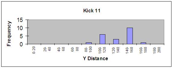
90 Figure D.3: Y histograms for the four analyzed kicks. 88


91 Figure D.4: Theta histograms for the four analyzed kicks. 89
CS295-1 Final Project : AIBO
 CS295-1 Final Project : AIBO Mert Akdere, Ethan F. Leland December 20, 2005 Abstract This document is the final report for our CS295-1 Sensor Data Management Course Final Project: Project AIBO. The main
Learning and Using Models of Kicking Motions for Legged Robots
 Learning and Using Models of Kicking Motions for Legged Robots Sonia Chernova and Manuela Veloso Computer Science Department Carnegie Mellon University Pittsburgh, PA 15213 {soniac, mmv}@cs.cmu.edu Abstract
S.P.Q.R. Legged Team Report from RoboCup 2003
 S.P.Q.R. Legged Team Report from RoboCup 2003 L. Iocchi and D. Nardi Dipartimento di Informatica e Sistemistica Universitá di Roma La Sapienza Via Salaria 113-00198 Roma, Italy {iocchi,nardi}@dis.uniroma1.it,
CORC 3303 Exploring Robotics. Why Teams?
 Exploring Robotics Lecture F Robot Teams Topics: 1) Teamwork and Its Challenges 2) Coordination, Communication and Control 3) RoboCup Why Teams? It takes two (or more) Such as cooperative transportation:
Learning and Using Models of Kicking Motions for Legged Robots
 Learning and Using Models of Kicking Motions for Legged Robots Sonia Chernova and Manuela Veloso Computer Science Department Carnegie Mellon University Pittsburgh, PA 15213 {soniac, mmv}@cs.cmu.edu Abstract
FU-Fighters. The Soccer Robots of Freie Universität Berlin. Why RoboCup? What is RoboCup?
 The Soccer Robots of Freie Universität Berlin We have been building autonomous mobile robots since 1998. Our team, composed of students and researchers from the Mathematics and Computer Science Department,
Find Kick Play An Innate Behavior for the Aibo Robot
 Find Kick Play An Innate Behavior for the Aibo Robot Ioana Butoi 05 Advisors: Prof. Douglas Blank and Prof. Geoffrey Towell Bryn Mawr College, Computer Science Department Senior Thesis Spring 2005 Abstract
CS 393R. Lab Introduction. Todd Hester
 CS 393R Lab Introduction Todd Hester todd@cs.utexas.edu Outline The Lab: ENS 19N Website Software: Tekkotsu Robots: Aibo ERS-7 M3 Assignment 1 Lab Rules My information Office hours Wednesday 11-noon ENS
Multi Robot Localization assisted by Teammate Robots and Dynamic Objects
 Multi Robot Localization assisted by Teammate Robots and Dynamic Objects Anil Kumar Katti Department of Computer Science University of Texas at Austin akatti@cs.utexas.edu ABSTRACT This paper discusses
An Open Robot Simulator Environment
 An Open Robot Simulator Environment Toshiyuki Ishimura, Takeshi Kato, Kentaro Oda, and Takeshi Ohashi Dept. of Artificial Intelligence, Kyushu Institute of Technology isshi@mickey.ai.kyutech.ac.jp Abstract.
Saphira Robot Control Architecture
 Saphira Robot Control Architecture Saphira Version 8.1.0 Kurt Konolige SRI International April, 2002 Copyright 2002 Kurt Konolige SRI International, Menlo Park, California 1 Saphira and Aria System Overview
Task Allocation: Role Assignment. Dr. Daisy Tang
 Task Allocation: Role Assignment Dr. Daisy Tang Outline Multi-robot dynamic role assignment Task Allocation Based On Roles Usually, a task is decomposed into roleseither by a general autonomous planner,
DC CIRCUITS AND OHM'S LAW
 July 15, 2008 DC Circuits and Ohm s Law 1 Name Date Partners DC CIRCUITS AND OHM'S LAW AMPS - VOLTS OBJECTIVES OVERVIEW To learn to apply the concept of potential difference (voltage) to explain the action
CMDragons 2009 Team Description
 CMDragons 2009 Team Description Stefan Zickler, Michael Licitra, Joydeep Biswas, and Manuela Veloso Carnegie Mellon University {szickler,mmv}@cs.cmu.edu {mlicitra,joydeep}@andrew.cmu.edu Abstract. In this
AGENT PLATFORM FOR ROBOT CONTROL IN REAL-TIME DYNAMIC ENVIRONMENTS. Nuno Sousa Eugénio Oliveira
 AGENT PLATFORM FOR ROBOT CONTROL IN REAL-TIME DYNAMIC ENVIRONMENTS Nuno Sousa Eugénio Oliveira Faculdade de Egenharia da Universidade do Porto, Portugal Abstract: This paper describes a platform that enables
CSCI 445 Laurent Itti. Group Robotics. Introduction to Robotics L. Itti & M. J. Mataric 1
 Introduction to Robotics CSCI 445 Laurent Itti Group Robotics Introduction to Robotics L. Itti & M. J. Mataric 1 Today s Lecture Outline Defining group behavior Why group behavior is useful Why group behavior
Studuino Icon Programming Environment Guide
 Studuino Icon Programming Environment Guide Ver 0.9.6 4/17/2014 This manual introduces the Studuino Software environment. As the Studuino programming environment develops, these instructions may be edited
Robotic Systems ECE 401RB Fall 2007
 The following notes are from: Robotic Systems ECE 401RB Fall 2007 Lecture 14: Cooperation among Multiple Robots Part 2 Chapter 12, George A. Bekey, Autonomous Robots: From Biological Inspiration to Implementation
Multi-Robot Coordination. Chapter 11
 Multi-Robot Coordination Chapter 11 Objectives To understand some of the problems being studied with multiple robots To understand the challenges involved with coordinating robots To investigate a simple
Multi-Platform Soccer Robot Development System
 Multi-Platform Soccer Robot Development System Hui Wang, Han Wang, Chunmiao Wang, William Y. C. Soh Division of Control & Instrumentation, School of EEE Nanyang Technological University Nanyang Avenue,
Multi-Robot Cooperative System For Object Detection
 Multi-Robot Cooperative System For Object Detection Duaa Abdel-Fattah Mehiar AL-Khawarizmi international collage Duaa.mehiar@kawarizmi.com Abstract- The present study proposes a multi-agent system based
Dipartimento di Elettronica Informazione e Bioingegneria Robotics
 Dipartimento di Elettronica Informazione e Bioingegneria Robotics Behavioral robotics @ 2014 Behaviorism behave is what organisms do Behaviorism is built on this assumption, and its goal is to promote
Multi Robot Systems: The EagleKnights/RoboBulls Small- Size League RoboCup Architecture
 Multi Robot Systems: The EagleKnights/RoboBulls Small- Size League RoboCup Architecture Alfredo Weitzenfeld University of South Florida Computer Science and Engineering Department Tampa, FL 33620-5399
The UNSW RoboCup 2000 Sony Legged League Team
 The UNSW RoboCup 2000 Sony Legged League Team Bernhard Hengst, Darren Ibbotson, Son Bao Pham, John Dalgliesh, Mike Lawther, Phil Preston, Claude Sammut School of Computer Science and Engineering University
Keywords: Multi-robot adversarial environments, real-time autonomous robots
 ROBOT SOCCER: A MULTI-ROBOT CHALLENGE EXTENDED ABSTRACT Manuela M. Veloso School of Computer Science Carnegie Mellon University Pittsburgh, PA 15213, USA veloso@cs.cmu.edu Abstract Robot soccer opened
Team KMUTT: Team Description Paper
 Team KMUTT: Team Description Paper Thavida Maneewarn, Xye, Pasan Kulvanit, Sathit Wanitchaikit, Panuvat Sinsaranon, Kawroong Saktaweekulkit, Nattapong Kaewlek Djitt Laowattana King Mongkut s University
Baset Adult-Size 2016 Team Description Paper
 Baset Adult-Size 2016 Team Description Paper Mojtaba Hosseini, Vahid Mohammadi, Farhad Jafari 2, Dr. Esfandiar Bamdad 1 1 Humanoid Robotic Laboratory, Robotic Center, Baset Pazhuh Tehran company. No383,
Nao Devils Dortmund. Team Description for RoboCup Matthias Hofmann, Ingmar Schwarz, and Oliver Urbann
 Nao Devils Dortmund Team Description for RoboCup 2014 Matthias Hofmann, Ingmar Schwarz, and Oliver Urbann Robotics Research Institute Section Information Technology TU Dortmund University 44221 Dortmund,
Preliminary Design Report. Project Title: Search and Destroy
 EEL 494 Electrical Engineering Design (Senior Design) Preliminary Design Report 9 April 0 Project Title: Search and Destroy Team Member: Name: Robert Bethea Email: bbethea88@ufl.edu Project Abstract Name:
Soccer Server: a simulator of RoboCup. NODA Itsuki. below. in the server, strategies of teams are compared mainly
 Soccer Server: a simulator of RoboCup NODA Itsuki Electrotechnical Laboratory 1-1-4 Umezono, Tsukuba, 305 Japan noda@etl.go.jp Abstract Soccer Server is a simulator of RoboCup. Soccer Server provides an
Robo Golf. Team 9 Juan Quiroz Vincent Ravera. CPE 470/670 Autonomous Mobile Robots. Friday, December 16, 2005
 Robo Golf Team 9 Juan Quiroz Vincent Ravera CPE 470/670 Autonomous Mobile Robots Friday, December 16, 2005 Team 9: Quiroz, Ravera 2 Table of Contents Introduction...3 Robot Design...3 Hardware...3 Software...
Keytar Hero. Bobby Barnett, Katy Kahla, James Kress, and Josh Tate. Teams 9 and 10 1
 Teams 9 and 10 1 Keytar Hero Bobby Barnett, Katy Kahla, James Kress, and Josh Tate Abstract This paper talks about the implementation of a Keytar game on a DE2 FPGA that was influenced by Guitar Hero.
Using Reactive and Adaptive Behaviors to Play Soccer
 AI Magazine Volume 21 Number 3 (2000) ( AAAI) Articles Using Reactive and Adaptive Behaviors to Play Soccer Vincent Hugel, Patrick Bonnin, and Pierre Blazevic This work deals with designing simple behaviors
MINHO ROBOTIC FOOTBALL TEAM. Carlos Machado, Sérgio Sampaio, Fernando Ribeiro
 MINHO ROBOTIC FOOTBALL TEAM Carlos Machado, Sérgio Sampaio, Fernando Ribeiro Grupo de Automação e Robótica, Department of Industrial Electronics, University of Minho, Campus de Azurém, 4800 Guimarães,
Versatile Camera Machine Vision Lab
 Versatile Camera Machine Vision Lab In-Sight Explorer 5.6.0-1 - Table of Contents Pill Inspection... Error! Bookmark not defined. Get Connected... Error! Bookmark not defined. Set Up Image... - 8 - Location
Communications for cooperation: the RoboCup 4-legged passing challenge
 Communications for cooperation: the RoboCup 4-legged passing challenge Carlos E. Agüero Durán, Vicente Matellán, José María Cañas, Francisco Martín Robotics Lab - GSyC DITTE - ESCET - URJC {caguero,vmo,jmplaza,fmartin}@gsyc.escet.urjc.es
Hanuman KMUTT: Team Description Paper
 Hanuman KMUTT: Team Description Paper Wisanu Jutharee, Sathit Wanitchaikit, Boonlert Maneechai, Natthapong Kaewlek, Thanniti Khunnithiwarawat, Pongsakorn Polchankajorn, Nakarin Suppakun, Narongsak Tirasuntarakul,
Major Project SSAD. Mentor : Raghudeep SSAD Mentor :Manish Jha Group : Group20 Members : Harshit Daga ( ) Aman Saxena ( )
 Aman Saxena ( )") Major Project SSAD Advisor : Dr. Kamalakar Karlapalem Mentor : Raghudeep SSAD Mentor :Manish Jha Group : Group20 Members : Harshit Daga (200801028) Aman Saxena (200801010) We were supposed to calculate
Major Project SSAD Advisor : Dr. Kamalakar Karlapalem Mentor : Raghudeep SSAD Mentor :Manish Jha Group : Group20 Members : Harshit Daga (200801028) Aman Saxena (200801010) We were supposed to calculate
RoboCup. Presented by Shane Murphy April 24, 2003
 RoboCup Presented by Shane Murphy April 24, 2003 RoboCup: : Today and Tomorrow What we have learned Authors Minoru Asada (Osaka University, Japan), Hiroaki Kitano (Sony CS Labs, Japan), Itsuki Noda (Electrotechnical(
Efficient UMTS. 1 Introduction. Lodewijk T. Smit and Gerard J.M. Smit CADTES, May 9, 2003
 Efficient UMTS Lodewijk T. Smit and Gerard J.M. Smit CADTES, email:smitl@cs.utwente.nl May 9, 2003 This article gives a helicopter view of some of the techniques used in UMTS on the physical and link layer.
Your EdVenture into Robotics 10 Lesson plans
 Your EdVenture into Robotics 10 Lesson plans Activity sheets and Worksheets Find Edison Robot @ Search: Edison Robot Call 800.962.4463 or email custserv@ Lesson 1 Worksheet 1.1 Meet Edison Edison is a
The description of team KIKS
 The description of team KIKS Keitaro YAMAUCHI 1, Takamichi YOSHIMOTO 2, Takashi HORII 3, Takeshi CHIKU 4, Masato WATANABE 5,Kazuaki ITOH 6 and Toko SUGIURA 7 Toyota National College of Technology Department
LPR Camera Installation and Configuration Manual
 LPR Camera Installation and Configuration Manual 1.Installation Instruction 1.1 Installation location The camera should be installed behind the barrier and facing the vehicle direction as illustrated in
Content. 3 Preface 4 Who We Are 6 The RoboCup Initiative 7 Our Robots 8 Hardware 10 Software 12 Public Appearances 14 Achievements 15 Interested?
 Content 3 Preface 4 Who We Are 6 The RoboCup Initiative 7 Our Robots 8 Hardware 10 Software 12 Public Appearances 14 Achievements 15 Interested? 2 Preface Dear reader, Robots are in everyone's minds nowadays.
CURIE Academy, Summer 2014 Lab 2: Computer Engineering Software Perspective Sign-Off Sheet
 Lab : Computer Engineering Software Perspective Sign-Off Sheet NAME: NAME: DATE: Sign-Off Milestone TA Initials Part 1.A Part 1.B Part.A Part.B Part.C Part 3.A Part 3.B Part 3.C Test Simple Addition Program
Cooperative Distributed Vision for Mobile Robots Emanuele Menegatti, Enrico Pagello y Intelligent Autonomous Systems Laboratory Department of Informat
 Cooperative Distributed Vision for Mobile Robots Emanuele Menegatti, Enrico Pagello y Intelligent Autonomous Systems Laboratory Department of Informatics and Electronics University ofpadua, Italy y also
KMUTT Kickers: Team Description Paper
 KMUTT Kickers: Team Description Paper Thavida Maneewarn, Xye, Korawit Kawinkhrue, Amnart Butsongka, Nattapong Kaewlek King Mongkut s University of Technology Thonburi, Institute of Field Robotics (FIBO)
Robocup Electrical Team 2006 Description Paper
 Robocup Electrical Team 2006 Description Paper Name: Strive2006 (Shanghai University, P.R.China) Address: Box.3#,No.149,Yanchang load,shanghai, 200072 Email: wanmic@163.com Homepage: robot.ccshu.org Abstract:
The UPennalizers RoboCup Standard Platform League Team Description Paper 2017
 The UPennalizers RoboCup Standard Platform League Team Description Paper 2017 Yongbo Qian, Xiang Deng, Alex Baucom and Daniel D. Lee GRASP Lab, University of Pennsylvania, Philadelphia PA 19104, USA, https://www.grasp.upenn.edu/
ZJUDancer Team Description Paper Humanoid Kid-Size League of Robocup 2015
 ZJUDancer Team Description Paper Humanoid Kid-Size League of Robocup 2015 Yu DongDong, Liu Yun, Zhou Chunlin, and Xiong Rong State Key Lab. of Industrial Control Technology, Zhejiang University, Hangzhou,
One connected to the trainer port, MagTrack should be configured, please see Configuration section on this manual.
 MagTrack R Head Tracking System Instruction Manual ABSTRACT MagTrack R is a magnetic Head Track system intended to be used for FPV flight. The system measures the components of the magnetic earth field
Robo-Erectus Jr-2013 KidSize Team Description Paper.
 Robo-Erectus Jr-2013 KidSize Team Description Paper. Buck Sin Ng, Carlos A. Acosta Calderon and Changjiu Zhou. Advanced Robotics and Intelligent Control Centre, Singapore Polytechnic, 500 Dover Road, 139651,
Brainstorm. In addition to cameras / Kinect, what other kinds of sensors would be useful?
 Brainstorm In addition to cameras / Kinect, what other kinds of sensors would be useful? How do you evaluate different sensors? Classification of Sensors Proprioceptive sensors measure values internally
15 TUBE CLEANER: A SIMPLE SHOOTING GAME
 15 TUBE CLEANER: A SIMPLE SHOOTING GAME Tube Cleaner was designed by Freid Lachnowicz. It is a simple shooter game that takes place in a tube. There are three kinds of enemies, and your goal is to collect
Robots in the Loop: Supporting an Incremental Simulation-based Design Process
 s in the Loop: Supporting an Incremental -based Design Process Xiaolin Hu Computer Science Department Georgia State University Atlanta, GA, USA xhu@cs.gsu.edu Abstract This paper presents the results of
LEGO MINDSTORMS CHEERLEADING ROBOTS
 LEGO MINDSTORMS CHEERLEADING ROBOTS Naohiro Matsunami\ Kumiko Tanaka-Ishii 2, Ian Frank 3, and Hitoshi Matsubara3 1 Chiba University, Japan 2 Tokyo University, Japan 3 Future University-Hakodate, Japan
Confidence-Based Multi-Robot Learning from Demonstration
 Int J Soc Robot (2010) 2: 195 215 DOI 10.1007/s12369-010-0060-0 Confidence-Based Multi-Robot Learning from Demonstration Sonia Chernova Manuela Veloso Accepted: 5 May 2010 / Published online: 19 May 2010
Test Plan. Robot Soccer. ECEn Senior Project. Real Madrid. Daniel Gardner Warren Kemmerer Brandon Williams TJ Schramm Steven Deshazer
 Test Plan Robot Soccer ECEn 490 - Senior Project Real Madrid Daniel Gardner Warren Kemmerer Brandon Williams TJ Schramm Steven Deshazer CONTENTS Introduction... 3 Skill Tests Determining Robot Position...
MULTI-LAYERED HYBRID ARCHITECTURE TO SOLVE COMPLEX TASKS OF AN AUTONOMOUS MOBILE ROBOT
 MULTI-LAYERED HYBRID ARCHITECTURE TO SOLVE COMPLEX TASKS OF AN AUTONOMOUS MOBILE ROBOT F. TIECHE, C. FACCHINETTI and H. HUGLI Institute of Microtechnology, University of Neuchâtel, Rue de Tivoli 28, CH-2003
SRV02-Series Rotary Experiment # 3. Ball & Beam. Student Handout
 SRV02-Series Rotary Experiment # 3 Ball & Beam Student Handout SRV02-Series Rotary Experiment # 3 Ball & Beam Student Handout 1. Objectives The objective in this experiment is to design a controller for
due Thursday 10/14 at 11pm (Part 1 appears in a separate document. Both parts have the same submission deadline.)
") CS2 Fall 200 Project 3 Part 2 due Thursday 0/4 at pm (Part appears in a separate document. Both parts have the same submission deadline.) You must work either on your own or with one partner. You may discuss
CS2 Fall 200 Project 3 Part 2 due Thursday 0/4 at pm (Part appears in a separate document. Both parts have the same submission deadline.) You must work either on your own or with one partner. You may discuss
Lab 3 DC CIRCUITS AND OHM'S LAW
 43 Name Date Partners Lab 3 DC CIRCUITS AND OHM'S LAW AMPS + - VOLTS OBJECTIVES To learn to apply the concept of potential difference (voltage) to explain the action of a battery in a circuit. To understand
ZJUDancer Team Description Paper Humanoid Kid-Size League of Robocup 2014
 ZJUDancer Team Description Paper Humanoid Kid-Size League of Robocup 2014 Yu DongDong, Xiang Chuan, Zhou Chunlin, and Xiong Rong State Key Lab. of Industrial Control Technology, Zhejiang University, Hangzhou,
Validation Document. ELEC 491 Capstone Proposal - Dynamic Projector Mount Project. Andy Kwan Smaran Karimbil Siamak Rahmanian Dante Ye
 Validation Document ELEC 491 Capstone Proposal - Dynamic Projector Mount Project Andy Kwan Smaran Karimbil Siamak Rahmanian Dante Ye Executive Summary: The purpose of this document is to describe the tests
Robotics using Lego Mindstorms EV3 (Intermediate)
") Robotics using Lego Mindstorms EV3 (Intermediate) Facebook.com/roboticsgateway @roboticsgateway Robotics using EV3 Are we ready to go Roboticists? Does each group have at least one laptop? Do you have
Robotics using Lego Mindstorms EV3 (Intermediate) Facebook.com/roboticsgateway @roboticsgateway Robotics using EV3 Are we ready to go Roboticists? Does each group have at least one laptop? Do you have
GlassSpection User Guide
 i GlassSpection User Guide GlassSpection User Guide v1.1a January2011 ii Support: Support for GlassSpection is available from Pyramid Imaging. Send any questions or test images you want us to evaluate
Outline / Wireless Networks and Applications Lecture 2: Networking Overview and Wireless Challenges. Protocol and Service Levels
 18-452/18-750 Wireless s and s Lecture 2: ing Overview and Wireless Challenges Peter Steenkiste Carnegie Mellon University Spring Semester 2017 http://www.cs.cmu.edu/~prs/wirelesss17/ Peter A. Steenkiste,
2 Our Hardware Architecture
 RoboCup-99 Team Descriptions Middle Robots League, Team NAIST, pages 170 174 http: /www.ep.liu.se/ea/cis/1999/006/27/ 170 Team Description of the RoboCup-NAIST NAIST Takayuki Nakamura, Kazunori Terada,
Range Sensing strategies
 Range Sensing strategies Active range sensors Ultrasound Laser range sensor Slides adopted from Siegwart and Nourbakhsh 4.1.6 Range Sensors (time of flight) (1) Large range distance measurement -> called
The Sony AIBO: Using IR for Maze Navigation
 The Sony AIBO: Using IR for Maze Navigation Kyle Lawton and Elizabeth Shrecengost Abstract The goal of this project was to design a behavior that allows the Sony AIBO to navigate and explore a maze. This
Tutorial: Creating maze games
 Tutorial: Creating maze games Copyright 2003, Mark Overmars Last changed: March 22, 2003 (finished) Uses: version 5.0, advanced mode Level: Beginner Even though Game Maker is really simple to use and creating
Multi-Agent Programming Contest Scenario Description 2009 Edition
 Multi-Agent Programming Contest Scenario Description 2009 Edition Revised 18.06.2009 http://www.multiagentcontest.org/2009 Tristan Behrens Mehdi Dastani Jürgen Dix Michael Köster Peter Novák An unknown
Programming with network Sockets Computer Science Department, University of Crete. Manolis Surligas October 16, 2017
 Programming with network Sockets Computer Science Department, University of Crete Manolis Surligas surligas@csd.uoc.gr October 16, 2017 Manolis Surligas (CSD, UoC) Programming with network Sockets October
LAB 1 Linear Motion and Freefall
 Cabrillo College Physics 10L Name LAB 1 Linear Motion and Freefall Read Hewitt Chapter 3 What to learn and explore A bat can fly around in the dark without bumping into things by sensing the echoes of
The key to a fisheye is the relationship between latitude ø of the 3D vector and radius on the 2D fisheye image, namely a linear one where
 Fisheye mathematics Fisheye image y 3D world y 1 r P θ θ -1 1 x ø x (x,y,z) -1 z Any point P in a linear (mathematical) fisheye defines an angle of longitude and latitude and therefore a 3D vector into
Lab 4 Projectile Motion
 b Lab 4 Projectile Motion What You Need To Know: x x v v v o ox ox v v ox at 1 t at a x FIGURE 1 Linear Motion Equations The Physics So far in lab you ve dealt with an object moving horizontally or an
This study provides models for various components of study: (1) mobile robots with on-board sensors (2) communication, (3) the S-Net (includes computa
 mobile robots with on-board sensors (2) communication, (3) the S-Net (includes computa") S-NETS: Smart Sensor Networks Yu Chen University of Utah Salt Lake City, UT 84112 USA yuchen@cs.utah.edu Thomas C. Henderson University of Utah Salt Lake City, UT 84112 USA tch@cs.utah.edu Abstract: The
S-NETS: Smart Sensor Networks Yu Chen University of Utah Salt Lake City, UT 84112 USA yuchen@cs.utah.edu Thomas C. Henderson University of Utah Salt Lake City, UT 84112 USA tch@cs.utah.edu Abstract: The
Week 2 Lecture 1. Introduction to Communication Networks. Review: Analog and digital communications
 Week 2 Lecture 1 Introduction to Communication Networks Review: Analog and digital communications Topic: Internet Trend, Protocol, Transmission Principle Digital Communications is the foundation of Internet
Multi-Humanoid World Modeling in Standard Platform Robot Soccer
 Multi-Humanoid World Modeling in Standard Platform Robot Soccer Brian Coltin, Somchaya Liemhetcharat, Çetin Meriçli, Junyun Tay, and Manuela Veloso Abstract In the RoboCup Standard Platform League (SPL),
Robo-Erectus Tr-2010 TeenSize Team Description Paper.
 Robo-Erectus Tr-2010 TeenSize Team Description Paper. Buck Sin Ng, Carlos A. Acosta Calderon, Nguyen The Loan, Guohua Yu, Chin Hock Tey, Pik Kong Yue and Changjiu Zhou. Advanced Robotics and Intelligent
A Performance Comparison of Multi-Hop Wireless Ad Hoc Network Routing Protocols
 A Performance Comparison of Multi-Hop Wireless Ad Hoc Network Routing Protocols Josh Broch, David Maltz, David Johnson, Yih-Chun Hu and Jorjeta Jetcheva Computer Science Department Carnegie Mellon University
Virtual Mix Room. User Guide
 Virtual Mix Room User Guide TABLE OF CONTENTS Chapter 1 Introduction... 3 1.1 Welcome... 3 1.2 Product Overview... 3 1.3 Components... 4 Chapter 2 Quick Start Guide... 5 Chapter 3 Interface and Controls...
MAKER: Development of Smart Mobile Robot System to Help Middle School Students Learn about Robot Perception
 Paper ID #14537 MAKER: Development of Smart Mobile Robot System to Help Middle School Students Learn about Robot Perception Dr. Sheng-Jen Tony Hsieh, Texas A&M University Dr. Sheng-Jen ( Tony ) Hsieh is
Vision Ques t. Vision Quest. Use the Vision Sensor to drive your robot in Vision Quest!
 Vision Ques t Vision Quest Use the Vision Sensor to drive your robot in Vision Quest! Seek Discover new hands-on builds and programming opportunities to further your understanding of a subject matter.
CAD Orientation (Mechanical and Architectural CAD)
") Design and Drafting Description This is an introductory computer aided design (CAD) activity designed to give students the foundational skills required to complete future lessons. Students will learn all
Design and Drafting Description This is an introductory computer aided design (CAD) activity designed to give students the foundational skills required to complete future lessons. Students will learn all
1.3. Before loading the holder into the TEM, make sure the X tilt is set to zero and the goniometer locked in place (this will make loading easier).
.") JEOL 200CX operating procedure Nicholas G. Rudawski ngr@ufl.edu (805) 252-4916 1. Specimen loading 1.1. Unlock the TUMI system. 1.2. Load specimen(s) into the holder. If using the double tilt holder, ensure
JEOL 200CX operating procedure Nicholas G. Rudawski ngr@ufl.edu (805) 252-4916 1. Specimen loading 1.1. Unlock the TUMI system. 1.2. Load specimen(s) into the holder. If using the double tilt holder, ensure
1 Best Practices Course Week 12 Part 2 copyright 2012 by Eric Bobrow. BEST PRACTICES COURSE WEEK 12 PART 2 Program Planning Areas and Lists of Spaces
 BEST PRACTICES COURSE WEEK 12 PART 2 Program Planning Areas and Lists of Spaces Hello, this is Eric Bobrow. And in this lesson, we'll take a look at how you can create a site survey drawing in ArchiCAD
In this project you ll learn how to create a platform game, in which you have to dodge the moving balls and reach the end of the level.
 Dodgeball Introduction In this project you ll learn how to create a platform game, in which you have to dodge the moving balls and reach the end of the level. Step 1: Character movement Let s start by
Hierarchical Controller for Robotic Soccer
 Hierarchical Controller for Robotic Soccer Byron Knoll Cognitive Systems 402 April 13, 2008 ABSTRACT RoboCup is an initiative aimed at advancing Artificial Intelligence (AI) and robotics research. This
ivu Plus Quick Start Guide P/N rev. A -- 10/8/2010
 P/N 154721 rev. A -- 10/8/2010 Contents Contents 1 Introduction...3 2 ivu Plus Major Features...4 2.1 Demo Mode...4 2.2 Sensor Types...4 2.2.1 Selecting a Sensor Type...5 2.3 Multiple Inspections...6 2.3.1
Formation and Cooperation for SWARMed Intelligent Robots
 Formation and Cooperation for SWARMed Intelligent Robots Wei Cao 1 Yanqing Gao 2 Jason Robert Mace 3 (West Virginia University 1 University of Arizona 2 Energy Corp. of America 3 ) Abstract This article
Perception. Read: AIMA Chapter 24 & Chapter HW#8 due today. Vision
 11-25-2013 Perception Vision Read: AIMA Chapter 24 & Chapter 25.3 HW#8 due today visual aural haptic & tactile vestibular (balance: equilibrium, acceleration, and orientation wrt gravity) olfactory taste
DISCO DICING SAW SOP. April 2014 INTRODUCTION
 DISCO DICING SAW SOP April 2014 INTRODUCTION The DISCO Dicing saw is an essential piece of equipment that allows cleanroom users to divide up their processed wafers into individual chips. The dicing saw
Real Time Word to Picture Translation for Chinese Restaurant Menus
 Real Time Word to Picture Translation for Chinese Restaurant Menus Michelle Jin, Ling Xiao Wang, Boyang Zhang Email: mzjin12, lx2wang, boyangz @stanford.edu EE268 Project Report, Spring 2014 Abstract--We
EE 314 Spring 2003 Microprocessor Systems
 EE 314 Spring 2003 Microprocessor Systems Laboratory Project #9 Closed Loop Control Overview and Introduction This project will bring together several pieces of software and draw on knowledge gained in
Lab 4 OHM S LAW AND KIRCHHOFF S CIRCUIT RULES
 57 Name Date Partners Lab 4 OHM S LAW AND KIRCHHOFF S CIRCUIT RULES AMPS - VOLTS OBJECTIVES To learn to apply the concept of potential difference (voltage) to explain the action of a battery in a circuit.
Nova Full-Screen Calibration System
 Nova Full-Screen Calibration System Version: 5.0 1 Preparation Before the Calibration 1 Preparation Before the Calibration 1.1 Description of Operating Environments Full-screen calibration, which is used
Lab 7: Introduction to Webots and Sensor Modeling
 Lab 7: Introduction to Webots and Sensor Modeling This laboratory requires the following software: Webots simulator C development tools (gcc, make, etc.) The laboratory duration is approximately two hours.
Speed of Sound in Air
 Speed of Sound in Air OBJECTIVE To explain the condition(s) necessary to achieve resonance in an open tube. To understand how the velocity of sound is affected by air temperature. To determine the speed
White Paper High Dynamic Range Imaging
 WPE-2015XI30-00 for Machine Vision What is Dynamic Range? Dynamic Range is the term used to describe the difference between the brightest part of a scene and the darkest part of a scene at a given moment