GPS Error and Biases
|
|
|
- Emma McCarthy
- 5 years ago
- Views:
Transcription
1 Component-I(A) - Personal Details Role Name Affiliation Principal Investigator Prof.MasoodAhsanSiddiqui Department of Geography, JamiaMilliaIslamia, New Delhi Paper Coordinator, if any Dr. Mahaveer Punia BISR, Jaipur Content Writer/Author (CW) Prof.MasoodAhsanSiddiqui Department of Geography, JamiaMilliaIslamia, New Delhi Content Reviewer (CR) Dr. Mahaveer Punia BISR, Jaipur Language Editor (LE) Component-I (B) - Description of Module Items Subject Name Paper Name Module Name/Title Description of Module Geography Remote Sensing, GIS, GPS GPS Error and Biases Module Id RS/GIS-34 Pre-requisites Objectives Keywords
2 GPS Error and Biases Outline GPS error and Bias introduction GPS Ephemeris Errors Selective availability Satellite and Receiver Clock Errors Multipath Error Antenna phase center variation Receiver measurement noise Ionospheric delay Tropospheric delay Satellite geometry measures User equivalent range error
3 Introduction GPS pseudo range and carrier phase measurements are both affected by several types of random errors and biases (systematic errors). These errors may be classified as those originating at the satellites, those originating at the receiver, and those that are due to signal propagation (atmospheric refraction). Figure 1 shows the various errors and biases. The errors originating at the satellites include ephemeris, or orbital errors, satellite clock errors, and the effect of selective availability. The later was intentionally implemented by the U.S. department of defense to degrade the autonomous GPS accuracy for security reasons. It was, however, terminated at midnight (eastern daylight time) on May 1, The errors originating at the receiver include receiver clock errors, multipath error, receiver noise, and antenna phase center variations. The signal propagation errors include the delay of the GPS signal as it passes through the ionospheric and tropospheric layers of the atmosphere. In fact, it is only in a vacuum (free space) that the GPS signal travels, or propagates, at the speed of light. In addition to the effect of these errors, the accuracy of the computed GPS position is also affected by the geometric locations of the GPS satellites as seen by the receiver. The more spread out the satellites are in the sky, the better the obtained accuracy.

4 Fig.1: GPS Error GPS Ephemeris Errors Satellite positions as a function of time, which are included in the broadcast satellite navigation message, are predicted from previous GPS observations at the ground control stations. Typically, overlapping 4-hour GPS data spans are used by the operational control system to predict fresh satellite orbital elements for each 1-hour period. As might be expected, modeling the forces acting on the GPS satellites will not be perfect, which causes some errors in the estimated satellite positions, known as ephemeris errors. Nominally, an ephemeris error is usually in the order of 2m to 5m, and can reach up to 50 m under selective availability. According to, the range error due to the combined effect of the ephemeris and the Satellite clock errors is of the order of 2.3m. An ephemeris error for a particular satellite is identical to all GPS users worldwide. However, as different users see the same satellite at different view angles, the effect of the ephemeris error on the range measurement, and consequently on the computed position, is different. This means that combining (differencing) the measurements of two receivers simultaneously
5 tracking a particular satellite cannot totally remove the ephemeris error. Users of short separations, however, will have an almost identical range error due to the ephemeris error, which can essentially be removed through differencing the observations. For relative positioning, the following rule of thumb gives a rough estimate of the effect of the ephemeris error on the baseline solution. Some applications, such as studies of the crustal dynamics of the earth, require more precise ephemeris data than the broadcast ephemeris. To support these applications, several institutions [e.g., the International GPS Service for Geodynamics (IGS), the U.S. National Geodetic Survey (NGS), and Geomatics Canada have developed post mission precise orbital service. Precise ephemeris data is based on GPS data collected at a global GPS network coordinated by the IGS. At the present time, precise ephemeris data is available to users with some delay, which varies from 12 hours for the IGS ultra rapid orbit to about 12 days for the most precise IGS precise orbit. The corresponding accuracies for the two precise orbits are in the order of a few decimeters to 1 decimeter, respectively. Users can down load the precise ephemeris data free of charge from the IGS center Selective Availability GPS was originally designed so that real-time autonomous positioning and navigation with the civilian C/A code receivers would be less precise than military P-code receivers. Surprisingly, the obtained accuracy was almost the same from both receivers. To ensure national security, the U.S. department of defense implemented the so called selective availability (SA) on Block II GPS satellites to deny accurate real time autonomous positioning to unauthorized users. SA was officially activated on March SA introduces two types of errors. The first one, called delta error, results from dithering the satellite clock, and is common to all users worldwide.

6 The second one, called epsilon error, is an additional slowly varying orbital error. With SA turned on, nominal horizontal and vertical errors can be up to 100m and 156 m, respectively, at the 95% probability level. Figure 2 shows how the horizontal position of a stationary GPS receiver varies over time, mainly as a result of the effect of SA. Like the range error due to ephemeris error, the range error due to epsilon error is almost identical between users of short separations. Therefore, using differential GPS (DGPS; see Chapter S) would overcome the effect of the epsilon error. In fact, DGPS provides better accuracy than the standalone P-code receiver due to the elimination or the reduction of the common errors, including SA. Following extensive studies, the U.S. government discontinued SA on May 1, 2000, resulting in a much improved autonomous GPS accuracy. With the SA turned off, the nominal autonomous GPS horizontal and vertical accuracies would be in the order of 22m and 33m. Fig.2: GPS accuracy error before and after deactivation of selective availability Source: Satellite and Receiver Clock Errors The clocks in the satellite are very accurate (to about 3 nanoseconds),
7 they do sometimes drift slightly and cause small errors, affecting the accuracy of the position. The US department of defense monitors the satellite clocks using the Control Segment and can correct any drift that is found. Each GPS Block II and Block IIA satellite contains four atomic clocks, two cesium and two rubidium. The newer generation Block IIR satellites carry rubidium clocks only. One of the onboard clocks, primarily a cesium for Block II and IIA, is selected to provide the frequency and the timing requirements for generating the GPS signals. The others are backups. The GPS satellite clocks, although highly accurate, are not perfect. Their stability is about 1 to 2 parts in 1013 over a period of one day. This means that the satellite clock error is about 8.64 to ns per day. The corresponding range error is 2.59m to 5.18m, which can be easily calculated by multiplying the clock error by the speed of light. Cesium clocks tend to behave better over a longer period of time compared with rubidium clocks. In fact, the stability of the cesium clocks over a period of 10 days or more improves to several parts in The performance of the satellite clocks is monitored by the ground control system. The amount of drift is calculated and transmitted as a part of the navigation message in the form of three coefficients of a second-degree polynomial. Satellite clock errors cause additional errors to the GPS measurements. These errors are common to all users observing the same satellite and can be removed through differencing between the receivers. Applying the satellite clock correction in the navigation message can also correct the satellite clock errors. This, however, leaves an error of the order of several nanoseconds, which translates to a range error of a few meters (one nanosecond error is equivalent to a range error of about 30 cm).gps receivers, in contrast, use inexpensive crystal clocks, which are much less accurate than the satellite clocks. As such, the


8 receiver clock error is much larger than that of the GPS satellite clock. It can, however, be removed through differencing between the satellites or it can be treated as an additional unknown parameter in the estimation process. Precise external clocks (usually cesium or rubidium) are used in some applications instead of the internal receiver clock. Although the external atomic clocks have superior performance compared with the internal receiver clocks, they cost between a few thousand dollars for the rubidium clocks to about $ 20,000 for the cesium clocks. Fig.3: Clock Error in GPS Source: Multipath Error
9 Multipath error is one of the predominant error sources in all GPS applications. Particularly the multipath error has to be precisely estimated in the Global Navigation Satellite Systems (GNSSs) as it is the major error source (2-4 m) that limits the GPS receiver s performance. Whenever, a signal is transmitted from a GPS satellite it follows a multiple number of propagation paths on its way to receiving antenna. These multiple signal paths are due to the fact that the signal gets reflected back to the antenna off surrounding objects, including the earth s surface. The GPS receiver tracks both the direct and reflected signal components. The radio wave transmitted from a satellite radiates in all directions, these radio waves including reflected waves that are reflected off due to various obstacles, diffracted waves, scattering waves, and the direct wave from the satellite to GPS receiver (fig.4) In this case, since the path lengths of the direct, reflected, diffracted, and scattering waves are different, the time each takes to reach the GPS receiver will be different. In addition the phase of the incoming wave varies because of reflections. As a result, the receiver receives a superposition consisting of several waves having different phase and times of arrival. The generic name of a radio wave in which the time of arrival is retarded in comparison with this direct wave is called a delayed wave. Then, the reception environment characterized by a superposition of delayed waves is called a multipath propagation environment. In a multipath propagation environment, the received signal is sometimes intensified. This phenomenon is called multipath fading and the signal level of the received wave changes from moment to moment. Multipath is a major error source for both the carrier-phase and pseudo range measurements. It occurs when the GPS signal arrives at the receiver antenna through different paths. These paths can be the direct line of sight signal and reflected signals from objects surrounding the receiver antenna. Multipath distorts the original signal through interference with the reflected signals at
10 the GPS antenna. It affects both the carrier-phase and pseudo range measurements; however, its size is much larger in the pseudo range measurements. The size of the carrier-phase multipath can reach a maximum value of a quarter of a cycle (about 4.8 cm for the L1 carrier phase). The pseudo range multipath can theoretically reach several tens of meters for the C/A-code measurements. However, with new advances in receiver technology, actual pseudo range multipath is reduced dramatically. Examples of such technologies are the Strobe correlated (Ashtech, Inc.) and the MEDLL (NovAtel, Inc.). With these multipath mitigation techniques, the pseudo range multipath error is reduced to several meters, even in a highly reflective environment. Under the same environment, the presence of multipath errors can be verified using a day-to-day correlation of the estimated residuals. This is because the satellite-reflector-antenna geometry repeats every sidereal day. However, multipath errors in the undifferenced pseudo range measurements can be identified if dual-frequency observations are available. A good general multipath model is still not available, mainly because of the variant satellite reflector antenna geometry. There are, however several options to reduce the effect of multipath. The option is to select an observation site with no reflecting objects in the vicinity of the receiver antenna. Another option to reduce the effect of multipath is to use a chock ring antenna (a chock ring device is a ground plane that has several concentric metal hoops, which attenuate the reflected signals). As the GPS signal is right handed circularly polarized while the reflected signal is left handed, reducing the effect of multipath may also be achieved by using an antenna with a matching polarization to the GPS. The disadvantage of this option, however, is that the polarization of the multipath signal becomes right handed again if it twice reflected.

11 Fig.4.Multipath Error Source: Antenna phase center variation A GPS antenna receives the incoming satellite signal and then converts its energy into an electric current, which can be handled by the GPS receiver. The point at which the GPS signal is received is called the antenna phase center. Generally, the antenna phase center does not coincide with the physical (geometrical) center of the antenna. It varies depending on the elevation and the azimuth of the GPS satellite as well as the intensity of the observed signal. As a result, additional range error can be expected. The size of the error caused by the antenna phase center variation depends on the antenna type, and is typically in the order of a few centimeters. It is, however, difficult to model the antenna phase center variation and, therefore, care has to be taken when selecting the antenna type. For short baselines with the same types of antennas at each end, the phase center error can be canceled if the antennas are oriented in the same direction. Mixing different types of antennas or using different orientations will not cancel the error. Due to its small size, this error is neglected in most of the
12 practical GPS applications. It should be pointed out that phase center errors could be different on L1 and L2 carrier phase observations. This can affect the accuracy of the ionosphere free linear combination, particularly when observing short baselines. As mentioned before, for short baselines, the errors are highly correlated over distance and cancel sufficiently through differencing. Therefore, using a single frequency might be more appropriate for short baselines in the static mode. Receiver measurement noise The receiver measurement noise results from the limitations of the receiver's electronics system. A good GPS system should have a minimum noise level. Generally, a GPS receiver performs a self test when the user turns it on. However, for high-cost precise GPS systems, it might be important for the user to perform the system evaluation. Two tests can be performed for evaluating a GPS receiver (system) a. zero baseline and b. short baseline tests. A zero baseline test is used to evaluate the receiver performance. The test involves using one antenna/preamplifier followed by a signal splitter that feeds two or more GPS receivers (see Figure.5). Several receiver problems such as inter channel biases and cycle slips can be detected with this test. As one antenna is used, the baseline solution should be zero. In other words, any nonzero value is attributed to the receiver noise. Although the zero baseline test provides useful information on the receiver performance, it does not provide any information on the antenna/preamplifier noise. The contribution of the receiver measurement noise to the range error will depend very much on the quality of the GPS receiver. Typical average value for range error due to the receiver measurement noise is of the order of 0.6m. To evaluate the actual field performance of a GPS system, it is necessary to include the antenna/preamplifier noise component. This
13 can be done using short baselines of a few meters apart, observed on two consecutive days (see Figure.5). In this case, the double difference residuals of one day would contain the system noise and the multipath effect. All other errors would cancel sufficiently. As the multipath signature repeats every sidereal day, differencing the double difference residuals between the two consecutive days eliminates the effect of multipath and leaves only the system noise. Fig.5: Zero baseline test for evaluating the performance of a GPS receiver Source: Ionospheric delay At the uppermost part of the earth's atmosphere, ultraviolet and X-ray radiations coming from the sun interact with the gas molecules and atoms. These interactions result in gas ionization: a large number of free "negatively charged" electrons and "positively charged" atoms and molecules. Such a region of the atmosphere where gas ionization takes place is called the ionosphere. It extends from an altitude of
14 approximately S0 km to about 1,000 km or even more (see Figure.6). In fact, the upper limit of the ionospheric region is not clearly defined. The electron density within the ionospheric region is not constant; it changes with altitude. As such, the ionospheric region is divided into sub regions, or layers, according to the electron density. These layers are named D (S0-90 km), E ( km), F1 ( km), and F2 (210-1,000 km), respectively, with F2 usually being the layer of maximum electron density. The altitude and thickness of those layers vary with time, as a result of the changes in the sun's radiation and the Earth's magnetic field. For example, the F1 layer disappears during the night and is more pronounced in the summer than in the winter. The question that may arise is: How would the ionosphere affect the GPS measurements? The ionosphere is a dispersive medium, which means it bends the GPS radio signal and changes its speed as it passes through the various ionospheric layers to reach a GPS receiver. Bending the GPS signal path causes a negligible range error, particularly if the satellite elevation angle is greater than 5. It is the change in the propagation speed that causes a significant range error, and therefore should be accounted for. The ionosphere speeds up the propagation of the carrier phase beyond the speed of light, while it slows down the PRN code (and the navigation message) by the same amount. That is, the receiver-satellite distance will be too short if measured by the carrier phase and too long if measured by the code, compaired with the actual distance. The ionospheric delay is proportional to the number of free electrons along the GPS signal path, called the total electron content (TEC). TEC, however, depends on a number of factors: (1) the time of day (electron density level reaches a daily maximum in early afternoon and a minimum around midnight at local time); (2) the time of year (electron density levels
15 are higher in winter than in summer);(3) the 11-year solar cycle (electron density levels reach a maximum value approximately every 11 years, which corresponds to a peak in the solar flare activities known as the solar cycle peak-in 2001we are currently around the peak of solar cycle number 23), and (4) the geographic location (electron density levels are minimum in mid latitude regions and highly irregular in polar and equatorial regions). As the ionosphere is a dispersive medium, it causes a delay that is frequency dependent. The lower the frequency, the greater the delay; that is, the L2 ionospheric delay is greater than that of L1. Generally, ionospheric delay is of the order of 5m to 1Sm, but can reach over 150m under extreme solar activities, at midday, and near the horizon. This discussion shows that the electron density level in the ionosphere varies with time and location. It is, however, highly correlated over relatively short distances, and therefore differencing the GPS observations between users of short separation can remove the major part of the ionospheric delay. Taking advantage of the ionosphere's dispersive nature, the ionospheric delay can be determined with a high degree of accuracy by combining the P-code pseudo range measurements on both L1 and L2. Unfortunately, however, the P-code is accessible by authorized users only. With the addition of a second C/A-code on L2 as part of the modernization program, this limitation will be removed. The L1 and L2 carrier-phase measurements may be combined in a similar fashion to determine the variation in the ionospheric delay, not the absolute value. Users with dual- frequency receivers can combine the L1 and L2 carrier phase measurements to generate the ionosphere-free linear combination to remove the ionospheric delay. The disadvantages of the ionosphere-free linear combination, however, are: (1) it has a relatively higher observation
16 noise, and (2) it does not preserve the integer nature of the ambiguity parameters. As such, the ionosphere-free linear combination is not recommended for short baselines. Single-frequency users cannot take advantage of the dispersive nature of the ionosphere. They can, however, use one of the empirical ionospheric models to correct up to 60% of the delay. The most widely used model is the Klobuchar model, whose coefficients are trans- mitted as part of the navigation message. Another solution for users with single-frequency GPS receivers is to use corrections from regional networks. Such corrections can be received in real time through communication links. Figure.6: Short baseline test for evaluating the performance of a GPS system Source: Tropospheric delay The troposphere is the electrically neutral atmospheric region that extends up to about 50 km from the surface of the earth. The troposphere is a nondispersive medium for radio frequencies below 1S GHz. As a result, it delays the GPS carriers and codes identically.
17 That is, the measured satellite to receiver range will be longer than the actual geometric range, which means that a distance between two receivers will be longer than the actual distance. Unlike the ionospheric delay, the tropospheric delay cannot be removed by combining the L1 and the L2 observations. This is mainly because the tropospheric delay is frequency independent. The tropospheric delay depends on the temperature, pressure, and humidity along the signal path through the troposphere. Signals from satellites at low elevation angles travel a longer path through the troposphere than those at higher elevation angles. Therefore, the tropospheric delay is minimized at the user's zenith and maximized near the horizon. Tropospheric delay results in values of about 2.3m at zenith (satellite directly overhead), about 9.3m for a 15 elevation angle, and about 20-28m for a 5 elevation angle. Tropospheric delay may be broken into two components, dry and wet. The dry component represents about 90% of the delay and can be predicted to a high degree of accuracy using mathematical models. The wet component of the tropospheric delay depends on the water vapor along the GPS signal path. Unlike the dry component, the wet component is not easy to predict. Several mathematical models use surface meteorological measurements (atmospheric pressure, temperature, and partial water vapor pressure) to compute the wet component. Unfortunately, however, the wet component is weakly correlated with surface meteorological data, which limits its prediction accuracy. It was found that using default meteorological data (1,010 mb for atmospheric pressure, 20 C for temperature, and 50% for relative humidity) gives satisfactory results in most cases.
18 Satellite geometry measures The various types of errors and biases discussed earlier directly affect the accuracy of the computed GPS position. Proper modeling of those errors and biases and/or appropriate combinations of the GPS observables will improve the positioning accuracy. However, these are not the only factors that affect the resulting GPS accuracy. The satellite geometry, which represents the geometric locations of the GPS satellites as seen by the receiver, plays a very important role in the total positioning accuracy. The better the satellite geometry strength, the better the obtained positioning accuracy. As such, the overall positioning accuracy of GPS is measured by the combined effect of the unmodeled measurement errors and the effect of the satellite geometry. Good satellite geometry is obtained when the satellites are spread out in the sky. In general, the more spread out the satellites are in the sky, the better the satellite geometry, and vice versa. Figure shows a simple graphical explanation of the satellite geometry effect using two satellites assuming a two-dimensional (2-D) case. In such a case, the receiver will be located at the intersection of two arcs of circles; each has a radius equal to the receiver-satellite distance and a center at the satellite itself. Because of the measurement errors, the measured receiver-satellite distance will not be exact and an uncertainty region on both sides of the estimated distance will be present. Combining the measurements from the two satellites, it can be seen that the receiver will in fact be located somewhere within the uncertainty area, the hatched area. It is known from statistics that, for a certain probability level, if the size of the uncertainty area is small, the computed receiver's position will be precise. As shown in Figure.6(a), if the two satellites are far apart (i.e., spread out), the size of the uncertainty area will be small, resulting in good satellite geometry. Similarly, if the two satellites are close to each other Figure.6(b), the size of the uncertainty area will be large, resulting in
19 poor satellite geometry. The satellite geometry effect can be measured by a single dimensionless number called the dilution of precision (DOP). The lower the value of the DOP numbers, the better the geometric strength, and vice versa. The DOP number is computed based on the relative receiver-satellite geometry at any instance, that is, it requires the availability of both the receiver and the satellite coordinates. Approximate values for the coordinates are generally sufficient though, which means that the DOP value can be determined without making any measurements. As a result of the relative motion of the satellites and the receiver(s), the value of the DOP will change over time. The changes in the DOP value, however, will generally be slow except in the following two cases: (1) a satellite is rising or falling as seen by the user's receiver, and (2) there is an obstruction between the receiver and the satellite (e.g., when passing under a bridge). In practice, various DOP forms are used, depending on the user's need. For example, for the general GPS positioning purposes, a user may be interested in examining the effect of the satellite geometry on the quality of the resulting three-dimensional (3-D) position (latitude, longitude, and height). This could be done by examining the value of the position dilution of precision (PDOP). In other words, PDOP represents the contribution of the satellite geometry to the 3-D positioning accuracy. PDOP can be bro- ken into two components: horizontal dilution of precision (HDOP) and vertical dilution of precision (VDOP). The former represents the satellite geometry effect on the horizontal component of the positioning accuracy, while the latter represents the satellite geometry effect on the vertical component of the positioning accuracy. Because a GPS user can track only those satellites above the horizon, VDOP will always be larger than HDOP. As a result, the GPS height solution is expected to be less precise than the horizontal solution. The VDOP value
. GDOP represents the combined effect of the PDOP and the TDOP.")

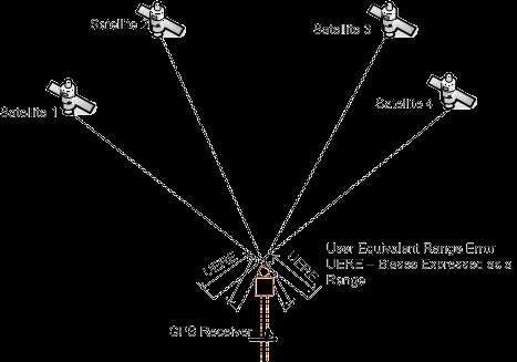
20 could be improved by supplementing GPS with other sensors, for example, the pseudolites Other commonly used DOP forms include the time dilution of precision (TDOP) and the geometric dilution of precision (GDOP). GDOP represents the combined effect of the PDOP and the TDOP. To ensure high-precision GPS positioning, it is recommended that a suitable observation time be selected to obtain the highest possible accuracy. A PDOP of five or less is usually recommended. In fact, the actual PDOP value is usually much less than five, with a typical average value in the neighborhood of two. Most GPS software packages have the ability to predict the satellite geometry based on the user's approximate location and the approximate satellite locations obtained from a recent almanac file for the GPS constellation. The almanac file is obtained as part of the navigation message, and can be downloaded free of charge over the Internet (e.g., from the U.S. Coast Guard Navigation Center. Fig.6a: good satellite geometry Fig.6b: bad satellite geometry User equivalent range error It has been shown that the GPS positioning accuracy is measured by the combined effect of the unmodeled measurement errors and the effect of the satellite geometry. The unmodeled measurement errors will certainly be different from one satellite to another, mainly because of the various
21 view angles. In addition, the ranging errors for the various satellites will have a certain degree of similarity. To rigorously determine the expected GPS positioning accuracy, we may apply an estimation technique such as the least squares method.the least squares method estimates the user's position (location) as well as its covariance matrix. The latter tells us how well the user's position is determined. In fact, the covariance matrix reflects the combined effect of the measurement errors and the satellite geometry. A more simplified way of examining the GPS positioning accuracy may be achieved through the introduction of the user equivalent range error. Assuming that the measurement errors for all the satellites are identical and independent, then a quantity known as the UERE may be defined as the root sum square of the various errors and biases. Multiplying the UERE by the appropriate DOP value produces the expected precision of the GPS positioning at the one sigma (1-a) level. To obtain the precision at the 2-a level, sometimes referred to as approximately 95% of the time, we multiply the results by a factor of two. For example, assuming that the UERE is 8m for the standalone GPS receiver, and taking a typical value of HDOP as 1.5, then the 95% positional accuracy will be 8 x1.5x2 = 24m.

22 Fig.7: User equivalent range error Source:
Global Positioning System: what it is and how we use it for measuring the earth s movement. May 5, 2009
 Global Positioning System: what it is and how we use it for measuring the earth s movement. May 5, 2009 References Lectures from K. Larson s Introduction to GNSS http://www.colorado.edu/engineering/asen/
Modelling GPS Observables for Time Transfer
 Modelling GPS Observables for Time Transfer Marek Ziebart Department of Geomatic Engineering University College London Presentation structure Overview of GPS Time frames in GPS Introduction to GPS observables
FieldGenius Technical Notes GPS Terminology
 FieldGenius Technical Notes GPS Terminology Almanac A set of Keplerian orbital parameters which allow the satellite positions to be predicted into the future. Ambiguity An integer value of the number of
Resection. We can measure direction in the real world! Lecture 10: Position Determination. Resection Example: Isola, Slovenia. Professor Keith Clarke
 Geography 12: Maps and Spatial Reasoning Lecture 10: Position Determination We can measure direction in the real world! Professor Keith Clarke Resection Resection Example: Isola, Slovenia Back azimuth
UNIT 1 - introduction to GPS
 UNIT 1 - introduction to GPS 1. GPS SIGNAL Each GPS satellite transmit two signal for positioning purposes: L1 signal (carrier frequency of 1,575.42 MHz). Modulated onto the L1 carrier are two pseudorandom
GLOBAL POSITIONING SYSTEMS. Knowing where and when
 GLOBAL POSITIONING SYSTEMS Knowing where and when Overview Continuous position fixes Worldwide coverage Latitude/Longitude/Height Centimeter accuracy Accurate time Feasibility studies begun in 1960 s.
What is a GPS How does GPS work? GPS Segments GPS P osition Position Position Accuracy Accuracy Accuracy GPS A pplications Applications Applications
 What is GPS? What is a GPS How does GPS work? GPS Segments GPS Position Accuracy GPS Applications What is GPS? The Global Positioning System (GPS) is a precise worldwide radio-navigation system, and consists
The Global Positioning System
 The Global Positioning System 5-1 US GPS Facts of Note DoD navigation system First launch on 22 Feb 1978, fully operational in 1994 ~$15 billion (?) invested to date 24 (+/-) Earth-orbiting satellites
Errors in GPS. Errors in GPS. Geodetic Co-ordinate system. R. Khosla Fall Semester
 Errors in GPS Errors in GPS GPS is currently the most accurate positioning system available globally. Although we are talking about extreme precision and measuring distances by speed of light, yet there
PDHonline Course L105 (12 PDH) GPS Surveying. Instructor: Jan Van Sickle, P.L.S. PDH Online PDH Center
 GPS Surveying. Instructor: Jan Van Sickle, P.L.S. PDH Online PDH Center") PDHonline Course L105 (12 PDH) GPS Surveying Instructor: Jan Van Sickle, P.L.S. 2012 PDH Online PDH Center 5272 Meadow Estates Drive Fairfax, VA 22030-6658 Phone & Fax: 703-988-0088 www.pdhonline.org www.pdhcenter.com
PDHonline Course L105 (12 PDH) GPS Surveying Instructor: Jan Van Sickle, P.L.S. 2012 PDH Online PDH Center 5272 Meadow Estates Drive Fairfax, VA 22030-6658 Phone & Fax: 703-988-0088 www.pdhonline.org www.pdhcenter.com
GPS Milestones, cont. GPS Milestones. The Global Positioning Sytem, Part 1 10/10/2017. M. Helper, GEO 327G/386G, UT Austin 1. US GPS Facts of Note
 The Global Positioning System US GPS Facts of Note DoD navigation system First launch on 22 Feb 1978, fully operational in 1994 ~$15 billion (?) invested to date 24 (+/-) Earth-orbiting satellites (SVs)
Global Navigation Satellite Systems II
 Global Navigation Satellite Systems II AERO4701 Space Engineering 3 Week 4 Last Week Examined the problem of satellite coverage and constellation design Looked at the GPS satellite constellation Overview
Sources of Error in Satellite Navigation Positioning
 http://www.transnav.eu the International Journal on Marine Navigation and Safety of Sea Transportation Volume 11 Number 3 September 2017 DOI: 10.12716/1001.11.03.04 Sources of Error in Satellite Navigation
Chapter 6 GPS Relative Positioning Determination Concepts
 Chapter 6 GPS Relative Positioning Determination Concepts 6-1. General Absolute positioning, as discussed earlier, will not provide the accuracies needed for most USACE control projects due to existing
The GLOBAL POSITIONING SYSTEM James R. Clynch February 2006
 The GLOBAL POSITIONING SYSTEM James R. Clynch February 2006 I. Introduction What is GPS The Global Positioning System, or GPS, is a satellite based navigation system developed by the United States Defense
Fundamentals of GPS Navigation
 Fundamentals of GPS Navigation Kiril Alexiev 1 /76 2 /76 At the traditional January media briefing in Paris (January 18, 2017), European Space Agency (ESA) General Director Jan Woerner explained the knowns
Multipath Error Detection Using Different GPS Receiver s Antenna
 Multipath Error Detection Using Different GPS Receiver s Antenna Md. Nor KAMARUDIN and Zulkarnaini MAT AMIN, Malaysia Key words: GPS, Multipath error detection, antenna residual SUMMARY The use of satellite
Introduction to the Global Positioning System
 GPS for Fire Management - 2004 Introduction to the Global Positioning System Pre-Work Pre-Work Objectives Describe at least three sources of GPS signal error, and identify ways to mitigate or reduce those
GPS and Recent Alternatives for Localisation. Dr. Thierry Peynot Australian Centre for Field Robotics The University of Sydney
 GPS and Recent Alternatives for Localisation Dr. Thierry Peynot Australian Centre for Field Robotics The University of Sydney Global Positioning System (GPS) All-weather and continuous signal system designed
CHAPTER 2 GPS GEODESY. Estelar. The science of geodesy is concerned with the earth by quantitatively
 CHAPTER 2 GPS GEODESY 2.1. INTRODUCTION The science of geodesy is concerned with the earth by quantitatively describing the coordinates of each point on the surface in a global or local coordinate system.
Space Weather and the Ionosphere
 Dynamic Positioning Conference October 17-18, 2000 Sensors Space Weather and the Ionosphere Grant Marshall Trimble Navigation, Inc. Note: Use the Page Down key to view this presentation correctly Space
PRINCIPLES AND FUNCTIONING OF GPS/ DGPS /ETS ER A. K. ATABUDHI, ORSAC
 PRINCIPLES AND FUNCTIONING OF GPS/ DGPS /ETS ER A. K. ATABUDHI, ORSAC GPS GPS, which stands for Global Positioning System, is the only system today able to show you your exact position on the Earth anytime,
Introduction to the Global Positioning System
 GPS for ICS - 2003 Introduction to the Global Positioning System Pre-Work Pre-Work Objectives Describe at least three sources of GPS signal error, and ways to mitigate or reduce those errors. Identify
Digital Land Surveying and Mapping (DLS and M) Dr. Jayanta Kumar Ghosh Department of Civil Engineering Indian Institute of Technology, Roorkee
 Dr. Jayanta Kumar Ghosh Department of Civil Engineering Indian Institute of Technology, Roorkee") Digital Land Surveying and Mapping (DLS and M) Dr. Jayanta Kumar Ghosh Department of Civil Engineering Indian Institute of Technology, Roorkee Lecture 11 Errors in GPS Observables Welcome students. Lesson
Digital Land Surveying and Mapping (DLS and M) Dr. Jayanta Kumar Ghosh Department of Civil Engineering Indian Institute of Technology, Roorkee Lecture 11 Errors in GPS Observables Welcome students. Lesson
ESTIMATION OF IONOSPHERIC DELAY FOR SINGLE AND DUAL FREQUENCY GPS RECEIVERS: A COMPARISON
 ESTMATON OF ONOSPHERC DELAY FOR SNGLE AND DUAL FREQUENCY GPS RECEVERS: A COMPARSON K. Durga Rao, Dr. V B S Srilatha ndira Dutt Dept. of ECE, GTAM UNVERSTY Abstract: Global Positioning System is the emerging
Global Correction Services for GNSS
 Global Correction Services for GNSS Hemisphere GNSS Whitepaper September 5, 2015 Overview Since the early days of GPS, new industries emerged while existing industries evolved to use position data in real-time.
Reading 28 PROPAGATION THE IONOSPHERE
 Reading 28 Ron Bertrand VK2DQ http://www.radioelectronicschool.com PROPAGATION THE IONOSPHERE The ionosphere is a region of the upper atmosphere extending from a height of about 60 km to greater than 500
Introduction to NAVSTAR GPS
 Introduction to NAVSTAR GPS Charlie Leonard, 1999 (revised 2001, 2002) The History of GPS Feasibility studies begun in 1960 s. Pentagon appropriates funding in 1973. First satellite launched in 1978. System
GPS: The Basics. Darrell R. Dean, Jr. Civil and Environmental Engineering West Virginia University. Expected Learning Outcomes for GPS
 GPS: The Basics Darrell R. Dean, Jr. Civil and Environmental Engineering West Virginia University Expected Learning Outcomes for GPS Explain the acronym GPS Name 3 important tdt dates in history of GPS
GPS Tutorial Trimble Home > GPS Tutorial > How GPS works? > Triangulating
 http://www.trimble.com/gps/howgps-triangulating.shtml Page 1 of 3 Trimble Worldwide Popula PRODUCTS & SOLUTIONS SUPPORT & TRAINING ABOUT TRIMBLE INVESTORS GPS Tutorial Trimble Home > GPS Tutorial > How
E. Calais Purdue University - EAS Department Civil 3273
 E. Calais Purdue University - EAS Department Civil 373 ecalais@purdue.edu GPS signal propagation GPS signal (= carrier phase modulated by satellite PRN code) sent by satellite. About 66 msec (0,000 km)
Appendix D Brief GPS Overview
 Appendix D Brief GPS Overview Global Positioning System (GPS) Theory What is GPS? The Global Positioning System (GPS) is a satellite-based navigation system, providing position information, accurate to
Global Positioning Systems (GPS) Trails: the achilles heel of mapping from the air / satellites
 Trails: the achilles heel of mapping from the air / satellites") Global Positioning Systems (GPS) Trails: the achilles heel of mapping from the air / satellites Google maps updated regularly by local users using GPS Also: http://openstreetmaps.org GPS applications
Global Positioning Systems (GPS) Trails: the achilles heel of mapping from the air / satellites Google maps updated regularly by local users using GPS Also: http://openstreetmaps.org GPS applications
LOCAL IONOSPHERIC MODELLING OF GPS CODE AND CARRIER PHASE OBSERVATIONS
 Survey Review, 40, 309 pp.71-84 (July 008) LOCAL IONOSPHERIC MODELLING OF GPS CODE AND CARRIER PHASE OBSERVATIONS H. Nahavandchi and A. Soltanpour Norwegian University of Science and Technology, Division
Table of Contents. Frequently Used Abbreviation... xvii
 GPS Satellite Surveying, 2 nd Edition Alfred Leick Department of Surveying Engineering, University of Maine John Wiley & Sons, Inc. 1995 (Navtech order #1028) Table of Contents Preface... xiii Frequently
Tajul Ariffin Musa. Tajul A. Musa. Dept. of Geomatics Eng, FKSG, Universiti Teknologi Malaysia, Skudai, Johor, MALAYSIA.
 Tajul Ariffin Musa Dept. of Geomatics Eng, FKSG, Universiti Teknologi Malaysia, 81310 Skudai, Johor, MALAYSIA. Phone : +6075530830;+6075530883; Mobile : +60177294601 Fax : +6075566163 E-mail : tajul@fksg.utm.my
Global Positioning System (GPS) Positioning Errors During Ionospheric Scintillation Event. Keywords: GPS; scintillation; positioning error
 Positioning Errors During Ionospheric Scintillation Event. Keywords: GPS; scintillation; positioning error") Jurnal Teknologi Full paper Global Positioning System (GPS) Positioning Errors During Ionospheric Scintillation Event Y. H. Ho a*, S. Abdullah b, M. H. Mokhtar b a Faculty of Electronic and Computer Engineering,
Jurnal Teknologi Full paper Global Positioning System (GPS) Positioning Errors During Ionospheric Scintillation Event Y. H. Ho a*, S. Abdullah b, M. H. Mokhtar b a Faculty of Electronic and Computer Engineering,
Broadcast Ionospheric Model Accuracy and the Effect of Neglecting Ionospheric Effects on C/A Code Measurements on a 500 km Baseline
 Broadcast Ionospheric Model Accuracy and the Effect of Neglecting Ionospheric Effects on C/A Code Measurements on a 500 km Baseline Intro By David MacDonald Waypoint Consulting May 2002 The ionosphere
Bernese GPS Software 4.2
 Bernese GPS Software 4.2 Introduction Signal Processing Geodetic Use Details of modules Bernese GPS Software 4.2 Highest Accuracy GPS Surveys Research and Education Big Permanent GPS arrays Commercial
Precise Positioning with NovAtel CORRECT Including Performance Analysis
 Precise Positioning with NovAtel CORRECT Including Performance Analysis NovAtel White Paper April 2015 Overview This article provides an overview of the challenges and techniques of precise GNSS positioning.
Phase Center Calibration and Multipath Test Results of a Digital Beam-Steered Antenna Array
 Phase Center Calibration and Multipath Test Results of a Digital Beam-Steered Antenna Array Kees Stolk and Alison Brown, NAVSYS Corporation BIOGRAPHY Kees Stolk is an engineer at NAVSYS Corporation working
GNSS Surveying & Processing (A Surveyors Peek Behind the Curtain) Presented by Jeff Clark, PLS
 Presented by Jeff Clark, PLS") GNSS Surveying & Processing (A Surveyors Peek Behind the Curtain) Presented by Jeff Clark, PLS Global Positioning System (GPS) (GNSS) GPS is considered a passive system Passive in the sense that only the
GNSS Surveying & Processing (A Surveyors Peek Behind the Curtain) Presented by Jeff Clark, PLS Global Positioning System (GPS) (GNSS) GPS is considered a passive system Passive in the sense that only the
RADIO WAVE PROPAGATION
 CHAPTER 2 RADIO WAVE PROPAGATION Radio direction finding (RDF) deals with the direction of arrival of radio waves. Therefore, it is necessary to understand the basic principles involved in the propagation
What is GPS? GPS Position Accuracy. GPS Applications. What is a GPS. How does GPS work? GPS Segments
 What is GPS? What is a GPS How does GPS work? GPS Segments GPS Position Accuracy GPS Applications 1 What is GPS? The Global Positioning System (GPS) is a precise worldwide radio-navigation system, and
Effects of magnetic storms on GPS signals
 Effects of magnetic storms on GPS signals Andreja Sušnik Supervisor: doc.dr. Biagio Forte Outline 1. Background - GPS system - Ionosphere 2. Ionospheric Scintillations 3. Experimental data 4. Conclusions
An Introduction to GPS
 An Introduction to GPS You are here The GPS system: what is GPS Principles of GPS: how does it work Processing of GPS: getting precise results Yellowstone deformation: an example What is GPS? System to
Lecture 8: GIS Data Error & GPS Technology
 Lecture 8: GIS Data Error & GPS Technology A. Introduction We have spent the beginning of this class discussing some basic information regarding GIS technology. Now that you have a grasp of the basic terminology
Introduction to GNSS
 Introduction to GNSS Dimitrios Bolkas, Ph.D. Department of Surveying Engineering, Pennsylvania State University, Wilkes Barre Campus PSLS Surveyor s Conference Hershey, PA Global Navigation Satellite System
Problem Areas of DGPS
 DYNAMIC POSITIONING CONFERENCE October 13 14, 1998 SENSORS Problem Areas of DGPS R. H. Prothero & G. McKenzie Racal NCS Inc. (Houston) Table of Contents 1.0 ABSTRACT... 2 2.0 A TYPICAL DGPS CONFIGURATION...
NAVIGATION SYSTEMS PANEL (NSP) NSP Working Group meetings. Impact of ionospheric effects on SBAS L1 operations. Montreal, Canada, October, 2006
 NSP Working Group meetings. Impact of ionospheric effects on SBAS L1 operations. Montreal, Canada, October, 2006") NAVIGATION SYSTEMS PANEL (NSP) NSP Working Group meetings Agenda Item 2b: Impact of ionospheric effects on SBAS L1 operations Montreal, Canada, October, 26 WORKING PAPER CHARACTERISATION OF IONOSPHERE
NAVIGATION SYSTEMS PANEL (NSP) NSP Working Group meetings Agenda Item 2b: Impact of ionospheric effects on SBAS L1 operations Montreal, Canada, October, 26 WORKING PAPER CHARACTERISATION OF IONOSPHERE
GPS POSITIONING GUIDE
 GPS POSITIONING GUIDE (July 1993) Third printing July 1995 This product is available from: Natural Resources Canada* Geomatics Canada Geodetic Survey Division Information Services 615 Booth Street Ottawa,
Trimble Business Center:
 Trimble Business Center: Modernized Approaches for GNSS Baseline Processing Trimble s industry-leading software includes a new dedicated processor for static baselines. The software features dynamic selection
Primer on GPS Operations
 MP Rugged Wireless Modem Primer on GPS Operations 2130313 Rev 1.0 Cover illustration by Emma Jantz-Lee (age 11). An Introduction to GPS This primer is intended to provide the foundation for understanding
Fundamentals of GPS for high-precision geodesy
 Fundamentals of GPS for high-precision geodesy T. A. Herring M. A. Floyd R. W. King Massachusetts Institute of Technology, Cambridge, MA, USA UNAVCO Headquarters, Boulder, Colorado, USA 19 23 June 2017
TEST YOUR SATELLITE NAVIGATION PERFORMANCE ON YOUR ANDROID DEVICE GLOSSARY
 TEST YOUR SATELLITE NAVIGATION PERFORMANCE ON YOUR ANDROID DEVICE GLOSSARY THE GLOSSARY This glossary aims to clarify and explain the acronyms used in GNSS and satellite navigation performance testing
Introduction to Geographic Information Science. Last Lecture. Today s Outline. Geography 4103 / GNSS/GPS Technology
 Geography 4103 / 5103 Introduction to Geographic Information Science GNSS/GPS Technology Last Lecture Geoids Ellipsoid Datum Projection Basics Today s Outline GNSS technology How satellite based navigation
1. Terrestrial propagation
 Rec. ITU-R P.844-1 1 RECOMMENDATION ITU-R P.844-1 * IONOSPHERIC FACTORS AFFECTING FREQUENCY SHARING IN THE VHF AND UHF BANDS (30 MHz-3 GHz) (Question ITU-R 218/3) (1992-1994) Rec. ITU-R PI.844-1 The ITU
Introduction to GNSS
 Introduction to GNSS Dimitrios Bolkas, Ph.D. Department of Surveying Engineering, Pennsylvania State University, Wilkes Barre Campus PSLS Surveyor s Conference January 21-24, 2018 Hershey, PA Global Navigation
Chapter 15: Radio-Wave Propagation
 Chapter 15: Radio-Wave Propagation MULTIPLE CHOICE 1. Radio waves were first predicted mathematically by: a. Armstrong c. Maxwell b. Hertz d. Marconi 2. Radio waves were first demonstrated experimentally
t =1 Transmitter #2 Figure 1-1 One Way Ranging Schematic
 1.0 Introduction OpenSource GPS is open source software that runs a GPS receiver based on the Zarlink GP2015 / GP2021 front end and digital processing chipset. It is a fully functional GPS receiver which
NR402 GIS Applications in Natural Resources
 NR402 GIS Applications in Natural Resources Lesson 5 GPS/GIS integration Global Positioning System (GPS)..a global navigation system that everyone can use What is GPS? How does it work? How accurate is
3D-Map Aided Multipath Mitigation for Urban GNSS Positioning
 Summer School on GNSS 2014 Student Scholarship Award Workshop August 2, 2014 3D-Map Aided Multipath Mitigation for Urban GNSS Positioning I-Wen Chu National Cheng Kung University, Taiwan. Page 1 Outline
Mitigate Effects of Multipath Interference at GPS Using Separate Antennas
 Mitigate Effects of Multipath Interference at GPS Using Separate Antennas Younis H. Karim AlJewari #1, R. Badlishah Ahmed *2, Ali Amer Ahmed #3 # School of Computer and Communication Engineering, Universiti
Polarization orientation of the electric field vector with respect to the earth s surface (ground).
.") Free space propagation of electromagnetic waves is often called radio-frequency (rf) propagation or simply radio propagation. The earth s atmosphere, as medium introduces losses and impairments to the
Free space propagation of electromagnetic waves is often called radio-frequency (rf) propagation or simply radio propagation. The earth s atmosphere, as medium introduces losses and impairments to the
Session2 Antennas and Propagation
 Wireless Communication Presented by Dr. Mahmoud Daneshvar Session2 Antennas and Propagation 1. Introduction Types of Anttenas Free space Propagation 2. Propagation modes 3. Transmission Problems 4. Fading
Integration of GPS with a Rubidium Clock and a Barometer for Land Vehicle Navigation
 Integration of GPS with a Rubidium Clock and a Barometer for Land Vehicle Navigation Zhaonian Zhang, Department of Geomatics Engineering, The University of Calgary BIOGRAPHY Zhaonian Zhang is a MSc student
CHAPTER 2 WIRELESS CHANNEL
 CHAPTER 2 WIRELESS CHANNEL 2.1 INTRODUCTION In mobile radio channel there is certain fundamental limitation on the performance of wireless communication system. There are many obstructions between transmitter
MINIMIZING SELECTIVE AVAILABILITY ERROR ON TOPEX GPS MEASUREMENTS. S. C. Wu*, W. I. Bertiger and J. T. Wu
 MINIMIZING SELECTIVE AVAILABILITY ERROR ON TOPEX GPS MEASUREMENTS S. C. Wu*, W. I. Bertiger and J. T. Wu Jet Propulsion Laboratory California Institute of Technology Pasadena, California 9119 Abstract*
Proceedings of Al-Azhar Engineering 7 th International Conference Cairo, April 7-10, 2003.
 Proceedings of Al-Azhar Engineering 7 th International Conference Cairo, April 7-10, 2003. MODERNIZATION PLAN OF GPS IN 21 st CENTURY AND ITS IMPACTS ON SURVEYING APPLICATIONS G. M. Dawod Survey Research
Space Weather influence on satellite based navigation and precise positioning
 Space Weather influence on satellite based navigation and precise positioning R. Warnant, S. Lejeune, M. Bavier Royal Observatory of Belgium Avenue Circulaire, 3 B-1180 Brussels (Belgium) What this talk
GNSS Technologies. PPP and RTK
 PPP and RTK 29.02.2016 Content Carrier phase based positioning PPP RTK VRS Slides based on: GNSS Applications and Methods, by S. Gleason and D. Gebre-Egziabher (Eds.), Artech House Inc., 2009 http://www.gnssapplications.org/
Antennas and Propagation
 Antennas and Propagation Chapter 5 Introduction An antenna is an electrical conductor or system of conductors Transmission - radiates electromagnetic energy into space Reception - collects electromagnetic
UCGE Reports Number 20054
 UCGE Reports Number 20054 Department of Geomatics Engineering An Analysis of Some Critical Error Sources in Static GPS Surveying (URL: http://www.geomatics.ucalgary.ca/links/gradtheses.html) by Weigen
Effect of Quasi Zenith Satellite (QZS) on GPS Positioning
 on GPS Positioning") Effect of Quasi Zenith Satellite (QZS) on GPS ing Tomoji Takasu 1, Takuji Ebinuma 2, and Akio Yasuda 3 Laboratory of Satellite Navigation, Tokyo University of Marine Science and Technology 1 (Tel: +81-5245-7365,
Effect of Quasi Zenith Satellite (QZS) on GPS ing Tomoji Takasu 1, Takuji Ebinuma 2, and Akio Yasuda 3 Laboratory of Satellite Navigation, Tokyo University of Marine Science and Technology 1 (Tel: +81-5245-7365,
GPS STATIC-PPP POSITIONING ACCURACY VARIATION WITH OBSERVATION RECORDING INTERVAL FOR HYDROGRAPHIC APPLICATIONS (ASWAN, EGYPT)
") GPS STATIC-PPP POSITIONING ACCURACY VARIATION WITH OBSERVATION RECORDING INTERVAL FOR HYDROGRAPHIC APPLICATIONS (ASWAN, EGYPT) Ashraf Farah Associate Professor,College of Engineering, Aswan University,
GPS STATIC-PPP POSITIONING ACCURACY VARIATION WITH OBSERVATION RECORDING INTERVAL FOR HYDROGRAPHIC APPLICATIONS (ASWAN, EGYPT) Ashraf Farah Associate Professor,College of Engineering, Aswan University,
Integrity of Satellite Navigation in the Arctic
 Integrity of Satellite Navigation in the Arctic TODD WALTER & TYLER REID STANFORD UNIVERSITY APRIL 2018 Satellite Based Augmentation Systems (SBAS) in 2018 2 SBAS Networks in 2021? 3 What is Meant by Integrity?
TREATMENT OF DIFFRACTION EFFECTS CAUSED BY MOUNTAIN RIDGES
 TREATMENT OF DIFFRACTION EFFECTS CAUSED BY MOUNTAIN RIDGES Rainer Klostius, Andreas Wieser, Fritz K. Brunner Institute of Engineering Geodesy and Measurement Systems, Graz University of Technology, Steyrergasse
Principles of the Global Positioning System Lecture 19
 12.540 Principles of the Global Positioning System Lecture 19 Prof. Thomas Herring http://geoweb.mit.edu/~tah/12.540 GPS Models and processing Summary: Finish up modeling aspects Rank deficiencies Processing
Sw earth Dw Direct wave GRw Ground reflected wave Sw Surface wave
 WAVE PROPAGATION By Marcel H. De Canck, ON5AU Electromagnetic radio waves can propagate in three different ways between the transmitter and the receiver. 1- Ground waves 2- Troposphere waves 3- Sky waves
GPS for. Land Surveyors. Jan Van Sickle. Fourth Edition. CRC Press. Taylor & Francis Group. Taylor & Francis Croup, an Informa business
 GPS for Land Surveyors Fourth Edition Jan Van Sickle CRC Press Taylor & Francis Group Boca Raton London New York CRC Press is an imprint of the Taylor & Francis Croup, an Informa business Contents Preface
3. Radio Occultation Principles
 Page 1 of 6 [Up] [Previous] [Next] [Home] 3. Radio Occultation Principles The radio occultation technique was first developed at the Stanford University Center for Radar Astronomy (SUCRA) for studies of
Sources of Geographic Information
 Sources of Geographic Information Data properties: Spatial data, i.e. data that are associated with geographic locations Data format: digital (analog data for traditional paper maps) Data Inputs: sampled
Dynamic Positioning TCommittee
 RETURN TO DIRETORetr Dynamic Positioning TCommittee PMarine Technology Society DYNAMIC POSITIONING CONFERENCE October 17 18, 2000 ADVANCES IN TECHNOLOGY Removal of GPS Selective Availability - Consequences
GNSS & Coordinate Systems
 GNSS & Coordinate Systems Matthew McAdam, Marcelo Santos University of New Brunswick, Department of Geodesy and Geomatics Engineering, Fredericton, NB May 29, 2012 Santos, 2004 msantos@unb.ca 1 GNSS GNSS
GPS Errors. Figure 1. Four satellites are required to determine a GPS position.
 Expl ai ni nggps:thegl obalposi t i oni ngsyst em since a minimum of four satellites is required to calculate a position (Fig 1). However, many newer GPS receivers are equipped to receive up to 12 satellite
Guochang Xu GPS. Theory, Algorithms and Applications. Second Edition. With 59 Figures. Sprin ger
 Guochang Xu GPS Theory, Algorithms and Applications Second Edition With 59 Figures Sprin ger Contents 1 Introduction 1 1.1 AKeyNoteofGPS 2 1.2 A Brief Message About GLONASS 3 1.3 Basic Information of Galileo
Chapter 5. Clock Offset Due to Antenna Rotation
 Chapter 5. Clock Offset Due to Antenna Rotation 5. Introduction The goal of this experiment is to determine how the receiver clock offset from GPS time is affected by a rotating antenna. Because the GPS
Antennas and Propagation. Chapter 5
 Antennas and Propagation Chapter 5 Introduction An antenna is an electrical conductor or system of conductors Transmission - radiates electromagnetic energy into space Reception - collects electromagnetic
Global Positioning Systems - GPS
 Global Positioning Systems - GPS GPS Why? What is it? How does it work? Differential GPS How can it help me? GPS Why?? Where am I? How do I get there? Where are you, and how do I get to You? WHO CARES???
Using a Sky Projection to Evaluate Pseudorange Multipath and to Improve the Differential Pseudorange Position
 Using a Sky Projection to Evaluate Pseudorange Multipath and to Improve the Differential Pseudorange Position Dana G. Hynes System Test Group, NovAtel Inc. BIOGRAPHY Dana Hynes has been creating software
Introduction. Global Positioning System. GPS - Intro. Space Segment. GPS - Intro. Space Segment - Contd..
 Introduction Global Positioning System Prof. D. Nagesh Kumar Dept. of Civil Engg., IISc, Bangalore 560 012, India URL: http://www.civil.iisc.ernet.in/~nagesh GPS is funded and controlled by U. S. Department
Study of small scale plasma irregularities. Đorđe Stevanović
 Study of small scale plasma irregularities in the ionosphere Đorđe Stevanović Overview 1. Global Navigation Satellite Systems 2. Space weather 3. Ionosphere and its effects 4. Case study a. Instruments
GLOBAL NAVIGATION SATELLITE SYSTEMS (GNSS) ECE 2526E Tuesday, 24 April 2018
 ECE 2526E Tuesday, 24 April 2018") GLOBAL NAVIGATION SATELLITE SYSTEMS (GNSS) ECE 2526E Tuesday, 24 April 2018 MAJOR GLOBAL NAVIGATION SATELLITE SYSTEMS (GNSS) Global Navigation Satellite System (GNSS) includes: 1. Global Position System
GLOBAL NAVIGATION SATELLITE SYSTEMS (GNSS) ECE 2526E Tuesday, 24 April 2018 MAJOR GLOBAL NAVIGATION SATELLITE SYSTEMS (GNSS) Global Navigation Satellite System (GNSS) includes: 1. Global Position System
UNIT Derive the fundamental equation for free space propagation?
 UNIT 8 1. Derive the fundamental equation for free space propagation? Fundamental Equation for Free Space Propagation Consider the transmitter power (P t ) radiated uniformly in all the directions (isotropic),
GPS Basics. Introduction to GPS (Global Positioning System) Version 1.0 English
 Version 1.0 English") 20 30 40 50 GPS Basics Introduction to GPS (Global Positioning System) Version 1.0 English Contents Preface... 4 1. What is GPS and what does it do?... 5 2. System Overview... 6 2.1 The Space Segment...
20 30 40 50 GPS Basics Introduction to GPS (Global Positioning System) Version 1.0 English Contents Preface... 4 1. What is GPS and what does it do?... 5 2. System Overview... 6 2.1 The Space Segment...
Antennas and Propagation
 CMPE 477 Wireless and Mobile Networks Lecture 3: Antennas and Propagation Antennas Propagation Modes Line of Sight Transmission Fading in the Mobile Environment Introduction An antenna is an electrical
Global Positioning Systems -GPS
 Global Positioning Systems -GPS GPS Why? What is it? How does it work? Differential GPS How can it help me? GPS Why?? Where am I? How do I get there? Where are you, and how do I get to You? WHO CARES???
ENGI 3703 Surveying and Geomatics
 Satellite Geometry: Satellites well spread out in the sky have a much stronger solution to the resection type problem (aka trilateration) then satellite that are grouped together. Since the position of
DYNAMIC POSITIONING CONFERENCE October 17 18, 2000 SENSORS. Space Weather and the Ionosphere. Grant Marshall Trimble Navigation Inc.
 DYNAMIC POSIIONING CONFERENCE October 17 18, 2000 SENSORS Space Weather and the Ionosphere Grant Marshall rimble Navigation Inc. Images shown here are part of an animated presentation and may not appear
RECOMMENDATION ITU-R P Prediction of sky-wave field strength at frequencies between about 150 and khz
 Rec. ITU-R P.1147-2 1 RECOMMENDATION ITU-R P.1147-2 Prediction of sky-wave field strength at frequencies between about 150 and 1 700 khz (Question ITU-R 225/3) (1995-1999-2003) The ITU Radiocommunication