Solar Storm Probabilities Grid Contingencies Harmonic Relay Settings
|
|
|
- Laurence Eaton
- 5 years ago
- Views:
Transcription


1 Presentation to NERC GMD Meeting March 18 th 19 th, 2014 SolidGround TM Transformer Neutral Blocking System Solar Storm Probabilities Grid Contingencies Harmonic Relay Settings
2 Agenda US Power Usage and the One in 100 Year Storm When will next Extreme Storm Hit? New Contingency Modeling Results for the ATC Power Grid Potential Damage to Generator Rotors by GIC produced Harmonics and Harmonic Relay Settings Solid Ground Installation status in the Wisconsin ATC Grid
3 Total US Energy Usage (Billions of Kilo Watt Hours) [1] From J. Kappenman, Great Geomagnetic Storms., Adv. In Space Research 38, (2006), p Rate of Change of Magnetic Field (nt/min) US Electrical Power Usage & GMD Events 5,000 4,500 4,000 3,500 3, ,800 nt/min Carrington Storm [1] ,800 nt/min NY Railroad Storm [1] 6,000 5,000 4,000 2,500 3,000 2,000 1,500 1, Quebec ~ 500 nt/min ~ 2 V/km 2003 Storm 0 ~ 1 V/km Years 2,000 1,000
 Quebec Statistics of Geo-Electric Fields calculated from Geomagnetic recordings from 1993 through 2006 Geo-Electric Field 20 V/km, range 10")
4 Geo-Electric Fields for a Severe Solar Strom a) British Col. b) Quebec Statistics of Geo-Electric Fields calculated from Geomagnetic recordings from 1993 through 2006 Geo-Electric Field 20 V/km, range 10 to 50 V/km [2] [2] From A. Pulkkinen et.al. are from Space Weather publication in 2012
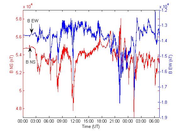
5 Geomagnetic Latitude is much different than Geographic Latitude Northern FL at 40 deg Magnetic Lat. GMD records show impact of weak storms (Aug 14, 2003) cover nearly all of North America (40 deg & greater magnetic latitude) [1] [1] Taken from A. Pulkkinen et.al. are from Space Weather publication in 2012
6 Probability of a Carrington Extreme Solar Storm Hitting the Earth The probability of time events that are continuous and independent of each other (i.e. a Poisson process) is given by an Exponential distribution Cum Probability is given by P(t) = 1 exp (-lt) where t is the time of occurrence of an event and l a single parameter fit to the data Four papers published in 2012 & 2013 address this question The authors used various long term solar storm recorded data sources The reported results are in remarkably good agreement
7 Probability of a Carrington Extreme Solar Storm Hitting the Earth The probability of time events that are continuous and independent of each other (i.e. a Poisson process) is given by an Exponential distribution; the Cum probability distribution is: P(t) = 1 exp (-lt) where t is the time of occurrence of an event and l a single parameter fit to the data [1] [1] Ross, Sheldon M. (2009). Introduction to probability and statistics for engineers and scientists (4th ed.). Associated Press. p ISBN Several papers published in 2012 & 2013 address this question; namely, P. Riley, R. Katakoa, J. F. Love and R. Thorberg All assume the Poisson process i.e. the time occurrence of events is independent The authors used various solar storm recorded data sources: P. Riley 45 yrs of NASA magnetic data and 10 yrs of CME speed data R. Katakoa 89 yrs of Kakioka Observatory, Japan, magnetic data J.F. Love 10 yrs of USA magnetic data R. Thorberg 60 yrs of Northern Eurpore magnetic data The results are in remarkably good agreement: But the lack of Extreme events give rise to Large Statistical Uncertainties
8 Probability a Carrington Storm (4,800 nt/min) will hit within 10, 20, 30 & 40 Years (data fit to Poisson Distribution) Published Predictions Predicted Probability (%) Within 10 Yrs Probability (%) Within 20 Yrs (Poisson Dist.) Probability (%) Within 30 Yrs (Poisson Dist.) Probability (%) Within 40 Yrs (Poisson Dist.) P. Riley [1] R. Katakoa [2] R. Thorberg [3] * J. F. Love [4] Weak Solar Cycles R. Katakoa [2] Weak Solar Cycles Riley, P. (2012), On the probability of occurrence of extreme space weather events, SpaceWeather, 10, S02012, doi: /2011sw Kataoka, R. (2013), Probability of occurrence of extreme magnetic storms, Space Weather, 11, doi: /swe Thorberg R., Division of Industrial Electrical Engineering and Automation Faculty of Engineering, LTH, Lund University ): Risk analysis of geomagnetically induced currents in power systems * Note Thorberg provided probability for event within 3 years (4.7%) which as been extended to the probability for a 10 year event. 4. Love, J. F. (2012), Credible occurrence probabilities for extreme geophysical events: Earthquakes, volcanic eruptions, magnetic storms, Geophys. Res. Lett., 39, L10301, doi: /2012gl
9 Cum Probability of an Extreme GMD Event (%) Cum Probability of an Extreme (Carrington) GMD Hitting the Earth versus Future Years 100% 90% 80% 70% 60% 50% 40% 30% 20% 10% 0% Thorberg Kataoka I Riley Love Kataoka II l =0.016 l = l =0.013 l = Years Projections Based on Long Term Solar Data Projections Based on Weak Solar Cycle 50 % Prob. at ~ 50 Years Three Independent Studies Give Similar Predictions for the Probability of a Carrington Extreme Storm
10 Cum Probability of an Extreme GMD Event (%) Cum Probability of an Extreme (Carrington) GMD Hitting the Earth versus Future Years 100% 90% 80% 70% 60% 50% 40% 30% 20% 10% 0% Thorberg Kataoka I Riley Love Kataoka II l =0.016 l = l =0.013 l = Error Bars from Love s Analysis Years Projections Based on Long Term Solar Data Projections Based on Weak Solar Cycle 50 % Prob. at ~ 50 Years Three Independent Studies Give Similar Predictions for the Probability of a Carrington Extreme Storm
11 Chester Maine GIC Storm Data Linear Projection to 100 Year Storm (5,000 nt/min) gives neutral current of: Minimum = 500 Amps Mean = 1,000 Amps Max = 2,000 Amps 250 nt/min Data taken from EIS submission to Maine PUC, Oct 4, 2013 ~ 100 Amperes

12 IEEE THD Voltage Standard 5% Potential for Upset and/or Damage to Customer Equipment
13 ATC Modeling Results of Voltage Collapse for three Conditions Operating System Conditions for ATC Power Grid Collapse Voltage (V/km) Peak Power, No Contingencies 22.0 Shoulder Load, No Contingencies 23.0 Shoulder Load w Medium Transfers, No Contingencies 20.5 Shoulder Load w High Transfers, No Contingencies 17.5 Power Grid Collapse Voltages were Calculated using PowerWorld LLC Modeling Software
14 Generation Impacts Rotor Heating Effects from GIC Conclusion by Gish et. al. Damage to a generator rotor is possible from GIC The primary cause of heating is negative sequence second harmonic and positive sequence fourth harmonic adding together on the rotor. Conventional negative-sequence overcurrent relays equipped with a sensitive alarm may provide satisfactory protection the trip may be adjusted to a per unit setting slightly above the standard limit with a 120 second timer. IEEE Transaction on Power Delivery, April 1994 Authors: Gish, Feero and Rockefeller
15 Generation Impacts Rotor Heating Effects from GIC Discussion by R. A. Walling: This paper describes a potentially grave consequences of GIC that is under appreciated by the industry. Although GIC-related damage of generators has not been documented, our analyses lead us to concur with authors that stator current harmonics during severe GMD can lead to rotor heating duty more severe than caused by operating at the maximum fundamental frequency negative sequence imbalance as defined by ANSI C IEEE Transaction on Power Delivery, April 1994 Authors: Gish, Feero and Rockefeller Commenter on the paper: R. A. Walling
16 Generation Impacts Generator Thermal Stress during a GMD Conclusions by Rezaei-Zare & L. Marti this study indicates that the relevant IEEE standards C50.12 and C50.13 require modifications to take into account the even harmonics of the generator current during a GMD event.. The standards underestimate the effective negative sequence current which contributes to the rotor heating. PESGM Authors: Rezaei-Zare and Luis Marti, IEEE PES, July 2013, Vancouver, Canada The simulation results reveal that the generator capability limit can be exceeded at moderate GIC levels, e.g. 50A/phase, and the rotor damage is likely during a severe GMD event.
17 Hobson s Choice Hobson s Choice to the industry: Let relays trip out generators Or Do nothing and chance damage to generators

18 ATC (Wisconsin) Grid Map Weston High Transfer Increase flow to ~ 95% of interface limit 2,600 MW of Generation shift
19 ATC Modeling Results of Voltage Collapse for Contingency Conditions Operating System Conditions for ATC Power Grid Collapse Voltage (V/km) Peak Power, No Contingencies 22.0 Shoulder Load w High Transfers, No Contingencies Loss of Largest Generator at One Site, High Transfers Loss of Largest Two Generators at One Site, High Transfers Loss of All Generation at One Site, High Transfers Power Grid Collapse Voltages were Calculated using PowerWorld LLC Modeling Software
20 ATC Modeling Results of Voltage Collapse for Contingency Conditions Operating System Conditions for ATC Power Grid Collapse Voltage (V/km) Period of Storm from Pulkkinen et. al. Statistics Peak Power, No Contingencies 22.0 ~ 100 Year Shoulder Load w High Transfers, No Contingencies Loss of Largest Generator at One Site, High Transfers 17.5 ~ 40 Year 16.6 ~ 30 Year Loss of Largest Two Generators at One Site, High Transfers Loss of All Generation at One Site, High Transfers 14.5 ~ 20 Year 12.4 ~ 10 Year Period of Storms were derived from A. Pulkkinen et.al. Storm Statistics from Space Weather publication in 2012
21 ATC Modeling Results of Voltage Collapse for Contingency Conditions Operating System Conditions for ATC Power Grid Collapse Voltage (V/km) Period of Storm from Pulkkinen et. al. Statistics Collapse Voltage after Blocking in 25 Substations Peak Power, No Contingencies 22.0 ~ 100 Year 31 Shoulder Load w High Transfers, No Contingencies Loss of Largest Generator at One Site, High Transfers 17.5 ~ 40 Year ~ 30 Year 25 Loss of Largest Two Generators at One Site, High Transfers Loss of All Generation at One Site, High Transfers 14.5 ~ 20 Year ~ 10 Year 18 Period of Storms were derived from A. Pulkkinen et.al. Storm Statistics from Space Weather publication in 2012
22 Voltage at Lowest pu Voltage Bus ATC Grid Voltage Collapse vs GMD Fields and Neutral Blocking Systems Voltage Performance, 60 degree storm, Summer Peak, No Transfers, No Contingencies Grid Collapse 22 V/ km Improvement with Neutral Blocking 30 V/ km Severe GMD Year Storm Prediction (20 V/km, range 10 to 50 V/km) [1] Base 5 Subs 10 Subs 15 Subs 20 Subs 25 Subs Field Strength (V/km) Neutral Blocking Significantly Improves Grid Voltage Collapse
23 Voltage at Lowest pu Voltage Bus ATC Grid Voltage Collapse vs GMD Fields and Neutral Blocking Systems Voltage Performance, 60 degrees Storm, Summer Shoulder with High Transfer, Weston Generation Outage Grid Collapse at 12 V/ km (10 Yr Event) Improvement with Neutral Blocking to 18 V/ km GMD 100 Year Storm Prediction (20 V/km, range 10 to 50 V/km) [1] Base 5 Subs 10 Subs 15 Subs 20 Subs 25 Subs Field Strength (V/km) Neutral Blocking Significantly Improves Grid Voltage Collapse

24 ATC SolidGround TM System Installation American Transmission Company, WI ATC has installed a SolidGround TM (SG-22) system at their Morgan sub-station in northern Wisconsin Reports will be shared with the appropriate NERC committees, EPRI and the power industry SEL Control Electronics Tested with SolidGround

25 First Wisconsin Installation SolidGround
26 GIC Simulation Tools Luis Marti Hydro One Networks Ontario, Canada
27 Focus of this presentation Geomagnetic Field Geoelectric Field Potential Mitigation Measures B(t) Earth Conductivity Model E(t) dc System Model GIC(t) Transformer Model (Electrical) Transformer Model (Thermal) vars Power Flow Analysis Temp(t) Hot Spot Temp. Bus Voltages Line Loading & var Reserves Assessment Criteria Fail Pass Operating Procedures and Mitigation Measures (if needed)
28 Calculation of the Geoelectric field Geomagnetic Field Geoelectric Field Potential Mitigation Measures B(t) Earth Conductivity Model E(t) dc System Model GIC(t) Transformer Model (Electrical) vars Power Flow Analysis Bus Voltages Line Loadi var Reser Transformer Model (Thermal) Temp(t) Hot Spot Temp. Calculation of E(t) from B(t) Data requirements Geomagnetic time series or waveshape B E (t) and B N (t) Earth conductivity model Result is the geoelectric field time series or waveshape E E (t) and E N (t)

29 Earth model

30 Geomagnetic field B(t)


31 Geoelectric field
32 Geoelectric Field Tool Extracted from Hydro One s real time GIC simulator Validated with closed-form waveshapes

33 B(t) Fmax = 10 mhz

34 E(t) Fmax = 10 mhz
35 E(t) Fmax = 10 mhz (close-up)
36 B(t) Fmax = 1 mhz

37 E(t) Fmax = 1 mhz
38 E(t) Fmax = 1 mhz (close-up)

39
40 Calculation of Thermal Response Geomagnetic Field Geoelectric Field Potential Mitigation Measures B(t) Earth Conductivity Model E(t) dc System Model GIC(t) Transformer Model (Electrical) Transformer Model (Thermal) vars Power Flow Analysis Temp(t) Hot Spot Temp. Bus Voltages Line Loading & var Reserves Assessment Criteria Fail Pass Operating Procedures and Mitigation Measures (if needed) Calculation of θ(t) from GIC(t) Data requirements GIC(t) for any gven transformer Thermal step response for winding and metallic hot spots for different GIC values Measured or Calculated
41 Thermal Response Tool Extracted from Hydro One s real time GIC and steady-state simulators Straightforward implementation of Marti, L., Rezaei-Zare, A., Narang, A., "Simulation of Transformer Hotspot Heating due to Geomagnetically Induced Currents," IEEE Transactions on Power Delivery,, vol.28, no.1, pp , Jan Most measured time constants seem to be in the same range so far More work on measurement-validated models are necessary for the asymptotic responses. A number of published measurements and calculations are in the same range Some manufacturers (notably Siemens and Von Roll) are working on their models so that they can reproduce measurements For now, we have very conservative models. Stay tuned.

42
43 Any more questions?
44 PowerWorld Simulator GIC NERC GMD Task Force March 19, South First Street Champaign, Illinois (217)


45 GIC Modeling Modern methods model GIC as DC voltage sources in transmission lines With pertinent parameters, GIC computation is a straightforward linear calculation By integrating GIC calculations into PowerWorld Simulator, engineers can readily see the impact of GICs on their systems and consider mitigation options PowerWorld Simulator GIC 2014 PowerWorld Corporation 2
46 GIC Analysis Inputs GIC calculations use some existing model parameters such as line resistance Some additional parameters are needed Substation geo-coordinates and grounding resistance Transformer grounding configuration, coil resistance, core type, whether auto-transformer, whether threewinding transformer Generator step-up transformer parameters Transmission operators would be in the best position to provide these values, but all can be estimated when actual values are not available PowerWorld Simulator GIC 2014 PowerWorld Corporation 3
47 GIC Analysis Outputs and Results GIC studies involve the traditional power system results (voltages, flows, etc.) and GIC-specific quantities, such as Transformer neutral amps Transformer Mvar losses Substation neutral dc voltages Bus dc voltages Transmission line dc amps Providing easy access to the data and results is a key objective in PowerWorld Simulator, as is good wide-area visualization PowerWorld Simulator GIC 2014 PowerWorld Corporation 4
48 GMD Storm Scenarios The starting point for GIC analysis is an assumed storm scenario; this is used to calculate transmission line DC input voltages Uniform surface electric field model: magnitude and direction Geospatially and time-varying electric field model Direct user input of GIC DC voltage input on each transmission line, OR External input files (*.csv) specifying a time-series geospatial grid of northward and eastward E-field magnitude PowerWorld Simulator GIC 2014 PowerWorld Corporation 5
 N 0 (south-north) 15 90 (west-east) 165 PowerWorld Simulator GIC 2014 PowerWorld Corporation")
49 Uniform Electric Field Modeling Electric-Field Magnitude (V/mile or V/km) Storm Direction (0 to 360 degrees) N 0 (south-north) (west-east) 165 PowerWorld Simulator GIC 2014 PowerWorld Corporation 6

50 Time-Varying DC Input Voltage Allows direct entry of GIC DC input voltage on each transmission line Can be initialized with uniform field assumptions, then optionally modified Calculation mode Time and Field input Click Add at Time PowerWorld Simulator GIC 2014 PowerWorld Corporation 7
51 Time and Geospatially-Varying Electric Field Read a non-uniform surface electric field specification from a set of external text (*.csv) files PowerWorld Simulator GIC 2014 PowerWorld Corporation 8
52 Geographic Information GMD-induced DC voltages depend on the storm strength and orientation and the latitude and longitude of the transmission lines The electric field is integrated along the path of the transmission line The geo-coordinates of the terminal buses are sufficient for uniform field modeling Hence buses must be mapped to substations, and substations to their geo-coordinates Substation/geographic data can be supplied by PowerWorld for FERC 715 planning models Buses mapped to substations Latitude and longitude for substations PowerWorld Simulator GIC 2014 PowerWorld Corporation 9
53 Grounding Resistance Substation grounding resistance is the resistance in ohms between the substation neutral and earth ground (zero-potential reference) An actual fall of potential test is the best way to determine this resistance Simulator provides defaults based on number of buses and highest nominal kv, but research has shown this to be a poor substitute for actual measurements Simulator defaults range from 0.1 to 2.0 Ω Substations with more buses and higher nominal kv are assumed to have lower grounding resistance PowerWorld Simulator GIC 2014 PowerWorld Corporation 10
54 Default Assumptions: Transformers It is always best to provide known quantities, especially for configuration and autotransformer fields If any transformer information is unknown, Simulator uses assumed values based on the power flow model Coil Resistance ohms per phase estimate based on positive-sequence AC per-unit series resistance and transformer impedance base Assumed split between each winding: RR pppp RR BBBBBBBB,HHHHHHHHHHHHHHH = RR HHHHHHHHHHHHHHH + aa tt 2 RR LLLLLLLLLLLLLL RR HHHHHHHHHHHHHHH = aa tt 2 RR LLLLLLLLLLLLLL PowerWorld Simulator GIC 2014 PowerWorld Corporation 11
55 Default Assumptions: Autotransformers Units are assumed to be autotransformers if all of the following criteria are met unit is not a phase-shifting transformer high side and low side are at different nominal voltages high side nominal voltage is at least 100 kv turns ratio is less than or equal to 3 These parameters may be adjusted at Options DC Current Calculation PowerWorld Simulator GIC 2014 PowerWorld Corporation 12


56 Default Assumptions: Transformer Configuration Unknown windings can be assumed Delta, Grounded Wye, or Ungrounded Wye Default transmission and distribution side configurations may be specified globally or by area PowerWorld Simulator GIC 2014 PowerWorld Corporation 13
57 Mapping Transformer GICs to Transformer Reactive Power Losses Transformer specific, and can vary widely with the core type: Single phase, shell, 3-legged, 5-legged Ideally this information would be supplied by the transformer owner For large system studies, default data may be used when nothing else is available. Scaling value changes with core type Simulator supports default values or a user-specified linear mapping Debate in the industry with respect to the magnitude of damage GICs would cause in transformers (from slightly age to permanently destroy) PowerWorld Simulator GIC 2014 PowerWorld Corporation 14
58 Default Assumptions: Transformer GIC Mvar Losses K-Factor relates transformer s effective GIC (I GIC ) to 3-phase reactive power loss at nominal voltage V Q = V K I Nom kv Loss pu GIC V Nom kv,assumed I GIC is per-phase effective GIC amps, computed from GIC in high and low side windings and turns ratio (a t ) I GIC = ai + I a t H L t PowerWorld Simulator GIC 2014 PowerWorld Corporation 15
59 K-Factor K-Factor may be entered directly as GIC Model Param with GIC Model Type set to Linear User-specified K-Factor Assumed K-Factor Otherwise, K-Factor is assumed based on Core Type and high-side nominal voltage Assumptions may be modified on Options AC Power Flow Model PowerWorld Simulator GIC 2014 PowerWorld Corporation 16
60 Other Modeling Assumptions Options DC Current Calculation Minimum Voltage Level to Include in Analysis (kv): transmission lines below this level are assumed to have zero GIC DC voltage input Automatic Insertion of Substations for Buses without Substations It is strongly recommended to assign all buses to substations and all substations to latitude/longitude locations, at least within the GIC study footprint Default assumption is to model unlocated facilities as ungrounded PowerWorld Simulator GIC 2014 PowerWorld Corporation 17

61 Integration of GIC Mvar Losses in Power Flow Checkbox on GIC Analysis Form Subsequent solutions of AC power flow include transformer GIC reactive power losses PowerWorld Simulator GIC 2014 PowerWorld Corporation 18

62 Uniform Field Example Eastern Interconnect power flow model NOTE: The examples that follow contain no specific parameters for transformers or substation grounding resistance; results are hypothetical and for illustration of software capabilities only PowerWorld Simulator GIC 2014 PowerWorld Corporation 19


63 Uniform Field Example: Worst-Case Storm Angle Determination Angle rotated in 5 degree increments, sorted by system-wide transformer GIC Mvar losses PowerWorld Simulator GIC 2014 PowerWorld Corporation 20

64 Increasing Field Magnitude: AC Bus Voltage Drop Contour 2 V/km 4 V/km 5 V/km 6 V/km PowerWorld Simulator GIC 2014 PowerWorld Corporation 21

65 Non-Uniform Field Example: Surface Electric Field Magnitude PowerWorld Simulator GIC 2014 PowerWorld Corporation 22

66 Non-Uniform Field Example: Transformer Totals for Entire Event Total Amp-Minutes of GIC neutral current for each transformer PowerWorld Simulator GIC 2014 PowerWorld Corporation 23

67 Transformer Sensitivity Analysis Transformer I effective GIC Sensitivity can identify transmission lines with greatest effect on transformer GIC current Sort transformers by I effective Include Brighton 500/230 kv in Sensitivity Calculation Click Recalculate Sensitivities Two lines are responsible for most of the transformer GIC PowerWorld Simulator GIC 2014 PowerWorld Corporation 24
68 Substation Resistance Sensitivity Recent research has indicated that the GICs can be quite sensitive to the assumed grounding resistance; hence measured values are recommended The relative importance of a particular substation grounding resistance can be determined by comparing its value to the driving point resistance seen looking into the network at that location; these values can be computed quickly using sparse vector methods Ri R i : = R + R i TH, i PowerWorld Simulator GIC 2014 PowerWorld Corporation 25

69 Substation Resistance Sensitivity Example Relative sensitivities for substations with high neutral GIC currents PowerWorld Simulator GIC 2014 PowerWorld Corporation 26
70 Integrating GIC Calculations into Power System Planning A large GMD could substantially affect power system flows and voltages Studies allow for testing various mitigation strategies Operational (short-term) changes include redispatching generation to avoid long distance power transfers and reducing transformer loading values, and strategically opening devices to limit GIC flows Longer-term mitigation actions include the installation of GIC blocking devices on the transformer neutrals (such as capacitors) and/or increased series capacitor compensation on long transmission lines Determining relay settings when to trip the transformer PowerWorld Simulator GIC 2014 PowerWorld Corporation 27

71 Capacitive Neutral Blocking Sort by Transformer Neutral Current, absolute value (hold shift key, click column header) Toggle GIC Blocked for Transformer Neutral = YES for Conemaugh GSUs and recalculate GIC Conemaugh GIC goes to zero, but GIC increases in other locations PowerWorld Simulator GIC 2014 PowerWorld Corporation 28
72 Planned Software Enhancements Automatic angle rotation and determination of worst-case angle for uniform fields (currently available through external automation) Incorporation of 1D models and magnetic latitude onto a nominal electric field specification (alpha and beta scalars for benchmark events) PowerWorld Simulator GIC 2014 PowerWorld Corporation 29
73 Siemens Power Technologies International PSS E GIC Module Joe Hood Krishnat Patil GMDTF Meeting 19 March 2014 Atlanta Restricted Siemens Industry, Inc All rights reserved. Answers for infrastructure and cities.
74 PSS E GIC Module GIC Module Overview PSS E Power Flow Network PSS E GIC Data GMD Storm Scenario PSS E GIC Module GIC s, Transformer Q Losses PSS E Power Flow Network with GIC Effects AC Power Flow Contingency Analysis PV/QV Analysis Dynamic Analysis Restricted Siemens Industry, Inc All rights reserved. Page Siemens Power Technologies International
75 PSS E GIC Module GIC Module Interface GIC User Interface Scripts GIC API GIC Engine PSS E Restricted Siemens Industry, Inc All rights reserved. Page Siemens Power Technologies International
76 PSS E GIC Module GIC Module User Interface GMD Storm Properties Subsystem Definition Parameters For Defaults GIC Input Data File GMD Storm Properties Network Data Output Restricted Siemens Industry, Inc All rights reserved. Page Siemens Power Technologies International
77 PSS E GIC Module Key Features Integrated in PSS E Interface Uses Standard PSS E Network Data (SAV or RAW files) No Sequence Data Required Additional GIC Data Required (Separate Data File) Can be added/edited using: User interface GIC Python API Excel or Text Editor Rich Reporting and Interactive Diagrams Present GIC Results on Network Maps Restricted Siemens Industry, Inc All rights reserved. Page Siemens Power Technologies International
78 GIC Data Requirements Substation Data I NAME UNIT LATITUDE Substation Number Substation Name Unit for geophysical location (longitude and longitude) Data = 0 for degrees At this time, only allowed unit for longitude and longitude is degrees. Substation latitude, positive for North and negative for South LONGITUDE Substation longitude, positive for East and negative for West RG Substation grounding resistance, ohms Default = 0.1 ohm If RG<=0.0 or RG>=99.0, assumed that substation is ungrounded Restricted Siemens Industry, Inc All rights reserved. Page Siemens Power Technologies International
79 GIC Data Requirements Bus Substation Data BUSNUM SUBNUM Bus Number, must be present in power flow network data Substation Number this bus belongs to, must be defined on Substation Data record Two buses connected by a transmission line must be in different substations. As an exception, if branch buses are in same substation, specify first character of that branch circuit identifier as greater than sign ( > ). Two buses connected by a two winding transformer must be in same substation. Three buses connected by a three winding transformer must be in same substation. Two buses connected by zero impedance line must have same substation number. Restricted Siemens Industry, Inc All rights reserved. Page Siemens Power Technologies International
80 GIC Data Requirements Transformer Data I J K CKT WRI WRJ WRK GICBDI GICBDJ GICBDK VECGRP CORE Winding Bus Number I Winding Bus Number J Winding Bus Number K, = 0 for two winding transformers Transformer Circuit Id DC Resistance of winding connected to Bus I, ohms/phase DC Resistance of winding connected to Bus J, ohms/phase DC Resistance of winding connected to Bus K, ohms/phase Flag for GIC blocking device present in Neutral of winding connected to Bus I, =0, no GIC blocking device, default, =1, GIC blocking device present For an auto-transformers, if either GICBDI=1 or GICBDJ=1, that auto- transformer is treated as it has GIC blocking device present. Flag for GIC blocking device present in grounding connection of winding connected to Bus J Flag for GIC blocking device present in grounding connection of winding connected to Bus K Transformer vector group Number of cores, default = 0 for Unknown =-1 for Three Phase, shell form, =1 for Single Phase, =3 for Three Phase, 3-legged, core form =5 for Three Phase, 5-legged, core form KFACTOR Factor to calculate transformer MVAR losses (MVAR/AMP), default = 0.0 Restricted Siemens Industry, Inc All rights reserved. Page Siemens Power Technologies International
81 GIC Data Requirements Bus Shunt Data I ID R Fixed Shunt Bus Number Fixed Shunt Id DC resistance (Ohms/phase) Restricted Siemens Industry, Inc All rights reserved. Page Siemens Power Technologies International
82 Building GIC Data in Excel Substation and Bus Data Restricted Siemens Industry, Inc All rights reserved. Page Siemens Power Technologies International
83 Building GIC Data in Excel Transformer Data Restricted Siemens Industry, Inc All rights reserved. Page Siemens Power Technologies International
84 Building GIC Data in Excel Bus Shunt Data Restricted Siemens Industry, Inc All rights reserved. Page Siemens Power Technologies International
85 Transformer Reactive Power Loss Modeling GIC to MVAR Scaling Factors Restricted Siemens Industry, Inc All rights reserved. Page Siemens Power Technologies International
86 GIC Module Results Text Reports Restricted Siemens Industry, Inc All rights reserved. Page Siemens Power Technologies International
87 GIC Module Results Viewing Results on Single-line Diagram Restricted Siemens Industry, Inc All rights reserved. Page Siemens Power Technologies International
88 GIC Module Results GIC Flows in Substation Ground Restricted Siemens Industry, Inc All rights reserved. Page Siemens Power Technologies International
89 GIC Module Results AC Bus Voltage with GICs Restricted Siemens Industry, Inc All rights reserved. Page Siemens Power Technologies International
90 GIC Module Results GIC Flows in Transmission Lines Restricted Siemens Industry, Inc All rights reserved. Page Siemens Power Technologies International
91 GIC Module Results MVAR Losses vs. Storm Direction Restricted Siemens Industry, Inc All rights reserved. Page Siemens Power Technologies International
92 GIC Results Map Customization Restricted Siemens Industry, Inc All rights reserved. Page Siemens Power Technologies International
93 Contingency Analysis with GMD Effect of GMD Direction Restricted Siemens Industry, Inc All rights reserved. Page Siemens Power Technologies International
94 Contingency Analysis with GMD Effect of GMD Strength Restricted Siemens Industry, Inc All rights reserved. Page Siemens Power Technologies International
95 GIC Results GIC Flows in Substation Ground Restricted Siemens Industry, Inc All rights reserved. Page Siemens Power Technologies International
96 GIC Module Utility Network Study 9,500 MW summer peaking utility 7,500 miles of line (12,070 km) Voltages: 69, 115, 161, 230, 345 & 500kV System spread over 5 states Rural and metropolitan (3.7 Million population) loads Two subsystems smaller and wider study area Restricted Siemens Industry, Inc All rights reserved. Page Siemens Power Technologies International
97 GIC Module Conclusion Available with current version of PSS E (33.5) Fully integrated into PSS E Any analysis available in PSS E (Contingency, PV/QV, Transient Stability) can be performed with GIC effects Results available in text reports, single line diagrams, geospatial diagrams, and object model (Python) Calculations, results post-processing, and workflow integration can be fully automated using the Python API Restricted Siemens Industry, Inc All rights reserved. Page Siemens Power Technologies International
98 GIC Module Future Work Field Scaling Support Better Transformer VAR Loss Modeling Non-uniform Field Support Restricted Siemens Industry, Inc All rights reserved. Page Siemens Power Technologies International
99 Contact Information Joe Hood Product Manager PSS E Siemens PTI 400 State Street Schenectady, NY Phone: +1 (803) joseph.hood@siemens.com Krishnat Patil Staff Software Engineer Siemens PTI 400 State Street Schenectady, NY Phone: +1 (518) krishnat.patil@siemens.com Restricted Siemens Industry, Inc All rights reserved. Page Siemens Power Technologies International

100 Siemens Power Technologies International PSS E GIC Module Joe Hood Krishnat Patil GMDTF Meeting 19 March 2014 Atlanta Restricted Siemens Industry, Inc All rights reserved. Answers for infrastructure and cities.
101 PSS E GIC Module GIC Module Overview PSS E Power Flow Network PSS E GIC Data GMD Storm Scenario PSS E GIC Module GIC s, Transformer Q Losses PSS E Power Flow Network with GIC Effects AC Power Flow Contingency Analysis PV/QV Analysis Dynamic Analysis Restricted Siemens Industry, Inc All rights reserved. Page Siemens Power Technologies International
102 PSS E GIC Module GIC Module Interface GIC User Interface Scripts GIC API GIC Engine PSS E Restricted Siemens Industry, Inc All rights reserved. Page Siemens Power Technologies International


103 PSS E GIC Module GIC Module User Interface GMD Storm Properties Subsystem Definition Parameters For Defaults GIC Input Data File GMD Storm Properties Network Data Output Restricted Siemens Industry, Inc All rights reserved. Page Siemens Power Technologies International
104 PSS E GIC Module Key Features Integrated in PSS E Interface Uses Standard PSS E Network Data (SAV or RAW files) No Sequence Data Required Additional GIC Data Required (Separate Data File) Can be added/edited using: User interface GIC Python API Excel or Text Editor Rich Reporting and Interactive Diagrams Present GIC Results on Network Maps Restricted Siemens Industry, Inc All rights reserved. Page Siemens Power Technologies International
105 GIC Data Requirements Substation Data I NAME UNIT LATITUDE Substation Number Substation Name Unit for geophysical location (longitude and longitude) Data = 0 for degrees At this time, only allowed unit for longitude and longitude is degrees. Substation latitude, positive for North and negative for South LONGITUDE Substation longitude, positive for East and negative for West RG Substation grounding resistance, ohms Default = 0.1 ohm If RG<=0.0 or RG>=99.0, assumed that substation is ungrounded Restricted Siemens Industry, Inc All rights reserved. Page Siemens Power Technologies International
106 GIC Data Requirements Bus Substation Data BUSNUM SUBNUM Bus Number, must be present in power flow network data Substation Number this bus belongs to, must be defined on Substation Data record Two buses connected by a transmission line must be in different substations. As an exception, if branch buses are in same substation, specify first character of that branch circuit identifier as greater than sign ( > ). Two buses connected by a two winding transformer must be in same substation. Three buses connected by a three winding transformer must be in same substation. Two buses connected by zero impedance line must have same substation number. Restricted Siemens Industry, Inc All rights reserved. Page Siemens Power Technologies International
107 GIC Data Requirements Transformer Data I J K CKT WRI WRJ WRK GICBDI GICBDJ GICBDK VECGRP CORE Winding Bus Number I Winding Bus Number J Winding Bus Number K, = 0 for two winding transformers Transformer Circuit Id DC Resistance of winding connected to Bus I, ohms/phase DC Resistance of winding connected to Bus J, ohms/phase DC Resistance of winding connected to Bus K, ohms/phase Flag for GIC blocking device present in Neutral of winding connected to Bus I, =0, no GIC blocking device, default, =1, GIC blocking device present For an auto-transformers, if either GICBDI=1 or GICBDJ=1, that auto- transformer is treated as it has GIC blocking device present. Flag for GIC blocking device present in grounding connection of winding connected to Bus J Flag for GIC blocking device present in grounding connection of winding connected to Bus K Transformer vector group Number of cores, default = 0 for Unknown =-1 for Three Phase, shell form, =1 for Single Phase, =3 for Three Phase, 3-legged, core form =5 for Three Phase, 5-legged, core form KFACTOR Factor to calculate transformer MVAR losses (MVAR/AMP), default = 0.0 Restricted Siemens Industry, Inc All rights reserved. Page Siemens Power Technologies International
108 GIC Data Requirements Bus Shunt Data I ID R Fixed Shunt Bus Number Fixed Shunt Id DC resistance (Ohms/phase) Restricted Siemens Industry, Inc All rights reserved. Page Siemens Power Technologies International

109 Building GIC Data in Excel Substation and Bus Data Restricted Siemens Industry, Inc All rights reserved. Page Siemens Power Technologies International

110 Building GIC Data in Excel Transformer Data Restricted Siemens Industry, Inc All rights reserved. Page Siemens Power Technologies International

111 Building GIC Data in Excel Bus Shunt Data Restricted Siemens Industry, Inc All rights reserved. Page Siemens Power Technologies International

112 Transformer Reactive Power Loss Modeling GIC to MVAR Scaling Factors Restricted Siemens Industry, Inc All rights reserved. Page Siemens Power Technologies International

113 GIC Module Results Text Reports Restricted Siemens Industry, Inc All rights reserved. Page Siemens Power Technologies International
114 GIC Module Results Viewing Results on Single-line Diagram Restricted Siemens Industry, Inc All rights reserved. Page Siemens Power Technologies International
115 GIC Module Results GIC Flows in Substation Ground Restricted Siemens Industry, Inc All rights reserved. Page Siemens Power Technologies International
116 GIC Module Results AC Bus Voltage with GICs Restricted Siemens Industry, Inc All rights reserved. Page Siemens Power Technologies International
117 GIC Module Results GIC Flows in Transmission Lines Restricted Siemens Industry, Inc All rights reserved. Page Siemens Power Technologies International

118 GIC Module Results MVAR Losses vs. Storm Direction Restricted Siemens Industry, Inc All rights reserved. Page Siemens Power Technologies International
119 GIC Results Map Customization Restricted Siemens Industry, Inc All rights reserved. Page Siemens Power Technologies International
120 Contingency Analysis with GMD Effect of GMD Direction Restricted Siemens Industry, Inc All rights reserved. Page Siemens Power Technologies International

121 Contingency Analysis with GMD Effect of GMD Strength Restricted Siemens Industry, Inc All rights reserved. Page Siemens Power Technologies International
122 GIC Results GIC Flows in Substation Ground Restricted Siemens Industry, Inc All rights reserved. Page Siemens Power Technologies International
123 GIC Module Utility Network Study 9,500 MW summer peaking utility 7,500 miles of line (12,070 km) Voltages: 69, 115, 161, 230, 345 & 500kV System spread over 5 states Rural and metropolitan (3.7 Million population) loads Two subsystems smaller and wider study area Restricted Siemens Industry, Inc All rights reserved. Page Siemens Power Technologies International
124 GIC Module Conclusion Available with current version of PSS E (33.5) Fully integrated into PSS E Any analysis available in PSS E (Contingency, PV/QV, Transient Stability) can be performed with GIC effects Results available in text reports, single line diagrams, geospatial diagrams, and object model (Python) Calculations, results post-processing, and workflow integration can be fully automated using the Python API Restricted Siemens Industry, Inc All rights reserved. Page Siemens Power Technologies International
125 GIC Module Future Work Field Scaling Support Better Transformer VAR Loss Modeling Non-uniform Field Support Restricted Siemens Industry, Inc All rights reserved. Page Siemens Power Technologies International
 395-5081 Email: krishnat.patil@siemens.com Restricted Siemens Industry, Inc.")
126 Contact Information Joe Hood Product Manager PSS E Siemens PTI 400 State Street Schenectady, NY Phone: +1 (803) joseph.hood@siemens.com Krishnat Patil Staff Software Engineer Siemens PTI 400 State Street Schenectady, NY Phone: +1 (518) krishnat.patil@siemens.com Restricted Siemens Industry, Inc All rights reserved. Page Siemens Power Technologies International


127 Space Weather Update Bill Murtagh Chris Balch NOAA Space Weather Prediction Center Boulder, Colorado NERC Task Force 19 March 2014


128 Solar Cycle 24 Sunspot Maximum?? 2

129 The North/South Divide The two hemispheres generally peak at different times Cycle 24 is no different N S
130 Number of occurrences of G3-level geomagnetic storms over solar cycle Geomagnetic storms occur at any time during the solar cycle and are not centered around solar maximum.

131 SWPC product distribution WECC Reliability Coordinator, Vancouver Midwest ISO, St. Paul WECC Loveland, CO NYISO SWPC G2 Alerts and Warnings


132 Proposed procedure Disseminate to RCs through NERC Hotline - ORS approved - Update NERC Advisory NOTE: Many individual power grid customers sign up for SWPC products 6


 development NOAA looking for free")
 NASA mission to prove the")
 Solar wind instruments")
133 DSCOVR New Satellite Satellite News Observations Will provide critical warnings at L1 Collaborating with NASA and DOD for 2015 launch Operational Coronagraph NOAA funding studies for Compact Coronagraph (CCOR) development NOAA looking for free ride opportunities DSCOVR Sunjammer (Solar Sail Technology) NASA mission to prove the viability and value of solar sail technology (launch ~2015) Solar wind instruments provided by UCL and Imperial College


134 Continuity in Modeling at NOAA A Sun to Earth Framework Solar /Solar Wind Magnetosphere/ Ionosphere Ionosphere/ Atmosphere Earth s surface
135 Geoelectric Fields: Drivers, Geology, Normalization Christopher Balch NOAA/SWPC NERC GMDTF meeting March 2014 Atlanta, GA Outline Where we were last time Drivers versus Response functions Normalizing out the response Plans for the future

136 Previously Stated Objective (Ideally): Joint NOAA-USGS operational product to calculate local geoelectric field Use USGS real-time magnetometer data as the input observations Interpolate geomagnetic field variation on a grid between observatories Calculate Electric field locally using regional 1D conductivity models User could view calculated E-field time series at any grid point on the map
137 Updated Perspective E-Field Calculation requires specification of two key components The External Driver (Space Weather) The Geological Conductivity Structure Significantly modifies the impact of the external driver
138 What about that Conductivity Model? Good News: Once you figure it out, it won t change (on a time scale that we care about) Bad News: It is very complex, inhomogeneous, highly structured, and not always well known Advice of our partners at USGS: 1D models for the physiographic regions are probably not sufficiently accurate Examples of three stations in Japan with similar B- field input and much different E-field (measured) (J Love paper in review)
139 Normalized E-field: Uniform Half Space Uniform half-space solution can be used to normalize the geology Succinctly characterizes the external driver E-field As specific conductivity models improve, the normalized E-field can be modified fairly easily to incorporate this information Conversion from normalized E-field to the 1D multilayer E-field is a simple multiplication (by a function of frequency will show this)
140 Uniform half-space Conductivity σσ cc, resistivity ρ cc = 1/σσ cc Time dependence ee iiωωtt Plane wave solution in conducting medium: EE xx = E o ee kk c zz, where kk cc = iiωωωωωω cc Faraday s law: EE = BB = μμ HH Polarized Plane wave kk cc E x = iiωωωωhh yy Hence the electric field is related to the magnetic field by E x = iiωωωω HH kk yy cc But using the form for kk cc, above we find E x = iiωωωωρρ cc HH yy
141 Uniform Half Space (cont) We can also write as: EE xx = ωωωω cc μμ 1 2 ee iiππ/4 BB yy ωω 1/2 shows the dependence of the driver All other things being equal, the higher frequency components get an extra kick passing from B to E A normalized value of ρρ cc = 1 ohm-m can be used to compare the input driver uniformly over the entire continent
142 Comparison with multi-layer solution n layers (i=0,1,2,.,n-1) Conductivities σσ ii, depths h i kk ii = iiωωωωωω ii For each layer: EE xx = Aiee kk zz i + B i ee kk zz i H yy = kk ii iiμμμμ A iee kk zz i B i ee kk zz i Define impedance Z i as ratio of E x /H y at z=h i Derive a recurrence relationship between Z i and Z i+1 General form: ZZ ii = iiωωωω kk ii+1 1 αα ii αα ii+1
143 Multi-layer solution (cont) In this expression, αα ii is a function of the impedance of layer i, frequency ωω, wave number kk i, and the layer thickness: h ii+1 h ii (The bottom layer is taken as infinite half space, leading to αα NN 1 = 0) Using the form for kk ii in the first layer (where ii = 0), we get surface impedance: ZZ ss = iiωωωωρρ 0 1 αα αα 0 A comparison with the uniform half space solution shows E x = ρρ 0 ρρ cc 1 αα αα 0 EE xx haaaaaaaaaaaaaaaa A comparison of the impedances for uniform half space versus multi-layer solutions can help sort out the relative role of the driver versus the geology
144 Impedance: half space vs layers - OTT
145 Impedance/ω 1/2 - OTT
146 Multi-layer correction factor - OTT
147 Impedance: half space vs layers CP1
148 Impedance/ω 1/2 CP1
149 Multi-layer correction factor CP1
150 The way forward Working jointly with NOAA, USGS and NRCAN for new operational product development Validation of the 1D E-field values is in process (CCMC leading the comparisons) Priority and focus right now is to derive B(r,t) on a spatial grid using existing network (with flexibility for addition of more stations in the future) We are now considering calculating a generic normalized E(r,t) on a spatial grid (uniform half space) with access to the correction factors if users want to use the 1D profiles
151 Additional issue We note the user requirement for to 1.0 Hz Current infrastructure is designed around 1- minute averages of the magnetometer measurements can only resolve up to Hz To resolve 1 Hz will require cadence of 0.5 s (a big change) Need to understand how significant the missing frequency bands are and importance of pushing to upgrade the infrastructure Are there empirical proxies that could adequately fill the gap?
152 Questions?

153 U.S. DEPARTMENT OF ENERGY DOE GMD Project Update: Sunburst, Variometers, and Beyond March 19, 2014 NERC GMD Task Force Meeting Atlanta GA John Ostrich Program Manager, GMD/EMP Activities Infrastructure Security and Energy Restoration Division Office of Electricity Delivery and Energy Reliability U.S. Department of Energy DOE/OE International Efforts on GMD September 2013
154 DOE s Interest in Sunburst and Variometer Data Utilization of Variometer Data to Enhance GMD Model Validation Effectiveness 1 Why Does DOE Care? 2 DOE Interest in High Voltage Transformers 3 Which of the Most Critical High Voltage Transformers are Most Susceptible to GMD? 4 Measurement of GICs 5 Measurement of Magnetic Fields 6 Benefits of GIC and Magnetic Field Data 7 Plan to Collect and Integrate Variometer Data 2 DOE/OE International Efforts on GMD September 2013
 and EMP (man made) were considered one of the three threats. Conclusions of this Workshop and of Studies Agreed that the Consequences Could be High and impacts Long Term.")

155 Why Does DOE Care? NERC and DOE held Workshop in 2009 to Examine Three Main High Impact Low Frequency Events to the Bulk Electric System. GMD (natural threat) and EMP (man made) were considered one of the three threats. Conclusions of this Workshop and of Studies Agreed that the Consequences Could be High and impacts Long Term. One Result of was Formation of the NERC GMD Task Force. Another Result was Resolve at DOE to Fund Some Efforts to Better Understand the Problem. High-Impact, Low-Frequency Event Risk to the North American Bulk Power System A Jointly-Commissioned Summary Report of the North American Electric Reliability Corporation and the U.S. Department of Energy s November 2009 Workshop DOE and NERC, June DOE/OE International Efforts on GMD September 2013
156 DOE Interest in High Voltage Transformers In June 2012, OE completed a study, Large Power Transformers and the U.S. Electric Grid. Study addressed U.S. electric power industry s concern about large power transformers (LPTs): Demand for LPTs is on the rise globally and domestically. LPTs require a long lead time, and transporting them can be challenging. Study is available at: 20Power%20Transformer%20Study%20 -%20June%202012_0.pdf The limited availability of [spare] extra-high-voltage transformers in crisis situations presents potential supply chain vulnerability. - A Framework for Establishing Critical Infrastructure Resilience Goals, National Infrastructure Advisory Council, DOE/OE International Efforts on GMD September 2013
157 Which of the Most Critical High Voltage Transformers are Most Susceptible to GMD? This Can be Estimated, Based on Known Information and Modeling. Depends on Location. Closer to Poles Closer to Large Bodies of Water Depends on Soil. Depends on Magnetic Fields. Depends on Type of Transformer. Depends on Age of Transformer. And Other Factors as Well. 5 DOE/OE International Efforts on GMD September 2013
Geomagnetic Disturbances. IEEE PES Chicago Chapter Technical Presentation March 12, Alan Engelmann Transmission Planning ComEd.
 Geomagnetic Disturbances IEEE PES Chicago Chapter Technical Presentation March 12, 2014 Alan Engelmann Transmission Planning ComEd GMD Background Solar Disturbances Impacts Monitoring Events 2 Solar Disturbances
GIC Neutral Blocking System Prototype to Production
 IEEE Meeting in Augusta, Maine GIC Neutral Blocking System Prototype to Production July 22, 2015 SolidGround TM Installed in Wisconsin Dr. Arnold Vitols, ABB Sr. Scientist and Dr. Fred Faxvog, Sr. Research
Geo-Magnetic Disturbance Analysis of HV and EHV Grids
 Engineering Conferences International ECI Digital Archives Modeling, Simulation, And Optimization for the 21st Century Electric Power Grid Proceedings Fall 10-22-2012 Geo-Magnetic Disturbance Analysis
Transformer Thermal Impact Assessment White Paper TPL Transmission System Planned Performance for Geomagnetic Disturbance Events
 Transformer Thermal Impact Assessment White Paper TPL-007-2 Transmission System Planned Performance for Geomagnetic Disturbance Events Background Proposed TPL 007 2 includes requirements for entities to
Transformer Thermal Impact Assessment White Paper TPL Transmission System Planned Performance for Geomagnetic Disturbance Events
 Transformer Thermal Impact Assessment White Paper TPL-007-2 Transmission System Planned Performance for Geomagnetic Disturbance Events Background Proposed TPL-007-2 includes requirements for entities to
Power System Impacts of Geomagnetic Disturbances
 1 Power System Impacts of Geomagnetic Disturbances Thomas J. Overbye Fox Family Professor of Electrical l and Computer Engineering i University of Illinois at Urbana Champaign overbye@illinois.edu September
TPL is a new Reliability Standard to specifically address the Stage 2 directives in Order No. 779.
 Transformer Thermal Impact Assessment White Paper Project 2013-03 (Geomagnetic Disturbance Mitigation) TPL-007-12 Transmission System Planned Performance for Geomagnetic Disturbance Events Background On
GIC Analysis using PSS E. K.V. PATIL Siemens Power Technologies International Schenectady, New York, USA
 CIGRÉ-697 2015 CIGRÉ Canada Conference 21, rue d Artois, F-75008 PARIS http : //www.cigre.org Winnipeg, Manitoba, August 31-September 2, 2015 GIC Analysis using PSS E K.V. PATIL Siemens Power Technologies
Transformer Thermal Impact Assessment White Paper Project (Geomagnetic Disturbance Mitigation)
") Transformer Thermal Impact Assessment White Paper Project 2013-03 (Geomagnetic Disturbance Mitigation) TPL-007-1 Transmission System Planned Performance for Geomagnetic Disturbance Events Background On
Transformer Thermal Impact Assessment White Paper Project 2013-03 (Geomagnetic Disturbance Mitigation) TPL-007-1 Transmission System Planned Performance for Geomagnetic Disturbance Events Background On
The Engineering Problem. Calculating GIC Flow through the EHV System
 The Engineering Problem Calculating GIC Flow through the EHV System 1 Creating the GIC System Model Since the EHV system is a three-phase balanced network, it is only necessary to model a single-phase
GMD Voltage Collapse Study
 GMD Voltage Collapse Study Terry Volkmann 2016 Fall Reliability Conference November 2, 2016 1 GMD Voltage Collapse Studies in Wisconsin and Maine Overview: Modeling shows GMD Voltage Collapse Issues: Power
GIC Calculations Using PSS E. Live Demonstration February 16, 2017
 GIC Calculations Using PSS E Live Demonstration February 16, 2017 usa.siemens.com/digitalgrid NERC TPL-007-1 GMD Vulnerability Assessment Process Source: NERC GMD Task Force Documents Page 2 How to run
Vulnerability Assessment and Planning
 Vulnerability Assessment and Planning Project 2013-03 (GMD Mitigation) Standard Drafting Team GMD Task Force In-person meeting March 18-19, 2014 Topics Application of the Benchmark GMD Event in System
Operational Experiences of an HV Transformer Neutral Blocking Device
 MIPSYCON NOVEMBER 7, 2017 Operational Experiences of an HV Transformer Neutral Blocking Device Fred R. Faxvog, Emprimus Michael B. Marz, American Transmission Co. SolidGround GIC Neutral Blocker Fully
Transformer Thermal Impact Assessment White Paper (Draft) Project (Geomagnetic Disturbance Mitigation)
 Project (Geomagnetic Disturbance Mitigation)") Transformer Thermal Impact Assessment White Paper (Draft) Project 2013-03 (Geomagnetic Disturbance Mitigation) TPL-007-1 Transmission System Planned Performance during Geomagnetic Disturbances Background
Transformer Thermal Impact Assessment White Paper (Draft) Project 2013-03 (Geomagnetic Disturbance Mitigation) TPL-007-1 Transmission System Planned Performance during Geomagnetic Disturbances Background
Modeling and Evaluation of Geomagnetic Storms in the Electric Power System
 21, rue d Artois, F-75008 PARIS C4-306 CIGRE 2014 http : //www.cigre.org Modeling and Evaluation of Geomagnetic Storms in the Electric Power System K. PATIL Siemens Power Technologies International, Siemens
TPL Transmission System Planned Performance for Geomagnetic Disturbance Events
 TPL-007-1 Transmission System Planned Performance for Geomagnetic Disturbance Events Stan Sliwa Transmission Planning RSCS Meeting May 18, 2017 www.pjm.com TPL-007-1 Purpose: Establish requirements for
Grounding Resistance
 Grounding Resistance Substation grounding resistance is the resistance in ohms between the substation neutral and earth ground (zeropotential reference) An actual fall of potential test is the best way
Interfacing Power System Simulators with Geomagnetically Induced Currents (GIC) Simulation Programs. Luis Marti Hydro One, Canada
 Simulation Programs. Luis Marti Hydro One, Canada") 1 Interfacing Power System Simulators with Geomagnetically Induced Currents (GIC) Simulation Programs Luis Marti Hydro One, Canada 2 GMD 101 Background. What is a GMD event. Effects on the power system
1 Interfacing Power System Simulators with Geomagnetically Induced Currents (GIC) Simulation Programs Luis Marti Hydro One, Canada 2 GMD 101 Background. What is a GMD event. Effects on the power system
See Benchmark Geomagnetic Disturbance Event Description white paper, May 12, Filed by NERC in Docket No. RM15 11 on June 28, 2016.
 Screening Criterion for Transformer Thermal Impact Assessment White Paper TPL-007-2 Transmission System Planned Performance for Geomagnetic Disturbance Events Summary Proposed TPL 007 2 includes requirements
G. KOBET, I. GRANT, G. GOZA Tennessee Valley Authority USA. R. GIRGIS, M. ESPINDOLA ABB Corporation USA SUMMARY
 21, rue d Artois, F-75008 PARIS CIGRE US National Committee http : //www.cigre.org 2016 Grid of the Future Symposium Assessment of the Impact of GMD on the TVA 500 kv Grid & Power Transformers Part II:
Case Study Effects of Geomagnetically Induced Current (GIC) Neutral Blocking Device
 Neutral Blocking Device") 21, rue d Artois, F-75008 PARIS CIGRE US National Committee http : //www.cigre.org 2014 Grid of the Future Symposium Case Study Effects of Geomagnetically Induced Current (GIC) Neutral Blocking Device
21, rue d Artois, F-75008 PARIS CIGRE US National Committee http : //www.cigre.org 2014 Grid of the Future Symposium Case Study Effects of Geomagnetically Induced Current (GIC) Neutral Blocking Device
TPL Project Geomagnetic Disturbance Mitigation. Technical Conference May 20, 2014
 TPL-007-1 Project 2013-03 Geomagnetic Disturbance Mitigation Technical Conference May 20, 2014 Administrative Internet passcode: 3htw0br3wt1s (label located on desk) Presentations available on the project
Consolidated Edison s Experience with On-line Monitoring and Mitigation of Geomagnetic Disturbances
 Consolidated Edison s Experience with On-line Monitoring and Mitigation of Geomagnetic Disturbances Gary R. Hoffman, Advanced Power Technologies Sam Sambasivan, Consolidated Edison Vincenzo Panuccio, Consolidated
Model, Monitor & Mitigate Geomagnetically Induced Currents
 Model, Monitor & Mitigate Geomagnetically Induced Currents Jeff Fleeman, American Electric Power CIGRE Grid of the Future Boston, MA October 22, 2013 CWG/9416P Page 1 Solar Storm Impacts Coronal mass ejections
See Benchmark Geomagnetic Disturbance Event Description white paper, May 12, Filed by NERC in RM15-11 on June 28,
 Screening Criterion for Transformer Thermal Impact Assessment Project 2013-03 (Geomagnetic Disturbance Mitigation) TPL-007-12 Transmission System Planned Performance for Geomagnetic Disturbance Events
Evaluating Transformer Heating due to Geomagnetic Disturbances
 Evaluating Transformer Heating due to Geomagnetic Disturbances Presented by: Brian Penny, American Transmission Company 53 rd Annual Minnesota Power Systems Conference November 7, 2017 atcllc.com Presentation
Integration of Geomagnetic Disturbance Modeling into the Power Flow: A Methodology for Large-Scale System Studies
 Copyright 2012 IEEE. Reprinted, with permission from: Integration of Geomagnetic Disturbance Modeling into the Power Flow: A Methodology for Large-Scale System Studies Thomas J. Overbye, Trevor R. Hutchins,
Screening Criterion for Transformer Thermal Impact Assessment Summary Justification Figure 1 Figure 1
 Screening Criterion for Transformer Thermal Impact Assessment Project 2013-03 (Geomagnetic Disturbance Mitigation) TPL-007-1 Transmission System Planned Performance for Geomagnetic Disturbance Events Summary
Screening Criterion for Transformer Thermal Impact Assessment Summary Justification Figure 1 Figure 1
 Screening Criterion for Transformer Thermal Impact Assessment Project 213-3 (Geomagnetic Disturbance Mitigation) TPL-7-1 Transmission System Planned Performance for Geomagnetic Disturbance vents Summary
Geomagnetic Disturbance Planning Guide
 Geomagnetic Disturbance Planning Guide December 2013 1 of 20 3353 Peachtree Road NE Suite 600, North Tower Atlanta, GA 30326 Table of Contents Table of Contents... ii Preface... iii Chapter 1 Introduction...
GIC Distribution. Carlos David Fernández Barroso. Division of Industrial Electrical Engineering and Automation Faculty of Engineering, Lund University
 CODEN:LUTEDX/(TEIE-5328)/1-062/(2014) GIC Distribution Carlos David Fernández Barroso Division of Industrial Electrical Engineering and Automation Faculty of Engineering, Lund University Table of contents
2013 Grid of the Future Symposium. Effect of GIC and GIC Capability of EHV Power Transformers A Case Study on an AEP 765 kv Power Transformer Design
 21, rue d Artois, F-75008 PARIS CIGRE US National Committee http : //www.cigre.org 2013 Grid of the Future Symposium Effect of GIC and GIC Capability of EHV Power Transformers A Case Study on an AEP 765
TPL Project Geomagnetic Disturbance Mitigation. Technical Conference July 17, 2014
 TPL-007-1 Project 2013-03 Geomagnetic Disturbance Mitigation Technical Conference July 17, 2014 Administrative Meeting Space Safety Information Presentations available on the project page: http://www.nerc.com/pa/stand/pages/geomagnetic-disturbance-
Disturbances. Their Impact on the Power Grid. By the IEEE Power & Energy Society Technical Council Task Force on
 By the IEEE Power & Energy Society Technical Council Task Force on Geomagnetic Disturbances nasa/sdo/aia Geomagnetic Disturbances Their Impact on the Power Grid Digital Object Identifier 1.119/MPE.213.2256651
Effects of GIC on Power Transformers and Power Systems
 Effects of GIC on Power Transformers and Power Systems Prepared by Dr. Ramsis Girgis and Kiran Vedante (USA) in the name of CIGRE SC A2 Background There has been some misconception in the electric power
100-year GIC event scenarios. Antti Pulkkinen and Chigomezyo Ngwira The Catholic University of America & NASA Goddard Space Flight Center
 100-year GIC event scenarios Antti Pulkkinen and Chigomezyo Ngwira The Catholic University of America & NASA Goddard Space Flight Center 1 Contents Objectives. Approach. Identification of four key factors
Screening Criterion for Transformer Thermal Impact Assessment Summary Justification Figure 1 Figure 1
 Screening Criterion for Transformer Thermal Impact Assessment Project 213-3 (Geomagnetic Disturbance Mitigation) TPL-7-1 Transmission System Planned Performance for Geomagnetic Disturbance vents Summary
SolidGround TM grid stability and harmonics mitigation system Geomagnetic Storm Induced Current (GIC) and Electromagnetic Pulse (EMP) protection
 and Electromagnetic Pulse (EMP) protection") SolidGround TM grid stability and harmonics mitigation system Geomagnetic Storm Induced Current (GIC) and Electromagnetic Pulse (EMP) protection SolidGround TM GIC grid stability and harmonics mitigation
SolidGround TM grid stability and harmonics mitigation system Geomagnetic Storm Induced Current (GIC) and Electromagnetic Pulse (EMP) protection SolidGround TM GIC grid stability and harmonics mitigation
GMD Impacts on Generators
 Walling Energy Systems Consulting, LLC GMD Impacts on Generators Reigh Walling 1 CME interacts with earth magnetic field Large solar flare - Coronal Mass Ejection (CME) Protons and electrons in solar wind
MHD-EMP (E3) Assessment of the US Power Grid GIC and Transformer Thermal Assessment
 Assessment of the US Power Grid GIC and Transformer Thermal Assessment") MHD-EMP (E3) Assessment of the US Power Grid GIC and Transformer Thermal Assessment NERC Joint OC-PC Webinar July 25, 2017 Randy Horton, Ph.D., P.E. Senior Program Manager High-altitude Electromagnetic
MHD-EMP (E3) Assessment of the US Power Grid GIC and Transformer Thermal Assessment NERC Joint OC-PC Webinar July 25, 2017 Randy Horton, Ph.D., P.E. Senior Program Manager High-altitude Electromagnetic
Power Grid Sensitivity Analysis of Geomagnetically Induced Currents
 IEEE TRANSACTIONS ON POWER SYSTEMS, VOL. 28, NO. 4, NOVEMBER 2013 4821 Power Grid Sensitivity Analysis of Geomagnetically Induced Currents Thomas J. Overbye, Fellow, IEEE, Komal S. Shetye, Member, IEEE,
A Process for Evaluating the Degree of Susceptibility of a fleet of Power Transformers to Effects of GIC
 1 A Process for Evaluating the Degree of Susceptibility of a fleet of Power Transformers to Effects of GIC Ramsis Girgis, Kiran Vedante, and Gary Burden ABB Power Transformers Abstract: There has been
Benchmark Geomagnetic Disturbance Event Description
 Benchmark Geomagnetic Disturbance Event Description Project 2013-03 GMD Mitigation Standard Drafting Team May 12, 2016 NERC Report Title Report Date 1 of 23 Table of Contents Preface...3 Introduction...4
Low-Frequency Protection Concepts for the Electric Power Grid: Geomagnetically Induced Current (GIC) and E3 HEMP Mitigation
 and E3 HEMP Mitigation") Meta-R-322 Low-Frequency Protection Concepts for the Electric Power Grid: Geomagnetically Induced Current (GIC) and E3 HEMP Mitigation John Kappenman Metatech Corporation 358 S. Fairview Ave., Suite E
Meta-R-322 Low-Frequency Protection Concepts for the Electric Power Grid: Geomagnetically Induced Current (GIC) and E3 HEMP Mitigation John Kappenman Metatech Corporation 358 S. Fairview Ave., Suite E
IDAHO PURPA GENERATOR INTERCONNECTION REQUEST (Application Form)
") IDAHO PURPA GENERATOR INTERCONNECTION REQUEST (Application Form) Transmission Provider: IDAHO POWER COMPANY Designated Contact Person: Jeremiah Creason Address: 1221 W. Idaho Street, Boise ID 83702 Telephone
IDAHO PURPA GENERATOR INTERCONNECTION REQUEST (Application Form) Transmission Provider: IDAHO POWER COMPANY Designated Contact Person: Jeremiah Creason Address: 1221 W. Idaho Street, Boise ID 83702 Telephone
IEEE PES/IAS Joint Chapter July Technical Presentation Meeting Basics of solar phenomena & How transformers react and handle events
 Topic and abstract Geomagnetic disturbances Events associated with GMD have been known and studied in power systems since the 1960 s. Early events pre dating the AC power have been recorded to the 1850
FINNISH EXPERIENCES ON GRID EFFECTS OF GIC'S
 FINNISH EXPERIENCES ON GRID EFFECTS OF GIC'S ESA-SPACE WEATHER WORKSHOP The Netherlands 17. November, 2005 by J. Elovaara 1 Jarmo Elovaara Oct. 25, 2005 Content: 1. About the potential effects of GIC's
NERC Protection Coordination Webinar Series June 16, Phil Tatro Jon Gardell
 Power Plant and Transmission System Protection Coordination Phase Distance (21) and Voltage-Controlled or Voltage-Restrained Overcurrent Protection (51V) NERC Protection Coordination Webinar Series June
Application Guide. Computing Geomagnetically-Induced Current in the Bulk-Power System. December 2013
 Application Guide Computing Geomagnetically-Induced Current in the Bulk-Power System December 2013 1 3353 Peachtree Road NE Suite 600, North Tower Atlanta, GA 30326 Table of Contents Table of Contents...
Magnetohydrodynamic Electromagnetic Pulse Assessment of the Continental U.S. Electric Grid
 Magnetohydrodynamic Electromagnetic Pulse Assessment of the Continental U.S. Electric Grid Geomagnetically Induced Current and Transformer Thermal Analysis 3002009001 Magnetohydrodynamic Electromagnetic
Transformer Technology Seminar GIC Capability of Power Transformers
 Pomona CA, May 24-25, 2016 Transformer Technology Seminar GIC Capability of Power Transformers Siemens AG Transformers siemens.com/answers Geo-magnetic Induced Current GIC resistant Transformers page 2
concerning the risks to the electric power grid from geomagnetic storms,
 Description of document: Requested date: Released date: Posted date: Source of document: Idaho Public Utilities Commission (PUC) records concerning the risks to the electric power grid from geomagnetic
2012 Grid of the Future Symposium. Geomagnetic Disturbance Impacts and AEP GIC/Harmonics Monitoring System
 21, rue d Artois, F-75008 PARIS CIGRE US National Committee http : //www.cigre.org 2012 Grid of the Future Symposium Geomagnetic Disturbance Impacts and AEP GIC/Harmonics Monitoring System Q. QIU, J. FLEEMAN
Impact of Solar Storms on the Swiss Transmission Network
 Impact of Solar Storms on the Swiss Transmission Network Research Center for Energy Networks - ETH Zurich Giovanni Beccuti Impact of Solar Storms on the Swiss Transmission Network 1/25 Contents 1 Introduction
Unit Auxiliary Transformer (UAT) Relay Loadability Report
 Relay Loadability Report") Background and Objective Reliability Standard, PRC 025 1 Generator Relay Loadability (standard), developed under NERC Project 2010 13.2 Phase 2 of Relay Loadability: Generation, was adopted by the NERC
Background and Objective Reliability Standard, PRC 025 1 Generator Relay Loadability (standard), developed under NERC Project 2010 13.2 Phase 2 of Relay Loadability: Generation, was adopted by the NERC
Document C-29. Procedures for System Modeling: Data Requirements & Facility Ratings. January 5 th, 2016 TFSS Revisions Clean Open Process Posting
 Document C-29 Procedures for System Modeling: January 5 th, 2016 TFSS Revisions Clean Open Process Posting Prepared by the SS-37 Working Group on Base Case Development for the Task Force on System Studies.
POWER TRANSFORMERS: Saturation Compensation Modeling, Simulation, and Experiments
 POWER TRANSFORMERS: Saturation Compensation Modeling, Simulation, and Experiments John Thomas, Dr. David Cope Engineering Matters, Inc. 375 Elliot Street, Suite 130K Newton, MA 02464 www.engineeringmatters.com
1200 MW Fault Induced Solar Photovoltaic Resource Interruption Disturbance Report
 1200 MW Fault Induced Solar Photovoltaic Resource Interruption Disturbance Report Rich Bauer Associate Director Reliability Risk Management / Event Analysis Mid C Seminar July 19, 2017 Western Interconnection
Course ELEC Introduction to electric power and energy systems. Additional exercises with answers December reactive power compensation
 Course ELEC0014 - Introduction to electric power and energy systems Additional exercises with answers December 2017 Exercise A1 Consider the system represented in the figure below. The four transmission
Grid Impact of Neutral Blocking for GIC Protection:
 Report submitted to EMPRIMUS - Critical Infrastructure Protection Grid Impact of Neutral Blocking for GIC Protection: Impact of neutral grounding capacitors on network resonance Prepared By: Athula Rajapakse
Unit Auxiliary Transformer Overcurrent Relay Loadability During a Transmission Depressed Voltage Condition
 Unit Auxiliary Transformer Overcurrent Relay Loadability During a Transmission Depressed Voltage Condition NERC System Protection and Control Subcommittee March 2016 NERC Report Title Report Date I Table
Issued: September 2, 2014 Effective: October 3, 2014 WN U-60 Attachment C to Schedule 152, Page 1 PUGET SOUND ENERGY
 WN U-60 Attachment C to Schedule 152, Page 1 SCHEDULE 152 APPLICATION FOR INTERCONNECTING A GENERATING FACILITY TIER 2 OR TIER 3 This Application is considered complete when it provides all applicable
NORTH CAROLINA INTERCONNECTION REQUEST. Utility: Designated Contact Person: Address: Telephone Number: Address:
 NORTH CAROLINA INTERCONNECTION REQUEST Utility: Designated Contact Person: Address: Telephone Number: Fax: E-Mail Address: An is considered complete when it provides all applicable and correct information
2012 Special Reliability Assessment Interim Report: Effects of Geomagnetic Disturbances on the Bulk Power System
 2012 Special Reliability Assessment Interim Report: Effects of Geomagnetic Disturbances on the Bulk Power System February 2012 Embargoed until 12pm EST February 29, 2012 This page intentionally left blank
Supplemental Geomagnetic Disturbance Event Description
 Supplemental Geomagnetic Disturbance Event Description Project 2013-03 GMD Mitigation JuneOctober 2017 NERC Report Title Report Date I Table of Contents Preface... iii Introduction... iv Background...
Central East Voltage and Stability Analysis for Marcy FACTS Project Phase I
 Prepared by NYISO Operations Engineering 1. INTRODUCTION Central East Voltage and Stability Analysis for The Marcy Flexible AC Transmission System (FACTS) project is a joint technology partnership between
A Comprehensive Approach for Sub-Synchronous Resonance Screening Analysis Using Frequency scanning Technique
 A Comprehensive Approach Sub-Synchronous Resonance Screening Analysis Using Frequency scanning Technique Mahmoud Elfayoumy 1, Member, IEEE, and Carlos Grande Moran 2, Senior Member, IEEE Abstract: The
GMD Task Force Phase 2. Ken Donohoo, Task Force Chairman In-Person Meeting February 25-27, 2013
 GMD Task Force Phase 2 Ken Donohoo, Task Force Chairman In-Person Meeting February 25-27, 2013 Day 2 Agenda NERC Antitrust Guidelines and Public Meeting Announcement Agenda and Objectives Solar Storm Prediction,
PowerWorld Simulator GIC
 Tom Overbye PowerWorld Client Conference February 23, 2016 2001 South First Street Champaign, Illinois 61820 +1 (217) 384.6330 support@powerworld.com http://www.powerworld.com Geomagnetic Disturbances
Space Weather Impact on the Scandinavian Interconnected Power Transmission System
 Space Weather Impact on the Scandinavian Interconnected Power Transmission System Roberta Piccinelli and Elisabeth Krausmann 2015 Report EUR 27571 EN European Commission Joint Research Centre Institute
Unofficial Comment Form Project Geomagnetic Disturbance Mitigation
 Project 2013-03 Geomagnetic Disturbance Mitigation Please DO NOT use this form for submitting comments. Please use the electronic form to submit comments on the Standard. The electronic comment form must
ITC Holdings Planning Criteria Below 100 kv. Category: Planning. Eff. Date/Rev. # 12/09/
 ITC Holdings Planning Criteria Below 100 kv * Category: Planning Type: Policy Eff. Date/Rev. # 12/09/2015 000 Contents 1. Goal... 2 2. Steady State Voltage & Thermal Loading Criteria... 2 2.1. System Loading...
Summary of Relaying Reviews Reporting
 Revised Attachment B (Agenda Item 6) Summary of Relaying Reviews -- 12-31-04 Reporting This form shall be used without modification to provide a summary of relaying reviews performed by each Transmisission
NERC Protection Coordination Webinar Series June 9, Phil Tatro Jon Gardell
 Power Plant and Transmission System Protection Coordination GSU Phase Overcurrent (51T), GSU Ground Overcurrent (51TG), and Breaker Failure (50BF) Protection NERC Protection Coordination Webinar Series
PRC Generator Relay Loadability. Guidelines and Technical Basis Draft 4: (June 10, 2013) Page 1 of 75
 Page 1 of 75") PRC-025-1 Introduction The document, Power Plant and Transmission System Protection Coordination, published by the NERC System Protection and Control Subcommittee (SPCS) provides extensive general discussion
PRC-025-1 Introduction The document, Power Plant and Transmission System Protection Coordination, published by the NERC System Protection and Control Subcommittee (SPCS) provides extensive general discussion
DUKE ENERGY CAROLINAS TRANSMISSION SYSTEM PLANNING GUIDELINES. Transmission Planning
 DUKE ENERGY CAROLINAS TRANSMISSION SYSTEM PLANNING GUIDELINES Transmission Planning TABLE OF CONTENTS I. SCOPE 1 II. TRANSMISSION PLANNING OBJECTIVES 2 III. PLANNING ASSUMPTIONS 3 A. Load Levels 3 B. Generation
LARGE-SCALE WIND POWER INTEGRATION, VOLTAGE STABILITY LIMITS AND MODAL ANALYSIS
 LARGE-SCALE WIND POWER INTEGRATION, VOLTAGE STABILITY LIMITS AND MODAL ANALYSIS Giuseppe Di Marzio NTNU giuseppe.di.marzio@elkraft.ntnu.no Olav B. Fosso NTNU olav.fosso@elkraft.ntnu.no Kjetil Uhlen SINTEF
MidAmerican Energy Company 100 kv and Above Facility Ratings Methodology
 MidAmerican Energy Company 100 kv and Above Facility Ratings Methodology For NERC Standard FAC-008 and FAC-009 Issued by: Dan Custer Reviewed by: Tom Mielnik Version 2.7 1 1.0 Scope: This document provides
1
 Guidelines and Technical Basis Introduction The document, Power Plant and Transmission System Protection Coordination, published by the NERC System Protection and Control Subcommittee (SPCS) provides extensive
Nowcasting geomagnetically induced currents in power systems and pipelines based on ground magnetic field data
 ESTEC, Noordwijk, The Netherlands, 16-18 December 2002 1 Nowcasting geomagnetically induced currents in power systems and pipelines based on ground magnetic field data Antti Pulkkinen, Ari Viljanen, Olaf
PRC Generator Relay Loadability. Guidelines and Technical Basis Draft 5: (August 2, 2013) Page 1 of 76
 Page 1 of 76") PRC-025-1 Introduction The document, Power Plant and Transmission System Protection Coordination, published by the NERC System Protection and Control Subcommittee (SPCS) provides extensive general discussion
PRC-025-1 Introduction The document, Power Plant and Transmission System Protection Coordination, published by the NERC System Protection and Control Subcommittee (SPCS) provides extensive general discussion
MITIGATING GEOMAGNETIC INDUCED CURRENTS USING SURGE ARRESTERS. Alberto Ramirez Orquin Vanessa Ramirez Resilient Grids, LLC.
 MITIGATING GEOMAGNETIC INDUCED CURRENTS USING SURGE ARRESTERS Alberto Ramirez Orquin Vanessa Ramirez Resilient Grids, LLC. September, 2015 General Introducing a simple, cost-effective, means to deal with
MidAmerican Energy Company 69 kv Facility Ratings Methodology
 MidAmerican Energy Company 69 kv Facility Ratings Methodology Version 1.0 Issued by: Luke Erichsen Reviewed by: Tom Mielnik Last Reviewed: 8/29/2012 1 1.0 Scope: This document provides MidAmerican Energy
PredictiveGrid. GMD/GIC detection explorations via PMU s
 PredictiveGrid GMD/GIC detection explorations via PMU s 1 2 the data Provider Sensor Notes Data Rate USGS magnetometers 3 locations: Virginia, Colorado, and Washington 1 Hz Body Level One SCADA transformers
Wind Power Facility Technical Requirements CHANGE HISTORY
 CHANGE HISTORY DATE VERSION DETAIL CHANGED BY November 15, 2004 Page 2 of 24 TABLE OF CONTENTS LIST OF TABLES...5 LIST OF FIGURES...5 1.0 INTRODUCTION...6 1.1 Purpose of the Wind Power Facility Technical
Interconnection-Wide Oscillation Analysis: Baselining Oscillation Modes in the North American Power System Objective Purpose
 Interconnection-Wide Oscillation Analysis: Baselining Oscillation Modes in the North American Power System NERC Synchronized Measurement Subcommittee (SMS) Scope Document Objective The objective of the
Detecting and Managing Geomagnetically Induced Currents With Relays
 Detecting and Managing Geomagnetically Induced Currents With Relays Copyright SEL 2013 Transformer Relay Connections Voltage Current Control RTDs Transformer Protective Relay Measures differential current
PowerMonitor 5000 Family Advanced Metering Functionality
 PowerMonitor 5000 Family Advanced Metering Functionality Steve Lombardi, Rockwell Automation The PowerMonitor 5000 is the new generation of high-end electrical power metering products from Rockwell Automation.
NORMES DE FIABILITÉ DE LA NERC (VERSION ANGLAISE)
") COORDONNATEUR DE LA FIABILITÉ Direction Contrôle des mouvements d énergie Demande R-3944-2015 NORMES DE FIABILITÉ DE LA NERC (VERSION ANGLAISE) Original : 2016-10-14 HQCMÉ-10, Document 2 (En liasse) Standard
COORDONNATEUR DE LA FIABILITÉ Direction Contrôle des mouvements d énergie Demande R-3944-2015 NORMES DE FIABILITÉ DE LA NERC (VERSION ANGLAISE) Original : 2016-10-14 HQCMÉ-10, Document 2 (En liasse) Standard
High-Level Harmonic Distortion During Geomagnetic Disturbances - a Hidden Threat to Grid Security
 21, rue d Artois, F-75008 PARIS CIGRE US National Committee http : //www.cigre.org 2014 Grid of the Future Symposium High-Level Harmonic Distortion During Geomagnetic Disturbances - a Hidden Threat to
Integration of Wind Generation into Weak Grids
 Integration of Wind Generation into Weak Grids Jason MacDowell GE Energy Consulting NERC ERSTF Atlanta, GA December 10-11, 2014 Outline Conventional and Power Electronic (PE) Sources Stability limitations
ECE 422/522 Power System Operations & Planning/Power Systems Analysis II 5 - Reactive Power and Voltage Control
 ECE 422/522 Power System Operations & Planning/Power Systems Analysis II 5 - Reactive Power and Voltage Control Spring 2014 Instructor: Kai Sun 1 References Saadat s Chapters 12.6 ~12.7 Kundur s Sections
DISTURBANCES IN THE SOUTHERN AFRICAN POWER NETWORK DUE TO GEOMAGNETICALLY INDUCED CURRENTS
 Cigré Session, Paris, Paper 36-26 August 22 DISTURBANCES IN THE SOUTHERN AFRICAN POWER NETWORK DUE TO GEOMAGNETICALLY INDUCED CURRENTS J. Koen *, C.T. Gaunt University of Cape Town, South Africa 1. INTRODUCTION
Owner/Customer Name: Mailing Address: City: County: State: Zip Code: Phone Number: Representative: Address: Fax Number:
 Interconnection of a Customer-Owned Renewable Generation System of Greater than 100 KW and Less than or Equal to 1 MW to the LCEC Electric Grid Tier 3 Application and Compliance Form Instructions: Complete
SYNCHROPHASOR TECHNOLOGY GLOSSARY Revision Date: April 24, 2011
 SYNCHROPHASOR TECHNOLOGY GLOSSARY Revision Date: April 24, 2011 Baselining using large quantities of historical phasor data to identify and understand patterns in interconnection-wide grid behavior, to
Table of Contents. Introduction... 1
 Table of Contents Introduction... 1 1 Connection Impact Assessment Initial Review... 2 1.1 Facility Design Overview... 2 1.1.1 Single Line Diagram ( SLD )... 2 1.1.2 Point of Disconnection - Safety...
(Circuits Subject to Requirements R1 R5) Generator Owner with load-responsive phase protection systems as described in
 Generator Owner with load-responsive phase protection systems as described in") A. Introduction 1. Title: Transmission Relay Loadability 2. Number: PRC-023-3 3. Purpose: Protective relay settings shall not limit transmission loadability; not interfere with system operators ability
A. Introduction 1. Title: Transmission Relay Loadability 2. Number: PRC-023-3 3. Purpose: Protective relay settings shall not limit transmission loadability; not interfere with system operators ability
ROSE - Real Time Analysis Tool for Enhanced Situational Awareness
 ROSE - Real Time Analysis Tool for Enhanced Situational Awareness Marianna Vaiman V&R Energy Copyright 1997-2013 V&R Energy Systems Research, Inc. All rights reserved. WECC JSIS Salt Lake City, UT October
Comparative Study of Various Filtering Techniques to Reduce Harmonics in HVDC Converter Transfomer Due to GIC
 International Journal of Engineering Research and Development e-issn: 2278-067X, p-issn: 2278-800X, www.ijerd.com Volume 13, Issue 6 (June 2017), PP.21-25 Comparative Study of Various Filtering Techniques