Manual for High Dynamic Performance AC Induction Servomotors
|
|
|
- Jesse Berry
- 5 years ago
- Views:
Transcription


1 Manual for High Dynamic Performance AC Induction Servomotors
2
3 Manual for High Dynamic Performance AC Induction Servomotors MANUM5.711 E EFFECTIVE: SUPERSEDES: ABB Sace S.p.A. All rights reserved.
4

5 Safety Instructions Introduction This chapter contains the safety instructions that must be followed when installing High Dynamic Performance (HDP) AC Induction servomotors manufactured by ABB Sace Line S. The material in this chapter must be studied before attempting any work on, or with, the servomotor. Warnings and Notes There are two types of safety instructions throughout this manual: Warnings and Notes. Warnings are used to inform of conditions that can result in serious injury or death and/or damage to the equipment. Notes draw attention to a particular condition or fact, or give additional information on a subject. Notes are less crucial than Warnings, but should not be disregarded. Warnings The Warning symbols are used as follows: WARNING! Dangerous Voltage: warns of situations in which a high voltage can cause physical injury and/or damage to the equipment. The text next to this symbol describes how to avoid the danger. WARNING! General Warning: warns of situations that can cause physical injury and/or damage to the equipment, other than those caused by electricity. The text next to this symbol describes how to avoid the danger. Electrostatic Discharge Warning: warns of situations in which an electrostatic discharge can damage equipment. The text next to this symbol describes ways to avoid the danger. Notes The Notes are used as follows: CAUTION! Note Caution aims to draw special attention to the particular issue. Note gives additional information or points out more information available on the subject. Manual for High Dynamic Performance AC Induction Servomotors - MANUM5.711 E 5
6 Safety Instruction Intended Use HDP servomotors are electrical rotating machines intended for industrial installations as components as defined in the Machinery Directive (MD) 98/37/EC. All operations serving transport, storage, installation, connection, commissioning, operation and maintenance shall be carried out by responsible skilled persons, in conformity with local and international standards. WARNING! Improper handling may cause serious personal injury and damage to property. HDP Servomotors are intended to be coupled to ABB Converters of the ACS8 Series, or, to frequency converters in general. General Safety Instructions WARNING! The contents of this guide refer to HDP Series Servomotors correctly installed as described in this Manual. Only properly qualified electricians who are familiar with operation on motors are allowed to perform the commissioning and operation activities of the Servomotors described in this Manual. WARNING! For no reason should any person access the terminals of the servomotor, before at least eight minutes from the power outage. However this time strongly depends on the converter type connected to the motor. Proper electrical installation of the drive and compliance to EMC Directives depends on the converter specifications. Therefore, before any actions on or with the drive equipment, study the complete documentation of the frequency converters to be used. WARNING! The machine manufacturer, who commissions the servomotor, must install proper additional protection functions to avoid damages to health or equipment when the machine is operating. Neglecting these instructions can cause physical injury and death. More Warnings and Notes are printed at appropriate instances along the text. 6 Manual for High Dynamic Performance AC Induction Servomotors - MANUM5.711 E
7 Table of Contents Safety Instructions... 5 Introduction... 5 Warnings and Notes... 5 Warnings... 5 Notes... 5 Intended Use... 6 General Safety Instructions... 6 Table of Contents... 7 Chapter 1 Introduction to this Manual Introduction Before You Start What This Manual Contains Related Publications Conventions used in this Manual Definitions ServoDrive DE and NDE Symbols Chapter 2 HDP Servomotors Introduction Main characteristics Rotor Stator Windings and insulation system Bearings Cooling Thermal Protection Thermal Switch PTC Thermal Sensor Protection Degree Definition of IP protection degree Standard Degree of Protection IP protection in IMV3 configuration Radial oil seal (option) Types of construction and mounting arrangements... 2 Transducers Encoder More Options Optional Brake Spring Brakes Brake Operation Permanent Magnet Brakes Overall Dimensions External Dimensions Overview Manual for High Dynamic Performance AC Induction Servomotors - MANUM5.711 E 7
8 Table of Contents CH [H1 IP54] CM [H132 IP54] CN [H16 IP54] CR [H2 IP54] VH [H1 IP23] VM [H132 IP23]... 3 VN [H16 IP23]... 3 VR [H2 IP23] Motor Plate Chapter 3 Mechanical Installation Introduction Lifting the motor Usage notes Bearings Bearing Options Bearing Endurance Loads acting on DE-shaft Bearing lifetime calculation Roller Bearings Pulleys and couplings... 4 Mounting according to IMVx configuration... 4 Chapter 4 Electrical Installation Introduction Safety Planning the Electrical Installation Electrical Connections Overview of the Terminal Box Power Connections Servomotor Fan Encoder Feedback Connection of the Thermal Switches Chapter 5 Servomotors Rated Data Introduction Duty Type Continuous Duty S Periodic Duty S6-4%... 5 Ratings of 4V HDP Servomotors H1 IP54 4V H132 IP54 4V H16 IP54 4V H2 IP54 4V H1 IP23 4V H132 IP23 4V H16 IP23 4V H2 IP23 4V Ratings of 46V HDP Servomotors... 6 H1 IP54 46V H132 IP54 46V Manual for High Dynamic Performance AC Induction Servomotors - MANUM5.711 E
9 Table of Contents H16 IP54 46V H2 IP54 46V H1 IP23 46V H132 IP23 46V H16 IP23 46V H2 IP23 46V HDP Servomotors and ACS Inverter matching code V Nominal Voltage V Nominal Voltage Appendix A Standards and Safety Introduction Norm References Standards Electromagnetic Compatibility (EMC) Directive... 8 Low Voltage Directive... 8 Compliance with EEC Directives and CE Marking Restricted Distribution Mounting and Installing Instructions Compliance of the Drive Systems with the Directives Note for the Application of Other EEC Directives Safety Instructions Meaning of the Symbols Installation and Operation Dangerous Temperature Application Guidelines for Electromagnetic Compatibility Electric System Customer Service Appendix B Motor Code Manual for High Dynamic Performance AC Induction Servomotors - MANUM5.711 E 9
10 Table of Contents This page has been intentionally left blank. 1 Manual for High Dynamic Performance AC Induction Servomotors - MANUM5.711 E
11 Chapter 1 Introduction to this Manual Introduction This document Manual for HDP AC Induction Servomotors may be part of other Converters manual suites, like ACS8, provided by ABB. In this case the material contained in those manuals must be studied before attempting any work on, or with, the motors. In any case, since HDP Servomotors can be used also with other converters than ABB ACS8, they can be used without consulting the other manuals of the ABB suite. However it is strongly recommended to study the manuals of those converters in any case, before attempting any work on, or with, the motors. Before You Start What This Manual Contains The reader is expected to have an appropriate knowledge of electrical fundamentals, electrical wiring practices and, in general, of the drive. The aim of this manual is to provide the reader with all the necessary information for a proper installation of HDP Servomotors, both mechanical and electrical. Safety Instructions are featured in the first few pages of this Manual. Safety Instructions describe the formats for various warnings and notations used within this Manual. Other safety instructions are given in this Technical Manual. Chapter 1 Introduction to this Manual, contains a short description of this Manual. Chapter 2 HDP Servomotors, describes the main characteristics of the servomotors, their main components and available accessories. Chapter 3 Mechanical Installation, shows how to deal with mechanical installation of the servomotors. Chapter 4 Electrical Installation, shows how to deal with electrical installation of the motors. Chapter 5 Servomotors Rated Data, shows the main parameters, electromechanical data and operating curves of the servomotors. Appendix A Standards and Safety, lists the norms that the motor complies to that have been used in design and must be followed in installation. Appendix B Motor Code, describes the coding method used to identify the servomotors. Related Publications In addition to this Manual, please consult the ABB ACS8 converter complete user documentation. Manual for High Dynamic Performance AC Induction Servomotors - MANUM5.711 E 11
12 Chapter 1 Introduction to this Manual Conventions used in this Manual Definitions ServoDrive DE and NDE Listed below are the terms and conventions which have special meaning throughout this Manual. Some of the definitions used in this manual are here listed A Servodrive is a system made of a converter coupled with a servomotor. According to IEC 634-7, the two ends of a motor are defined as follows: DE: Drive End of the motor NDE: Non Drive End of the motor On the DE typically the shaft has its extension to transmit the torque to a load. In HDP servomotors, on the NDE typically there is the position transducer. The optional parking brake of the motor is also mounted on the NDE. Symbols The following symbols are used in this manual. n N N MAX P N M N U N I N cos φ f N J Rated speed Maximum speed Rated power (power at rated speed) Rated Torque (torque at rated speed) Rated voltage (to be supplied to the motor) Rated current (current at rated speed) Power factor Rated frequency (frequency at rated speed) Rotor inertia 12 Manual for High Dynamic Performance AC Induction Servomotors - MANUM5.711 E
13 Chapter 2 HDP Servomotors Introduction This chapter gives general information on HDP High Dynamic Performance Square Induction Servomotors manufactured by ABB Sace Line S, their main characteristics, components and accessories. Main characteristics The HDP Motor series is the ABB solution for the High Dynamics Performances application with induction servomotors. HDP Series Servomotors are AC three phase, induction, squirrel cage, 4 or 6 poles, high performance servomotors, available into 4 sizes, h1, h132, h16 and h2, made into two main different configurations, IP54 ( C type) or IP23 ( V type). HDP servomotors are designed for industrial applications where high speed, high dynamics and in general high performances are required. Main characteristics of HPD series servomotors are: Frameless square shape made of laminated electrical steel Compact, lightweight and robust construction High efficiency High dynamic response due to low inertia rotors High power to size ratio Each of these HDP Servomotors is, or may be, equipped with: position transducer (integrated into the motor, typically an encoder) normally three temperature switches (integrated into the motor) optionally additional temperature sensors or switches mechanical parking brake oil seal on the drive end side heaters for demoisturing air filters (for IP23 versions only) silencers (for some IP23 versions only) improved insulation system other accessories on request For more information on the available accessories, please contact ABB Sace Line S Sales Service. Manual for High Dynamic Performance AC Induction Servomotors - MANUM5.711 E 13
14 Chapter 2 HDP Servomotors Rotor HDP Servomotors are equipped with rotors done by pressure die cast aluminium, of the squirrel cage type. Rotor slots are appropriately shaped and skewed, along the rotor length, to allow smooth operation with minimum torque ripple even at the lowest possible speed, while simultaneously allowing for the maximum possible performances. The inertia of the rotor is reduced by introducing suitable holes in the rotor, that are also used for forced air cooling of the rotor to further improve performances, and by the use of low inertia short circuit rings at the two ends of the rotor. The usage of die cast aluminium structure, coupled with the proper balancing degree, allows also for high speed operation in safe conditions. Stator HDP Servomotors are equipped with stators done by low loss, low thickness, insulated on both sides, magnetic sheets to reduce stator losses even at the highest operational frequency, i.e. at the highest possible speed. To improve mechanical robustness of the stator, and improve motor stiffness, the sheets are welded together and reinforced with lateral iron plates. Windings and insulation system The winding coils are made with class H doubly varnished wires. The impregnation is done by resins. The coils are insulated against stator core with aramid paper with a polyester or polyamide plastic film. Special care is taken in the overhangs to improve phase to phase insulation. This insulation system ensures adequate dielectric strength in the most critical applications with frequency inverters. The connections from the windings to the terminal box are done with flexible cables insulated by class H material. Overall the windings are manufactured according to insulation class F and temperature rise class B, that is maximum windings temperature 155 C with maximum ambient temperature 4 C. Bearings HDP servomotors are usually manufactured with double shield, self lubricated ball bearings. Bearings are designed to withstand, given a certain shaft height, the maximum torque of the motor and simultaneously allow for the highest operational speed foreseen for that shaft height, together with a given maximum radial load. With this configuration the bearings are foreseen to last 2. hours. If there is a particularly heavy radial load due to a belt the motors can be equipped with a roller bearing at the DE side. For all the details of the bearings available please consult Chapter 3 - Mechanical installation. 14 Manual for High Dynamic Performance AC Induction Servomotors - MANUM5.711 E
15 Chapter 2 HDP Servomotors Note. Other special bearings may be mounted upon request to improve lubrication or for particularly high operational speed. For the options available please contact ABB Sace Line S Customer Service. Cooling HDP series servomotors are forced-air cooled by means of either axial servo-fans (IP54 version) or radial fans (IP23 version). According to IEC Ed they are therefore identified by the code IC416 for IP54 version and IC6 for IP23 version that means the coolant is drawn from the surrounding medium, passes through the machine and is than discharged in open circuit. The coolant is Air and is moved by a component mounted on the machine, the power of which is obtained in such a way that it is independent of the rotational speed of the machine. The figure shows the schematic arrangement of these motors. HDP Servomotors are not presently foreseen for other coolants than air. The table below shows the rated data of the motors of the cooling fan according to the motor type HDP-C or -V. IP54 IP23 Servomotor Fan type Voltage Vn [V] Frequency Fn [Hz] Current In [A] Power Pn [kw] CH [H1] S2 4 5,15,53 CM [H132] A2 4 5,22,11 CN [H16] A2 4 5,22,11 CR [H2] W2 4 5,36,21 VH [H1] U/HF / 4 5 1,14 /,66,25 VM [H132] U/HF / 4 5 1,73 / 1,,37 VN [H16] U/HF / 4 5 4,33 / 2,5 1,1 VR [H2] U/HF / 4 5 1,3 / 5,95 3, Manual for High Dynamic Performance AC Induction Servomotors - MANUM5.711 E 15

16 Chapter 2 HDP Servomotors Thermal Protection Inside the motor three temperature sensors of the thermal switch type (normally closed contact) are mounted to provide the converter s control circuit with information on a motor over-temperature event. Upon request it is possible to add other thermal sensors or replace the thermal switches with PTC thermal sensors. In some cases it is possible to mount temperature sensors with lower reference temperatures to handle heating warnings before overheating tripping. Terminals of the thermal sensors are available inside the motor terminal box, so that the sensors can be connected in parallel or in series at user s choice. See Chapter 4, Overview of the Terminal Box. WARNING! Omitting the connection of the thermal switches usually inhibits the drive operation. Please consult the manual of the converter used to drive the motor to check both connection of the thermal switches and alarm thresholds. Thermal Switch PTC Thermal Sensor The thermal switches built into HDP Servomotors by default are bimetal, normally closed, current-sensitive contacts. After reaching a fixed nominal switching temperature, the contacts open by direct disconnection. The nominal switching temperature of the thermal switches integrated into the motor is 14 C with ± 5 K tolerance range. After cooling down the contacts reclose turning back to the initial position. PTC sensors are temperature sensitive semiconductors resistors. The change of resistance vs. temperature is the information used from the control circuit to handle alarms on current levels and to avoid overheating of the motor. The typical temperature-resistance diagram of the PTC used in HDP motors is here illustrated (courtesy: Thermik Geraetebau Gmbh). Other types of PTC sensors may be mounted upon request. 16 Manual for High Dynamic Performance AC Induction Servomotors - MANUM5.711 E
17 Chapter 2 HDP Servomotors Protection Degree Definition of IP protection degree HDP series servomotors are protected according to the indications given in IEC Ed The protection degree according to the specified norm is indicated by the IP letters followed by two numerals. IP x x Letters First numeral Second numeral The first numeral indicates the degree of protection given by the enclosure to both people and motor itself; in particular the objects, tools, wires, that, handled by a person can enter into the motor or, in case they enter the motor they do not cause damages to the motor itself, are indicated. First numeral Description Examples of motor protection Non protected motor No particular protection. 1 Motor protected against solid objects having dimensions greater than 5 mm 2 Motor protected against solid objects having dimensions greater than 12 mm 3 Motor protected against solid objects having dimensions greater than 2.5 mm 4 Motor protected against solid objects having dimensions greater than 1 mm 5 Motor protected against the dust 6 Motor totally protected against the dust For example parts of the body like hands or objects with dimensions greater than 5 mm cannot contact or enter into the motor or close to live parts, either accidentally or inadvertently. For example parts of the body like fingers or objects like screwdrivers with length greater than 8 mm or objects with dimensions greater than 12 mm cannot contact or enter into the motor or close to live parts. For example objects like small tools, wires or objects with dimensions greater than 2.5 mm cannot enter into the motor or close to live parts. For example objects like wires, strips of 1 mm thickness, or objects with dimensions greater than 1 mm cannot enter into the motor. Some dust can enter into the motor but its amount does not compromise the correct operation of the motor. No dust can enter into the motor at all. The second numeral indicates the degree of protection offered by the enclosure to prevent the dangerous effects of the penetration of water into the motor. Manual for High Dynamic Performance AC Induction Servomotors - MANUM5.711 E 17
18 Chapter 2 HDP Servomotors Second numeral Description Examples of motor protection Non protected motor No particular protection. 1 Motor protected against water drops 2 Motor protected against falling water at up to 15 from the vertical 3 Motor protected against sprayed water 4 Motor protected against splashed water 5 Motor protected against water jets 6 Motor protected against powerful jets 7 Motor protected against the immersion 8 Motor protected against the effects of a prolonged immersion Protection against vertically falling water. Protection against vertically falling water at any angle up to 15 from the vertical to the motor normal position. Protection against water sprayed to the motor at up to 6 from the vertical to its normal position. Protection against water splashed onto the motor from any direction. Protection against water jets created by a nozzle in any direction. Protection against water created by powerful jets or by sea waves. The motor is protected from water when the submersed according to predefined conditions A prolonged immersion in water under specified conditions, for example because the motor is totally sealed or because if the water enters it does not create damages. Standard Degree of Protection This standard degree of protection is valid for servomotors that are not mounted according to the IMV3 or IMV19 configuration. HDP Series servomotors can be manufactured according to two standard IP protection degrees: IP54, or IP23 These degrees are related to the motor body only. For the shaft end (Drive end side) the degree of protection is: o o IP54 with oil seal installed IP41 without oil seal This protection is intended for the interface shaft - motor body. 18 Manual for High Dynamic Performance AC Induction Servomotors - MANUM5.711 E
19 Chapter 2 HDP Servomotors IP protection in IMV3 configuration In IMV3 or other vertical configuration the protection degree on the drive end can be dramatically lowered, both in case of motor without oil seal and in case of standard oil seal. HDP Servomotors are provided in the standard configurations with double shielded bearings; therefore the motors cannot prevent dangerous fluids to seep into from the shaft end, unless particular special oil seals are used. When the motor is going to be mounted in critical configurations like IMV3 or IMV19, or equivalent vertical configuration with shaft driveend up, it is necessary to manufacture the motor with special oil seals, which guarantee a protection degree IP x4-x7, i.e. motor protected against fluids seepage. In these cases the motors must be ordered by a special ordering code (for ordering support see the HDP Series Servomotors Catalog or contact ABB Sace Line S Customer Service). Radial oil seal (option) All HDP series servomotors are mechanically arranged to allow for a radial oil seal on the rotating shaft; in the standard version, this oil seal is not mounted; it can be pre-mounted upon request. The radial oil seal may improve the capacity of withstanding leakage of fluids into the motor, in particular oil. Its function is therefore to protect insulation and rotor from potentially dangerous fluids. It is an additional device to be mounted for sealing the motor. The usage of the oil seal improves the IP protection degree of the motor on the shaft drive-end. Normally, the servomotor arranged with the oil seal has a protection degree of IP54 at the DE side. The oil seal used by ABB Sace Line S in the HDP series is usually done with Viton material. This oil sealer shall be installed (by the user or by ABB Sace Line S upon request) only if the motor shaft and the oil sealer itself are actually wet by oil. If lubricating fluids other than common mineral and synthetic oils are used and in case of over-pressure of these fluids, ABB Sace Line S Customer Service should be contacted for support. We suggest to avoid mounting the oil seal if a dry operation on drive end side is foreseen: the material of the device will be quickly damaged and, possibly, damaging the bearing itself. Manual for High Dynamic Performance AC Induction Servomotors - MANUM5.711 E 19
20 Chapter 2 HDP Servomotors Types of construction and mounting arrangements The servomotors of this series can provide for both flange installation and feet installation. The strict definitions of the IM code numbers are laid down in IEC (1993), number 2179 E; the practical meaning is provided below for the most common mountings that are implemented in the HDP servomotors. IMB5 Flange mounted with passing holes on the flange, horizontal. IM 31 - B5 IMB3 Mounted by feet and the feet are down on the floor. The motor is not flanged. IM 11 - B3 IMB35 Mounted by feet plus an additional mounting by flange on the DE side. IM 21 - B35 Note. HDP Servomotors are intrinsically IMB35, and they can therefore be mounted either in B3, B5 or B35 configuration without changes in the design. 2 Manual for High Dynamic Performance AC Induction Servomotors - MANUM5.711 E
21 Chapter 2 HDP Servomotors Upon request, HDP servomotors are also available with IMV1 and IMV3 design. The request for these configurations must be done explicitly in the ordering code. CAUTION! Do not forget the important notice regarding the IP protection when mounting in these or other vertical configurations (see paragraph IP protection in IMV3 configuration ). IMV1 Flange mounted with passing holes on the flange, vertical, shaft down. IM V1 IMV3 Flange mounted with passing holes on the flange, vertical, shaft up. IM V3 Note. The IEC standard foresees many other possible ways of mounting. For different mountings, and in particular for vertical mounting configurations with driveend up, please contact ABB Sace - Line S Sales Service. Manual for High Dynamic Performance AC Induction Servomotors - MANUM5.711 E 21
22 Chapter 2 HDP Servomotors Transducers HDP servomotors are usually equipped with a position transducer that is an encoder transducer. Encoder If no specification is done by the Customer, a HTL 124 pulses/turn incremental encoder is mounted by default; supply voltage 1/3 Vdc, output A/A-, B/B-, Zero, vibration withstand according to IEC More Options In principle, HDP servomotors can be provided with almost every kind of encoder or resolver transducer, or also without a transducer, or with more than one, if necessary. For all the possible solutions of transducer types available, please contact ABB Sace Line S Sales Service. 22 Manual for High Dynamic Performance AC Induction Servomotors - MANUM5.711 E
23 Chapter 2 HDP Servomotors Optional Brake For particular applications, the motor can be arranged with an electrically driven brake that mechanically acts on the servomotor shaft; when mounted, the brake is fully integrated into the motor frame. Note. Do not confuse this mechanical brake with the electronic, dynamic braking unit of the frequency converter, that allows dissipation of the electric power re-generated by the servomotor on a braking resistor; this part of the electronic circuit is generally referred to as braking circuit. The servomotor s mechanical brake shall be used as a parking brake ; in fact its main function is to lock the motor shaft when the converter is discharged. Note. The mechanical brake cannot be used as emergency brake, nor to brake the motor during normal operation. As a standard procedure, before switching-off the drive system, the converter must first stop the motor and then lock the mechanical brake. Spring Brakes HDP Servomotors are equipped by default, when mounted, with spring brakes. The brake is unlocked when powered with 24VDC, regardless of the polarity, and locked when discharged. The table below provides the specifications of standard and increased mechanical brakes available for HDP Servomotors. SERVOMOTOR Standard brake Special brake Maximum speed Holding torque Holding torque [rpm] CH [H1 IP54] CM [H132 IP54] CN [H16 IP54] CR [H2 IP54] VH [H1 IP23] VM [H132 IP23] VN [H16 IP23] VR [H2 IP23] Note. The brakes maximum speed is reduced according to the motors mechanical speed limits. Upon request, different holding torques are available. Moreover, spring brakes may be optionally replaced with permanent magnet brakes. Contact ABB Sace - Line S, Customer Service, for more options and special applications. Manual for High Dynamic Performance AC Induction Servomotors - MANUM5.711 E 23
24 Chapter 2 HDP Servomotors Brake Operation When the motor is provided with mechanical brake, the following must be observed: The brake management is fully under care and responsibility of the user and manufacturer of the electrical control cabinet. The brake is operating (i.e. it brakes) when it is not powered. Therefore, the logic of the electrical control cabinet must absolutely power (i.e. unlock) the brake before running the motor, and keep on checking that the brake is continuously powered during the motor operation. Neglecting this can cause damage to the motor. Note. The power supply of the brake must come from a separate circuit. Moreover, if a permanent magnet brake is used, the power supply polarity must be respected. Permanent Magnet Brakes If permanent magnet brakes are used a special care must be taken. In case of axial loads on the motor shaft, please contact the Customer Service. Permanent magnet brakes are typically disc brakes and therefore they may be sensitive to axial movements of the shaft. It is normally a good practice avoid hitting on the DE shaft, since this may compromise bearings integrity. When using a permanent magnet brake this becomes even more important. In fact permanent magnet brake operation is heavily affected by the precise alignment of the braking disc (anchor) and the brake core. Hitting on the DE shaft may alter the right alignment, and the brake therefore may not properly lock the motor shaft. The user may not notice this problem until the first time the brake has been supplied and switched off for braking. 24 Manual for High Dynamic Performance AC Induction Servomotors - MANUM5.711 E
25 Chapter 2 HDP Servomotors Overall Dimensions The overall dimensions drawings of HDP Servomotors are shown in the next figures, both for the IP54 and IP23 versions; the external dimensions of each motor type are shown in the further tables. Note. The motor code (or better, the motor assembly code) is a 17-digit identification code. The first digit (C or V) indicates the series, i.e. HDP Asynchronous, square frame, squirrel cage, IP54 ( C ) or IP23 ( V ) servomotors. The second digit indicates the axis height: H = 1 mm M = 132 mm N = 16 mm R = 2 mm The third digit indicates the motor size (1, 2, etc.) referred to the axial length (LB). Other numbers or letters are used to identify other characteristics of the motor. See Appendix B for a quick key to HDP Servomotors codes. Manual for High Dynamic Performance AC Induction Servomotors - MANUM5.711 E 25
26 Chapter 2 HDP Servomotors External Dimensions Overview Note that servomotor types have fixed standard dimensions, except for the foundation length (LB) of the motor that changes with the motor size, and optionally with brake. Note that all the servomotors dimensions are IEC72-1 compliant, as well as the letter-symbols used in the drawings. See Chapter 5 for details on the servomotors ratings by type and size. CH [H1 IP54] Overall dimensions of HDP Servomotors, size H1 type IP 54. SIZE CODE With brake Without brake Front Flange Shaft B 1 LB 2 Weight B LB Weight M 3 N 4 P 5 S 6 T 7 D 8 DD 9 E 1 F 11 GA 12 GD 13 CH j ,5 H k6 M CH j ,5 H k6 M CH j ,5 H k6 M CH j ,5 H k6 M CH j ,5 H k6 M CH j ,5 H k6 M B - center distance of the feet holes LB - foundation length M - center diameter of the flange-fixing holes N - diameter of the flange centering P - external diameter of the flange S - diameter of the flange-fixing holes T - depth of the flange centering D - shaft diameter at D-end DD - thread of the shaft hole E - shaft extension F - width of the shaft keyway GA - width of the shaft end GD - depth of the shaft keyway 26 Manual for High Dynamic Performance AC Induction Servomotors - MANUM5.711 E
27 Chapter 2 HDP Servomotors CM [H132 IP54] Overall dimensions of HDP Servomotors, size H132 type IP 54. SIZE CODE With brake Without brake Front Flange Shaft B LB Weight B LB Weight M N P S T D DD E F GA GD CM h ,5 H k6 M ,5 9 CM h ,5 H k6 M ,5 9 CM h ,5 H k6 M ,5 9 CM h ,5 H k6 M ,5 9 CM h ,5 H k6 M ,5 9 CN [H16 IP54] Overall dimensions of HDP Servomotors, size H16 type IP 54. SIZE CODE With brake Without brake Front Flange Shaft B LB Weight B LB Weight M N P S T D DD E F GA GD CN h ,5 H m6 M CN h ,5 H m6 M CN h ,5 H m6 M CN h ,5 H m6 M CN h ,5 H m6 M Manual for High Dynamic Performance AC Induction Servomotors - MANUM5.711 E 27
28 Chapter 2 HDP Servomotors CR [H2 IP54] Overall dimensions of HDP Servomotors, size H2 type IP 54. SIZE CODE With brake Without brake Front Flange Shaft B LB Weight B LB Weight M N P S T D DD E F GA GD CR h ,5 H m6 M CR h ,5 H m6 M CR h ,5 H m6 M CR h ,5 H m6 M CR h ,5 H m6 M Note. ABB Sace operates in a policy of continuous improvement. Therefore overall dimensions and drawings, proposed so far, may be reviewed for special projects and special arrangements, as well as for general changes in design, without prior notice. 28 Manual for High Dynamic Performance AC Induction Servomotors - MANUM5.711 E
29 Chapter 2 HDP Servomotors VH [H1 IP23] Overall dimensions of HDP Servomotors, size H1 type IP 23. SIZE CODE With brake Without brake Front Flange Shaft B LB Weight B LB Weight M N P S T D DD E F GA GD VH j ,5 H k6 M VH j ,5 H k6 M VH j ,5 H k6 M VH j ,5 H k6 M VH j ,5 H k6 M VH j ,5 H k6 M Manual for High Dynamic Performance AC Induction Servomotors - MANUM5.711 E 29
30 Chapter 2 HDP Servomotors VM [H132 IP23] Overall dimensions of HDP Servomotors, size H132 type IP 23. SIZE CODE With brake Without brake Front Flange Shaft B LB Weight B LB Weight M N P S T D DD E F GA GD VM h ,5 H k6 M ,5 9 VM h ,5 H k6 M ,5 9 VM h ,5 H k6 M ,5 9 VM h ,5 H k6 M ,5 9 VM h ,5 H k6 M ,5 9 VN [H16 IP23] Overall dimensions of HDP Servomotors, size H16 type IP 23. SIZE CODE With brake Without brake Front Flange Shaft B LB Weight B LB Weight M N P S T D DD E F GA GD VN h ,5 H m6 M VN h ,5 H m6 M VN h ,5 H m6 M VN h ,5 H m6 M VN h ,5 H m6 M Manual for High Dynamic Performance AC Induction Servomotors - MANUM5.711 E
31 Chapter 2 HDP Servomotors VR [H2 IP23] Overall dimensions of HDP Servomotors, size H2 type IP 23. SIZE CODE With brake Without brake Front Flange Shaft B LB Weight B LB Weight M N P S T D DD E F GA GD VR1 n.a. n.a. n.a h ,5 H m6 M VR2 n.a. n.a. n.a h ,5 H m6 M VR3 n.a. n.a. n.a h ,5 H m6 M VR4 n.a. n.a. n.a h ,5 H m6 M VR5 n.a. n.a. n.a h ,5 H m6 M Note. ABB Sace operates in a policy of continuous improvement. Therefore overall dimensions and drawings, proposed so far, may be reviewed for special projects and special arrangements, as well as for general changes in design, without prior notice. Manual for High Dynamic Performance AC Induction Servomotors - MANUM5.711 E 31

32 Chapter 2 HDP Servomotors Motor Plate A steel-sheet adhesive plate is attached to the servomotor frame, and it must not be removed. This rating plate is typically located on the right end side of the servomotor. The rating plate indicates the motor identification, ratings, mechanical and electrical information Motor Definitition (HDP Servomotor) and Manufacturer (ABB Sace - Italy) 2. Motor identification code (Type) and serial number (S/N) 3. Manufacturing standards (IEC 634-1) and date (Date) 4. Rated power (Pn) and voltage (Vn) 5. Power factor (cosφ) and rated current (In) 6. Rated speed (ωn) and frequency (fn) 7. Maximum speed (ωm) and frequency (fm) 8. Rated torque (Tn) 9. Manufacturing details (IP version, duty type, insulation class, supply system) 1. Feedback type (ENCODER or RESOLVER or NO feedback) 11. Mechanical brake rated- voltage (Vdc), current (Adc), torque (Nm) 12. CE marking 13. Motor Bar Code 14. Fan Type 15. Fan rated voltage (Vn) 16. Fan rated frequency (fn) 17. Fan rated current at 5 Hz frequency (In5) 18. Fan rated current at 6 Hz frequency (In6) 19. Fan rated power (Pn) 32 Manual for High Dynamic Performance AC Induction Servomotors - MANUM5.711 E
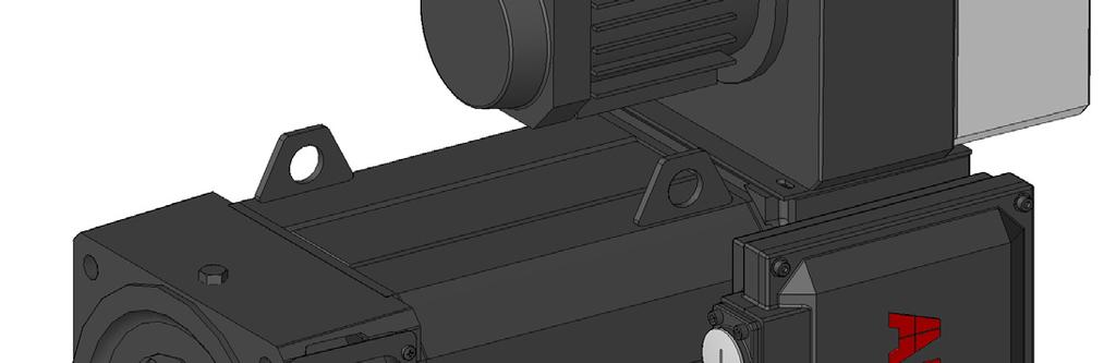
33 Chapter 3 Mechanical Installation Introduction This chapter provides information on mechanical installation of the HDP Servomotors manufactured by ABB Sace S.p.A. Lifting the motor The servomotor should be lifted by a suitable crane from the lifting eyes located on the motor frame. Carefully place and mount the servomotor on the machine. During this procedure avoid collision with any other equipment or damaging of any part of the motor. Finish installation: fix the motor to the mounting flange or foundation, and couple to the load. Note. Proper mechanical installation includes correct alignment between motor and load to avoid vibrations and consequently shaft, bearing failures. Manual for High Dynamic Performance AC Induction Servomotors - MANUM5.711 E 33
34 Chapter 3 Mechanical Installation Usage notes A particular care from the mechanical point of view must be devoted when using any kind of servomotor. Since the most delicate part of a servomotor are bearings and shaft, information on mounting constraints and on the usage of the coupling of the motor to its load through the DE shaft will be in particular given. On the other hand, for what concerns mounting of the motor to the mechanical body of the machine there are not particular instructions or recommendations, but the normal professional competence of the installer. Bearings Standard HDP Servomotors are provided with double metallic shield, type ZZ-C3, permanently greased, rolling ball bearings. These bearings allow radial loads: axial forces should be avoided since they heavily reduce the ball bearings lifetime. Though, simultaneous axial and radial forces are permissible and can be evaluated. If heavy radial stresses are foreseen, the servomotor can be provided with roller bearing on the DE-side, or with various types of reinforced bearings. These are optional arrangements that must be specified at ordering time. The documentation below gives an overview for estimating the loads that can be acting on the motor-shaft, and a table of the possible arrangements for the best use of HDP Servomotors. Bearing Options The following table lists possible bearing options suitable for HDP Servomotors in case of heavy loads applications. Motor Type Standard Ball Bearings Roller Bearing Reinforced Roller Bearing Reinforced Ball Bearings Double Shaft Value POS CH [H1 - IP54] DE 638 NU38 NE CM [H132 - IP54] DE 631 NU NE CN [H16 - IP54] DE 6312 NU312 NU NE CR [H2 - IP54] DE 6314 NU315 NU NE VH [H1 - IP23] DE 638 NU NE VM [H132 - IP23] DE 631 NU NE VN [H16 - IP23] DE 6312 NU312 NU NE VR [H2 - IP23] DE 6314 NU315 NU NE Manual for High Dynamic Performance AC Induction Servomotors - MANUM5.711 E
35 Chapter 3 Mechanical Installation Bearing Endurance After a certain period of continuous operation, rolling bearings properly mounted and used start revealing signs of deterioration, until component failure. Bearings have then their lifetime, depending on the time of operation, the load and working conditions, and the shaft rotation speed. Deterioration symptoms are abnormal noiseness and high temperature, or vibrations during operation. The application, the loads, and the overall working conditions of the servomotor, must therefore be optimized in order to extend the average lifetime of the bearings. Note. The estimation of loads acting on the motor shaft and, hence, the bearings endurance is fully under care and responsibility of the user and manufacturer of the final application. Fault bearings can be safely replaced, as ordinary maintenance in the factory. Please contact ABB Sace - Line S, Customer Service, for repairing service. Loads acting on DEshaft In the standard configuration, the locked bearing is mounted on the motor shaft-end side. The figure shows schematically the loads that can be acting on the shaft. F R z F A where: F R = Radial load [N] F A = Axial load [N] z = distance between centers of DE bearing and pulley Manual for High Dynamic Performance AC Induction Servomotors - MANUM5.711 E 35
36 Chapter 3 Mechanical Installation Bearing lifetime calculation Radial loads occur on the shaft DE when a pulley is applied to it. In this case, the following formula can be used to calculate the radial force acting on the DE bearing: F R = 19,5 1 6 Pn K n D where: F R = Radial load [N] P n = Rated motor power [kw] n = rated motor speed [RPM] D = external pulley diameter [mm] K = coefficient depending on belt type K = 1.2 (cogged belt) K = 2.3 (V-belt) K = 3.8 (flat belt) When axial and radial forces are know, the basic rating life of the DE bearing can be estimated in hours as follows: Cr Lh = for ball bearings 6 n P where Cr Lh = for roller bearings 6 n P - n : motor rated speed or rated speed of the application - Cr : basic dynamic load rating of the bearing - P : dynamic equivalent load ( XF r + YF a ) acting on the bearing. Note. F R and F A are the known axial and radial load, respectively, acting on the motor shaft (see figure above). F r and F a are axial and radial reaction forces of the bearing: these dynamic forces can be obtained by the moment balance (see figure and example below). 36 Manual for High Dynamic Performance AC Induction Servomotors - MANUM5.711 E
37 Chapter 3 Mechanical Installation Example. Calculation of the basic rating life of DE bearing, type 631, of HDP Servomotors type CM3.7 assuming that a radial load F R = 23N and axial load F A = 1N are applied to the motor shaft at a rated speed of 4 rpm, in the condition of radial load at half shaft-end. F R F A F a F r When calculating the dynamic reactions F a and F r of the DE bearing, the following technical specification of the manufacturer are necessary. Bearing Type C r [N] C or [N] f , , , , , , , ,2 Dynamic Equivalent Load P = XF r + YF a F a F f a F a e > e e F r F C r or X Y X Y,172,19 1,56 2,3,345,22 1,56 1,99,689,26 1,56 1,71 1,3,28 1,56 1,55 1,38,3 1,56 1,45 2,7,34 1,56 1,31 3,45,38 1,56 1,15 5,17,42 1,56 1,4 6,89,44 1,56 1, The dynamic radial and axial loads acting on the DE bearing in IM B3-B5-B35 mounting can be calculated as follows: F a = F A Fp = 5N F r a+ b+ c = F R b+ c = 3117N (see next table of motor parameters a, Obtain the values: b + c, F p ) f F a C or =,194 by which minimum e =, 19 and F a F r =, 1973 > e the resulting radial and axial load factor are X =,56 and Y = 2,26 (by linear interpolation); hence: P = XF r + YFa =, ,26 1 = 2885 N and the bearing lifetime results : L h C 1 62 = r = 6 n P = hours Manual for High Dynamic Performance AC Induction Servomotors - MANUM5.711 E 37
38 Chapter 3 Mechanical Installation The table below shows the motor data for bearing lifetime calculation. Motor type Distance between centers of DE bearing and pulley a Distance between centers of DE-NDE bearings Internal parameter b + c F p H1 - IP54 H132 - IP54 H16 - IP54 H2 - IP54 H1 - IP23 H132 - IP23 H16 - IP23 H2 - IP23 CH ,5 372 CH ,5 372 CH ,5 372 CH ,5 372 CH ,5 372 CH ,5 372 CM CM CM CM CM CN1 9, CN2 9, CN3 9, CN4 9, CN5 9, CR1 17,5 497,5 114 CR2 17,5 537,5 114 CR3 17,5 587,5 114 CR4 17,5 657,5 114 CR5 17,5 757,5 114 VH VH VH VH VH VH VM VM VM VM VM VN1 9,5 415,5 586 VN2 9,5 465,5 586 VN3 9,5 525,5 586 VN4 9,5 585,5 586 VN5 9,5 645,5 586 VR1 17, VR2 17, VR3 17, VR4 17, VR5 17, Manual for High Dynamic Performance AC Induction Servomotors - MANUM5.711 E

39 Chapter 3 Mechanical Installation Roller Bearings HDP Servomotors provided with a roller bearing on the DE side and a ball bearing on the NDE side are designed to bear heavy radial torque applied to the motor shaft. Running the motor with axial force applied to the shaft will damage the roller bearing. The roller bearings are greased in the factory with grease type: SKF LGHQ 3/1 LGHQ 3/1 is lithium soap-mineral grease for high-temperature applications. Even if high-quality grease is used, there is deterioration of its properties with time; therefore periodic regreasing is required. Motors equipped with roller bearings mount a grease cup on top of the motor front-flange for periodic regreasing. We advice to use the same factory grease LGHQ 3/1 or of equivalent properties. Regreasing time intervals depend a lot on the motor duty, the motor speed, the ambient temperature and the load type. The regreasing intervals of the roller bearings can be estimated in duty hours by the following curves, assuming an ambient temperature of 2 C (bearing temperature ca. 7 C) and a load factor 1. Regreasing intervals in duty hours For a given shaft diameter d, a time interval (h) results for each motor speed (rpm). If the bearing temperature exceeds 7 C, the time interval must be reduced by half for every 15 C temperature rise. If a continuous duty at different speeds and/or different loads is foreseen, a calculation must be made to estimate the medium regreasing time intervals. Manual for High Dynamic Performance AC Induction Servomotors - MANUM5.711 E 39
40 Chapter 3 Mechanical Installation When special motors with reinforced bearings and/or additional equipment are used, contact ABB Sace. Even though roller bearings are used for extended radial loads, an axial force is permissible and can be estimated by the curves below according to the shaft diameter and the motor rotational speed. Permissible axial load on roller bearings Pulleys and couplings Couplings, sheaves and pinions must be assembled using adequate tools, absolutely avoiding the use of a hammer, which could cause serious damage to the motor. Once the assembly has been completed, the shaft should be greased in order to avoid oxidation. Mounting according to IMVx configuration In vertical mounting due to the different kind of mechanical loads, due to the vertical forces acting on the motor, it is necessary to consider the effect of these loads on the bearings life. In these cases ABB Sace recommends to contact the Customer Service. 4 Manual for High Dynamic Performance AC Induction Servomotors - MANUM5.711 E
41 Chapter 4 Electrical Installation Introduction This chapter contains the instructions for electrical installation of HDP induction servomotors manufactured by ABB Sace S.p.A. Safety WARNING! Electrical installation must be carried out only by skilled persons. Carefully observe the Safety Instructions given at the beginning of this Manual. Note. Electrical installation must be carried out observing the local standards as well. Electrical installation includes preparation and layout of the power and signal cables, insulation distances and requirements, earthing of the machine, compliance to EMC standards. WARNING! Switch off both power and auxiliary supply of the drive before any operation of electrical installation or maintenance. Manual for High Dynamic Performance AC Induction Servomotors - MANUM5.711 E 41
High Dynamic Performance AC Induction Servomotors. Technical Manual
 ABB Sace High Dynamic Performance AC Induction Servomotors Technical Manual High Dynamic Performance AC Induction Servomotors Technical Manual MANUM5.611 E EFFECTIVE: 2.11.26 SUPERSEDES: 26.1.26 26 ABB
ABB AC Brushless Servodrives ABB. AC Brushless Servomotors Series 9C Installation and Use. 9C Servomotors Manual
 ABB ABB AC Brushless Servodrives AC Brushless Servomotors Series 9C Installation and Use 9C Servomotors Manual AC Brushless Servomotors Series 9C 9C Servomotors Manual MANUM09 REV E EN EFFECTIVE: 15.03.2008
STAR ELECTRIC COMPANY
 STAR ELECTRIC COMPANY STECO manufacturers a complete range of Energy Efficient Mors conforming IS: 325. Efficiency class Improved efficiency PRODUCT RANGE International Standards 60034-1,5 60072 Rotating
MT MOTORI ELETTRICI. Installation, operation, maintenance and safety manual for motors used in hazardous areas 1-II-2G 21-II-2D
 MT MOTORI ELETTRICI Installation, operation, maintenance and safety manual for motors used in hazardous areas 1-II-2G 21-II-2D TABLE OF CONTENTS 1. Introduction 2. Scope of application 3. Installation
ESR. The Dynamic Solution. Applications. Products, Consultation, and Service. ESR Pollmeier GmbH
 Analog AC servo drive systems with sinusoidal commutation Servo drives in compact design, 230 V AC mains connection Servo motors with high power density up to 5.0 Nm / 1.1 kw Components of the TrioDrive
WATERFLUX 3000 Quick Start
 WATERFLUX 3000 Quick Start Electromagnetic flow sensor The documentation is only complete when used in combination with the relevant documentation for the signal converter. KROHNE CONTENTS WATERFLUX 3000
RDrive 85 servo motors. User manual
 INTRODUCTION Rozum Robotics has designed its RDrive (RD) servo motors to enable precision motion control in industrial and commercial applications. This manual is intended for technicians and engineers
Thermistor motor protection relays
 Thermistor motor protection relays Content Benefits and advantages... / 68 Selection table... / 68 Ordering details CM-MSE... / 69 CM-MSS... / 69 CM-MSN... / 7 PTC sensor C0... / 7 Technical data... /
WATERFLUX 3000 Quick Start
 WATERFLUX 3000 Quick Start Electromagnetic flowmeter The documentation is only complete when used in combination with the relevant documentation for the signal converter. KROHNE CONTENTS WATERFLUX 3000
WDBR Series (RoHS compliant)
") WDBR Series (RoHS compliant) This new range of thick film planar power resistors on steel, offering high pulse withstand capability, compact footprint and low profile, to many demanding applications including
WDBR Series (RoHS compliant) This new range of thick film planar power resistors on steel, offering high pulse withstand capability, compact footprint and low profile, to many demanding applications including
Lexium integrated drives
 Description ILp for CANopen, PROFIBUS DP, RS ILA with AC synchronous servo motor Description ILA comprise control electronics with a fieldbus interface for CANopen DS, PROFIBUS DP or RS and an AC synchronous
Instruction manual for STA 1 sectional door operator
 Instruction manual for STA 1 sectional door operator Sectional door operator STA 1 / Rev. 0.3 1 GB 1. Contents 3. General safety instructions 1. Contents 2 2. Key to symbols 2 3. General safety instructions
Compact drives. Rotary actuators
 Compact drives Rotary actuators Production and delivery of servodrives and control systems. The Czech company TG Drives offers servodrives since 1995 for machines and equipments in industrial automation.
Instruction manual for STA 1 sectional door operator
 Instruction manual for STA 1 sectional door operator GB Sectional door operator STA 1 / Rev. 0.0 1 1. Contents 3. General safety instructions 1. Contents 2 2. Key to symbols 2 3. General safety instructions
EC 45 flat with integrated electronics Document ID: en Operating Manual
 EC 45 flat with integrated electronics Document ID: 919801en Operating Manual Edition June 2017 The EC 45 flat with integrated electronics is a brushless, speed-controlled 1-quadrant drive. It is available
Product Information ECI 1319S EQI 1331S. Absolute Rotary Encoders without Integral Bearing and with DRIVE-CLiQ Interface.
 Product Information ECI 1319S EQI 1331S Absolute Rotary Encoders without Integral Bearing and with DRIVE-CLiQ Interface Firmware 15 12/2018 ECI 1319S, EQI 1331S Rotary encoders for absolute position values
TETRA COMPACT - E AND FLEXI - PRO
 TETRA COMPACT - E AND FLEXI - PRO THE ENHANCED SERVO BUNDLE Motor Power Company introduces its new brushless servo bundle: TETRA COMPACT- ENHANCED, brushless servomotors, perfectly matched with the FLEXI-PRO
ABB AC Brushless Servodrives Manual of the Safety Relay Board
 ABB Servomotors ABB AC Brushless Servodrives DGV 700 Converters for Speed, Torque and Positioning Control of Brushless AC Permanent Magnet Servomotors Manual of the Safety Relay Board ABB AC Brushless
ILA2E572PC1A0 integrated drive ILA with servo motor V - EtherCAT - indus connector
 Characteristics integrated drive ILA with servo motor - 24..48 V - EtherCAT - indus connector Main Range of product Product or component type Device short name Motor type Number of motor poles 6 Network
WDBR Series Application Note. Resistors. BI Technologies IRC Welwyn
 WDBR Series Resistors Background Information The WDBR range of thick film planar power resistors on steel, offers high pulse withstand capability, compact footprint and low profile, to many demanding applications
Incremental encoders Redundant sensing, isolated blind hollow shaft ø mm, cone shaft ø17 mm pulses per revolution
 Features Robust, compact housing Two bearings with large distance, one at each end High shaft load up to 450 N Shock resistant up to 250 g Shaft insulation up to 2.8 kv Highest operating speed 10000 rpm
Thermistor motor protection relays
 Thermistor motor protection relays Content Benefits and advantages... / 68 Selection table... / 68 Ordering details CM-MSE... / 69 CM-MSS... / 69 CM-MSN... / 7 PTC sensor C0... / 7 Technical data... /
Dynamo Brushless DC Motor and GreenDriveTM Manual
 Dynamo Brushless DC Motor and GreenDriveTM Manual This manual was developed as a guide for use by FIRST Robotics Teams using Controller Part Number 840205-000 in conjunction with the Nidec Dynamo BLDC
Snap Action Switches Technical Guide
 These basic principles apply to all our precision switches. The specific characteristics of each model are given in more detail in the relevant production sections. Switch construction Single-pole changeover
RoHS. High shaft load capacity. Shock / vibration resistant
 Due to their sturdy bearing construction in Safety Lock Design, the Sendix 5000 and 5020 offer high resistance against vibration and installation errors. The rugged housing, high protection level of up
Rozum Robotics has designed its RDrive servo motors to enable precision motion control in industrial and commercial applications.
 INTRODUCTION Rozum Robotics has designed its RDrive servo motors to enable precision motion control in industrial and commercial applications. This manual is intended for technicians and engineers who
USER MANUAL. Maxwell Technologies BOOSTCAP Ultracapacitor Energy Storage Modules for Low Duty Cycle Applications
 USER MANUAL Maxwell Technologies BOOSTCAP Ultracapacitor Energy Storage Modules for Low Duty Cycle Applications Models: BMOD0125 P064 B02 BMOD0094 P075 B02 Document #1014204 Notice: The products described
Servomotors Order Catalogue. LSN - Servomotors with stall torque 0.26 to 60 Nm
 Servomotors Order Catalogue LSN - Servomotors with stall torque 0.26 to 60 Nm ID No. 0814.205B.0-00 Date: 01/2019 Public-Version Subject to technical change without notice. The content of our catalogue
PROXIMITY SENSOR TERMINOLOGY
 Never use this desk reference for installation or operation of equipment. Refer to manual for installation and operation instructions. The following descriptions refer to the European standard EN 60947-5-2.
/DSM 050 HIGH MOMENT OVERLOAD CAPACITY, HIGH CAPACITY OF THE INTEGRATED RADIAL-AXIAL OUTPUT BEARINGS, HIGH DYNAMIC PERFORMANCE.
 /DSM 050 The high precision DriveSpin DS 050 actuators represent the smallest serially produced member of the DriveSpin product range, meeting even the most demanding requirements of customers from all
TPM + power. Bosch Rexroth IndraDrive. Quick Startup Guide D Revision: 02
 4091-D021068 01 TPM + power Bosch Rexroth IndraDrive Quick Startup Guide 4091-D021074 Revision: 02 Quick Startup Guide TPM + power Revision history Revision Date Comment Chapter 01 08.07.2009 First release
847H. Description. Features. Specifications
 847H Bulletin 847H High Performance Industrial Incremental Encoders provide code disk resolutions of up to 65536 pulses per revolution at a signal frequency response of 820 khz. The 847H can provide 65536
SCREW JACKS Operating Instructions
 INS114EN.5 SCREW JACKS Operating Instructions Sweden Int +46 372 265 00 info@swedrive.se Vat.no SE556145631901 138-4551 1 Table of Contents 1. Health and Safety... 3 1.1. Notice about safety... 3 1.2.
Optical encoder MEC22 HR
 Optical encoder MEC22 HR Description The MEC22 HR is a high resolution optical hollow shaft encoder that can be fixed quickly and easily on different sizes of motor shafts. The encoder provides two square
Operating instructions for Motor grinding spindle HMS90X220F-HSK-C50/006
 STEINMETZ Schleiftechnik Postfach 51 D-63789 Karlstein / M Telefon 06188/7495 Telefax 06188/77570 E-Mail: info@steinmetz-schleiftechnik.de Internet: www.steinmetz-schleiftechnik.de Operating instructions
XXXX e. X d.. X X X a
 The Heavy Duty incremental encoder type 0H boasts a high degree of ruggedness in a very compact design. Its special construction makes it perfect for all applications in very harsh environments. / RoHS
TPM + Lenze ECS. Quick Startup Guide D Revision: 02
 4091-D012345 00 TPM + Lenze ECS Quick Startup Guide 4091-D032121 Revision: 02 Quick Startup Guide TPM + Revision history Revision Date Comment Chapter 01 27 th July 2012 First release All 02 27 th March
/DSM 070 HIGH MOMENT OVERLOAD CAPACITY, HIGH CAPACITY OF THE INTEGRATED RADIAL-AXIAL OUTPUT BEARINGS, HIGH DYNAMIC PERFORMANCE.
 /DSM 070 The high precision DriveSpin DS 070 actuators represent the medium-size serially produced member of the DriveSpin product range, meeting even the most demanding requirements of customers from
Order/Technical Support Tel: (800) / FAX: (800) /
 / FAX: (800) /") Key-operated safety interlock switch, plastic Without key locking Switches with plastic body for use on light machinery, without inertia. For use in unstable environments where there is a risk of the guard
Key-operated safety interlock switch, plastic Without key locking Switches with plastic body for use on light machinery, without inertia. For use in unstable environments where there is a risk of the guard
Contents. About the Authors. Abbreviations and Symbols
 About the Authors Preface Abbreviations and Symbols xi xiii xv 1 Principal Laws and Methods in Electrical Machine Design 1 1.1 Electromagnetic Principles 1 1.2 Numerical Solution 9 1.3 The Most Common
TECHNICAL DATA TYPE CMD OIL-IMMERSED ON-LOAD TAP CHANGER
 TECHNICAL DATA TYPE CMD OIL-IMMERSED ON-LOAD TAP CHANGER HM0.154.1901 SHANGHAI HUAMING POWER EQUIPMENT CO., LTD. General 1. General 3 2. Technical specifications 4 3. Type explanation 5 4. Terms and definitions
Position Transmitter TGS 40 (RAM)
") Operating Instructions 42/14-50 EN Position Transmitter TGS 40 (RAM) Position Transmitter TGS 40 (RAM) Operating Instructions Document no. 42/14-50 EN Date of issue: 05.2006 Revision: B Manufacturer: ABB
Operating Instructions 42/14-50 EN Position Transmitter TGS 40 (RAM) Position Transmitter TGS 40 (RAM) Operating Instructions Document no. 42/14-50 EN Date of issue: 05.2006 Revision: B Manufacturer: ABB
SGMMV. Rotary Servomotors SGMMV - A1 A 2 A 2 1. Model Designations. 6th. 5th digit. 1st+2nd digits. 7th digit. 4th digit. 3rd digit.
 Rotary s Model Designations - mini Series st+nd digits 3rd digit th digit th digit 6th digit 7th digit st+nd digits Rated Output th digit Design Revision Order 7th digit Options Code Code Code B3 3.3 W
Phone: Fax: Web: -
 ue to their sturdy bearing construction in Safety-ock esign, the Sendix 5000 and 500 offer high resistance against vibration and installation errors. The rugged housing, high protection level of up to
8902/RE and 8902/RR Resolver Speed Feedback Options
 8902/RE and 8902/RR Resolver Speed Feedback Options Technical Manual HA469251U002 Issue 1 Compatible with Version 2.x and 3.x Software Copyright 2009 Parker SSD Drives, a division of Parker Hannifin Ltd.
Incremental encoders Blind hollow shaft or cone shaft pulses per revolution
 Features TTL output driver for cable length up to 550 m Very high resistance to shock and vibrations Hybrid bearing for extended service life Shaft insulation up to.8 kv Large terminal box, turn by 80
High Frequency Sinewave Guardian TM Filter
 High Frequency Sinewave Guardian TM Filter 380V 480V TECHNICAL REFERENCE MANUAL FORM: SHF-TRM-E REL. April 2015 REV. 001 2015 MTE Corporation Caution Prior to start up; confirm the drive operation mode
STANDARD ELECTRIC LINEAR SERVOACTUATION PACKAGES
 STANDARD ELECTRIC LINEAR SERVOACTUATION PACKAGES SIZE 3, AND HIGH PERFORMANCE DESIGN INCREASES MACHINE PRODUCTIVITY; INTEGRATED SYSTEM INCREASES EASE OF INSTALLATION Rev. A 79 WHAT MOVES YOUR WORLD TABLE
LENORD. +BAUER... automates motion. GEL 2351 with current or voltage interface. Technical information Version General. Features.
 GEL 2351 with current or voltage interface LENORD +BAUER... automates motion. Technical information Version 201-11 General Single turn absolute rotary encoder with a resolution of 16 bits Magneto-resistive
AC SERVO DRIVES SERIES. Rotary Servomotors. Certified for ISO9001 and ISO14001
 C SERVO DRIVES SERIES Rotary Servomotors Certified for ISO91 and ISO141 JQ-422 JQ-EM22 CONTENTS Rotary Servomotors SGMMV (ow Inertia, Ultra-small Size) 4 SGM7J (Medium Inertia, High-speed) 14 SGM7 (ow
Motor makers gear up to provide the best servomotor for your application
 Motor makers gear up to provide the best servomotor for your application It s no longer necessary to pour over endless catalogs from multiple manufacturers looking for just the right servomotor to fit
Integrated servo motor
 R88E-AECT@, R88S-EAD@ Integrated servo motor Motor and drive integrated for space optimization Wide range of motors from 2.55 Nm to 25 Nm 3000 rpm rated speed Peak torque 300% of rated torque IP65 protection
Standard Sendix 5000 / 5020 (shaft / hollow shaft) Push-Pull / RS422 / Open collector. Robust performance. Many variants
 Push-Pull / RS422 / Open collector. Robust performance. Many variants") ue to their sturdy bearing construction in Safety-ock esign, the Sendix 5000 and 500 offer high resistance against vibration and installation errors. The rugged housing, high protection level of up to
ue to their sturdy bearing construction in Safety-ock esign, the Sendix 5000 and 500 offer high resistance against vibration and installation errors. The rugged housing, high protection level of up to
TETRA COMPACT LOW VOLTAGE BRUSHLESS SERVOMOTORS
 TETRA COMPACT LOW VOLTAGE BRUSHLESS SERVOMOTORS BRUSHLESS TECHNOLOGY FEATURES AND BENEFITS Synchronous brushless servomotor, permanently excited Rated output power from 60W to 800W Maximum servomotor speed
Proximity Sensor Terminology
 The following descriptions refer to the European standard EN 60947-5-2. of 2007. The specifications given here are intended to be minimum performance values described by the standard. Alignment must not
Magnetic absolute encoder GEL 2035 Serial interface (SSI), 24 Bit
, 24 Bit") Magnetic absolute encoder GEL 2035 Serial interface (SSI), 24 Bit Technical information Version 03.09 Resolution: Precision: 0.8 Signal pattern: Singleturn (ST): Multiturn (MT): up to 24 Bit SSI and SSI
Magnetic absolute encoder GEL 2035 Serial interface (SSI), 24 Bit Technical information Version 03.09 Resolution: Precision: 0.8 Signal pattern: Singleturn (ST): Multiturn (MT): up to 24 Bit SSI and SSI
ACTIVE and ACTIVE Cube. Installation manual - Cold Plate Frequency Inverter 230V / 400V
 ACTIVE and ACTIVE Cube Installation manual - Cold Plate Frequency Inverter 230V / 400V General points on the documentation This documentation is valid for the frequency inverter series ACT and ACU in
Overtravel of 3.5 mm max. Power source DC D5C-1DS0 D5C-1DP0 D5C-1DA0 AC D5C-1AS0 D5C-1AP0 D5C-1AA0 Antenna only D5C-00S0 D5C-00P0 D5C-00A0
 Touch Switch Unique 18 mm Capacitive Touch Switch with Choice of Three Actuators is Activated with Only a Very Slight Physical Contact Lightweight objects, such as thin wire or foil can be accurately detected.
Trunnion bearing housings for grinding mills FSDR.. K series
 Trunnion bearing housings for grinding mills FSDR.. K series Bearing types Spherical roller bearings Bearing dimension series 39, 48 and 49 Shaft diameter range 825 to 1 460 mm Typical bearing-shaft combinations
Servodrives. TGN servomotors AKD digital servoamplifiers
 Servodrives TGN servomotors AKD digital servoamplifiers Production and delivery of servodrives and control systems. The Czech company TG Drives offers servodrives since 1995 for machines and equipments
Rotary Position Technology Incremental Encoders
 -40 to 80 C Temperature Shock/vibration resistant Short-circuit protected Reverse polarity protection High rotational speed Rugged Balanced, stainless-steel clamping rings, special bearing-shaft connection
LENORD. +BAUER... automates motion. Magnetic incremental encoder GEL 293 for heavy duty applications. Technical Information Version 04.
 Magnetic incremental encoder GEL 293 for heavy duty applications LENORD +BAUER... automates motion. Technical Information Version 04.14 General information High-resolution magnetic incremental rotary encoder
ATS22C21Q soft starter-ats22-control 220V-power 230V(55kW)/ V(110kW)
/ V(110kW)") Characteristics soft starter-ats22-control 220V-power 230V(55kW)/400...440V(110kW) Product availability : Non-Stock - Not normally stocked in distribution facility Price* : 2383.00 USD Main Range of product
Characteristics soft starter-ats22-control 220V-power 230V(55kW)/400...440V(110kW) Product availability : Non-Stock - Not normally stocked in distribution facility Price* : 2383.00 USD Main Range of product
ROUND BENDING MACHINE Model: RBM30
 ROUND BENDING MACHINE Model: RBM30 Operation Manual SAVE THIS MANUAL:You will need the manual for the safety warnings and precautions, assembly instructions, operating and maintenance procedures, parts
maxon document number:
 maxon document number: 791272-04 1 Table of contents... 2 2 Table of figures... 3 3 Introduction... 4 4 How to use this guide... 4 5 Safety Instructions... 5 6 Performance Data... 6 6.1 Motor data... 6
Magnetic Encoder MEM 22
 Description The MEM 22 is a magnetic incremental encoder. He is a reliable low cost hollow shaft encoder that can be fixed quickly and easily on different sizes of motor shafts. The encoder MEM22 is designed
Installation and Operational Instructions for ROBA -switch Type 017._00.2
 OBA -switch Type 017._00.2 Guidelines on the Declaration of Conformity A conformity evaluation has been carried out for the product in terms of the EC Low Voltage Directive 2014/35/ EC and the EMC Directive
XXXX e. X d.. X X X a
 The Heavy uty incremental encoder type 0H boasts a high degree of ruggedness in a very compact design. Its special construction makes it perfect for all applications in very harsh environments. / RoHS
T10FS. Data Sheet. Torque Flange. Special features. Installation example T10FS. B en
 T10FS Torque Flange Data Sheet Special features Nominal (rated) torques: 100 NVm, 200 NVm, 500 NVm, 1 knvm, 2 knvm, 3 knvm, 5 knvm, 10 knvm Nominal speed from 12,000 rpm to 24,000 rpm Low rotor weights
Stepper Motors WE CREATE MOTION
 WE CREATE MOTIO PRECIstep Technology EW Page FDM 6 Two Phase with Disc Magnet, AM 8 Two Phase,6 AM Two Phase,6 ADM S Two Phase with Disc Magnet, 6 7 AM Two Phase 6 8 AM Two Phase AM -R Two Phase WE CREATE
SD Series. AC Spindle Motor Drives with Power Regeneration, AC Servo Drives. Speed Reference with Analog Voltage Expanded Functions
 AC Spindle Motor Drives with Power Regeneration, AC Servo Drives SD Series Speed Reference with Analog Voltage Expanded Functions Power Regeneration Converter Model CACP-JU SERVOPACK Model CACR-JU Spindle
AC Drive Technology. An Overview for the Converting Industry. Siemens Industry, Inc All rights reserved.
 AC Drive Technology An Overview for the Converting Industry www.usa.siemens.com/converting Siemens Industry, Inc. 2016 All rights reserved. Answers for industry. AC Drive Technology Drive Systems AC Motors
Product Information. EQN 1337 F Absolute Rotary Encoder with Tapered Shaft for Fanuc Controls with i Interface
 Product Information EQN 1337 F Absolute Rotary Encoder with Tapered Shaft for Fanuc Controls with i Interface 11/2017 EQN 1337 F Rotary encoders for absolute position values Installation diameter 65 mm
PARTNER ALTERNATORS LSA 40-4 Pole
 23 kva - 50 Hz 12,5 28 kva - 60 Hz 4250 en - 2011.03 / c PARTNER ALTERNATORS LSA 40-4 Pole Electrical and mechanical data SPECIALLY ADAPTED TO APPLICATIONS The LSA 40 alternator is designed to be suitable
InTurn Ultra and Ultra-T Indexing and Turning 4 th axis
 Specifications for the InTurn Ultra and Ultra-T Indexing and Turning 4 th axis Industrial quality. 100% duty cycle. Production ready. The InTurn series is the only CNC mill accessory that provides both
Committed to Premium Quality. AC Servo System Catalog
 Committed to Premium Quality AC Servo System Catalog Company Profile CONTENTS DB100 Series AC Servo System 03 Application fields 04 Servo Driver Product Description 05 Servo Motor Product Description 07
Intrinsically safe pressure transmitter MBS 4201, MBS 4251, MBS 4701 and MBS 4751
 Data sheet Intrinsically safe pressure transmitter MBS 420, MBS 425, MBS 470 and MBS 475 The intrinsically safe pressure transmitter program is designed for use in hazardous environments and offers a reliable
Rotary Measurement Technology Absolute Encoders, Multiturn
 Mechanical drive Safety-LockTM High rotational speed -40 to 90 C IP Temperature High IP High shaft load capacity Shock/ vibration resistant Magnetic field proof Short-circuit proof Reverse polarity protection
Product Information. AK ERM 2xx0 TTR ERM 2x00 Modular Angle Encoders with Magnetic Scanning and Mechanical Fault Exclusion
 Product Information AK ERM 2xx0 TTR ERM 2x00 Modular Angle Encoders with Magnetic Scanning and Mechanical Fault Exclusion February 2017 ERM 2200 series Consisting of AK ERM 2280 and TTR ERM 2200 or TTR
Rotron ½ AXIMAX 1 Small Vaneaxial Fans
 Rotron ½ AXIMAX Small Vaneaxial Fans General Small Vaneaxial Information Small Vaneaxial Fans are compact, high-speed fans whose airflow is parallel to the motor shaft. The impeller and guide vanes are
SIMEAS-T. Operating Instructions Transducer without auxiliary power. 7KG6111 and 7KG6101. Operating Instructions
 Operating Instructions SIMEAS-T s Operating Instructions Transducer without auxiliary power for alternating current for alternating voltage for alternating voltage with expanded end range 7KG6111 and 7KG6101
Product Information. RCN 2000 RCN 5000 RCN 8000 Absolute Angle Encoders for Safety-Related Applications
 Product Information RCN 2000 RCN 5000 RCN 8000 Absolute Angle Encoders for Safety-Related Applications September 2013 RCN 2000 series Absolute angle encoders for safety-related applications Safe absolute
Protection components
 General Application LT3-Si thermistor protection units continuously monitor the temperature of the machines to be protected (motors, generators, etc.) by means of PTC thermistor probes embedded in the
Split case double suction centrifugal pump. Technical data Serie: DPAS C
 Split case double suction centrifugal pump Technical data Serie: DPAS C Table of Contents 1 Introduction 1.1 Fields of Application... 1. Pumped Liquids... 1.3 Design... 1. Bearings... 1.5 Shaft Seal...
UPA 150C. 50 Hz. Applications. Submersible Borehole Pumps for Well Diameters of 150 mm (6 inches) Operating Data. Design. Designation (Example)
 Operating Data. Design. Designation (Example)") Type Series Booklet 3400.52/4 -- 10 Applications Suitable for handling clean or slightly contaminated water in applications such as: -- domestic water supply -- general water supply -- irrigation and spray
Type Series Booklet 3400.52/4 -- 10 Applications Suitable for handling clean or slightly contaminated water in applications such as: -- domestic water supply -- general water supply -- irrigation and spray
USER MANUAL. Maxwell Technologies Ultracapacitor Energy Storage Modules. Models: BMOD0058 E016 B02 BMOD0006 E160 B02. Document
 USER MANUAL Maxwell Technologies Ultracapacitor Energy Storage Modules Models: BMOD0058 E016 B02 BMOD0006 E160 B02 Document 3000200.1 Notice: The products described herein are covered by one or more of
TECHNICAL SPECIFICATION
 TECHNICAL SPECIFICATION Bed type milling machine FS(Q) 100/125 INTELLECTUAL PROPERRY OF TOS KUŘIM - OS, a.s. page: 1 from 14 Article 1. GENERAL CHARACTERISTICS OF THE MILLING MACHINE 3 2. MACHINE DESCRIPTION
TRD-N/NH Series Incremental Encoders
 /N Series Encoders TRD-K TRD-K A TRD-GK TRD-J /N TRD-2E TRD-S/S Features Shaft and ollow Shaft type are available. Compact body with 5mm diameter and 35mm depth. Wide range of resolution from 1 to 2,5P/R.
Absolute Encoders Multiturn
 Absolute Encoders Multiturn Functional Safety, optical The absolute multiturn encoders Sendix 5863 SIL and 5883 SIL are perfectly suited for use in safety-related applications up to SIL3 according to DIN
Rotary Measurement Technology Incremental Encoders
 -20 to 60 C Temperature Shock/vibration resistant Short-circuit protection Reverse polarity protection High rotational speed Rugged Balanced, stainless-steel clamping rings, special bearing-shaft connection
MH3. Servo motor Motor manual V1.00, , V1.00,
 MH3 Servo motor Motor manual V1.00, 07.2014 www.schneider-electric.com The information provided in this documentation contains general descriptions and/or technical characteristics of the performance of
Ametek, Inc. Rotron Technical Products Division. 100 East Erie St., Suite 200 Kent, Ohio User's Guide. Number Revision F
 Ametek, Inc. Rotron Technical Products Division 100 East Erie St., Suite 200 Kent, Ohio 44240 User's 120 Volt, 800 Watt and 240 Volt, 1200 Watt Brushless Motor Drive Electronics 5.7" (145 mm) and 7.2"
Absolute Encoders - Singleturn
 The Sendix 5853 and Sendix 5873 singleturn encoders with SSI or BiSS interface and optical sensor technology can achieve a resolution of max. 7 bits. These encoders are also available with an optional
Side. Channel Blower APEX DARGANG MACHINERY CORPORATION
 Side Channel Blower APEX DARGANG MACHINERY CORPORATION Side Channel Blower Construction External bearing Cool-running Long life Motor Industrial quality /60Hz Squired-cage motor totally enclosed(ip55 )
HD25. Industrial Rugged Metal Optical Encoder Page 1 of 6. Description. Mechanical Drawing. Features
 Description HD25 Page 1 of 6 The HD25 is a rugged optical incremental shaft encoder designed for heavy-duty industrial applications. The housing, machined from a solid billet aluminum block and finished
External brake resistor AX2090-BW5x
 Documentation External brake resistor AX2090-BW5x Accessories for Beckhoff servo drive AX5000 Version: Date: 1.3 2018-03-14 Table of content Table of content 1 Foreword... 5 1.1 Notes on the documentation...
High Frequency SineWave Guardian TM Filter
 High Frequency SineWave Guardian TM Filter 380V 480V TECHNICAL REFERENCE MANUAL WARNING High Voltage! Only a qualified electrician can carry out the electrical installation of this filter. Quick Reference
Installation and Operational Instructions for ROBA -multiswitch Type 019._00.2
 Guidelines on the Declaration of Conformity A conformity evaluation has been carried out for the product in terms of the EU Low Voltage Directive 2014/35/ EU and the Electromagnetic Compatibility (EMC)
ELECTRONIC ROTARY GEAR MOTOR SERIES SED (AR2...SE )
") ELECTRIC ROTARY GEAR MOTOR SERIES SED (AR2...SE ) INSTALLATI AND OPERATING INSTRUCTIS 1 GENERAL FEATURES 2 2 TECHNICAL DATA 3 3 INSTALLATI 3 ELECTRIC CNECTIS 5 CALIBRATI 5 5.1 ENDSWITCHES 5 5.2 AUXILIARY
ELECTRIC ROTARY GEAR MOTOR SERIES SED (AR2...SE ) INSTALLATI AND OPERATING INSTRUCTIS 1 GENERAL FEATURES 2 2 TECHNICAL DATA 3 3 INSTALLATI 3 ELECTRIC CNECTIS 5 CALIBRATI 5 5.1 ENDSWITCHES 5 5.2 AUXILIARY
SNOE 200 SNR bearing housings
 Assembly, servicing and maintenance instructions SNOE 200 SNR bearing housings N TS5142 www.ntn-snr.com With You Contents 1. Types of housing with oil-lubricated pillow block 2. Preparation for assembly