Trunnion bearing housings for grinding mills FSDR.. K series
|
|
|
- Muriel Bradford
- 6 years ago
- Views:
Transcription
1
2 Trunnion bearing housings for grinding mills FSDR.. K series Bearing types Spherical roller bearings Bearing dimension series 39, 48 and 49 Shaft diameter range 825 to mm Typical bearing-shaft combinations Stepped shaft with bearing on an unthreaded sleeve FSDR.. K housings are large low-weight plummer (pillow) block housings designed specifically for grinding mills. They operate under arduous conditions in highly contaminated environments. With their highly effective sealing solution, they enable the incorporated bearing to achieve maximum service life by preventing the ingress of contaminants and enabling easy access for inspection and maintenance when necessary. Seals Labyrinth, V-ring, PTFE strip Lubrication Grease Materials Grey cast iron Spheroidal graphite cast iron Mounting Four-bolt mounting Compliance to standards Not standardized
3 Trunnion bearing housings for grinding mills FSDR.. K series Designations Standard housing design Features and benefits Housing material Paint, corrosion protection Dimension standards Product tables 15.1 FSDR.. K grinding mill housings Housing variants Sealing solutions Design considerations Typical shaft-bearing combinations Locating and non-locating bearing positions Load carrying ability Operating temperature Operating speed Shaft specifications Attachment bolt recommendations Lubrication Initial grease fill Relubrication Mounting Torque specifications Ventilation valves Eye bolts and lifting holes Supporting the housing Condition monitoring Accessories Ordering information
4 Designations Designation system for FSDR.. K trunnion bearing housings FSDR_ 39/1060 K/P45 Series FSDR Trunnion bearing housings for grinding mills Material Grey cast iron D Spheroidal graphite cast iron Size identification../.. Bearing dimension series / bearing bore diameter [mm] Suffixes 1) Housing with metric threads and G threads for grease fittings K Housing for bearings with a tapered bore on a split unthreaded sleeve on stepped shafts N9 Housing with inch threads and NPTF threads for grease fittings /P Painting variant according to customer specification (P01 to P999) 1) When multiple suffixes are used, they are listed in the same order as they appear here. Designation system for V-ring seals 1280 VRME R Size identification Diameter of the V-ring seal Design VRME V-ring seal with longer lip to allow larger axial movements Material R Acrylonitrile-butadiene rubber (NBR)
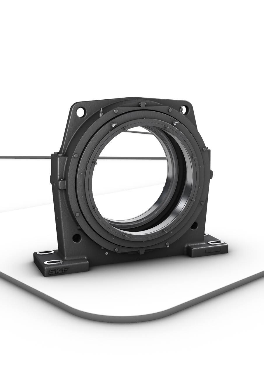
5 Trunnion bearing housings for grinding mills Standard housing design FSDR.. K plummer (pillow) block housings are split housings consisting of a cap and base, and two covers ( fig. 1). The cap has two integral flanges, with a hole cast into each one. The base has four cast holes for attachment bolts. The split covers, which contain an eye bolt in each half, are attached to the housing body with eight bolts. The labyrinth rings are supplied with eye bolts that can be removed after mounting. Features and benefits FSDR.. K housings have the following features and benefits: Superior sealing solution The SKF multi-stage labyrinth seal, which is standard for all trunnion bearing housings, is a highly effective sealing solution that can prevent the ingress of contaminants even during high-pressure wash downs. The inclined outside face of the labyrinth ring helps to prevent water and contaminants from entering the labyrinth ( fig. 2). Fig
6 Standard housing design Reduced grease consumption Trunnion bearing housings typically require large amounts of grease at frequent intervals, to purge contaminants from the bearing and housing. With SKF grinding mill housings however, the highly effective multi-stage labyrinth seal makes it possible to extend relubrication intervals, helps to eliminate overgreasing and reduce grease consumption. Easy access for inspection and maintenance The covers and labyrinth rings are split for easy removal. This enables the housing, bearing and seals to be inspected, or replaced, and used grease to be removed, without dismounting the housing. Machined base ends The base ends of FSDR.. K housings are machined to make alignment easier and to provide a flat surface for stops ( fig. 3). Ventilating valves Ventilating valves are supplied with the housing ( fig. 4). They help to prevent high pressures, which can be caused by heat, from building up in the housing. The valves have a 2 µm dirt filter. Sealing solution with one V-ring seal Inclined outside face Machined base ends Fig. 2 Fig. 3 Fig
7 Trunnion bearing housings for grinding mills Housing material FSDR.. K housings are made of grey cast iron. Paint, corrosion protection FSDR.. K housings are painted black (RAL 9005) using a solvent based acryl paint. The paint protects the housing in accordance with ISO , corrosivity category C2 (i.e. exterior atmospheres with low level of pollution, interior atmospheres where condensation may occur). The paint is not affected by most lubricating or engine oils, cutting fluids or alkalescent washing chemicals. Housings can be repainted with most water or solvent based 1- or 2-component paints. Unpainted surfaces are protected with a solventless rust inhibitor. Dimension standards The boundary dimensions of FSDR.. K housings are not standardized either nationally or internationally. Housing variants In addition to standard design FSDR.. K housings, a number of variants are also available. Housing material For applications where extra strength is needed, the housings are available in spheroidal graphite cast iron, designation FSDRD.. K. Inch thread connections FSDR.. K housings can be supplied with UNC or NPTF threads for grease fittings. The housings are identified by the designation suffix N9, e.g. FSDR 39/1060 KN9. For additional information, contact the SKF application engineer ing service. Special paint FSDR.. K housings can be supplied painted according to customer specification. The housings are identified by the designation suffix P, followed by a two or three-digit number, e.g. FSDR 39/1060 K/P
8 Sealing solutions Sealing solutions FSDR.. K housings are designed for two sealing solutions ( fig. 5): NOTE: V-ring seals and band clamps must be ordered separately. Appropriate V-ring seals and band clamps are listed in table 2, page 647. a labyrinth seal in combination with one V-ring seal and a PTFE strip, for all housings except size 49/1320 a labyrinth seal in combination with two V-ring seals, for housings size 49/1320 Table 1, page 646, provides an overview of the characteristics and suitability of both sealing solutions. Additional information is provided in the following text. This information should be used as a guideline, which cannot substitute for testing a seal in its application. The labyrinth seal consists of two parts: the housing cover and a labyrinth ring. Both are split. The cover is bolted to the housing body and does not rotate. The labyrinth ring is bolted onto a shaft sleeve and rotates with the shaft. The V-ring seals have a long seal lip that seals axially against the cover. They are located radially by steel clamping bands and axially by the labyrinth ring. For housings with one V-ring seal, a PTFE strip, mounted in a groove in the cover, provides additional protection. Labyrinth seals are supplied together with the housing, but can also be ordered separately. Contact SKF for additional information. Shaft sleeves are also supplied with the housing. Fig Labyrinth seal with one V-ring seal Labyrinth seal with two V-ring seals 645
9 Trunnion bearing housings for grinding mills Table 1 Seals for FSDR.. K trunnion bearing housings for grinding mills Seal Type labyrinth seal with 1 V-ring seal labyrinth seal with 2 V-ring seals Housing size range 39/850, 39/1060, 39/1180 and 48/ /1320 Material labyrinth seal grey cast iron grey cast iron V-ring seals rubber (NBR) rubber (NBR) PTFE strip PTFE impregnated fibres (ramie) n/a Application conditions and requirements Temperature [ C] 40 to to +100 Temperature [ F] 40 to to +210 Max. circumferential speed [m/s] 2 10 Max. misalignment [ ] 0,5 0,5 Low friction + ++ Axial shaft displacement [mm] ± 10 ± 10 Replacement Shaft tolerance class h9ve h9ve Shaft roughness R a [µm] 3,2 3,2 Sealing suitability Dust Fine particles Coarse particles Chips Liquids when sprayed Direct sunlight Symbol: n/a not applicable ++ very suitable + suitable limited suitability unsuitable 646
10 Sealing solutions Table 2 Clamping bands for V-ring seals Housing V-ring seal Clamping bands Size Designation Qty. Designation FSDR 39/850 K 960 VRME R 2 RM 15 Art. No Length RM 10 Art. No Length RM ADJUST Art. No Length 600 FSDR 39/1060 K 1180 VRME R 4 RM 15 Art. No Length RM ADJUST Art. No Length 700 FSDR 39/1180 K 1280 VRME R 4 RM 15 Art. No Length RM 10 Art. No Length 1000 FSDR 49/1320 K 1425 VRME R 12 RM 15 Art. No Length 1500 FSDR 48/1500 K 1575 VRME R 6 RM 15 Art. No Length RM ADJUST Art. No Length
11 Trunnion bearing housings for grinding mills Design considerations For general information about design considerations, refer to the following sections: Typical shaft-bearing combinations ( page 41) Locating/non-locating bearing systems ( page 40) Specifications for shafts and housing support surfaces ( page 45) Axial load carrying ability for bearings on a sleeve ( page 44) For additional information about rolling bearings, refer to the product information available online at skf.com/bearings. Typical shaft-bearing combinations FSDR.. K housings accommodate bearings with a tapered bore on an unthreaded sleeve on stepped shafts ( fig. 6). Locating and non-locating bearing positions FSDR.. K housings can be used for both the locating and non-locating bearing positions. Fig. 6 The housings are machined standard for bearings in the non-locating position. The bearing seat is sufficiently wide to allow axial displacement of the bearing. The seat tolerance provides a loose fit for the bearing even if there is a temperature difference between the bearing outer ring and housing. Bearings in the locating position must be secured in the housing on both sides with locating rings. These are supplied with the housings. Load carrying ability FSDR.. K housings are intended for loads acting perpendicularly toward the support surface as well as the forces created in the process. In cases like this, the housing can withstand the same loads as the bearing. If loads acting in other directions occur, contact the SKF application engineering service. Additional housing support As the housings are subjected to loads acting parallel to the support surface, a stop must be provided to counter the load. The housings can be secured to the support with keys or welded stops. The stop should be sufficiently strong to accommodate the loads acting parallel to the support surface. 648
12 Design considerations Operating temperature The permissible operating temperature is limited by the seals ( table 1, page 646). For temperature limits of SKF bearings and lubricants, refer to the product information available online at skf.com/bearings. The housing material does not have any additional temperature limits, except for very low temperatures where impact strength could be a factor. The housing paint is heat resistant up to 80 C (175 F) material temperature or 100 C (210 F) ambient temperature. When temperatures outside the permissible range are expected, contact the SKF application engineering service. Attachment bolt recommendations In typical applications, 8.8 class hexagon head bolts in accordance with ISO 4014 can be used together with washers in accordance with ISO 7089 or If the load does not act perpendicularly toward the base, it may be necessary to use stronger 10.9 class bolts. SKF housings can withstand loads resulting from tightening the attachment bolts to the torque values recommended by bolt manufacturers ( table 3). They are valid for oiled, but otherwise untreated, thread surfaces. SKF cannot guarantee that tightening to the recommended value provides sufficient anchoring. Make sure that attachment bolts, stops, and a sufficiently strong support can accommodate all occurring loads. Operating speed The seals limit the permissible operating speed. Speed limits for the seals are provided in table 1 on page 646. Shaft specifications The bearing seat should be machined according to the requirements for bearings mounted on an adapter sleeve ( Specifications for shafts and housing support surfaces, page 45), i.e. with a shaft tolerance class h9 VE and a cylindricity tolerance of IT5/2. The seal counterface should also comply with these specifications. Table 3 Torques values for cap bolts and attachment bolts Housing Cap bolts Attachment bolts Size Size Tightening Size Tightening torque torque 1) Nm Nm FSDR 39/850 K M M FSDR 39/1060 K M M FSDR 39/1180 K M M FSDR 49/1320 K M M FSDR 48/1500 K M M ) Recommended by bolt manufacturers. 649
13 Trunnion bearing housings for grinding mills Lubrication Fig. 7 FSDR.. K housings are intended for grease lubrication. The lubricant should be selected based on the operating conditions of the bearings. For additional information about lubricant selection, refer to the product information available online at skf.com/bearings. Initial grease fill If no other requirements exist, the free space in the bearing as well as the gaps of the labyrinth seals should be completely filled with grease. The seal counterfaces should be thoroughly greased. No extra grease is required for the housing. During start up, additional grease (typically 20 to 60 kg, depending on bearing size) should be added to the bearing over a 30-minute period via the annular groove and relubrication holes in the bearing outer ring. Detailed information about the initial grease fill is provided in the mounting instructions, which are available on request. 650
14 Lubrication Relubrication The spherical roller bearings used in FSDR.. K housings can be relubricated via two drilled and tapped G 3/8 holes in the housing base ( fig. 7). SKF recommends using an automatic lubrication system like the SKF MultiLube pumping unit ( Centralized lubrication systems, page 48). Relubrication instructions (which form part of the mounting instructions for the housings) are available on request. Fig. 8 Relubricating the labyrinth between the outer seal and cover (one V-ring) Relubricating the seals FSDR.. K housings with one V-ring per side have two drilled and tapped G 1/8 holes in the cover on each side of the housing. Grease introduced in either of the holes will relubricate both the V-ring and the labyrinth seal. Choose the hole that is most convenient ( fig. 8). FSDR.. K housings size 49/1320 with two V-rings per side have three drilled and tapped holes in the cover on each side of the housing. The hole that supplies grease to the space between the two V-rings has two alternative grease inlets (both G 3/8). Choose the one that is most convenient ( fig. 9). The single hole (G 1/8) supplies lubricant to the labyrinth seal ( fig. 10). Relubricating the space between two V-rings Fig. 9 Renewal Used grease should be replaced with fresh grease on a regular basis, typically every two to three years. Grease samples should be drawn and analyzed, and the interval adjusted accordiningly. To simplify the renewal process, the covers and labyrinth rings are split and can be removed without removing the cap. Fig. 10 Relubricating the labyrinth between the outer seal and cover (two V-rings)
15 Trunnion bearing housings for grinding mills Mounting FSDR.. K housings must be mounted properly using the appropriate tools and state of the art mechanical mounting methods. Mounting instructions for the housings are available on request. Torque specifications The M 24 cover bolts supplied with all housings should be tightened to 665 Nm. The cover bolts are in accordance with ISO The M 12 labyrinth ring bolts (in accordance with ISO 4017) supplied with the labyrinth seals should be tightened to 80 Nm. Cap bolts should be tightened to the torque values listed in table 3 on page 649. For information about attachment bolts, refer to Attachment bolt recommendations on page 649. Eye bolts and lifting holes FSDR.. K housings have a cast hole in each integral flange on the cap and one M16 eye bolt in each cover half ( fig. 11) for safe, easy handling. The labyrinth rings are equipped with adjustable eye bolts (VLBG 0.63t M 10 with bolt, except for size 49/1320, which has M10 eye bolts) that can be removed after mounting. Supporting the housing FSDR housings require two stops, one on each side of the housing, to accommodate loads acting parallel to the housing support surface. Ventilating valves The ventilating valves should be installed on top of the housing cap for use when the housing is in operation. The holes for the valves are plugged on delivery. Fig. 11 Eye bolts 652
16 Accessories Condition monitoring FSDR.. K grinding mill housings have seven drilled and tapped M8 holes for condition monitoring sensors ( fig. 12). Position 1 and position 2 (on both sides of the housing) are perpendicular to the shaft. Positions 3 and 4 (both positions available on both sides of the housing) are parallel to the shaft. All positions are in accordance with ISO Accessories The following accessories are available for FSDR.. K housings: Automatic lubricator: SKF MultiLube pumping unit Condition monitoring sensors For additional information, refer to the section SKF tools and products ( page 47). Fig. 12 Position 1 Position 2 15 Position 3 Position 4 653
17 Trunnion bearing housings for grinding mills Ordering information FSDR.. K housings are supplied with the following components: housing 2 covers, including O-rings and 8 hexagon head bolts per cover (16 in total) 2 labyrinth rings, including 10 hexagon head bolts per labyrinth ring (20 in total) 2 shaft sleeves, including O-rings 2 locating rings 2 ventilating valves 2 PTFE strips (for all housings except size 49/1320) The bearings, bearing sleeves, V-ring seals, and clamping bands must be ordered separately. Order example A trunnion bearing housing (with metric thread connections) is required for a 239/1060 CAK/W33 spherical roller bearing. The following items should be ordered: 1 housing FSDR 39/1060 K 1 bearing 239/1060 CAK/W33 1 bearing sleeve KOH 39/ V-ring seals 1180 VRME R 4 clamping bands RM 15 Art. No Length clamping bands RM ADJUST Art. No Length
18 Ordering information
19 15.1 FSDR.. K grinding mill housings d a mm A B s 1 B d B a B b B c D a d a d c H r 1 H 1 r 2 A 3 A 4 A 2 Shaft Housing Appropriate parts Dimensions diameter Designation Bearing Unthreaded sleeve V-ring seal Housing d a A A 1 A 2 A 3 A 4 mm mm 825 FSDR 39/850 K 239/850 CAK/W33 KOH 39/ VRME R 1) ,5 137, FSDR 39/1060 K 239/1060 CAKF/W33 KOH 39/ VRME R 1) ,5 172, FSDR 39/1180 K 239/1180 CAKF/W33 KOH 39/ VRME R 1) ,5 173, FSDR 49/1320 K 249/1320 CAK30F/W VRME R 2) FSDR 48/1500 K 248/1500 CAK30FA/W VRME R 1) ,5 1) Two seals are required for each housing. 2) Four seals are required for each housing. 656
20 G H 2 L 1 L J J 3 N 1 A 1 J 2 N J 1 Shaft Dimensions Dimensions Mass diameteing Housing Shaft abutment and fillet Hous- d a D a B H H 1 H 2 J J 1 J 2 J 3 L L 1 N N 1 s 1 G d c B 1) a B 1) b B c B 1) d r 1 r 2 mm mm kg , , , ) Dimension varies depending on the drive-up of the bearing onto the sleeve. 657
HMZ Locknuts simple and reliable locking devices
 simple and reliable locking devices Technical Product Information A Member of the Schaeffler Group Application Characteristics Application The new HMZ locknuts are easy to handle, permitting accurate and
Reinforced all-rubber HSS seals. Reliable protection for large size bearings
 Reinforced all-rubber HSS seals Reliable protection for large size bearings Reinforced all-rubber HSS seals The HSS seals are specially developed by SKF to protect large size bearings under the tough operating
Thread protection accessories are installed at the MODIX production factory and delivered with couplers.
 Installation of MODIX Rebar Coupler Identification of the product The type of MODIX Rebar Coupler can be identified by the marking on the product. Size of the Coupler can be identified also according to
Installation and Operational Instructions for ROBA -DS couplings Type 95. _ (disk pack HF) Sizes
 Sizes") 95. _ (disk pack HF) Sizes 6 22 Please read these Operational Instructions carefully and follow them accordingly! Ignoring these Instructions may lead to malfunctions or to coupling failure, resulting
95. _ (disk pack HF) Sizes 6 22 Please read these Operational Instructions carefully and follow them accordingly! Ignoring these Instructions may lead to malfunctions or to coupling failure, resulting
DODGE Grease Lubricated SPLIT-SPHER Roller Bearings and Pillow Blocks
 Mounting Instructions For DODGE Grease Lubricated SPLIT-SPHER Roller Bearings and Pillow Blocks WARNING: Because of the possible danger to person(s) or property from accidents which may result from the
Profile rail guides LLT. Mounting, maintenance and repair instructions
 Profile rail guides LLT Mounting, maintenance and repair instructions Contents 1 Profile rail guide system introduction.... 3 2 General instructions.... 4 2.1 Typical mounting examples.... 4 2.1.1 Rails...
4.4 PUMP MAINTENANCE MODELS: DB, DC, DF, DG, DJ, DL
 4.4 PUMP MAINTENANCE MODELS: DB, DC, DF, DG, DJ, DL 4.4.1 EXPLODED VIEW DRAWING REF. QTY. DB DC DF DG DJ DL DESCRIPTION PART # 1 1 ADAPTOR FRAME 034007 2 12 LOCK WASHER 3/8 x 1/8 S.S. 034004 3 12 HEX HEAD
Instruction Manual for DODGE SLEEVOIL RXT Pillow Blocks With External Circulating Oil Lubrication
 Instruction Manual for DODGE SLEEVOIL RXT Pillow Blocks With External Circulating Oil Lubrication These instructions must be read thoroughly before installation or operation. CAUTION: Do not scrape, rebabbit,
Mechanical Actuators
 Mechanical Actuators Rotating Machine Screw Actuators 2-Ton and Larger Capacity Installation, Operation & Maintenance Instructions Publication Part No. SK-2389-R CAUTION This manual contains important
DODGE Adapter Mounted DODGE USAF 500/600 Series Pillow Blocks
 DODGE Adapter Mounted DODGE USAF 500/600 Series Pillow Blocks These instructions must be read thoroughly before installation or operation. This instruction manual was accurate at the time of printing.
SNOE 200 SNR bearing housings
 Assembly, servicing and maintenance instructions SNOE 200 SNR bearing housings N TS5142 www.ntn-snr.com With You Contents 1. Types of housing with oil-lubricated pillow block 2. Preparation for assembly
PET*STAR 4 OPERATOR MANUAL
 Operator Manual 17315060 Rev. 0 (PS - 4) PET*STAR 4 OPERATOR MANUAL Paragraph Page 1.0 INTRODUCTION... 2 2.0 INSTALLATION... 2 3.0 ALIGNMENT... 2 4.0 SPHERICAL ROLLER BEARING & PILLOW BLOCK... 5 5.0 OUTBOARD
SPIETH Hydrodynamic Radial-Slide-Bearings
 SPIETH Hydrodynamic Radial-Slide-Bearings Series GLM Works Standard SN 03.01 2 Content Page 1. General 4 1.1. SPIETH Hydrodynamic Radial-Slide-Bearing 4 1.2. Hydrodynamic lubrication 4 1.3. Lubrication
Technical features. Positive Taper Lock System for manual tool clamping. Technical features:
 clamping set Technical features The RÖHM- was specially designed for the positive taper lock clamping taking particulary into account the necessity of manual clamping. Technical features: strong design
B-Too Drilling and Tapping Machine Instruction and Maintenance Manual
 B-Too Drilling and Tapping Machine Instruction and Maintenance Manual Thank you for your purchase of the B-Too Drilling and Tapping Machine. Please read and understand this short operation manual. Our
Technical Manual. ETP-CLASSIC incl type R. Content
 Technical Manual ETP-CLASSIC incl type R Content Technical parts description...2 Mounting/dismantling tips...4 Design suggestions...7 Tolerances...13 Central bolt...15 Torsional stiffness...16 Screw pitch
I-W07/W77. Couplings DETAIL A WARNING. Photo Showing Pipe with Weld Seam Ground 6 inches/152 mm Back from Pipe End and an AGS Groove
 WARNING Read and understand all instructions before attempting to install any Victaulic piping products. These products must be used only on pipe that is prepared to Victaulic Advanced Groove System (AGS)
PEDESTAL OVERHAUL. Some of the tools for a pedestal overhaul. Pedestal work stand
 INTRODUCTION A properly greased labyrinth seal will help prevent dust and water damage to the pedestal bearing oil supply and shaft seal area. Properly greased and oiled pedestals rarely require an overhaul.
HANDHOLE SEAT GRINDER
 1041-1601 HANDHOLE SEAT GRINDER OPERATING INSTRUCTIONS & SERVICE MANUAL Rev: A, 9/17/2007 TO REDUCE THE RISK OF INJURY AND EQUIPMENT DAMAGE USER MUST READ AND UNDERSTAND OPERATOR S MANUAL. Thomas C. Wilson,
Precision Double Row Cylindrical Roller Bearings With Tapered Bore
 Roller Bearings With Tapered Bore High precision cylindrical roller bearings are bearings with a low cross section, high load carrying capacity and speed capability. These properties make them particularly
Catalog October Speedi-Sleeve The quickest and most economical way to repair worn shafts
 Catalog 457027 October 2005 Speedi-Sleeve The quickest and most economical way to repair worn shafts Table of Contents The Speedi-Sleeve concept...3 SPEEDI-SLEEVE, the quickest and most sensible way to
4.2 - PUMP MAINTENANCE MODELS: AC, AS, WC, WS
 4.2 - PUMP MAINTENANCE MODELS: AC, AS, WC, WS 4.2.1 - EXPLODED VIEW DRAWING REF NO. 1 2 4 QTY 3 1 1.5 5 ¾ HP HP HP HP HP DESCRIPTION PART # 1 CASE 1.25 x 1 NPT 018266 1 CASE 1.25 X 1 NPT 018268 1 CASE
Instruction Manual for DODGE SLEEVOIL RXT Pillow Blocks With Self Lubrication (oil ring)
") Instruction Manual for DODGE SLEEVOIL RXT Pillow Blocks With Self Lubrication (oil ring) These instructions must be read thoroughly before installation or operation. CAUTION: Do not scrape, rebabbitt,
Instruction Manual for DODGE SLEEVOIL RXT Pillow Blocks With Self Lubrication (oil ring) These instructions must be read thoroughly before installation or operation. CAUTION: Do not scrape, rebabbitt,
Hardinge FlexC Dead-Length Collet System Style DL 42mm. Installation Instructions and Parts Lists
 Hardinge FlexC Dead-Length Collet System Style DL 42mm Installation Instructions and Parts Lists 1 General Safety Information Before installing the Hardinge FlexC Collet System on your machine tool, thoroughly
General Four-Way Operation, Maintenance & Service Manual
 General Four-Way Operation, Maintenance & Service Manual SCOPE Included in the following pages you will find assembly drawings, exploded views, parts lists, assembly tips, operational descriptions and
OPERATION AND MAINTENANCE INSTRUCTIONS AVK UNDERGROUND FIRE HYDRANT
 1. INTRODUCTION Operation and maintenance manual for the series underground CLEARWAY fire hydrant 1 of 7 The designs, materials and specifications shown are subject to change without notice due to our
Inventory MODEL T10096 TAPER ATTACHMENT FOR G0509 & G0509G LATHE INSTRUCTIONS. Inventory (Figure 1) Needed Items
 Needed Items") MODEL T10096 TAPER ATTACHMENT FOR G0509 & G0509G LATHE INSTRUCTIONS Inventory The Model T10096 taper attachment was carefully packed when it left our warehouse. If you discover it is damaged after you
MODEL T10096 TAPER ATTACHMENT FOR G0509 & G0509G LATHE INSTRUCTIONS Inventory The Model T10096 taper attachment was carefully packed when it left our warehouse. If you discover it is damaged after you
BEARING AND TYPES OF BEARING
 BEARING AND TYPES OF BEARING In this article, you will learn about bearing and types of bearing. Generally, all types of machinery are provided with supports for rotating shafts, the supporting device
Installation and Operational Instructions for ROBA -DX Couplings Type 931.3
 Please read these Operational Instructions carefully and follow them accordingly! Ignoring these Instructions may lead to malfunctions or to coupling failure, resulting in damage to other parts. Contents:
ROOP LAL Unit-6 Drilling & Boring Mechanical Engineering Department
 Lecture 4 Notes : Drilling Basic Mechanical Engineering ( Part B ) 1 Introduction: The process of drilling means making a hole in a solid metal piece by using a rotating tool called drill. In the olden
INSTRUCTIONS
 IMPORTANT: THIS IS A HIGH PERFORMANCE PART AND IMPROPER INSTALLATION COULD RESULT IN INJURY OR DEATH! NEVER WORK UNDER AN AUTOMOBILE THAT IS NOT PROPERLY SUPPORTED AND BLOCKED FROM ROLLING. NO CREDIT OR
Student, Department of Mechanical Engineering, Knowledge Institute of Technology, Salem, Tamilnadu (1,3)
") International Journal of Scientific & Engineering Research, Volume 7, Issue 5, May-2016 11 Combined Drilling and Tapping Machine by using Cone Mechanism N.VENKATESH 1, G.THULASIMANI 2, S.NAVEENKUMAR 3,
International Journal of Scientific & Engineering Research, Volume 7, Issue 5, May-2016 11 Combined Drilling and Tapping Machine by using Cone Mechanism N.VENKATESH 1, G.THULASIMANI 2, S.NAVEENKUMAR 3,
Technology Workpieces and processes in the automotive industry
 Technology Workpieces and processes in the automotive industry New machining solutions for that extra productivity and cost-effectiveness MAPAL technology: Tap the potential savings during the machining
Repair Manual MK40A-MK45A-MK50A MK55A-MK60A-MK65A. Ref Rev.C General Pump is a Member of The Interpump Group
 MK Repair Manual MK40A-MK45A-MK50A MK55A-MK60A-MK65A General Pump is a Member of The Interpump Group 8 INDEX 1. INTRODUCTION..................................................Page 3 2. REPAIR INSTRUCTIONS...........................................Page
Clamping devices 521
 Clamping devices 521 522 Product overview Clamping devices Adjustable straps K0001 Hook clamps K0012 Goose-neck straps with long slot K0002 Page 526 Hook Clamps with collar K0013 Page 535 Equipped clamps
w w w. h d o n l i n e s h o p. d e TIMKEN BEARING CONVERSION TOOL GENERAL INSTALLATION -J04672 REV Kit Number Models
 -J067 REV. 008-07- GENERAL Kit Number 8-08 Models TIMKEN BEARING CONVERSION TOOL For model fitment information, see the P&A Retail Catalog or the Parts and Accessories section of www.harley-davidson.com
Screws. Introduction. 1. Nuts, bolts and screws used to clamp things together. Screws are used for two purposes:
 Screws Introduction Screws are used for two purposes: 1. To clamp things together. 2. To control motion. 1. Nuts, bolts and screws used to clamp things together. Nuts, bolts and screws that are used for
Hardinge FlexC Dead-Length Collet System Style DL 80mm. Installation Instructions and Parts Lists
 Hardinge FlexC Dead-Length Collet System Style DL 80mm Installation Instructions and Parts Lists 1 General Safety Information Before installing the Hardinge FlexC Collet System on your machine tool, thoroughly
Top spin Nr /
 Top spin Nr. 1840 0000 / 1840 1000 Bedienungsanleitung 21-6680 28052014 / A Made in Germany Ideas for dental technology Top spin Nr. 1840 0000 / 1840 1000 Contents 1. Introduction...2 1.1 Symbols...2 2.
High Precision Air Chucks
 Precision Workholding Solutions High Precision Air Chucks www..com Improve productivity and lower the cost of secondary machining operations..... through high concentricity. Holding close concentricity
WHAT? WHERE? HOW?
 JIGS WHAT? WHERE? HOW? Introduction Mass production aims at high productivities to reduce unit cost and inter-changeabilites to facilitate easy assembly. Jigs are useful in mass production. They provide
1. TABLE OF CONTENT 2. ASSEMBLY ATEX. PENCOflex Installation Instructions & Service Manual
 ATEX 1. TABLE OF CONTENT 1. Table Of content... 1 2. Assembly... 1 3. Alignment... 2 4. Earthing... 3 5. Inspection and replacement of Elastic elements... 4 5.1. Rubber elements... 4 5.2. Pins... 4 5.2.1
SERVICE INSTRUCTIONS Model 9670 Lubricant Pump
 TM TM SERVICE INSTRUCTIONS Model 9670 Lubricant Pump 9670 DESCRIPTION Model 9670 Lubricant Pump is designed to pump light to heavy oils directly from the original container. This design features a 10:1
HC Hydraulic Expansion Chucks
 Technical Information HC Hydraulic Expansion Chucks design, function, effect, and application features, handling, and action application instructions precision tool length setting torques accessories sealed
INSPECTION AND CORRECTION OF BELLHOUSING TO CRANKSHAFT ALIGNMENT
 INSPECTION AND CORRECTION OF BELLHOUSING TO CRANKSHAFT ALIGNMENT BACKGROUND Proper alignment of the transmission input shaft to the crankshaft centerline is required in order to achieve the best results
Durapipe ABS Jointing Guide
 Durapipe ABS Jointing Guide Solvent cement welding offers a simple and quick means of constructing high integrity, leak-free joints. The solvent cement operates by chemically softening the joint surfaces.
Inventory MODEL H7937 TAPER ATTACHMENT FOR THE G0600 LATHE INSTRUCTIONS. Inventory (Figure 1) Needed Items
 Needed Items") MODEL H7937 TAPER ATTACHMENT FOR THE G0600 LATHE INSTRUCTIONS Inventory The Model H7937 taper attachment was carefully packed when it left our warehouse. If you discover it is damaged after you have signed
MODEL H7937 TAPER ATTACHMENT FOR THE G0600 LATHE INSTRUCTIONS Inventory The Model H7937 taper attachment was carefully packed when it left our warehouse. If you discover it is damaged after you have signed
S-Series General Purpose Motors Parts and Repair Manual -012
 S-Series General Purpose Motors Parts and Repair Manual -012 Parts 34 9 8 7 6 5 2 4 19 1 14 17 3 13 14 16 A 15 14 Base Block Mounting Kits B 10-012 Design Code REF. NO. 13 REF. NO. 16 REF. NO. 19 (6 PT.
Check valve type RK and RB
 Check valve type RK and RB Product documentation Screw-in valve Operating pressure pmax: Flow rate Qmax: 700 bar 620 lpm D 7445 02-2017-3.1 by HAWE Hydraulik SE. The reproduction and distribution of this
Hardinge FlexC Collet System Style D 65mm
 Hardinge FlexC Collet System Style D 65mm Installation Instructions and Parts Lists 1 General Safety Information Before installing the Hardinge FlexC Collet System on your machine tool, thoroughly read
PRODUCT SERVICE MANUAL FOR CIG Mechanical Seal Triple Pumps
 PRODUCT SERVICE MANUAL FOR CIG Mechanical Seal Triple Pumps WARNING The Imo General Installation Operation, Maintenance, and Troubleshooting Manual, (No. SRM00046), as well as all other component manuals
Bearing Overhaul Instructions for: Tallboy (.1) 2009
 2009") Bearing Overhaul Instructions for: Tallboy (.1) 2009 Tools Needed: 7900 Removal Tool 7902 Removal Tool 7900/7902/6902 Press Tool Grease Gun (included with frame) (2) ll/16" or adjustable wrenches 9/16"
Bearing Overhaul Instructions for: Tallboy (.1) 2009 Tools Needed: 7900 Removal Tool 7902 Removal Tool 7900/7902/6902 Press Tool Grease Gun (included with frame) (2) ll/16" or adjustable wrenches 9/16"
Model: SCD430 SCD640. Installation & Operation Guide P/N SCD640-95
 Model: SCD430 SCD640 Installation & Operation Guide P/N SCD640-95 Model SCD430 and SCD640 Kurt has two Self-Centering vises, a four-inch jaw width (SCD430) and a six-inch jaw width (SCD640). Jaw opening
INSTRUCTIONS FOR AIRFLEX 36WCBEP/36WCSEP WEAR PLATE REPLACEMENT USING GASKET SEALING TAPE
 INSTRUCTIONS FOR AIRFLEX 36WCBEP/36WCSEP WEAR PLATE REPLACEMENT USING GASKET SEALING TAPE The material included in this kit is to be used for WC styles of brakes that are designed or upgraded to the EP
BETTIS SERVICE INSTRUCTIONS FOR MODELS G01 THROUGH G13 SERIES HYDRAULIC ACTUATORS WITH POWER MODULE TIE BAR CONSTRUCTION
 ENGLISH LANGUAGE BETTIS SERVICE INSTRUCTIONS FOR MODELS G01 THROUGH G13 SERIES HYDRAULIC ACTUATORS WITH POWER MODULE TIE BAR CONSTRUCTION PART NUMBER: 124839E REVISION: C DATE: 06 July 2006 Page 1 of 31
Metallic Bearings. Oiles 500SP1 P.181 Oiles 500SP5 P.206. Oiles 500SPR P.207 Oiles 500HP P.209 Oiles 500B P.213
 Metallic Bearings Oiles 500SP1 P.181 Oiles 500SP4 P.205 Oiles 500SP5 P.206 Oiles 500SPR P.207 Oiles 500HP P.209 Oiles 500AB P.211 Oiles 500B P.213 Oiles 500F P.217 Oiles 500 Spherical Bearings P.223 Oiles
FLIP TARP SINGLE & DOUBLE UNDERBODY TRAILERS
 1-800-248-7717 1002 N. 15th Street, Middlesboro, KY 40965 FLIP TARP SINGLE & DOUBLE UNDERBODY TRAILERS INSTALLATION INSTRUCTIONS Congratulations on your purchase of a Mountain Flip Tarp Trailer system.
BETTIS SERVICE INSTRUCTIONS FOR MODELS G01 THROUGH G10 SERIES HYDRAULIC SPRING RETURN ACTUATORS WITH M11 HYDRAULIC OVERRIDE
 ENGLISH LANUAGE BETTIS SERVICE INSTRUCTIONS FOR MODELS G01 THROUGH G10 SERIES HYDRAULIC SPRING RETURN ACTUATORS WITH M11 HYDRAULIC OVERRIDE PART NUMBER: 127072E REVISION: A DATE: December 2001 Page 1 of
Air Cooled Engine Technology. Roth 9 th Ch 3 Fasteners & Sealing Pages 45 65
 Roth 9 th Ch 3 Fasteners & Sealing Pages 45 65 1. Engine & equipment can be common or can be designed to perform specific functions. Fasteners Options Features 2. The of a fastener is actually an inclined
Question Bank Technical Drawing Metal
 Question Bank Technical Drawing Metal Table of Contents Question Bank Technical Drawing Metal...1 ASSEMBLY DRAWINGS & DETAILS...1 READING OF DRAWINGS...38 VIEWS...61 MACHINE ELEMENTS...87 i ii Question
Installation and Operational Instructions for primeflex -couplings Types 933._33.1 / 933._35.1 / 933._66.1 / 933._67.1
 Please read these Operational Instructions carefully and follow them accordingly! Ignoring these Instructions may lead to malfunctions or to coupling failure, resulting in damage to other parts. Contents:
TENANT IMPROVEMENT 16 FEBRUARY WEST 27TH STREET, 4TH FLOOR 100% CD OWNER/BID ADD 1-03/08/2018
 SECTION 055000 - PART 1 - GENERAL 1.1 RELATED DOCUMENTS A. Drawings and general provisions of the Contract, including General and Supplementary Conditions and Division 01 Specification Sections, apply
PO STYLE AIR CLUTCH INSTALLATION AND MAINTENANCE MANUAL
 PO STYLE AIR CLUTCH INSTALLATION AND MAINTENANCE MANUAL P.O. Box 8148 Wichita Falls, Texas 76307 1600 Fisher Rd. Wichita Falls, Texas 76305 Phone: (940) 761-1971 Fax: (940) 761-1989 www.wptpower.com email:
Zero Point Clamping System. ZERO lock BALL lock
 Zero Point Clamping System ZERO lock BALL lock kap3 kap 263 Technical information regarding ZERO lock Zero Point Clamping System Application The modularly designed, flexible ZERO lock Zero-Point Clamping
UNIT 9b: SCREW FASTENERS Introduction Functions Screw Features Elements Terms of a Thread Profile
 UNIT 9b: SCREW FASTENERS Introduction A mechanical screw is a cylinder or cone that has a helical ridge called a thread. A helix has one or more turns, so a screw can have several turns. If the helix is
Adjustable Feet Castors Accessories for Floor Elements
 Adjustable Feet Castors Accessories for Floor Elements Products in this section Levelling Knuckle Feet Threaded spindles for infinite height adjustment Metal or plastic foot plate Knuckle Feet X Compatible
Installation and Operational Instructions for ROBA -DS couplings. _ (disk pack HF) Sizes
 Sizes") . _ (disk pack HF) Sizes 6 22 Please read these Operational Instructions carefully and follow them accordingly! Ignoring these Instructions may lead to malfunctions or to coupling failure, resulting in
. _ (disk pack HF) Sizes 6 22 Please read these Operational Instructions carefully and follow them accordingly! Ignoring these Instructions may lead to malfunctions or to coupling failure, resulting in
H8508 Impact Wrench SERVICE MANUAL. Model (Serial Code FWN) Model (Serial Code FWP)
 Model (Serial Code FWP)") SERVICE MANUAL H8508 Impact Wrench Model 48755 (Serial Code FWN) Model 48760 (Serial Code FWP) Read and understand all of the instructions and safety information in this manual before operating or servicing
SERVICE MANUAL H8508 Impact Wrench Model 48755 (Serial Code FWN) Model 48760 (Serial Code FWP) Read and understand all of the instructions and safety information in this manual before operating or servicing
Table of Contents. B. Base Tool Changer...2 MC-16 Manual Tool Changer...2
 Table of Contents B. Base Tool Changer...2 MC-16 Manual Tool Changer...2 1. Product Overview... 2 1.1 Master Plate Assembly... 2 1.1.1 Optional Ratchet Knob... 2 1.2 Tool Plate... 3 1.3 Optional Modules...
YALE FIGURE 500 & 500R CLOSURE OPERATION AND MAINTENANCE INSTRUCTIONS
 YALE FIGURE 500 & 500R CLOSURE OPERATION AND MAINTENANCE INSTRUCTIONS IMPORTANT INFORMATION Note To Supervisor: Please share this information with your employees and make sure they have received training
Roller Guides C-Rail Systems Linear Guide Systems Ball-Bearing Guide Bushes Ball-bush block guides Shafts Accessories for Linear Slides
 Roller Guides C-Rail Systems Linear Guide Systems Ball-Bearing Guide Bushes Ball-bush block guides Shafts Accessories for Linear Slides Application example linear systems, drives and accessories 1 2 3
OPERATION AND MAINTENANCE FOR MODEL MRV050A REVERSIBLE
 OPERATION AND MAINTENANCE FOR MODEL MRV050A REVERSIBLE MANUAL AIR MOTOR 04666770 Edition 1 April, 1999 IMPORTANT SAFETY INFORMATION ENCLOSED. READ THIS MANUAL BEFORE OPERATING TOOL. FAILURE TO OBSERVE
Cartridge Split Mechanical Seal 442C. Installation, Operation and Maintenance Instructions TABLE OF CONTENTS. Seal Data Reference
 442C Cartridge Split Mechanical Seal INSTALLATION, OPERATION and MAINTENANCE INSTRUCTIONS Installation, Operation and Maintenance Instructions TABLE OF CONTENTS 1.0 Cautions...2 2.0 Transport and Storage...2
THE GATE COACHAll Rights Reserved 28, Jia Sarai N.Delhi ,-9998
 1 P a g e 1 DESIGN AGAINST STATIC AND FLUCTUATING LOADS 2 SHAFT, KEYS AND COUPLINGS CONTENTS Introduction 6 Factor of safety 6 Stress concentration 7 Stress concentration factors 8 Reduction of stress
TABLE OF CONTENTS SERIES SPINDLES Cartridge Block Belt-Driven Motorized GILMAN SPINDLE SYSTEMS... 4 PRODUCT FEATURES...
 spindles TABLE OF CONTENTS GILMAN SPINDLE SYSTEMS.... 4 PRODUCT FEATURES.... 5 ORDERING INSTRUCTIONS.... 6-8 1250 SERIES SPINDLES Cartridge.... 10 1875 SERIES SPINDLES Plain Cartridge.... 11 Positioning
MODEL T27451/T " & 20" SPIRAL CUTTERHEAD INSTRUCTIONS
 MODEL T27451/T27452 15" & 20" SPIRAL CUTTERHEAD INSTRUCTIONS For questions or help with this product contact Tech Support at (570) 546-9663 or techsupport@grizzly.com The T27451 15" & T27452 20" indexable
USER INSTRUCTIONS. Limitorque TM SR Series. Installation Operation Maintenance. Experience In Motion FCD LMENIM AQ 11/14
 USER INSTRUCTIONS Limitorque TM SR Series FCD LMENIM3701-00-AQ /14 Installation Operation Maintenance Experience In Motion Contents 1 Introduction 4 1.1 Purpose 4 1.2 User Safety 4 2 Inspection, Installation
MATERIAL COMBINATION NUMBER 2: Corrosive environment requiring harder, wear-resistant seating faces and resistance to dezincification.
 Cast Iron Slide Gates Spec Sheet General The contractor shall furnish and install the following cast iron slide gate assemblies as listed on the Gate Schedule and detailed on the manufacturer s drawings.
CLAMPEX KTR 401 Operating/Assembly instructions. 1 Technical data 2
 1 of 8 The CLAMPEX clamping set is a frictionally engaged, detachable shaft-to-shaft connection for cylindrical shafts and bores without feather key. Table of contents 1 Technical data 2 2 Advice 3 2.1
Cartridge Split Mechanical Seal 442C. Installation, Operation and Maintenance Instructions TABLE OF CONTENTS. Seal Data Reference
 442C Cartridge Split Mechanical Seal INSTALLATION, OPERATION and MAINTENANCE INSTRUCTIONS Installation, Operation and Maintenance Instructions TABLE OF CONTENTS 1.0 Cautions...2 2.0 Transport and Storage...2
TABLE OF CONTENTS SERIES SPINDLES Cartridge Block Belt-Driven Motorized GILMAN SPINDLE SYSTEMS... 4 PRODUCT FEATURES...
 spindles TABLE OF CONTENTS GILMAN SPINDLE SYSTEMS.... 4 PRODUCT FEATURES.... 5 ORDERING INSTRUCTIONS.... 6-8 1250 SERIES SPINDLES Cartridge.... 10 1875 SERIES SPINDLES Plain Cartridge.... 11 Positioning
Engineering Data Single Reduction Parts List Item # Description Basic Single Reduction Unit 1. Gear Housing 2. Pipe Plug 3. Vent Plug 4. Splash Guard
 Engineering Data Single Reduction Parts List Item # Description Basic Single Reduction Unit 1. Gear Housing 2. Pipe Plug 3. Vent Plug 4. Splash Guard 5. Input Cover 6. O-Ring 7. Hex Head Cap Screw 8. Input
bcprecision Devices, Inc. HYDRAULIC ARBORS AND CHUCKS
 UNEQUALED WORK HOLDING ACCURACY for: grinding; balancing; inspection; boring; facing; reaming; drilling; turning; shaving; hobbing and honing b SQUARENESS r CONCENTRICITY f PARALLELISM e ROUNDNESS v ALIGNMENT
Chapter 7. Fasteners
 Chapter 7 Fasteners LEARNING OBJECTIVES After studying this chapter, students will be able to: Identify several types of fasteners. Explain why inch-based fasteners are not interchangeable with metric-based
MKS. MKS Series MKS 40 MKS 45 MKS 50 MKS 55 MKS 60 MKS 65. Repair Manual
 MKS Series MKS 40 MKS 45 MKS 50 MKS 55 MKS 60 MKS 65 Repair Manual INDEX. INTRODUCTION 3 2. REPAIR INSTRUCTIONS 3 2. Crank Mechanism Repair...3 2.. Crank Mechanism Disassembly...4 2..2 Crank Mechanism
CENTAFLEX-A Assembly and operating instructions 008A GN, -GZ, -GB.. M EN Rev. 7
 Assembly and operating instructions Contents 1 General remarks... 7 2 Safety... 8 2.1 Safety remarks... 8 2.1.1 Signal words... 8 2.1.2 Pictograms... 9 2.2 Qualification of deployed personnel... 9 2.3
4-8 HSF 250 Patriot. Line Stop Fitting Installation Instructions. Installation Instructions and Best Practices continued on back
 HSF 250 Patriot Heavy Duty Line Stop Fitting - 4, 6, 8 inch Nominal Sizes Line Stop Fitting Installation Instructions Push and Pin Completion Plug Installation Instructions IMPORTANT: Read installation
N. 15th Street, Middlesboro, KY FLIP TARP DUMP BODY INSTALLATION INSTRUCTIONS
 1-800-248-7717 1002 N. 15th Street, Middlesboro, KY 40965 FLIP TARP DUMP BODY INSTALLATION INSTRUCTIONS Congratulations on your purchase of a Mountain Flip Tarp Dump Body tarping system. With tarping systems
Type XTSR71 Sizes
 (Page 1 of 13) s 494-5258 Type XTSR71 s 494-5258 Figure 1 Thomas XTSR71 Coupling 1. General Information 1.1 Thomas Couplings are designed to provide a mechanical connection between the rotating shafts
REPLACING THE CAT SEAL IN THE 90AD EXTRUDER
 T S B D S D 0 0 0 4 T E C H N I C A L S E R V I C E B U L L E T I N REPLACING THE CAT SEAL IN THE 90AD EXTRUDER 1-8 0 0-2 7 8-3 3 5 3 w w w. j c s t e e l e. c o m 2018 J.C. Steele & Sons, Inc. SAFETY
Installation Instructions TMW Antenna Tower Mount for 4ft (1.2m) Antennas.
 Antennas.") Description The following pages show the steps required to assembly and fit the antenna mount to a vertical tower pipe of diameter 48 to 115 mm (1.9 to 4.5"). This mount provides ±20 azimuth or ±15 elevation
Description The following pages show the steps required to assembly and fit the antenna mount to a vertical tower pipe of diameter 48 to 115 mm (1.9 to 4.5"). This mount provides ±20 azimuth or ±15 elevation
Installation and operating instructions for Brake disc with clamping element RLK 608 E Schaberweg Telefon
 Brake disc with clamping element RLK 608 E 09.683 Schaberweg 30-38 Telefon +49 6172 275 0 61348 Bad Homburg Telefax +49 6172 275 275 Deutschland www.ringspann.com info@ringspann.com Issue: 07.06.2017 Version:
Hardinge FlexC Dead-Length Collet System Style DL. Installation Instructions and Parts Lists. FlexC Collet System Style DL Instructions B-152
 Hardinge FlexC Dead-Length Collet System Style DL Installation Instructions and Parts Lists 1 General Safety Information Before installing the Hardinge FlexC Collet System on your machine tool, thoroughly
Figure 11 Flange Adapter and Back-Up Ring
 Flange Adapters Standard back-up rings are Standard back-up rings are convoluted ductile iron with AWWA C207 150 lb drilling. One edge of the back-up ring bore must be radiused or chamfered. This edge
Table of Contents. B. Base Tool Changer...2 MC-36 Manual Tool Changer...2
 Table of Contents B. Base Tool Changer...2 MC-36 Manual Tool Changer...2 1. Product Overview... 2 1.1 Master Plate Assembly... 2 1.1.1 Optional Ratchet Knob... 2 1.2 Tool Plate... 3 1.3 Optional Modules...
Sprinkler wet pipe and dry pipe. For FM approval of the dry pipe model "I" shall be used. SBF 120: 7 applies to model "E".
 Product Name Nordic Flow FM Thin Wall Pipes Application Sprinkler wet pipe and dry pipe. For FM approval of the dry pipe model "I" shall be used. SBF 120: 7 applies to model "E". Manufacturing Standard
12 Slip Roll. Model Assembly & Operating Instructions
 12 Slip Roll Model 36698 Assembly & Operating Instructions Diagrams within this manual may not be drawn proportionally. Due to continuing improvements, actual product may differ slightly from the product
Design Guide. Original version of the design guide
 Page 1 of 14 Original version of the design guide For Components Short Long Compact Short Long Compact Spieth clamping set (precision clamping sets) - 14.2-40.1 40.2 40.56 16.1 16.2 16.28 42.1 42.2 42.58-18.2
Explorer Roof Rack Fitting Instructions: Roll Cage Mounted models only
 Explorer Roof Rack Fitting Instructions: Roll Cage Mounted models only These instructions cover the fitting of the following rack models: RRL229 0FRC/0LRC/0SRC/0NRC - Defender 90 HT/SW Roll Cage Mounted
T A G PIPE ALIGNMENT CLAMPS PIPE EQUIPMENT SPECIALISTS LTD WB ALLOY WELDING PRODUCTS LTD WB ALLOY WELDING PRODUCTS LTD
 WB ALLOY WELDING PRODUCTS LTD T A G PIPE EQUIPMENT SPECIALISTS LTD PIPE ALIGNMENT CLAMPS WB ALLOY WELDING PRODUCTS LTD E-Z FIT RED Pipe welding clamp 1-12 o/d Quick and E-Z to use Rugged frame, built for