Amplifier Characterization in the millimeter wave range. Tera Hertz : New opportunities for industry 3-5 February 2015
|
|
|
- Bryan Hampton
- 5 years ago
- Views:
Transcription


1 Amplifier Characterization in the millimeter wave range Tera Hertz : New opportunities for industry 3-5 February 2015
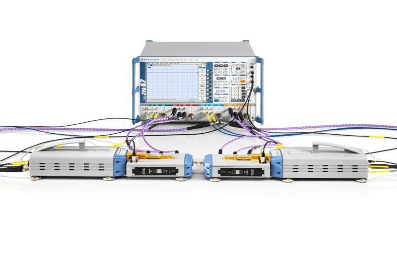
 ZVA-Z110E F Band (WR08) ZVA-Z110 ZVA-Z75 ZVA-Z90 E Band (WR12) W Band (WR10) Manual Attenuator Electronic Attenuator V Band")
2 Millimeter Wave Converter Family ZVA-Z500 ZVA-Z325 Y Band (WR02) ZVA-Z220 J Band (WR03) ZVA-Z170 G Band (WR05) ZVA-Z140 D Band (WR06) ZVA-Z110E F Band (WR08) ZVA-Z110 ZVA-Z75 ZVA-Z90 E Band (WR12) W Band (WR10) Manual Attenuator Electronic Attenuator V Band (WR15)
3 Converter block diagram (ZVA-Z110, WR10 band) REF LNA +20dB Legend: Waveguide WR10 N = 8 Coaxial (PC3,5/SMA) Attenuator (manual) M = 6 TEST PORT x3 x2 RF LO N = 8 +10dB LNA +20dB MEAS
4 Rohde & Schwarz ZVA-Z110 RF, LO, IF parameters ı Source Input (from VNA): Frequency Range: 12.5 GHz to GHz (x6) Input power range: +4 dbm to +10 dbm ı Local Oscillator Input (from VNA/ext source) Frequency Range: GHz to GHz (x8) Input power Range: +5 dbm to +10dBm ı Measurement/Reference Output (to VNA) Frequency Range: 10 MHz to 300 MHz


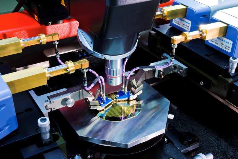
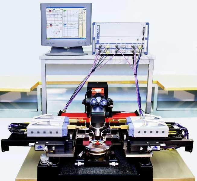
5 Material measurements in the millimeter wave range 5
6 Amplifier Characterization Compression point measurement, e.g. 1dB CP ı Requires power sweep capability ı For accurate compression measurements we need A flat input DUT input A defined (calibrated) power DUT input ı Consequence : Power calibration is a must 6

7 ZVA-Z110E with electronic power control ı 75 to 110GHz with electronic power control ı 0 to 25 db attenuation ı Allows power sweep and compression point measurement on amplifiers

8 Electronic power control Full automatic compression point measurement at 110 GHz To R&S ZVA-Z110E 25dB Electronic Power Sweep Range Option R&S ZVA-B8
9 Power Sweep by RF input variation Example WR10 band ı Power sweep range of 70dB by RF input power variation ı Frequency dependency can be calibrated out by software tool Output power relative to max output power / 75, 80, 85, 90, 95, 100, 105 and 110 GHz RFin power / dbm
10 Power Calibration in the millimeter wave range


11 Precise power calibration up to 110GHz Unique power measurements from DC up to 110GHz with 1.0mm connector First millimeterpower sensor that is traceable to a national metrology institute S-Parameters of waveguide transition can be loaded directly into sensor for accurate power measurements USB interface means the power sensor can be used directly with the ZVA or PC running the free NRP analysis software. Lowest uncertainty to 0.318dB Highest Linearity 30% faster than competition

 PM4/5")

12 Power calibration above 110GHz Compatibility for power measurements up to 220GHz with the ELVA DPM power meter. Compatibility with VDI (Erickson) PM4/5 Calorimeter power meter for use from 75GHz to 2 THz. Flexible ZVA external device implementation allows customer developed drivers
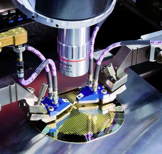
13 Power Calibration on the Wafer WR10 Wafer
14 Challenges for accurate Power Levels On-Wafer Goal : Power calibration in the reference plane of the DUT (amplifier) Problem : No access with coaxial power meter possible Solution: ı Characterization of the S-parameter between coaxial interface and the wafer prober tip ı Correction of the coaxial power calibration with this loss list

15 Power Correction with Loss List Coax plane Loss list Wafer


16 Power Calibration in Reference Plane on the Wafer 1st Step: UOSM calibration to characterize the connection between coaxial interface and onwafer reference plane Power loss list for each port Alternatively Delta Calibration between coaxial plane and On-Wafer plane 1 mm Match ISS-Match Unknown Through 2nd Step: Power calibration at the coaxial interfaces using the power loss list from the 1st step.


17 Millimeter Wave Imaging Systems Phase Error Sensitivity Tera Hertz : New opportunities for industry 3-5 February 2015
18 Technology choices + technology reuse + sufficient RF power + high bandwidth + mm resolution + good penetration + 3D Images + Compact Planar 2D-Array + feasible + Reduce cost + Reduce power + faster E-Band Multistatic sparse array + high dynamic range + indoor operation Active system Digital- Beamforming + synthetic focusing + high flexibility + adjustable illumination 18


19 Multistatic imaging - Focusing 2D-Array x z Tx Rx y Reconstruction in space domain 19
 ı Scanner detects the reflected (backscattered) signal from the skin or concealed objects")
 metallic and non-metallic plastics ceramics explosives liquids and gels powder Incident wave")
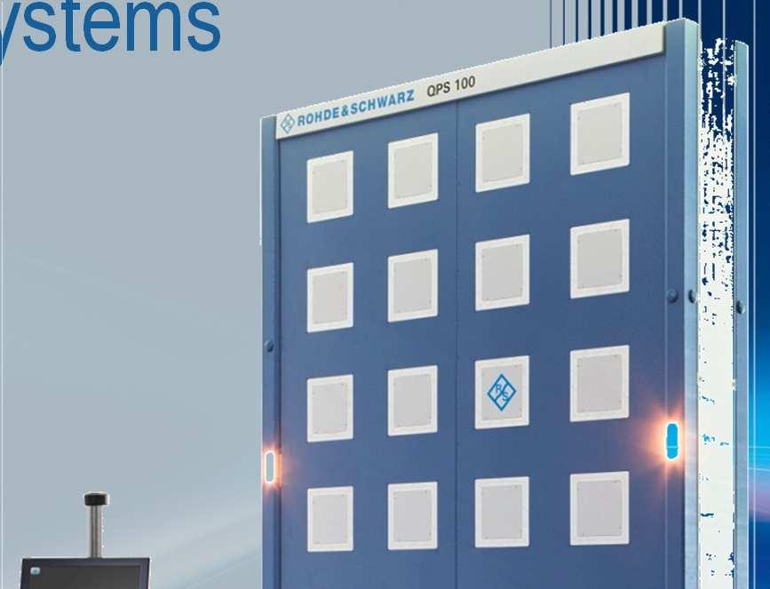
20 Principle of Operation ı Person is illuminated by microwaves with very low intensity (No X-rays non ionizing radiation) ı Waves penetrate the clothing (but not the skin) ı Scanner detects the reflected (backscattered) signal from the skin or concealed objects ı Unique technique analysing reflections from floor mirror ı Automatic evaluation and analysis of image data by an automatic detection software (algorithm) metallic and non-metallic plastics ceramics explosives liquids and gels powder Incident wave Reflected wave 20
 64 ms for QPS200 (single) ı Frequency 70")
 10 sec (QPS100, complete result) 7 sec (QPS200,")
21 Technical Overview Panel Cluster 94 receive antennas ı Aperture 2 m x 1 m ı 3008 Tx & 3008 Rx elements in 32 Clusters ı Data acquisition time 16 ms for QPS100 (per scan) 64 ms for QPS200 (single) ı Frequency 70 to 80 GHz (λ 4 mm) 94 transmit antennas ı High resolution < 2 mm ı Image dynamic range > 30 db ı Processing time 7 sec (QPS100, result of front scan) 10 sec (QPS100, complete result) 7 sec (QPS200, complete result) 21


22 System Block Diagram 22

23 Digital Signal Processing Chain digitized IF signals DDC, lowpass filter correct for system drift system error correction image reconstruction automatic detection algorithm detection result 23
24 Sources of Noise ı Various sources of errors within the system ı Dominant errors: Thermal noise of receiver Phase noise of signal source Temperature drift (phase drift of received signal), compensated by referencing Antenna crosstalk, compensated by system error correction ı Noise affects performance of compensation 24


25 Cross-coupling ı As a systematic signal, residual cross-coupling shows up as artifact within the microwave image 25


26 Test scenario ideal image ı Resolution test chart ı Dynamic range test ( bed of nails ) ı Heavy averaging used for best available data quality more than 40 db noise and artifact free image dynamic range ı This data is used as reference data set and modified by adding systematic and random phase errors ı The modified data are reconstructed and effects of phase errors on image quality are examined 26
 ı Systematic phase drift of 20 degree added to raw data ı Cross-coupling is not compensated completely shows up as artifact ı Dynamic range is decreased to 27 db ı")
27 Test scenario systematic phase drift added (e.g. temperature drift) ı Systematic phase drift of 20 degree added to raw data ı Cross-coupling is not compensated completely shows up as artifact ı Dynamic range is decreased to 27 db ı When omitting channels with high cross-coupling from adjacent transmitters, dynamic range is 33 db complete dataset high-cc omitted 27
28 Systematic Phase Errors - Summary ı Normally the cross coupling between the antennas is calibrated out (Match calibration) ı But if temperature drift (= phase error, phase drift) happens the cross coupling can not be fully eliminated ı Consequence : Artifacts come up in the picture ı Measures : Omitting channels with high cross coupling 28
 complete dataset ı Random phase drift, standard deviation 20 degree added to raw data ı Random error no systematic artifacts, but significant increase in noise level ı")
29 Test scenario random phase added (e.g. source phase noise) complete dataset ı Random phase drift, standard deviation 20 degree added to raw data ı Random error no systematic artifacts, but significant increase in noise level ı Dynamic range is decreased to 33 db ı When omitting channels with high cross-coupling from adjacent transmitters, dynamic range is 36 db high-cc omitted 29
30 Random Phase Errors - Summary ı Noise level increases ı No artifacts ı Consequences : Decrease in dynamic range Unclear picture ı Measures : Reference channels near Tx/Rx antennas Omitting channels with high cross coupling 30


31 Other application areas for microwave imaging Non-Destructive Test with 3D-Pictures (QPS100) 31

32 Thank you for your attention 1950 : World s first Vector Network Analyzer - made by R&S Direct display of S-Parameters in a complex plane > 50 years of experience in network analysis
Νέες Τεχνολογίες Σάρωσης Σώματος για Ασφαλείς Διελεύσεις. 5o SECURITY PROJECT Μαΐου 2017 Αθήνα, Divani Caravel
 Νέες Τεχνολογίες Σάρωσης Σώματος για Ασφαλείς Διελεύσεις 5o SECURITY PROJECT 2017 26 Μαΐου 2017 Αθήνα, Divani Caravel Where do we come from Manufacturers of mobile radios and other wireless devices Operators
Test & Measurement. Technical Information. R&S ZV-WR10 / -WR12 / -WR15 Calibration Kits
 Test & Measurement 1307.7174.92 03 Technical Information R&S ZV-WR10 / -WR12 / -WR15 Calibration Kits This technical information describes the following calibration kits: R&S ZV-WR10 (without Sliding Match
Unique Applications of microwave VNA technology. Ben Maarleveld - Sales Manager T&M - Rohde & Schwarz Benelux B.V.
 Unique Applications of microwave VNA technology Ben Maarleveld - Sales Manager T&M - Rohde & Schwarz Benelux B.V. Reaction to terrorist incidents security measures increased strongly Traditionally metal
A True Differential Millimeter Wave System with Port Power Control. Presented by: Suren Singh
 A True Differential Millimeter Wave System with Port Power Control Presented by: Suren Singh Agenda Need for True Differential and RF Power Control Vector Network Analyzer RF Port Power Control Port Power
R&S ZVA-Zxx Millimeter-Wave Converters Network analysis up to 500 GHz
 ZVA-Zxx_bro_en_5214-2033-12.indd 1 Product Brochure 06.02 Test & Measurement R&S ZVA-Zxx Millimeter-Wave Converters Network analysis up to 500 GHz 28.10.2014 21:05:04 R&S ZVA-Zxx Millimeter-Wave Converters
THz Vector Network Analyzer Development & Measurements
 THz Vector Network Analyzer Development & Measurements Jeffrey L Hesler, Yiwei Duan, Brian Foley and Thomas Crowe Virginia Diodes Inc., Charlottesville, VA, USA Abstract: Virginia Diodes has been developing
Beamforming measurements. Markus Loerner, Market Segment Manager RF & microwave component test
 Beamforming measurements Markus Loerner, Market Segment Manager RF & microwave component test Phased Arrays not a new concept Airborne ı Phased Array Radars: since the 60 s ı Beams are steerable electronically
Testing Millimeter-Wave Mixers Using Converters of the R&S ZVA Family
 Products: R&S ZVA-Z75, R&S ZVA-Z110, R&S ZVA-Z325, R&S ZVA24, R&S ZVA40, R&S ZVA50, R&S ZVT20, R&S SM100A, R&S ZV-WR15, R&S ZV-WR10, R&S ZV-WR03, R&S NRP, R&S NRP-Z22 Testing Millimeter-Wave Mixers Using
Waveguide Calibration with Copper Mountain Technologies VNA
 Clarke & Severn Electronics Ph: +612 9482 1944 BUY NOW www.cseonline.com.au Introduction Waveguide components possess certain advantages over their counterpart devices with co-axial connectors: they can
R&S NRP Power Meter Family Specifications
 R&S NRP Power Meter Family Specifications year Data Sheet Version 06.00 CONTENTS Definitions... 3 Overview of the R&S NRP power sensors... 4 Specifications in brief of the R&S NRP power sensors... 5 Multipath
Millimeter Wave Solutions from R&S
 Millimeter Wave Solutions from R&S R&S Portfolio Network Analyzers 100 khz (biast) 100 khz (biast) ZVA110. ZVA24/40/50/67, ZVT20 with External Converters ZV-Zxyz ZVA67 [2 & 4 ports, 2 or 4 sources, 1.85mm(m)]
Testing S-Parameters on Pulsed Radar Power Amplifier Modules
 Application Note Mahmud Naseef, Roland Minihold, Thilo Bednorz 3.2013-1MA126_2E Testing S-Parameters on Pulsed Radar Power Amplifier Modules Application Note Products: ı ı ı ı ı R&S ZVA8 R&S ZVAX24 R&S
Vector Network Analyzer Application note
 Vector Network Analyzer Application note Version 1.0 Vector Network Analyzer Introduction A vector network analyzer is used to measure the performance of circuits or networks such as amplifiers, filters,
Platform Migration 8510 to PNA. Graham Payne Application Engineer Agilent Technologies
 Platform Migration 8510 to PNA Graham Payne Application Engineer Agilent Technologies We set the standard... 8410 8510 When we introduced the 8510, we changed the way S-parameter measurements were made!
High Performance, Broadband Network Analysis Solutions
 Advanced Test Equipment Rentals E stablished 1981 www.atecorp.com 800-404-ATEC (2832) Technical Data Sheet & Configuration Guide High Performance, Broadband Network Analysis Solutions ME7838A Series Vector
Vector Network Analyzer
 Vector Network Analyzer VNA Basics VNA Roadshow Budapest 17/05/2016 Content Why Users Need VNAs VNA Terminology System Architecture Key Components Basic Measurements Calibration Methods Accuracy and Uncertainty
Calibration and Accuracy in Millimeter Systems. Keith Anderson
 IMS2011 in Baltimore: A Perfect Match Calibration and Accuracy in Millimeter Systems Keith Anderson Agilent Technologies Copyright 2010 Agilent Technologies, Inc. Agenda Interfaces S-parameter calibration
R&S NRP USB and LAN Power Sensors Specifications
 R&S NRP USB and LAN Power Sensors Specifications year Test & Measurement Data Sheet 04.00 CONTENTS Definitions... 3 Overview of the R&S NRP power sensors... 4 Specifications in brief of the R&S NRP power
PLANAR 814/1. Vector Network Analyzer
 PLANAR 814/1 Vector Network Analyzer Frequency range: 100 khz 8 GHz Measured parameters: S11, S12, S21, S22 Wide output power range: -60 dbm to +10 dbm >150 db dynamic range (1 Hz IF bandwidth) Direct
E-band and mmwave Components & Sub-Assemblies testing Challenges New Technology. VNA Roadshow Budapest 17/05/2016
 E-band and mmwave Components & Sub-Assemblies testing Challenges New Technology VNA Roadshow Budapest 17/05/2016 Agenda Applications drive the need Challenges faced by device characterization engineers
Optoelectronic Components Testing with a VNA(Vector Network Analyzer) VNA Roadshow Budapest 17/05/2016
 VNA Roadshow Budapest 17/05/2016") Optoelectronic Components Testing with a VNA(Vector Network Analyzer) VNA Roadshow Budapest 17/05/2016 Content Introduction Photonics & Optoelectronics components Optical Measurements VNA (Vector Network
Optoelectronic Components Testing with a VNA(Vector Network Analyzer) VNA Roadshow Budapest 17/05/2016 Content Introduction Photonics & Optoelectronics components Optical Measurements VNA (Vector Network
Configuration of PNA-X, NVNA and X parameters
 Configuration of PNA-X, NVNA and X parameters VNA 1. S-Parameter Measurements 2. Harmonic Measurements NVNA 3. X-Parameter Measurements Introducing the PNA-X 50 GHz 43.5 GHz 26.5 GHz 13.5 GHz PNA-X Agilent
Technologies Vector Reflectometers
 Overview Reflectometers are used to measure the reflection, or S11 parameter, of a Device Under Test (DUT). This measurement only provides characterization of a single-ended device. For analysis of a twoport
Ultra High Frequency Measurements
 Ultra High Frequency Measurements Desmond Fraser desmond@rheintech.com 703.689.0368 360 Herndon Parkway Suite 1400 Herndon, VA 20170 IEEE EMC DC / N. VA Chapter 31 January 2012 Overview We ll review Millimeter
Network Analysis Basics
 Adolfo Del Solar Application Engineer adolfo_del-solar@agilent.com MD1010 Network B2B Agenda Overview What Measurements do we make? Network Analyzer Hardware Error Models and Calibration Example Measurements
Vector Network Analysis
 Portfolio Brochure Vector Network Analysis Product Portfolio Vector Network Analysis VNA Innovation Timeline In 1965, Anritsu filed the patent that defined the first modern Vector Network Analyzer (VNA).
Emission of mm-wave and THz Scanners
 Emission of mm-wave and THz Scanners Thomas Kleine-Ostmann Working Group 2.21 Electromagnetic Fields and Antenna Measuring Techniques THz Security Workshop Davos, Switzerland, 29 th May, 2015 1 Content
PLANAR S5048 and TR5048
 PLANAR S5048 and TR5048 Vector Network Analyzers KEY FEATURES Frequency range: 20 khz 4.8 GHz COM/DCOM compatible for LabView Measured parameters: and automation programming S11, S12, S21, S22 (S5048)
Abstract: Stringent system specifications impose tough performance requirements on the RF and microwave cables used in aerospace and defense
 1 Abstract: Stringent system specifications impose tough performance requirements on the RF and microwave cables used in aerospace and defense communication systems. With typical tools, it can be very
Antenna Measurement using Vector Network Analyzer. Jong-hwan Keum Agilent Technologies
 Antenna Measurement using Vector Network Analyzer Jong-hwan Keum Agilent Technologies Agenda Overview Antenna Measurement System Configuration(Examples) Antenna Measurement System Design Considerations
SERIES PLS PHASE LOCKED SYNTHESIZER. FEATURES: Small Size, Low Cost, Simple to use Low Phase Noise Auto-sensing Internal or External 10MHz Reference
 PHASE LOCKED SYNTHESIZER FEATURES: Small Size, Low Cost, Simple to use Low Phase Noise Auto-sensing Internal or External 10MHz Reference Can be utilized as a synthesizer, or a fixed frequency oscillator
Spectrum and signal analyzers for every requirement an overview
 Spectrum and signal analyzers for every requirement an overview The introduction of the Handheld Spectrum Analyzer R&S FSH6 (page 26) expands an already full range of analyzers from Rohde & Schwarz, covering
Power Added Efficiency Measurement with R&S ZNB/ R&S ZVA
 Power Added Efficiency Measurement with R&S ZNB/ R&S ZVA Application Note Products: R&S ZNB R&S ZVA Power Added Efficiency (PAE) is a key parameter for the characterization of an amplifier. This application
LA Techniques Ltd
 8 GHz Vector Network Analyser Product overview 300 khz 8 GHz range 120 db dynamic range Flexible architecture 200µs sweep speed Signal generator mode Outstanding value The LA19-13-13 is a PC-driven Vector
EXHIBIT 7: MEASUREMENT PROCEDURES Pursuant 47 CFR 2.947
 EXHIBIT 7: MEASUREMENT PROCEDURES Pursuant 47 CFR 2.947 7.1 RF Power -- Pursuant to 47 CFR 2.947(c) Method of Conducted Output Power Measurement: Adaptation of TIA/EIA-603-A clause 2.2.1 for Pulsed Measurements
R&S ZVT Vector Network Analyzer Specifications
 R&S ZVT Vector Network Analyzer Specifications Test & Measurement Data Sheet 08.00 CONTENTS Definitions... 3 Specifications... 4 Measurement range...4 Measurement speed...5 Measurement accuracy...6 Effective
Spurious and Stability Analysis under Large-Signal Conditions using your Vector Network Analyser
 Spurious and Stability Analysis under Large-Signal Conditions using your Vector Network Analyser An application of ICE June 2012 Outline Why combining Large-Signal and Small-Signal Measurements Block Diagram
Keysight Technologies Gustaaf Sutorius
 1 1 mmw Seminar 2017 Keysight Technologies 18-04-2018 Gustaaf Sutorius Introduction & Agenda Why mmwave Industry needs & mmwave challenges Generating mmwave Analyzing mmwave Characterizing mmwave components
The path from 4G to 5G: Technology development from the test & measurement perspective. Dr. Taro Eichler. 5G Tokyo Bay Summit July 23 rd, 2015
 The path from 4G to 5G: Technology development from the test & measurement perspective Dr. Taro Eichler 5G Tokyo Bay Summit July 23 rd, 2015 5G Use cases: Much more than only Mobile Broadband Scenarios
A Method for Gain over Temperature Measurements Using Two Hot Noise Sources
 A Method for Gain over Temperature Measurements Using Two Hot Noise Sources Vince Rodriguez and Charles Osborne MI Technologies: Suwanee, 30024 GA, USA vrodriguez@mitechnologies.com Abstract P Gain over
R&S NRP-Zxx Power Sensors Specifications
 R&S NRP-Zxx Power Sensors Specifications year Data Sheet Version 11.00 CONTENTS Definitions... 3 Overview of the R&S NRP-Zxx power sensors... 4 Specifications in brief of the R&S NRP-Zxx power sensors...
5 ESSENTIAL HINTS TO IMPROVE Millimeter-wave Network Analysis
 5 ESSENTIAL HINTS TO IMPROVE Millimeter-wave Network Analysis Contents 5 Essential Hints to Improve Millimeter-wave Network Analysis Ensure Accurate, Repeatable Results Go to Hint 1 > Calibrate for Better
FieldFox Handheld Education Series Part 3: Calibration Techniques for Precise Field Measurements
 FieldFox Handheld Education Series Part 3: Calibration Techniques for Precise Field Measurements FieldFox Handheld Education Series Interference Testing Cable and Antenna Measurements Calibration Techniques
A TECHNIQUE TO EVALUATE THE IMPACT OF FLEX CABLE PHASE INSTABILITY ON mm-wave PLANAR NEAR-FIELD MEASUREMENT ACCURACIES
 A TECHNIQUE TO EVALUATE THE IMPACT OF FLEX CABLE PHASE INSTABILITY ON mm-wave PLANAR NEAR-FIELD MEASUREMENT ACCURACIES Daniël Janse van Rensburg Nearfield Systems Inc., 133 E, 223rd Street, Bldg. 524,
RF power measurement in. three-mixer method
 RF power measurement in D-band using downconverter calibrated by three-mixer method Katsumi Fujii a), Toshihide Tosaka, Kaori Fukunaga, and Yasushi Matsumoto National Institute of Information and Communications
Compact Series: S5065 & S5085 Vector Network Analyzers KEY FEATURES
 Compact Series: S5065 & S5085 Vector Network Analyzers KEY FEATURES Frequency range: 9 khz - 6.5 or 8.5 GHz Measured parameters: S11, S12, S21, S22 Wide output power adjustment range: -50 dbm to +5 dbm
Compact Series: S5048 & TR5048 Vector Network Analyzers KEY FEATURES
 Compact Series: S5048 & TR5048 Vector Network Analyzers KEY FEATURES Frequency range: 20 khz - 4.8 GHz Measured parameters: S11, S12, S21, S22 (S5048) S11, S21 (TR5048) Wide output power adjustment range:
R&S NRPM Over-the-Air (OTA) Power Measurement Solution For 5G, WLAN IEEE ad and IEEE ay
 Power Measurement Solution For 5G, WLAN IEEE ad and IEEE ay") year Product Brochure Version 0.00 R&S NRPM Over-the-Air (OTA) Power Measurement Solution For 5G, WLAN IEEE 80.ad and IEEE 80.ay NRPM_bro_en_607-4687-_v000.indd 8.0.09 5:59:08 R&S NRPM Over-the-Air (OTA)
year Product Brochure Version 0.00 R&S NRPM Over-the-Air (OTA) Power Measurement Solution For 5G, WLAN IEEE 80.ad and IEEE 80.ay NRPM_bro_en_607-4687-_v000.indd 8.0.09 5:59:08 R&S NRPM Over-the-Air (OTA)
EXTEND YOUR REACH. Copper Mountain Technologies USB VNAs. S-parameter measurement solutions from 9 khz to 110 GHz Measured parameters from S 11
 Copper Mountain Technologies USB VNAs S-parameter measurement solutions from 9 khz to 110 GHz Measured parameters from S 11 to S 44 Dynamic range as high as 162 db typ. (1 Hz IF bandwidth) Measurement
Panel Session: 5G Test and Measurement
 IEEE 5G Summit Panel Session: 5G Test and Measurement Malcolm Robertson, Keysight Jon Martens, Anritsu Chris Scholz, Rohde & Schwarz Jason White, National Instruments Moderator: Kate A. Remley, NIST So
Millimeter Signal Measurements: Techniques, Solutions and Best Practices
 New Network Analyzer platform Millimeter Signal Measurements: Techniques, Solutions and Best Practices Phase Noise measurements update 1 N522XA PNA Series Network Analyzer Introducing Highest Performance
Project: IEEE P Working Group for Wireless Personal Area Networks (WPANs)
") Project: IEEE P802.15 Working Group for Wireless Personal Area Networks (WPANs) Title: A first 300 GHz Phased Array Antenna Date Submitted: 11. July 2017 Source: Sebastian Rey, Technische Universität Braunschweig
Project: IEEE P802.15 Working Group for Wireless Personal Area Networks (WPANs) Title: A first 300 GHz Phased Array Antenna Date Submitted: 11. July 2017 Source: Sebastian Rey, Technische Universität Braunschweig
Agilent Millimeter-Wave Network Analyzers 10 MHz to 110 GHz, with Extensions to 1.1 THz. Technical Overview
 Agilent Millimeter-Wave Network Analyzers 10 MHz to 110 GHz, with Extensions to 1.1 THz Technical Overview Single Sweep 10 MHz to 110 GHz Measurement Solutions Currently there are two solutions that offer
Keysight Technologies Techniques for Precise Cable and Antenna Measurements in the Field
 Keysight Technologies Techniques for Precise Cable and Antenna Measurements in the Field Using FieldFox handheld analyzers Application Note This application note introduces the practical aspects of cable
PLANAR R54. Vector Reflectometer KEY FEATURES
 PLANAR R54 Vector Reflectometer KEY FEATURES Frequency range: 85 MHz 5.4 GHz Reflection coefficient magnitude and phase, cable loss, DTF Transmission coefficient magnitude when using two reflectometers
International Journal of Engineering & Computer Science IJECS-IJENS Vol:13 No:03 1
 International Journal of Engineering & Computer Science IJECS-IJENS Vol:13 No:03 1 Characterization of Millimetre waveband at 40 GHz wireless channel Syed Haider Abbas, Ali Bin Tahir, Muhammad Faheem Siddique
Technical Information
 Technical Information Power Sensors R&S NRP-Z51, -Z55 Thermoelectric accuracy at its best The new power sensors for the frequency ranges DC to 18 GHz (R&S NRP-Z51) and DC to 40 GHz (R&S NRP-Z55) for the
Holography Transmitter Design Bill Shillue 2000-Oct-03
 Holography Transmitter Design Bill Shillue 2000-Oct-03 Planned Photonic Reference Distribution for Test Interferometer The transmitter for the holography receiver is made up mostly of parts that are already
Novel Method for Vector Mixer Characterization and Mixer Test System Vector Error Correction. White Paper
 Novel Method for Vector Mixer Characterization and Mixer Test System Vector Error Correction White Paper Abstract This paper presents a novel method for characterizing RF mixers, yielding magnitude and
Enabling autonomous driving
 Automotive fuyu liu / Shutterstock.com Enabling autonomous driving Autonomous vehicles see the world through sensors. The entire concept rests on their reliability. But the ability of a radar sensor to
S3602A/B Vector Network Analyzer Datasheet
 S3602A/B Vector Network Analyzer Datasheet Saluki Technology Inc. The document applies to the vector network analyzers of the following models: S3602A vector network analyzer (10MHz-13.5GHz). S3602B vector
Contents. CALIBRATION PROCEDURE NI PXIe GHz and 14 GHz RF Vector Signal Analyzer
 CALIBRATION PROCEDURE NI PXIe-5665 3.6 GHz and 14 GHz RF Vector Signal Analyzer This document contains the verification procedures for the National Instruments PXIe-5665 (NI 5665) RF vector signal analyzer
Harmonic Mixers And their application with Spectrum Analysers Application Note Revision: February 2009
 General A harmonic mixer is another term for a sub-harmonic mixer (SHM) but is more commonly used for systems using higher multiples of the input local oscillator (LO) to produce the mixing LO. They lend
MICROWAVE MICROWAVE TRAINING BENCH COMPONENT SPECIFICATIONS:
 Microwave section consists of Basic Microwave Training Bench, Advance Microwave Training Bench and Microwave Communication Training System. Microwave Training System is used to study all the concepts of
Agilent 8360B/8360L Series Synthesized Swept Signal/CW Generators 10 MHz to 110 GHz
 Agilent 8360B/8360L Series Synthesized Swept Signal/CW Generators 10 MHz to 110 GHz ity. l i t a ers V. n isio c e r P. y t i l i ib Flex 2 Agilent 8360 Synthesized Swept Signal and CW Generator Family
Calibration and Validation for Automotive EMC
 Calibration and Validation for Automotive EMC Wolfgang Müllner Patrick Preiner Alexander Kriz Seibersdorf Labor GmbH 2444 Seibersdorf, Austria http://rf.seibersdorf-laboratories.at rf@seibersdorf-laboratories.at
Optical Delay Line Application Note
 1 Optical Delay Line Application Note 1.1 General Optical delay lines system (ODL), incorporates a high performance lasers such as DFBs, optical modulators for high operation frequencies, photodiodes,
[APP NOTE TITLE] Application Profile. Challenges
![[APP NOTE TITLE] Application Profile. Challenges](/thumbs/96/126831407.jpg "[APP NOTE TITLE] Application Profile. Challenges") [APP NOTE TITLE] 03/23/2018 Application Profile Wireless infrastructure encompasses a broad range of radio technologies, antennas, towers, and frequencies. Radio networks are built from this infrastructure
[APP NOTE TITLE] 03/23/2018 Application Profile Wireless infrastructure encompasses a broad range of radio technologies, antennas, towers, and frequencies. Radio networks are built from this infrastructure
TEST & MEASURING INSTRUMENTS. Analyzer. (4 Ports) 4 Ports
 4 Ports") TEST & MEASURING INSTRUMENTS Analyzer (4 Ports) 4 Ports Key Features Frequrncy Range : 100kHz ~ 8GHz, 16 Parameters support (S11 ~ S44) Measurement time per point : 100us per point Wide Output Power Range
TEST & MEASURING INSTRUMENTS Analyzer (4 Ports) 4 Ports Key Features Frequrncy Range : 100kHz ~ 8GHz, 16 Parameters support (S11 ~ S44) Measurement time per point : 100us per point Wide Output Power Range
Impact of mm-wave Range and Large Bandwidth on RF System Design. R&S Taiwan Feiyu Chen
 Impact of mm-wave Range and Large Bandwidth on RF System Design R&S Taiwan Feiyu Chen Simplified RF Architecture ı ITU Band 11 (Extremely High Frequency) 30 to 300 GHz ı Wavelength range 1 to 10 mm Digital
FEASIBILITY STUDY ON FULL-DUPLEX WIRELESS MILLIMETER-WAVE SYSTEMS. University of California, Irvine, CA Samsung Research America, Dallas, TX
 2014 IEEE International Conference on Acoustic, Speech and Signal Processing (ICASSP) FEASIBILITY STUDY ON FULL-DUPLEX WIRELESS MILLIMETER-WAVE SYSTEMS Liangbin Li Kaushik Josiam Rakesh Taori University
EXTEND YOUR REACH GHz 60-90GHz GHz
 EXTEND YOUR REACH 50-75 GHz 60-90GHz 75-110 GHz Extend Your Reach Farran Technology and Copper Mountain Technologies, globally recognized innovators, with a combined 50 years experience in RF test and
Receiver Design for Passive Millimeter Wave (PMMW) Imaging
 Imaging") Introduction Receiver Design for Passive Millimeter Wave (PMMW) Imaging Millimeter Wave Systems, LLC Passive Millimeter Wave (PMMW) sensors are used for remote sensing and security applications. They rely
Introduction Receiver Design for Passive Millimeter Wave (PMMW) Imaging Millimeter Wave Systems, LLC Passive Millimeter Wave (PMMW) sensors are used for remote sensing and security applications. They rely
PM Series Microwave Power Calibration System
 PM Series Microwave Power Calibration System Supports Sensors from most major manufacturers from 6 khz to 50 GHz Faster than direct compare method Lowest total uncertainty National Metrology Institute
CobaltFx Series EXTEND YOUR REACH. Frequency Extender System from. Frequency bands from: GHz, GHz, GHz
 CobaltFx Series TM Frequency Extender System from TM Frequency bands from: 50-75 GHz, 60-90 GHz, 75-110 GHz EXTEND YOUR REACH USA: +1.17..5400 61 E. New York St Indianapolis, IN 460 www.coppermountaintech.com
Improved Measurement of Passive Intermodulation Products
 Presentation to: ANAMET Improved Measurement of Passive Intermodulation Products James Miall Date: March 2004 Introduction PIM = Passive InterModulation IMD = InterModulation Distortion PIM is mixing of
R&S ZVT Vector Network Analyzer Specifications
 ZVT_dat-sw_en_0758-065-22_v0900_cover.indd Data Sheet 09.00 Test & Measurement R&S ZVT Vector Network Analyzer Specifications 06.03.205 5:50:4 CONTENTS Definitions... 3 Specifications... 4 Measurement
Banded Milimeter Wave Network Analysis TECHNICAL OVERVIEW
 Banded Milimeter Wave Network Analysis TECHNICAL OVERVIEW Banded Measurement Solutions to 1.5 THz Keysight offers a variety of banded millimeter-wave solutions that enable the PNA/ PNA-X network analyzers
Agilent Technologies Gli analizzatori di reti della serie-x
 Agilent Technologies Gli analizzatori di reti della serie-x Luigi Fratini 1 Introducing the PNA-X Performance Network Analyzer For Active Device Test 500 GHz & beyond! 325 GHz 110 GHz 67 GHz 50 GHz 43.5
S3602C Vector Network Analyzer Datasheet
 S3602C Vector Network Analyzer Datasheet Saluki Technology Inc. The document applies to the vector network analyzers of the following models: S3602C vector network analyzer (10MHz - 43.5GHz). Options of
Confidence. on the Cutting Edge. Vector Network Analyzer Portfolio Brochure. In the Lab On the Manufacturing Floor In the Field. Anritsu Since 1895
 Anritsu Since 1895 Vector Network Analyzer Portfolio Brochure Confidence on the Cutting Edge In the Lab On the Manufacturing Floor In the Field For every measurement scenario from on-wafer device characterization
Ultra Wideband Indoor Radio Channel Measurements
 Ultra Wideband Indoor Radio Channel Measurements Matti Hämäläinen, Timo Pätsi, Veikko Hovinen Centre for Wireless Communications P.O.Box 4500 FIN-90014 University of Oulu, FINLAND email: matti.hamalainen@ee.oulu.fi
MA24104A. Inline High Power Sensor. True-RMS, 600 MHz to 4 GHz
 Product Brochure MA24104A Inline High Power Sensor True-RMS, 600 MHz to 4 GHz A Standalone, Compact, and Highly Accurate Inline High Power Sensor for your RF Power Measurement Needs MA24104A at a Glance
Overcoming Mixer Measurement Challenges
 Overcoming Mixer Measurement Challenges October 10, 2002 presented by: Robb Myer Dave Ballo Today we will be looking at overcoming measurements challenges associated with frequency translating devices
Improving Amplitude Accuracy with Next-Generation Signal Generators
 Improving Amplitude Accuracy with Next-Generation Signal Generators Generate True Performance Signal generators offer precise and highly stable test signals for a variety of components and systems test
Frequency Extender Systems Frequency bands from: GHz, GHz, GHz, GHz FEV Frequency Extender System in Collaboration with
 CobaltFx Series TM Frequency Extender Systems Frequency bands from: 1-5 GHz, 50-75 GHz, 0-90 GHz, 75-110 GHz FEV Frequency Extender System in Collaboration with EXTEND YOUR REACH TM USA: +1.17..500 info@coppermountaintech.com
E/O and O/E Measurements with the 37300C Series VNA
 APPLICATION NOTE E/O and O/E Measurements with the 37300C Series VNA Lightning VNA Introduction As fiber communication bandwidths increase, the need for devices capable of very high speed optical modulation
Frequency Extension Systems Frequency bands from: GHz, GHz, GHz, GHz FEV Frequency Extenders in collaboration with
 CobaltFx Series TM Frequency Extension Systems Frequency bands from: 18-5 GHz, 50-75 GHz, 0-90 GHz, 75-110 GHz FEV Frequency Extenders in collaboration with EXTEND YOUR REACH TM USA: +1.17..500 info@coppermountaintech.com
Agilent Millimeter-Wave Network Analyzers 10 MHz to 110 GHz, with Extensions to 1.1 THz. Technical Overview
 Agilent Millimeter-Wave Network Analyzers 10 MHz to 110 GHz, with Extensions to 1.1 THz Technical Overview Single Sweep 10 MHz to 110 GHz Measurement Solution Agilent currently offers the N5251A single
Compact MIMO Antenna with Cross Polarized Configuration
 Proceedings of the 4th WSEAS Int. Conference on Electromagnetics, Wireless and Optical Communications, Venice, Italy, November 2-22, 26 11 Compact MIMO Antenna with Cross Polarized Configuration Wannipa
X-Parameters with Active and Hybrid Active Load Pull
 X-Parameters with Active and Hybrid Active Load Pull Gary Simpson, CTO Maury Microwave EuMW 2012 www.maurymw.com 1 General Load Pull Overview 2 Outline 1. Introduction to Maury Microwave 2. Basics and
Double-Ridged Waveguide Horn
 Model 3106 200 MHz 2 GHz Uniform Gain Power Handling up to 1.6 kw Model 3115 1 GHz 18 GHz Low VSWR Model 3116 18 GHz 40 GHz Quality Construction M O D E L 3 1 0 6 Double-Ridged Waveguide Horn PROVIDING
Broadband Millimeter-wave FMCW Radar for Imaging of Humans
 Broadband Millimeter-wave FMCW Radar for Imaging of Humans A. Dallinger, S. Schelkshorn, J. Detlefsen Technische Universität München, Lehrstuhl für Hochfrequenztechnik, Fachgebiet Hochfrequente Felder
SAGE Millimeter, Inc.
 Description: Model SAM-5735930395-15-L1-4W is a linear polarized, 58 GHz microstrip patch 1 x 4 array antenna. The antenna array implements four individual antenna ports so that beamforming can be achieved
Exercise 5: Power amplifier measurement
 Exercise 5: Power amplifier measurement The objective of this laboratory exercise is the calibrated measurement of important parameters of a power amplifier. This includes performance parameters like gain,
Keysight Technologies UWB Antenna Measurements with the 20 GHz E5071C ENA Network Analyzer. Application Note
 Keysight Technologies UWB Antenna Measurements with the 20 GHz E5071C ENA Network Analyzer Application Note Introduction Ultra-wideband (UWB) is a rapidly growing technology that is used to transmit information
Microwave/Millimeter-Wave RCS Test System
 Microwave/Millimeter-Wave RCS Test System Product Overview Microwave/millimeter-wave RCS test system is mainly used for radar stealth performance test and evaluation of equipment like aircrafts, vehicles,
772D coaxial dual-directional coupler 773D coaxial directional coupler. 775D coaxial dual-directional coupler 776D coaxial dual-directional coupler
 72 772D coaxial dual-directional coupler 773D coaxial directional coupler 775D coaxial dual-directional coupler 776D coaxial dual-directional coupler 777D coaxial dual-directional coupler 778D coaxial
EXHIBIT 10 TEST REPORT. FCC Parts 2 & 24
 EXHIBIT 10 TEST REPORT FCC Parts 2 & 24 SUB-EXHIBIT 10.1 MEASUREMENT PER SECTION 2.1033 (C) (14) OF THE RULES SECTION 2.1033 (c) (14) The data required by Section 2.1046 through 2.1057, inclusive, measured
PNA Family Microwave Network Analyzers (N522x/3x/4xB) CONFIGURATION GUIDE
 CONFIGURATION GUIDE") PNA Family Microwave Network Analyzers (N522x/3x/4xB) CONFIGURATION GUIDE Table of Contents PNA Family Network Analyzer Configurations... 05 Test set and power configuration options...05 Hardware options...
PNA Family Microwave Network Analyzers (N522x/3x/4xB) CONFIGURATION GUIDE Table of Contents PNA Family Network Analyzer Configurations... 05 Test set and power configuration options...05 Hardware options...