Agilent Technologies Gli analizzatori di reti della serie-x
|
|
|
- Samson Sullivan
- 5 years ago
- Views:
Transcription

1 Agilent Technologies Gli analizzatori di reti della serie-x Luigi Fratini 1

2 Introducing the PNA-X Performance Network Analyzer For Active Device Test 500 GHz & beyond! 325 GHz 110 GHz 67 GHz 50 GHz 43.5 GHz 26.5 GHz 13.5 GHz Page 2


3 Agilent PNA-X Series Markets and Applications Passive and active devices (filters, duplexers, amplifiers, frequency converters, etc.) Millimeter-wave, up to 1.05 THz Material measurements Signal integrity Multiport VNA 3

4 PNA-X Offers Premier Network Analysis Performance Agilent s PNA-X Series network analyzers offer the highest performance, plus: 2- and 4-port versions Built-in second source and internal combiner for fast, convenient measurement setups Unrivaled flexibility and configurability Internal modulators and pulse generators for fast, simplified pulse measurements High accuracy noise figure measurements using Agilent s unique source-correction method Many software applications Large touch-screen display with intuitive user interface Page 4

5 PNA-X 4-Port 43.5/50 GHz +28V Noise source used for calibration only rear panel Mechanical switch Pulse generators RF jumpers J11 J10 J9 J8 J7 J4 J3 J2 J1 Receivers + - R1 Source 1 OUT 1 OUT 2 Pulse modulator Signal combiner Source 2 OUT 1 OUT 2 Pulse modulator LO To receivers Noise receivers 10 MHz - 3 GHz GHz 60 db A R3 C R4 D R2 B 35 db 35 db 35 db 60 db 60 db 60 db 35 db Test port 1 Test port 3 Test port 4 Test port 2 Impedance tuner for noise figure measurements Page 5

6 Single Connection, Multiple Measurements Easily switch between measurements: One signal source CW S-parameters Pulsed S-parameters Gain compression AM-to-PM conversion Harmonics Noise figure Two signal sources Intermodulation distortion Hot-S 22 Phase versus drive True-mode stimulus Conversion loss/gain Page 6
7 Single Connection, Multiple Measurements Example 5 channel setup with full calibration. No need to connect or disconnect between measurements. S-parameters + pulse profile + IMD + gain compression + noise figure. Total time: 5.1s Previous ATE system took >186 s with less accuracy. PNA-X result: more accurate and ~ 37x faster Ch1: Standard S-parameters. 201 pts, 2-port cal, 1 khz IFBW. 500 ms Ch6: Pulse profile (S21), 401 pts, 2-port cal, using internal pulse gens/mods, 5 MHz IFBW. 33ms Ch2: Two-tone IMD using internal broadband combiner and two internal sources. 101 pts, src/rcvr cal, 100 Hz IFBW. 950ms Ch3: Fastest & most accurate amplifier gain compression. 101 pts, src/rcvr/mismatch cal correction. 10 khz IFBW. 450ms. Ch4: Fastest and most accurate amplifier noise figure measurement. 101 pts, sourcecorrected NF cal, 1 khz IFBW ms Page 7


8 Extending Test Suite With Other Instruments Switch between network analyzer and external source/analyzer combination for ACPR testing with digital modulation Spectrum analyzer Signal generator Network analyzer To rear access loops DUT Page 8

9 Page 9 PNA-X Series Innovative Applications


10 A GILENT P N A S E R I E S WAgilent IDE R A NPNA-X G E OF ASeries P P L I C A TMarkets I O N O P T Iand O N S Applications Scalar mixer cal Gain compression Gain Compression Point Active load-pull/ phase control NVNA/X-Parameter Pin Frequency Vector mixer cal IMD/spectrum True-mode Single-connection multiple-measurements Mixer with embedded LO Pulsed-RF Noise figure Low-noise receiver for NF Page 10

11 Dynamic Range (db) Pulsed S-Parameters PNA-X PNA 8510 Ease of Setup Internal pulse modulators (one or two) Internal pulse generators (four) Very fast pulse-profile measurements Wide- or narrow-band detection PW 250 ns with wideband detection PW 33 ns with narrowband detection Dynamic range improvements for narrowband detection Crystal-filter path with increased gain Patented software gating technique (Especially helpful for small duty cycles) Duty Cycle (%) Narrowband Detection PNA- X 0.01 Page 11
12 +28V PNA-X Pulsed rear panel RF jumpers Mechanical switch J11 J10 J9 J8 J7 J4 J3 J2 J1 Pulse generators Receiver + - R1 Source 1 OUT 1 OUT 2 Pulse modulator Signal combiner Source 2 OUT 1 OUT 2 Pulse modulator LO To receivers Noise receivers 10 MHz - 3 GHz / 26.5 GHz 65 db A R3 C R4 D R2 B 35 db 35 db 35 db 65 db 65 db 65 db 35 db Test port 1 Test port 3 Test port 4 Test port 2 Page 12

13 Page 13 Pulsed-RF measurements

14 14 Pulsed-RF measurements
 Highest accuracy conversion-loss measurements with simple setup and cal Removes")
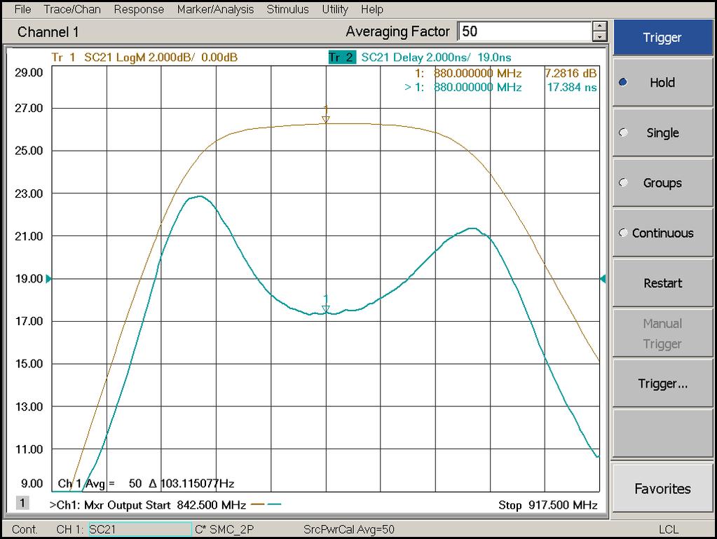
15 Industry-Leading Accuracy with Advanced Calibration Techniques for Testing Mixers and Converters Conversion loss and match Simple setup with no external signal source Match correction Conversion loss, delay, and match USB Reference mixer DUT Power sensor Calibration mixer/filter DUT Scalar Mixer Calibration (SMC) Highest accuracy conversion-loss measurements with simple setup and cal Removes mismatch errors during calibration and measurements by combining one-port and power-meter calibrations Vector Mixer Calibration (VMC) Most accurate measurements of phase and absolute group delay Removes magnitude and phase errors for transmission and reflection measurements by calibrating with characterized through mixer Page 15
16 Testing Mixers and Converters Source 1 OUT 1 OUT 2 Source 2 LO OUT 1 OUT 2 To receivers R1 R3 R4 R2 A C D B Test port 1 Test port 3 Test port 4 Test port 2 DUT Page 16


17 17 PNA Series Innovative Applications Accurate characterization of Mixers and Converters


18 18 PNA-X Series Innovative Applications Measuring Converters with Embedded LOs


19 Noise Figure Measurements with Advanced Error Correction Source-corrected noise figure option extends single-connection multiple-measurement capability of the PNA-X Agilent's unique noise-figurecalibration technique uses an ECal module as an impedance tuner to remove the effects of imperfect system source match Achieve the highest measurement accuracy of any solution on the market frequency Typically four to ten times faster than the NFA Page 19

20 Noise Figure Measurements +28V rear panel RF jumpers Mechanical switch J11 J10 J9 J8 J7 J2 J1 S- parameter receiver + - LO R1 Source 1 OUT 1 OUT 2 Pulse modulator Source 2 OUT 1 OUT 2 Pulse modulator To receivers Noise receivers 10 MHz - 3 GHz GHz A Pulse generators R2 B Noise source used for calibration only Test port 1 Source 2 Output 1 Source 2 Output 2 Test port 2 DUT Impedance tuner for noise figure measurements Page 20

21 N5247A 67 GHz PNA-X 4-Port 10 MHz to 110 GHz Single Sweep System Including: Power leveling True differential Frequency converter measurements Broadband and Banded Page 21

22 Broadband Amplifier Single Sweep Solution 10 MHz to 110 GHz calibrated S-parameters Accurate source power from 10 MHz to 110 GHz Gain compression with 48 db power sweep range at 98 GHz Output spectrum with 77 GHz input signal Page 22


23 Challenges of On-Wafer Device Tests Requires multiple stations to complete tests Probes contact bonding pads multiple times Probes leave marks with each contact Marks with one contact Marks with four contacts Issues: Degraded test accuracy Damaged devices Page 23


24 PNA-X Series for On-Wafer Device Tests Single-contact, multiple-measurements concept minimizes damages on devices All tests are completed with one contact per device Achieve the most accurate characterization Results in easy and reliable wire bonding for improved production yields Page 24

25 World Class Solutions For Terahertz Measurements Banded configuration Page 25
26 NVNA Nonlinear Vector Network Analyzer X-parameters Agilent EEsof EDA Overview Page 26 July 2009
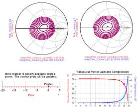
27 How do I optimize desired Amplifier Specifications? PAE (accuracy<3%) Ant Vcc Icc Zo=50ohm Matching Network Matching Network 2W max ACPR (accuracy<1db) VSWR=2.5 max PAE= Power Added Efficiency ACPR= Adjacent Channel Power Ratio VSWR= Voltage Standing Wave Ratio Page 27
28 Nonlinear Component Behavior A 1 A 2 B B 1 2 Page 28
29 X-parameters A 1 A 2 B F ( DC, A, A,..., A, A,...) 1k 1k B F ( DC, A, A,..., A, A,...) 2k 2k B B 1 2 Port Index Harmonic (or carrier) Index The X-parameters provide a mathematically correct mapping of the A and B waves at ports, input powers, harmonics, DC bias, etc, etc. Page 29
30 S-parameters: Linear Measurement, Modeling & Simulation Measure with linear VNA: Small amplitude sinusoids Incident S 21 Transmitted Linear Simulation: Matrix Multiplication S-parameters b1 = S11a1 + S12a2 b2 = S21a1 + S22a2 a 1 S b 11 2 Reflected DUT S 22 Port 1 Port 2 Reflected b 1 a 2 Transmitted S 12 Incident Model Parameters: Simple algebra S ij b a i j a k k 0 j Page 30
31 Scattering Parameters S-Parameters Linear System Description b i S ik a k k b S a S a b S a S a X-Parameters Linear and Nonlinear System Description X X X b ( A ) P ( A ) P a ( A ) ( F ) j ( S ) j l ( T ) j l * ij ij 11 ij, kl 11 kl ij, kl 11 kl kl, (1,1) P a A 11 Large signal drive to the amplifier input port (port #1) at the fundamental frequency (#1) Definitions i = output port index j = output frequency index k = input port index l = input frequency index For example: T X 21,21 Means: output port = 2 output frequency = 1 (fundamental) input port = 2 input frequency = 1 (fundamental) Page 31
 of measured spectra traceable to standards lab Up to 50 GHz of vector corrected bandwidth for time domain")
 during RF")
32 Nonlinear Vector Network Analyzer (NVNA) Vector (amplitude/phase) corrected nonlinear measurements from 10 MHz to 13.5, GHz Calibrated absolute amplitude and relative phase (cross-frequency relative phase) of measured spectra traceable to standards lab Up to 50 GHz of vector corrected bandwidth for time domain waveforms of voltages and currents of DUT Multi-Envelope domain measurements for measurement and analysis of memory effects NVNA FW X-parameters: Extension of Scattering parameters into the nonlinear region providing unique insight into nonlinear DUT behavior X-parameter extraction into ADS nonlinear simulation and design NVNA can control external DC instruments (sweep and sense) during RF measurements New phase calibration standard Standard PNA-X with New Nonlinear features and capability Page 32

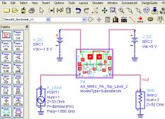

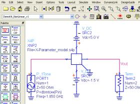
33 Measurement-Based Modeling & Design Flow Measure X-parameters with Agilent s NVNA Design and simulate with measured or generated X- parameters in ADS Design with measured X-parameters in ADS Page 33
34 X-Parameters Does for nonlinear design what S-parameters do for linear design Page 34


35 Atomic Force Microscopy / Scanning Microwave Microscope -SMM is a near field system. The resolution is determined by the Electric field interaction area with the sample. This is on the order of 5-10 nm -SMM uses a network analyzer to measure the vector reflection coefficient caused by the tip-sample interaction; this gives information about the material properties (dielectric properties) -While an AFM needs contact to make a measurement the SMM can measure without contact. You can be 1-10 nm away from the sample and still have good sensitivity 5400 AFM 5 nm Tip/sample interaction area Nosecone assembly Applying cantilever to substrate holder Cantilever, tip, and sample Page 35


36 APPLICATIONS OF SMM Agilent EMG Customers Powerful for semiconductor applications Topography Agilent LSCA Customers Generating excitement amongst life scientists Topography 10 x 10 um Dopant conc n Transistor Images Image of virus particles selectively attached to gold pattern Microwav EMG Electronic Test & Measurement LSCA Life Sciences & Chemical Analysis Page 36


37 SMM: SCANNING MICROWAVE MICROSCOPE Standard AFM New SNMM Scanning nearfield microwave microscope See what s never been seen before! World s most sensitive capacitance measurement with 5nm resolution and farad sensitivity; enables depth profiling of subsurface structures: doping, layers etc. by simultaneous depletion voltage application and uw measurement Page 37

38 Leverage Your Investment to a Wide Range of Applications Amplifier Test Single Connection: Gain compression, IMD, noise figure, harmonics, true differential, PAE, hot S 22 Antenna Test T/R Module Test Pulsed RF and DC Mm-wave Mixer Test NVNA Component characterization X-parameter extraction Pulse envelope domain 750 GHz & beyond! 325 GHz 110 GHz 67 GHz 50 GHz 43.5 GHz 26.5 GHz 13.5 GHz Materials Measurements Signal Integrity Load pull Noise parameters Scanning Microscope Page 38


39 Page 39
How do I optimize desired Amplifier Specifications?
 How do I optimize desired Amplifier Specifications? PAE (accuracy
Millimeter Signal Measurements: Techniques, Solutions and Best Practices
 New Network Analyzer platform Millimeter Signal Measurements: Techniques, Solutions and Best Practices Phase Noise measurements update 1 N522XA PNA Series Network Analyzer Introducing Highest Performance
PNA Family Microwave Network Analyzers (N522x/3x/4xB) CONFIGURATION GUIDE
 CONFIGURATION GUIDE") PNA Family Microwave Network Analyzers (N522x/3x/4xB) CONFIGURATION GUIDE Table of Contents PNA Family Network Analyzer Configurations... 05 Test set and power configuration options...05 Hardware options...
PNA Family Microwave Network Analyzers (N522x/3x/4xB) CONFIGURATION GUIDE Table of Contents PNA Family Network Analyzer Configurations... 05 Test set and power configuration options...05 Hardware options...
Keysight Technologies Nonlinear Vector Network Analyzer (NVNA) Breakthrough technology for nonlinear vector network analysis from 10 MHz to 67 GHz
 Breakthrough technology for nonlinear vector network analysis from 10 MHz to 67 GHz") Keysight Technologies Nonlinear Vector Network Analyzer (NVNA) Breakthrough technology for nonlinear vector network analysis from 1 MHz to 67 GHz 2 Keysight Nonlinear Vector Network Analyzer (NVNA) - Brochure
Keysight Technologies Nonlinear Vector Network Analyzer (NVNA) Breakthrough technology for nonlinear vector network analysis from 1 MHz to 67 GHz 2 Keysight Nonlinear Vector Network Analyzer (NVNA) - Brochure
Configuration of PNA-X, NVNA and X parameters
 Configuration of PNA-X, NVNA and X parameters VNA 1. S-Parameter Measurements 2. Harmonic Measurements NVNA 3. X-Parameter Measurements Introducing the PNA-X 50 GHz 43.5 GHz 26.5 GHz 13.5 GHz PNA-X Agilent
Agilent PNA-X Series Microwave Network Analyzers
 Agilent PNA-X Series Microwave Network Analyzers Reach for unrivaled excellence 1 Choose the leader in network analysis Industry s Most Advanced RF Test Solution Reach for unrivaled excellence The PNA-X
Microwave Network Analyzers PNA-X Series BROCHURE
 Microwave Network Analyzers PNA-X Series BROCHURE Industry s Most Advanced RF Test Solution Reach for unrivaled excellence Choose the leader in network analysis The PNA-X Series of microwave network analyzers
New Ultra-Fast Noise Parameter System... Opening A New Realm of Possibilities in Noise Characterization
 New Ultra-Fast Noise Parameter System... Opening A New Realm of Possibilities in Noise Characterization David Ballo Application Development Engineer Agilent Technologies Gary Simpson Chief Technology Officer
5 ESSENTIAL HINTS TO IMPROVE Millimeter-wave Network Analysis
 5 ESSENTIAL HINTS TO IMPROVE Millimeter-wave Network Analysis Contents 5 Essential Hints to Improve Millimeter-wave Network Analysis Ensure Accurate, Repeatable Results Go to Hint 1 > Calibrate for Better
Keysight Technologies PNA-X Series Microwave Network Analyzers
 Keysight Technologies PNA-X Series Microwave Network Analyzers Active-Device Characterization in Pulsed Operation Using the PNA-X Application Note Introduction Vector network analyzers (VNA) are the common
Agilent Nonlinear Vector Network Analyzer (NVNA)
") Agilent Nonlinear Vector Network Analyzer (NVNA) Breakthrough technology for nonlinear vector network analysis from 1 MHz to 67 GHz I know my amplifier gain is changing with output match, but Hot S22 measurements
Agilent Nonlinear Vector Network Analyzer (NVNA) Breakthrough technology for nonlinear vector network analysis from 1 MHz to 67 GHz I know my amplifier gain is changing with output match, but Hot S22 measurements
Pulsed VNA Measurements:
 Pulsed VNA Measurements: The Need to Null! January 21, 2004 presented by: Loren Betts Copyright 2004 Agilent Technologies, Inc. Agenda Pulsed RF Devices Pulsed Signal Domains VNA Spectral Nulling Measurement
Experiment 12 - Measuring X-Parameters Using Nonlinear Vector Netowrk Analyzer
 ECE 451 Automated Microwave Measurements Laboratory Experiment 12 - Measuring X-Parameters Using Nonlinear Vector Netowrk Analyzer 1 Introduction In this experiment, rstly, we will be measuring X-parameters
Agilent PNA-X Series Microwave Network Analyzers. Complete linear and nonlinear component characterization in a single instrument
 Agilent PNA-X Series Microwave Network Analyzers Complete linear and nonlinear component characterization in a single instrument Choose the leader in network analysis Industry s Most Advanced RF Test Solution
Keysight Technologies PNA and PNA-L Series Microwave Network Analyzers
 Ihr Spezialist für Mess- und Prüfgeräte Keysight Technologies PNA and PNA-L Series Microwave Network Analyzers The standard in microwave network analysis datatec Ferdinand-Lassalle-Str. 52 72770 Reutlingen
Agilent PNA and PNA-L Series Microwave Network Analyzers. The standard in microwave network analysis
 Agilent PNA and PNA-L Series Microwave Network Analyzers The standard in microwave network analysis PNA Family Sets the Standard for Microwave Network Analysis Choose the leader The PNA family builds on
Keysight Technologies PNA-X Series Microwave Network Analyzers
 Keysight Technologies PNA-X Series Microwave Network Analyzers 02 Keysight PNA-X Series Microwave Network Analyzers - Brochure Industry s Most Advanced RF Test Solution Reach for unrivaled excellence Choose
X-Parameters with Active and Hybrid Active Load Pull
 X-Parameters with Active and Hybrid Active Load Pull Gary Simpson, CTO Maury Microwave EuMW 2012 www.maurymw.com 1 General Load Pull Overview 2 Outline 1. Introduction to Maury Microwave 2. Basics and
Platform Migration 8510 to PNA. Graham Payne Application Engineer Agilent Technologies
 Platform Migration 8510 to PNA Graham Payne Application Engineer Agilent Technologies We set the standard... 8410 8510 When we introduced the 8510, we changed the way S-parameter measurements were made!
Agilent PNA Family Microwave Network Analyzers
 gilent PN Family Microwave Network nalyzers Configuration Guide This configuration guide describes standard configurations, options, accessories, upgrade kits and compatible peripherals for the PN Family
Keysight Technologies PNA Family Microwave Network Analyzers
 Keysight Technologies PN Family Microwave Network nalyzers (N522x/3x/4x) Configuration Guide The -models of the PN family (N522x/3x/4x) will be discontinued June 2019. Their -model replacements are available
Keysight Technologies PNA Microwave Network Analyzers The standard in microwave network analysis
 Keysight Technologies PNA Microwave Network Analyzers The standard in microwave network analysis Welcome to the world of PNAs The most popular microwave network analyzers The PNA family builds on Keysight
Power Amplifier Design Utilizing the NVNA and X-parameters
 IMS2011 Power Amplifier Design Utilizing the NVNA and X-parameters Loren Betts 1, Dylan T. Bespalko 2, Slim Boumaiza 2 1 Agilent Technologies, Santa Rosa CA, USA 2 University of Waterloo, Waterloo ON,
Keysight Technologies Making Accurate Intermodulation Distortion Measurements with the PNA-X Network Analyzer, 10 MHz to 26.5 GHz
 Keysight Technologies Making Accurate Intermodulation Distortion Measurements with the PNA-X Network Analyzer, 10 MHz to 26.5 GHz Application Note Overview This application note describes accuracy considerations
Large-Signal Measurements Going beyond S-parameters
 Large-Signal Measurements Going beyond S-parameters Jan Verspecht, Frans Verbeyst & Marc Vanden Bossche Network Measurement and Description Group Innovating the HP Way Overview What is Large-Signal Network
RF and Microwave Test and Design Roadshow 5 Locations across Australia and New Zealand
 RF and Microwave Test and Design Roadshow 5 Locations across Australia and New Zealand Advanced VNA Measurements Agenda Overview of the PXIe-5632 Architecture SW Experience Overview of VNA Calibration
A True Differential Millimeter Wave System with Port Power Control. Presented by: Suren Singh
 A True Differential Millimeter Wave System with Port Power Control Presented by: Suren Singh Agenda Need for True Differential and RF Power Control Vector Network Analyzer RF Port Power Control Port Power
Network Analysis Basics
 Adolfo Del Solar Application Engineer adolfo_del-solar@agilent.com MD1010 Network B2B Agenda Overview What Measurements do we make? Network Analyzer Hardware Error Models and Calibration Example Measurements
Advanced Test Equipment Rentals ATEC (2832) Agilent 8510 System Solutions
 Agilent 8510 System Solutions") E stablished 1981 Advanced Test Equipment Rentals www.atecorp.com 800-404-ATEC (2832) Agilent 8510 System Solutions Your bridge to the future Application guide The guide below shows Agilent Technologies
E stablished 1981 Advanced Test Equipment Rentals www.atecorp.com 800-404-ATEC (2832) Agilent 8510 System Solutions Your bridge to the future Application guide The guide below shows Agilent Technologies
Direct-Conversion I-Q Modulator Simulation by Andy Howard, Applications Engineer Agilent EEsof EDA
 Direct-Conversion I-Q Modulator Simulation by Andy Howard, Applications Engineer Agilent EEsof EDA Introduction This article covers an Agilent EEsof ADS example that shows the simulation of a directconversion,
Expanding Impedance Measurement to Nanoscale:
 Expanding Impedance Measurement to Nanoscale: Coupling the Power of Scanning Probe Microscopy with Performance Network Analyzer (PNA) Hassan Tanbakuchi Senior Research Scientist Agilent Technologies Agilent
Agilent PNA Microwave Network Analyzers
 Agilent PNA Microwave Network Analyzers Application Note 1408-3 Improving Measurement and Calibration Accuracy using the Frequency Converter Application Table of Contents Introduction................................................................2
Fast, Simple, Accurate Applies to Mixers Too
 Fast, Simple, Accurate Applies to Mixers Too Joel Dunsmore, Ph.D. Agilent Fellow Component Test Division R&D 1 2013 Agilent Technologies All-in-one Measurement Systems SCMM Performs S-parameter, IMD, Gain
Load Pull with X-Parameters A New Paradigm for Modeling and Design
 Load Pull with X-Parameters A New Paradigm for Modeling and Design Gary Simpson, CTO Maury Microwave Anaheim, May 2010 For a more detailed version of this presentation, go to www.maurymw.com/presentation.htm
AV3672 Series Vector Network Analyzer
 AV3672 Series Vector Network Analyzer AV3672A/B/C/D/E (10MHz 13.5 GHz/26.5 GHz/43.5 GHz/50 GHz/67 GHz) Product Overview: AV3672 series vector network analyzer include AV3672A (10MHz 13.5GHz), AV3672B (10MHz
Agilent Network Analyzer Selection Guide
 Agilent Network Analyzer Selection Guide Please note: This document does not contain Agilent s most up-to-date network analyzer portfolio. This document is available for reference only for customers using
Advanced Test Equipment Rentals ATEC (2832)
") Established 1981 Advanced Test Equipment Rentals www.atecorp.com 800-404-ATEC (2832) Agilent 2-Port and 4-Port PNA-X Network Analyzer N5249A - 10 MHz to 8.5 GHz N5241A - 10 MHz to 13.5 GHz N5242A - 10
Established 1981 Advanced Test Equipment Rentals www.atecorp.com 800-404-ATEC (2832) Agilent 2-Port and 4-Port PNA-X Network Analyzer N5249A - 10 MHz to 8.5 GHz N5241A - 10 MHz to 13.5 GHz N5242A - 10
Microwave & RF Device Characterization Solutions
 Microwave & RF Device Characterization Solutions MT2000 Mixed-Signal Active Load Pull System (1.0 MHz to 40.0 GHz) And MT2001 System Software From Powered by Maury Microwave is ISO: 9001:2008/AS9100C Certified.
Measurements 2: Network Analysis
 Measurements 2: Network Analysis Fritz Caspers CAS, Aarhus, June 2010 Contents Scalar network analysis Vector network analysis Early concepts Modern instrumentation Calibration methods Time domain (synthetic
MT1000 and MT2000 Mixed-Signal Active Load Pull System (1.0 MHz to 40.0 GHz) And MT2001 System Software
 And MT2001 System Software") MT1000 and MT0 Mixed-Signal Active Load Pull System (1.0 MHz to 40.0 GHz) And MT1 System Software DATA SHEET / 4T-097 U.S. Patent No. 8,456,175 B2 Several international patents also available // SEPTEMBER
MT1000 and MT0 Mixed-Signal Active Load Pull System (1.0 MHz to 40.0 GHz) And MT1 System Software DATA SHEET / 4T-097 U.S. Patent No. 8,456,175 B2 Several international patents also available // SEPTEMBER
Efficiently simulating a direct-conversion I-Q modulator
 Efficiently simulating a direct-conversion I-Q modulator Andy Howard Applications Engineer Agilent Eesof EDA Overview An I-Q or vector modulator is a commonly used integrated circuit in communication systems.
Keysight Technologies Amplifier and CW Swept Intermodulation - Distortion Measurements using the PNA Microwave Network Analyzers.
 Keysight Technologies Amplifier and CW Swept Intermodulation - Distortion Measurements using the PNA Microwave Network Analyzers Application Note Introduction This application note covers testing of an
9 khz to 4.5/6.5/8.5 GHz 100 khz to 4.5/6.5/8.5 GHz (with bias tees) 300 khz to 14/20 GHz (with bias tees)
 300 khz to 14/20 GHz (with bias tees)") Agilent E5071C ENA Network Analyzer 9 khz to 4.5/6.5/8.5 GHz 100 khz to 4.5/6.5/8.5 GHz () 300 khz to 14/20 GHz () The industry standard in RF network analysis ENA New Standards in Speed, Accuracy and
Agilent E5071C ENA Network Analyzer 9 khz to 4.5/6.5/8.5 GHz 100 khz to 4.5/6.5/8.5 GHz () 300 khz to 14/20 GHz () The industry standard in RF network analysis ENA New Standards in Speed, Accuracy and
S3602A/B Vector Network Analyzer Datasheet
 S3602A/B Vector Network Analyzer Datasheet Saluki Technology Inc. The document applies to the vector network analyzers of the following models: S3602A vector network analyzer (10MHz-13.5GHz). S3602B vector
Vector Network Analysis
 Portfolio Brochure Vector Network Analysis Product Portfolio Vector Network Analysis VNA Innovation Timeline In 1965, Anritsu filed the patent that defined the first modern Vector Network Analyzer (VNA).
Overcoming Mixer Measurement Challenges
 Overcoming Mixer Measurement Challenges October 10, 2002 presented by: Robb Myer Dave Ballo Today we will be looking at overcoming measurements challenges associated with frequency translating devices
LB680A Pulse Profiling USB PowerSensor+ Data Sheet
 Key PowerSensor+ Specifications 50 MHz to 20 GHz - 40 dbm to +20 dbm 2.8% Total Error* 1.20:1 VSWR (-21 db Return Loss) * Measuring a well matched DUT (-20 dbm @ 2 GHz) Measurement Capability Time Gated
Agilent Network Analyzer Selection Guide
 Agilent Network Analyzer Selection Guide Network Analyzers to Meet Your Needs Agilent offers a variety of network analyzers with the frequency, performance, and versatility to meet your measurement needs.
Compact Series: S5065 & S5085 Vector Network Analyzers KEY FEATURES
 Compact Series: S5065 & S5085 Vector Network Analyzers KEY FEATURES Frequency range: 9 khz - 6.5 or 8.5 GHz Measured parameters: S11, S12, S21, S22 Wide output power adjustment range: -50 dbm to +5 dbm
PLANAR S5048 and TR5048
 PLANAR S5048 and TR5048 Vector Network Analyzers KEY FEATURES Frequency range: 20 khz 4.8 GHz COM/DCOM compatible for LabView Measured parameters: and automation programming S11, S12, S21, S22 (S5048)
What s inside. Highlights. Welcome. Mixer test third in a series. New time-domain technique for measuring mixer group delay
 What s inside 2 New time-domain technique for measuring mixer group delay 3 Uncertainty in mixer group-delay measurements 5 Isolation a problem? Here s how to measure mixer group delay 6 Low-power mixer
Large-Signal Network Analysis Technology for HF analogue and fast switching components
 Large-Signal Network Analysis Technology for HF analogue and fast switching components Applications This slide set introduces the large-signal network analysis technology applied to high-frequency components.
A Simplified Extension of X-parameters to Describe Memory Effects for Wideband Modulated Signals
 Jan Verspecht bvba Mechelstraat 17 B-1745 Opwijk Belgium email: contact@janverspecht.com web: http://www.janverspecht.com A Simplified Extension of X-parameters to Describe Memory Effects for Wideband
Vector Network Analyzer
 Vector Network Analyzer VNA Basics VNA Roadshow Budapest 17/05/2016 Content Why Users Need VNAs VNA Terminology System Architecture Key Components Basic Measurements Calibration Methods Accuracy and Uncertainty
PLANAR 814/1. Vector Network Analyzer
 PLANAR 814/1 Vector Network Analyzer Frequency range: 100 khz 8 GHz Measured parameters: S11, S12, S21, S22 Wide output power range: -60 dbm to +10 dbm >150 db dynamic range (1 Hz IF bandwidth) Direct
Fast and Accurate Simultaneous Characterization of Signal Generator Source Match and Absolute Power Using X-Parameters.
 Fast and Accurate Simultaneous Characterization of Signal Generator Source Match and Absolute Power Using X-Parameters. April 15, 2015 Istanbul, Turkey R&D Principal Engineer, Component Test Division Keysight
Agilent PNA Microwave Network Analyzers
 Agilent PNA Microwave Network Analyzers Application Note 1408-1 Mixer Transmission Measurements Using The Frequency Converter Application Introduction Frequency-converting devices are one of the fundamental
EXTEND YOUR REACH. Copper Mountain Technologies USB VNAs. S-parameter measurement solutions from 9 khz to 110 GHz Measured parameters from S 11
 Copper Mountain Technologies USB VNAs S-parameter measurement solutions from 9 khz to 110 GHz Measured parameters from S 11 to S 44 Dynamic range as high as 162 db typ. (1 Hz IF bandwidth) Measurement
Scanning Microwave. Expanding Impedance Measurements to the Nanoscale: Coupling the Power of Scanning Probe Microscopy with the PNA
 Agilent Technologies Scanning Microwave Microscopy (SMM) Expanding Impedance Measurements to the Nanoscale: Coupling the Power of Scanning Probe Microscopy with the PNA Presented by: Craig Wall PhD Product
Traceability and Modulated-Signal Measurements
 Traceability and Modulated-Signal Measurements Kate A. Remley 1, Dylan F. Williams 1, Paul D. Hale 2 and Dominique Schreurs 3 1. NIST Electromagnetics Division 2. NIST Optoelectronics Division 3. K.U.
Keysight Technologies Accurate Mixer Measurements Using the ENA RF Networks Analyzers Frequency-Offset Mode. Application Note
 Keysight Technologies Accurate Mixer Measurements Using the ENA RF Networks Analyzers Frequency-Offset Mode Application Note 1 Measurement Parameters of the Mixer The ENA FOM offers two advanced mixer
Keysight 2-Port and 4-Port PNA-X Network Analyzer
 Keysight 2-Port and 4-Port PNA-X Network Analyzer N5249A - 0 MHz to 8.5 GHz N524A - 0 MHz to 3.5 GHz N5242A - 0 MHz to 26.5 GHz Data Sheet and Technical Specifications Documentation Warranty THE MATERIAL
Compact Series: S5048 & TR5048 Vector Network Analyzers KEY FEATURES
 Compact Series: S5048 & TR5048 Vector Network Analyzers KEY FEATURES Frequency range: 20 khz - 4.8 GHz Measured parameters: S11, S12, S21, S22 (S5048) S11, S21 (TR5048) Wide output power adjustment range:
IMD Measurement Wizard for the E5072A ENA Series Network Analyzer Operation Manual. Agilent Technologies June 2012
 IMD Measurement Wizard for the E5072A ENA Series Network Analyzer Operation Manual Agilent Technologies June 2012 1 Important Notice Notices The information contained in this document is subject to change
print close Chris Bean, AWR Group, NI
 1 of 12 3/28/2016 2:42 PM print close Microwaves and RF Chris Bean, AWR Group, NI Mon, 2016-03-28 10:44 The latest version of an EDA software tool works directly with device load-pull data to develop the
Hot S 22 and Hot K-factor Measurements
 Application Note Hot S 22 and Hot K-factor Measurements Scorpion db S Parameter Smith Chart.5 2 1 Normal S 22.2 Normal S 22 5 0 Hot S 22 Hot S 22 -.2-5 875 MHz 975 MHz -.5-2 To Receiver -.1 DUT Main Drive
Improving Amplitude Accuracy with Next-Generation Signal Generators
 Improving Amplitude Accuracy with Next-Generation Signal Generators Generate True Performance Signal generators offer precise and highly stable test signals for a variety of components and systems test
Advanced Test Equipment Rentals ATEC (2832)
") Established 1981 Advanced Test Equipment Rentals www.atecorp.com 800-404-ATEC (2832) Agilent E5071C ENA Network Analyzer 9 khz to 4.5/6.5/8.5 GHz 100 khz to 4.5/6.5/8.5 GHz () 300 khz to 14/20 GHz () The
Established 1981 Advanced Test Equipment Rentals www.atecorp.com 800-404-ATEC (2832) Agilent E5071C ENA Network Analyzer 9 khz to 4.5/6.5/8.5 GHz 100 khz to 4.5/6.5/8.5 GHz () 300 khz to 14/20 GHz () The
Introduction. Part 1. Introduction...2
 Keysight Technologies Simple Scalar Network Analysis of Frequency Converter Devices using the U2000 USB Power Sensor Series with the ENA Network Analyzer Application Note Introduction This application
Understanding RF and Microwave Analysis Basics
 Understanding RF and Microwave Analysis Basics Kimberly Cassacia Product Line Brand Manager Keysight Technologies Agenda µw Analysis Basics Page 2 RF Signal Analyzer Overview & Basic Settings Overview
HP Archive. This vintage Hewlett Packard document was preserved and distributed by www. hparchive.com Please visit us on the web!
 HP Archive This vintage Hewlett Packard document was preserved and distributed by www. hparchive.com Please visit us on the web! On-line curator: Glenn Robb This document is for FREE distribution only!
Keysight Technologies Scanning Microwave Microscope Mode. Application Note
 Keysight Technologies Scanning Microwave Microscope Mode Application Note Introduction Measuring electromagnetic properties of materials can provide insight into applications in many areas of science and
Keysight Technologies Network Analyzer Measurements: Filter and Amplifier Examples. Application Note
 Keysight Technologies Network Analyzer Measurements: Filter and Amplifier Examples Application Note Introduction Both the magnitude and phase behavior of a component are critical to the performance of
Banded Milimeter Wave Network Analysis TECHNICAL OVERVIEW
 Banded Milimeter Wave Network Analysis TECHNICAL OVERVIEW Banded Measurement Solutions to 1.5 THz Keysight offers a variety of banded millimeter-wave solutions that enable the PNA/ PNA-X network analyzers
Narrow Pulse Measurements on Vector Network Analyzers
 Narrow Pulse Measurements on Vector Network Analyzers Bert Schluper Nearfield Systems Inc. Torrance, CA, USA bschluper@nearfield.com Abstract - This paper investigates practical aspects of measuring antennas
LB480A Pulse Profiling USB PowerSensor+ Data Sheet
 Key PowerSensor+ Specifications 50 MHz to 8 GHz (functional to 10 GHz) - 60 dbm to +20 dbm 1.95% Total Error* 1.09:1 VSWR (-27 db Return Loss) * Measuring a well matched DUT (-20 dbm @ 1 GHz) No Zero No
Keysight Technologies PNA and PNA-L Series Microwave Network Analyzers
 Ihr Spezialist für Mess- und Prüfgeräte Keysight Technologies PNA and PNA-L Series Microwave Network Analyzers The standard in microwave network analysis PNA Family Sets the Standard for Microwave Network
MAKING TRANSIENT ANTENNA MEASUREMENTS
 MAKING TRANSIENT ANTENNA MEASUREMENTS Roger Dygert, Steven R. Nichols MI Technologies, 1125 Satellite Boulevard, Suite 100 Suwanee, GA 30024-4629 ABSTRACT In addition to steady state performance, antennas
Agilent Network Analyzer Selection Guide
 Agilent Network Analyzer Selection Guide Network Analyzers to Meet Your Needs Agilent offers a variety of network analyzers with the frequency, performance, and versatility to meet your measurement needs.
Agilent Technologies Noise Figure Selection Guide
 Agilent Technologies Noise Figure Selection Guide Minimize the Noise 1958 1960 1970 1980 1990 2000 2008 50 Years of Noise Figure Leadership from Agilent Technologies Table of Contents Noise Figure Overview...2
LB480A Pulse Profiling USB PowerSensor+ Data Sheet
 Key PowerSensor+ Specifications 100 MHz to 8 GHz (functional to 10 GHz) -60 dbm to +20 dbm 1.95% Total Error* 1.09:1 VSWR (-27 db Return Loss) * Measuring a well matched DUT (-20 dbm @ 1 GHz) Measurement
A 600 GHz Varactor Doubler using CMOS 65nm process
 A 600 GHz Varactor Doubler using CMOS 65nm process S.H. Choi a and M.Kim School of Electrical Engineering, Korea University E-mail : hyperleonheart@hanmail.net Abstract - Varactor and active mode doublers
Introduction. Part 1. Introduction...2
 Keysight Technologies Simple Scalar Network Analysis of Frequency Converter Devices using the U2000 USB Power Sensor Series with the ENA Network Analyzer Application Note Introduction This application
Agilent 2-Port and 4-Port PNA-X Network Analyzer. N5241A - 10 MHz to 13.5 GHz N5242A - 10 MHz to 26.5 GHz Data Sheet and Technical Specifications
 Agilent 2-Port and 4-Port PNA-X Network Analyzer N5241A - 10 MHz to 13.5 GHz N5242A - 10 MHz to 26.5 GHz Data Sheet and Technical Specifications Documentation Warranty THE MATERIAL CONTAINED IN THIS DOCUMENT
S3602C Vector Network Analyzer Datasheet
 S3602C Vector Network Analyzer Datasheet Saluki Technology Inc. The document applies to the vector network analyzers of the following models: S3602C vector network analyzer (10MHz - 43.5GHz). Options of
Fundamentals of RF Design RF Back to Basics 2015
 Fundamentals of RF Design 2015 Updated January 1, 2015 Keysight EEsof EDA Objectives Review Simulation Types Understand fundamentals on S-Parameter Simulation Additional Linear and Non-Linear Simulators
Keysight Technologies Pulsed Antenna Measurements Using PNA Network Analyzers
 Keysight Technologies Pulsed Antenna Measurements Using PNA Network Analyzers White Paper Abstract This paper presents advances in the instrumentation techniques that can be used for the measurement and
Keysight M9485A PXIe Multiport Vector Network Analyzer
 Keysight M9485A PXIe Multiport Vector Network Analyzer 02 Keysight M9485A PXIe Multiport Vector Network Analyzer - Brochure High-Performance PXI Multiport Vector Network Analyzer (VNA) Innovative solution
Vector Network Analyzer Application note
 Vector Network Analyzer Application note Version 1.0 Vector Network Analyzer Introduction A vector network analyzer is used to measure the performance of circuits or networks such as amplifiers, filters,
Agilent Antenna and RCS Measurement Configurations Using PNA Microwave Network Analyzers. White Paper
 Agilent Antenna and RCS Measurement Configurations Using PNA Microwave Network Analyzers White Paper Abstract As technology changes, new and different techniques for measuring and characterizing antenna
772D coaxial dual-directional coupler 773D coaxial directional coupler. 775D coaxial dual-directional coupler 776D coaxial dual-directional coupler
 72 772D coaxial dual-directional coupler 773D coaxial directional coupler 775D coaxial dual-directional coupler 776D coaxial dual-directional coupler 777D coaxial dual-directional coupler 778D coaxial
QUICK START GUIDE FOR DEMONSTRATION CIRCUIT 678A 40MHZ TO 900MHZ DIRECT CONVERSION QUADRATURE DEMODULATOR
 DESCRIPTION QUICK START GUIDE FOR DEMONSTRATION CIRCUIT 678A LT5517 Demonstration circuit 678A is a 40MHz to 900MHz Direct Conversion Quadrature Demodulator featuring the LT5517. The LT 5517 is a direct
PLANAR 804/1. Vector Network Analyzer
 PLANAR 804/1 Vector Network Analyzer Frequency range: 100 khz 8 GHz Measured parameters: S11, S12, S21, S22 Wide output power range: -60 dbm to +10 dbm >145 db dynamic range (1 Hz IF bandwidth) Time domain
A New Noise Parameter Measurement Method Results in More than 100x Speed Improvement and Enhanced Measurement Accuracy
 MAURY MICROWAVE CORPORATION March 2013 A New Noise Parameter Measurement Method Results in More than 100x Speed Improvement and Enhanced Measurement Accuracy Gary Simpson 1, David Ballo 2, Joel Dunsmore
Measurements with Scattering Parameter By Joseph L. Cahak Copyright 2013 Sunshine Design Engineering Services
 Measurements with Scattering Parameter By Joseph L. Cahak Copyright 2013 Sunshine Design Engineering Services Network Analyzer Measurements In many RF and Microwave measurements the S-Parameters are typically
Agilent Millimeter-Wave Network Analyzers 10 MHz to 110 GHz, with Extensions to 1.1 THz. Technical Overview
 Agilent Millimeter-Wave Network Analyzers 10 MHz to 110 GHz, with Extensions to 1.1 THz Technical Overview Single Sweep 10 MHz to 110 GHz Measurement Solutions Currently there are two solutions that offer
THz Vector Network Analyzer Development & Measurements
 THz Vector Network Analyzer Development & Measurements Jeffrey L Hesler, Yiwei Duan, Brian Foley and Thomas Crowe Virginia Diodes Inc., Charlottesville, VA, USA Abstract: Virginia Diodes has been developing
GET10B Radar Measurement Basics- Spectrum Analysis of Pulsed Signals. Copyright 2001 Agilent Technologies, Inc.
 GET10B Radar Measurement Basics- Spectrum Analysis of Pulsed Signals Copyright 2001 Agilent Technologies, Inc. Agenda: Power Measurements Module #1: Introduction Module #2: Power Measurements Module #3:
Test & Calibration Benefits from a New Precision RF/Microwave Calibrator
 Test & Calibration Benefits from a New Precision RF/Microwave Calibrator Topics: RF & Microwave calibration signal requirements Design philosophy and architecture of the new RF Calibrator. Spectrum analyzer
Optoelectronic Components Testing with a VNA(Vector Network Analyzer) VNA Roadshow Budapest 17/05/2016
 VNA Roadshow Budapest 17/05/2016") Optoelectronic Components Testing with a VNA(Vector Network Analyzer) VNA Roadshow Budapest 17/05/2016 Content Introduction Photonics & Optoelectronics components Optical Measurements VNA (Vector Network
Optoelectronic Components Testing with a VNA(Vector Network Analyzer) VNA Roadshow Budapest 17/05/2016 Content Introduction Photonics & Optoelectronics components Optical Measurements VNA (Vector Network