INTRO TRAFFIC 101. What is the purpose of a traffic signal? What are the parts that make it work? How do we time a traffic signal?
|
|
|
- Charles Hudson
- 5 years ago
- Views:
Transcription
1 INTRO TRAFFIC 101 What is the purpose of a traffic signal? What are the parts that make it work? How do we time a traffic signal? How do we maintain a traffic signal?
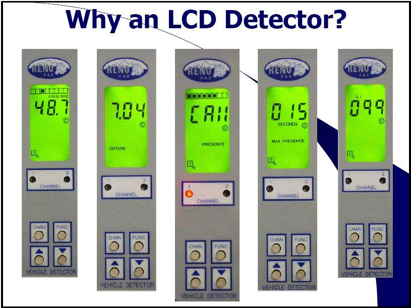
2 What is the purpose of a traffic signal?
3 Ensure safe and orderly flow of traffic Protect pedestrians and vehicles at busy intersections Reduce the severity and frequency of accidents between vehicles entering intersections Safely and efficiently move traffic!
4 When Properly Designed and Located: Allow for orderly traffic (vehicle and non-motorized) flow. Can increase the amount of traffic an intersection is able to handle. Can reduce the crash frequency, particularly right-angle crashes. Can be coordinated for nearly continuous traffic flow along a given route. Can be used to interrupt heavy traffic to permit side traffic to enter or cross a major roadway
5 What makes a traffic signal work?
6 Parts Cabinet & Controller Unit (CU) Controllers run timings programmed by the agency Malfunction Management Unit (MMU) Also called the conflict monitor it is the device used to detect and respond to improper and conflicting signals and improper operating voltages in a traffic control system. Load Switch (LS) Takes the DC signal from the controller and switches it to AC outputs to be sent to the field. Flasher (FL) Similar to a LS in look it simply provides a AC flashing output that can be transferred to the field. Flash Transfer Relay (FTR) Transfers the field indications between either the Load Switch or Flasher. Controlled by the MMU
7 Traffic Signal Heads & Hardware o Housing o Mounting Hardware o Pedestrian Pushbuttons
8 Housing o Vehicle and Pedestrian Signals o Aluminum vs. Polycarbonate (MoDOT) o LED s (Light Emitting Diode s) o Visors and Backplates

9 Aluminum / Polycarbonate Aluminum More expensive Heavier Requires Painting Polycarbonate Less expensive Weighs Less No painting required (standard colors black, green, yellow)

10 LED Indications o 90% power savings over incandescent o Long life (5 year warranty) o Fits in standard 8 and 12 Vehicle housing and 9, 12 and 16 Pedestrian housing o ITE Specifications (GT1)


")
11 Visors and backplates Visors Reduces sun phantom Cuts off side view Available in Aluminum and Polycarbonate Scoop Visor Backplates Provides a solid background Available in Aluminum and Polycarbonate Available Louvered (reduces wind load)
12 Mounting hardware o Pipe Bracketing o Span Wire o Other Mounting Methods
13 Pipe bracketing o MoDOT Signal Bracketing o Side of Post/Pole mount o 1-1/2 pipe fittings o Connects to the top and bottom of signal housing o Bands or bolts with pole plate or hub

14 Span wire o Used on temporary signal systems o Iron or Aluminum o Hangs from cable over intersection o Top has wire entrance and balance adjuster o Bottom connects to a tether for stabilization
15 Other mounting methods o Astro Brac from Pelco o Connects to top and bottom of signal o Attached to mast arm by clamp assembly o Allows signal raising, lowering or rotation o CPI Poly Bracketing o Yellow or Black


16 Pedestrian pushbutton o Campbell Pushbutton o Solid State o Piezo, LED and Audible Tone o Round or Rectangle o Advisor APS o Visual, Tactile and Audible information o Teeco Pushbutton o Mechanical
17 Other Parts Pedestrian Poles Mast Arm Structures Conduit Pull boxes Wire Lighting at Intersection Traffic Signal signing
18 Methods of Detection
19 Today s Options Preformed Loops & LCD Detectors Cut in Place loops Video Radar In Pavement Wireless


20 Preformed Loop & LCD Detectors
21 Why Preformed Loops? Long term reliability Five layers of protection The most accurate sensor Maintains integrity for the life of the pavement Stronger than standard loops Manufactured in a controlled environment Easy to handle, ship, and install Cost effective
22 Manufacture Tested Before that loop leaves Reno it is soaked in Salt Water for three days. The loop is then megged and must exceed 1000 megs.
23
24
25


26 Video Detection The most possible applications Easy to install. If conduit is open to the closest pole to the cabinet we can install Terra in one working day. Easy maintenance. Only a laptop is required to change detection.
27 Terra Technology is Integrated Camera State-of-the-art dual-core processor Adaptive lighting control Embedded web server access for setup & monitoring via standard Internet web browsers Streaming MPEG-4 digital video anywhere, anyhow 3-wires only installation Reduced cabling costs Faster, easier installation ClearVision faceplate for low maintenance Now with HD in the Vision Product
.")
28 Most Common (Intersection)...
29 Typical Installation
30 Radar Detection Freeway / Arterial Management Stop Bar / Presence Detection Advanced Intersection Detection / Queue Management


31 Radar is consistently accurate in all weather conditions Radar is unaffected by: Rain Snow Fog Wind Ice Storms Dust Storms Changes in Lighting Sun Glare Shadowing


32 In-Pavement Wireless Detects Vehicle Presence and movement accurately Flexible and reliable wireless technology Virtually maintenance free Stop bar and advance detection
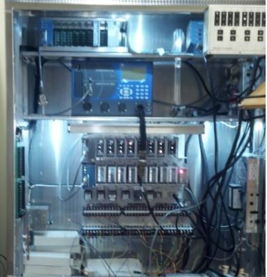
33 Traffic Signal Cabinets
34 NEMA National Electrical Manufacturers Association First Traffic Standard in 1975 (TS1) Defines: Definitions Environmental Controller Monitoring Cabinet Architecture Auxiliary Devices Enclosures
35 Background of TS1 First cabinet standard issued in 1975 TS1 set the MINIMUM requirements for safe and effective traffic equipment. Defined items such as: Controller Operations (MIN GRN) Controller I/O (Ph. Next, Ph. On) Hardware (Connectors, pin outs, ect.)
36 Background of TS2 Approved by NEMA in March 1992 First major update of the TS1 standard issued in TS2 goes above and beyond TS1 by defining controllers, cabinets, and systems more completely.
37 Defined by TS2 Coordination Preemption Time Base Control Automatic Flash Operation Cabinet Hardware Telemetry Signals Detection Controller Logging Output Monitoring AC Power Monitoring
38 Cabinet Layout TS1 TS2 Type 1 TS2 Type 2
39
40
41 TS1
, or D connector.")
42 TS1 Alarm Inputs & Flash Inputs must be wired to TIO,FOI board (Telemetry), or D connector. No CMU data available the controller
43 TS2 Type 1
44 TS2 Alarm Inputs & Flash Inputs come in through BIU s MMU is connected to controller to pass flash data
45 What if I want MMU data and I have a TS1 cabinet??? Buy a TS2 cabinet!!! How about a TS2 Type 2 cabinet modify???

46 TS2 Type 2 -Remove CMU and install a MMU -Add an SDLC cable between Controller and MMU -Option to add a TS2 Detector Rack for full TS2 detectors.
47 SDLC TECHNOLOGY Synchronous Data Link Control Unbalanced/Full Duplex Point to Point or Multipoint 153,600 bps But what does all this mean?
48 Simplified Cabinet Wiring 15 wire SDLC bus replaces 171 wire A, B, and C cables Program Verification Controller and MMU verify each others program every 100msec Redundant MMU Function A TS2 controller can put the intersection into flash if the MMU fails
49 Clearance Time Monitoring The MMU times the interval between conflicting greens and yellow clearance time AC Power Monitoring The MMU monitors incoming power for low voltage and brownout conditions Logging By Controller Detector Report Events Report MMU Report
50 TS2 DETECTION UPGRADES Makes provisions for 64 detectors The TS1 standard only has 8 Detector Health Monitoring Normal Operation Watchdog Failure Open Loop Shorted Loop Excessive Change in Inductance Failed Detectors TS2 detectors ALWAYS fail on and report failure to the controller
51 TS2 cabinet components: Load Switches, Flasher & Flash Transfer Relays Downward-compatible with TS1 TS2 load switch has peak leakage of 10 ma TS2 flasher & flash transfer relay operate at 89 VAC
52 Interfaces detector racks & terminals & facilities to SDLC bus in Type 1 mode 15-pin D connector on front panel to SDLC bus 64-pin DIN connector to backplane I/O includes: 8 inputs TS2 cabinet components: Bus Interface Unit (BIU) 4 opto-isolated inputs 24 remappable input/outputs 15 outputs 4 address select inputs
53 TS2 cabinet components: Understanding BIUs BIU 1: I/O for most 4-phase intersections: 8 load switches, 4 ped pushbuttons, 2 preempt channels... BIU 2: Augments BIU 1 with I/O for most 8-phase intersections BIU 3: Signals used in system applications with remote communication units (RCUs) BIU 4: Seldom-used I/O signals BIUs 9-12: 16 detector channels per BIU, for up to 64 detectors per cabinet BIUs 5-8 & 13-16: Reserved for TS2 & manufacturer use
54 TS2 cabinet components: TS2 Cabinet Power Supply One required per TS2 cabinet with a BIU. Four outputs: 24 VDC to drive load switches & BIUs. 12 VDC to drive TS2 detectors. 12 VAC for isolated inputs. 60 Hz timing reference for BIUs. LED lamp for each output. Fuses for AC power input & power outputs.
55
56
57
58
59
60
61
62 CONTROLLER PROGRAMMING
63 PHASE: Any combination of traffic movements receiving right-of-way simultaneously during one or more intervals Vehicular Phases Pedestrian Phases
64 NO U TURN 1 5 STANDARD NEMA PHASING QUAD CONFIGURATION f8 f3 f2 f5 f1 f6 f7 f4 4 8
65 VEHICLE PHASE 6
66 RING: Consists of one or more sequentially timed, conflicting phases, arranged to time in a preestablished order. BARRIER: A reference point in the preferred sequence of a multi-ring controller at which all rings are interlocked. Barriers assure there will be no concurrent selection and timing of conflicting phases for traffic movements in different rings. All rings cross the barrier simultaneously to select and time phases on the other side.
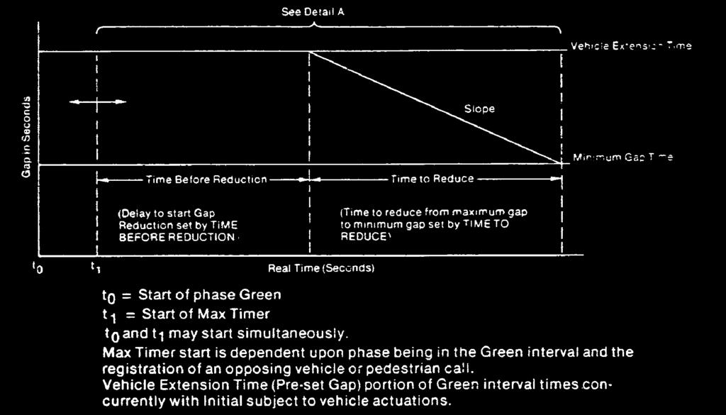
67 RING 1 RING STANDARD NEMA PHASING QUAD CONFIGURATION BARRIER 4 8 BARRIER
68 CONCURRENT GROUPS: All of the phases between two barriers. Typically, they are the left turn and through movements on a single street. PRIORITY GROUPS: Phase Priority assignment which determines the sequence the controller will follow to service calls.
69 STANDARD NEMA PHASING QUAD CONFIGURATION PRIORITY GROUPS RING 1 RING BARRIER CONCURRENT GROUP CONCURRENT GROUP BARRIER
70 INTERVAL: Portions of the time Cycle - VEHICLE MINIMUM GREEN - PEDESTRIAN WALK - PEDESTRIAN CLEARANCE - VEHICLE EXTENSION (PASSAGE) - MAX GREEN (1, 2, OPTIONAL 3) - GREEN REST / GREEN TRANSFER - YELLOW CLEARANCE - RED CLEARANCE
71 CONFIGURATION SUBMENU (MAIN MENU - 1) - RING STRUCTURE - PHASES IN USE - EVENT LOGGING

72 Defines the standard phase sequence R1 R2 CG1 f1 f2 f5 f6 CG2 f3 f4 f7 f8 CG3 f9 f10 f11 f12

73 Defines which phases are active in the sequence R1 R2 CG1 f1 f2 f5 f6 CG2 f3 f4 f7 f8 CG3 f9 f10 f11 f12

74 Specifies which controller events will be logged. As the event occurs, a descriptive message is logged along with the date and time of the occurrence.
75 CONTROLLER SUBMENU (MAIN MENU - 2) - TIMING DATA - RECALL DATA - OVERLAP DATA
76 Defines the timing for all basic phase intervals
77 GREEN INTERVAL OF AN ACTUATED PHASE WITHOUT VOLUME DENSITY Start of Green This point is Based on the Min. Grn. setting This point can occur Between Min Grn period And Maximum in effect Extensible Period Termination Point Max in effect Is based on TOD Manual, or Coord Plan in effect Max 1, 2, or 3 Minimum Green duration Extensible Period Max timers do Not start timing Until there is a Serviceable conflicting call
78 Volume Density: Variable Initial = seconds per actuation X number of actuations. Actuations Before = number of actuations before time is added to min. green Seconds/Actuation = how much time is added when you start adding Max. Initial = how high the Max initial green is allowed to build
79
80 GREEN INTERVAL OF AN ACTUATED PHASE WITH VOLUME DENSITY Min. Initial time Duration established By min. green Time setting This point can Occur between Min. Grn. And Max. Initial period This is the Absolute maximum For the variable Initial period Max in effect Is based on TOD Manual, or Coord Plan in effect Start of Green Minimum Green Time Variable Initial Termination Point Maximum Initial Period Extensible Period Termination Point Max 1, 2, or 3 Min Grn duration Added Initial Variable Initial Period Extensible Period Max timers do Not start timing Until there is a Serviceable conflicting call
81 Remembers a vehicle call Even after the vehicle has Left the detection zone Places a call when the phase is not GREEN Places a ped call when the phase is not in WALK Same as VEHICLE RECALL + keeps the phase GREEN for the MAX time Places a call on the phase in the absence of any calls Defines calls that the controller will place internally (in addition to or in place of calls placed by vehicle / pedestrian detectors)
82 OVERLAP: A traffic movement timed concurrently with one or more phases (parent phases). Typically the yellow and red clearance timing of the overlap is equal to that of the phase terminating the overlap.
83 NO U TURN ASC/2S Features: f6 f1 f8-12 Phases - 2 Rings - 4 Overlaps *** f7 f3 f4 OLAP A = f2 + f 3 f5 f2 *** The 12 phases can also be programmed as basic overlaps

84 VEHICLE PHASE 2 OLAP A f2 + f3 PEDESTRIAN PHASE 2
85 NO U TURN ASC/2S Features: f6 f1 f8-12 Phases - 2 Rings - 4 Overlaps *** f7 f3 f4 OLAP A = f2 + f 3 f5 f2 *** The 12 phases can also be programmed as basic overlaps
86 Defines phases that overlaps can time with and any modified overlap operation (e.g. protected/permissive, lag)
87 COORDINATION
88 COORDINATION: The control or platooning of traffic to permit a continuous flow of vehicles along a street at a designed speed.
89 COORDINATION (MM- 3) Establishes a timing plan for the intersection which results in some form of progression in an arterial system.
90 CYCLE: The time required for one complete revolution of the timing dial or one complete sequence of signal indications. 100 SEC CYCLE LENGTH f 1&5 f 4&8 f 2&6 f 3&7

91 Offset = A value calculated for vehicle travel time from a reference intersection Offset = distance between intersections / travel speed Offset Reference Point = typically start of coordinated phase green interval (user programmable)
92 1st St. 2nd St. TRAVEL TIME = DISTANCE / SPEED = ((.25 MILES) / (35 MPH)) X (3600 SEC/HR) = SEC (round up to 26 SEC) 1/4 mile Main St. (35 MPH)
93 SPLIT: The portion of the cycle length allocated to each phase in the intersection (green + yellow + red). f4 f7 f6 f1 f3 f8 Split times can be expressed in percent (%) or seconds ( ). f5 f2
94 1 sec 100 SEC CYCLE LENGTH 20 sec f 1&5 4 sec f 2&6 (COORD) 20 sec 25 second or 25% split (100 second cycle) 4 sec 1 sec 1 sec 4 sec f 4&8 f 3&7 20 sec 20 sec 4 sec 1 sec
95 COORDINATED PHASES: The traffic movements that will remain green until a fixed point in the cycle in order to maintain an arterial progression or other predictable signal sequence (normally through movement on the main street).
96 Defines standard options used for ALL coordination patterns
97 Defines specific pattern data for each coordination pattern, including cycle length, phase splits, permissive periods, coordination phases, recalls, and alternate sequence
98 PREEMPTION
99 PREEMPTOR (MAIN MENU - 4) Railroad / Emergency Preempt sequences preempt the normal operation of the controller in order to run a priority sequence. Bus Preempt sequences also preempt the normal operation of the controller, but with a lower priority than a railroad or emergency vehicle preempt.
100 PREEMPTION: A SPECIAL SIGNAL SEQUENCE FOR THE PURPOSE OF SERVICING SPECIAL TASKS, EMERGENCY VEHICLES AND TRAINS ARE THE MOST WIDELY USED f6 f1 f8 f7 f3 f4 RR RR f5 f2 RR RR

101 EMERGENCY PREEMPTION: Optical sensors, such as the one shown next to the signal head above, allow emergency vehicles to activate an emergency vehicle preempt by strobing a special light on top of their vehicles.

102 TRAIN PREEMPTION: Intersections in close proximity to railroad crossings, such as the one shown in the picture above, go into a railroad preemption sequence when the grade crossing is activated. The most safety crucial interval of railroad preemption (TRACK CLEARANCE) is changing the lights green so motorists can quickly clear the tracks.

103 TRANSIT SIGNAL PRIORITY No interruption of coordination No omission of phases Minimal time required because of check-in, check-out operation One transit vehicle movement during a cycle Re-service prohibited during next cycle Modification of phase splits to accommodate transit vehicles
104 Screen 1 of 3: Defines preempt phases and general options
105 Defines the active phases and timing for bus preemptors
106 NIC/TOD
107 NON-INTERCONNECTED COORDINATION / TIME OF DAY THE NIC/TOD OPERATION ON THE ASC/2 CONTROLLER IS DIVIDED INTO 2 SEPARATE PROGRAMMING AREAS FOR THE EASE OF USER OPERATION. THE NIC DATA AREA CONTROLS ONLY THE COORDINATION PLAN. THE TOD DATA AREA CONTROLS ALL OTHER TOD PROGRAMMING ITEMS (E.G. FLASH, MAX 2-3, RECALL, PHASE OMITS, ALT. VEH. EXT., TYPE 0 DET. DELAY, ALT. SEQUENCE, DET. DIAGNOSTICS, ETC )
108 NIC/TOD OPERATION (MAIN MENU - 5) ALLOWS THE CONTROLLER TO PROGRAM THE TIME AND DATE, WEEK PLANS, YEAR PLANS, HOLIDAYS, COORDINATION PATTERNS AND PHASE OPERATIONS BY TIME OF DAY AND DATE.
109 Defines the schedule for selecting coordination patterns by time of day
110 Defines the schedule for selecting alternate controller operation by time of day (additional steps are on additional screens)
111 DETECTORS
112 DETECTOR SUBMENU (MAIN MENU - 6) - TYPE/TIMERS - PHASE ASSIGNMENT - CROSS SWITCHING
113 Defines detector characteristics, timing (delays and extensions), locking detector, and log enable
114 Defines which phases are called by each detector
115 Phases are called if: 1) The primary assigned phases are not green and the cross switched phase is green. 2) The primary assigned phase is omitted and the cross switched phase is not omitted. Defines phases that are called by each detector under the conditions listed on this page
116 STATUS DISPLAYS
117 Monitor in controller, coordinator, preemptor status from the display. Place vehicle, pedestrian, preempt calls through the front panel. Monitor telemetry communications status. Monitor detector presence. View intersection flash conditions.
118 How do we maintain a traffic signal?
119 IMSA PM Check List Vacuum cabinet Replace Air Filter Vermin Control Remove Overgrown Vegetation Sealing Cabinet Replace Duct Seal Replace Cabinet Light Bulb Lubricating Locks & Hinges Test Cabinet Ventilation Test Electrical Outlets Inspect Suppression Devices Check Tightness of Connections Test Cabinet Voltage Test Cabinet Grounding Check all Toggle Switches Verify Flash Rate Check Controller Timings Watch Controller Operation Update Holiday Plans Check Date & Time on Controller Check Back-Up Battery Conflict Monitor / MMU Test Check PED Buttons Check Vehicle Detectors & Inductive Loops Check Pull Boxes & Splice Locations Inspect Loop Sealant Inspect Mast Arm Terminals Visual Check of all Overhead Devices
120 Questions???
Agenda. TS2 Cabinet Components and Operation. Understanding a Signal Plan Maccarone. Basic Preemption/Priority
 Morning Traffic Terminology TS2 Cabinet Components and Operation Traffic Signal Phasing Ring Structure Traffic Signal Timing Understanding a Signal Plan Maccarone Controller Programming Afternoon Basic
Agenda. Morning. TS2 Cabinet Components and Operation. Traffic Signal Ring Structure. Afternoon. Basic Preemption/Priority
 Agenda Morning Traffic Terminology TS2 Cabinet Components and Operation Traffic Signal Phasing Traffic Signal Ring Structure Understanding a Signal Plan Controller Programming Afternoon Basic Coordination
Rack Mounted Traffic Controller
 Rack Mounted Traffic Controller This specification is fully met by the following Safetran models: Cobalt-RM Fully Actuated Controller 1 of 39 Table of Contents 1. INTRODUCTION... 4 2. HARDWARE... 4 2.1.
STATE OF OHIO DEPARTMENT OF TRANSPORTATION SUPPLEMENTAL SPECIFICATION 919 RAILROAD PREEMPTION INTERFACE. January 15, 2016
 STATE OF OHIO DEPARTMENT OF TRANSPORTATION SUPPLEMENTAL SPECIFICATION 919 RAILROAD PREEMPTION INTERFACE January 15, 2016 919.01 Traffic Signal Cabinet and Controller Unit General Requirements 919.02 Approved
City of Orlando Alpha Test July 10, 2000
 City of Orlando Alpha Test July 10, 2000 Submitted by Naztec, Inc. Naztec, Inc. installed local intersection equipment and StreetWise control system under the City of Orlando s Alpha Test to replace existing
Guidelines for the Preparation of Traffic Signal & Intelligent Transportation System Plans on Design-Build Projects August 2007
 Guidelines for the Preparation of Traffic Signal & Intelligent Transportation System Plans on Design-Build Projects August 2007 INTRODUCTION Use the following Guidelines in conjunction with the Traffic
M-0418 REV:0
 1 of 5 This specification sets forth the minimum requirements for purchase and installation of an aboveground Radar Detection Device (RDD) system for a real-time, stop bar vehicle-detection system that
Preemption Versus Priority
 Port 1 MMU Preemption Versus Priority BIU Why Interrupt a Signalized Intersection There are several reasons to interrupt a signalized intersection from the normal operation of assigning right-of-way. Some
Figures. Tables. Comparison of Interchange Control Methods...25
 Signal Timing Contents Signal Timing Introduction... 1 Controller Types... 1 Pretimed Signal Control... 2 Traffic Actuated Signal Control... 2 Controller Unit Elements... 3 Cycle Length... 3 Vehicle Green
Guidelines for the Preparation of ITS & Signal Plans by Private Engineering Firms
 Guidelines for the Preparation of ITS & Signal Plans by Private Engineering Firms INTRODUCTION Use the following Guidelines in conjunction with the ITS & Signals Scope of work provided in the Project Scoping
Office of Traffic Operations Signal Design Reference Packet
 Office of Traffic Operations Signal Design Reference Packet Rev-3 07/17/2015 Contents The purpose of this packet is to provide guidance on designing and reviewing traffic signal plans. The format, legends,
RECTANGULAR RAPID FLASHING BEACON WITH LARGE LED ARRAYS TAPCO RRFB-XL : Solar Powered; Extra Large LED Arrays, Wirelessly Synchronized
 RECTANGULAR RAPID FLASHING BEACON WITH LARGE LED ARRAYS TAPCO RRFB-XL : Solar Powered; Extra Large LED Arrays, Wirelessly Synchronized 1.0 Description The Manufacturer shall provide a Rectangular Rapid
SPECIAL SPECIFICATION 8590 Emergency Vehicle Traffic Signal Priority Control System
 2004 Specifications CSJ 0002-01-074, etc. SPECIAL SPECIFICATION 8590 Emergency Vehicle Traffic Signal Priority Control System 1. Description. This Item governs the furnishing and installation of emergency
1 of REV:0
 1 of 5 683-10573-0418 This specification sets forth the minimum requirements for purchase and installation of an aboveground Radar Advance Detection Device (RADD) system for a real-time, advance vehicle-detection
Appendix Traffic Engineering Checklist - How to Complete. (Refer to Template Section for Word Format Document)
") Appendix 400.1 Traffic Engineering Checklist - How to Complete (Refer to Template Section for Word Format Document) Traffic Engineering Checksheet How to Complete the Form June 2003 Version 3 Maintained
Appendix 400.1 Traffic Engineering Checklist - How to Complete (Refer to Template Section for Word Format Document) Traffic Engineering Checksheet How to Complete the Form June 2003 Version 3 Maintained
Validation Plan: Mitchell Hammock Road. Adaptive Traffic Signal Control System. Prepared by: City of Oviedo. Draft 1: June 2015
 Plan: Mitchell Hammock Road Adaptive Traffic Signal Control System Red Bug Lake Road from Slavia Road to SR 426 Mitchell Hammock Road from SR 426 to Lockwood Boulevard Lockwood Boulevard from Mitchell
LMD8000 PROGRAMMING GUIDE
 LMD8 PROGRAMMING GUIDE Electrical Engineering Centre Volume 1 June 1999 LMD 8 PROGRAMMING GUIDE VOL.1.TABLE OF CONTENTS LMD8 PROGRAMMING GUIDE INTRODUCTION...vii 1 PROGRAMMING DATA ACCESS FROM LM-SYSTEM...
RCF 3.4. Portable Traffic Signal - Technical Specifications. North America Traffic Inc REV#
 RCF 3.4 Portable Traffic Signal - Technical Specifications Signal Controller Hardware Each signal controller shall be capable of providing the following feedback information to the user: Audible low battery
Design Guidelines for Deploying Closed Loop Systems
 Final Report FHWA/IN/JTRP-2001/11 Design Guidelines for Deploying Closed Loop Systems By Andrew Nichols Graduate Research Assistant Darcy Bullock Associate Professor School of Civil Engineering Purdue
Area Traffic Control System (ATCS)
") Area Traffic Control System (ATCS) 1. Introduction: Area Traffic Control System is an indigenous solution for Indian Road Traffic, which optimizes traffic signal, covering a set of roads for an area in
Area Traffic Control System (ATCS) 1. Introduction: Area Traffic Control System is an indigenous solution for Indian Road Traffic, which optimizes traffic signal, covering a set of roads for an area in
Traffic Signal Timing Coordination. Innovation for better mobility
 Traffic Signal Timing Coordination Pre-Timed Signals All phases have a MAX recall placed on them. How do they work All phases do not have detection so they are not allowed to GAP out All cycles are a consistent
Special Provision No. 799F07 September 2011 CONSTRUCTION SPECIFICATION FOR PORTABLE TEMPORARY TRAFFIC SIGNALS TABLE OF CONTENTS
 PORTABLE TEMPORARY TRAFFIC SIGNALS Item No. Special Provision No. 799F07 September 2011 CONSTRUCTION SPECIFICATION FOR PORTABLE TEMPORARY TRAFFIC SIGNALS TABLE OF CONTENTS 1.0 SCOPE 2.0 REFERENCES 3.0
AN INTERSECTION TRAFFIC DATA COLLECTION DEVICE UTILIZING LOGGING CAPABILITIES OF TRAFFIC CONTROLLERS AND CURRENT TRAFFIC SENSORS.
 AN INTERSECTION TRAFFIC DATA COLLECTION DEVICE UTILIZING LOGGING CAPABILITIES OF TRAFFIC CONTROLLERS AND CURRENT TRAFFIC SENSORS Final Report November 2008 UI Budget KLK134 NIATT Report Number N08-13 Prepared
Traffic Control Signal Design Manual
 Traffic Control Signal Design Manual Connecticut Department of Transportation Bureau of Engineering and Construction Division of Traffic Engineering 2009 This manual presumes that a traffic engineering
NTCIP Based TS2 / 2070 Controllers
 Naztec Training Manual For NTCIP Based TS2 / 2070 Controllers Based on the National Transportation Communications for ITS Protocol (NTCIP) Version 50.x Naztec 981 TS2 Controllers Version 61.x Naztec 981
PUBLICATION 213. Think Safety First
 PUBLICATION 213 (67 PA CODE, CHAPTER 212) Think Safety First Pub 213 (02-08) Appendix Appendix A - Temporary/Portable
Operation Manual February Opticom Infrared System
 Operation Manual February 2008 Opticom Infrared System M195/196, M9192, M292, M9592, M592 Emitters M511, M521, M522 Detectors M262, M562 Phase Selectors M360, M560 System Chassis M5168, M5575 Interface
SPECIAL SPECIFICATION 6734 RS-232 Optical Modem
 2004 Specifications CSJ 0924-06-244 SPECIAL SPECIFICATION 6734 RS-232 Optical Modem 1. Description. This Item shall govern for the furnishing and installation of Fiber Optic RS- 232 Data Modem (OTR) in
1993 Specifications CSJ SPECIAL SPECIFICATION ITEM Drop/Insert Multiplexor/Demultiplexor
 1993 Specifications CSJ 0008-12-071 SPECIAL SPECIFICATION ITEM 6550 Drop/Insert Multiplexor/Demultiplexor 1.0 Description. This Item shall govern for the furnishing and installation of intelligent drop/insert
2.0 TRAFFIC SIGNAL DESIGN GUIDELINES
 SECTION 2 2.0 TRAFFIC SIGNAL DESIGN GUIDELINES 2.1 SIGNAL DESIGN ELEMENTS Any traffic signal proposed for installation on City streets shall meet the minimum criteria as outlined in the Manual on Uniform
1. All electrical switches and outlets used shall be equal to Hubbell heavy duty, specification grade or equivalent quality.
 PART 1: GENERAL 1.01 Wiring Devices A. This section of the standard includes design requirements for wiring connections, including receptacles and switches to equipment specified in other sections. 1.02
800 RAIL GRADE CROSSINGS Traffic Engineering Manual
 TABLE OF CONTENTS Part 8 - RAIL GRADE CROSSINGS 800 GENERAL...8-3 801 SIGNING...8-3 801-1 General...8-3 801-2 STOP Signs at Highway-Rail Grade Crossings... 8-3 801-2.1 General...... 8-3 801-2.2 Grade Crossings
The wireless alternative to expensive cabling...
 The wireless alternative to expensive cabling... ELPRO 905U Wireless Solutions for Process Applications New Products... New Solutions The ELPRO 905U range of telemetry modules provide remote monitoring
1995 Metric CSJ SPECIAL SPECIFICATION ITEM Drop/Insert Multiplexor/Demultiplexor
 1995 Metric CSJ 3256-02-049 1.0 Description SPECIAL SPECIFICATION ITEM 6093 Drop/Insert Multiplexor/Demultiplexor This Item shall govern for the furnishing and installation of intelligent drop/insert multiplexor/demultiplexors
SPECIAL SPECIFICATION 6690 Traffic Signal Controller Assembly (TS-2)
") 1995 Metric CSJ 0915-12-227 SPECIAL SPECIFICATION 6690 Traffic Signal Controller Assembly (TS-2) 1. Scope. This specification sets forth the minimum requirements for a shelf-mounted 16 phase full-actuated
1995 Metric CSJ 0915-12-227 SPECIAL SPECIFICATION 6690 Traffic Signal Controller Assembly (TS-2) 1. Scope. This specification sets forth the minimum requirements for a shelf-mounted 16 phase full-actuated
NTCIP Based Advanced Transportation (ATC) Controllers
 Controllers") Training Manual NTCIP Based Advanced Transportation (ATC) Controllers For Based on the National Transportation Communications for ITS Protocol (NTCIP) Version 76.13x Naztec ATC Controllers September 2016
Training Manual NTCIP Based Advanced Transportation (ATC) Controllers For Based on the National Transportation Communications for ITS Protocol (NTCIP) Version 76.13x Naztec ATC Controllers September 2016
SPECIAL SPECIFICATION 6004 Digital Card Rack Inductive Loop Detector Assembly
 2004 Specifications SPECIAL SPECIFICATION 6004 Digital Card Rack Inductive Loop Detector Assembly 1. Description. Furnish and install a digital card rack inductive loop detector assemblies. 2. Materials.
Adaptive Signal System Mt. Juliet, TN. SR-171 (Mt. Juliet Road)
") Adaptive Signal System Mt. Juliet, TN SR-171 (Mt. Juliet Road) Project Background Project Location Mt. Juliet, TN: 2015 Census: 28,159 Doubled since 2000 Immediately east of Metro Nashville Mt. Juliet
Adaptive Signal System Mt. Juliet, TN SR-171 (Mt. Juliet Road) Project Background Project Location Mt. Juliet, TN: 2015 Census: 28,159 Doubled since 2000 Immediately east of Metro Nashville Mt. Juliet
SPECIAL SPECIFICATION 1533 Drop/Insert Multiplexor/Demultiplexor
 1993 Specifications CSJ 0177-11-131 SPECIAL SPECIFICATION 1533 Drop/Insert Multiplexor/Demultiplexor 1. Description. This Item shall govern for for the furnishing and installation of intelligent drop/insert
Ohio Department of Transportation Office of Roadway Engineering January 18, 2013
 Ohio Department of Transportation Office of Roadway Engineering January 18, 2013 To: Holders of the Traffic Standard Construction Drawings (SCDs) and Plan Insert Sheets (PISs) As of January 18, 2013, eighteen
With Audible Detect Signal
 T-100 SERIES SINGLE CHANNEL SHELF MOUNT DETECTOR Meets and exceeds NEMA TS 1 specification. Six front panel DIP switches provide: Seven levels of sensitivity plus off. Presence or Pulse mode. Four loop
CS-200. PORTABLE TRAFFIC LIGHT CONTROLLER (Software 1.05) OPERATION AND SERVICE MANUAL
 OPERATION AND SERVICE MANUAL") CS-200 PORTABLE TRAFFIC LIGHT CONTROLLER (Software 1.05) OPERATION AND SERVICE MANUAL CS-200 Operation and Service Manual Page 2 Manufactured by: LINCAST INTERNATIONAL PTY. LTD. 2/3 Sir Laurence Drive
CS-200 PORTABLE TRAFFIC LIGHT CONTROLLER (Software 1.05) OPERATION AND SERVICE MANUAL CS-200 Operation and Service Manual Page 2 Manufactured by: LINCAST INTERNATIONAL PTY. LTD. 2/3 Sir Laurence Drive
MDOTProjectwise\Documents\Reference Documents\Traffic Reference\Statewide Special Details\Develop
 500 460 MDOTProjectwise\Documents\Reference Documents\Traffic Reference\Statewide Special Details\Develop Check if Applicable TRAFFIC SIGNAL SPECIAL DETAILS INDEX/CHECKLIST *One completed checklist required
Signet Flow Transmitter
 Signet 80- Flow *-80.090-* English -80.090- Rev. L 0/ English WARNING! Remove power to unit before wiring input and output connections. Follow instructions carefully to avoid personal injury. Contents.
TEO Signal Committee Meeting Minutes Meeting Date: 02/09/06 Waters Edge Conference Rm A Meeting Time: 9:00am - Noon. Meeting Attendees: Old Business
 TEO Signal Committee Meeting Minutes Meeting Date: 02/09/06 Waters Edge Conference Rm A Meeting Time: 9:00am - Noon Meeting Attendees: Roger Sowder Sue Zarling Kile Holm Al Espinoza Marlin Reinardy John
Portable Traffic Signals in the Work Zone
 Portable Traffic Signals in the Work Zone By Lyle Stout and Arlen Yost of OMJC Signal, Inc. Introduction Work zones are a fact of life as our society attempts to maintain and improve our transportation
CHAPTER 14: TRAFFIC SIGNAL STANDARDS Introduction and Goals Administration Standards Standard Attachments 14.
 14.00 Introduction and Goals 14.01 Administration 14.02 Standards 14.03 Standard Attachments 14.1 14.00 INTRODUCTION AND GOALS The purpose of this chapter is to outline the City s review process for traffic
MICHIGAN DEPARTMENT OF TRANSPORTATION SPECIAL PROVISION FOR WIRELESS INTERCONNECT FOR SIGN MOUNTED FLASHER
 MICHIGAN DEPARTMENT OF TRANSPORTATION SPECIAL PROVISION FOR WIRELESS INTERCONNECT FOR SIGN MOUNTED FLASHER OPR:DJA 1 of 5 C&T:APPR:JAR:DBP:09-01-11 FHWA:APPR:09-01-11 a. Description. This work consists
1995 Metric CSJ SPECIAL SPECIFICATION ITEM Add/Drop Multiplexor/Demultiplexor
 1995 Metric CSJ 0113-13-109 SPECIAL SPECIFICATION ITEM 6225 Add/Drop Multiplexor/Demultiplexor 1.0 Description. This Item shall govern for the furnishing and installation of intelligent Add/Drop Multiplexor/Demultiplexor
SPECIAL SPECIFICATION 1806 Spread Spectrum Wireless Modem
 1993 Specifications CSJ s 0902-48-442 & 0902-48-432 SPECIAL SPECIFICATION 1806 Spread Spectrum Wireless Modem 1. General. This Item shall govern for the furnishing and installation of Spread Spectrum Wireless
Canoga Traffic Sensing System
 Traffic Sensing System 942 and 944 Traffic Monitoring Cards Traffic Monitoring Card Configuration Software (TMC-CS) Matched Components of the Traffic Sensing System October 2007 942 and 944 Traffic Monitoring
Traffic Signal System Upgrade Needs
 Traffic Signal System Upgrade Needs Presented to: Dallas City Council November 20, 2013 DEPARTMENT OF STREET SERVICES Purpose The City of Dallas has a program to achieve and maintain street pavement condition
SECTION LOW-VOLTAGE ELECT. DIST. DESIGN AND CONSTRUCTION STANDARDS _ February 2015 PART I: GENERAL
 PART I: GENERAL 1.01 Wiring Devices A. This section of the standard includes design requirements for wiring connections, including receptacles and switches to equipment specified in other sections. a.
SECTION GPS WIRELESS CLOCK SYSTEMS
 PART 1 GENERAL 1.1 SECTION INCLUDES A. G.P.S. Receiver B. Primary Transmitter C. Satellite Transmitter D. Analog Clocks E. Digital Clocks 1.2 REGULATORY REQUIREMENTS SECTION 27 53 13 GPS WIRELESS CLOCK
Installation Manual February Model 752E Phase Selector Model 754E Phase Selector Model 760E Card Rack Model 759 Auxiliary Interface Panel
 Installation Manual February 2008 Opticom Infrared System Model 752E Phase Selector Model 754E Phase Selector Model 760E Card Rack Model 759 Auxiliary Interface Panel Installation i Table of Contents 1
SPECIAL SPECIFICATION 1789 Fiber Optic RS-232 Data Modem
 1993 Specifications CSJ 2266-02-095 SPECIAL SPECIFICATION 1789 Fiber Optic RS-232 Data Modem 1. Description. This Item shall govern for the furnishing and installation of Fiber Optic RS- 232 Data Modem
OWNERS MANUAL FOR STERLING SERIES CONTROLLERS
 OWNERS MANUAL FOR STERLING SERIES CONTROLLERS 24950 AVENUE KEARNY, VALENCIA, CALIFORNIA 91355-2142 PHONE (661) 257-3533 FAX (661) 257-9472 TABLE OF CONTENTS Selecting the Location for the Controller...3
MODEL C-1000 SERIES OPERATION MANUAL
 Reno A & E Telephone: (775) 826-2020 4655 Aircenter Circle Facsimile: (775) 826-99 Reno, Nevada 89502 Internet: www.renoae.com USA e-mail: contact@renoae.com MODEL C-000 SERIES OPERATION MANUAL Built-in
400 TRAFFIC SIGNALS Traffic Engineering Manual
 TABLE OF CONTENTS Part 4 - SIGNALS 400 GENERAL... 4-9 400-1 Introduction... 4-9 400-2 Construction Projects... 4-9 400-3 Force Account (ODOT Operations) Work... 4-9 401 TRAFFIC CONTROL SIGNALS - GENERAL...
Architectural/Engineering Specification for a. Microwave Perimeter Intrusion Detection System
 Architectural/Engineering Specification for a Microwave Perimeter Intrusion Detection System µltrawave Disclaimer Senstar, and the Senstar logo are registered trademarks, and µltrawave, Silver Network
905U Wireless. New Products... New Solutions. The wireless alternative to expensive cabling... Simple but Reliable. Easy to Use
 Wireless New Products... New Solutions The range of telemetry modules provide remote monitoring and control by radio or twisted-pair wire, over short or long distances. Transducer signals connected at
SPECIAL SPECIFICATION 6609 Fiber Optic Color Video and Data Transmission Equipment
 1995 Metric CSJ's 1047-03-056 & 0008-08-066 SPECIAL SPECIFICATION 6609 Fiber Optic Color Video and Data Transmission Equipment 1. Description. This Item shall govern for the furnishing and installation
AMU-214 Auxiliary Monitor Unit Operations Manual
 AMU-214 Auxiliary Monitor Unit THIS MANUAL CONTAINS TECHNICAL INFORMATION FOR THE AMU-214 SERIES ITS CABINET AUXILIARY MONITOR UNIT. REVISION: SEPTEMBER 2008 pn 888-0214-001 THE AMU-214 SERIES AUXILIARY
MODEL P-1400 OPERATION MANUAL. Four Loop Inputs, Two Vital Outputs, and One Vital Input
 Reno A & E 4655 Aircenter Circle Reno, NV 89502-5948 USA Telephone: (775) 826-2020 Facsimile: (775) 826-99 Website: www.renoae.com E-mail: contact@renoae.com MODEL P-400 OPERATION MANUAL Four Loop Inputs,
SPECIAL SPECIFICATION 1257 Digital Card Rack Non-Invasive Micro Loop Detector Assembly (8 Slot Rack)
") 1993 Specifications CSJ 0924-06-147, etc. SPECIAL SPECIFICATION 1257 Digital Card Rack Non-Invasive Micro Loop Detector Assembly (8 Slot Rack) 1. Description. This Item shall govern for furnishing, and
1993 Specifications CSJ 0924-06-147, etc. SPECIAL SPECIFICATION 1257 Digital Card Rack Non-Invasive Micro Loop Detector Assembly (8 Slot Rack) 1. Description. This Item shall govern for furnishing, and
Signal Patterns for Improving Light Rail Operation By Wintana Miller and Mark Madden DKS Associates
 Signal Patterns for Improving Light Rail Operation By Wintana Miller and Mark Madden DKS Associates Abstract This paper describes the follow up to a pilot project to coordinate traffic signals with light
Table of Contents. Proximity Sensors. IEC Limit Switches. Encoders. Current Sensors. Section 17
 Proximity Section 17 Table of Contents............ 21 2 Application Guide........................ 21 3 ACT Series Transducers......... 21 4 ACTR Series Transducers........ 21 6 ACS150 Series Switches..................
SECTION WIRELESS CLOCK/TONE GENERATOR SYSTEM
 SECTION 13805 WIRELESS CLOCK/TONE GENERATOR SYSTEM PART 1 GENERAL 1.01 SUMMARY A. Section Includes: Satellite based, synchronized wireless clock/tone generator system, including clocks, tone generator,
MODEL T-110 SERIES OPERATION MANUAL
 Reno A & E Telephone: (775) 86-00 4655 Aircenter Circle Facsimile: (775) 86-9191 Reno, Nevada 8950 Internet: www.renoae.com USA e-mail: contact@renoae.com MODEL T-110 SERIES OPERATION MANUAL Single Channel
Georgia Department of Transportation. Automated Traffic Signal Performance Measures Reporting Details
 Georgia Department of Transportation Automated Traffic Signal Performance Measures Prepared for: Georgia Department of Transportation 600 West Peachtree Street, NW Atlanta, Georgia 30308 Prepared by: Atkins
The wireless alternative to expensive cabling...
 The wireless alternative to expensive cabling... ELPRO 105U ISO 9001 Certified New Products... New Solutions The ELPRO 105 range of telemetry modules provide remote monitoring and control by radio or twisted-pair
SPECIAL SPECIFICATION 1118 Data Fiber Optic Transceiver
 2004 Specifications CSJ 0050-09-071, 0027-13-205, 0271-14-228, 0500-03-042, 0050-09-070, 0050-09-069 etc, 0050-08-086, 0050-08-087 & 0500-03-577 SPECIAL SPECIFICATION 1118 Data Fiber Optic Transceiver
RECENT DEVELOPMENTS IN EMERGENCY VEHICLE TRAFFIC SIGNAL PREEMPTION AND COLLISION AVOIDANCE TECHNOLOGIES. Purdue Road School 2017 Dave Gross
 RECENT DEVELOPMENTS IN EMERGENCY VEHICLE TRAFFIC SIGNAL PREEMPTION AND COLLISION AVOIDANCE TECHNOLOGIES Purdue Road School 2017 Dave Gross Preemption Technology Platform types Acoustic Optical GPS Radio
MICHIGAN DEPARTMENT OF TRANSPORTATION SPECIAL PROVISION FOR TRAFFIC SIGNAL WIRELESS COMMUNICATIONS LINK
 MICHIGAN DEPARTMENT OF TRANSPORTATION SPECIAL PROVISION FOR TRAFFIC SIGNAL WIRELESS COMMUNICATIONS LINK SIG:EMS 1 of 6 APPR:LWB:DBP:07-14-15 FHWA:APPR:07-28-15 a. Description. This work consists of site
Distribution/Substation Transformer
 Distribution/Substation Transformer Type VFI, Vacuum Fault Interrupter Transformer Option Functional Specification Guide Functional specification for 15 kv, 25 kv, or 35 kv vacuum fault interrupter distribution/substation
Operation Manual January Opticom Infrared System. 700 Series Emitters Detectors Phase Selectors Discriminators Accessories
 Operation Manual January 2009 Opticom Infrared System 700 Series Emitters Detectors Phase Selectors Discriminators Accessories Table of Contents 1. Introduction... 1-1 2. System Theory of Operation...
MICHIGAN DEPARTMENT OF TRANSPORTATION SPECIAL PROVISION FOR TRAFFIC SIGNAL WIRELESS COMMUNICATIONS LINK
 MICHIGAN DEPARTMENT OF TRANSPORTATION SPECIAL PROVISION FOR TRAFFIC SIGNAL WIRELESS COMMUNICATIONS LINK SIG:CJS 1 of 6 APPR:EMS:DBP:06-29-17 FHWA:APPR:08-14-17 a. Description. This work consists of completing
Just Announced! General Registration : Includes all three days of Technical Sessions, $150 for Florida Section Members / $300 for Nonmembers
 Tuesday May 30th Wednesday May 31st Challenge Exams $200 Vendor Show 11:30-5 Traffic Signal II Classes $500 / $550 Reception Signs & Markings Level I Signal related Tech Sessions Day 1 Signal Inspection
DeltaV SIS Logic Solver
 DeltaV SIS Process Safety System Product Data Sheet September 2017 DeltaV SIS Logic Solver World s first smart SIS Logic Solver Integrated, yet separate from the control system Easy compliance with IEC
FEATURES OPTIONAL FEATURES
 -00--0 B Series The Assured Automation B Series electric valve actuators offer a rugged design for quarter turn industrial applications. Designed for use on quarter turn (0 ) ball valves, butterfly valves,
Com-Trol ADV-6000 Trouble Shooting Guide Click on red text to go to that page in guide
 Com-Trol ADV-6000 Trouble Shooting Guide Click on red text to go to that page in guide Topic Introduction 1 Tool Requirements 1 Trouble Shooting Check List 1 Page(s) Lost communications to controller(s)
SPECIAL SPECIFICATION 6419 Fiber Optic Video Transceiver with Data
 2004 Specifications CSJ 0617-01-169 SPECIAL SPECIFICATION 6419 Fiber Optic Video Transceiver with Data 1. Description. This Item shall govern for the furnishing and installation of Video optical transceiver
1995 Metric CSJ SPECIAL SPECIFICATION ITEM Multimode Video Fiber Optic Transmission Equipment
 1995 Metric CSJ 3483-01-010 SPECIAL SPECIFICATION ITEM 6329 Multimode Video Fiber Optic Transmission Equipment 1.0 Description. This Item shall govern for the furnishing and installation of Video Fiber
Improving Rural Traffic Safety with Video, Radar and Activated Flashing Beacons
 Improving Rural Traffic Safety with Video, Radar and Activated Flashing Beacons By Joe Wise, Chief Engineer, Solar Traffic Controls; Dave MacDonald, Sales Engineer, Traffic Control Corporation; Ken Kohl,
SAPLING WIRELESS SYSTEM
 SAPLING WIRELESS SYSTEM Sapling Wireless System DESCRIPTION A Wireless Clock System starts with a master clock with a transmitter. The master clock s transmitter transmits the time data to the secondary
The wireless alternative to expensive cabling...
 The wireless alternative to expensive cabling... ELPRO 905U Wireless Solutions for Process Applications New Products... New Solutions The ELPRO 905U range of wireless I/O provides a low cost alternative
Traffic Controller Timing Processes
 4 Actuated Traffic Controller Timing Processes In Chapter 4, you will learn about the timing processes that run an actuated traffic controller. Many transportation engineers begin their study of signalized
Portable Signals: INDOT Design Guidance and Specifications
 : INDOT Design Guidance and Specifications Joe Bruno, P.E. Traffic Administration, INDOT March 7, 2017 Presentation Overview Background Design Manual 83-5.0 and Design Memo 16-06 Cost and Pay Item Info
KENCO Loop Powered Magnetostrictive Transmitter. KMD SERIES Operation and Installation Manual. Table of Contents
 KENCO ENGINEERING COMPANY P.O. BOX 470426, TULSA, OK 74147-0426 PHONE: (918) 663-4406 FAX: (918) 663-4480 http://www.kenco-eng.com e-mail: info@kenco-eng.com KENCO Loop Powered Magnetostrictive Transmitter
WHITE PAPER BENEFITS OF OPTICOM GPS. Upgrading from Infrared to GPS Emergency Vehicle Preemption GLOB A L TRAFFIC TE CHNOLOGIE S
 WHITE PAPER BENEFITS OF OPTICOM GPS Upgrading from Infrared to GPS Emergency Vehicle Preemption GLOB A L TRAFFIC TE CHNOLOGIE S 2 CONTENTS Overview 3 Operation 4 Advantages of Opticom GPS 5 Opticom GPS
Industrial Area Crossing Signal System
 The Industrial Area Crossing Signal System is designed to offer full railroad crossing signaling for single or multiple crossings at a plant or complex. The systems are factory built, fully tested, then
EAGLE TRAFFIC CONTROL SYSTEMS
 SEPAC EAGLE TRAFFIC CONTROL SYSTEMS SEPAC Actuated Signal Control Software A Business Unit of SIEMENS Energy & Automation, Inc. 8004 Cameron Road AUSTIN, TEXAS 78754-3899 Product._Manual Rev. F.32 $15.00
Quick Guide. 8 Lens. AB (Pedestrian Activated) 12 Lens. FL (24 Hr. Flashing) SZ (School Zone) 2 x 5 Lens 3 x 7 Lens. Product Series & Configurations
 12 Lens. FL (24 Hr. Flashing) SZ (School Zone) 2 x 5 Lens 3 x 7 Lens. Product Series & Configurations") Quick Guide Product Series & Configurations Series Option Configuration Option Size Option 1400 Beacon 2400 Beacon AB (Pedestrian Activated) 3400 Beacon FL (24 Hr. Flashing) 8 Lens 12 Lens SZ (School Zone)
Quick Guide Product Series & Configurations Series Option Configuration Option Size Option 1400 Beacon 2400 Beacon AB (Pedestrian Activated) 3400 Beacon FL (24 Hr. Flashing) 8 Lens 12 Lens SZ (School Zone)
TOSHIBA International Corp
 TOSHIBA International Corp GUIDE SPECIFICATIONS THREE PHASE UNINTERRUPTIBLE POWER SYSTEM TOSHIBA 4200FA 30 kva CT Internal Battery UPS GUIDE SPECIFICATIONS 1 (30 kva CT) 1.0 SCOPE 1.1 System This specification
LAUREL ELECTRONICS, INC.
 LAUREL ELECTRONICS, INC. Laureate True RMS AC Voltage & Current Meter with 1 Cycle Update at 50/60 Hz Features True AC or AC plus DC RMS measurement with crest factor of 3.0 at FS Fast response: reading
CONTROLLER SPECIFICATION.
 colin.subryan@tfl.gov.uk Colin Subryan Principal Engineer, Transport for London, Traffic Directorate Telephone 0203 054 2530 Email colin.subryan@tfl.gov.uk Management of a team with responsibility for
These true online inverters integrate pulse width modulation (PWM) control combined with high frequency IGBT power transistors.
 control combined with high frequency IGBT power transistors.") Three-phase Industrial Inverter OND4 SERIES The new OND4 SERIES inverter provides safe, pure sine wave, single-phase or three-phase reliable power to critical control equipment. These inverters are of
Three-phase Industrial Inverter OND4 SERIES The new OND4 SERIES inverter provides safe, pure sine wave, single-phase or three-phase reliable power to critical control equipment. These inverters are of
VARIABLE FREQUENCY DRIVE SPECIFICATION
 VARIABLE FREQUENCY DRIVE SPECIFICATION 1.0. SUMMARY The use of variable frequency drives (VFDs) in conjunction with wastewater lift stations has been identified as a means improve efficiency and to moderate
An Arduino-based DCC Accessory Decoder for Model Railroad Turnouts. Eric Thorstenson 11/1/17
 An Arduino-based DCC Accessory Decoder for Model Railroad Turnouts Eric Thorstenson 11/1/17 Introduction Earlier this year, I decided to develop an Arduino-based DCC accessory decoder for model railroad
Battery Powered People Counter with Integral LCD Display & 418Mhz Data Transmitter
 Battery Powered People with Integral LCD Display & 418Mhz Data Transmitter The SenSource PCW-TB06 is a battery powered people counter with 418Mhz RF wireless data transmitter. Truly wireless installation