ANTENNA & FILTER TECHNOLOGY
|
|
|
- Morris Russell
- 5 years ago
- Views:
Transcription


1 ANTENNA & FILTER TECHNOLOGY Tel: / Fax:

2 ANTENNA & FILTER TECHNOLOGY COMPROD COMMUNICATIONS LTD High Quality Dependable Performance Excellent Technical Support Calgary, AB MidPark Way SE, Calgary, AB T2X 1M2 Tel: Fax: Quebec 138 De La Barre Boucherville, QC J4B 2X7 Tel : Fax : Canada : Quebec only: Fax : New York 3405 N. Benzing Rd. Orchard Park, NY USA, Tel: Fax:

3 COMPROD COMMUNICATIONS LTD High Quality Dependable Performance Excellent Technical Support Our Mission Comprod Communications Ltd, is a leading RF Antenna and Filter manufacturer providing some of the most innovative and customized products on the market. We are dedicated to our customers, providing Top Notch quality products, backed by the best Customer Service and Technical Support Departments in our industry. Our Vision Our vision is to be the world's most dynamic RF Telecommunications Company, a Leader in Antenna and Filter Design, essential to the Evolution of our Industry. To have our Antennas on Every Tower and to have our Filters at Every Site, Globally. Comprod Communications has become an industry leader in the design, manufacturing, and assembly of RF Antennas, Filters, and In-Building Systems World Wide. Specializing in the customized approach to development and integration, Comprod is now one of the most innovative companies in our field, designing a vast array of products, continually redesigning how we can satisfy our customers continually changing needs. Comprod brings you an extensive range of innovative products drawn from our wealth of superior engineering, design, extended manufacturing experience and rigorous quality control. Certified under ISO 9001: 2008 quality assurance standards. We operate in the 27MHz to 3.5GHz frequency range, customizing and manufacturing durable and quality driven base station antennas and filtering devices: Filters Tx/Rx Combiners (VHF, UHF, 700/800/900MHz) Multicouplers (VHF, UHF, 700/800/900MHz) Duplexers (VHF, UHF, 700/800/900MHz) Couplers/Dividers/Splitters Mobile Duplexers Isolators Receiver Multicoupler Systems Antennas In-Building Antennas (Dual/Tri/Quad Band) Base Station Antennas (Heavy Duty Versions Available) Mobile Antennas Transit Antennas AM/FM Disguise Antennas (Covert Applications)


4 At Comprod, we believe in a long term relationship with our customers. We are continually working with our customers to increase their market shares, co-develop new markets, open the communication channels between our company and theirs, as well as being extremely flexible to meet our customers needs and demands. Comprod is dedicated to providing a long list of added value services, such as R&D, consulting, system advice and design, customized products to meet our customers exact needs, and a premium customer service program. We have the ability to manufacture custom products or modify existing products in order to meet our clients exact needs. This flexibility has allowed us to become an extension of the companies we work with, to become a business-to-business partner, rather than just a standard supplier. Comprod's R&D and technical team can fulfill your telecommunication needs and requirements in a vast array of applications. Products are developed with our own standards of excellence and manufactured with state-of-the-art machinery and equipment for customers who appreciate superior performance. Comprod is committed to excellence to its clients, employees, and suppliers through: Design, Manufacture, & Produce Innovative and Quality Products Deliver Products, Systems and Services which fully meet customers' needs and expectations at a cost effective price Provide Outstanding Customer Service and Technical Support Maintain a Highly Skilled and Dedicated Workforce For more information on Comprod Communications X-Pass, Multicouplers, Duplexers, Pass-Reject, BandPass, or Notch filters, please do not hesitate to contact our team of Technical Support at or
5 TABLE OF CONTENTS BASE STATION ANTENNAS OmniDirectional Antennas VHF Exposed Dipole Antennas VHF Dual Dipole Antennas UHF Exposed Dipole Antennas Dual Antenna Arrays Enclosed Dipoles MHz Yagi Antennas Radome Yagi Antennas Corner Reflectors Log Periodic Antennas Data Antennas CLAMPS Pipe-to-Pipe Pipe-to-Angle Side Mounting Assembly Kits Yagi Holder Kit IN-BUILDING ANTENNA SYSTEMS Multi-Band Antennas Single-Band Antennas Tri-Band Antennas MOBILE / TRANSIT ANTENNAS Mobile Antennas Matrix Low-Band Antennas VHF Antennas UHF Antennas MHz Antennas Dual-Band Antennas GHz Mobile Accessories Mobile Mounts Transit Antennas
6 DISGUISED ANTENNAS Low-Band OEM AM/FM Antennas VHF OEM AM/FM Antennas UHF OEM AM/FM Antennas MHz OEM AM/FM Antennas Dual-Band OEM Antennas Universal Mount AM/FM Antennas Couplers Broadcast/Cross-Band FILTERS AND RF COMPONENTS Filter Nomenclature BandPass Cavity Notch Cavity Pass-Reject Cavity VHF Multicouplers UHF Multicouplers Pseudo BandPass Duplexers inch Cavity Duplexers inch Cavity Duplexers Mobile Duplexers X-Pass XTC Xpandable Transmit Combiners XTR Xpandable Transmit Receivers XRM Xpandable Receiver Multicouplers Isolators RF Loads HTC Hybrid Transmit Combiners XBC X (Cross) Band Couplers Directional Couplers Combline Filters Mounting Hardware Filter Racks

7 BASE STATION 6


8 BASE STATION BASE STATION Our Base Station antennas are some of the best products on the market. We pride ourselves on producing antennas that will stand up to severe environmental conditions, and outperform your electrical expectations; our antennas are customizable to meet your specific needs. We are known in the industry for having both standard antennas as well as our Ultra Heavy Duty Antenna Line the Avalanche Series (call for more information). Most of our antennas can be modified and/or strengthened to withstand over 200MPH winds with massive ice and snow loadings. We have also included an electrically charge protective coating, Black Anodization, that incorporates a black dye to increase de-icing efficiency and protect against corrosive elements such as Salt Air, Oxidization, and certain environmental factors. Our antennas are completely customizable. Here are some suggested options: 1. Heavy Duty Oversized, Hyper-Strengthened, Over Designed. 2. Welded Versions All Mechanical Junctions are welded where possible to increase loading strength, ideal for high winds and icing conditions. 3. Black Anodized An Electrically Charged Protective Coating w/black Dye, particularly good for Heavy Icing and Corrosive Environments. 4. Cable Lengths Usually 2ft is standard, Feed line can be adapted to your needs (up to 125ft). 5. Connectors Usually N Type is our standard connector, but this can be factory altered as required (SMA, TNC, DIN 7/16, etc.). 6. Custom Mounting Configurations This depends on the style of antenna; please call our Technical Service Department for further information. 7. Custom Antennas Our full-time R&D Department is available for all of your unique product applications. Please call our Technical Service Department for further information. 8. Low PIM Our new line of low PIM antennas reduce mechanical junctions dramatically, and use double shielded coaxial cable (multiple versions available). 7
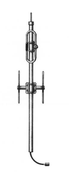
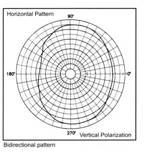
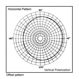
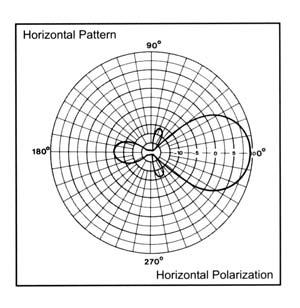
9 BASE STATION GROUND PLANE ANTENNA CP Ground Plane Antenna Series The Ground Plane Antenna Series are available in VHF and UHF configurations. These Omnidirectional antennas are wide band Unity or Gain antennas. They are constructed from high strength corrosion resistant aluminum alloy and stainless steel. All of our antennas can be completely customized to your particular applications MHz Each antenna has a rugged design to withstand the most extreme environmental conditions. Wide band Frequency applications. The mounting hardware supplied will permit 0.75 to 2.38 O.D. pipe installation. DC ground for lightning protection. Ideal for mounting on buildings Electrical Specifications Frequency Range, MHz Nominal Gain, dbd Unity Unity Bandwidth: 1.5:1 VSWR, MHz (% Ctr. Freq.) 6% 1% 15.6% (2:1) 1% Tuning Field Adj. Field Adj. Fixed Field Adj. Polarization Vertical Vertical Vertical Vertical Vertical Beamwidth (Ver. Pol) 80º 40º 71º 38º Pattern Omni Omni Omni Omni Power Rating, Watts Nominal Impedance, Ohms Lightning Protection DC Ground DC Ground DC Ground DC Ground Standard Termination Type N Male Type N Male Type N Male Type N Male Mechanical Specifications Max Length, in (mm) 58 (1473) 108 (2743) 67 (1702) 46 (1168) Width, in (mm) 55 (1397) 46 (1168) 26.5 (673) 20 (508) Weight, lbs (kg) 6.8 (3.3) 6.5 (3.0) 6.0 (2.7) 1.5 (0.7) Rated Wind Velocity: No Ice, mph (km/h) 150 (241) 125 (201) 125 (201) 125 (201) Rated Wind Velocity: 0.5 (13mm) Ice, mph (km/h) 140 (225) 85 (137) 110 (177) 85 (137) Lateral 100mph wind, lbs (kg) 31.8 (14.4) 40 (18.1) 24 (10.7) 7.3 (3.3) Bending top clamp: 100mph, ft*lb (kg*m) 41 (5.7) 94 (13) 28 (3.9) 1.6 (1.6) Projected Area, ft 2 (m 2 ) 1.2 (0.110) 1.57 (0.146) 0.88 (0.082) 0.27 (0.03) Mounting Hardware Clamp Clamp Clamp Clamp Order Information Black Adnodize n/a n/a n/a n/a * * * n/a n/a n/a n/a * * * B n/a n/a n/a n/a n/a n/a * * *3 n/a n/a n/a 8

10 GROUND PLANE ANTENNA MHz BASE STATION
11 BASE STATION OMNIDIRECTIONAL ANTENNA CP Omni directional Antenna Series The Omni directional Antenna Series are available in VHF, UHF, & 700/800/900 MHz configurations. These Omnidirectional antennas are wide band Unity Gain. They are constructed from high strength corrosion resistant aluminum alloy and stainless steel. All of our antennas can be completely customized to your particular applications. Each antenna has a rugged design to withstand the most extreme environmental conditions. The mounting hardware supplied will permit 0.75 to 2.38 O.D. pipe installation. DC ground for lightning protection. Because of the very large bandwidth, these are ideal antennas to stock, whether for re-use or resale MHz Electrical Specifications Frequency Range, MHz MHz Nominal Gain, dbd Unity Unity Unity Bandwidth: 1.5:1 VSWR, MHz 2% 20 10% Polarization Vertical Vertical Vertical Vertical Beamwidth (Ver. Pol) 78º 75º 75º Pattern Omni Omni Omni Power Rating, Watts Nominal Impedance, Ohms Lightning Protection Star Gap DC Ground DC Ground Standard Termination Type N Male Type N Male Type N Male Mechanical Specifications Max Length, in (mm) 229 (5817) 24 (610) 21 (533) Skirt Diameter, in (mm) (67) n/a n/a Whip Diameter, in (mm) 0.75 (19) n/a n/a Weight, lbs (kg) 17 (7.7) 1.4 (0.7) 1 (0.45) Rated Wind Velocity: No Ice, mph (km/h) 115 (185) 150 (241) 150 (241) Rated Wind Velocity: 0.5 (13mm) Ice, mph (km/h) n/a 100 (161) 100 (161) Lateral 100mph wind, lbs (kg) 67 (30.4) 3.9 (1.8) 3.4 (1.6) Bending top clamp: 100mph, ft*lb (kg*m) 308 (42.6) 1.84 (0.25) 1.87 (0.26) Projected Area, ft 2 (m 2 ) 2.5 (0.23) 0.15 (0.014) 0.13 (0.019) Mounting Hardware 1.7 (42mm) O.D Clamp Clamp Order Information MHz MHz MHz MHz MHz MHz n/a n/a n/a n/a n/a n/a * * *3 n/a n/a n/a n/a n/a n/a * * *3 10

12 OMNIDIRECTIONAL ANTENNA MHz BASE STATION

13 BASE STATION EXPOSED DIPOLE ANTENNA CP Low Band Exposed Dipole Antenna Series The Low Band Exposed Dipole Antenna Series are available in our standard or Heavy Duty construction. These Exposed Dipole antennas come in both single and dual configurations, depending on the gain required. They are constructed from high strength corrosion resistant aluminum alloy, hot galvanized steel mounting hardware, and use unique PVC off-set support arms. Our Heavy Duty versions have dual support braces and use a superior anti-torque support, all material is oversized. Each antenna has a rugged design to withstand the most extreme environmental conditions. Supplied with Anti-Torque supports The mounting hardware supplied will permit 1 1/4 2 3/8 tower leg installation, other clamping configurations are offered. DC ground for lightning protection. Can be Black Anodized for enhanced Anti-Corrosion and De-Icing properties 30-76MHz HD Electrical Specifications HD HD Frequency Range, MHz Nominal Gain, dbd Bandwidth: 1.5:1 VSWR, MHz 7% 7% 7% 7% Polarization Vertical Vertical Vertical Vertical Pattern UniDirect. UniDirect. UniDirect. UniDirect. Power Rating, Watts Nominal Impedance, Ohms Lightning Protection DC Ground DC Ground DC Ground DC Ground Standard Termination Type N Male Type N Male Type N Male Type N Male Mechanical Specifications 30MHz, in (mm) 189 (4800) 189 (4800) 472 (11989) 472 (11989) Width, in (mm) 87 (2210) 87 (2210) 87 (2210) 87 (2210) Weight, lbs (kg) 37 (17) 43 (19.5) 79 (36) 91 (41) Rated Wind Velocity: No Ice, mph (km/h) 143 (230) 200 (322) 143 (230) 200 (322) Rated Wind Velocity: 0.5 (13mm) Ice, mph (km/h) 98 (158) 160 (258) 98 (158) 160 (258) Lateral 100mph wind, lbs (kg) 133 (60.8) 160 (72.3) 266 (121.6) 320 (144.6) Projected Area, ft 2 (m 2 ) 4.98 (0.46) 5.94 (0.55) 9.96 (0.92) (1.10) Mounting Hardware (not included) (4) (6) (8) (12) " Order Information MHz MHz MHz MHz MHz MHz MHz MHz * * * * * * * * * * * * * * * * HD HD* HD* HD* HD* HD* HD* HD* HD* HD HD* HD* HD* HD* HD* HD* HD* HD*8 To order the Black Anodized version add suffix B to the model number, available on the Heavy Duty version only. Example: HDB*1 12


14 EXPOSED DIPOLE ANTENNA 30-76MHz BASE STATION HD 13
15 BASE STATION FM EXPOSED DIPOLES CP870 FM Series Exposed Dipoles The 870 FM Series Exposed Dipoles are available in 1, 2, 4 dipole configurations. All of our antennas can be completely customized to your particular applications. Our antennas can be Black Anodized, Adjustable or Fixed, Side Mount or Top Mount, and many version of Heavy Duty Ruggedness MHz Each antenna is offered in a 1/4 or 3/8 wave spacing versions The 87XA-70 has an external cabling and has a field adjustable pattern The 87XF-70 has an internal cabling and fixed dipole-mast spacing Heavy Duty Versions are available, but please contact a Comprod Technical support technician for consultation 872F-70FM Electrical Specifications 871F-70FM 872F-70FM 874F-70FM Frequency Range, MHz Nominal Gain, dbd Number of Dipoles Bandwidth: 1.5:1 VSWR, MHz Polarization Vertical Vertical Vertical Pattern Offset Offset Offset Power Rating, Watts Nominal Impedance, Ohms Lightning Protection DC Ground DC Ground DC Ground Standard Termination Type N Male Type N Male Type N Male Mechanical Specifications Length, in (mm) 114 (2896) 198 (5029) 350 (8890) Width (3/8 Wave Spacing), in (mm) 47 (1194) 47 (1194) 49 (1245) Weight, lbs (kg) 19.1 (8.7) 37 (16.8) 137 (62) Rated Wind Velocity: No Ice, mph (km/h) 150 (241) 128 (206) 105 (169) Rated Wind Velocity: 0.5 (13mm) Ice, mph (km/h) 118 (190) 100 (161) 84 (135) Lateral 100mph wind lbs (kg) 75 (34) 139 (63) 332 (151) Bending top clamp: 100mph, lb*ft (kg*m) 60 (8.2) 596 (82) 3565 (493) Projected area ft 2 (m 2 ) 2.8 (0.26) 5.3 (0.49) 12.5 (1.17) Mounting Information Mast 2.4 (61mm) O.D. Mast 2.4 (61mm) O.D. Mast 3.5 (89mm) O.D. Order Information Adjustable Heavy Duty Side Mount Top Mount Black Anodized FM 871A-70FM 871F-70FMHD 871F-70FMSM 871F-70FMTM 871F-70FMHDB FM 872A-70FM 872F-70FMHD 872F-70FMSM 872F-70FMTM 872F-70FMHDB FM 874A-70FM 874F-70FMHD 874F-70FMSM 874F-70FMTM 874F-70FMHDB 14
16 FM EXPOSED DIPOLES MHz BASE STATION 871F-70FM 872F-70FM 874F-70FM 15
17 BASE STATION VHF EXPOSED DIPOLES CP870 Series VHF Exposed Dipoles The 870 Series AV Aviation Series VHF Exposed Dipoles are available in 1, 2, 4, 8, and dual dipole configurations. All of our antennas can be completely customized to your particular applications. Our antennas can be Black Anodized, Adjustable or Fixed, Side Mount or Top Mount, and many version of Heavy Duty Ruggedness. Each antenna is offered in a 1/4, 3/8, or 1/2 wave versions The 87XA-70 has an external cabling and has a field adjustable pattern. The 87XF-70 has an internal cabling and fixed dipole-mast spacing. Heavy Duty Versions are available, but please contact a Comprod Technical support technician for consultation MHz 872F-70AV Electrical Specifications 871F-70AV 872F-70AV 874F-70AV Frequency Range, MHz Nominal Gain, dbd Number of Dipoles Bandwidth: 1.5:1 VSWR, MHz Polarization Vertical Vertical Vertical Pattern Offset Offset Offset Power Rating, Watts Nominal Impedance, Ohms Lightning Protection DC Ground DC Ground DC Ground Standard Termination Type N Male Type N Male Type N Male Mechanical Specifications Length, in (mm) 78 (1981) 162 (4115) 294 (7468) Width (1/2 Wave Spacing), in (mm) 54 (1372) 54 (1372) 55 (1397) Weight, lbs (kg) 16 (7.3) 31 (14.1) 93 (42) Rated Wind Velocity: No Ice, mph (km/h) 150 (241) 145 (3341) 120 (193) Rated Wind Velocity: 0.5 (13mm) Ice, mph (km/h) 105 (169) 100 (161) 95 (153) Lateral 100mph wind lbs (kg) 57 (26) 120 (54.5) 231 (105) Bending top clamp: 100mph, lb*ft (kg*m) 82 (11) 420 (58) 1437 (199) Projected Area ft 2 (m 2 ) 2.2 (0.2) 4.6 (0.43) 8.8 (0.82) Mounting Information Mast 2.4 (61mm) O.D. Mast 2.4 (61mm) O.D. Mast 2.9 (73mm) O.D. Order Information Adjustable Heavy Duty Side Mount Top Mount Black Anodized AV 871A-70AV 871F-70AV-HD 871F-70AV-SM 871F-70AV-TM 871F-70AV-HDB AV 872A-70AV 872F-70AV-HD 872F-70AV-SM 872F-70AV-TM 872F-70AV-HDB AV 874A-70AV 874F-70AV-HD 874F-70AV-SM 874F-70AV-TM 874F-70AV-HDB 16
18 VHF EXPOSED DIPOLES MHz BASE STATION 871F-70AV 872F-70AV 874F-70AV 17
19 BASE STATION VHF EXPOSED DIPOLES CP870 Series VHF Exposed Dipoles The 870 Series VHF Exposed Dipoles are available in 1, 2, 4, 8, dipole and dual dipole configurations. All of our antennas can be completely customized to your particular applications. Our antennas can be Black Anodized, Adjustable or Fixed, Side Mount or Top Mount, and many version of Heavy Duty Ruggedness MHz Each antenna is offered in a 1/4, 3/8, or 1/2 wave versions. The 87XA-70 has an external cabling and has a field adjustable pattern. The 87XF-70 has an internal cabling and fixed dipole-mast spacing. Heavy Duty Versions are available, but please contact a Comprod Technical support technician for consultation. 872F-70 Electrical Specifications 871F F F-70 Frequency Range, MHz Nominal Gain, dbd Number of Dipoles Bandwidth: 1.5:1 VSWR, MHz Polarization Vertical Vertical Vertical Pattern Offset Offset Offset Power Rating, Watts Nominal Impedance, Ohms Lightning Protection DC Ground DC Ground DC Ground Standard Termination Type N Male Type N Male Type N Male Mechanical Specifications Length, in (mm) 78 (1981) 126 (3200) 246 (6248) Width (1/2 Wave Spacing), in (mm) 40 (1016) 40 (1016) 40 (1016) Weight, lbs (kg) 11.8 (5.4) 24 (10.8) 67 (30) Rated Wind Velocity: No Ice, mph (km/h) 170 (241) 150 (241) 145 (233) Rated Wind Velocity: 0.5 (13mm) Ice, mph (km/h) 145 (217) 135 (217) 95 (153) Lateral 100mph wind lbs (kg) 45 (20.5) 92 (41.7) 160 (72.6) Bending top clamp: 100mph, lb*ft (kg*m) 18 (2.5) 205 (28.4) 1364 (188.7) Projected Area ft 2 (m 2 ) 1.7 (0.16) 3.5 (0.33) 7 (0.65) Mounting Information Mast 1.9 (48mm) O.D. Mast 2.4 (61mm) O.D. Mast 2.9 (61mm) O.D. Order Information Adjustable Heavy Duty Side Mount Top Mount Black Anodized A F-70HD 871F-70SM 871F-70TM 871F-70HDB A F-70HD 872F-70SM 872F-70TM 872F-70HDB A F-70HD 874F-70SM 874F-70TM 874F-70HDB 18


20 VHF EXPOSED DIPOLES MHz BASE STATION 871F F F-70 19
21 BASE STATION 220MHz EXPOSED DIPOLES CP870 Series 220MHz Exposed Dipoles The 870 Series 220MHz Exposed Dipoles are available in 1, 2, 4, 8, dipole configurations. All of our antennas can be completely customized to your particular applications. Our antennas can be Black Anodized, Adjustable or Fixed, Side Mount or Top Mount, and many version of Heavy Duty Ruggedness MHz Each antenna is offered in a 1/4, 3/8, or 1/2 wave versions. The 87XA has external cabling and has a field adjustable pattern. The 87XF has an internal cabling and fixed dipole-mast spacing. Heavy Duty Versions are available, but please contact a Comprod Technical support technician for consultation. 872F Electrical Specifications 871F F F Frequency Range, MHz Nominal Gain, dbd Number of Dipoles Bandwidth: 1.5:1 VSWR, MHz Polarization Vertical Vertical Vertical Pattern Offset Offset Offset Power Rating, Watts Nominal Impedance, Ohms Lightning Protection DC Ground DC Ground DC Ground Standard Termination Type N Male Type N Male Type N Male Mechanical Specifications Length, in (mm) 66 (1676) 112 (2845) 200 (5080) Width (1/2 Wave Spacing), in (mm) 31 (787) 31 (787) 32 (813) Weight, lbs (kg) 12.5 (5.7) 21 (9.5) 51 (23) Rated Wind Velocity: No Ice, mph (km/h) 165 (266) 150 (241) 145 (233) Rated Wind Velocity: 0.5 (13mm) Ice, mph (km/h) 140 (225) 130 (209) 105 (177) Lateral 100mph wind lbs (kg) 40 (18) 66 (30) 143 (65) Bending top clamp: 100mph, lb*ft (kg*m) 58 (8) 150 (21) 610 (84) Projected Area ft 2 (m 2 ) 1.5 (0.14) 2.6 (0.24) 5.5 (0.51) Mounting Information Mast 1.9 (48mm) O.D. Mast 1.9 (48mm) O.D. Mast 2.4 (60mm) O.D. Order Information Heavy Duty Side Mount Top Mount Black Anodized F HD 871F SM 871F TM 871F HDB F HD 872F SM 872F TM 872F HDB F HD 874F SM 874F TM 874F HDB 20

22 220MHz EXPOSED DIPOLES MHz BASE STATION 871F F F
23 BASE STATION VHF EXPOSED DIPOLES CP870 LM Series VHF Exposed Dipoles The 870 LM Series VHF Exposed Dipoles are available in 1, 2, 4, 8, dipole configurations. The LM stands for Less Mast. The product includes the dipole, the boom, the clamps to mount the dipoles, but no mast is supplied. All of our antennas can be completely customized to your particular applications. Our antennas can be Black Anodized, Adjustable only, Side Mount or Top Mount, and many version of Heavy Duty Ruggedness. External cabling and is field adjustable pattern Heavy Duty Versions are available, but please contact a Comprod Technical support technician for consultation MHz LM Electrical Specifications LM LM LM Frequency Range, MHz Nominal Gain, dbd Number of Dipoles Bandwidth: 1.5:1 VSWR, MHz Polarization Vertical Vertical Vertical Pattern Offset Offset Offset Power Rating, Watts Nominal Impedance, Ohms Lightning Protection DC Ground DC Ground DC Ground Standard Termination Type N Male Type N Male Type N Male Mechanical Specifications Length, in (mm) Mast Not Incl. Mast Not Incl. Mast Not Incl. Width (1/2 Wave Spacing), in (mm) 40 (1016) 40 (1016) 40 (1016) Weight, lbs (kg) 4.5 (2.0) 19 (8.6) 38 (17.2) Rated Wind Velocity: No Ice, mph (km/h) 150 (241) 150 (241) 150 (241) Rated Wind Velocity: 0.5 (13mm) Ice, mph (km/h) 135 (217) 135 (217) 135 (217) Lateral 100mph wind lbs (kg) 20 (9.1) 40 (18.2) 80 (36.5) Projected Area ft 2 (m 2 ) 0.92 (0.08) 1.84 (0.17) 3.64 (0.34) Mounting Hardware Supplied R R-85 Order Information Heavy Duty Black Anodized w/mast LM LMHD LMHDB 871A LM LMHD LMHDB 872A LM LMHD LMHDB 874A-70 22


24 VHF EXPOSED DIPOLES MHz BASE STATION LM LM LM 23
25 BASE STATION VHF EXPOSED DIPOLES CP 840 Series Light Duty VHF Exposed Dipoles The 840 Series Light Duty VHF Exposed Dipoles are available in 2 and 4 dipole configurations. All of our antennas can be completely customized to your particular applications. Low VSWR version, with maximum gain over specified frequency The 840 series has an internal cabling and fixed dipole-mast spacing. These antennas have an adjustable pattern for Omnidirectional or offset coverage MHz Electrical Specifications Frequency Range, MHz Nominal Gain, dbd 3.0/ /9.0 Number of Dipoles 2 4 Bandwidth: 2:1 VSWR, MHz Polarization Vertical Vertical Pattern Omni or Bi-Dir. Omni or Bi-Dir. Power Rating, Watts Nominal Impedance, Ohms Lightning Protection DC Ground DC Ground Standard Termination Type N Male Type N Male Mechanical Specifications Length, in (mm) 138 (3500) 270 (6858) Width, in (mm) 9 (229) 9 (229) Weight, lbs (kg) 22 (10) 40 (18) Rated Wind Velocity: No Ice, mph (km/h) 150 (241) 110 (177) Rated Wind Velocity: 0.5 (13mm) Ice, mph (km/h) 115 (185) 80 (129) Lateral 100mph wind lbs (kg) 70 (31.8) 139 (63) Bending top clamp: 100mph, lb*ft (kg*m) 167 (23.1) 514 (71) Projected Area ft 2 (m 2 ) 2.6 (0.24) 5.2 (0.48) Mounting Information clamp set clamp set Order Information MHz MHz * * * *2 24

26 VHF EXPOSED DIPOLES MHz BASE STATION

27 BASE STATION VHF EXPOSED DIPOLES W/REFLECTORS CP870 Series VHF Exposed Dipoles w/reflectors The 870 Series VHF Exposed Dipoles w/reflectors are available in 1, 2, 4, dipole configurations. All of our antennas can be completely customized to your particular applications. Our antennas can be Black Anodized, Fully Welded, Side Mount or Top Mount, and many version of Heavy Duty Ruggedness. The Reflectors not only provide a higher degree of directivity, but can also prevent RF backsplash. This product is great for State borders or Country borders. We have seen great success with being able to shape the RF patterns in the 870 Series antenna line MHz Each antenna is offered in a 3/8 wave version. The reflectors provide more directivity and greater front-to-back ratios. These Exposed Dipoles all have internal cabling and fixed dipolemast spacing. Heavy Duty Versions are available, but please contact a Comprod Technical support technician for consultation. F-3713 Electrical Specifications F-3729 F-3713 F-3766 Frequency Range, MHz Nominal Gain, dbd Number of Dipoles Number of Reflectors Bandwidth: 1.5:1 VSWR, MHz Polarization Vertical Vertical Vertical Pattern Directional Directional Directional Power Rating, Watts Nominal Impedance, Ohms Lightning Protection DC Ground DC Ground DC Ground Standard Termination Type N Male Type N Male Type N Male Mechanical Specifications Length, in (mm) 72 (1829) 120 (3048) 240 (6096) Width (1/2 Wave Spacing), in (mm) 50 (1270) 53 (1346) 53 (1346) Weight, lbs (kg) 34.3 (15.6) 57.2 (26) (45.5) Mounting Information Mast 2.4 (61mm) O.D. Mast 2.4 (61mm) O.D. Mast 2.9 (73mm) O.D. Order Information Heavy Duty Side Mount Top Mount Black Anodized F-3729 F-3729HD F-3729SM F-3729TM F-3729B F-3713 F-3713HD F-3713SM F-3713TM F-3713B F-3766 F-3766HD F-3766SM F-3766TM F-3766B Please call for other available models. 26


28 VHF EXPOSED DIPOLES W/REFLECTORS MHz BASE STATION F-3729 F-3766 F
29 BASE STATION DUAL EXPOSED DIPOLE ARRAY CP Dual Exposed Dipole Array The Dual Exposed Dipole Arrays are available in many different configurations. VHF, UHF, and/or 700/800/900MHz antennas can be combined onto one mast. These antennas can be mixed and matched with our 840, 870, 880, 770, 790 series antennas. All of our antennas can be completely customized to your particular applications. Our antennas can be Side Mount or Top Mount. Low VSWR version, with maximum gain over specified frequency Great for applications were costs are calculated per antenna. Heavy Duty versions are available. Some versions of antennas have an adjustable pattern for 3dBd Omnidirectional or 6dBd offset coverage *40 Electrical Specifications Frequency Range, MHz Nominal Gain, dbd / Number of Dipoles 2 sets of 2 2 sets of 2 2 sets of 2 Bandwidth: VSWR (MHz) 1.5:1 (106) 2:1 (14) 1.5:1 (36) Polarization Vertical Vertical Vertical Pattern Offset Omni or Offset Offset Power Rating, Watts Nominal Impedance, Ohms Lightning Protection DC Ground DC Ground DC Ground Standard Termination Type N Male Type N Male Type N Male Mechanical Specifications Length, in (mm) 126 (3200) 270 (6858) 246 (6248) Width (1/2 Wave Spacing), in (mm) 16 (406) 9 (229) 40 (1016) Weight, lbs (kg) 19 (8.6) 42 (19) 67 (30) Rated Wind Velocity: No Ice, mph (km/h) 150 (241) 110 (177) 145 (233) Rated Wind Velocity: 0.5 (13mm) Ice, mph (km/h) 150 (241) 80 (129) 95 (153) Lateral 100mph wind lbs (kg) 44 (20) 139 (63) 160 (72.6) Bending top clamp: 100mph, lb*ft (kg*m) 193 (26.7) 514 (71) 1364 (188.7) Projected Area ft 2 (m 2 ) 1.38 (0.128) 5.2 (0.48) 7 (0.65) Mounting Information Mast 1.9 (48) O.D clamp Mast 2.9 (61) O.D TM Order Information Frequency 2* * * Side Mount Top Mount Black Anodized MHz n/a n/a n/a n/a HDB MHz n/a *1 n/a n/a n/a n/a MHz n/a *2 n/a n/a n/a n/a MHz n/a n/a 876F F-70SM 876F-70TM 876F-70HDB Please call for other available models. 28

30 DUAL EXPOSED DIPOLE ARRAY BASE STATION F-70 29
31 BASE STATION AVIATION EXPOSED DIPOLE ARRAY CP880AV Series VHF Exposed Dipole Array The 880AV Series VHF Exposed Dipole Array are available in 2 and 4 dipole set configurations. All of our antennas can be completely customized to your particular applications. Our antennas can be Black Anodized, Top Mount only, and many version of Heavy Duty Ruggedness are all available. Each antenna is offered in two versions, Omni or Bi-Directional. These antennas have only internal cabling, fixed dipole-mast spacing, and adjustable pattern control. Heavy Duty versions are available, but please contact a Comprod Technical support technician for consultation MHz AV Electrical Specifications AV AV Frequency Range, MHz Nominal Gain, dbd 3.0/ /8.5 Number of Dipoles 2 Sets 4 Sets Bandwidth: 1.5:1 VSWR, MHz Polarization Vertical Vertical Pattern Omni or Bi-Dir. Omni or Bi-Dir. Power Rating, Watts Nominal Impedance, Ohms Lightning Protection DC Ground DC Ground Standard Termination Type N Male Type N Male Mechanical Specifications Length, in (mm) 157 (3988) 306 (7772) Width, in (mm) 45 (1143) 46 (1168) Weight, lbs (kg) 49 (8.6) 105 (47.6) Rated Wind Velocity: No Ice, mph (km/h) 140 (225) 100 (162) Rated Wind Velocity: 0.5 (13mm) Ice, mph (km/h)" 110 (177) 80 (129) Lateral 100mph wind lbs (kg) 154 (70) 307 (139) Bending top clamp: 100mph, lb*ft (kg*m)" 524 (72.5) 2039 (282) Projected Area ft 2 (m 2 ) 5.6 (0.52) 11 (1.04) Mounting Information Mast 2.9 (73) O.D. Mast 3.5 (89) O.D. Order Information Heavy Duty Black Anodized AV AVHD AVHDB AV AVHD AVHDB 30
32 AVIATION EXPOSED DIPOLE ARRAY MHz BASE STATION AV AV 31
33 BASE STATION VHF EXPOSED DIPOLE ARRAY CP880 Series VHF Exposed Dipole Array The 880 Series VHF Exposed Dipole Array are available in 2 and 4 dipole set configurations. All of our antennas can be completely customized to your particular applications. Our antennas can be Black Anodized, Top Mount only, and many version of Heavy Duty Ruggedness are all available. Each antenna is offered in two versions, Omni or Bi-Directional. These antennas have only internal cabling, fixed dipole-mast spacing, and adjustable pattern control. Heavy Duty versions are available, but please contact a Comprod Technical support technician for consultation MHz Electrical Specifications Frequency Range, MHz Nominal Gain, dbd 3.0/ /8.5 Number of Dipoles 2 Sets 4 Sets Bandwidth: 1.5:1 VSWR, MHz Polarization Vertical Vertical Pattern Omni or Bi-Dir. Omni or Bi-Dir. Power Rating, Watts Nominal Impedance, Ohms Lightning Protection DC Ground DC Ground Standard Termination Type N Male Type N Male Mechanical Specifications Length, in (mm) 138 (3500) 246 (6248) Width, in (mm) 30 (762) 31 (787) Weight, lbs (kg) 36 (16.3) 78 (35) Rated Wind Velocity: No Ice, mph (km/h) 120 (162) 110 (177) Rated Wind Velocity: 0.5 (13mm) Ice, mph (km/h) 95 (137) 80 (129) Lateral 100mph wind lb (kg) 113 (51) 236(107) Bending top clamp: 100mph, lb*ft (kg*m) 351 (49) 1264 (175) Projected Area ft 2 (m 2 ) 4.1 (0.38) 8.7 (0.81) Mounting Information Mast 2.4 (61 mm) O.D. Mast 2.9 (73 mm) O.D. Order Information Heavy Duty Black Anodized HD HDB HD HDB 32


34 VHF EXPOSED DIPOLE ARRAY MHz BASE STATION
35 BASE STATION UHF EXPOSED DIPOLES CP770 Series UHF Exposed Dipoles The 770 Series UHF Exposed Dipoles are available in 1, 2, 4, 8, and dual dipole configurations. All of our antennas can be completely customized to your particular applications. Our antennas can be Black Anodized, Adjustable or Fixed, Side Mount or Top Mount, and many versions of Heavy Duty Ruggedness MHz Each antenna is offered in a 1/4, 3/8, or 1/2 wave versions. The 77X-70 has an internal cabling and fixed dipole-mast spacing. Heavy Duty Versions are available, but please contact a Comprod Technical support technician for consultation Electrical Specifications Frequency Range, MHz Nominal Gain, dbd Number of Dipoles Bandwidth: 1.5:1 VSWR, MHz Polarization Vertical Vertical Vertical Vertical Pattern Offset Offset Offset Offset Power Rating, Watts Nominal Impedance, Ohms Lightning Protection DC Ground DC Ground DC Ground DC Ground Standard Termination Type N Male Type N Male Type N Male Type N Male Mechanical Specifications Length, in (mm) 66 (1676) 86 (2184) 126 (3200) 210 (5334) Width (1/2 Wave Spacing), in (mm) 16 (406) 16 (406) 16 (406) 17 (432) Weight, lbs (kg) 8.6 (3.9) 12.6 (5.7) 21 (9.5) 52 (23.6) Rated Wind Velocity: No Ice, mph (km/h) 170 (274) 160 (257) 150 (241) 140 (225) Rated Wind Velocity: 0.5 (13mm) Ice, mph (km/h) 145 (233) 135 (217) 120 (193) 105 (169) Lateral 100mph wind, lbs (kg) 27 (12.3) 39 (17.8) 64 (29) 134 (61) Bending Moment top clamp: 100mph, lb*ft (kg*m) 33.5 (4.6) 72 (10) 177 (24.5) 655 (91) Projected Area ft 2 (m 2 ) 1 (0.09) 1.5 (0.14) 2.4 (0.23) 5.1 (0.472) Mounting Information: Mast O.D. 1.9 (48mm) 1.9 (48mm) 1.9 (48mm) 2.4 (61mm) Order Information Side Mount Top Mount Heavy Duty Welded Black Anodized SM TM HD HDW HDB SM TM HD HDW HDB SM TM HD HDW HDB SM TM HD HDW HDB 34

36 UHF EXPOSED DIPOLES MHz BASE STATION
37 BASE STATION UHF EXPOSED DIPOLE ARRAY CP780 Series UHF Exposed Dipole Array The 780 Series UHF Exposed Dipole Arrays are available in 2 and 4 dipole set configurations. All of our antennas can be completely customized to your particular applications. Our antennas can be Black Anodized, Top Mount only, and many versions of Heavy Duty Ruggedness are all available. Each antenna is offered in two versions, Omni or Bi-Directional. These antennas have only internal cabling, fixed dipole-mast spacing, and adjustable pattern control. Heavy Duty versions are available, but please contact a Comprod Technical support technician for consultation MHz Electrical Specifications Frequency Range, MHz Nominal Gain, dbd 3.0/ /8.5 Number of Dipoles 2 Sets 4 Sets Bandwidth: 1.5:1 VSWR, MHz Polarization Vertical Vertical Pattern Omni or Bi-Dir. Omni or Bi-Dir. Power Rating, Watts Nominal Impedance, Ohms Lightning Protection DC Ground DC Ground Standard Termination Type N Male Type N Male Mechanical Specifications Length, in (mm) 90 (2286) 126 (3200) Width (1/2 Wave Spacing), in (mm) (324) (324) Weight, lbs (kg) 25 (11.3) 38 (17) Rated Wind Velocity: No Ice, mph (km/h) 145 (233) 130 (209) Rated Wind Velocity: 0.5 (13mm) Ice, mph (km/h) 100 (161) 90 (145) Lateral 100mph wind lbs (kg) 54 (24.5) 101 (46) Bending top clamp: 100mph, lb*ft (kg*m) 137 (19) 426 (59) Projected Area ft 2 (m 2 ) 2.0 (0.19) 3.5 (0.33) Mounting Information Mast 1.9 (48mm) O.D. Mast 2.4 (60mm) O.D. Order Information Heavy Duty Black Anodized MHz MHz HD HDB * * HD HDB * *2 36


38 UHF EXPOSED DIPOLE ARRAY MHz BASE STATION
39 BASE STATION DUAL ANTENNA ARRAY CP Dual Antenna Array The Dual Antenna Arrays are available in many different configurations. VHF, UHF, and/or 700/800/900MHz antennas can be combined onto one mast. These antennas can be mixed and matched from our 870, 770, 790 series antennas. All of our antennas can be completely customized to your particular applications. Our antennas can be Side Mount or Top Mount. Low VSWR version, with maximum gain over specified frequency Great for applications were costs are calculated per antenna. Heavy Duty versions are available Multiple combinations are available and customizable, please contact a Comprod Technical support technician for more details. Electrical Specifications F-3676 F-3661 F-3647 Frequency Range, MHz Nominal Gain, dbd Number of Dipoles Bandwidth: 1.5:1 VSWR, MHz Polarization Vertical Vertical Vertical Pattern Offset Offset Offset Power Rating, Watts Nominal Impedance, Ohms Lightning Protection DC Ground DC Ground DC Ground Standard Termination Dual Feed Type N Male Type N Male Type N Male Mechanical Specifications F-3661 Length, in (mm) 354 (8992) 186 (4724) 126 (3200) Width (1/2 Wave Spacing), in (mm) 41 (1041) 40 (1016) 40 (1016) Weight, lbs (kg) 117 (53) 59 (26.8) 26 (11.9) Rated Wind Velocity: No Ice, mph (km/h) 110 (177) 150 (241) 170 (272) Rated Wind Velocity: 0.5 (13mm) Ice, mph (km/h) 85 (137) 110 (177) 140 (225) Lateral 100mph wind lbs (kg) 315 (143) 154 (70) 67 (30.5) Bending top clamp: 100mph, lb*ft (kg*m) 2469 (341) 720 (100) 110 (15) Projected Area ft 2 (m 2 ) 12 (1.12) 5.7 (0.53) 2.5 (0.23) Mounting Information Mast 3.5 (89mm) O.D. Mast 2.9 (73mm) O.D. Mast 1.9" (48 mm) O.D. Order Information Side Mount Top Mount Heavy Duty Black Anodized F-3676 F-3676SM F-3676TM F-3676HD F-3676HDB F-3661 F-3661SM F-3661TM F-3661HD F-3661HDB F-3647 F-3647SM F-3647TM F-3647HD F-3647HDB Please call for other available models. 38
40 DUAL ANTENNA ARRAY BASE STATION F-3676 F

41 BASE STATION 790 SERIES ENCLOSED DIPOLE MHz CP790 Series Enclosed Dipoles The 790 Series Enclosed Dipoles are available in 2, 4, or 9 dipole configurations. All of our antennas can be completely customized to your particular applications. Each antenna is offered in an offset or bi-directional pattern. Broadband, ideal for trunking or cellular applications. Weatherproof radome to ensure continuous service in severe environments Electrical Specifications Frequency Range, MHz Nominal Gain, dbd Number of Dipoles Bandwidth: 1.5:1 VSWR, MHz Polarization Vertical Vertical Vertical Pattern Offset or Bi-Dir. Offset or Bi-Dir. Offset or Bi-Dir. Power Rating, Watts Nominal Impedance, Ohms Lightning Protection DC Ground DC Ground DC Ground Standard Termination Type N Male Type N Male Type N Male Mechanical Specifications Length, in (mm) 22 (559) 44.5 (1130) 94 (2388) Width, in (mm) 2.5 (64) 2.5 (64) 2.5 (64) Weight, lbs (kg) 8.8 (4) 14 (6.5) 24 (11) Rated Wind Velocity: No Ice, mph (km/h) 100 (162) 100 (162) 100 (162) Rated Wind Velocity: 0.5 (13mm) Ice, mph (km/h) 85 (137) 85 (137) 85 (137) Lateral 100mph wind lbs (kg) 36.4 (16.5) 73 (33) 153 (59) Projected Area ft 2 (m 2 ) 1.4 (0.13) 2.7 (0.25) 5.7 (0.53) Mounting Information (Clamps incl.) O.D O.D O.D. Order Information MHz MHz MHz W/Reflector * * * R * * * R * * * R 40


42 790 SERIES ENCLOSED DIPOLE MHz BASE STATION

43 BASE STATION 790 SERIES ENCLOSED DIPOLE W/REFLECTOR MHz CP790 Series Enclosed Dipoles w/reflector The 790 Series Enclosed Dipoles w/reflector are available in 2, 4, or 9 dipole configurations. These antennas can be sectorized from 60º to 160º. All of our antennas can be completely customized to your particular applications. Broadband, ideal for trunking or cellular applications. The Reflector is field adjustable and has 5 positions, 60º, 90º, 105º, 130º, and 160º. Weatherproof radome to ensure continuous service in severe environments. Heavy Duty versions are available, but please contact a Comprod Technical support technician for consultation R Electrical Specifications R R R Frequency Range, MHz Nominal Gain, dbd Up to 8.0 Up to 13.5 Up to 15.0 Number of Dipoles Bandwidth: 1.5:1 VSWR, MHz Polarization Vertical Vertical Vertical Pattern Directional Directional Directional Power Rating, Watts Nominal Impedance, Ohms Lightning Protection DC Ground DC Ground DC Ground Standard Termination Type N Male Type N Male Type N Male Mechanical Specifications Length, in (mm) 22 (559) 44.5 (1130) 94.5 (2395) Width, in (mm) 25 (635) 25 (635) 25 (635) Weight, lbs (kg) 16.5 (7.5) 24 (10.9) 42 (19) Rated Wind Velocity: No Ice, mph (km/h) 100 (162) 100 (162) 100 (162) Rated Wind Velocity: 0.5 (13mm) Ice, mph (km/h) 85 (137) 85 (137) 85 (137) Lateral 100mph wind 57 (26) 115 (52) 243 (110) Projected Area ft 2 (m 2 ) 2.0 (0.19) 4.3 (0.40) 9 (0.84) Mounting Information (Clamps incl.) O.D O.D O.D. Order Information MHz MHz MHz MHz No Reflector R R* R* R* R* R R* R* R* R* R R* R* R* R*


44 790 SERIES ENCLOSED DIPOLE W/REFLECTOR MHz BASE STATION Call for 60, 90, 105, 130, 160 patterns Call for 60, 90, 105, 130, 160 patterns R R Call for 60, 90, 105, 130, 160 patterns R 43
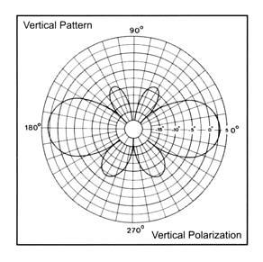
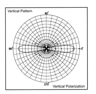
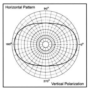
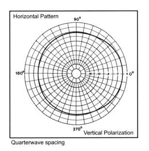
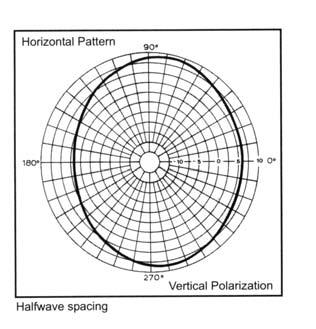
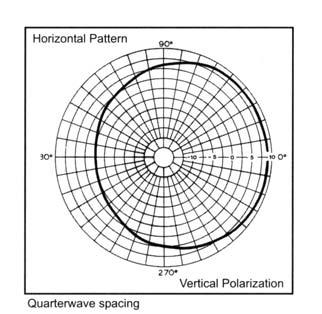
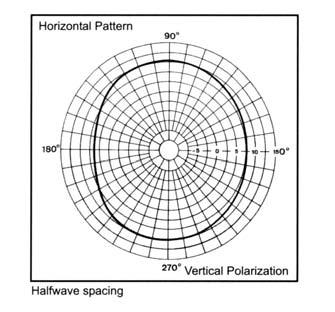
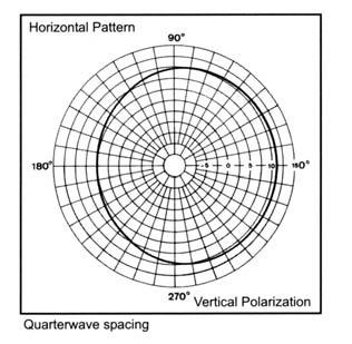
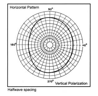
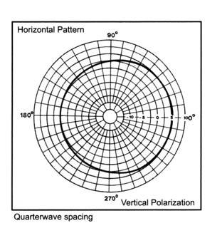
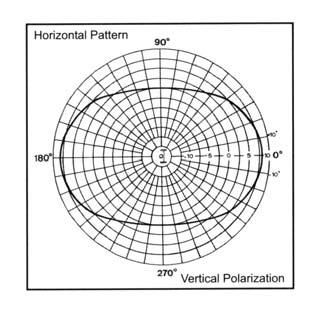
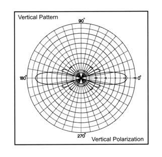
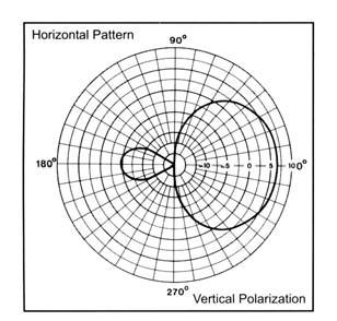
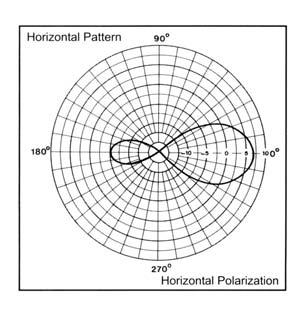
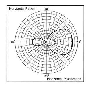
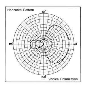
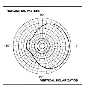
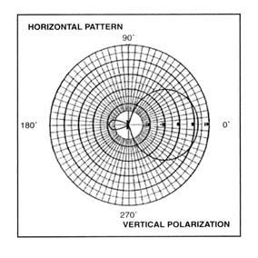
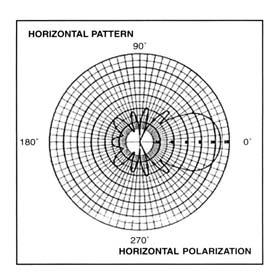
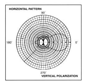
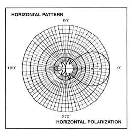
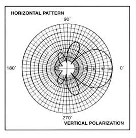
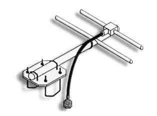
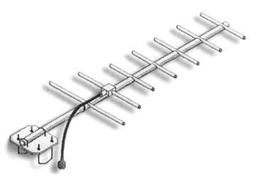
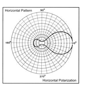
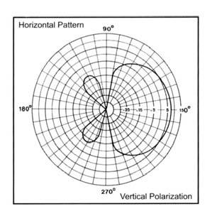
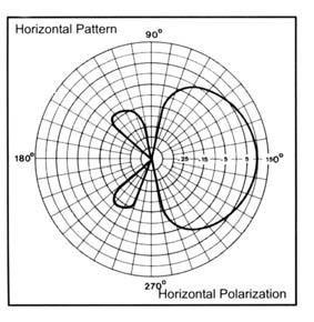
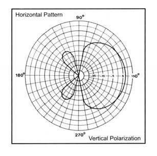
45 BASE STATION VHF YAGI ANTENNA CP290 Series VHF Yagi Antennas The 290 Series VHF Yagi Antenna are available in 2, 3, and 6 element configurations. All of our antennas can be completely customized to your particular applications. Our antennas can be Black Anodized, Welded, Vertically or Horizontally Polarized, and many versions of Heavy Duty Ruggedness are available. Each antenna has a rugged design to withstand harsh environmental conditions The mounting hardware supplied will permit either vertical or horizontal polarization DC ground for lightning protection Option to have the entire antenna welded for added durability Heavy Duty versions are available, but please contact a Comprod Technical support technician for consultation MHz Electrical Specifications Frequency Range, MHz Nominal Gain, dbd Number of Elements Bandwidth: 1.5:1 VSWR, MHz (Ctr. Freq.%) 3.75% 4% 4% 2:1 Polarization Vert. or Horz. Vert. or Horz. Vert. or Horz. Vert. or Horz. Horizontal Beamwidth (Ver. Pol) 140º 90º 62º 80º Vertical Beamwidth (Ver. Pol) 70º 61º 50º 60º Front to Back, db Pattern Direct. Direct. Direct. Direct. Power Rating, Watts Nominal Impedance, Ohms Lightning Protection DC Ground DC Ground DC Ground DC Ground Standard Termination Type N Male Type N Male Type N Male Type N Male Mechanical Specifications Length, in (mm) 50 (1270) 60 (1524) 108 (2743) 104 (2642) Width (1/2 Wave Spacing), in (mm) 40 (1016) 43 (1092) 42 (1067) 42 (1067) Weight, lbs (kg) 4.8 (2.2) 6.5 (2.9) 12.0 (5.4) 12.0 (5.4) Rated Wind Velocity: No Ice, mph (km/h) 150 (241) 145 (223) 120 (177) 110 (177) Rated Wind Velocity: 0.5 (13mm) Ice, mph (km/h) 105 (169) 100 (161) 85 (137) 90 (145) Lateral 100mph wind, lbs (kg) 29 (13) 39 (18) 65 (29) 95 (43) Projected Area ft 2 (m 2 ) 1.1 (0.10) 1.4 (0.13) 2.4 (0.22) 2.6 (0.24) Mounting Information: Mast O.D Clamp Clamp Clamp Clamp Order Information End Mount End Boom Center Mount Welded Heavy Duty Black Anodized (2) Stacked n/a n/a W HD B Call n/a CB W HD B Call EB CB W HD B n/a W HD B Call 44
46 VHF YAGI ANTENNA MHz BASE STATION
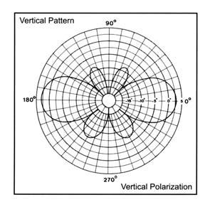
47 BASE STATION VHF YAGI ANTENNA CP290 Series 220MHz Yagi Antennas The 290 Series 220MHz Yagi Antennas are available in 2, 3, and 6 element configurations. All of our antennas can be completely customized to your particular applications. Our antennas can be Black Anodized, Welded, Vertically or Horizontally Polarized, and we have many version of Heavy Duty Ruggedness. Each antenna has a rugged design to withstand harsh environmental conditions. The mounting hardware supplied will permit either vertical or horizontal polarization DC ground for lightning protection Option to have the entire antenna welded for added durability Heavy Duty Versions are available, but please contact a Comprod Technical support technician for consultation MHz Electrical Specifications Frequency Range, MHz Nominal Gain, dbd Number of Elements Bandwidth: 1.5:1 VSWR, MHz Polarization Vert. or Horz. Vert. or Horz. Vert. or Horz. Horizontal Beamwidth (Ver. Pol) 140º 90º 62º Vertical Beamwidth (Ver. Pol) 70º 36º 50º Front to Back, db Pattern Direct. Direct. Direct. Power Rating, Watts Nominal Impedance, Ohms Lightning Protection DC Ground DC Ground DC Ground Standard Termination Type N Male Type N Male Type N Male Mechanical Specifications Length, in (mm) 32 (813) 48 (1219) 84 (2134) Width, in (mm) 29 (737) 28 (711) 27 (686) Weight, lbs (kg) 3.7 (1.7) 4.8 (2.2) 9.0 (4.1) Rated Wind Velocity: No Ice, mph (km/h) 165 (266) 155 (249) 145 (233) Rated Wind Velocity: 0.5 (13mm) Ice, mph (km/h) 145 (233) 130 (209) 100 (161) Lateral 100mph wind, lbs (kg) 19.4 (8.8) 27 (12) 47 (21.3) Torsional 100mph, ft*lb (kg*m) 25 (3.5) 52 (7.2) 138 (19) Projected Area, ft 2 (m 2 ) 0.7 (0.07) 1.0 (0.09) 1.75 (0.16) Mounting Information: Mast O.D Clamp Clamp 115R-85 Clamp Order Information End Boom Welded Heavy Duty Black Anodized (2) Stacked EB W HD HDB-220 n/a EB W HD HDB-220 n/a EB W HD HDB

48 VHF YAGI ANTENNA MHz BASE STATION
49 BASE STATION UHF YAGI ANTENNA CP UHF Yagi Antennas Series The UHF Yagi Antenna Series are available in 2, 3, 7 element and our 70 MHz wideband configuration. All of our antennas can be completely customized to your particular applications. Our antennas can be Black Anodized, Fully Welded, Vertically or Horizontally Polarized, and many version of Heavy Duty Ruggedness are available. Each antenna has a rugged fully welded design to withstand harsh environmental conditions. The mounting hardware supplied will allow either vertical or horizontal polarization. DC ground for lightning protection. All UHF yagi antennas are fully welded. Heavy Duty Versions are available, but please contact a Comprod Technical support technician for consultation MHz Electrical Specifications F Frequency Range, MHz Nominal Gain, dbd Number of Elements Bandwidth: 1.5:1 VSWR, MHz Polarization Vert. or Horz. Vert. or Horz. Vert. or Horz. Vert. or Horz. Horizontal Beamwidth (Ver. Pol) 138º 83º 62º 62º Vertical Beamwidth (Ver. Pol) 72º 59º 48º 50º Front to Back, db Pattern Direct. Direct. Direct. Direct. Power Rating, Watts Nominal Impedance, Ohms Lightning Protection DC Ground DC Ground DC Ground DC Ground Standard Termination Type N Male Type N Male Type N Male Type N Male Mechanical Specifications Length, in (mm) 28 (711) 23 (584) 45 (1143) 45 (1143) Width, in (mm) 14.5 (368) 14 (355) 14.5 (368) 14.4 (366) Weight, lbs (kg) 2.8 (1.3) 2.9 (1.3) 3.9 (1.8) 3.9 (1.8) Rated Wind Velocity: No Ice, mph (km/h) 160 (257) 160 (257) 150 (241) 150 (241) Rated Wind Velocity: 0.5 (13mm) Ice, mph (km/h) 120 (193) 120 (193) 110 (177) 110 (177) Lateral 100mph wind lbs (kg) 9 (4.1) 8.7 (4.0) 16 (7.3) 15 (6.8) Projected Area ft 2 (m 2 ) 0.34 (0.03) 0.32 (0.03) 0.61 (0.06) 0.55 (0.05) Mounting Hardware Clamp Clamp Clamp Clamp Order Information Black Anodized (2) Stacked (4) Stacked F-3872 F-3872*1 F-3872*2 F-3872*3 n/a F-3872B n/a n/a * * *3 n/a B n/a n/a * * *3 n/a B B

50 UHF YAGI ANTENNA MHz BASE STATION F /
51 BASE STATION 980 SERIES YAGI ANTENNA MHz CP 980 Yagi Antennas Series The 980 Yagi Antenna Series are available in 2, 3, 7, 11 element configurations. All of our antennas can be completely customized to your particular applications. Our antennas can be Black Anodized, Vertically or Horizontally Polarized. Each antenna has a rugged design to withstand harsh environmental conditions. The mounting hardware supplied will permit either vertical or horizontal polarization. All 980 Series yagi antennas are fully welded. Heavy Duty versions are available, but please contact a Comprod Technical support technician for consultation Electrical Specifications Frequency Range, MHz Nominal Gain, dbd Number of Elements Bandwidth: 1.5:1 VSWR, MHz Polarization Vert. or Horz. Vert. or Horz. Vert. or Horz. Vert. or Horz. Horizontal Beamwidth (Ver. Pol) 128º 99º 56º 41º Vertical Beamwidth (Ver. Pol) 66º 60º 42º 38º Front to Back, db Pattern Direct. Direct. Direct. Direct. Power Rating, Watts Nominal Impedance, Ohms Standard Termination Type N Male Type N Male Type N Male Type N Male Mechanical Specifications Length, in (mm) 11 (280) 13 (330) 27 (686) 41 (1041) Width, in (mm) 6.5 (165) 8 (203) 8 (203) 8 (203) Weight, lbs (kg) 1.7 (0.76) 1.8 (0.82) 2.5 (1.1) 3 (1.4) Rated Wind Velocity: No Ice, mph (km/h) 160 (257) 160 (257) 150 (241) 140 (225) Rated Wind Velocity: 0.5 (133 mm) Ice, mph (km/h) 120 (193) 120 (193) 110 (177) 100 (161) Lateral 100 mph wind, lbs (kg) 2.6 (1.2) 2.8 (1.3) 7 (3.2) 11 (5.0) Projected Area ft 2 (m 2 ) 0.10 (0.009) 0.13 (0.012) 0.26 (0.024) 0.41 (0.038) Mounting Hardware O.D O.D O.D O.D. Order Information MHz MHz MHz MHz Black Anodized (2) Stacked **** Call With Frequencies **** n/a * * * * B n/a * * * * B (2) * * * * B (2)


52 980 SERIES YAGI ANTENNA MHz BASE STATION
53 BASE STATION 490 SERIES YAGI ANTENNA MHz CP 490 Heavy Duty Yagi Antennas Series The 490 Heavy Duty Yagi Series is an extremely rugged 7 element configuration antenna. All of our antennas can be completely customized to your particular applications. Our antennas can be Black Anodized, Vertically or Horizontally Polarized. Each antenna has an extremely rugged design to withstand harsh environmental conditions. The mounting hardware supplied will permit either vertical or horizontal polarization. The 490 Series yagi antennas are fully welded. DC ground for lightning protection Electrical Specifications Frequency Range, MHz Nominal Gain, dbd 10.0 Number of Elements 7 Bandwidth: 1.5:1 VSWR, MHz 85 Polarization Vert. or Horz. Horizontal Beamwidth (Ver. Pol) 56º Vertical Beamwidth (Ver. Pol) 42º Front to Back, db 20 Pattern Direct. Power Rating, Watts 200 Nominal Impedance, Ohms 50 Standard Termination Type N Male Mechanical Specifications Length, in (mm) 27 (686) Width, in (mm) 8 (203) Weight, lbs (kg) 2.5 (1.1) Rated Wind Velocity: No Ice, mph (km/h) 150 (241) Rated Wind Velocity: 0.5 (133 mm) Ice, mph (km/h) 150 (241) Lateral 100 mph wind, lbs (kg) 38 (17) Bending top clamp: 100mph, ft*lb (kg*m) 13 (1.8) Equiv. Flat Plate Area, ft 2 lb (m 2 ) 0.4 (0.04) Mounting Hardware O.D. Order Information MHz MHz MHz Black Anodized (2) Stacked * * * B

54 490 SERIES YAGI ANTENNA MHz BASE STATION

55 BASE STATION RADOME YAGI ANTENNA CP Radome Yagi Antennas Series The Radome Yagi Antenna Series are available in UHF & 700/800/ 900MHz configurations. UHF, we have two types of radomes, Fiberglass or PVC. In 700/800/900MHz only the PVC model is available. All of our antennas can be completely customized to your particular applications. Each antenna has a rugged design to withstand the most extreme environmental conditions. The mounting hardware supplied will permit either vertical or horizontal polarization. DC ground for lightning protection. The PVC enclosure is ½ thick water main. These are our Heavy Duty versions Part of our Avalanche Series, please contact a Comprod Technical support technician for consultation R Electrical Specifications R Frequency Range, MHz Nominal Gain, dbd Number of Elements Loop Yagi Loop Yagi 7 Bandwidth: 1.5:1 VSWR, MHz Polarization Vert. or Hor. Vert. or Hor. Vert. or Hor. Horizontal Beamwidth (Ver. Pol) 62º 62º 56º Vertical Beamwidth (Ver. Pol) 48º 48º 42º Front to Back, db Pattern Direct. Direct. Direct. Power Rating, Watts Nominal Impedance, Ohms Lightning Protection DC Ground DC Ground DC Ground Standard Termination Type N Male Type N Male Type N Male Mechanical Specifications Length, in (mm) 31 (787) 30 (762) 29 (737) Width (1/2 Wave Spacing), in (mm) 16 (406) 16 (406) 14 (356) Weight, lbs (kg) 44 (20) 19 (8.6) 28 (12) Radome Material PVC FiberGlass PVC Rated Wind Velocity: No Ice, mph (km/h) 150 (241) 120 (193) 150 (241) Rated Wind Velocity: 0.5 (13mm) Ice, mph (km/h) 105 (169) 110 (177) 115 (185) Lateral 100mph wind lbs (kg) 69 (31.3) 61 (27.7) 47.4 (21.5) Projected Area ft 2 (m 2 ) 2.6 (0.24) 2.3 (0.21) 1.8 (0.17) Mounting Information 2.9 O.D. 2.4 O.D. 2.9 O.D. Order Information (2) Stacked (4) Stacked * * * * * * * * * * R 2*490-70R 4*490-70R n/a n/a n/a 54


56 RADOME YAGI ANTENNA BASE STATION R 55
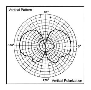
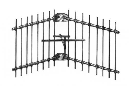
57 BASE STATION VHF CORNER REFLECTOR CP VHF Corner Reflector Antenna Series The Corner Reflector Antennas are available in VHF, UHF, 700/ 800/900MHz configurations. These antennas have an extremely good front-to-back ratio. They are broadband and are great for point-to-point applications. Performance is constant throughout the band. Each antenna has a rugged design to withstand harsh environmental conditions. Single Dipole mounted in the front of a 90º reflector, providing good directivity and a very high front-to-back ratio. These antennas have ultra-low VSWR ratings, and will not exceed 2.0:1 VSWR ratio with 0.5 (13mm) of radial ice. The mounting hardware supplied will permit either vertical or horizontal polarization DC ground for lightning protection Heavy Duty versions are available, but please contact a Comprod Technical support technician for consultation MHz HD Electrical Specifications HD HD Frequency Range, MHz Nominal Gain, dbd Bandwidth: 1.5:1 VSWR, MHz 15% 15% 15% 15% Polarization Vert. or Horiz. Vert. or Horiz. Vert. or Horiz. Vert. or Horiz. Horizontal Beamwidth (Ver. Pol) 67º 67º 50º 50º Vertical Beamwidth (Ver. Pol) 75º 75º 66º 66º Front to Back, db Pattern Direct. Direct. Direct. Direct. Power Rating, Watts Nominal Impedance, Ohms Lightning Protection DC Ground DC Ground DC Ground DC Ground Standard Termination Type N Male Type N Male Type N Male Type N Male Mechanical Specifications Length, in (mm) 48 (1219) 48 (1219) 72 (1829) 72 (1829) Width, in (mm) 75 (1905) 75 (1905) 120 (3048) 120 (3048) Weight, lbs (kg) 39 (17.7) 57 (25.8) 66 (30) 72 (32.7) Rated Wind Velocity: No Ice, mph (km/h) 100 (161) 140 (225) 100 (161) 140 (225) Rated Wind Velocity: 0.5 (13mm) Ice, mph (km/h) 85 (137) 100 (161) 85 (137) 100 (161) Lateral 100mph wind, lbs (kg) 144 (65) 236 (107) 320 (145) 398 (181) Projected Area ft 2 (m 2 ) 5.3 (0.5) 8.8 (0.82) 11.9 (1.10) 14.8 (1.38) Mounting Information: (clamp included) For pipe size O.D. inch (mm) 2.9 (73) 2.9 (73) 2.9 (73) 2.9 (73) Ice breakers are available. 56
58 VHF CORNER REFLECTOR MHz BASE STATION HD

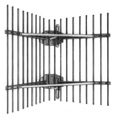
59 BASE STATION 220MHz CORNER REFLECTOR CP 220MHz Corner Reflector Antenna Series The Corner Reflector Antennas are available in VHF, UHF, 700/800/ 900MHz configurations. These antennas have an extremely good front-to-back ratio. They are broadband and are great for point-to-point applications. Performance is constant throughout the band. Each antenna has a rugged design to withstand harsh environmental conditions. Single Dipole mounted in the front of a 90º reflector, providing good directivity and a very high front-to-back ratio. These antennas have ultra-low VSWR ratings, and will not exceed 2.0:1 VSWR ratio with 0.5 (13mm) of radial ice. The mounting hardware supplied will permit either vertical or horizontal polarization. DC ground for lightning protection. Heavy Duty versions are available, but please contact a Comprod Technical support technician for consultation MHz HD Electrical Specifications HD Frequency Range, MHz Nominal Gain, dbd Bandwidth: 1.5:1 VSWR, MHz Polarization Vert. Or Horiz. Vert. Or Horiz. Vert. Or Horiz. Horizontal Beamwidth (Ver. Pol) 67º 67º 50º Vertical Beamwidth (Ver. Pol) 75º 75º 66º Front to Back, db Pattern Direct. Direct. Direct. Power Rating, Watts Nominal Impedance, Ohms Lightning Protection DC Ground DC Ground DC Ground Standard Termination Type N Male Type N Male Type N Male Mechanical Specifications Length, in (mm) 48 (1219) 48 (1219) 72 (1829) Width, in (mm) 75 (1905) 75 (1905) 120 (3048) Weight, lbs (kg) 39 (17.7) 57 (25.8) 55 (30) Rated Wind Velocity: No Ice, mph (km/h) 100 (161) 140 (225) 100 (161) Rated Wind Velocity: 0.5 (13mm) Ice, mph (km/h) 85 (137) 100 (161) 85 (137) Lateral 100mph wind, lbs (kg) 144 (65) 236 (107) 320 (145) Projected Area ft 2 (m 2 ) 5.3 (0.5) 8.8 (0.82) 11.9 (1.10) Mounting Information: (clamp included) For pipe size O.D. inch (mm) 2.9 (73) 2.9 (73) 2.9 (73) 58


60 220MHz CORNER REFLECTOR MHz BASE STATION HD
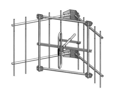
61 BASE STATION UHF CORNER REFLECTOR CP UHF Corner Reflector Antenna Series The Corner Reflector Antennas are available in VHF, UHF, 700/ 800/900MHz configurations. These antennas have an extremely good front-to-back ratio. They are broadband and are great for point-to-point applications. Performance is constant throughout the band MHz Each antenna has a rugged design to withstand harsh environmental conditions. Single or Dual Dipole mounted in the front of a 90º reflector, providing good directivity and a very high front-to-back ratio. The and are highly directive parabolic antenna consisting of a back-firing dipole reflector assembly for increased gain and directivity. These antennas have ultra-low VSWR ratings, and will not exceed 2.0:1 VSWR ratio with 0.5 (13mm) of radial ice. The mounting hardware supplied will permit either vertical or horizontal polarization DC ground for lightning protection Heavy Duty versions are available, but please contact a Comprod Technical support technician for consultation Electrical Specifications Frequency Range, MHz Nominal Gain, dbd Bandwidth: 1.5:1 VSWR, MHz Polarization Vert. or Horiz. Vert. or Horiz. Vert. or Horiz. Horizontal Beamwidth (Ver. Pol) 60º 40º 32º Vertical Beamwidth (Ver. Pol) 45º 34º 18º Front to Back, db Pattern Direct. Direct. Direct. Power Rating, Watts Nominal Impedance, Ohms Lightning Protection DC Ground DC Ground DC Ground Standard Termination Type N Male Type N Male Type N Male Mechanical Specifications Length, in (mm) 30 (762) 48 (1219) 82 (2083) Width, in (mm) 50 (1905) 50 (1905) 41 (1041) Weight, lbs (kg) 22 (10) 42 (19.1) 25 (11.3) Rated Wind Velocity: No Ice, mph (km/h) 125 (201) 125 (201) 100 (161) Rated Wind Velocity: 0.5 (13mm) Ice, mph (km/h) 85 (137) 85 (137) 85 (137) Lateral 100mph wind, lbs (kg) 97 (44) 185 (84) 233 (109) Projected Area ft 2 (m 2 ) 3.6 (0.34) 6.9 (0.64) 8.7 (0.8) Mounting Information: (clamp included) For pipe size O.D. inch (mm) 2.9 (74) 2.9 (74) 2.9 (74) 60

62 UHF CORNER REFLECTOR MHz BASE STATION

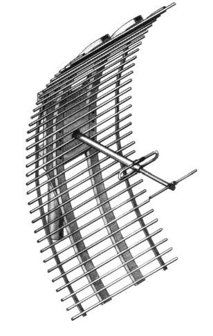
63 BASE STATION PARABOLIC DIRECTIONAL ANTENNA CP Parabolic Reflector Series Antennas The Radeflector is a SRSP-507 Category A compliant antenna. These antennas have an extremely good front-to-back ratio. They are broadband and are great for point-to-point applications where restrictions on beam width are present. Performance is constant throughout the band. SRSP-507 Category A Compliant Mechanical resonance reducing design Each antenna has a rugged design to withstand harsh environmental conditions. The is a highly directive parabolic antenna consisting of a back-firing dipole reflector assembly for increased gain and directivity. These antennas have ultra-low VSWR ratings, and will not exceed 2.0:1 VSWR ratio with 0.5 (13mm) of radial ice. The mounting hardware supplied will permit either vertical or horizontal polarization DC ground for lightning protection Black Anodized and Dipole Radome protected versions are available, but please contact a Comprod Technical support technician for consultation B BR MHz Electrical Specifications B BR Frequency Range, MHz Nominal Gain, dbd Bandwidth: 1.5:1 VSWR, MHz Polarization Vert. or Horiz. Vert. or Horiz. Vert. or Horiz. Horizontal Beamwidth (Ver. Pol) Vertical Beamwidth (Ver. Pol) Front to Back, db Pattern Directional Directional Directional Power Rating, Watts Nominal Impedance, Ohms Lightning Protection DC DC DC Standard Termination Type N Male Type N Male Type N Male Mechanical Specifications Length, in (mm) 68 (1727) 68 (1727) 68 (1727) Width, in (mm) 36 (914) 36 (914) 36 (914) Weight, lbs (kg) 49 (22.3) 49 (22.3) 51 (23.2) Rated Wind Velocity: No Ice, mph (km/h) 110 (177) 110 (177) 110 (177) Rated Wind Velocity: 0.5 (13mm) Ice, mph (km/h) 85 (137) 85 (137) 85 (137) Lateral 100 mph wind, lbs (kg) 1.9 (0.46) 1.9 (0.46) 1.9 (0.46) Projected area ft 2 (m 2 ) 4.9 (0.46) 4.9 (0.46) 5 (0.47) Mounting Information: (Clamps incl.)

64 PARABOLIC DIRECTIONAL ANTENNA MHz BASE STATION
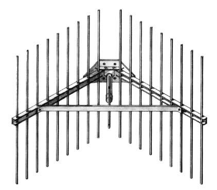
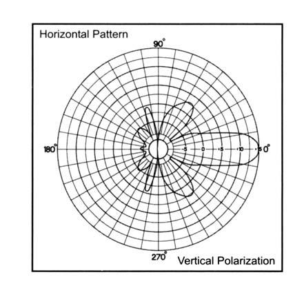
65 BASE STATION LOG PERIODIC ANTENNA CP Log Periodic Series Antennas The Log Periodic Antennas are available in VHF and UHF configurations. These antennas have an extremely good front-to-back ratio. They are wideband and are great for base station or in-building applications. We have had great success with these antennas providing underground coverage within garages. Performance is constant throughout the band. Each antenna has a rugged design to withstand harsh environmental conditions. The mounting hardware supplied will permit either vertical or horizontal polarization DC ground for lightning protection Heavy Duty versions are available, but please contact a Comprod Technical support technician for consultation MHz Electrical Specifications Frequency Range, MHz Nominal Gain, dbd Bandwidth: 1.5:1 VSWR, MHz Polarization Vert. or Horiz. Vert. or Horiz. Vert. or Horiz. Horizontal Beamwidth (Ver. Pol) 106º 106º 75º Vertical Beamwidth (Ver. Pol) 60º 30º 55º Front to Back, db Pattern Direct. Direct. Direct. Power Rating, Watts Nominal Impedance, Ohms Lightning Protection DC Ground DC Ground DC Ground Standard Termination Type N Male Type N Male Type N Male Mechanical Specifications Length, in (mm) 42 (1067) 42 (1067) 60 (1524) Width, in (mm) 44 (1118) 44 (1118) 44.5 (1130) Weight, lbs (kg) 8 (3.6) 8 (3.6) 16.8 (7.8) Rated Wind Velocity: No Ice, mph (km/h) 158 (254) 158 (254) 150 (241) Rated Wind Velocity: 0.5" (13mm) Ice, mph (km/h) 108 (173) 108 (173) 135 (217) Lateral 100mph wind, lbs (kg) 31 (14) 31 (14) 47.5 (21.5) Torsional 100mph wind, lb*ft (kg*m) 56 (7.8) n/a 121 (16.7) Projected Area ft² (m²) 0.86 (0.08) 0.86 (0.08) 1.26 (0.120) Mounting Information: Max Pipe Size. 1" to 2.5" (64mm) 1" to 2.5" (64mm) 1" to 2.5" (64mm) Order Information End Mount Center Mount n/a n/a n/a 64

66 LOG PERIODIC ANTENNA MHz BASE STATION
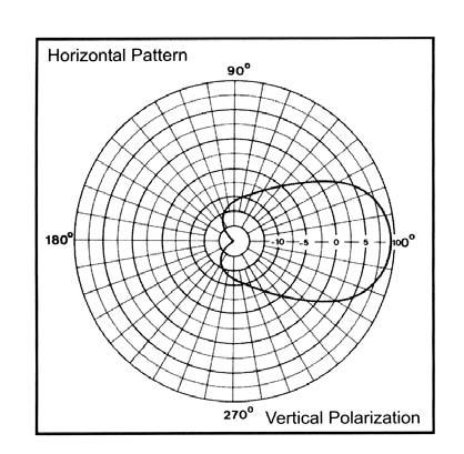
67 BASE STATION LOG PERIODIC ANTENNA CP Log Periodic Series Antennas The Log Periodic Antennas are available in VHF and UHF configurations. These antennas have an extremely good front-to-back ratio. They are wideband and are great for base station or in-building applications. We have had great success with these antennas providing underground coverage within garages. Performance is constant throughout the band. Each antenna has a rugged design to withstand harsh environmental conditions. The mounting hardware supplied will permit either vertical or horizontal polarization DC ground for lightning protection Heavy Duty versions are available, but please contact a Comprod Technical support technician for consultation MHz Electrical Specifications Frequency Range, MHz Nominal Gain, dbd Unity 6.0 Bandwidth: 1.5:1 VSWR, MHz Polarization Vert. or Horiz. Vert. or Horiz. Horizontal Beamwidth (Ver. Pol) n/a 106º Vertical Beamwidth (Ver. Pol) 84º 60º Front to Back, db n/a 20 Pattern Omni-Dir. Uni Direct. Power Rating, Watts Nominal Impedance, Ohms Lightning Protection DC Ground DC Ground Standard Termination Type N Male Type N Male Mechanical Specifications Length, in (mm) 18 (457) 15 (381) Width, in (mm) 14.3 (362) 16 (406) Weight, lbs (kg) 2.6 (1.2) 3.3 (1.47) Rated Wind Velocity: No Ice, mph (km/h) 160 (257) 150 (241) Rated Wind Velocity: 0.5 (13mm) Ice, mph (km/h) 120 (193) 110 (177) Lateral 100mph wind, lbs (kg) 12 (5.4) 14 (6.4) Torsional 100mph wind, lb*ft (kg*m) 6.3 (0.88) 6.4 (0.89) Projected Area ft 2 (m 2 ) 0.44 (0.04) 0.50 (0.05) Mounting Information: Max Pipe Size. 1 to 2.5 (64mm) 1 to 2.5 (64mm) Order Information MHz MHz MHz MHz * *2 n/a * n/a n/a * *2 66


68 LOG PERIODIC ANTENNA MHz BASE STATION
69 BASE STATION DATA ANTENNA CP Data Antenna Series The Data Antenna Series are high quality, high performance, utility grade antennas. We have many different versions of these antennas, but here are a few that showcase the ability of some of our more unique styled antennas. We have developed antennas for point-to-point data transmissions using PCB surrounding hydro meters. We have modified mobile antennas, in order to produce low cost and effective base station antennas. We offer other antennas that maximize performance at no cost. Custom Developed Meet your specific needs Designed for any application as needed by the customer Heavy Duty Versions are available, but please contact a Comprod Technical support technician for consultation BSMO Electrical Specifications BSMO Frequency Range, MHz Nominal Gain, dbi 2.0 Polarization Vertical Pattern Omni Power Rating, Watts 200 Nominal Impedance, Ohms 50 Standard Termination Type N Female* Mechanical Specifications Length, inches (mm) Diameter, inches (mm) Weight, lbs (kg) Radiator Base Contact Mounting * Other Terminations are available. min lowest freq. n/a n/a Stainless Steel ABS, Ultrasonic Brass Insert Spring Loaded, Gold Plated BSMOLC w/n-female 68
70 NOTES: 69
71 CLAMPS 70

72 CLAMPS Our standard offering of clamps has evolved over the last 30 years and is among one of the best in the industry. Not only do we offer the following standard clamp designs, but we have developed many custom one-off s for several customers unique installation requests. Most of our clamps are fabricated using hot-dipped galvanized high grade steel, that is incorporating oversized u-bolts and fastening hardware. We also offer stainless steel versions as an alternative in extremely corrosive environments. CLAMPS 71


73 90º PIPE-TO-PIPE CLAMPS Model 1st Pipe 2nd Pipe " to 3.5" dia. 2.25" to 5" dia. 110R " dia. 2.25" to 5" dia " to 3.5 " dia. 1.5" to 3.5" dia. 115R " dia. 1.5" to 3.5" dia " to 2.5" dia. 1.0" to 2.4" dia " dia. 1.0" to 2.4" dia " dia. 1.0" dia "dia. 0.75" dia "dia. 1.9" dia dia. 1.0 to 2.4 dia dia. 1.5 dia R R


74 PARALLEL PIPE-TO-PIPE Model 1st Pipe 2nd Pipe " to 3.5" dia. 1.5" to 3.5" dia " to 5" dia. 2.5" to 5" dia " to 3.5" dia. 1.5" to 3.5" dia. 112L " to 5" dia. 2.25" to 5" dia. 112M " to 3.5" dia. 2.25" to 5" dia " dia " dia " dia. 1.5" to 2.0" dia " dia. 0.75" to 2.375" dia. 167B " dia. 0.75" to 2.375" dia. CLAMPS L M B-85 73


75 PARALLEL OR 90º PIPE-TO-PIPE Model 1st Pipe 2nd Pipe " to 2.88" dia. 0.88" to 2.88" dia to 2.4 dia. 1.0 to 2.4 dia to 2.4 dia. 1.0 to 2.4 dia CLAMPS PIPE-TO-FLAT SURFACE (or wood pole) Model Pipe O.D. 115P " to 3.5" dia. 115W to 3.5 dia to 1.5 dia to 3.5 dia P W
76 PARALLEL PIPE-TO-ANGLE Model 1st Pipe Angle " to 3.5" dia. 8" x 8" max. 60º 113L " to 5.0" dia. 8" x 8" max. 60º " to 3.5 " dia. 8" x 8" max. 90º 116L " to 5.0" dia. 8" x 8" max. 90º " to 3.5" dia. 5" x 5" max. 60º 133L " to 5.0" dia. 5" x 5" max. 60º " to 3.5" dia. 5" x 5" max. 90º 136L " to 5.0" dia. 5" x 5" max. 90º " to 3.5" dia. 3" x 3" max. 60º 163L " to 5.0" dia. 3" x 3" max. 60º " to 3.5" dia. 3" x 3" max. 90º 166L " to 5.0" dia. 3" x 3" max. 90º CLAMPS L L L L L L-85 75

77 90º PIPE-TO-ANGLE Model Pipe Angle " to 3.5" dia. 5"x 5" max. 60º " to 3.5" dia. 5"x 5" max. 90º " to 3.5" dia. 8"x 8" max. 60º " to 3.5" dia. 8"x 8" max. 90º " to 3.5" dia. 3"x 3" max. 60º " to 3.5" dia. 3"x 3" max. 90º CLAMPS Pipe Angle Pipe to Angle 1.5" to 3.5" dia. 3.5"x 3.5" max. 60º Pipe to Angle 1.5" to 3.5" dia. 2.75"x 2.75" max. 90º Pipe Angle Pipe to Pipe 1.5" to 3.5" dia. 1.5" to 3.5" dia. 76
78 OMNIDIRECTIONAL PIPE-TO-ANGLE Model Pipe Angle " to 3.5" dia. 3"x 3" max. 60º " to 3.5" dia. 5"x 5" max. 60º " to 3.5" dia. 8"x 8" max. 60º " to 3.5" dia. 3"x 3" max. 90º " to 3.5" dia. 5"x 5" max. 90º " to 3.5" dia. 8"x 8" max. 90º CLAMPS OMNIDIRECTIONAL PIPE-TO-PIPE Model 1st Pipe 2nd Pipe " to 2.38" dia. 0.75" to 2.38" dia. PIPE-TO-FLAT SURFACE Model Pipe " dia " dia. 77


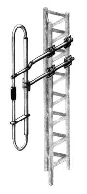
79 SIDE-MOUNTING ASSEMBLY Model Tower Leg Holder Section Tower "x 5" max. 60º 1.5" to 3.5" 60º * "x 8" max. 60º 1.5" to 3.5" 60º * "x 3" max. 60º 1.5" to 3.5" 60º * 3 CLAMPS EACH KIT INCLUDES 4 Clamps Model Al pipe 2 #40 x 10 feet 4 Clamps Model Al pipe 2 #40 x 10 feet 4 Clamps Model Al pipe 2 #40 x 10 feet EACH KIT INCLUDES Clamps Model Al pipe 2 #40 x 10 feet Clamps Model Al pipe 2 #40 x 10 feet Clamps Model Al pipe 2 #40 x 10 feet Model Tower Leg Holder Section Tower "x 5" max. 90º 1.5" to 3.5" 90º * 5" "x 8" max. 90º 1.5" to 3.5" 90º * 8" "x 3" max. 90º 1.5" to 3.5" 90º * 3" 78
80 SIDE-MOUNTING ASSEMBLY Model Tower Leg Holder Section Tower " to 3" AI. pipe 1.9" O.D. x 120" 1.50" " to 3" AI. pipe 1.9" O.D. x 60" 1.50" " to 3" AI. pipe 2.375" O.D. x 120" 2.00" EACH KIT INCLUDES 4 Clamps Model Support pipes 1.5 #40 x 10 feet 4 Clamps Model Support pipes 1.5 #40 x 5 feet 4 Clamps Model Support pipes 2 #40 x 10 feet CLAMPS YAGI HOLDER KIT Model Tower Leg Holder Section " to 3.5" AI. angle 1.5" x 1.5" x.1875" 79
81 IN-BUILDING 80

82 IN-BUILDING ANTENNAS IN-BUILDING ANTENNA SYSTEMS Our in-building antenna systems are very unique in the industry. All of our antennas are by-products of our customers needs, subway projects, high-rise in-building systems, nuclear power plants, correction facilities, and many more. Our line of antenna system solutions incorporates single, dual, triple, quad, and 5-band frequency specifications. Our in-house R&D team works with our customers to develop antennas that meet their exact project needs. These antennas are offered in a wide range of radomes, low-profile, 6200 Kydex Fire-Retardant material, ABS High- Impact, aluminum, and custom colors. We can provide antenna systems, spliters, couplers, taps, cables, connectors, BDAs, and many other necessary components. In our arsenal of antenna products we offer a solution for many applications. We offer many different versions and frequencies; the following antenna products are just a sampling. We encourage you and your team to contact us for either technical support or to request a potential new design. Please call for a custom antenna design or to see our other available models. IN-BUILDING 81

83 MULTI-BAND ANTENNAS Multi-Band In-Building Antennas Our antennas are designed, manufactured and integrated with the most innovative and highly specialized processes, providing our customers with a solid, long-lasting solution for their in-building applications. Our multi-band antennas are one-of-a-kind and many are the only ones available in the world. They can cover more than three bands in most cases and provide an idea of some of our products. IN-BUILDING We offer a wide variety of our antennas with Fire Retardant 6200 Kydex radomes. These radomes are designed for use in in-building applications and public transport vehicles such as underground trains, vans, buses, and trains. They meet the recommended fire safety practices of both the Federal Transit Administration (FTA) and the Federal Rail Administration (FRA) for smoke emission and flammability as tested under ASTM E-662 and ASTM E-162. Our antennas have been installed all over the world. Some typical installations are Nuclear Power Plants, Correction Centers, Tunnels, High-Rise Buildings, SubWays, Light & Heavy Rail, Power Plants, High-Security Office networks, and Mine Shafts. F F Electrical Specifications F F Frequency Range, MHz / Nominal Gain, dbd Unity Unity Bandwidth: 1.5:1 VSWR, MHz n/a n/a n/a n/a n/a Full Band n/a n/a Polarization Vertical Vertical Pattern Omni Omni Power Rating, Watts Nominal Impedance, Ohms Radome 6200 Kydex 6200 Kydex Standard Termination N Female 3' Jumper - N Female Mechanical Specifications Length, in (mm) 2 (51) 2 (51) Diameter, in (mm) 4.5 (114) 4.5 (114) Weight, lbs (kg) (0.169) (0.169) Min. Ground Plane Size, in (mm) 8 x 8 (203 x 203) 8 x 8 (203 x 203) Mounting Information Not Included Not Included Please call for other available models. 82
84 MULTI-BAND ANTENNAS F-3941 IN-BUILDING F F-3741NGP 83

85 MULTI-BAND ANTENNAS Multi-Band In-Building Antennas Our antennas are designed, manufactured and integrated with the most innovative and highly specialized processes, providing our customers with a solid, long-lasting solution for their in-building applications. Our multi-band antennas are one-of-a-kind and many are the only ones available in the world. They can cover more than three bands in most cases and provide an idea of some of our products. IN-BUILDING We offer a wide variety of our antennas with Fire Retardant 6200 Kydex radomes. These radomes are designed for use in in-building applications and public transport vehicles such as underground trains, vans, buses, and trains. It meets the recommended fire safety practices of both the Federal Transit Administration (FTA) and the Federal Rail Administration (FRA) for smoke emission and flammability as tested under ASTM E-662 and ASTM E-162. Our antennas have been installed all over the world. Some typical installations are Nuclear Power Plants, Correction Centers, Tunnels, High-Rise Buildings, SubWays, Light & Heavy Rail, Power Plants, High-Security Office networks, and Mine Shafts Electrical Specifications Frequency Range, MHz Nominal Gain, dbd Unity Unity Unity Unity Bandwidth: 1.5:1 VSWR, MHz Bandwidth: 2.0:1 VSWR, MHz Polarization Vertical Vertical Vertical Vertical Pattern Omni Omni Omni Omni Power Rating, Watts Nominal Impedance, Ohms Radome ABS / 6200 Kydex ABS / 6200 Kydex ABS / 6200 Kydex ABS / 6200 Kydex Color Grey / White Grey / White Grey / White Grey / White Standard Termination UHF / BNC UHF / BNC N Female N Female Mechanical Specifications Length, in (mm) 4.0 (102) 3.0 (76) 3.15 (80) 2.0 (51) Length, in (mm) 21.0 (533) 11.0 (279) 9.3 (236) 4.5 (114) Width, in (mm) 3.0 (76) 3.25 (83) n/a n/a Weight, lbs (kg) 2.1 (0.945) 1.0 (0.45) 2.5 (1.15) (0.169) Min. Ground Plane Size, inches (mm) 36 X 48 (914 X 1219) 20 X 16 (508 X 406) 14 X 14 (355 X 355) 10 X 10 (254 X 254) Please call for other available models. 84


86 MULTI-BAND ANTENNAS IN-BUILDING

87 IN-BUILDING ANTENNAS In-Building Antennas Our antennas are designed, manufactured and integrated with the most innovative and highly specialized processes, providing our customers with a solid, long-lasting solution for their in-building applications. Our multi-band antennas are one-of-a-kind and many are the only ones available in the world. They are able to cover more than three bands in most cases and provide an idea of some of our products. IN-BUILDING We offer a wide variety of our antennas with Fire Retardant 6200 Kydex radomes. These radomes are designed for use in in-building applications and public transport vehicles such as underground trains, vans, buses, and trains. They meet the recommended fire safety practices of both the Federal Transit Administration (FTA) and the Federal Rail Administration (FRA) for smoke emission and flammability as tested under ASTM E-662 and ASTM E-162. Our antennas have been installed all over the world. Some typical installations are Nuclear Power Plants, Correction Centers, Tunnels, High-Rise Buildings, SubWays, Light & Heavy Rail, Power Plants, High-Security Office networks, and Mine Shafts. F-3953 Electrical Specifications F-3987 F-3953 Frequency Range, MHz Nominal Gain, dbd Unity Unity Bandwidth: 1.5:1 VSWR, MHz (2:0:1) / Polarization Vertical Vertical Pattern Omni Omni Power Rating, Watts Nominal Impedance, Ohms Radome Aluminum Polycarbonate Color Black or White Black or White Lightning Protection DC Ground DC Ground Standard Termination NMO N - Male Mechanical Specifications Length, in (mm) 6.75 (171) 7.0 (178.5) Diameter, in (mm) 0.5 (12.75) (15.93) Weight, lbs (kg) n/a n/a Min. Ground Plane Size, in (mm) n/a 8 x 8 (203 x 203) Mounting Information Mobile Mount Included Please call for other available models. 86
88 IN-BUILDING ANTENNAS F-3941 IN-BUILDING F

89 MULTI-BAND ANTENNAS Multi-Band In-Building Antennas Our antennas are designed, manufactured and integrated with the most innovative and highly specialized processes, providing our customers with a solid, long-lasting solution for their in-building applications. Our multi-band antennas are one-of-a-kind and many are the only ones available in the world. They are able to cover more than three bands in most cases and provide an idea of some of our products. IN-BUILDING We offer a wide variety of our antennas with Fire Retardant 6200 Kydex radomes. These radomes are designed for use in in-building applications and public transport vehicles such as underground trains, vans, buses, and trains. It meets the recommended fire safety practices of both the Federal Transit Administration (FTA) and the Federal Rail Administration (FRA) for smoke emission and flammability as tested under ASTM E-662 and ASTM E-162. Our antennas have been installed all over the world. Some typical installations are Nuclear Power Plants, Correction Centers, Tunnels, High-Rise Buildings, SubWays, Light & Heavy Rail, Power Plants, High-Security Office networks, and Mine Shafts. F-3749 The F-3741 has been designed for mounting on a concrete surface. This is a requirement for meeting full bandwidth specification. Electrical Specifications F-3741* F-3749* F Frequency Range, MHz VHF / UHF / VHF / UHF / / / Nominal Gain, dbd Unity Unity Unity Bandwidth: 1.5:1 VSWR, MHz n/a n/a n/a n/a n/a n/a n/a Polarization Vertical Vertical Vertical Pattern Omnidirectional Omnidirectional Omnidirectional Power Rating, Watts Total Nominal Impedance, Ohms Radome Polycarbonate 6200 Kydex 6200 Kydex Color Black White White Lightning Protection DC Ground DC Ground DC Ground Standard Termination N Male N Female N Female Mechanical Specifications Length, inch (mm) (286.88) 9.78 (249) 5.5 (140) Diameter, inch (mm) 0.65 (16.575) 7.0 (178.5) 9.8 (248) Weight, lbs (kg) n/a n/a 2.5 (1.15) Min. Ground Plane Size, inches (mm) Included 14 x 14 (357 x 357) 14 x 16 (356 x 406) * 700MHz is also available ** Comes with pigtail and N Male connector. Please call for more available models. Specify frequencies when ordering. 88


90 MULTI-BAND ANTENNAS F-3749 F-3749A** IN-BUILDING F Optional Mounting Bracket F Optional Mounting Bracket F
91 MOBILE/TRANSIT 90

92 MOBILE AND TRANSIT ANTENNAS Our Mobile and Transit antenna lines are the best and most unique products in the market. All of our products are suited for Government and Utility applications, long-term, hasslefree installations. We use Stainless Steel whips, incorporate High Impact ABS, and Gold Plated spring loaded contacts when ever possible, insuring long-term reliability and performance. Our multi-band antennas have been developed for transmitting and receiving Data, Voice, and Video. Ideal for applications that require install and forget capabilities. We have developed many Wideband and Full-Band VHF, UHF, and 700/800/900MHz antenna models. Please call for more details. Transit Dual Band Mobile Antenna Frequency Gain Options Model Lo-Band VHF 220 UHF DUAL Unity 2dB 3dB 5dB NGP Black W/ Spring B B B S B S S B S B S B S B B B B B B MOBILE/TRANSIT 91
93 LOW BAND 27-54MHz Performance: Unity gain, base loaded antenna with a power handling capacity of 200 Watts. Stylish and Durable: These antennas are manufactured using the best corrosion resistant materials and finishes available. The base is triple plated chrome brass with a large insert moulded low loss coil form and a spring-loaded gold plated contact. Broadband: The large diameter coil form used in the construction of the loading coil allows for a wider operational bandwidth and better matching characteristics. Weatherproof: O-ring seals and overlap construction keep moisture out of the antenna Series Standard Mounting: These antennas mate with the standard TAD / NMO type mount, providing an excellent moisture seal even when the antenna is removed. MOBILE/TRANSIT Electrical Specifications Frequency Range, MHz Gain Unity Impedance, Ohms 50 Power Rating, Watts 200 VSWR 1.5:1 Bandwidth 2% of center freq. Mechanical Specifications Radiator: Brite A Tapered S.S., 125 dia. Black B Tapered S.S., 100 dia. Base ABS, spring loaded contact Length, in 52 Maximum Mounting Std. Motorola type, 3/4 Ordering Information Frequency Brite Black 27-31MHz A B MHz A B MHz A B MHz A B MHz A B-5 92
94 VHF / 3dB MHz Performance: The 5/8-wave antenna provides 3dB of gain and is designed for heavy-duty service. Durable: The 5/8-wave radiator and integral base-loading coil are fabricated from 17-7PH spring tapered stainless steel. Reliable: This antenna will withstand severe flexing without taking an undesirable "set". Versatile: The antenna is supplied full length with a set of field cutting instructions. Standard Mounting: The antenna is shipped with the mount, 17ft. (5.2m) RG-58U and PL-259 connector. Electrical Specifications Frequency Range, MHz Gain, db 3 Impedance, Ohms 50 Power Rating, Watts 150 Bandwidth / VSWR 4MHz / 1.5:1 7MHz / 2.0:1 Mechanical Specifications Radiator Length, in Mounting, in 17-7PH S.S. 55 Maximum 5/16 Standard Series MOBILE/TRANSIT Ordering Information Description Model Complete antenna including Base, 3/8" Snap mount, 17ft coax and PL-259 conn Whip ass'y and ferrule only

95 1/4 WAVE BROADBAND MHz Performance: These antennas provide unity gain in a very broadband design for extra heavy-duty service. Stylish and Durable: These antennas are manufactured using the finest corrosion resistant materials and finishes available. They come with an integrated shock spring and a heavy duty S.S. whip that is designed to withstand severe shock. Reliable: The ABS base has an ultrasonically welded brass insert and a gold plated spring loaded contact. Broadband: This antenna provides 24MHz of bandwidth at VHF frequencies and 100MHz of bandwidth at UHF frequencies. Standard Mounting: All base loaded antennas mate with the standard TAD / NMO type mount Series MOBILE/TRANSIT Electrical Specifications Frequency Range, MHz Gain Unity Impedance, Ohms 50 Power Rating, Watts 150 Bandwidth / VSWR VHF / 2.0:1 UHF / 2.0:1 Mechanical Specifications Radiator: Brite A Tapered S.S. whip.,125 Black B Tapered S.S. whip.,100 Base Ultrasonic brass insert Contact Spring loaded, gold plated Length, in (mm) 21.5 (55) at 138MHz Mounting Motorola type, 3/4 Ordering Information Description Model Brite finish, triple plated chrome A Black finish B 94
96 LOW COST MHz Performance: These antennas provide unity gain in a wideband design for heavy-duty service. Stylish and Durable: These antennas are manufactured using the best corrosion resistant materials and finishes available. Triple plated chrome or black finishes available. Reliable: The ABS base has an ultrasonically welded brass insert and a gold plated spring loaded contact. Versatile: They are shipped with a 20" whip that can be cut to any frequency between 136 and 960MHz. They can also be supplied cut and tested to a specific frequency at no extra charge. Standard Mounting: These antennas mate with the standard TAD / NMO type mount, providing an excellent moisture seal even when the antenna is removed Series Electrical Specifications Frequency Range, MHz Gain Unity Impedance, Ohms 50 Power Rating, Watts 200 VSWR 1.5:1 Bandwidth / VSWR VHF / 2.0:1 UHF / 2.0:1 Mechanical Specifications Radiator: Brite A Tapered S.S., 100 dia. Black B Tapered S.S., 100 dia. Base ABS Length, in 20 Maximum Mounting Std. Motorola type, 3/4 MOBILE/TRANSIT Ordering Information Description Model Brite finish, triple plated chrome A Black finish B 95
97 1/4 WAVE / VHF UHF TRUNKING MHz Performance: These antennas provide unity gain in a wideband design for heavy-duty service. Stylish and Durable: These antennas are manufactured using the best corrosion resistant materials and finishes available. Triple plated chrome or black finishes available. Reliable: The ABS base has an ultrasonically welded brass insert and a gold plated spring loaded contact. Versatile: They are shipped with a 20" whip that can be cut to any frequency between 136 and 960MHz. They can also be supplied cut and tested to a specific frequency, at no extra charge Series Standard Mounting: These antennas mate with the standard TAD / NMO type mount, providing an excellent moisture seal even when the antenna is removed. MOBILE/TRANSIT Electrical Specifications Frequency Range, MHz Gain Unity Impedance, Ohms 50 Power Rating, Watts 150 Bandwidth / VSWR VHF / 2.0:1 UHF / 2.0:1 Mechanical Specifications Radiator Stainless Steel Base ABS, Ultrasonic brass insert Contact Spring loaded contact Length, in 20 maximum Mounting Standard Motorola type, 3/4 Ordering Information Description Model Brite finish, triple plated chrome A Black finish B 96


98 VHF WIDEBAND / 2dB MHz No Ground Plane Antenna Performance: This broadband 1/2-wave antenna provides 2.0dB of gain over its operating bandwidth. No ground plane antenna. Stylish and Durable: The antennas are manufactured using the best corrosion resistant materials and finishes available. The base is triple plated chrome brass with a large insert moulded low loss coil form and a spring loaded, gold plated contact. Weatherproof: O-ring seals and overlap construction keep moisture out of the antenna. Standard Mounting: All base loaded antennas mate with the standard TAD / NMO type mount. Electrical Specifications Frequency Range, MHz Gain, db 2.0 Impedance, Ohms 50 Power Rating, Watts 75 Bandwidth / VSWR 11 VHF / 1.5:1 19 VHF / 2.0:1 Mechanical Specifications Radiator 17-7 PH S.S. Base ABS, spring loaded contact Length, in 52 Maximum Mounting Standard Motorolla type, 3/ Series MOBILE/TRANSIT Ordering Information Description MHz Antenna Brite finish With shock spring S 97
99 VHF / 3dB MHz Performance: 3dB gain is achieved with these premium antennas by featuring a 5/8-wave whip with a base loaded matching coil. Stylish and Durable: These antennas are manufactured using the finest corrosion resistant materials and finishes available. The base is triple plated chrome brass with a large insert moulded low loss coil form and a spring loaded, gold plated contact. Broadband: The large diameter coil form used in the construction of the loading coil allows for a wider operational bandwidth and better matching characteristics. Weatherproof: O-ring seals and overlap construction keep moisture out of the antenna. Standard Mounting: All base loaded antennas mate with the standard TAD / NMO type mount Series MOBILE/TRANSIT Electrical Specifications Frequency Range, MHz Gain, db 3 Impedance, Ohms 50 Power Rating, Watts 200 VSWR 1.5:1 Bandwidth, MHz 6 Mechanical Specifications Radiator: Brite A Tapered S.S. whip.,125 Black B Tapered S.S. whip.,100 Base ABS, spring loaded contact Length, in 55 whip Mounting Standard TAD / NMO type Ordering Information Description Model Brite finish, triple plated chrome A Black finish B To order with shock spring, add suffix S to part number. Example: AS. 98
100 UHF / 3dB MHz Performance: This broadband 5/8-wave antenna provides 3.0dB of gain over its operating bandwidth. Stylish and Durable: The antennas are manufactured using the best corrosion resistant materials and finishes available. The base is triple plated chrome brass with a large insert moulded low loss coil form and a spring loaded, gold plated contact. Weatherproof: O-ring seals and overlap construction keep moisture out of the antenna. Standard Mounting: All base loaded antennas mate with the standard TAD / NMO type mount Series Electrical Specifications Frequency Range, MHz Gain, db 3.0 Impedance, Ohms 50 Power Rating, Watts 200 Bandwidth / VSWR 20MHz / 1.5:1 Mechanical Specifications Radiator: Brite A S.S. whip., 100 Black B S.S. whip., 100 Base ABS, spring loaded contact Length, in 21 whip Mounting Standard TAD / NMO type MOBILE/TRANSIT Ordering Information Frequency Brite Black MHz A B MHz A B MHz A B MHz A B MHz A B-5 To order with shock spring, add suffix S to part number. Example: 75AS-3. 99
101 800 LOW COST MHz Performance: 3dB gain is achieved with these premium antennas by featuring a 5/8 wave over a 1/4 wave open coil design. Stylish and Durable: These antennas are manufactured using the finest corrosion resistant materials and finishes available. Triple plated chrome or black finishes available. Reliable: The ABS base has an ultrasonically welded brass insert and a leaf spring-loaded contact for long-term reliability. Standard Mounting: These antennas mate with the standard TAD / NMO type mount, providing an excellent moisture seal even when the antenna is removed Series MOBILE/TRANSIT Electrical Specifications Frequency Range, MHz Gain, db 3.0 Impedance, Ohms 50 Power Rating, Watts 200 Bandwidth / VSWR 70MHz / 2.0:1 or less Mechanical Specifications Radiator: Base Contact Length, in Mounting Brite A Black B S.S. whip., 100 Ultrasonic brass insert Leaf Design 14 at lowest freq. Standard TAD / NMO type Ordering Information Frequency Brite Black MHz A B MHz A B MHz A B-3 100
102 CELLULAR TRUNKING / 3dB MHz Performance: 3dB gain is achieved with these premium antennas by featuring a 5/8 wave over a 1/4 wave design. Stylish and Durable: These antennas are manufactured using the finest corrosion resistant materials and finishes available. Triple plated chrome or black finishes available. Reliable: The ABS base has an ultrasonically welded brass insert and a gold plated spring-loaded contact for long-term reliability. Standard Mounting: These antennas mate with the standard TAD / NMO type mount, providing an excellent moisture seal even when the antenna is removed Series Electrical Specifications Frequency Range, MHz Gain, db 3.0 Impedance, Ohms 50 Power Rating, Watts 200 Bandwidth / VSWR 70MHz / 2.0:1 or less Mechanical Specifications Radiator: Brite A Black B Base Contact Length, in Mounting Stainless Steel ABS, Ultrasonic brass insert Spring loaded, gold plated 14 at lowest freq. Standard TAD / NMO type MOBILE/TRANSIT Ordering Information Frequency Brite Black MHz A B MHz A B MHz A B-3 101
103 CELLULAR TRUNKING / 3dB CLOSED COIL MHz Performance: 3dB gain is achieved with these premium antennas by featuring a 5/8 wave over a 1/4 wave closed coil design. Stylish and Durable: These antennas are manufactured using the finest corrosion resistant materials and finishes available. Triple plated chrome or black finishes available. Reliable: The ABS base has an ultrasonically welded brass insert and a gold plated spring-loaded contact for long-term reliability. Standard Mounting: These antennas mate with the standard TAD / NMO type mount, providing an excellent moisture seal even when the antenna is removed Series MOBILE/TRANSIT Electrical Specifications Frequency Range, MHz Gain, db 3.0 Impedance, Ohms 50 Power Rating, Watts 200 Bandwidth / VSWR 70MHz / 2.0:1 or less Mechanical Specifications Radiator: Base Contact Length, in Mounting Brite A Black B Stainless Steel ABS, Ultrasonic brass insert Spring loaded, gold plated 14 at lowest freq. Standard TAD / NMO type Ordering Information Frequency Brite Black MHz B MHz B MHz B-3 102

104 CELLULAR TRUNKING / 3.5dB CLOSED COIL MHz High Performance: A full 3.5dB gain is achieved in this antenna by featuring a 5/8 wave over a 1/2 wave design. Stylish and Durable: The antennas are manufactured using the best corrosion resistant materials and finishes available. It comes with an integrated shock spring and a heavy-duty stainless steel whip that is designed to withstand severe shock without suffering permanent damage. It is available in triple plated chrome or black finish. Reliable: The ABS base has an ultrasonically welded brass insert and a gold plated spring loaded contact. The silver plated matching coil is fully enclosed to ensure years of dependable service. Weatherproof: O-ring seals and overlap construction keep moisture out of the antenna. Standard Mounting: All base loaded antennas mate with the standard TAD / NMO type mount Series Electrical Specifications Frequency Range, MHz Gain, db 3.5 Impedance, Ohms 50 Power Rating, Watts 200 Bandwidth / VSWR 70MHz / <2.0:1 Mechanical Specifications Radiator: Brite A Black B Matching coil Base Contact Length, in Mounting Stainless Steel Silver plated enclosed coil ABS,spring loaded contact Gold plated, spring loaded 18 at lowest freq. Standard TAD / NMO type MOBILE/TRANSIT Ordering Information Frequency Brite Black MHz A B MHz A B MHz A B-3 103
105 ELEVATED FEED / 3dB MHz Performance: 3dB gain is achieved with this antenna by featuring a 5/8 wave over a 1/4 wave design with an elevated feed point. This antenna requires no ground plane as a result of its collinear design. Safety: The elevated feed point design keeps the RF signals above and away from the passenger compartment. Elegance: This elegant black antenna gives a sleek appearance that blends well with the exterior treatments of most late model vehicles. Dependability: The antenna features a built-in shock spring and a spring-loaded contact for long-term dependability. Standard Mounting: These antennas mate with the standard Motorola type mount, providing an excellent moisture seal even when the antenna is removed Series MOBILE/TRANSIT Electrical Specifications Frequency Range, MHz Gain, dbd 3.0 Impedance, Ohms 50 Power Rating, Watts 200 Bandwidth / VSWR 70MHz / 2.0:1 or less Mechanical Specifications Radiator Base Contact Length, in Mounting Finish Black Stainless Steel Open coil Solid brass base 23 at lowest freq. Standard TAD / NMO type Black Ordering Information Frequency Black finish MHz MHz MHz

106 DUAL BAND ANTENNAS MHz Performance: Our premium dual band antennas featuring heavy duty design and ultra performance. Perfect for both voice and data transmission. These antennas are ultra wide in bandwidth. Stylish and Durable: These antennas are manufactured using the finest corrosion resistant materials and finishes available. The antenna is low profile, extremely rugged, and ideal for commercial applications. Weatherproof: O-ring seals and overlap construction keep moisture out of the antenna. Standard Mounting: All base loaded antennas mate with the standard TAD / NMO type mount Series Electrical Specifications Frequency (Full Band) / Gain Unity Impedance, Ohms 50 Power Rating, Watts 200 Bandwidth / VSWR Full Band <2.2:1 Mechanical Specifications Radiator Stainless Steel Base ABS, Ultrasonic Brass Insert Contact Gold plated spring loaded Length, in 4 Mounting Standard TAD / NMO type Finish Black MOBILE/TRANSIT 105

107 DUAL BAND ANTENNAS MHz Performance: Our premium dual band antennas featuring heavy duty design and ultra performance. Perfect for both voice and data transmission. These antennas are ultra wide in bandwidth. Stylish and Durable: These antennas are manufactured using the finest corrosion resistant materials and finishes available. The antenna is low profile, extremely rugged, and ideal for commercial applications. Weatherproof: O-ring seals and overlap construction keep moisture out of the antenna. Standard Mounting: All base loaded antennas mate with the standard TAD / NMO type mount Series Electrical Specifications Frequency (Full Band) / / Gain Impedance, Ohms Power Rating, Watts Bandwidth / VSWR Full Band <2.0:1 Full Band <2.0:1 MOBILE/TRANSIT Mechanical Specifications Base ABS ABS Contact Gold plated spring loaded Gold plated spring loaded Length, in 3 3 Mounting Standard TAD / NMO type Standard TAD / NMO type Finish Brite Black 106

108 DUAL BAND ANTENNAS MHz Performance: Our premium dual band antennas featuring heavy duty design and ultra performance. Perfect for both voice and data transmission. These antennas are ultra wide in bandwidth. Stylish and Durable: These antennas are manufactured using the finest corrosion resistant materials and finishes available. The antenna is low profile, extremely rugged, and ideal for commercial applications. Weatherproof: O-ring seals and overlap construction keep moisture out of the antenna. Standard Mounting: All base loaded antennas mate with the standard TAD / NMO type mount Series Electrical Specifications Frequency (Full Band) / / Gain, dbd Unity Unity Impedance, Ohms Power Rating, Watts Bandwidth / VSWR <2.0:1 <2.0:1 Mechanical Specifications Radiator Polyester Coated Brass Polyester Coated Brass Base ABS, Ultrasonic, Brass insert ABS, Ultrasonic, Brass insert Contact Gold Plated Spring Loaded Gold Plated Spring Loaded Length, in 2-3/4 2-3/4 Mounting Standard TAD / NMO type Standard TAD / NMO type Finish Black / White Black / White MOBILE/TRANSIT 107
109 DUAL BAND ANTENNAS MHz Performance: Our premium dual band antennas featuring heavy duty design and ultra performance. Perfect for both voice and data transmission. These antennas are ultra wide in bandwidth. Stylish and Durable: These antennas are manufactured using the finest corrosion resistant materials and finishes available. The antenna is low profile, extremely rugged, and ideal for commercial applications. Weatherproof: O-ring seals and overlap construction keep moisture out of the antenna. Standard Mounting: All base loaded antennas mate with the standard TAD / NMO type mount Series Electrical Specifications Frequency (Full Band) / / Gain, dbd Impedance, Ohms Power Rating, Watts Bandwidth / VSWR <2.0:1 <2.0:1 MOBILE/TRANSIT Mechanical Specifications Base ABS ABS Contact Gold Plated Spring Loaded Gold Plated Spring Loaded Length, in 4 4 Mounting Standard TAD / NMO type Standard TAD / NMO type Finish Brite Black / White 108
 412M-75 Stainless Steel Trunk Groove Mounting Bracket")


110 MOBILE ANTENNAS / ACCESSORIES MMM MMNMO BSMN TMBM Whip Adapter Black Whip Adapter Chrome MGAS MGLAS Battery Tap A1001A Stainless Steel Trunk Groove Mounting Bracket (3/8" hole) 412M-75 Stainless Steel Trunk Groove Mounting Bracket (3/4" hole) Rubber Hole Plug / 3/8" Hole Diameter Universal Base Mount Straight Whip (24" Length) + 5/16-24 Thread Adapter Unity Gain Ae. / Whip and Base ( ) Cable Kit / 15ft of RG-58U + PL UG-175U Magnet Mount Kit, Motorola base, 12 ft. RG58A/U, PL Magnet Mount Kit, 5/16" stud mount, 12 ft. RG58A/U, PI Trunk Mount Kit, Motorola base, 12 ft. RG58A/U, PL Trunk Mount Kit, 5/16" stud mount, 12 ft. RG58A/U, PI C-Mount (3/8"-3/4") c/w 17 ft. RG58A/U, PL Rubber Hole Plug for 7/8" hole diameter MMNMO Mirror Mount Kit, Motorola base, 12 ft. RG-58A/U, PL-259 BSMN Mirror Mount, Motorola base, UHF Connector WAB Whip Adapter, Black WAC Whip Adapter, Chrome A1001A Battery Tap (5 Individually packed) MOBILE/TRANSIT 109


.")
111 MOBILE ANTENNAS / ACCESSORIES THICK BODY MOUNTS UTBM Mount Terminates as Mini-UHF. UTBM-UHF Mount Terminates as UHF. UTBM-NM Mount Terminates as N Female. UTCR Celling Mounts, Terminates as Mini-UHF. MOBILE/TRANSIT BSMO Mobile-to-base Adapter only, includes hose. BSMO-150 VHF Mobile-to-base adapter w/artificial ground plane, N Female connector. BSMO-450 UHF mobile-to-base adapter w/artificial ground plane, N Female connector (antenna not included). BSMO /900 mobile-to-base adapter w/artificial ground plane, N Female connector. 110


 551D-75 MHB All Brass 3/4\" Mount Only (Large contact) 551E-75 ASC All Brass 3/4-3/8\" k166 Type Mount MOBILE/TRANSIT CONNECTORS Comprod")
112 MOBILE ANTENNAS / ACCESSORIES MOBILE MOUNTS CABLE KITS Our brass mounts and cable kits are the best in the industry. They were designed to match our mobile antenna line ensuring that our customers receive the best performance from the antennas and cable kits as a whole. Our cable kits generate a perfectly matched 50 Ohms resistance, designed to match our each and every antenna designs. Our cable kits are one of the factors that allows for our wideband models to out perform the competition C All Brass 3/4-3/8" Mount Only 551A-75 M Standard 3/4" Mount Only 551B-75 MB All Brass 3/4" Mount Only 551C-75 MH Standard 3/4" Mount Only (Large contact) 551D-75 MHB All Brass 3/4" Mount Only (Large contact) 551E-75 ASC All Brass 3/4-3/8" k166 Type Mount MOBILE/TRANSIT CONNECTORS Comprod Communications carries and stocks a complete line of connectors. Please call our Technical Support Department for more information. 111
113 MOBILE ANTENNAS / ACCESSORIES RG-58A/U RG-58/U MOUNTS WITH 17' OF RG-58A/U STANDARD CENTER OR RG-58/U SOLID CENTER CABLE CA CU C Mount No Connector 551A-75CA 551A-75CU M Mount No Connector 551B-75CA 551B-75CU MB Mount No Connector 551E-75CA 551E-75CU ASC Mount No Connector CA CU-01 C Mount Crimp TNC 551A-75CA A-75CU-01 M Mount Crimp TNC 551B-75CA B-75CU-01 MB Mount Crimp TNC 551E-75CA E-75CU-01 ASC Mount Crimp TNC CA CU-02 C Mount Crimp BNC 551A-75CA A-75CU-02 M Mount Crimp BNC 551B-75CA B-75CU-02 MB Mount Crimp BNC 551E-75CA E-75CU-02 ASC Mount Crimp BNC MOBILE/TRANSIT CA CU-03 C Mount Teflon PL A-75CA A-75CU-03 M Mount Teflon PL B-75CA B-75CU-03 MB Mount Teflon PL E-75CA E-75CU-03 ASC Mount Teflon PL CA CU-04 C Mount Crimp Mini UHF 551A-75CA A-75CU-04 M Mount Crimp Mini UHF 551B-75CA B-75CU-04 MB Mount Crimp Mini UHF 551E-75CA E-75CU-04 ASC Mount Crimp Mini UHF CA CU-05 C Mount Solder N 551A-75CA A-75CU-05 M Mount Solder N 551B-75CA B-75CU-05 MB Mount Solder N 551E-75CA E-75CU-05 ASC Mount Solder N CA CU-06 C Mount Crimp PL A-75CA A-75CU-06 M Mount Crimp PL B-75CA B-75CU-06 MB Mount Crimp PL E-75CA E-75CU-06 ASC Mount Crimp PL CA CU-07 C Mount Crimp N 551A-75CA A-75CU-07 M Mount Crimp N 551B-75CA B-75CU-07 MB Mount Crimp N 551E-75CA E-75CU-07 ASC Mount Crimp N 112
114 MOBILE ANTENNAS / ACCESSORIES MAGNET MOUNTS WITH 12FT OF RG-58A/U CABLE Magnet Mount with TNC Magnet Mount with BNC Magnet Mount with PL Magnet Mount with Mini UHF Magnet Mount with Crimp UHF Magnet Mount with Type N Magnet Mount with Crimp N Magnet Mount with TNC Magnet Mount with BNC Magnet Mount with PL Magnet Mount with Mini UHF Magnet Mount with Crimp UHF Magnet Mount with Type N Magnet Mount with Crimp N TRUNK MOUNTS WITH 17FT OF RG-58A/U CABLE Trunk Mount with TNC Trunk Mount with BNC Trunk Mount with PL Trunk Mount with Mini UHF Trunk Mount with Crimp UHF Trunk Mount with Type N Trunk Mount with Crimp N Trunk Mount with TNC Trunk Mount with BNC Trunk Mount with PL Trunk Mount with Mini UHF Trunk Mount with Crimp UHF Trunk Mount with Type N Trunk Mount with Crimp N MOBILE/TRANSIT MOUNTING BRACKETS TMBC Stainless Trunk L 3/8" Hole (Brite) TMBM Stainless Trunk L 3/4" Hole (Brite) TMBCB Stainless Trunk L 3/8" Hole (Black) TMBMB Stainless Trunk L 3/4" Hole (Black) MMM Mirror Mount Bracket MMCB Mirror Mount CB with 12 ft of coax., PL-259 MMCM Mirror Bracket, C-Mount & 12 ft Coax. UNIVERSAL THICK BODY MOUNT UTBM Mount Terminates as Mini-UHF, Maximum Thickness 5/8" Order Cable Kits Separately 113
115 MOBILE ANTENNAS / ACCESSORIES Part # Description DBW Dual Band Whip.100 DBWB WPDB33 WPDB33B Dual Band Whip.100, Black Dual Band Whip Assembly, 4dB Dual Band Whip Assembly, 4dB, Black QWP 20" Stainless Whip.100 QWPB 20" Stainless Whip.100, Black WPBL125 52" Stainless Taper Whip.125 WPBL100 52" Stainless Taper Whip.100 WPBL100B EFW WP85A-X WP85B-X WP855A-X WP855B-X 52" Stainless Taper Whip.100, Black Elevated Feed Whip Assembly 3.5dB Whip Assembly 800 MHz 3.5dB Whip Assembly 800 MHz, Black 5dB Whip Assembly 800 MHz 5dB Whip Assembly 800 MHz, Black MOBILE/TRANSIT WP45A-X WP45B-X WPBL45AX WPBL45BX 3.5dB Whip Assembly 450 MHz 3.5dB Whip Assembly 450 MHz, Black 5dB Base Load Whip 450 MHz 5dB Base Load Whip 450 MHz, Black 114


116 VHF / TRANSIT ANTENNAS MHz The Comprod line of VHF transit antennas is a low profile rugged alternative to quarter wave whips. When mounted on a horizontal surface, maximum radiation is omni directional and vertically polarized. These antennas are an excellent choice for low clearance applications on trains, public transit vehicles, construction equipment, police vehicles, etc. The model is a folded quarter wavelength section of aluminum tube housed in an impact resistant ABS Radome. To ensure a moisture proof installation, the model is supplied with a mounting gasket. The model is a high strength cast aluminum design. The antenna can be coated for additional protection against abusive environmental conditions. To ensure moisture proof installation the model is supplied with an "O" ring Electrical Specifications Nominal Gain Unity Unity Maximum Power, Watts Frequency Range, MHz Bandwidth VSWR: 1.5: Bandwidth VSWR: 2.0: Nominal Impedance, Ohms Radiation Pattern Omni Omni Polarization Vertical Vertical Radome Material High Impact ABS --- Connector UHF Female UHF Female Height, in (mm) 4 (102) 4 (102) Length, in (mm) 21 (533) 23-1/2 (597) Width, in (mm) 3 (76) 2-1/8 (54) Weight, lbs (kg) 2.1 (0.945) 6 (2.7) Minimum Ground Plane Size, in (mm) 36x48 (914x1219) 36x48 (914x1219) MOBILE/TRANSIT Ordering information: - Specify exact frequency. - Specify connector type, UHF or N Female

117 UHF / TRANSIT ANTENNAS MHz The Comprod line of UHF transit antennas are low profile rugged alternative to quarter wave whips. When mounted on a horizontal surface, maximum radiation is omnidirectional and vertically polarized. These antennas are an excellent choice for low clearance applications on trains, public transit vehicles, construction equipment, police vehicles, etc. The model is a high strength cast aluminum design. The antenna can be coated for additional protection against abusive environmental conditions. To ensure moisture proof installation, the model is supplied with an O-ring The model is a folded quarter wavelength section of aluminum tube housed in an impact resistant ABS radome. To ensure moisture proof installation, the model is supplied with a mounting gasket MOBILE/TRANSIT Specifications Nominal Gain Unity Maximum Power, Watts Frequency Range, MHz Bandwidth VSWR : 1.5:1, MHz Bandwidth VSWR : 2.0:1, MHz Nominal Impedance, Ohms 50 Radiation Pattern Omnidirectional Polarization Vertical Radome Material --- High Impact ABS Connector UHF Female / BNC UHF Female / BNC Height, in (mm) 2-1/2 (64) 3 (76) Length, in (mm) 8 (203) 11 (279) Width, in (mm) 2 (51) 3-1/4 (83) Weight, lbs (kg) 0.75 (0.338) 1 (0.45) Minimum Ground Plane Size, in (mm) 20x16 (508x406) 20x16 (508x406)

118 HI-UHF / TRANSIT ANTENNAS MHz The Comprod line of radome transit antennas for operation in the MHz band consists of compact low profile antennas in weatherproof ABS radomes. When mounted on a horizontal surface, maximum radiation is omnidirectional and vertically polarized. These antennas are an excellent choice for low clearance applications on trains, mass transit vehicles, construction equipment, police and emergency vehicles, etc The model is a space diversity design that provides greater communication reliability in a fading environment. To ensure moisture proof installation, the model is supplied with an O-ring. The model is a standard folded radiator housed in a sturdy high impact ABS radome. To ensure moisture proof installation, the model is supplied with a mounting gasket Specifications Nominal Gain Unity Maximum Power, Watts Frequency Range, MHz Bandwidth VSWR : 1.5:1, MHz Bandwidth VSWR : 2.0:1, MHz Nominal Impedance, Ohms 50 Radiation Pattern Omnidirectional Polarization Vertical Radome Material High Impact ABS High Impact ABS Connector N Female N Female Height, in (mm) 3.15 (80) 2 (51) Diameter, in (mm) 9.3 (236) 4.5 (114) Weight, lbs (kg) 2.5 (1.15) (0.169) Minimum Ground Plane Size, in (mm) 14x14 (355x355) 10x10 (254x254) MOBILE/TRANSIT

119 DISGUISED 118


120 DISGUISED AM/FM ANTENNAS Comprod supplies disguised antennas and broadcast couplers to both public and private safety organization at the national, state, regional and municipal levels. Our success resides in our professional engineering, reliable quality and ability to meet customer's special needs. Whatever the make or model of a vehicle, we supply antennas indistinguishable from the original AM-FM broadcast antenna; providing high performance two-way communications in the low VHF, high VHF, UHF, Dual, and MHz mobile bands, while maintaining the capability of still receiving AM/FM broadcasts. We offer both the Original Equipment Manufacturers (OEM) antennas or an adjustable Universal mounting antennas that meet 80% of your installation needs. Our antennas can be installed on standard-issue marked vehicles or completely covert / under cover vehicles, providing the ultimate in stealth technology. DISGUISED 119
121 DISGUISED ANTENNA 27-50MHz / LOW-VHF COMPROD COMMUNICATIONS, a leading supplier of disguised antennas Each Comprod disguised antenna is made from an original OEM antenna for undetectable appearance. Modified to provide single or multi-band two-way communication, every antenna is individually calibrated on a unique "fender bench" to ensure the ultimate performance and security for high-risk applications. We are prepared to meet our customers' special requirements: Two or three separate frequency segments in a given mobile band; Cross-channel operation in two mobile bands with one antenna. Technical Specifications Bandwidth (1.5 to 1 VSWR), KHz 600 Max. Power, Watts 150 Gain Unity Radiator Solid Stainless Steel Length, in 31 Feed line 17 ft RG58/u Broadcast coupler (optional) Model DISGUISED 120
122 DISGUISED ANTENNA MHz / HIGH-VHF COMPROD COMMUNICATIONS, a leading supplier of disguised antennas Each Comprod disguised antenna is made from an original OEM antenna for undetectable appearance. Modified to provide single or multi-band two-way communication, every antenna is individually calibrated on a unique "fender bench" to ensure the ultimate performance and security for high-risk applications. We are prepared to meet our customers' special requirements: Two or three separate frequency segments in a given mobile band; Cross-channel operation in two mobile bands with one antenna. Technical Specifications Bandwidth (1.5 to 1 VSWR), MHz 3 Max. Power, Watts 150 Gain Unity Radiator Solid Stainless Steel Length, in 31 Feed line 17 ft RG58/u Broadcast coupler (optional) Model DISGUISED 121
123 DISGUISED ANTENNA MHz / UHF COMPROD COMMUNICATIONS, a leading supplier of disguised antennas Each Comprod disguised antenna is made from an original OEM antenna for undetectable appearance. Modified to provide single or multi-band two-way communication, every antenna is individually calibrated on a unique "fender bench" to ensure the ultimate performance and security for high-risk applications. We are prepared to meet our customers' special requirements: Two or three separate frequency segments in a given mobile band. Cross-channel operation in two mobile bands with one antenna. Technical Specifications Bandwidth (1.5 to 1 VSWR), MHz Max. Power, Watts 150 Gain Unity Radiator Solid Stainless Steel Length, in 29 to 35 Feed line 17 ft RG-8x Broadcast coupler (optional) Model DISGUISED 122
124 DISGUISED ANTENNA MHz / HIGH-UHF COMPROD COMMUNICATIONS, a leading supplier of disguised antennas Each Comprod disguised antenna is made from an original OEM antenna for undetectable appearance. Modified to provide single or multi-band two-way communication, every antenna is individually calibrated on a unique "fender bench" to ensure the ultimate performance and security for high risk applications. We are prepared to meet our customers' special requirements: Two or three separate frequency segments in a given mobile band; Cross-channel operation in two mobile bands with one antenna. Technical Specifications Bandwidth (1.5 to 1 VSWR), MHz 63 Max. Power, Watts 75 Gain Unity Radiator Solid Stainless Steel Length, in 31 Feed line 5 ft LMR-240 Broadcast coupler (optional) Model DISGUISED 123

125 DUAL BAND ANTENNAS COMPROD COMMUNICATIONS, a leading supplier of disguised antennas Technical Specifications Appearance OEM Antenna Mounting Front/Rear Fender Finish Black / Chrome Height, in 29 to / Frequency Range, MHz / / VSWR < 1.5 : / / 2 Bandwidth, MHz / / 63 Power / 150W / 75W Gain Unity Pattern Omnidirectional Connector UHF, Mini-UHF, BNC, TNC VHF / 17' RG-58/U Cable UHF / 17' RG-8X / 5' LMR-240 Specify Year, Make and Model of vehicle and both operating frequencies. DISGUISED 124

126 UNIVERSAL ANTENNAS COMPROD COMMUNICATIONS, a leading supplier of disguised antennas Technical Specifications Appearance Look-Alike OEM Antenna Mounting Front/Rear Fender Finish Black / Chrome Height, in 29 to 35 Frequency Range, MHz / / VSWR < 1.5 : / 0.6 Bandwidth, MHz / / / 63 Power / 150W / 75W Gain Unity Pattern Omni Connector UHF, Mini-UHF, BNC, TNC VHF / 17' RG-58/U Cable UHF / 17' RG-8X / 5' LMR-240 Specify Year, Make and Model of vehicle and both operating frequencies. DISGUISED 125


127 COUPLERS MHz For every model of Comprod disguised antenna, we can supply: Broadcast Couplers allowing for AM-FM broadcast receiver operation along with normal two-way mobile radio operation Crossband Couplers allowing for mobile radios in two different bands to operate with a single disguised antenna Antenna Tuners providing impedance matching and tuning of antenna to new frequencies Broadcast Coupler Specifications Model Number Frequency Range Insertion Loss Mobile AM-FM / RX Max Power Minimum Isolation MHz 0.15dB 1.5dB 150 Watts 35dB MHz 0.15dB 1.5dB 150 Watts 35dB MHz 0.15dB 1.5dB 150 Watts 35dB MHz 0.20dB 0.5dB 50 Watts 40dB Antenna Tuner Specifications Model Number Frequency Range Max Power Impedance Input 1 Input MHz 150 Watts 50 Ohms Ohms MHz 150 Watts 50 Ohms Ohms Crossband Coupler Specifications Model Number Frequency Range Low Pass Hight Pass Insertion Loss Minimum Isolation MHz MHz 0.3dB 50dB MHz MHz 0.3dB 35dB MHz MHz 0.3dB 35dB DISGUISED
128 NOTES: DISGUISED 127

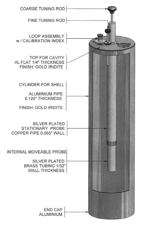
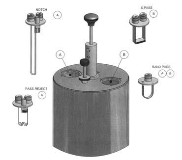
129 FILTERS 128
130 CAVITY FILTER DESIGN Comprod Communications has one of the most rugged, high quality cavity filter constructions in the industry with our field proven, temperature-compensated cavities. The flexibility of four versions of filters, BANDPASS, NOTCH, PASS-REJECT, and X-PASS, available in 2", 4", 6.625", & 10" cavities, allow for any system to be designed for maximum performance and efficiency. All of the following filters can be achieved by only swapping the loops, while maintaining the same cavity, only using 6.625" and 10" cavities. 1. BANDPASS CAVITY FILTER Passes one narrow band of frequencies and attenuates all others with increasing attenuation above and below the pass frequency. The adjustable selectivity characteristics (rotatable loops) to allow a trade-off between insertion loss ( dB) and selectivity. This filter is ideal when the interfering frequencies are not known to any degree of accuracy or when very broadband filtering is needed. 2. NOTCH Passes a relatively wide band of frequencies, while rejecting a very narrow band of frequencies. Notch depth is variable from 15-25dB. Both pass and notch frequencies must be known. The wide passband can be an advantage when filtering multiple channel transmitters and receivers. This filter is ideal for very close separations (70-200KHz) in VHF and ( KHz) in UHF. 3. PASS-REJECT Passes and rejects a relatively narrow band of frequencies. This filter has the greatest notch depth when compared to other types. Notch depth is adjustable, but is referred to a passband insertion loss (0.3dB or 0.6dB typical). Best filter type for moderately close to wide separations (200KHz and greater in VHF and 400KHz and greater in UHF). 4. X-PASS A special type of filter for expandable multicoupler/combiner applications. Characteristics are identical to a bandpass filter, but has a third port for coupling to other channels. This filter is ideal for close frequency spacing with extremely low losses, acts as a hybrid Combiner/Multicoupler, yet is extremely flexible and expandable; 1-21 and over Channel capabilities. All of Comprod Communications 6.625" and 10" filters have two hand movable tuning rods, a coarse and a fine, for a 35% faster tuning capability. Using adjustable silver-plated coupling loops and calibration index label, it easily facilitates setting cavity insertion loss as required for each application. The combination of heavy-gauge aluminum outer conductor, thick heliarc-welded cavity top plates, heavy silver plating on micro finished tuning assemblies, and Invar-based temperature compensation material results in constant performance levels and long-term reliability. Cavity and isolator connectors are Type N Female, with silver-plated brass bodies and gold-plated center contacts. Thru-line cable assemblies are made with high-quality connectors and RG-393B/U Teflon or RG-214/U cable, to provide excellent intermodulation performance at high system power levels. Gold-plated cable connectors center contacts are soldered to the cable, and the dual shield is securely crimped to the connector barrel using pneumatic fixtures and precision dies. All of these attributes contribute to the high quality of products that our clients have become accustomed to. For more information on Comprod Communications X-Pass, Combiners, Multicouplers, Duplexers, Pass Reject, BandPass, or Notch filters, please do not hesitate to contact our Technical Support team at or FILTERS 129

131 FILTER NOMEMCLATURE PP FF XX YY PP Product Category / Product Family 11 Mount Kits 54 X-Pass Conversion Loops 13 Cable Kits/Accessories 55 Variable attenuator 3-15dB 19 X-Racks 56 2nd Harmonic Filter 57 Combline Filter 21 Low Power Single Junction Isolator 58 Pre-Amp 22 Low Power Dual Junction Isolator 59 Pre-Selector 41 High Power Single Junction Isolator 42 High Power Dual Junction Isolator 60 Multicoupler (XMF Version Reject/Pass) 45 RF Loads 61 Band Pass Filter 46 Signal Sampler 62 Pass-Reject Filter 47 Power Divider 63 Notch Filter 48 Hybrid Decouplers VHF/UHF/800/900MHz 64 Band Pass Duplexer Filter 49 Hybrid Coupler (Single Band) 65 Notch Duplexer Filter 66 Pass-Reject Filter 51 Band pass Conversion Loops 67 Notch/Pass Reject BP Duplexer Filter 52 Pass-Reject Conversion Loops 68 X-Pass Filter 53 Notch Conversion Loops 69 Paging Filter FF Frequency Band / Frequency Range XX Cavity Size/# of Channels or Load Size or Termination YY Mounting Style X Product Series XTC Xpandable Transmit Combiner System XTR Xpandable Transmit Receiver System XRM Xpandable Receiver Multicoupler XBC X-Band Coupler (Cross Band Couplers) HTC Hybrid Transmit Combiner FILTERS 130


132 BAND PASS CAVITY MHz CP61-XX-7X Series Comprod Band Pass filters are designed for minimizing interference from adjacent channels and outside systems. They are available in single, dual, triple or more units. Selectivity can be determined by the insertion loss of the cavity or by adding cavity units as needed. Each cavity is temperature compensated for operation between -40ºC to +60º C. Each cavity has a gold alodine finish, silver plated loops, and plated tuning rods. Every cavity is equipped with a coarse and fine tuning rod for quick and easy field or lab re-tuning applications. Temperature Compensation - Assures Frequency Stability High Attenuation - Minimizes desense and interference from adjacent systems Adjustable Loops - Each cavity has a calibration index for easy field tuning Electrical Specifications Frequency Range, MHz Frequency Spacing Min. **** Please Refer To Curves **** Cavity Diameter, in Continuous Power Input Dependant on Insertion Loss, Watts Connectors N Female N Female N Female N Female N Female N Female Insertion Loss **** Please Refer To Curves **** Reject Attenuation **** Please Refer To Curves **** VSWR 1.22:1 1.22:1 1.22:1 1.22:1 1.22:1 1.22:1 Temperature -40ºC to +60ºC -40ºC to +60ºC -40ºC to +60ºC -40ºC to +60ºC -40ºC to +60ºC -40ºC to +60ºC Mechanical Specifications Maximum length, in Weight, lbs n/a n/a Order Information Single Cavity Dual Cavity Triple Cavity 4" Cavity 61-XX XX XX " Cavity 61-XX XX XX-73 10" Cavity 61-XX XX XX FILTERS 131
133 NOTCH CAVITY MHz CP63-XX-7X Series Comprod Notch filters are designed to reject one narrow band of frequencies, while passing all others in the operating band. They provide more isolation by eliminating close adjacent frequencies. The notch cavities can be cascaded or added to one another in order to sharpen the attenuation of the rejection curve. These cavities can be used individually or in multiples. Each cavity is temperature compensated for operation between -40ºC to +60º C. Each cavity has a gold alodine finish, silver plated loops, and plated tuning rods. Every cavity is equipped with a coarse and fine tuning rod for quick and easy field or lab re-tuning applications. Temperature Compensation - Assures Frequency Stability High Attenuation - Minimizes desense and interference Electrical Specifications Frequency Range, MHz Frequency Spacing Min. **** Please Refer To Curves **** Cavity Diameter, in Continuous Power Input Dependant on Insertion Loss, Watts Connectors N Female N Female N Female N Female N Female N Female Insertion Loss **** Please Refer To Curves **** Reject Attenuation **** Please Refer To Curves **** VSWR 1.22:1 1.22:1 1.22:1 1.22:1 1.22:1 1.22:1 Temperature -40ºC to +60ºC -40ºC to +60ºC -40ºC to +60ºC -40ºC to +60ºC -40ºC to +60ºC -40ºC to +60ºC Mechanical Specifications Maximum length, in Weight, lbs n/a n/a Order Information Single Cavity Dual Cavity Triple Cavity 4" Cavity 63-XX XX XX " Cavity 63-XX XX XX-73 10" Cavity 63-XX XX XX-03 FILTERS

134 PASS-REJECT CAVITY MHz CP62-XX-7X Series Comprod Pass Reject filters are designed to pass one frequency and reject another. They provide more attenuation than our standard bandpass type cavities. These Cavities can reject frequencies on either the high or low side of the pass frequency. Each cavity is temperature compensated for operation between -40ºC to +60ºC. Each cavity has a gold alodine finish, silver plated loops, and plated tuning rods. Every cavity is equipped with a coarse and fine tuning rod for quick and easy field or lab re-tuning applications. Temperature Compensation - Assures Frequency Stability High Attenuation - Minimizes desense and interference Electrical Specifications Frequency Range, MHz Frequency Spacing Min. **** Please Refer To Curves **** Cavity Diameter, in Continuous Power Input, Watts Connectors N Female N Female N Female N Female N Female N Female Insertion Loss **** Please Refer To Curves **** Reject Attenuation **** Please Refer To Curves **** VSWR 1.22:1 1.22:1 1.22:1 1.22:1 1.22:1 1.22:1 Temperature -40ºC to +60ºC -40ºC to +60ºC -40ºC to +60ºC -40ºC to +60ºC -40ºC to +60ºC -40ºC to +60ºC Mechanical Specifications Maximum length, in Weight, lbs n/a n/a Order Information Single Cavity Dual Cavity Triple Cavity 4" Cavity 62-XX XX XX " Cavity 62-XX XX XX-73 10" Cavity 62-XX XX XX FILTERS 133
135 XMF MULTICOUPLERS VHF, UHF, & 700/800/900MHz Xpandable BandPass Multicoupler Filters The XMF (Xpandable Bandpass Multicoupler Filter) systems is one of the most unique transmit/receive multicouplers available. Each channel consists of one, two, or three bandpass filters in combination with an exclusive notch filter design, enabling system expansion without modification to existing system channels as long as applicable selectivity standards for minimum channel spacing are met. This new notch filter approach provides a junction between channels, allowing channel frequencies to pass freely to or from the antennas, while diverting all other channel frequencies to the pass-through antenna line terminal and the remaining XMF system channels efficiently and effectively. This characteristic is field tunable over specified bands of operation without any alterations in construction. Channels may be interconnected with any convenient length of cable. There are no length sensitive cables in the path between channel junction cavities. There is also no frequency order of interconnection required. The only requirement is that the minimum spacing for VHF is 0.8MHz and 2MHz at UHF frequencies be observed. The XMF channels are supplied for wall or rack mounting. The individual cavities are mounted with stainless steel strap clamps, and two horizontal mounting bars, in either case, it may be located at a convenient spacing for rack or wall applications. Horizontally spaced mounting holes are standard 19" EIA rack spacing on wall and rack mounts. All of Comprod Communications filters have two hand movable tuning rods, a coarse and a fine, for a 35% faster tuning capability. Using adjustable silver-plated coupling loops and calibration index label, it easily facilitates setting cavity insertion loss as required for each application. The combination of heavy-gauge aluminum outer conductor, thick heliarc-welded cavity top plates, heavy silver plating on micro finished tuning assemblies, and Invar-based temperature compensation material results in a constant performance levels and long-term reliability. Cavity and isolator connectors are Type N Female, with silver-plated brass bodies and gold-plated center contacts. Gold-plated cable connectors center contacts are soldered to the cable, and the dual shield is securely crimped to the connector barrel using pneumatic fixtures and precision dies. All of these attributes contribute to the high quality of products to which our clients have become accustomed to. For more information on Comprod Communications X-Pass, Multicouplers, Duplexers, Pass-Reject, BandPass, or Notch filters, please do not hesitate to contact our Technical Support team at or FILTERS 134


136 BAND PASS MULTICOUPLER VHF MHz CP60-13-XP Series Comprod Band Pass VHF Multicoupler filters are designed for minimizing interference from adjacent channels and outside systems. They are available in single, dual, triple or more units. Selectivity can be determined by the insertion loss of the cavity or by adding cavity units as needed. Each cavity is temperature compensated for operation between -40º C to +60ºC. Each cavity has a gold alodine finish, silver plated loops, and plated tuning rods. Every cavity is equipped with a coarse and fine tuning rod for quick and easy field or lab re-tuning applications. Temperature Compensation - Assures Frequency Stability High Attenuation - Minimizes desense and interference from adjacent systems Adjustable Loops - Each cavity has a calibration index for easy field tuning Electrical Specifications Frequency Range, MHz Frequency Spacing Min., MHz Cavity Diameter, in Continuous Power Input Dependant on Insertion Loss, Watts Connectors N Female N Female N Female Insertion Loss, db 0.7, 1.2, , 2.2, , 3.2 Channel Isolation **** See Curves **** VSWR 1.5:1 1.5:1 1.5:1 Temperature -40ºC to +60ºC -40ºC to +60ºC -40ºC to +60ºC Mechanical Specifications Maximum length, in 34H x 19W x 7D 34H x 19W x 16.5D 34H x 19W x 16.5D Weight, lbs (Kg) 30 (13.6) 36.3 (16.5) 44 (20) FILTERS 135

137 BAND PASS MULTICOUPLER UHF MHz CP60-40-XP Series Comprod Band Pass UHF Multicoupler filters are designed for minimizing interference from adjacent channels and outside systems. They are available in single, dual, triple or more units. Selectivity can be determined by the insertion loss of the cavity or by adding cavity units as needed. Each cavity is temperature compensated for operation between -40ºC to +60ºC. Each cavity has a gold alodine finish, silver plated loops, and plated tuning rods. Every cavity is equipped with a coarse and fine tuning rod for quick and easy field or lab re-tuning applications. Temperature Compensation - Assures Frequency Stability High Attenuation - Minimizes desense and interference from adjacent systems Adjustable Loops - Each cavity has a calibration index for easy field tuning Electrical Specifications Frequency Range, MHz Frequency Spacing Min., MHz Cavity Diameter, in Continuous Power Input Dependant on Insertion Loss, Watts Connectors N Female N Female N Female Insertion Loss, db 0.7, 1.2, , , 3.2 Channel Isolation **** See Curves **** VSWR 1.5:1 1.5:1 1.5:1 Temperature -40ºC to +60ºC -40ºC to +60ºC -40ºC to +60ºC Mechanical Specifications Maximum length, in 16H x 19W x 7D 16H x 19W x 16.5D 16H x 19W x 16.5D Weight, lbs (kg) 18 (8.6) 26 (11.8) 32 (15.2) FILTERS
138 PSEUDO BAND PASS DUPLEXER CP66-FF-74 Comprod Pseudo Band Pass Duplexer filters are designed for quick and easy installations. These filters are designed for combining two frequencies that need extra isolation or used as great pre-selectors. Available in either 4 or 6 cavity configurations if higher levels of isolation are needed. Selectivity can be determined by the field adjustable capacitors. Each cavity is temperature compensated for operation between -40ºC to +60ºC. Each cavity has a gold alodine finish, silver plated loops, and plated tuning rods. Every cavity is equipped with a coarse and fine tuning rod for quick and easy field or lab re-tuning applications. Temperature Compensation - Assures Frequency Stability High Attenuation - Minimizes desense and interference from adjacent systems Adjustable loops - Each cavity has a calibration index for easy field tuning Electrical Specifications Frequency Range, MHz Frequency Spacing Min., MHz Cavity Diameter, in Continuous Power Input, Watts Connectors N Female N Female Insertion Loss, db Channel Min. Separation db VSWR 1.22:1 1.22:1 Temperature -40ºC to +60ºC -40ºC to +60ºC Mechanical Specifications Maximum length, in 34H x 19W x 16.5D 18.5H x 19W x 16.5D Weight, lbs (kg) 44 (20) 32 (15.2) FILTERS 137


139 2-INCH CAVITY DUPLEXERS CP66-FF-2P Series 2" Cavity Duplexers Comprod 2" base station duplexers are ideal for quick and easy installations. These filters are designed for combining two frequencies that need extra isolation or used as great pre-selectors. Available in either 4 or 6 cavity configurations if higher levels of isolation are needed. Selectivity can be determined by the field adjustable capacitors. Each cavity is temperature compensated for operation between -40ºC to +60ºC. Each cavity has a gold alodine finish, silver plated loops, and plated tuning rods. Temperature Compensation - Assures Frequency Stability High Attenuation - Minimizes desense and interference from adjacent systems Electrical Specifications Frequency Range, MHz Frequency Spacing, Min., MHz Cavity Number Cavity Diameter, in Continuous Power Input, Watts Connectors (Equipment/Antenna) BNC/N BNC/N BNC/N BNC/N Insertion Loss, db Channel Isolation, db /90 80/90 VSWR 1.3:1 1.3:1 Temperature -40ºC to +80ºC -40ºC to +80ºC Mechanical Specifications Maximum length, in 5.25H x 19W x 7.25D 5.25H x 19W x 7.25D Mounting 19 Rack Mount These duplexers are available in other frequencies and configurations. Please call our technical support for additional models. FILTERS 138

140 4-INCH CAVITY DUPLEXERS CP66-FF-44 Series (4) 4 Cavity Duplexers These Comprod 4 base station duplexers are ideal for quick and easy installations. These filters are designed for combining two frequencies or used as great pre-selectors. If higher levels of isolation are needed, please take a look at our 6-cavity configurations. Selectivity can be determined by the field adjustable capacitors. Each cavity is temperature compensated for operation between -40º to +60ºC. Each cavity has a gold alodine finish, silver plated loops, and plated tuning rods. Temperature Compensation - Assures Frequency Stability High Attenuation - Minimizes desense and interference from adjacent systems Adjustable loops Electrical Specifications Frequency Range, MHz Frequency Spacing Min. 500KHz 5MHz 9MHz Cavity Diameter (4) - 4 Square (4) - 4 Square (4) - 4 Square Continuous Power Input 350 Watts 350 Watts 150 Watts Connectors N Female N Female N Female Insertion Loss 1.5 db 0.8 db 0.8 db Channel Isolation 70 db 75 db 90 db VSWR 1.22:1 1.22:1 1.22:1 Temperature -40º to +60ºC -40º to +60ºC -40º to +60ºC Mechanical Specifications Maximum Length, in 31H x 19W x 4D 4H x 19W x 16.5D 4H x 19W x 16.5D Weight, lbs (kg) 30 (13.6) 18 (8.2) 16 (7.3) Mounting 19 Rack Mount 19 Rack Mount 19 Rack Mount Order Information Frequency Wall Mount 4 Cavities 6 Cavities 8 Cavities MHz WM MHz WM MHz WM MHz WM MHz WM FILTERS 139

141 4-INCH CAVITY DUPLEXERS CP66-FF-46 Series (6) 4" Cavity Duplexers These Comprod (6) 4" base station duplexers are ideal for quick and easy installations. These filters are designed for combining two frequencies that need extra isolation or used as a great pre-selectors. If higher levels of isolation are needed, please take a look at our 8-cavity configurations. Selectivity can be determined by the field adjustable loops. Each cavity is temperature compensated for operation between -40ºC to +60ºC. Each cavity has a gold alodine finish, silver plated loops, and plated tuning rods. Temperature Compensation - Assures Frequency Stability High Attenuation - Minimizes desense and interference from adjacent systems Electrical Specifications Frequency Range, MHz Frequency Spacing Min., MHz Cavity Diameter (6)- 4" Square (6)- 4" Square (6)- 4" Square Continuous Power Input, Watts Connectors N Female N Female N Female Insertion Loss, db Channel Min. Sep., db VSWR 1.22:1 1.22:1 1.22:1 Temperature -40ºC to +60ºC -40ºC to +60ºC -40ºC to +60ºC Mechanical Specifications Maximum length, in 31H x 19W x 8D 8H x 19W x 16.5D 8H x 19W x 16.5D Weight, lbs (kg) 45 (20.25) 27 (12.15) 24 (10.8) Mounting 19" Rack Mount 19" Rack Mount 19" Rack Mount Order Information Wall Mount 4 Cavities 6 Cavities 8 Cavities WM WM WM FILTERS 140

142 4 CAVITY MOBILE DUPLEXER VHF & UHF 4 Cavity Standard Version The Comprod line of mobile duplexers features compact size, low loss and temperature compensation over the range of -40C to +60C. The use of extruded aluminum cavities and solid shield copper jacketed intercabling assures excellent mechanical and electrical stability. All units are field tuneable by qualified personnel and rated at 50 Watts continuous duty with a maximum VSWR of 1.5 : 1 over the entire tuning range. BNC connectors are standard. Variations on connectors and mountings are available on special order. For N female connectors add suffix N to model number (Ex N) Electrical Specifications Frequency Range, MHz / / / Frequency Separation, MHz Continuous Power Rating, Watts Insertion Loss - db: TX to Antenna Insertion Loss - db: RX to Antenna Isolation - db: TX noise suppression at RX frequency Isolation - db: TX isolation at TX frequency Maximum VSWR, Ohms 1.5:1 1.5 : 1 Impedance, Ohms Connector Type, Female BNC BNC Temperature Range -40ºC to +60ºC -40ºC to +60ºC Mechanical Specifications Height, in (mm) 1-1/4 (31.8) 1-1/4 (31.8) Width, in (mm) 4-1/8 (105) 4-1/8 (105) Depth, in (mm) 7-5/8 (194) 8-3/4 (222) Weight, lbs (kg) 1.5 (0.7) 2 (0.9) Typical Response Curve / 4.5 MHz Spacing Typical Response Curve / 5.0 MHz Spacing FILTERS 141
143 6 CAVITY MOBILE DUPLEXER VHF & UHF 6 Cavity Standard Version The Comprod line of mobile duplexers features compact size, low loss and temperature compensation over the range of -40ºC to +60ºC. The use of extruded aluminum cavities and solid shield copper jacketed intercabling assures excellent mechanical and electrical stability. All units are field tuneable by qualified personnel and rated at 50 Watts continuous duty with a maximum VSWR of 1.5 : 1 over the entire tuning range. BNC connectors are standard. Variations on connectors and mountings are available on special order. For N female connectors add suffix N to model number (Ex N) Electrical Specifications Frequency Range, MHz / / / Frequency Separation, MHz Continuous Power Rating, Watts Insertion Loss - db: TX to Antenna Insertion Loss - db: RX to Antenna Isolation - db: TX noise suppression at RX frequency Isolation - db: TX isolation at TX frequency Maximum VSWR, Ohms 1.5:1 1.5:1 Impedance, Ohms Connector Type, Female BNC BNC Temperature Range -40ºC to +60ºC -40ºC to +60ºC Mechanical Specifications Height, in (mm) 1-1/4 (31.8) 1-1/4 (31.8) Width, in (mm) 6-3/16 (157) 6-3/16 (157) Depth, in (mm) 7-5/8 (222) 8-3/4 (222) Weight, lbs (kg) 2.0 (0.9) 3.5 (1.7) Typical Response Curve / 4.5 MHz Spacing Typical Response Curve / 5.0 MHz Spacing FILTERS 142
144 X-PASS Expandable Multicoupler/Combiner Filters The Next Generation of Filtration The X-Pass system is one of the most innovative filter designs available today. The X-Pass configuration has already been used by the CREST project at Mount Douglas (B.C.), Hydro Quebec, NB DOT, Motorola Systems, and multiple projects in Canada, the U.S.A and internationally. With the properties of a combiner, but the expandability of a multicoupler, our X-Pass filters is one of the most versatile and re-usable filtration systems on the market. The X-Pass transmitter multicoupler/combiner has superior expandability over fixed star junction type configurations. The X-Pass system can be expanded one channel at a time or up to 21 channels with factory-tuned, easy-to-install expansion channel assemblies. Expansion can be completed easily, without modifying the existing system, as easy as adding one or many channels on top of the existing system, (daisy chain). The X-Pass system is a broadband design allowing the system to completely span entire frequency ranges by using the properties of the X-Pass s combiner for close frequency spacing and the X-Pass s multicoupler properties for the normally spaced channels. The X-Pass can span the full MHz, MHz, MHz frequencies with ease. With a 6.625" cavity, Tx-Tx in VHF can be as close to 75KHz in frequency separation or 50KHz using 10" cavities. The X-Pass system has the big advantage of being flexible. With the ability to combine Bandpass, Pass-Reject, or Notch 6.625" & 10" cavity filters within the X-Pass configuration, once difficult duplex operating requirements can be easily resolved with any customized design. This allows the X-Pass system to have unlimited combinations that can be integrated using multi-cavity configurations, while retaining the expandability of the X-Pass combiner properties for close frequency spaced channels using 6.625" and 10" cavities.your system can now be a hybrid, part combiner for close frequency spaced channels while encompassing the expandability of part standard multicouplers that can be integrated with standard Bandpass, Notch, and Pass-Reject filter combinations. All X-Pass systems are fully assembled, ready for Bolt, Plug, and then Play installations. The X-Pass system has one more beneficial aspect, the optional X-Pass Rack. With this ingenious rack design, some systems can take up to 50% less space than normal systems in a 19-inch rack. Even our Stak Rack cannot compete with the efficiencies of the X-Pass Rack. By being able to mount all cavities horizontally, the ability to expand one channel on top of another in no particular order, and not having the physical obstacles of mounting a star-junction type configuration in a rack, the X-Pass system can save valuable installation space, that in most cases, is a premium, especially for future expansion projects. For more information on Comprod Communications X-Pass, Multicouplers, Duplexers, Pass-Reject, BandPass, or Notch filters, please do not hesitate to contact our Technical Support team at or FILTERS 143

145 X-PASS CAVITY MHz CP68-XX-7X Series Comprod X-Pass filters are designed for flexible, close frequency systems. Each cavity contains both a Reject and Pass Band curve. These individual cavities are used to add channels to already existing systems. They are only available in single units, but can be combined with Band Pass, Notch, and Pass Reject cavities for added protection and isolation. Selectivity can be determined by the insertion loss of the cavity or by adding Band Pass cavity units after this Expansion channel as needed. Each cavity is temperature compensated for operation between -40ºC to +60ºC. Each cavity has a gold alodine finish, silver plated loops, and plated tuning rods. Every cavity is equipped with a coarse and fine tuning rod for quick and easy field or lab re-tuning applications. Temperature Compensation - Assures Frequency Stability High Attenuation - Minimizes desense and interference from adjacent systems Adjustable Loops - Each cavity has a calibration index for easy field tuning Electrical Specifications Frequency Range, MHz Frequency Spacing Min. **** Please Refer To Curves **** Cavity Diameter, in Continuous Power Input, Watts Connectors N Female N Female N Female N Female N Female N Female Insertion Loss **** Please Refer To Curves **** Reject Attenuation **** Please Refer To Curves **** VSWR 1.22:1 1.22:1 1.22:1 1.22:1 1.22:1 1.22:1 Temperature -40ºC to +60ºC -40ºC to +60ºC -40ºC to +60ºC -40ºC to +60ºC -40ºC to +60ºC -40ºC to +60ºC Mechanical Specifications Maximum length, in Weight, lbs n/a n/a Order Information Single Cavity 4" Cavity 68-XX " Cavity 68-XX-71 10" Cavity 68-XX-01 FILTERS
146 XPANDABLE TRANSMIT COMBINER 66-88MHz XTC Xpandable Transmit Combiner Series 7" Cavity The XTC is the newest evolution of our X-Pass technology. Our Xpandable Transmit Combiners can combine 1 to 21 channels. The XTC series of filters incorporates expandability, close frequency spacing and some of the lowest insertion losses in the industry. Using a 6.625" cavity, the XTC can easily support 50KHz Tx-Tx spacing or 50KHz spacing while using 10" cavities. Each cavity is constructed using a gold alodine finish, silver plated loops, silver plated connectors and internal tuning plunger. Additionally, cavities are temperature compensated for operation between -40ºC to +60ºC. Every cavity is equipped with a coarse and fine tuning rod for quick and easy field or lab re-tuning. Flexible & Expandable Design Channels Capacity Expandable 1 or more Channels at a time - Re-Configurable Equipment MHz, 22MHz of Operating Bandwidth Temperature Compensation - Assures Frequency Stability High Attenuation - Minimizes desense and interference Ultra-Low Insertion Losses - Low coupling Losses - Low bridging Losses Continuous High Power Handling Capability Watts 24/7 Electrical Specifications XTC XTC XTC XTC XTC XTC Frequency Range, MHz Bandwidth, MHz Number of Channels Cavity Diameter, in Min. Channel Sep., KHz Isolation Min. Tx-Tx, db Isolation Min. Ant-Tx, db Max. Insertion Loss Per Chan., db Continuous Power Input, Watts Connectors N Female N Female N Female N Female N Female N Female VSWR 1.22:1 1.22:1 1.22:1 1.22:1 1.22:1 1.22:1 Temperature -40Cº to +60ºC -40ºC to +60ºC -40ºC to +60ºC -40ºC to +60ºC -40ºC to +60ºC -40ºC to +60ºC Mechanical Specifications Height, in (mm) - (Mounted in X Rack) 65.25H x 24W x 40.25D (1659 x 610 x 1022) Mounts in 19" Standard Rack Yes Yes Yes Yes Yes Yes Weight **** DEPENDS ON SET-UP AND RACK DESIGN **** Order Information Single Cavity 2 - Channel 3 - Channel 5 - Channel 8 - Channel 4" Cavity XTC XTC XTC XTC XTC " Cavity XTC XTC XTC XTC XTC " Cavity XTC XTC XTC XTC XTC FILTERS 145
147 XPANDABLE TRANSMIT COMBINER 66-88MHz XTC Xpandable Transmit Combiner Series 10" Cavity The XTC is the newest evolution of our X-Pass technology. Our Xpandable Transmit Combiners can combine 1 to 21 channels. The XTC series of filters incorporates expandability, close frequency spacing and some of the lowest insertion losses in the industry. Using a 6.625" cavity, the XTC can easily support 50KHz Tx-Tx spacing or 50KHz spacing while using 10" cavities. Each cavity is constructed using a gold alodine finish, silver plated loops, silver plated connectors and internal tuning plunger. Additionally, cavities are temperature compensated for operation between -40ºC to +60ºC. Every cavity is equipped with a coarse and fine tuning rod for quick and easy field or lab re-tuning. Flexible & Expandable Design Channels Capacity - Expandable 1 or more Channels at a time - Re-Configurable Equipment MHz, 22MHz of Operating Bandwidth Temperature Compensation - Assures Frequency Stability - Minimizes desense and interference Ultra-Low Insertion Losses - Low coupling Losses - Low bridging Losses Continuous High Power Handling Capability Watts 24/7 Electrical Specifications XTC XTC XTC XTC XTC Frequency Range, MHz Bandwidth, MHz Number of Channels Cavity Diameter, in Min. Channel Sep., KHz Isolation Min. Tx-Tx, db Isolation Min. Ant-Tx, db Max. Insertion Loss Per Chan., db Continuous Power Input, Watts Connectors N Female N Female N Female N Female N Female VSWR 1.22:1 1.22:1 1.22:1 1.22:1 1.22:1 Temperature -40ºC to +60ºC -40ºC to +60ºC -40ºC to +60ºC -40ºC to +60ºC -40ºC to +60ºC Mechanical Specifications Height, in (mm) - (Mounted in X Rack) 65.25H x 24W x 40.25D (1659 x 610 x 1022) Mounts in 19" Standard Rack Yes Yes Yes Yes Yes Weight **** DEPENDS ON SET-UP AND RACK DESIGN **** FILTERS Order Information Single Channel 2 - Channel 3 - Channel 5 - Channel 8 - Channel 4" Cavity XTC XTC XTC XTC XTC " Cavity XTC XTC XTC XTC XTC " Cavity XTC XTC XTC XTC XTC
148 XPANDABLE TRANSMIT COMBINER MHz XTC Xpandable Transmit Combiner Series 7" Cavity The XTC is the newest evolution of our X-Pass technology. Our Xpandable Transmit Combiners can combine 1 to 21 channels. The XTC series of filters incorporates expandability, close frequency spacing and some of the lowest insertion losses in the industry. Using a 6.625" cavity, the XTC can easily support 75KHz Tx-Tx spacing or 50KHz spacing while using 10" cavities. Each cavity is constructed using a gold alodine finish, silver plated loops, silver plated connectors and internal tuning plunger. Additionally, cavities are temperature compensated for operation between -40ºC to +60ºC. Every cavity is equipped with a coarse and fine tuning rod for quick and easy field or lab re-tuning. Flexible & Expandable Design Channels Capacity - Expandable 1 or more Channels at a time - Re-Configurable Equipment MHz, 28MHz of Operating Bandwidth Temperature Compensation - Assures Frequency Stability High Attenuation - Minimizes Decense and interference Ultra-Low Insertion Losses - Low coupling Losses - Low bridging Losses Continuous High Power Handling Capability Watts 24/7 Electrical Specifications XTC XTC XTC XTC XTC XTC Frequency Range, MHz Bandwidth, MHz Number of Channels Cavity Diameter, in Min. Channel Sep., KHz Isolation Min. Tx-Tx, db Isolation Min. Ant-Tx, db Max. Insertion Loss Per Chan., db Continuous Power Input, Watts Connectors N Female N Female N Female N Female N Female N Female VSWR 1.22:1 1.22:1 1.22:1 1.22:1 1.22:1 1.22:1 Temperature -40ºC to +60ºC -40ºC to +60ºC -40ºC to +60ºC -40ºC to +60ºC -40ºC to +60ºC -40ºC to +60ºC Mechanical Specifications Height, in (mm) - (Mounted in X Rack) 65.25H x 24W x 40.25D (1659 x 610 x 1022) Mounts in 19" Standard Rack Yes Yes Yes Yes Yes Yes Weight **** DEPENDS ON SET-UP AND RACK DESIGN **** Order Information Single Channel 2 - Channel 3 - Channel 5 - Channel 8 - Channel 4" Cavity XTC XTC XTC XTC XTC " Cavity XTC XTC XTC XTC XTC " Cavity XTC XTC XTC XTC XTC FILTERS 147
149 XPANDABLE TRANSMIT COMBINER MHz XTC Xpandable Transmit Combiner Series 10" Cavity The XTC is the newest evolution of our X-Pass technology. Our Xpandable Transmit Combiners can combine 1 to 21 channels. The XTC series of filters incorporates expandability, close frequency spacing and some of the lowest insertion losses in the industry. Using a 6.625" cavity, the XTC can easily support 75KHz Tx-Tx spacing or 50KHz spacing while using 10" cavities. Each cavity is constructed using a gold alodine finish, silver plated loops, silver plated connectors and internal tuning plunger. Additionally, cavities are temperature compensated for operation between -40ºC to +60ºC. Every cavity is equipped with a coarse and fine tuning rod for quick and easy field or lab re-tuning. Flexible & Expandable Design Channels Capacity - Expandable 1 or more Channels at a time - Re-Configurable Equipment MHz, 28MHz of Operating Bandwidth Temperature Compensation - Assures Frequency Stability High Attenuation - Minimizes desense and interference Ultra-Low Insertion Losses - Low coupling Losses - Low bridging Losses Continuous High Power Handling Capability Watts 24/7 Electrical Specifications XTC XTC XTC XTC XTC XTC Frequency Range, MHz Bandwidth, MHz Number of Channels Cavity Diameter, in Min. Channel Sep., KHz Isolation Min. Tx-Tx, db Isolation Min. Ant-Tx, db Max. Insertion Loss Per Chan., db Continuous Power Input, Watts Connectors N Female N Female N Female N Female N Female N Female VSWR 1.22:1 1.22:1 1.22:1 1.22:1 1.22:1 1.22:1 Temperature -40ºC to +60ºC -40ºC to +60ºC -40ºC to +60ºC -40ºC to +60ºC -40ºC to +60ºC -40ºC to +60ºC Mechanical Specifications Height, in (mm) - (Mounted in X Rack) 65.25H x 24W x 40.25D (1659 x 610 x 1022) Mounts in 19" Standard Rack Yes Yes Yes Yes Yes Yes Weight **** DEPENDS ON SET-UP AND RACK DESIGN **** FILTERS Order Information Single Channel 2 - Channel 3 - Channel 5 - Channel 8 - Channel 4" Cavity XTC XTC XTC XTC XTC " Cavity XTC XTC XTC XTC XTC " Cavity XTC XTC XTC XTC XTC
150 XPANDABLE TRANSMIT COMBINER MHz XTC Xpandable Transmit Combiner Series 7" Cavity The XTC is the newest evolution of our X-Pass technology. Our Xpandable Transmit Combiners can combine 1 to 21 channels. The XTC series of filters incorporates expandability, close frequency spacing and some of the lowest insertion losses in the industry. Using a 6.625" cavity, the XTC can easily support 75KHz Tx-Tx spacing or 50KHz spacing while using 10" cavities. Each cavity is constructed using a gold alodine finish, silver plated loops, silver plated connectors and internal tuning plunger. Additionally, cavities are temperature compensated for operation between -40ºC to +60ºC. Every cavity is equipped with a coarse and fine tuning rod for quick and easy field or lab re-tuning. Flexible & Expandable Design Channels Capacity - Expandable 1 or more Channels at a time - Re-Configurable Equipment MHz, 42MHz of Operating Bandwidth Temperature Compensation - Assures Frequency Stability High Attenuation - Minimizes Decense and interference Ultra-Low Insertion Losses - Low coupling Losses - Low bridging Losses Continuous High Power Handling Capability Watts 24/7 Electrical Specifications XTC XTC XTC XTC XTC XTC Frequency Range, MHz Bandwidth, MHz Number of Channels Cavity Diameter, in Min. Channel Sep., KHz Isolation Min. Tx-Tx, db Isolation Min. Ant-Tx, db Max. Insertion Loss Per Chan., db Continuous Power Input, Watts Connectors N Female N Female N Female N Female N Female N Female VSWR 1.22:1 1.22:1 1.22:1 1.22:1 1.22:1 1.22:1 Temperature -40ºC to +60ºC -40ºC to +60ºC -40ºC to +60ºC -40ºC to +60ºC -40ºC to +60ºC -40ºC to +60ºC Mechanical Specifications Height, in (mm) - (Mounted in X Rack) 65.25H x 24W x 40.25D (1659 x 610 x 1022) Mounts in 19" Standard Rack Yes Yes Yes Yes Yes Yes Weight **** DEPENDS ON SET-UP AND RACK DESIGN **** Order Information Single Channel 2 - Channel 3 - Channel 5 - Channel 8 - Channel 4" Cavity XTC XTC XTC XTC XTC " Cavity XTC XTC XTC XTC XTC " Cavity XTC XTC XTC XTC XTC FILTERS 149
151 XPANDABLE TRANSMIT COMBINER MHz XTC Xpandable Transmit Combiner Series 10" Cavity The XTC is the newest evolution of our X-Pass technology. Our Xpandable Transmit Combiners can combine 1 to 21 channels. The XTC series of filters incorporates expandability, close frequency spacing and some of the lowest insertion losses in the industry. Using a 6.625" cavity, the XTC can easily support 75KHz Tx-Tx spacing or 50KHz spacing while using 10" cavities. Each cavity is constructed using a gold alodine finish, silver plated loops, silver plated connectors and internal tuning plunger. Additionally, cavities are temperature compensated for operation between -40ºC to +60ºC. Every cavity is equipped with a coarse and fine tuning rod for quick and easy field or lab re-tuning. Flexible & Expandable Design Channels Capacity - Expandable 1 or more Channels at a time - Re-Configurable Equipment MHz, 42MHz of Operating Bandwidth Temperature Compensation - Assures Frequency Stability High Attenuation - Minimizes desense and interference Ultra-Low Insertion Losses - Low coupling Losses - Low bridging Losses Continuous High Power Handling Capability Watts 24/7 Electrical Specifications XTC XTC XTC XTC XTC XTC Frequency Range, MHz Bandwidth, MHz Number of Channels Cavity Diameter, in Min. Channel Sep., KHz Isolation Min. Tx-Tx, db Isolation Min. Ant-Tx, db Max. Insertion Loss Per Chan., db Continuous Power Input, Watts Connectors N Female N Female N Female N Female N Female N Female VSWR 1.22:1 1.22:1 1.22:1 1.22:1 1.22:1 1.22:1 Temperature -40ºC to +60ºC -40ºC to +60ºC -40ºC to +60ºC -40ºC to +60ºC -40ºC to +60ºC -40ºC to +60ºC Mechanical Specifications Height, in (mm) - (Mounted in X Rack) 65.25H x 24W x 40.25D (1659 x 610 x 1022) Mounts in 19" Standard Rack Yes Yes Yes Yes Yes Yes Weight **** DEPENDS ON SET-UP AND RACK DESIGN **** FILTERS Order Information Single Cavity 2 - Channel 3 - Channel 5 - Channel 8 - Channel 4" Cavity XTC XTC XTC XTC XTC " Cavity XTC XTC XTC XTC XTC " Cavity XTC XTC XTC XTC XTC
152 XPANDABLE TRANSMIT COMBINER MHz XTC Xpandable Transmit Combiner Series 7" Cavity The XTC is the newest evolution of our X-Pass technology. Our Xpandable Transmit Combiners can combine 1 to 21 channels. The XTC series of filters incorporates expandability, close frequency spacing and some of the lowest insertion losses in the industry. Using a 6.625" cavity, the XTC can easily support 100KHz Tx-Tx spacing or 75KHz spacing while using 10" cavities. Each cavity is constructed using a gold alodine finish, silver plated loops, silver plated connectors and internal tuning plunger. Additionally, cavities are temperature compensated for operation between -40ºC to +60ºC. Every cavity is equipped with a coarse and fine tuning rod for quick and easy field or lab re-tuning. Flexible & Expandable Design Channels Capacity - Expandable 1 or more Channels at a time - Re-Configurable Equipment MHz, 85MHz of Operating Bandwidth Temperature Compensation - Assures Frequency Stability High Attenuation - Minimizes desense and interference Ultra-Low Insertion Losses - Low coupling Losses - Low bridging Losses Continuous High Power Handling Capability Watts 24/7 Electrical Specifications XTC XTC XTC XTC XTC XTC Frequency Range, MHz Bandwidth, MHz Number of Channels Cavity Diameter, in Min. Channel Sep., KHz Isolation Min. Tx-Tx, db Isolation Min. Ant-Tx, db Max. Insertion Loss Per Chan., db Continuous Power Input, Watts Connectors N Female N Female N Female N Female N Female N Female VSWR 1.22:1 1.22:1 1.22:1 1.22:1 1.22:1 1.22:1 Temperature -40ºC to +60ºC -40ºC to +60ºC -40ºC to +60ºC -40ºC to +60ºC -40ºC to +60ºC -40ºC to +60ºC Mechanical Specifications Height, in (mm) - (Mounted in X Rack) 65.25H x 24W x 26.4D (1659 x 610 x 671) Mounts in 19" Standard Rack Yes Yes Yes Yes Yes Yes Weight **** DEPENDS ON SET-UP AND RACK SIZE **** Order Information Single Channel 2 - Channel 3 - Channel 5 - Channel 8 - Channel 4" Cavity XTC XTC XTC XTC XTC " Cavity XTC XTC XTC XTC XTC " Cavity XTC XTC XTC XTC XTC FILTERS 151
153 XPANDABLE TRANSMIT COMBINER MHz XTC Xpandable Transmit Combiner Series 10" Cavity The XTC is the newest evolution of our X-Pass technology. Our Xpandable Transmit Combiners can combine 1 to 21 channels. The XTC series of filters incorporates expandability, close frequency spacing and some of the lowest insertion losses in the industry. Using a 6.625" cavity, the XTC can easily support 125KHz Tx-Tx spacing or 75KHz spacing while using 10" cavities. Each cavity is constructed using a gold alodine finish, silver plated loops, silver plated connectors and internal tuning plunger. Additionally, cavities are temperature compensated for operation between -40ºC to +60ºC. Every cavity is equipped with a coarse and fine tuning rod for quick and easy field or lab re-tuning. Flexible & Expandable Design Channels Capacity - Expandable 1 or more Channels at a time - Re-Configurable Equipment MHz, 85MHz of Operating Bandwidth Temperature Compensation - Assures Frequency Stability High Attenuation - Minimizes desense and interference Ultra-Low Insertion Losses - Low coupling Losses - Low bridging Losses Continuous High Power Handling Capability Watts 24/7 Electrical Specifications XTC XTC XTC XTC XTC XTC Frequency Range, MHz Bandwidth, MHz Number of Channels Cavity Diameter, in Min. Channel Sep., KHz Isolation Min. Tx-Tx, db Isolation Min. Ant-Tx, db Max. Insertion Loss Per Chan., db Continuous Power Input, Watts Connectors N Female N Female N Female N Female N Female N Female VSWR 1.22:1 1.22:1 1.22:1 1.22:1 1.22:1 1.22:1 Temperature -40ºC to +60ºC -40ºC to +60ºC -40ºC to +60ºC -40ºC to +60ºC -40ºC to +60ºC -40ºC to +60ºC Mechanical Specifications Height, in (mm) - (Mounted in X Rack) 79.5H x 24W x 28.4D (2019 x 610 x 721) Mounts in 19" Standard Rack Yes Yes Yes Yes Yes Yes Weight **** DEPENDS ON SET-UP AND RACK DESIGN **** FILTERS Order Information Single Channel 2 - Channel 3 - Channel 5 - Channel 8 - Channel 4" Cavity XTC XTC XTC XTC XTC " Cavity XTC XTC XTC XTC XTC " Cavity XTC XTC XTC XTC XTC
154 XPANDABLE TRANSMIT COMBINER MHz XTC Xpandable Transmit Combiner Series 7" Cavity The XTC is the newest evolution of our X-Pass technology. Our Xpandable Transmit Combiners can combine 1 to 21 channels. The XTC series of filters incorporates expandability, close frequency spacing and some of the lowest insertion losses in the industry. Using a 6.625" cavity, the XTC can easily support 125KHz Tx-Tx spacing or 75KHz spacing while using 10" cavities. Each cavity is constructed using a gold alodine finish, silver plated loops, silver plated connectors and internal tuning plunger. Additionally, cavities are temperature compensated for operation between -40ºC to +60ºC. Every cavity is equipped with a coarse and fine tuning rod for quick and easy field or lab re-tuning. Flexible & Expandable Design Channels Capacity - Expandable 1 or more Channels at a time - Re-Configurable Equipment MHz, 132MHz of Operating Bandwidth Temperature Compensation - Assures Frequency Stability High Attenuation - Minimizes desense and interference Ultra-Low Insertion Losses - Low coupling Losses - Low bridging Losses Continuous High Power Handling Capability Watts 24/7 Electrical Specifications XTC XTC XTC XTC XTC XTC Frequency Range, MHz Bandwidth, MHz Number of Channels Cavity Diameter, in Min. Channel Sep., KHz Isolation Min. Tx-Tx, db Isolation Min. Ant-Tx, db Max. Insertion Loss Per Chan., db Continuous Power Input, Watts Connectors N Female N Female N Female N Female N Female N Female VSWR 1.22:1 1.22:1 1.22:1 1.22:1 1.22:1 1.22:1 Temperature -40ºC to +60ºC -40ºC to +60ºC -40ºC to +60ºC -40ºC to +60ºC -40ºC to +60ºC -40ºC to +60ºC Mechanical Specifications Height, in (mm) - (Mounted in X Rack)* 65.25H x 24W x 36D (1659 x 610 x 914) Mounts in 19" Standard Rack Yes Yes Yes Yes Yes Yes Weight **** DEPENDS ON SET-UP AND RACK DESIGN **** *Using 3/4 wave cavity configuration (available in 1/4 wave configuration). Order Information Single Channel 2 - Channel 3 - Channel 5 - Channel 8 - Channel 4" Cavity XTC XTC XTC XTC XTC " Cavity XTC XTC XTC XTC XTC " Cavity XTC XTC XTC XTC XTC FILTERS 153

155 XPANDABLE TRANSMIT COMBINER MHz XTC Xpandable Transmit Combiner Series 10" Cavity The XTC is the newest evolution of our X-Pass technology. Our Xpandable Transmit Combiners can combine 1 to 21 channels. The XTC series of filters incorporates expandability, close frequency spacing and some of the lowest insertion losses in the industry. Using a 6.625" cavity, the XTC can easily support 125KHz Tx-Tx spacing or 75KHz spacing while using 10" cavities. Each cavity is constructed using a gold alodine finish, silver plated loops, silver plated connectors and internal tuning plunger. Additionally, cavities are temperature compensated for operation between -40ºC to +60ºC. Every cavity is equipped with a coarse and fine tuning rod for quick and easy field or lab re-tuning. Flexible & Expandable Design Channels Capacity - Expandable 1 or more Channels at a time - Re-Configurable Equipment MHz, 132MHz of Operating Bandwidth Temperature Compensation - Assures Frequency Stability High Attenuation - Minimizes desense and interference Ultra-Low Insertion Losses - Low coupling Losses - Low bridging Losses Continuous High Power Handling Capability Watts 24/7 Electrical Specifications XTC XTC XTC XTC XTC XTC Frequency Range, MHz Bandwidth, MHz Number of Channels Cavity Diameter, in Min. Channel Sep., KHz Isolation Min. Tx-Tx, db Isolation Min. Ant-Tx, db Max. Insertion Loss Per Chan., db Continuous Power Input, Watts Connectors N Female N Female N Female N Female N Female N Female VSWR 1.22:1 1.22:1 1.22:1 1.22:1 1.22:1 1.22:1 Temperature -40ºC to +60ºC -40ºC to +60ºC -40ºC to +60ºC -40ºC to +60ºC -40ºC to +60ºC -40ºC to +60ºC Mechanical Specifications Height, in (mm) - (Mounted in X Rack) 79.5H x 24W x 36D (2019 x 610 x 914) Mounts in 19" Standard Rack Yes Yes Yes Yes Yes Yes Weight **** DEPENDS ON SET-UP AND RACK DESIGN **** FILTERS Order Information Single Channel 2 - Channel 3 - Channel 5 - Channel 8 - Channel 4" Cavity XTC XTC XTC XTC XTC " Cavity XTC XTC XTC XTC XTC " Cavity XTC XTC XTC XTC XTC

156 XPANDABLE TRANSMIT COMBINER MHz XTC Xpandable Transmit Combiner Series 7" Cavity The XTC is the newest evolution of our X-Pass technology. Our Xpandable Transmit Combiners can combine 1 to 21 channels. The XTC series of filters incorporates expandability, close frequency spacing and some of the lowest insertion losses in the industry. Using a 6.625" cavity, the XTC can easily support 250KHz Tx-Tx spacing. Each cavity is constructed using a gold alodine finish, silver plated loops, silver plated connectors and internal tuning plunger. Additionally, cavities are temperature compensated for operation between -40ºC to +60ºC. Every cavity is equipped with a coarse and fine tuning rod for quick and easy field or lab re-tuning. Flexible & Expandable Design Channels Capacity - Expandable 1 or more Channels at a time - Re-Configurable Equipment MHz, 254MHz of Operating Bandwidth Temperature Compensation - Assures Frequency Stability High Attenuation - Minimizes desense and interference Ultra-Low Insertion Losses - Low coupling Losses - Low bridging Losses Continuous High Power Handling Capability Watts 24/7 Electrical Specifications XTC XTC XTC XTC XTC XTC Frequency Range, MHz Bandwidth, MHz Number of Channels Cavity Diameter, in Min. Channel Sep., KHz Isolation Min. Tx-Tx, db Isolation Min. Ant-Tx, db Max. Insertion Loss Per Chan Continuous Power Input Connectors N Female N Female N Female N Female N Female N Female VSWR 1.22:1 1.22:1 1.22:1 1.22:1 1.22:1 1.22:1 Temperature -40ºC to +60ºC -40ºC to +60ºC -40ºC to +60ºC -40ºC to +60ºC -40ºC to +60ºC -40ºC to +60ºC Mechanical Specifications Height, in (Mounted in X Rack) 65.25H x 24W x 20.7D (1659 x 610 x 526) Mounts in 19" Standard Rack Yes Yes Yes Yes Yes Yes Weight **** DEPENDS ON SET-UP AND RACK DESIGN **** Order Information Single Channel 2 - Channel 3 - Channel 5 - Channel 8 - Channel 4" Cavity XTC XTC XTC XTC XTC " Cavity XTC XTC XTC XTC XTC " Cavity XTC XTC XTC XTC XTC FILTERS 155
157 XTR XPANDABLE TRANSMIT RECEIVER The Next Generation of Combiners Our X-Pass technology has been taken to the next level. We can now combine your Tx & Rx frequencies onto the same antenna. Our System Design Department can integrate any type of frequency, even in close frequency spaced systems, allowing you to minimize the systems physical space, maximize the efficiency of your system, and combine your Txs and Rxs onto one antenna. Each of our system designs comes with a full intermodulation study that examines all of the Intermod hits that you would have in your system and even within the tower. Once we have fully examined your intermodulation study, we proceed with a fully customized system solution specific to your needs. There are no box solutions packaged for your needs, all of our solutions are custom tailored to your exact applications requirements. Call now for your free customized system. Tx and Rx frequencies will be needed. Here are some examples: Filter 1 Filter 3 Filter 4 FILTERS Filter 2 156
158 Filter 5 Filter 6 Filter 7 FILTERS 157
159 RECEIVER MULTICOUPLER MHz CP XRM-FF-PP Series Comprod Xpandable Receiver Multicouplers are simple and compact. They are available in 2, 4, 8, 12, and 16 port configurations. This is an affordable means of combining multiple Rx frequencies onto the same antenna. We offer three mounting versions: our standard 19" rack, a tray-mounted and a cavity-mounted version. Each unit consists of a power splitter and an RF amplifier. Every Xpandable Receiver multicouplers has the available optional plug-in power supply. Design - Simple and Cost Effective Mounting - 19" Rack Mount (RM) - Cavity Mount (CM) - Tray Mount (TRM) Optional Power Supply (PS) Electrical Specifications XRM XRM XRM XRM Frequency Range, MHz Pass Band, MHz # of Channels Rx/Rx Isolation, db System Voltage, VDC Amplifier Gain, db Amplifier Noise Figure, db Amplifier Bias Voltage, VDC Amplifier Current Draw, ma Nominal Impedance, Ohms Max. VSWR 1.25:1 1.25:1 1.25:1 1.25:1 Temperature -40ºC to +60ºC -40ºC to +60ºC -40ºC to +60ºC -40ºC to +60ºC Mechanical Specifications Mounting RM / CM RM / CM RM / CM RM / CM Connectors BNC / N BNC / N BNC / N BNC / N Weight, lbs Order Information Rack Mount Cavity Mount Tray Mount Power Supply XRM XRM-13-02RM XRM-13-02CM XRM-13-02TRM XRM-13-02PS XRM XRM-13-04RM XRM-13-04CM XRM-13-04TRM XRM-13-04PS XRM XRM-13-08RM XRM-13-08CM XRM-13-08TRM XRM-13-08PS XRM XRM-13-16RM XRM-13-16CM XRM-13-16TRM XRM-13-16PS FILTERS 158
160 RECEIVER MULTICOUPLER MHz CP XRM-FF-PP Series Comprod Xpandable Receiver Multicouplers are simple and compact. They are available in 2, 4, 8, 12, and 16 port configurations. This is an affordable means of combining multiple Rx frequencies onto the same antenna. We offer three mounting versions: our standard 19" rack, tray mounted and a cavity mounted version. Each unit consists of a power splitter and an RF amplifier. Every Xpandable Receiver Multicouplers has the available optional plug-in power supply. Design - Simple and Cost Effective Mounting - 19" Rack Mount (RM) - Cavity Mount (CM) - Tray Mount (TRM) Optional Power Supply (PS) Electrical Specifications XRM XRM XRM XRM Frequency Range, MHz Pass Band, MHz # of Channels Rx/Rx Isolation, db System Voltage, VDC Amplifier Gain, db Amplifier Noise Figure, db Amplifier Bias Voltage, VDC Amplifier Current Draw, ma Nominal Impedance, Ohms Max. VSWR 1.25:1 1.25:1 1.25:1 1.25:1 Temperature -40ºC to +60ºC -40ºC to +60ºC -40ºC to +60ºC -40ºC to +60ºC Mechanical Specifications Mounting RM / CM RM / CM RM / CM RM / CM Connectors (Input / Output) BNC / N BNC / N BNC / N BNC / N Weight, lbs Order Information Rack Mount Cavity Mount Tray Mount Power Supply XRM XRM-30-02RM XRM-30-02CM XRM-30-02TRM XRM-30-02PS XRM XRM-30-04RM XRM-30-04CM XRM-30-04TRM XRM-30-04PS XRM XRM-30-08RM XRM-30-08CM XRM-30-08TRM XRM-30-08PS XRM XRM-30-16RM XRM-30-16CM XRM-30-16TRM XRM-30-16PS FILTERS 159
161 RECEIVER MULTICOUPLER MHz CP XRM-FF-PP Series Comprod Xpandable Receiver Multicouplers are simple and compact.they are available in 2, 4, 8, 12, and 16 port configurations. This is an affordable means of combining multiple Rx frequencies onto the same antenna. We offer three mounting versions: our standard 19" rack, tray mounted and a cavity mounted version. Each unit consists of a power splitter and an RF amplifier. Every Xpandable Receiver multicouplers has the offered optional plug-in power supply. Design - Simple and Cost Effective Mounting - 19" Rack Mount( RM) - Cavity Mount (CM) - Tray Mount (TM) Optional Power Supply (PS) Electrical Specifications XRM XRM XRM XRM XRM Frequency Range, MHz Pass Band, MHz # of Channels Rx/Rx Isolation, db System Voltage, VDC Amplifier Gain, db Amplifier Noise Figure, db Amplifier Bias Voltage, VDC Amplifier Current Draw, ma Nominal Impedance, Ohms Max. VSWR 1.25:1 1.25:1 1.25:1 1.25:1 1.25:1 Temperature -40ºC to +60ºC -40ºC to +60ºC -40ºC to +60ºC -40ºC to +60ºC -40ºC to +60ºC Mechanical Specifications Mounting RM / CM RM / CM RM / CM RM / CM RM / CM Connectors BNC / N BNC / N BNC / N BNC / N BNC / N Weight, lbs Order Information Rack Mount Cavity Mount Tray Mount Power Supply XRM XRM-80-02RM XRM-80-02CM XRM-80-02TRM XRM-80-02PS XRM XRM-80-04RM XRM-80-04CM XRM-80-04TRM XRM-80-04PS XRM XRM-80-08RM XRM-80-08CM XRM-80-08TRM XRM-80-08PS XRM XRM-80-16RM XRM-80-16CM XRM-80-16TRM XRM-80-16PS FILTERS 160

 - Cavity Mount (CM) - Tray Mount (TRM) Optional Power Supply (PS) Electrical Specifications XRM-90-02 XRM-90-04 XRM-90-08 XRM-90-16")
162 RECEIVER MULTICOUPLER MHz CP XRM-FF-PP Series Comprod Xpandable Receiver Multicouplers are simple and compact. They are available in 2, 4, 8, 12, and 16 port configurations. This is an affordable means of combining multiple Rx frequencies onto the same antenna. We offer three mounting versions: our standard 19" rack, tray mounted and a cavity mounted version. Each unit consists of a power splitter and an RF amplifier. Every Xpandable Receiver multicouplers has the offered optional plug-in power supply. Design - Simple and Cost Effective Mounting - 19" Rack Mount (RM) - Cavity Mount (CM) - Tray Mount (TRM) Optional Power Supply (PS) Electrical Specifications XRM XRM XRM XRM XRM Frequency Range, MHz Pass Band, MHz # of Channels Rx/Rx Isolation, db System Voltage, VDC Amplifier Gain, db Amplifier Noise Figure, db Amplifier Bias Voltage, VDC Amplifier Current Draw, ma Nominal Impedance, Ohms Max. VSWR 1.25:1 1.25:1 1.25:1 1.25:1 1.25:1 Temperature -40ºC to +60ºC -40ºC to +60ºC -40ºC to +60ºC -40ºC to +60ºC -40ºC to +60ºC Mechanical Specifications Mounting RM / CM RM / CM RM / CM RM / CM RM / CM Connectors BNC / N BNC / N BNC / N BNC / N BNC / N Weight, lbs Order Information Rack Mount Cavity Mount Tray Mount Power Supply XRM XRM-90-02RM XRM-90-02CM XRM-90-02TRM XRM-90-02PS XRM XRM-90-04RM XRM-90-04CM XRM-90-04TRM XRM-90-04PS XRM XRM-90-08RM XRM-90-08CM XRM-90-08TRM XRM-90-08PS XRM XRM-90-16RM XRM-90-16CM XRM-90-16TRM XRM-90-16PS FILTERS 161
163 LOW POWER SINGLE ISOLATORS CP LP21-FF-PP These Isolators are some of the best in the industry for blocking the transfer of RF power flow in the opposite direction. Low-Medium Power, and total reliability, are some of the characteristics of these isolators. Used for intermodulation panels, protectiong your transmitters from reflected power, and providing extra isolation are just a few of the applications. These isolators can be combined with a variety of loads, 5/25/60/100/150/250 Watt combinations, as well as combined with 2 nd Harmonic filters for Hybrid Combiners, HTC S. High Isolation - Minimizes Intermodulation Products Low Loss - Maximizes System Performance Continuous Power - Physical Size and Materials used maximizes performance across operating band Electrical Specifications XX XX XX Frequency Range, MHz Frequency Split, MHz Bandwidth 2.5% Cent. Freq. 1% Cent. Freq. 2.5% Cent. Freq. Continuous Power Input, Watts Connectors N Female N Female N Female Output Load Size 5/25/60/100/150 5/25/60/100/150 5/25/60/100/150 Reverse Isolation, db Typical Insertion Loss, db VSWR 1.22:1 1.22:1 1.22:1 Temperature -40ºC to +60ºC -40ºC to +60ºC -40ºC to +60ºC Mechanical Specifications Dimensions, in 3.94H x 3.75W x 1.78D 4.19H x 3.99W x 1.78D 5.63H x 3.15W x 1.84D Weight, lbs Mounting **** Cavity / Plate / Cabinet / Rack Mount Are All Available **** Order Information 5 Watt Load 25 Watt Load 60 Watt Load 100 Watt Load 150 Watt Load XX XX XX XX = Load size. FILTERS 162

164 LOW POWER DUAL ISOLATORS CP LP22-FF-PP Comprod Isolators are some of the best in the industry for blocking the transfer of RF power flow in the opposite direction. Low-Medium Power, and Fiercely Reliable, are some of the characteristics of these isolators. Used for intermodulation panels, protecting your transmitters from reflected power, and providing extra isolation are just a few of the applications. These isolators can be combined with a variety of loads, 5/25/60/100/150/250 Watt combinations, and combined with 2 nd Harmonic filters for Hybrid Combiners, HTC s. High Isolation - Minimizes Intermodulation Products Low Loss - Maximizes System Performance Continuous Power - Physical Size and Materials used maximizes performance across operating band Electrical Specifications XX XX XX Frequency Range, MHz Frequency Split, MHz Bandwidth 2.5% Cent. Freq. 1% Cent. Freq. 2.5% Cent. Freq. Continuous Power Input, Watts Connectors N Female N Female N Female Output Load Size 5/25/60/100/150 5/25/60/100/150 5/25/60/100/150 Reverse Isolation, db Typical Insertion Loss, db VSWR 1.22:1 1.22:1 1.22:1 Temperature -40ºC to +60ºC -40ºC to +60ºC -40ºC to +60ºC Mechanical Specifications Dimensions, in 3.94H x 6.25W x 1.78D 4.19H x 8.75W x 1.78D 5.63H x 6.13W x 1.84D Weight, lbs Mounting **** Cavity / Plate / Cabinet / Rack Mount Are All Available **** Order Information 5 Watt Load 25 Watt Load 60 Watt Load 100 Watt Load 150 Watt Load XX XX XX XX = Load size. FILTERS 163

165 HIGH POWER DUAL ISOLATORS CP HP41-FF-PP Comprod Isolators are some of the best in the industry for blocking the transfer of RF power flow in the opposite direction. High Power, and Fiercely Reliable, are some of the characteristics of these isolators. Used for intermodulation panels, protecting your transmitters from reflected power, and providing extra isolation are just a few of the applications. These isolators can be combined with a variety of loads, 5/25/60/100/150/250 Watt combinations, and combined with 2 nd Harmonic filters for Hybrid Combiners, HTC s. High Isolation - Minimizes Intermodulation Products Low Loss - Maximizes System Performance Continuous Power - Physical Size and Materials used maximizes performance across operating band Electrical Specifications XX XX XX Frequency Range, MHz Frequency Split, MHz Bandwidth 2.5% Cent. Freq. 1% Cent. Freq. 2.5% Cent. Freq. Continuous Power Input, Watts Connectors N Female N Female N Female Output Load Size 5/25/60/100/150 5/25/60/100/150 5/25/60/100/150 Reverse Isolation, db Typical Insertion Loss, db VSWR 1.22:1 1.22:1 1.22:1 Temperature -40ºC to +60ºC -40ºC to +60ºC -40ºC to +60ºC Mechanical Specifications Dimensions, in 3.94H x 3.75W x 1.78D 4.19H x 3.99W x 1.78D 5.63H x 3.15W x 1.84D Weight, lbs Mounting **** Cavity / Plate / Cabinet / Rack Mount Are All Available **** Order Information 5 Watt Load 25 Watt Load 60 Watt Load 100 Watt Load 150 Watt Load XX XX XX XX = Load size. FILTERS 164

166 HIGH POWER DUAL ISOLATORS CP HP42-FF-PP Comprod Isolators are some of the best in the industry for blocking the transfer of RF power flow in the opposite direction. High Power, and Fiercely Reliable, are some of the characteristics of these isolators. Used for intermodulation panels, protecting your transmitters from reflected power, and providing extra isolation are just a few of the applications. These isolators can be combined with a variety of loads, 5/25/60/100/150/250 Watt combinations, and combined with 2 nd Harmonic filters for Hybrid Combiners, HTC s. High Isolation - Minimizes Intermodulation Products Low Loss - Maximizes System Performance Continuous Power - Physical Size and Materials used maximizes performance across operating band Electrical Specifications XX XX XX Frequency Range, MHz Frequency Split, MHz Bandwidth 2.5% Cent. Freq. 1% Cent. Freq. 2.5% Cent. Freq. Continuous Power Input, Watts Connectors N Female N Female N Female Output Load Size 5/25/60/100/150 5/25/60/100/150 5/25/60/100/150 Reverse Isolation, db Typical Insertion Loss, db VSWR 1.22:1 1.22:1 1.22:1 Temperature -40ºC to +60ºC -40ºC to +60ºC -40ºC to +60ºC Mechanical Specifications Dimensions, in 3.94H x 6.25W x 1.78D 4.19H x 8.75W x 1.78D 5.63H x 6.13W x 1.84D Weight, lbs Mounting **** Cavity / Plate / Cabinet / Rack Mount Are All Available **** Order Information 5 Watt Load 25 Watt Load 60 Watt Load 100 Watt Load 150 Watt Load XX XX XX XX = Load size. FILTERS 165


167 RF LOADS MHz CP45-XX-03 Series Comprod s continuous RF Loads have been specifically developed to provide our customers with a product that is truly install and forget. The RF Loads are specifically designed to absorb reflected power continuously. Our loads are traditionally larger than the industry average, a heavy duty version, providing constant protection to your transmitters with their oversized heat sinks Excellent Return Loss Continuous Power Duty - 24/7 Operation - Install and Forget Oversized Heat Sinks A B Electrical Specifications Frequency Range, MHz Load Type **** Dry**** Cooling **** Natural Air Convention **** Duty Cycle **** Continuous **** Connectors **** N Male **** N Female Impedance, Ohms **** 50 **** Maximum RF Input Power, Watts Resistor Element Rating, Watts Heatsink Area, in (cm) 9.2 (59) 57 (368) (1114) (2159) (5795) Heatsink Power Density, Watts/inches VSWR **** 1.05:1**** Temperature -40ºC to +60ºC -40ºC to +60ºC -40ºC to +60ºC -40ºC to +60ºC -40ºC to +60ºC Mechanical Specifications Maximum length, in 1.31 x x x 3.9 x x 3.9 x x 8.00 x 4.3 Weight, lbs FILTERS 166
168 HIGH POWER HYBRID COMBINERS MHz CP HTC-13-0X Our Hybrid Transmit Combiners are designed for compact, close frequency installations. Our HTC s are perfect for very close space frequency transmitters. These devices are ideally used when our X-Pass technology does not provide enough performance and isolation for very close Tx-Tx. Hybrid Combiners are also great for intermodulation panels, providing extra protection with their 2 nd harmonic filters, or when physical space is a premium or is constrained, and providing extra isolation between two very close transmitters. High Isolation - Minimizes Intermodulation Products Low Loss - Maximizes System Performance Continuous Power - Physical Size and Materials used maximizes performance across operating band Electrical Specifications HTC-13-04HS HTC-13-04HD Frequency Range, MHz Frequency Split, MHz Bandwidth 2.5% Cent. Freq. 1% Cent. Freq. Channels 4 4 Continuous Power Input, Watts Connectors N Female N Female Isolator Single Dual Isolation Tx/Tx, db Isolation Ant/Tx Typical Insertion Loss, db VSWR - Input/Output 1.1:1 / 1.3:1 1.1:1 / 1.3:1 Temperature -40ºC to +60ºC -40ºC to +60ºC Mechanical Specifications Dimensions, in 10.5H x 19W x 14.5D 10.5H x 19W x 14.5D Weight, lbs Mounting 19" Rack Mount 19" Rack Mount FILTERS 167

169 HIGH POWER HYBRID COMBINERS MHz CP HTC-40-0X Our Hybrid Transmit Combiners are designed for compact, close frequency installations. Our HTC s are perfect for very close space frequency transmitters. These devices are ideally used when our X-Pass technology does not provide enough performance and isolation for very close Tx-Tx. Hybrid Combiners are also great for intermodulation panels, providing extra protection with their 2 nd harmonic filters, or when physical space is a premium or is constrained, and providing extra isolation between two very close transmitters. High Isolation - Minimizes Intermodulation Products Low Loss - Maximizes System Performance Continuous Power - Physical Size and Materials used maximizes performance across operating band Electrical Specifications HTC-40-04HS HTC-40-04HD Frequency Range, MHz Frequency Split, MHz Bandwidth 2.5% Cent. Freq. 1% Cent. Freq. Channels 4 4 Continuous Power Input, Watts Connectors N Female N Female Isolator Single Dual Isolation Tx/Tx, db Isolation Ant/Tx Typical Insertion Loss, db VSWR - Input/Output 1.1:1 / 1.3:1 1.1:1 / 1.3:1 Temperature -40ºC to +60ºC -40ºC to +60ºC Mechanical Specifications Dimensions, in 10.5H x 19W x 14.5D 10.5H x 19W x 14.5D Weight, lbs Mounting 19" RM 19" RM FILTERS 168
170 HIGH POWER HYBRID COMBINERS MHz CP HTC-80-0X Our Hybrid Transmit Combiners are designed for compact, close frequency installations. Our HTC s are perfect for very close space frequency transmitters. These devices are ideally used when our X-Pass technology does not provide enough performance and isolation for very close Tx-Tx. Hybrid Combiners are also great for intermodulation panels, providing extra protection with their 2 nd harmonic filters, or when physical space is a premium or is constrained, and providing extra isolation between two very close transmitters. High Isolation - Minimizes Intermodulation Products Low Loss - Maximizes System Performance Continuous Power - Physical Size and Materials used maximizes performance across operating band Electrical Specifications HTC-80-04HS HTC-80-04HD Frequency Range, MHz Frequency Split, MHz Bandwidth 2.5% Cent. Freq. 1% Cent. Freq. Channels 4 4 Continuous Power Input, Watts Connectors N Female N Female Isolator Single Dual Isolation Tx/Tx, db Isolation Ant/Tx Typical Insertion Loss, db VSWR - Input/Output 1.1:1 / 1.3:1 1.1:1 / 1.3:1 Temperature -40ºC to +60ºC -40ºC to +60ºC Mechanical Specifications Dimensions, in 10.5H x 19W x 14.5D 10.5H x 19W x 14.5D Weight, lbs Mounting 19" RM 19" RM FILTERS 169
, Rack Mounted (RM), Tray Mounted (TMR) or stand alone.")

171 X-BAND COUPLER MHz CP XBC-FF-PP Series These Comprod Cross Band Couplers are designed for easy installations, reducing coaxial runs, and for in-building applications with side multi-band antennas. They are available in VHF, UHF, and 800/900MHz bands. They can be Tower Mounted (TM), Rack Mounted (RM), Tray Mounted (TMR) or stand alone. Electrical Specifications XBC XBC-02-80R XBC XBC-38-80R XBC-38-80RX Frequency Range, MHz 1 st nd Typical Loss, db 1 st nd Isolation, db Power Rating 1 st 250 Rx Only 250 Rx Only nd 250 Rx Only 250 Rx Only Rx Only Connectors **** N Female **** VSWR **** 1.25:1 **** Temperature -40ºC to +60ºC -40ºC to +60ºC -40ºC to +60ºC -40ºC to +60ºC -40ºC to +60ºC Mechanical Specifications Dimensions **** DEPENDS ON MOUNTING CONFIGURATION **** Rack Mount **** DEPENDS ON MOUNTING CONFIGURATION **** Tower Mount **** DEPENDS ON MOUNTING CONFIGURATION **** Order Information 19" Rack Mount Tower Mount Tray Mount Without Bracket XBC XBC RM XBC TM XBC TRM XBC WB XBC-02-80R XBC-02-80R-RM XBC-02-80R-TM XBC-02-80R-TRM XBC-02-80R-WB XBC XBC RM XBC TM XBC TRM XBC WB XBC-38-80R XBC-38-80R-RM XBC-38-80R-TM XBC-38-80R-TRM XBC-38-80R-WB XBC-38-80RX XBC-38-80RX-RM XBC-38-80RX-TM XBC-38-80RXTRM XBC-38-80RX-WB FILTERS 170

172 HYBRID DIRECTIONAL COUPLERS MHz CP49-FF-YY-XX Series Comprod offers a full line of Hybrid Directional Couplers. The full range of decoupling values allows balanced power division and distribution. These couplers are Bi-Directional and are well suited for two-way communications systems. A full line of Tri-Band models is available for distribution of VHF, UHF and 800MHz via a single transmission line. Standard finish is gold alodine. Low Insertion Loss High Isolation between ports Excellent VSWR Tri-Band and Other models are available and customizable, please contact a Comprod Technical support technician for more details Model With Model With Model With Frequency Decoupling Thruline Power Split No Load 5 Watt Load 25 Watt Load Range (db) Loss (db) Ratio (%) MHz -3± ± / MHz -4.8± ± / MHz -6.0± ± / MHz -7.0± ± / MHz -10.0± ± / MHz -20.0± max. 99 / MHz -3± ± / MHz -4.8± ± / MHz -6.0± ± / MHz -7.0± ± / MHz -10.0± ± / MHz max. 97 / MHz max. 99 / MHz max / MHz -3± ± / MHz -4.8± ± / MHz -6.0± ± / MHz -7.0± ± / MHz -10.0± ± / MHz max. 97 / MHz max. 99 / MHz max / 0.1 FILTERS 171

173 COMBLINE FILTERS / PRESELECTORS MHz CP57-FF-XX Series These Comprod Combline filters are designed for minimizing interference from adjacent channels and outside systems. They are available in a wide range of bandwiths and frequency splits. Used in front of a wide band receiver multicoupler the preselectors narrow the passband to the desired bandwidth. Each cavity is temperature compensated for operation between -40º to +60ºC. Each cavity has a gold alodine finish, silver plated loops, and plated tuning rods. Comprod Preselectors are available in a wide range of frequency splits, Bandwidth and Cavity size. Temperature Compensation - Assures Frequency Stability High Attenuation - Minimizes desense and interference from adjacent systems Several other preselectors are available either combline or our full line of cavity preselectors. Sizes range from the very compact 1 helical filter to the very selective cavity preselector, contact a Comprod Technical Support technician for details Electrical Specifications Frequency Range, MHz Type Combline Combline Combline Combline Combline Insertion Loss Bandwidth, db Pass Bandwidth, MHz Return Loss, db (VSWR) 20 (1.22) 20 (1.22) 20 (1.22) 20 (1.22) 20 (1.22) Typical Selectivity, MHz Fo Temperature Range, ºC -30 to to to to to +60 Input Power, Watt Rx Only Rx Only Rx Only Rx Only Rx Only Connectors, Antenna/Output N-F/N-F N-F/N-F N-F/N-F N-F/N-F N-F/N-F Mechanical Specifications Dimensions HxWxD, in (mm) 5.25x27x x19x6 3.5x19x6 3.5x19x6 3.5x19x6 (133x686x114) (89x483x152) (89x483x152) (89x483x152) (89x483x152) Order information: specify working frequency, bandwidth, power and isolation required. FILTERS 172


174 MOUNTING HARDWARE Mounting Hardware Comprod Communications has many types of mounting hardware: Cabinet Mount Wall Mount Rack Mount Tower Mount Tray Mount (CM) (WM) (RM) (TM) (TRM) We also offer custom Mounting Hardware specifically manufactured to your specifications. Our metal shop not only manufactures our own racks, cabinets, and mounting hardware, but has the capability to design, build, and manufacture any concepts that you may have. FILTERS 173

175 FILTER RACKS XTC Xpandable Transmit Combiner Series Comprod filters racks are designed for flexible, closely installed filter systems. Each rack has its own benefits, space constraints, ease of installation, and cost effectiveness. We offer four types of racks: 19" Standard Rack A standard 19" rack with mounting holes on either side of the rack for ease of installation. Available in different heights. X Rack The X-Rack was specifically developed for our X-Series filtration. This racking system allows for maximum cavity installation, but minimizes the amount of physical space used. All cavities mount horizontally for easy installation and removal. Most systems will be supplied Turn-key in these forms, pre-assembled for quick installation. The capacity per rack is (21) cavities. Available in different heights. Stak Rack The Stak Rack is used when space is also a premium. It must be assembled at the site, two Stak Racks can hold (40) cavities. All cavities are mounted horizontally, (4) per row. Wall-Mount & Cabinets We have multiple versions of these cabinets and cavity mounts. Please call our offices for more information, please do not hesitate to ask for custom installations as well. Rack Style Model Number Cavity Size Cavity Length # of Cav. Height Width Depth X Rack " 26" " 24" 28.69" X Rack " 13" " 24" 15.81" X Rack " 11.5" " 24" 14.19" X Rack " 11.5" " 24" 14.19" X Rack " 26" " 24" 28.69" X Rack " 26" " 24" 28.69" X Rack " 13" " 24" 15.81" X Rack " 26" " 24" 28.69" Stak Rack HRV " 26" " 32.75" 30.25" Stak Rack HRU " 11.5" " 32.75" 18.25" 19" Standard Rack **** Call for Available Dimensions **** FILTERS 174
Antennas, RF Filtering and In-Building Solutions
 MISSION-CRITICAL COMMUNICATIONS FOR UTILITY NETWORKS Antennas, RF Filtering and In-Building Solutions Designed for superior reliability and performance Utility providers rely on critical telecommunication
700 MHz MiMO Yagi Antenna
 Seriously Smart Radios for Linking Critical Communications Infrastructure 700 MHz MiMO Yagi Antenna The 700 MHz MiMO Yagi Antenna with Dual Polarization is a high gain, premium quality antenna with excellent
LEADING PROVIDER OF ANTENNAS & RF CONDITIONING SOLUTIONS
 TM INNOVATIVE COMMUNICATION SOLUTIONS LEADING PROVIDER OF ANTENNAS & RF CONDITIONING SOLUTIONS A Division Of A DIVISION OF NORSAT INTERNATIONAL INC. WHO WE ARE Sinclair Technologies is a global leader
Antennas. You re heard, loud and clear.
 Antennas You re heard, loud and clear. PIM-RATED ANTENNAS COL Series VHF and UHF Meander Collinear The Meander Collinear Antennas, available in both the VHF, UHF and 700/800 MHz bands, have been specifically
Mast Mount Omnidirectional (MMO) Antennas
 Antennas") Mast Mount Omnidirectional Antennas Mast Mount Omnidirectional (MMO) Antennas The MMO series base antenna provides outstanding coverage in a rugged U.V. stable, plastic radome with an aluminum base that
Mast Mount Omnidirectional Antennas Mast Mount Omnidirectional (MMO) Antennas The MMO series base antenna provides outstanding coverage in a rugged U.V. stable, plastic radome with an aluminum base that
HyperLink Wireless 2.4/ 5 GHz Dual Band / Dual Polarized Omni Antenna Model: HG DPU
 HyperLink Wireless 2.4/ 5 GHz Dual Band / Dual Polarized Omni Antenna Model: HG2458-11DPU Applications 2.4/5 GHz IEEE 802.11a/b/g applications Supports 1x2, 2x2 and 4x4 MIMO AP/Routers WiMax, WISP and
Corporate Antenna Solutions MHz MHz
 Corporate Antenna Solutions 380-512MHz 746-870MHz 1 About RFI RFI is a global technology solutions company, specialising in wireless coverage. RFI has one of the largest, most innovative and experienced
Moveable Probe Thick Silver Plated
 Coarse Tuning Rod Fine Tuning Rod Loop Assembly 1/4 Thick Cavity Top 0.12 Thick Cavity Shell Finish: Gold Iridite Stationary Probe 0.055 Wall Silver Plated Moveable Probe 0.031 Thick Silver Plated Bandpass
Product Catalogue. WiMAX & Wireless Antennas. permission of All Max Electronics Ltd. Specifications subject to change without prior notice.
 Ver. 2.4 Ver. 2.4 REVISED MARCH 2014 All Max Electronics Ltd. Product Catalogue WiMAX & Wireless Antennas Revision: 2.4 This document is the exclusive property of All Max Electronics Ltd. and should not
MHz. ANT150D, D3, D6-9 DIPOLE AND DIPOLE ARRAY 1 TO 9 dbd
 138-174 MHz ANTD, D3, D6-9 DIPOLE AND DIPOLE ARRAY 1 TO 9 dbd The Telewave ANTD series consists of single, dual, and 4-element di pole array antennas with a precision phasing harness for optimum per formance.
Laird Technologies Base Station Antennas
 Omnidirectional Laird Technologies Base Station Antennas Laird Technologies offers an extensive array of base station and in-building wireless antennas. Responding to the ever-increasing variety of frequencies
Band I (Low VHF) TV Panel Arrays MHz. 606L Series BROADCAST ANTENNA SYSTEMS
 TV Panel Arrays MHz. 606L Series BROADCAST ANTENNA SYSTEMS") Band I (Low VHF) TV Panel Arrays 44-88 MHz L Series The L series of panels are low wind load antennas suitable to provide a customized coverage for any single TV channel in Band I. Low wind load Pressurizable
Band I (Low VHF) TV Panel Arrays 44-88 MHz L Series The L series of panels are low wind load antennas suitable to provide a customized coverage for any single TV channel in Band I. Low wind load Pressurizable
ASTRO 25 The STR 3000 is compatible with Project MHz and 800 MHz trunking systems.
 Specification Sheet STR 3000 Pre-packaged Digital Base Radio Sub-System The STR 3000 provides the transmit/receive operation within the ASTRO 25 sub-system. Its components include 1 to 6 base radios, multicoupler(s),
Panel Antenna Solutions. Low Profile, Low PIM, Directional Antennas
 Panel Antenna Solutions Low Profile, Low PIM, Directional Antennas About RFI RFI is a global technology solutions company, specialising in wireless coverage. RFI has one of the largest, most innovative
Telecom. PTC Railroad Antenna Products W 190 th Unit F Mokena, IL (708)
") Telecom PTC Railroad Antenna Products 9850 W 190 th Unit F Mokena, IL 60448 www.alivetele.com (708) 478 6886 Alive Telecom developed their Railroad antenna product line specifically for the PTC Communications
Telecom PTC Railroad Antenna Products 9850 W 190 th Unit F Mokena, IL 60448 www.alivetele.com (708) 478 6886 Alive Telecom developed their Railroad antenna product line specifically for the PTC Communications
TRANSPORTATION COMMUNICATION SOLUTIONS
 INNOVATIVE COMMUNICATION SOLUTIONS TRANSPORTATION COMMUNICATION SOLUTIONS TM A Division Of A DIVISI O N O F NOR S AT I N T E R N AT I ON A L I N C. THE SINCLAIR STANDARD Sinclair Technologies is Norsat
First DTV Antenna on the Hancock Building Chicago, USA
 FRONT COVER (Front Cover Photo) UHF Top-mount Combined Antenna System Highest Power Antenna in Asia (Jakarta, Indonesia) First DTV Antenna on the Hancock Building Chicago, USA JAMPRO ANTENNAS, INC. Your
02680SX Series UHF Mount Dipole Array Series
 02680SX Series UHF Mount Dipole Array Series Page 1 of 11 Description The 02680SX series antennas are 0dB, 3dB and 6dB Gain, Stainless Steel Side Mount Dipole Array antennas, for use in the Commercial
PRODUCT CATALOG. RF Test. VIAVI Solutions. Antennas
 PRODUCT CATALOG RF Test VIAVI Solutions Antennas Table of Contents Selection Table...2 Omni Antenna G700050353, G700050354, G700050355, G700050356, G700050357...3 Dual Band Omni Antenna G700050359... 5
Sinclair Transportation Solutions We Set The Pace
 Superior then, Superior now. Sinclair Transportation Solutions We Set The Pace www.sinctech.com A N T E N N A S F I L T E R S D U P L E X E R S M U L T I C O U P L E R S C O M B I N E R S S Y S T E M S
AIR BAND ANTENNAS SUMMARY
 SUMMARY Collinear 85 140 MHz, any 5% Coaxial Dipoles 118 136 MHz, any 3% Sidemount Dipoles 118 136 MHz Stack Dipole Arrays 118 136 MHz Monocones 118 136 MHz Discones 70 1000 MHz G12 Air Band Collinear
HyperLink Wireless High Density 2.4/5 GHz Four Element Dual Polarized Flat Panel Antenna Model: HG HDP-4NF
 HyperLink Wireless High Density 2.4/5 GHz Four Element Dual Polarized Flat Panel Antenna Model: HG2458-13HDP-4NF Features Four independent antennas, two vertical and two horizontal Narrow beamwidth for
welcome to the revolution
 welcome to the revolution RF Industries (RFI) is committed to the communications revolution. We have evolved from the days of despatched two way radio to be a significant manufacturer of antenna systems
TRANSPORTATION COMMUNICATION SOLUTIONS
 TM INNOVATIVE COMMUNICATION SOLUTIONS TRANSPORTATION COMMUNICATION SOLUTIONS A Division Of A DIVISION OF NORSAT INTERNATIONAL INC. THE SINCLAIR STANDARD Sinclair Technologies is Norsat International s
D4000 AND D5000 SERIES OMNIDIRECTIONAL
 INSTRUCTION BOOKLET D4000 AND D5000 SERIES OMNIDIRECTIONAL VHF/UHF ANTENNAS BY www.tacocommunications.com 390146 Rev. F Please Note: A qualified structural engineer should be consulted prior to mounting
Panel Antenna Solutions
 RFI Panel Antenna Solutions Panel Antenna Solutions Low Profile, Low PIM, Directional Antennas About RFI RFI Panel Antenna Solutions RFI is a global technology solutions company, specialising in wireless
The quality you expect at the price you want to pay. Available at: 1 (888) (866)
 (866)") The quality you expect at the price you want to pay Available at: www.wirelessource.ca 1 (888) 430-0660 1 (866) 244-4844 October 2014 VHF Mobile Antennas... P1-5 UHF Mobile Antennas... P6-9 CB Mobile Antennas...
The quality you expect at the price you want to pay Available at: www.wirelessource.ca 1 (888) 430-0660 1 (866) 244-4844 October 2014 VHF Mobile Antennas... P1-5 UHF Mobile Antennas... P6-9 CB Mobile Antennas...
Type 2701 and 2702 Series GRANGER Horizontally Polarized, Log-Periodic HF Antennas
 Type 2701 and 2702 Series GRANGER Horizontally Polarized, Log-Periodic HF Antennas 2-30 MHz Frequency Range Up to kw Average, kw Peak Power Rating Horizontal Polarization 2.0:1 Maximum VSWR Short-to-Medium-Range
SpecifIcations DCF 500 DCF 2000 DCF 5000 TCF 3000
 FM Double & Triple Cavity Filters DCF 500 DCF 2000 DCF 5000 TCF 3000 These high quality Cavity Filters are one-quarter wavelength coaxial cavities designed for the 87,5 108 MHz band. They are band pass
MHz Base Station Antennas for Mobile Communications
 27 512 MHz Base Station Antennas for Mobile Communications Photo on title page: Applications for TETRA. Catalogue Issue /4 All data published in previous catalog issues hereby becomes invalid. We reserve
LOG PERIODIC DIPOLES TRANSMIT-RECEIVE
 3E LOG PERIODIC DIPOLES LINEARLY POLARIZED LPD series antennas are linearly polarized medium gain, log periodic antennas for broadband applications. The LPD s high quality aluminum construction with all
 Electrical Specifications 2-port sector antenna, 2x 1710 2690 MHz, 65 HPBW, RET compatible Provides a future-ready antenna solution with flexibility to reassign antenna, for example GSM 1800 service to
P300/P350 Series. Vertically Polarized FM Antenna. Features. Characteristics
 Vertically Polarized FM Features Low VSWR, superior VSWR band width, minimal weather related VSWR problems Fully pressurized, internal feed, welded feed connections, series fed radiating elements High
ATC Air Traffic Control - Catalogue 13
 ATC Air Traffic Control - Catalogue 1 Via Senatore Simonetta,2 287 Caponago (MB) - Italy tel.: +9 2.95.9.11 fax +9 2.95.9.1.11 e-mail: info@sira.mi.it www.sira.mi.it history SIRA SIRA is a privately owned
Trio Data Radios. Wireless Accessories. Product at a glance
 Product at a glance Schneider Electric offers a complementary suite of wireless accessories to facilitate the deployment of both licensed and license-free Trio Data Radios. Whether you need antennas or
Microwave Antennas making the world smaller
 Microwave Antennas making the world smaller www.procom.dk Index MICROWAVE ANTENNAS 10 GHz Omnidirectional Antennas WGSL 10 2 Parabolic Antennas PRO-10-001/25 3 PRO-10-001/50 4 Accessories PRO-10-... 5
ABOUT JAMPRO CONTINUING THE TRADITION
 JAMPRO ANTENNAS, INC. Your Partner for DTV-DVB-T & HD Radio Solutions- the oldest, most experienced broadcast antenna company in North America with over 50 years of experience providing Complete Turnkey
UHF Band IV-V TV Antennas I230E Series -4 dipoles Panels-
 Broadcast Antennas TV UHF UHF Band IV-V TV Antennas I230E Series -4 dipoles Panels- Electrical characteristics I230 EH I230 EV I230 EC Frequency range (MHz) 470-860 Input impedance (ohm) 50 Horizontal
SINCLAIR TECHNOLOGIES TRANSPORTATION COMMUNICATION SOLUTIONS
 SINCLAIR TECHNOLOGIES TRANSPORTATION COMMUNICATION SOLUTIONS THE SINCLAIR ADVANTAGE With over 60 years of transportation communications experience on a global scale, Sinclair has the product line and technical
Multi-Band Quasi-Omni Antenna
 DATA SHEET Two foot (0.6 m), multi-band, four port quasi-omni antenna with 360 of coverage, covering 698-896 MHz and 1710-2360 MHz frequencies Two wide high band ports covering 1710-2360 MHz and two wide
Datasheet. airmax 2x2 PtP Bridge Dish Antenna. Models: RD-2G24, RD-3G26, RD-5G30, RD-5G30-LW, RD-5G34. Powerful Performance for Long-Range Links
 airmax 2x2 PtP Bridge Dish Antenna Models: RD-2G24, RD-3G26, RD-5G30, RD-5G30-LW, RD-5G34 Powerful Performance for Long-Range Links Robust Design and Construction for Outdoor Use Seamless Integration with
Wideband Quasi-Omni Antenna
 DATA SHEET Two foot (0.5 m), two port, quasi-omni antenna with uniform horizontal beamwidths covering the extended band from 1710-2690 MHz 360 of coverage area across all bands of operation in a single
ROTOTILLER. Circularly Polarized FM Antenna. Benefits. Characteristics
 Benefits Low VSWR, superior VSWR band width, and minimal weather related VSWR problems Fully pressurized, internal feed and welded feed connections High input power capacity Modular construction facilitates
SD230T. Frequency Range, MHz Average, 0.6 PEP,1 Average, 3 PEP. <2.0:1 for 3 to 20MHz, <2.5:1 for 2 to 30MHz
 Tactical Semidelta Antennas 2-30MHz SD-T Series The RFS Model SD230T antenna is a transportable, broadband, lightweight, traveling wave antenna for short to medium range ionospheric communications. For
WELCOME TO---- About Us
 WELCOME TO---- ZDA COMMUNICATIONS US LLC. COMPANY:ZDA COMMUNICATIONS US LLC. ADD: 100-3 Forum Dr. Suite 192, SC 29229 E-MAIL:sales@zdacomm.com TEL: 803-608-4122 FAX: 803-736-5310 COMPANY SITE: http://www.zdacomm.com
db Systems Model 5100A-HS-ICE DME Antenna
 Installation Manual db Systems Model 5100A-HS-ICE DME Antenna HEATED RADOME HIGH PERFORMANCE DME ANTENNA MANUFACTURER db SYSTEMS, INC. 2005 SOUTH TURF SOD ROAD HURRICANE, UT 84737 DATE OF ORIGINAL ISSUE:
6-port sector antenna, 2x and 4x MHz, 65 HPBW, RET compatible
 6-port sector antenna, 2x 790 960 and 4x 1710 2690 MHz, 65 HPBW, 3x RET with manual override OBSOLETE This product was discontinued on: June 1, Replaced By RVV65A-M RVV65A-3X2 6-port sector antenna, 2x
Standard Pole Mount Parabolic Antenna Mounting Instructions 3 ft. (90cm) & 4 ft. (120cm)
 & 4 ft. (120cm)") 495 R Billerica Ave. N. Billerica, MA 01862 USA Tel: (978) 459-8800 Fax: (978) 459-3310 / 8814 www.radiowavesinc.com email: sales@radiowavesinc.com Standard Pole Mount Parabolic Antenna Mounting Instructions
495 R Billerica Ave. N. Billerica, MA 01862 USA Tel: (978) 459-8800 Fax: (978) 459-3310 / 8814 www.radiowavesinc.com email: sales@radiowavesinc.com Standard Pole Mount Parabolic Antenna Mounting Instructions
DATA LINK ANTENNA SUMMARY
 ANTENNA SUMMARY Spread Spectrum Dipole, 853 929 MHz NEXT G Modem, 825 890 MHz NEXT G and GSM Bands, 825 960 MHz and 1710 2190 MHz Stud Mount Dipole, 900 930 MHz Flexible Whip, 900 930 MHz Collinear, 1885
RF RANGE REFERENCE GUIDE. 2.4 GHz
 RF RANGE REFERENCE GUIDE 2.4 GHz 1. Maximum RF Range Data Chart 2. Cable Attenuation/Signal Loss 3. Non-Directional vs Directional Antenna 4. RSSI & Other Helpful Information 5. Antenna Specifications
ProCurve 7 dbi Dual Band Directional antenna
 GROUNDING System grounding and lightning protection are essential, especially for exterior-mounted antennas exposed to the elements. Never install an antenna where it may fall and contact electrical lines
Datasheet. 5 GHz, Slant 45 Antenna for airfiber. Model: AF-5G23-S45, AF-5G30-S45, AF-5G34-S45. Powerful Performance for Long-Range Links
 5 GHz, Slant 45 Antenna for airfiber Model: AF-5G23-S45, AF-5G30-S45, AF-5G34-S45 Powerful Performance for Long-Range Links Robust Design and Construction for Outdoor Use Seamless Integration with airfiber
6-Port Antenna Frequency Range Dual Polarization HPBW Adjust. Electr. DT set by hand or by optional RCU (Remote Control Unit)
") 6-Port Antenna Frequency Range Dual Polarization HPBW Adjust. Electr. DT R1 698 960 1710 2690 1710 2690 1.5 10 0 10 2 10 set by hand or by optional RCU (Remote Control Unit) X Y1 X Y2 65 65 65 X 6-Port
6-Port Antenna Frequency Range Dual Polarization HPBW Adjust. Electr. DT R1 698 960 1710 2690 1710 2690 1.5 10 0 10 2 10 set by hand or by optional RCU (Remote Control Unit) X Y1 X Y2 65 65 65 X 6-Port
Low Power FM Antenna Systems
 Low Power FM Antenna Systems J3YF J3YF 3 ELEMENT FM YAGI ANTENNA JAMPRO Yagi 3 Element Antenna Hot Dip Galvanized Steel Directional Radiation Pattern Suitable for Medium and High Power FM Stacked Array
4-Port Antenna Frequency Range Dual Polarization HPBW Adjust. Electr. DT Enhanced Sidelobe Suppression
 Frequency Range Dual Polarization HPB Adjust. Electr. DT Enhanced Sidelobe Suppression Y1 18dB 18dB Downtilt set by hand or by optional RCU (Remote Control Unit) X 65 2 14 X 65 2 14 4-Port Antenna / 65
M2 Antenna Systems, Inc. Model No: YAGI ANTENNA
 M Antenna Systems, Inc. Model No: 4.5-7 YAGI ANTENNA SPECIFICATIONS: Model... 4.5-7 Frequency Range... 4.0 To 4.5 MHz *Gain... 0 To 7 dbi Front to back... 0 db over the rear 80 Beamwidth... E=44 H=50 typical
6-Port Antenna Frequency Range Dual Polarization HPBW Adjust. Electr. DT set by
 6-Port Antenna Frequency Range Dual Polarization HPBW Adjust. Electr. DT set by R1 Y1 Y2 698 960 1710 2690 1710 2690 X X X 65 65 65 1 10 2.5 12 2.5 12 6-Port Antenna 698 960/1710 2690/1710 2690 65 /65
MHz Base Station Antennas for Mobile Communications
 27 512 27 512 MHz Base Station Antennas for Mobile Communications Photo on title page: Applications for TETRA. Catalogue Issue 2/27 All data published in previous catalog issues hereby becomes invalid.
Independent tilt for high bands and single tilt for low bands
 Electrical Specifications 8-port sector antenna, 2x 698 787, 2x 824-894 and 4x 1695 2360 MHz, 65 HPBW, 3x RET and low bands have diplexers Interleaved dipole technology providing for attractive, low wind
8-Port Antenna Frequency Range Dual Polarization HPBW Adjust. Electr. DT set by hand or by optional RCU (Remote Control Unit)
") Frequency Range Dual Polarization HPB Adjust. Electr. DT R1 790 960 790 960 X 1710 2180 1710 2180 0 10 0 10 0 6 0 6 set by hand or by optional RCU (Remote Control Unit) X 65 65 R2 B1 B2 X X 60 60 8-Port
Frequency Range Dual Polarization HPB Adjust. Electr. DT R1 790 960 790 960 X 1710 2180 1710 2180 0 10 0 10 0 6 0 6 set by hand or by optional RCU (Remote Control Unit) X 65 65 R2 B1 B2 X X 60 60 8-Port
6-Port Antenna Frequency Range Dual Polarization HPBW Adjust. Electr. DT set by hand or by optional RCU (Remote Control Unit)
") 6-Port Antenna Frequency Range Dual Polarization HPBW Adjust. Electr. DT R1 790 960 1710 2180 1710 2180 2 14 0 14 0 14 set by hand or by optional RCU (Remote Control Unit) X B1 X B2 65 65 65 X 6-Port Antenna
6-Port Antenna Frequency Range Dual Polarization HPBW Adjust. Electr. DT R1 790 960 1710 2180 1710 2180 2 14 0 14 0 14 set by hand or by optional RCU (Remote Control Unit) X B1 X B2 65 65 65 X 6-Port Antenna
2-Port Antenna Frequency Range Dual Polarization HPBW Adjust. Electr. DT Enhanced Sidelobe Suppression
 2-Port Antenna Frequency Range Dual Polarization HPBW Adjust. Electr. DT Enhanced Sidelobe Suppression 1710 2690 18 Downtilt set by hand or by optional RCU (Remote Control Unit) X 65 2 14 2-Port Antenna
Transmit Combiners. To view the catalog online or download, go to Aurora Rd. Solon, OH Phone
 Transmit Combiners Bird s mission is to serve as one of the industry s leading RF experts in Coverage Solutions, Off-Air Testing, Radio Infrastructure, Sensor Solutions and Test and Measurement. We strive
4-Port Antenna Frequency Range Dual Polarization HPBW Adjust. Electr. DT
 4-Port Antenna Frequency Range Dual Polarization HPBW Adjust. Electr. DT R1 0.5 7 0 6 set by hand or by optional RCU (Remote Control Unit) X 90 B1 X 90 4-Port Antenna / 90 /90 16.5/18i 0.5 7 /0 6 T Type
Air Band Multicoupling Products MHz MHz
 Air Band Multicoupling Products 118-137 MHz 225-400 MHz AFL Proposal Page: 1 of 12 Air Band Cavity Filters Key Features Low Insertion Loss Easy to install 19 Rack Mount High isolation TX-TX MTBF > 500,000
Advanced Test Equipment Rentals ATEC (2832)
") Established 1981 Advanced Test Equipment Rentals www.atecorp.com 800-404-ATEC (2832) LOG PERIODIC DIPOLES 20 MHz - 18 GHz TRANSMIT - RECEIVE SPECIFICATIONS ELECTRICAL Impedance: 50 ohms INDIVIDUALLY CALIBRATED
Established 1981 Advanced Test Equipment Rentals www.atecorp.com 800-404-ATEC (2832) LOG PERIODIC DIPOLES 20 MHz - 18 GHz TRANSMIT - RECEIVE SPECIFICATIONS ELECTRICAL Impedance: 50 ohms INDIVIDUALLY CALIBRATED
4-Port Antenna Frequency Range Dual Polarization HPBW Adjust. Electr. DT
 Frequency Range Dual Polarization HPB Adjust. Electr. DT R1 698 960 Y1 1710 2690 1.5 10 2 8 set by hand or by optional RCU (Remote Control Unit) X 65 X 65 4-Port Antenna 698 960/1710 2690 65 /65 17/18.5dBi
360 inches (915 cm) 240 inches (610 cm) 120 inches (305 cm) 240 inches is the recommended pole length, 360 inches is the recommended free space area
 240 inches (610 cm) 120 inches (305 cm) 240 inches is the recommended pole length, 360 inches is the recommended free space area") FML C/P FM Antenna Right hand C/P Polarization Low wind load area Up to 1 kw Rating per bay Omni-directional Up to 8 kw input per array with power divider options The FML series of antennas are narrow
FML C/P FM Antenna Right hand C/P Polarization Low wind load area Up to 1 kw Rating per bay Omni-directional Up to 8 kw input per array with power divider options The FML series of antennas are narrow
Composite Messenger Antenna Array 8 (CMAA8)
") 15 db, 5.9 7.4 GHz, Seven-Panel Array Plus Up-look Antenna Family The most important thing we build is trust. Applications Long Distance A/V Mobile Links Airborne Surveillance Links Electronic News Gathering
15 db, 5.9 7.4 GHz, Seven-Panel Array Plus Up-look Antenna Family The most important thing we build is trust. Applications Long Distance A/V Mobile Links Airborne Surveillance Links Electronic News Gathering
Broadcast Antenna & Service Guide
 Telecommunications Broadcast Antenna & Service Guide Multiple Solutions Various Patterns and Gain Coaxial, Dipole and Patch Designs www.alivetele.com 2 Alive Telecom - Variety of Antenna System Solutions
Welcome to Sinclairity! Inside this issue: New Product Showcase. Product News. Tech Bulletin - Anodizing Antennas- a smart choice.
 July 2009 Issue -2 Welcome to Sinclairity! Welcome to the latest edition of Sinclairity. First of all we would like to thank you for your positive response to our premiere E-Newsletter. In the current
Connecting First Responders
 Connecting First Responders Connecting First Responders 1st class antenna, filter and combiner solutions Amphenol s comprehensive product range is serving system integrators, installer- and network operators.
4-Port Antenna Frequency Range Dual Polarization HPBW Adjust. Electr. DT
 4-Port Antenna Frequency Range Dual Polarization HPB Adjust. Electr. DT R1 790 960 0 10 2 8 set by hand or by optional RCU (Remote Control Unit) X 65 Y1 1710 2690 X 65 4-Port Antenna 790 960/1710 2690
LOW PROFILE ANTENNA MHz NEMO A10AA1441A. Electrical NEMO SI. Mechanical Data
 1575 MHz LOW PROFILE ANTENNA Low Profile GPS Antenna Used for various applications, including marine, outdoor, indoor, general purposes. NEMO A10AA1441A Electrical NEMO SI Termination TNC BULKHEAD FEMALE
The Reverse Polarity TNC(m) RF connector can be easily secured or removed from equipment in the field by a single gloved hand, no tools required.
 RF connector can be easily secured or removed from equipment in the field by a single gloved hand, no tools required.") Overview Southwest Antennas is a half wave dipole omni antenna with a frequency range of 1.35 to 1.40 GHz and 2.15 dbi of peak gain. This product features an integrated RF bandpass filter to help eliminate
Overview Southwest Antennas is a half wave dipole omni antenna with a frequency range of 1.35 to 1.40 GHz and 2.15 dbi of peak gain. This product features an integrated RF bandpass filter to help eliminate
6-Port Antenna Frequency Range Dual Polarization HPBW Adjust. Electr. DT
 6-Port Antenna Frequency Range Dual Polarization HPBW Adjust. Electr. DT R1 1710 1880 0 10 0 6 0 6 set by hand or by optional RCU (Remote Control Unit) B1 B2 1920 2170 6-Port Antenna /1710 1880/1920 2170
FAST MAST ANTENNA SYSTEM
 FAST MAST ANTENNA SYSTEM FAST DEPLOYMENT RECEIVER HITCH 25 ANTENNA TOWER DEPLOY YOUR ANTENNA SYSTEM IN LESS THAN 5 MINUTES THE EXTENDS FROM 7.5 FT UP TO 25 FT OR ANY POINT INBETWEEN. CONSTRUCTED FROM HEAVY
4-Port Antenna Frequency Range Dual Polarization HPBW Adjust. Electr. DT
 4-Port Antenna Frequency Range Dual Polarization HPB Adjust. Electr. DT R1 790 960 0.5 9.5 0 6 set by hand or by optional RCU (Remote Control Unit) X 65 B1 1710 2180 X 65 4-Port Antenna 790 960/1710 2180
K1FO 12 ELEMENT 144/147 MHz YAGI
 K1FO 12 ELEMENT 144/147 MHz YAGI WARNING: INSTALLATION OF THIS PRODUCT NEAR POWER LINES IS DANGEROUS. FOR YOUR SAFETY FOLLOW THE INSTALLATION DIRECTIONS. Ariane Arrays, Inc. Copyright 2006 201 Hopedale
TRANSMITTER COMBINERS
 1 TRANSMITTER COMBINERS 30-88 MHz LOWBAND COMBINERS Telewave Lowband and Midband Combiners offer high performance with industry-standard Telewave reliability. Telewave is one of the few remaining manufacturers
6-Port Antenna Frequency Range Dual Polarization HPBW Adjust. Electr. DT set by hand or by optional RCU (Remote Control Unit)
") Frequency Range Dual Polarization HPB Adjust. Electr. DT 698 960 1710 2690 1710 2690 1.5 10 0 10 2 10 set by hand or by optional RCU (Remote Control Unit) X X 65 65 65 X 6-Port Antenna 698 960/1710 2690/1710
Frequency Range Dual Polarization HPB Adjust. Electr. DT 698 960 1710 2690 1710 2690 1.5 10 0 10 2 10 set by hand or by optional RCU (Remote Control Unit) X X 65 65 65 X 6-Port Antenna 698 960/1710 2690/1710
IN-BUILDING ANTENNAS
 Ceiling Mount Antenna, 4G LTE MIMO, PIM160 VenU PIM160-ICM Ultra Flat Dual-Polarization LTE MIMO Ceiling Mount Antenna The PIM160-ICM is a dual-polarization LTE MIMO antenna with ultra-low PIM (@ 2x43
MHz KATHREIN-Antennas and Antenna Line Products. For Public Safety, Ports, Airports, Distribution, Public Transport, Utilities
 27 512 MHz KATHREIN-Antennas and Antenna Line Products For Public Safety, Ports, Airports, Distribution, Public Transport, Utilities Photo on title page: Applications for TETRA. Catalogue Issue 1/211 All
PRODUCTS SHIPPING QUALITY SERVICE
 FE Technology is an industry leader in the manufacturing, sales and distribution of Antennas; especially in the Portable Antenna product area. Our organization has over 20 years experience in serving the
8-Port Antenna Frequency Range Dual Polarization HPBW Adjust. Electr. DT
 Frequency Range Dual Polarization HPB Adjust. Electr. DT R1 790 960 B1 1710 1880 B2 1920 2170 Y1 2490 2690 X X X X 65 65 65 65 0.5 9.5 2 8 2 8 2 8 set by hand or by optional RCU (Remote Control Unit) 8-Port
Model:OS NM GHz 5.875GHz 12dBi Outdoor Mini Omni-Directional Antenna. Accessories
 5.125GHz 5.875GHz 12dBi Outdoor Mini Omni-Directional Antenna OS-515912-NM is a high quality of the ISM Band 5.125-5.875ghz Omni-directional antenna can be used for IEEE 802.11a, wireless networks can
65 Wideband Tri-Sector Antenna
 DATA SHEET Two foot (0.5 m), six port, tri-sector antenna each sector with uniform horizontal beamwidths covering the extended band from 1710-2690 MHz Three individual 65 sectors arranged in a cloverleaf
4-Port Antenna Frequency Range Dual Polarization HPBW Adjust. Electr. DT
 Frequency Range Dual Polarization HPB Adjust. Electr. DT R1 790 960 B1 1710 2180 0 14 0 8 set by hand or by optional RCU (Remote Control Unit) X 65 X 65 4-Port Antenna 790 960/1710 2180 65 /65 14.5/17.5dBi
12-Port Antenna Frequency Range Dual Polarization HPBW Adjust. Electr. DT set by
 12-Port Antenna Frequency Range Dual Polarization HPB Adjust. Electr. DT set by R1 R2 Y1 Y2 Y3 Y4 698 803 824 894 1695 2690 1695 2690 1695 2690 1695 2690 X X X X X X 65 65 65 65 65 65 1.5 10 1.5 10 2.5
12-Port Antenna Frequency Range Dual Polarization HPBW Adjust. Electr. DT set by
 12-Port Antenna Frequency Range Dual Polarization HPB Adjust. Electr. DT set by R1 R2 Y1 Y2 Y3 Y4 698 803 824 894 1695 2690 1695 2690 1695 2690 1695 2690 X X X X X X 65 65 65 65 65 65 2 12 2 12 2 14 2
Low Wideband Quasi-Omni Antenna
 DATA SHEET Two foot (0.7 m), singleband, two port quasi-omni antenna with 360 of coverage, covering 694-960 MHz frequencies Two wide low band ports covering 694-960 MHz in a low weight and low profile
Directive Systems & Engineering 2702 Rodgers Terrace Haymarket, VA
 Directive Systems & Engineering 2702 Rodgers Terrace Haymarket, VA 20169 1628 www.directivesystems.com 703 754 3876 K1JX DESIGNED 6 ELEMENT 50 MHZ YAGI, DSEJX6 50 INTRODUCTION The Directive Systems DSEJX6-50
3000 Series Granger Broadband HF Multi-Mode SPIRA-CONE Antennas
 3000 Series Granger Broadband HF Multi-Mode SPIRA-CONE Antennas 2 to 30 MHz Frequency Range, Dependent Upon Up to KW Average, 40 KW Peak Power Rating Horizontal-Elliptical to Reduce Fading Log-Periodic
4-Port Antenna Frequency Range Dual Polarization HPBW Adjust. Electr. DT
 4-Port Antenna Frequency Range Dual Polarization HPB Adjust. Electr. DT Y1 Y2 3300 3800 3300 3800 2 12 set by hand or by optional RCU (Remote Control Unit) X X 65 65 4-Port Antenna 3300 3800/3300 3800
4-Port Antenna ircu / /65 16/18.5dBi 0 10 /0 10 T V01
 4-Port Antenna Frequency Range Dual Polarization Half-power Beam Width Integrated replaceable Remote Control Unit Adjustable Electrical Downtilt 0 10 0 10 4-Port Antenna 698 894/1710 2170 65 /65 16/18.5dBi
HP ProCurve 6.9/7.7dBi Dual Band Directional Antenna (J8999A) Guide
 Guide") HP ProCurve 6.9/7.7dBi Dual Band Directional Antenna (J8999A) Guide SAFETY The HP ProCurve J8999A and all associated equipment should be installed in accordance with applicable local and national electrical
HP ProCurve 6.9/7.7dBi Dual Band Directional Antenna (J8999A) Guide SAFETY The HP ProCurve J8999A and all associated equipment should be installed in accordance with applicable local and national electrical
6-Port Antenna Frequency Range Dual Polarization HPBW Adjust. Electr. DT set by hand or by optional RCU (Remote Control Unit)
") Frequency Range Dual Polarization HPB Adjust. Electr. DT 698 960 1710 2690 1710 2690 1 12 2 12 2 12 set by hand or by optional RCU (Remote Control Unit) X X 65 65 65 X 6-Port Antenna 698 960/1710 2690/1710
Frequency Range Dual Polarization HPB Adjust. Electr. DT 698 960 1710 2690 1710 2690 1 12 2 12 2 12 set by hand or by optional RCU (Remote Control Unit) X X 65 65 65 X 6-Port Antenna 698 960/1710 2690/1710
Standard Rigid Line STD775 Series
 Specifications Product Series STD775 Size 7-3/16 Impedance 75 ± 0.5-ohm Maximum Channel 69 Velocity, % 99.8 Peak Rating, 1400 Net Weight, lb/ft (kg/m) 8.21 Outer Conductor Outside Diameter, in (mm) 7.15
global solutions : local support RFID Antennas
 global solutions : local support RFID Antennas Laird Technologies is the world leader in the design and supply of customized performance-critical products for wireless and other advanced electronic applications.
4-Port Antenna Frequency Range Dual Polarization HPBW Adjust. Electr. DT set by
 4-Port Antenna Frequency Range Dual Polarization HPB Adjust. Electr. DT set by R1 698 960 X 65 2 12 R2 698 960 X 65 2 12 4-Port Antenna 698 960/698 960 65 /65 15.5/15.5dBi 2 12 /2 12 T Type No. 80010901