Book pg Syllabus
|
|
|
- Martha Richardson
- 5 years ago
- Views:
Transcription


1 Book pg Syllabus


2 Transformers - YouTube [720p].mp4 Not me a real transformer


3 Understand how transformers work ALL State the func,on of step up and step down transformers MOST Explain how transformers work and perform transformer calcula,ons SOME Explain why values from equa,ons are just an approxima,on KEYWORDS: transformer, core, step up, Step down, primary, secondary, induced
4
 coil produces an alternating magnetic field. This alternating magnetic field induces an alternating current in the secondary (output) coil.")
5 Transformers 5 of 32 Boardworks Ltd 2012 Power can be transferred between circuits using two coils wound around a soft iron core. This is called a transformer. The alternating current in the primary (input) coil produces an alternating magnetic field. This alternating magnetic field induces an alternating current in the secondary (output) coil. This is the circuit symbol for a transformer: iron core primary coil secondary coil


6 Primary side how it works 6 of 32 Boardworks Ltd 2012 A transformer links two circuits together. To understand how it works, it is important to look at each side separately. The primary side is simply an electromagnet. By passing an electric current through a coil of wire, it makes a magnetic field, just like the field around a bar magnet. A direct current makes one end of the iron north, and the other end south. It also causes a potential difference between the ends of the coil. What would happen with an alternating current? + N S

7 Transformer Animation - YouTube [720p].mp4

8 Secondary side how it works 8 of 32 Boardworks Ltd 2012 The secondary side coil is not connected directly to the primary side or any power supply. The secondary side works using electromagnetic induction. When the magnetic field is perpendicular to the secondary coil and changes, a current is induced in the coil. When there is an alternating current in the primary side, the magnetic field around the transformer alternates. This induces an alternating current in the secondary side coil, and a potential difference across it. +

9 Parts of a transformer 9 of 32 Boardworks Ltd 2012

10 Investigating transformers 10 of 32 Boardworks Ltd 2012
11 Using a transformer to change voltage 11 of 32 Boardworks Ltd 2012 The voltage induced in the secondary (output) coil depends on the number of turns on the primary and secondary coils. A step-up transformer has more turns on the secondary coil and so increases voltage. A step-down transformer has fewer turns on the secondary coil and so decreases voltage.
12 Properties of transformers 12 of 32 Boardworks Ltd 2012 Transformers transfer power between circuits. The design of a transformer determines the characteristics of the electricity flowing in its secondary circuit. The frequency of the alternating current in the secondary circuit matches the primary circuit, but what about voltage? In an ideal transformer, the voltage in each circuit is related to the number of coils on each side by the following formula: primary voltage secondary voltage = primary turns secondary turns V p V s = N p N s
13 Step-up transformers Step-up transformers increase the voltage. The secondary coil has more turns than the primary coil. Since there are more turns, a larger potential difference is generated across the secondary coil. + + V s = N S N P V p ratio greater than 1 13 of 32 Boardworks Ltd 2012

14 Step-down transformers Step-down transformers decrease the voltage. The secondary coil has fewer turns than the primary coil. Since there are fewer turns, a smaller potential difference is generated across the secondary coil. + + V s = N S N P V p ratio less than 1 14 of 32 Boardworks Ltd 2012


15 LO: Understand how transformers work 15 of 32 Boardworks Ltd 2012 Example question A transformer has 400 turns on the primary coil and 200 on the secondary. If the primary voltage is 300v, what will the secondary voltage be? Given V S =? V P =300V N S =200 N P =400 Step down transformer Solution: V S = 200/ =150V

16 LO: Understand how transformers work 16 of 32 Boardworks Ltd 2012 Example question A transformer has 175 turns on the primary coil and 525 on the secondary. If the secondary voltage is 300v, what will the primary voltage be? Given: V S = 300V P =? S =525 P =175 Solution V P / V S = N P / N S V P = N P / N S x V S V P = 175/525 x300=100v Step up transformer
17 LO: Understand how transformers work 17 of 32 Boardworks Ltd 2012 How transformers work 1. The alternating current in the primary coil makes the iron core into an electromagnetic 2. As the current is alternating, the magnetic field moves and also changes direction 3. This moving magnetic field causes a current to be induced in the secondary coil Make a flow diagram of how a transformer works in your book and draw a diagram to go with each stage 4. If the number of coils on the secondary is higher, the potential difference will increase and it is a step-up transformer 5. If the number of coils on the secondary is lower, the potential difference will decrease and it is a stepdown transformer
18 Transformer power 18 of 32 Boardworks Ltd 2012 Transformers not only change voltage; they change current. For example, if the voltage increases, such as in a step-up transformer, the current decreases. This is because for any transformer: and: power in = power out power = voltage current this gives: V p I p = V s I s V s V p + + I p I s
19 Transformer power example 19 of 32 Boardworks Ltd 2012 A transformer has a primary voltage of 1,000 V and a primary current of 0.5 A. If the secondary circuit has a current of 0.01 A flowing, what is the secondary voltage? Vp Ip = Vs Is Vs = Vp Ip Is = 1,000 V = 50,000 V 0.5 A 0.01 A V s V p + + I p I s


20 LO: Understand how transformers work Example question A transformer has a primary voltage of 30v and a primary current of 2A. If the secondary voltage is 15v, what will the secondary current be? Given: V P =30V V S =15V I P =2A I S =? More current More or less current? Solution I S = V P x I P / V S I S = 30x2/15 =4A 20 of 32 Boardworks Ltd 2012

21 LO: Understand how transformers work 21 of 32 Boardworks Ltd 2012 Example question A transformer has a primary current of 10A. If the secondary voltage is 2v and the secondary current is 20A, what will the primary voltage be? Step up or step down transformer? Given: V P =? V S =2V I P =10A I S =20A Solution V P = V S x I S / I P V P = 2 20/10 =4V Current increases à step-down transformer
22 Power loss in wires 22 of 32 Boardworks Ltd 2012 Wires have resistance, so there is a power lost in the form of heat when current flows through them: power loss = current 2 resistance P = I 2 R l power is measured in watts (W) l current is measured in amps (A) l resistance is measured in ohms (Ω). When transmitting electricity, how does a transformer help to minimize the power lost?


23 Transformers and the supply chain 23 of 32 Boardworks Ltd 2012

24 Plenary: Why use high voltages for distribution? 24 of 32 Boardworks Ltd 2012

25 Plenary - Calculating voltage 25 of 32 Boardworks Ltd 2012
Transformer Book page Syllabus
 Transformer Book page 193 194 Syllabus 6.17 6.20 cgrahamphysics.com 2015 How well do you know your performers? Optimus prime Drift Bumblebee Step down transformer cgrahamphysics.com 2015 Step up transformer
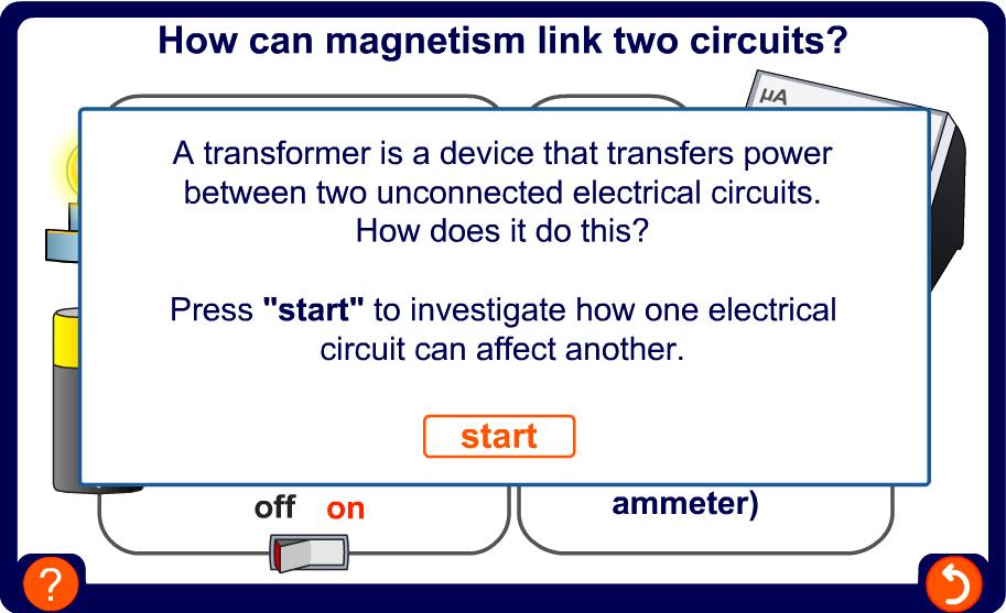
Transformers 1 of 25 Boardworks Ltd 2016
 Transformers 1 of 25 Boardworks Ltd 2016 Transformers 2 of 25 Boardworks Ltd 2016 Linking circuits with magnetism 3 of 25 Boardworks Ltd 2016 Transformers 4 of 25 Boardworks Ltd 2016 Power can be transferred
Copper and Electricity: Transformers and. the Grid. Transformers
 PHYSICS Copper and Electricity: Transformers and 16-18 YEARS the Grid Transformers Using transformers We use transformers to change the size of a voltage. We can step the voltage down from a high voltage
Unit Transformers
 Unit 11.08 Transformers Prepared in Dec 1998 Second editing in march 2000 Learning objectives At the end of this unit you should be able to : 1. describe the structure and principle of operation of a basic
Electromagnetic Induction. Transformer 5/16/11
 ransformer Content 23.1 Principles of electromagnetic induction 23.2 he a.c. generator 23.3 he transformer Learning Outcomes Candidates should be able to: (a) describe an experiment which shows that a
Experiment 6. Electromagnetic Induction and transformers
 Experiment 6. Electromagnetic Induction and transformers 1. Purpose Confirm the principle of electromagnetic induction and transformers. 2. Principle The PASCO scientific SF-8616 Basic Coils Set and SF-8617
1 K Hinds 2012 TRANSFORMERS
 1 K Hinds 2012 TRANSFORMERS A transformer changes electrical energy of a given voltage into electrical energy at a different voltage level. It consists of two coils which are not electrically connected,
Table of Contents. Table of Figures. Table of Tables
 Abstract The aim of this report is to investigate and test a transformer and check if it is good to use by doing the following tests continuity test, insulation test, polarity test, open circuit test,
I p = V s = N s I s V p N p
 UNIT G485 Module 1 5.1.3 Electromagnetism 11 For an IDEAL transformer : electrical power input = electrical power output to the primary coil from the secondary coil Primary current x primary voltage =
TRANSFORMER OPERATION
 Chapter 3 TRANSFORMER OPERATION 1 A transformer is a static device (no moving parts) used to transfer energy from one AC circuit to another. This transfer of energy may involve an increase or decrease
Inductors and Transformers
 MEHRAN UNIVERSITY OF ENGINEERING AND TECHNOLOGY, JAMSHORO DEPARTMENT OF ELECTRONIC ENGINEERING ELECTRONIC WORKSHOP # 05 Inductors and Transformers Roll. No: Checked by: Date: Grade: Object: To become familiar
Name the material used to make the core of the transformer.... (1) The primary coil has turns and the secondary coil 4000 turns.
 The primary coil has turns and the secondary coil 4000 turns.") Q. The diagram below shows a transformer. (i) Name the material used to make the core of the transformer. () The primary coil has 48 000 turns and the secondary coil 4000 turns. If the input voltage is
Q. The diagram below shows a transformer. (i) Name the material used to make the core of the transformer. () The primary coil has 48 000 turns and the secondary coil 4000 turns. If the input voltage is
PHYS 1442 Section 004 Lecture #15
 PHYS 1442 Section 004 Lecture #15 Monday March 17, 2014 Dr. Andrew Brandt Chapter 21 Generator Transformer Inductance 3/17/2014 1 PHYS 1442-004, Dr. Andrew Brandt Announcements HW8 on Ch 21-22 will be
In this lecture. Electromagnetism. Electromagnetism. Oersted s Experiment. Electricity & magnetism are different aspects of the same basic phenomenon:
 In this lecture Electromagnetism Electromagnetic Effect Electromagnets Electromechanical Devices Transformers Electromagnetic Effect Electricity & magnetism are different aspects of the same basic phenomenon:
Producing Electric Current
 Electromagnetic Induction Working independently in 181, Michael Faraday in Britain and Joseph Henry in the United States both found that moving a loop of wire through a magnetic field caused an electric
PHYS 1444 Section 501 Lecture #20
 PHYS 1444 Section 501 Lecture #0 Monday, Apr. 17, 006 Transformer Generalized Faraday s Law Inductance Mutual Inductance Self Inductance Inductor Energy Stored in the Magnetic Field 1 Announcements Quiz
Transformers. Objectives
 Transformers Objectives Explain mutual inductance Describe how a transformer is constructed and how it works Explain how a step-up transformer works Explain how a step-down transformer works Discuss the
TRANSFORMER THEORY. Mutual Induction
 Transformers Transformers are used extensively for AC power transmissions and for various control and indication circuits. Knowledge of the basic theory of how these components operate is necessary to
Look over Chapter 31 sections 1-4, 6, 8, 9, 10, 11 Examples 1-8. Look over Chapter 21 sections Examples PHYS 2212 PHYS 1112
 PHYS 2212 Look over Chapter 31 sections 1-4, 6, 8, 9, 10, 11 Examples 1-8 PHYS 1112 Look over Chapter 21 sections 11-14 Examples 16-18 Good Things To Know 1) How AC generators work. 2) How to find the
PHYS 1441 Section 001 Lecture #22 Wednesday, Nov. 29, 2017
 PHYS 1441 Section 001 Lecture #22 Chapter 29:EM Induction & Faraday s Law Transformer Electric Field Due to Changing Magnetic Flux Chapter 30: Inductance Mutual and Self Inductance Energy Stored in Magnetic
Exercise 10. Transformers EXERCISE OBJECTIVE DISCUSSION OUTLINE DISCUSSION. Introduction to transformers
 Exercise 10 Transformers EXERCISE OBJECTIVE When you have completed this exercise, you will be familiar with the basic operating principles of transformers, as well as with the different ratios of transformers:
The topics in this unit are:
 The topics in this unit are: 1 Static electricity 2 Repulsion and attraction 3 Electric circuits 4 Circuit symbols 5 Currents 6 Resistance 7 Thermistors and light dependent resistors 8 Series circuits
Electromagnetic Induction. Chapter 37
 Electromagnetic Induction Chapter 37 Wire moves past magnetic field Field moves past wire a voltage is produced. Electromagnetic induction Magnetism is not the source of voltage the wire is not the source
Review 6. unlike poles cause the magnets to attract. like poles cause the magnets to repel.
 Review 6 1. The two characteristics of all magnets are: they attract and hold Iron, and, if free to move, they will assume roughly a south - north position. 2. Lines of flux always leave the north pole
Electromagnetic Oscillations and Currents. March 23, 2014 Chapter 30 1
 Electromagnetic Oscillations and Currents March 23, 2014 Chapter 30 1 Driven LC Circuit! The voltage V can be thought of as the projection of the vertical axis of the phasor V m representing the time-varying
Lab 8 - Electric Transformer
 Lab 8 - Electric Transformer Safety and Equipment No special safety precautions are necessary for this lab. Computer with PASCO 850 Universal Interface and PASCO Capstone Magnetic Coil and Core Set 100
Electrical Theory 2 Lessons for Fall Semester:
 Electrical Theory 2 Lessons for Fall Semester: Lesson 1 Magnetism Lesson 2 Introduction to AC Theory Lesson 3 Lesson 4 Capacitance and Capacitive Reactance Lesson 5 Impedance and AC Circuits Lesson 6 AC
CHAPTER 13 REVIEW. Knowledge. Understanding
 CHAPTER 13 REVIEW K/U Knowledge/Understanding T/I Thinking/Investigation C Communication A Application Knowledge For each question, select the best answer from the four alternatives. 1. Which of the following
Trade of Electrician. The Transformer
 Trade of Electrician Standards Based Apprenticeship The Transformer Phase 2 Module No. 2.1 Unit No. 2.1.10 COURSE NOTES Created by Gerry Ryan - Galway TC Revision 1 April 2000 by Gerry Ryan - Galway TC
Engineering Science OUTCOME 4 - TUTORIAL 3 CONTENTS. 1. Transformers
 Unit : Unit code: QCF Level: 4 Credit value: 5 SYLLABUS Engineering Science L/60/404 OUTCOME 4 - TUTOIAL 3 Be able to apply single phase AC theory to solve electrical and electronic engineering problems
Transformers. ELG3311: Habash,
 Transformers A transformer is a device that changes AC electric power at one voltage level to AC electric power at another voltage level through the action of magnetic field. t consists of two or more
Paper number: Principles of electrical and electronics technology Paper series: December Practice
 Paper number: 850-56 Paper series: December 04 Question Syllabus reference Question 0.0 a) i) Tesla. ii) Newton. iii) Henry. Marks mark each 4 0.0 0.0 0.0 i) Megavolt ii) Microvolt. a) Directly Inversely
ELECTROMAGNETIC INDUCTION
 NAME SCHOOL INDEX NUMBER DATE ELECTROMAGNETIC INDUCTION 1. 1995 Q5 P2 (a) (i) State the law of electromagnetic induction ( 2 marks) (ii) Describe an experiment to demonstrate Faraday s law (4 marks) (b)
Bakiss Hiyana binti Abu Bakar JKE, POLISAS BHAB
 1 Bakiss Hiyana binti Abu Bakar JKE, POLISAS 1. Explain AC circuit concept and their analysis using AC circuit law. 2. Apply the knowledge of AC circuit in solving problem related to AC electrical circuit.
Electromagnetic Induction
 Chapter 16 Electromagnetic Induction In This Chapter: Electromagnetic Induction Faraday s Law Lenz s Law The Transformer Self-Inductance Inductors in Combination Energy of a Current-Carrying Inductor Electromagnetic
SPH3U UNIVERSITY PHYSICS
 SPH3U UNIVERSITY PHYSICS ELECTRICITY & MAGNETISM L Faraday s Discovery (P.588-591) Faraday s Discovery In 1819, when Oersted demonstrated the ability of a steady current to produce a steady magnetic field,
PHYS 1444 Section 003 Lecture #19
 PHYS 1444 Section 003 Lecture #19 Monday, Nov. 14, 2005 Electric Generators DC Generator Eddy Currents Transformer Mutual Inductance Today s homework is homework #10, due noon, next Tuesday!! 1 Announcements
General Physics (PHY 2140)
") General Physics (PHY 2140) Lecture 11 Electricity and Magnetism AC circuits and EM waves Resonance in a Series RLC circuit Transformers Maxwell, Hertz and EM waves Electromagnetic Waves 6/18/2007 http://www.physics.wayne.edu/~alan/2140website/main.htm
General Physics (PHY 2140) Lecture 11 Electricity and Magnetism AC circuits and EM waves Resonance in a Series RLC circuit Transformers Maxwell, Hertz and EM waves Electromagnetic Waves 6/18/2007 http://www.physics.wayne.edu/~alan/2140website/main.htm
DESIGN AND CONSTRUCTION OF 1500VA VARIABLE OUTPUT STEP DOWN TRANSFORMER
 DESIGN AND CONSTRUCTION OF 1500VA VARIABLE OUTPUT STEP DOWN TRANSFORMER OGUNDARE AYOADE B., OMOGOYE O. SAMUEL & OLUWASANYA OMOTAYO J. Department of Electrical/Electronic engineering, Lagos State Polytechnic,
Electric Transformer. Specifically, for each coil: Since the rate of change in flux through single loop of each coil are approximately the same,
 Electric Transformer Safety and Equipment Computer with PASCO 850 Universal Interface and PASCO Capstone Coils Set 3 Double Banana Cables PASCO Voltage Sensor (DIN to Banana cable with slip-on Alligator
Q1. (a) The drawing shows a small transformer used to recharge the battery in a 4.2 V mobile phone from a 230 V mains supply.
 The drawing shows a small transformer used to recharge the battery in a 4.2 V mobile phone from a 230 V mains supply.") Q1. (a) The drawing shows a small transformer used to recharge the battery in a 4.2 V mobile phone from a 230 V mains supply. Explain how you know that this is a step-down transformer....... (b) A transformer
Q1. (a) The drawing shows a small transformer used to recharge the battery in a 4.2 V mobile phone from a 230 V mains supply. Explain how you know that this is a step-down transformer....... (b) A transformer
Electromagnet Motor Generator
 Magnetism and Electromagnetic Induction Study Guide Chapter 36 & 37 Key Terms: Magnetic Pole Magnetic Field Magnetic Domain Electromagnet Motor Generator Electromagnetic Induction Faraday s Law Transformer
Generators and Alternating Current
 Generators and Alternating Current If one end of a magnet is moved in and out of a coil of wire, the induced voltage alternates in direction. The greater the frequency with which the magnet moves in and
GraspIT AQA GCSE Magnetism and Electromagnetism - ANSWERS
 A. Permanent and Induced Magnetism, Magnetic Forces and Fields 1. The following question is about magnets. a. Iron is a magnetic material. Name two other magnetic elements. (2) Cobalt (1) Nickel (1) b.
CH 1. Large coil. Small coil. red. Function generator GND CH 2. black GND
 Experiment 6 Electromagnetic Induction "Concepts without factual content are empty; sense data without concepts are blind... The understanding cannot see. The senses cannot think. By their union only can
Alternating Current. Slide 1 / 69. Slide 2 / 69. Slide 3 / 69. Topics to be covered. Sources of Alternating EMF. Sources of alternating EMF
 Slide 1 / 69 lternating urrent Sources of alternating EMF Transformers ircuits and Impedance Topics to be covered Slide 2 / 69 LR Series ircuits Resonance in ircuit Oscillations Sources of lternating EMF
Alternating Current. Slide 2 / 69. Slide 1 / 69. Slide 3 / 69. Slide 4 / 69. Slide 6 / 69. Slide 5 / 69. Topics to be covered
 Slide 1 / 69 lternating urrent Sources of alternating EMF ircuits and Impedance Slide 2 / 69 Topics to be covered LR Series ircuits Resonance in ircuit Oscillations Slide 3 / 69 Sources of lternating EMF
Transformer circuit calculations
 Transformer circuit calculations This worksheet and all related files are licensed under the Creative Commons Attribution License, version 1.0. To view a copy of this license, visit http://creativecommons.org/licenses/by/1.0/,
VOLTECHNOTES. Transformer Basics VPN /1
 Transformer Basics VPN 104-039/1 TRANSFORMER BASICS Introduction Transformer design and test are sometimes viewed as an art rather than a science. Transformers are imperfect devices, and there will be
Name: Lab Partner: Section: The purpose of this lab is to study induction. Faraday s law of induction and Lenz s law will be explored. B = B A (8.
 Chapter 8 Induction - Faraday s Law Name: Lab Partner: Section: 8.1 Purpose The purpose of this lab is to study induction. Faraday s law of induction and Lenz s law will be explored. 8.2 Introduction It
Transformers. Dr. Gamal Sowilam
 Transformers Dr. Gamal Sowilam OBJECTIVES Become familiar with the flux linkages that exist between the coils of a transformer and how the voltages across the primary and secondary are established. Understand
P202/219 Laboratory IUPUI Physics Department INDUCED EMF
 INDUCED EMF BJECIVE o obtain a qualitative understanding of Faraday s Law of Electromagnetic Induction and Lenz s Law of Induced Current by constructing a simple transformer. EQUIMEN wo identical coils,
17-2 Electromagnetic Induction
 17-2 Electromagnetic Induction Magnetic Flux and Induced Voltage Flux: The number of magnetic field lines passing through a given area. flux (area)(perpendicular component of the magnetic field) or AB
TRANSFORMERS INTRODUCTION
 Tyco Electronics Corporation Crompton Instruments 1610 Cobb International Parkway, Unit #4 Kennesaw, GA 30152 Tel. 770-425-8903 Fax. 770-423-7194 TRANSFORMERS INTRODUCTION A transformer is a device that
ECE 241L Fundamentals of Electrical Engineering. Experiment 8 A-C Transformer, Magnetization & Hysteresis
 ECE 241L Fundamentals of Electrical Engineering Experiment 8 A-C Transformer, Magnetization & Hysteresis A. Objectives: I. Measure leakage inductance and resistance loss II. Measure magnetization inductance
By Gill ( ) PDF created with FinePrint pdffactory trial version
 PDF created with FinePrint pdffactory trial version") By Gill (www.angelfire.com/al4/gill ) 1 Introduction One of the main reasons of adopting a.c. system instead of d.c. for generation, transmission and distribution of electrical power is that alternatin
By Gill (www.angelfire.com/al4/gill ) 1 Introduction One of the main reasons of adopting a.c. system instead of d.c. for generation, transmission and distribution of electrical power is that alternatin
Lesson 3: Electronics & Circuits
 Lesson 3: Electronics & Circuits Preparation for Amateur Radio Technician Class Exam Topics Review Ohm s Law Energy & Power Circuits Inductors & Inductance Capacitors & Capacitance Analog vs Digital Exam
Transformers. Department of Physics & Astronomy Texas Christian University, Fort Worth, TX. April 23, 2013
 Transformers Department of Physics & Astronomy Texas Christian University, Fort Worth, TX April 23, 2013 1 Introduction In the early nineteenth century, Hans Christian Øersted discovered that a magnetic
Chapter 24. Alternating Current Circuits
 Chapter 24 Alternating Current Circuits Objective of Lecture Generators and Motors Inductance RL Circuits (resistance and inductance) Transformers AC REMINDER: WORK ON THE EXAMPLES Read physics in perspective
n = V1 n = V2 110 = So the output current will be times the input current = = 123 Amp (ANS)
") Unit 4 Physics 016 14. Transformers and transmission Page 1 of 6 Checkpoints Chapter 14 and transmission. Question 556 Transformers This is a step down transformer, because the output voltage is less than
Unit 4 Physics 016 14. Transformers and transmission Page 1 of 6 Checkpoints Chapter 14 and transmission. Question 556 Transformers This is a step down transformer, because the output voltage is less than
Walchand Institute of Technology. Basic Electrical and Electronics Engineering. Transformer
 Walchand Institute of Technology Basic Electrical and Electronics Engineering Transformer 1. What is transformer? explain working principle of transformer. Electrical power transformer is a static device
Cornerstone Electronics Technology and Robotics Week 32 Transformers
 Cornerstone Electronics Technology and Robotics Week 32 Transformers Administration: o Prayer o Turn in quiz Electricity and Electronics, Section 12.1, Transformer Theory: o A transformer is a device that
A 11/89. Instruction Manual and Experiment Guide for the PASCO scientific Model SF-8616 and 8617 COILS SET. Copyright November 1989 $15.
 Instruction Manual and Experiment Guide for the PASCO scientific Model SF-8616 and 8617 012-03800A 11/89 COILS SET Copyright November 1989 $15.00 How to Use This Manual The best way to learn to use the
Chapter 16: Mutual Inductance
 Chapter 16: Mutual Inductance Instructor: Jean-François MILLITHALER http://faculty.uml.edu/jeanfrancois_millithaler/funelec/spring2017 Slide 1 Mutual Inductance When two coils are placed close to each
Faraday Laws of Electromagnetic Induction CLIL LESSON
 Faraday Laws of Electromagnetic Induction CLIL LESSON Experimental trials Michael Faraday-1931 This law shows the relationship between electric circuit and magnetic field A coil is connected to a galvanometer
SECTION 3 BASIC AUTOMATIC CONTROLS UNIT 12 BASIC ELECTRICITY AND MAGNETISM. Unit Objectives. Unit Objectives 2/29/2012
 SECTION 3 BASIC AUTOMATIC CONTROLS UNIT 12 BASIC ELECTRICITY AND MAGNETISM Unit Objectives Describe the structure of an atom. Identify atoms with a positive charge and atoms with a negative charge. Explain
Basics of electrical transformer
 Visit: https://engineeringbasic.com Complete basics and theory of Electrical Transformer Electrical Transformer is the most used electrical machine in power system. Both in the power transmission and distribution
Single-Phase Transformation Review
 Single-Phase Transformation Review S T U D E N T M A N U A L March 2, 2005 2 STUDENT TRAINING MANUAL Prerequisites: None Objectives: Given the Construction Standards manual and a formula sheet, you will
CHAPTER 5 CONCEPTS OF ALTERNATING CURRENT
 CHAPTER 5 CONCEPTS OF ALTERNATING CURRENT INTRODUCTION Thus far this text has dealt with direct current (DC); that is, current that does not change direction. However, a coil rotating in a magnetic field
Chapter 21. Alternating Current Circuits and Electromagnetic Waves
 Chapter 21 Alternating Current Circuits and Electromagnetic Waves AC Circuit An AC circuit consists of a combination of circuit elements and an AC generator or source The output of an AC generator is sinusoidal
END-OF-SUBCOURSE EXAMINATION
 END-OF-SUBCOURSE EXAMINATION Circle the letter of the correct answer to each question. When you have answered all of the questions, use a Number 2 pencil to transfer your answers to the TSC Form 59. 1.
5.0 THREE PHASE SYSTEM
 5.0 THREE PHASE SYSTEM ET 201 BAKISS HIYANA BAU BAKAR JKE, POLISAS 1 COURSE LEARNING OUTCOME 1. Explain AC circuit concept and their analysis using AC circuit law. 2. Apply the knowledge of AC circuit
Magnetism Quiz. Name: Class: Date: ID: A. Multiple Choice Identify the choice that best completes the statement or answers the question.
 Name: Class: Date: ID: A Magnetism Quiz Multiple Choice Identify the choice that best completes the statement or answers the question. 1. Electric current can best be induced in a wire by a. stretching
Alternating Current Page 1 30
 Alternating Current 26201 11 Page 1 30 Calculate the peak and effective voltage of current values for AC Calculate the phase relationship between two AC waveforms Describe the voltage and current phase
AEIJST - January Vol 5 - Issue 01 ISSN Minimization Iron Losses in Transformer
 Abstract Minimization Iron Losses in Transformer *P.Ramesh *MIE, MISTE It is almost impossible to reduce the iron losses completely; however these can be reduced to a certain extent. Here we have made
AP Physics C. Alternating Current. Chapter Problems. Sources of Alternating EMF
 AP Physics C Alternating Current Chapter Problems Sources of Alternating EMF 1. A 10 cm diameter loop of wire is oriented perpendicular to a 2.5 T magnetic field. What is the magnetic flux through the
Today: Finish Chapter 24. Begin Chapter 25 (Magnetic Induction)
") Today: Finish Chapter 24 Begin Chapter 25 (Magnetic Induction) Next Homework posted, due next Fri Dec 11 Electromagnetic Induction Voltage can be induced (created) by a changing magnetic field. C.f. last
Today: Finish Chapter 24 Begin Chapter 25 (Magnetic Induction) Next Homework posted, due next Fri Dec 11 Electromagnetic Induction Voltage can be induced (created) by a changing magnetic field. C.f. last
Power. Power is the rate of using energy in joules per second 1 joule per second Is 1 Watt
 3 phase Power All we need electricity for is as a source of transport for energy. We can connect to a battery, which is a source of stored energy. Or we can plug into and electric socket at home or in
12/6/2011. Electromagnetic Induction. Electromagnetic Induction and Electromagnetic Waves. Checking Understanding. Magnetic Flux. Lenz s Law.
 Electromagnetic Induction and Electromagnetic Waves Topics: Electromagnetic induction Lenz s law Faraday s law The nature of electromagnetic waves The spectrum of electromagnetic waves Electromagnetic
Basic Circuitry and X ray Production. Lynn C. Sadler, MSRS, R.T.(R)(QM) President, WCEC, Inc.
(QM) President, WCEC, Inc.") Basic Circuitry and X ray Production Lynn C. Sadler, MSRS, R.T.(R)(QM) President, WCEC, Inc. X Ray Production What are X Rays? Where do they come from? What are some characteristics of x radiation? How
Basic Circuitry and X ray Production Lynn C. Sadler, MSRS, R.T.(R)(QM) President, WCEC, Inc. X Ray Production What are X Rays? Where do they come from? What are some characteristics of x radiation? How
Exercises of resistors 1. Calculate the resistance of a 10 m long Copper wire with diameter d = 1.0 mm.
 Exercises of resistors 1. Calculate the resistance of a 10 m long Copper wire with diameter d = 1.0 mm. 2. Calculate the resistances of following equipment: using 220V AC a) a 1000 W electric heater b)
ESO 210 Introduction to Electrical Engineering
 ESO 210 Introduction to Electrical Engineering Lecture-19 Magnetic Circuits and Introduction to Transformers 2 SERIES CONNECTION OF MUTUALLY COUPLED COILS A mutual term will alter the total inductance
Wireless Inductive Power Transfer
 Wireless Inductive Power Transfer Ranjithkumar R Research associate, electrical, Rustomjee academy for global careers, Maharashtra, India ABSTRACT The inductive power transfer (IPT) system is introduced
Intermediate Physics PHYS102
 Intermediate Physics PHYS102 Dr Richard H. Cyburt Assistant Professor of Physics My office: 402c in the Science Building My phone: (304) 384-6006 My email: rcyburt@concord.edu My webpage: www.concord.edu/rcyburt
APPLICATION NOTE - 018
 APPLICATION NOTE - 018 Power Transformers Background Power Transformers are used within an AC power distribution systems to increase or decrease the operating voltage to achieve the optimum transmission
Electrical Theory. Power Principles and Phase Angle. PJM State & Member Training Dept. PJM /22/2018
 Electrical Theory Power Principles and Phase Angle PJM State & Member Training Dept. PJM 2018 Objectives At the end of this presentation the learner will be able to: Identify the characteristics of Sine
Practical Tricks with Transformers. Larry Weinstein K0NA
 Practical Tricks with Transformers Larry Weinstein K0NA Practical Tricks with Transformers Quick review of inductance and magnetics Switching inductive loads How many voltages can we get out of a $10 Home
Alternating current circuits- Series RLC circuits
 FISI30 Física Universitaria II Professor J.. ersosimo hapter 8 Alternating current circuits- Series circuits 8- Introduction A loop rotated in a magnetic field produces a sinusoidal voltage and current.
Review: Lecture 9. Instantaneous and Average Power. Effective or RMS Value. Apparent Power and Power Factor. Complex Power. Conservation of AC Power
 Review: Lecture 9 Instantaneous and Average Power p( t) VmI m cos ( v i ) VmI m cos ( t v i ) Maximum Average Power Transfer Z L R L jx Effective or RMS Value I rms I m L R P * TH Apparent Power and Power
4. The circuit in an appliance is 3A and the voltage difference is 120V. How much power is being supplied to the appliance?
 1 Name: Date: / / Period: Formulas I = V/R P = I V E = P t 1. A circuit has a resistance of 4Ω. What voltage difference will cause a current of 1.4A to flow in the 2. How many amperes of current will flow
What is an Inductor? Token Electronics Industry Co., Ltd. Version: January 16, Web:
 Version: January 16, 2017 What is an Inductor? Web: www.token.com.tw Email: rfq@token.com.tw Token Electronics Industry Co., Ltd. Taiwan: No.137, Sec. 1, Zhongxing Rd., Wugu District, New Taipei City,
13. Magnetically Coupled Circuits
 13. Magnetically Coupled Circuits The change in the current flowing through an inductor induces (creates) a voltage in the conductor itself (self-inductance) and in any nearby conductors (mutual inductance)
AP Physics Electricity and Magnetism #7 Inductance
 Name Period AP Physics Electricity and Magnetism #7 Inductance Dr. Campbell 1. Do problems Exercise B page 589 and problem 2, 3, 8, 9 page 610-1. Answers at the end of the packet. 2. A 20-turn wire coil
E) all of the above E) 1.9 T
 all of the above E) 1.9 T") 1. The figure shows a uniform magnetic field that is normal to the plane of a conducting loop, which has a resistance R. Which one of the following changes will cause an induced current to flow through
1. The figure shows a uniform magnetic field that is normal to the plane of a conducting loop, which has a resistance R. Which one of the following changes will cause an induced current to flow through
CITY UNIVERSITY OF HONG KONG
 CITY UNIVERSITY OF HONG KONG Modeling and Analysis of the Planar Spiral Inductor Including the Effect of Magnetic-Conductive Electromagnetic Shields Submitted to Department of Electronic Engineering in
15. the power factor of an a.c circuit is.5 what will be the phase difference between voltage and current in this
 1 1. In a series LCR circuit the voltage across inductor, a capacitor and a resistor are 30 V, 30 V and 60 V respectively. What is the phase difference between applied voltage and current in the circuit?
PHYSICS VCE UNITS 3&4 DIAGNOSTIC TOPIC TESTS 2017
 PHYSICS VCE UNITS 3&4 DIAGNOSTIC TOPIC TESTS 2017 TEST 3: TOTAL 45 MARKS (45 MINUTES) Student s Name: Teacher s Name: Directions to students Write your name and your teacher s name in the spaces provided
~=E.i!=h. Pre-certification Transformers
 7 Transformers Section 26 of the electrical code governs the use and installations of transformers. A transformer is a static device used to transfer energy from one alternating current circuit to another.
CHAPTER 8: ELECTROMAGNETISM
 CHAPTER 8: ELECTROMAGNETISM 8.1: MAGNETIC EFFECT OF A CURRENT-CARRYING CONDUCTOR Electromagnets 1. Conductor is a material that can flow.. 2. Electromagnetism is the study of the relationship between.and..
Chapter 11. Alternating Current
 Unit-2 ECE131 BEEE Chapter 11 Alternating Current Objectives After completing this chapter, you will be able to: Describe how an AC voltage is produced with an AC generator (alternator) Define alternation,