OUTLINE. Introduction. Introduction. Conducted Electromagnetic Interference in Smart Grids. Introduction. Introduction
|
|
|
- Sharleen Fisher
- 5 years ago
- Views:
Transcription


.")
1 Robert Smoleński Institute of Electrical Engineering University of Zielona Gora Conducted Electromagnetic Interference in Smart Grids Introduction Currently there is lack of the strict, established definition of the Smart Grid, furthermore, Smart Grid concepts presented by the individual authorities in the field of power systems differ significantly. On the basis of the literature study, the Smart Grid can be described as the power system that in a detail perspective should posses specific possibilities and characteristics. The grid should allow integration of the bigger amount of the energy ergy from renewable energy sources. The typical feature of this system is a high quality of electric energy, elimination of higher harmonics, voltage dips, sags and interruptions, tions, asymmetry of phase voltages. End-users perform in Smart Grids an active role, they are both users and producers of electric energy (Smart Buildings, Smart Cities). Smart Grid has to be ready for new challenges such as, for instance, nce, development of electric vehicles market (V2G). OUTLINE Introduction Introduction Power Electronic Interfaces in Smart Grids Standardized measurements of conducted EMI Conducted EMI issues in Smart Grids Shaping of the EMI characteristics in Smart Grids Compensation of interference sources inside of the Power Electronic Conclusions Introduction Introduction
![Average Detector Level [dbuv] 110 100 90 Drive 1 (Level dbuv) Drive 2 (Level dbuv) Drive 3 (Level dbuv) Max Min 75% 25% 50% Max Min 75%](/docs-images/83/88583689/images/2-0.jpg "50% 25% Max 75% 50% 25% Min Average Detector Level [dbuv] 110 100 90 Drive 1&2 (Level dbuv) Drive 2&3 (Level dbuv) Drive 1&3 (Level dbuv)")

 b.) Box charts: a.")
 for groups of drives EMC of the Smart Grid is Important Issue President of the SC1 Magnus Olofsson Director-General Swedish National")
2 Average Detector Level [dbuv] Drive 1 (Level dbuv) Drive 2 (Level dbuv) Drive 3 (Level dbuv) Max Min 75% 25% 50% Max Min 75% 50% 25% Max 75% 50% 25% Min Average Detector Level [dbuv] Drive 1&2 (Level dbuv) Drive 2&3 (Level dbuv) Drive 1&3 (Level dbuv) Drive 1&2&3 (Level dbuv) Max Max 75% 75% 50% 50% 25% 25% Min Max Min 75% 50% 25% Max 75% 50% 25% Min Main EMC issues in systems containing ing Power Electronics Interfaces: Connection of high emission power electronic converters to susceptible control and monitoring equipment that might cause immunity problems Aggregation of interferences caused by group of converters Spread of interferences over wide circuits Min 80 Drive 1 Drive 2 Drive 3 80 Drive 1&2 Drive 2&3 Drive 1&3 Drive 1&2&3 a.) b.) Box charts: a.) for single dirives, b.) for groups of drives EMC of the Smart Grid is Important Issue President of the SC1 Magnus Olofsson Director-General Swedish National Electrical Safety Board Power Electronic Interfaces in Smart Grids EMI couplings: -inductive -capacitive -by common impedance Source: EMC compliance club

 of determined amplitude A, pulse (pulse train of amplitude A, duration ti, pulse repetition rate")
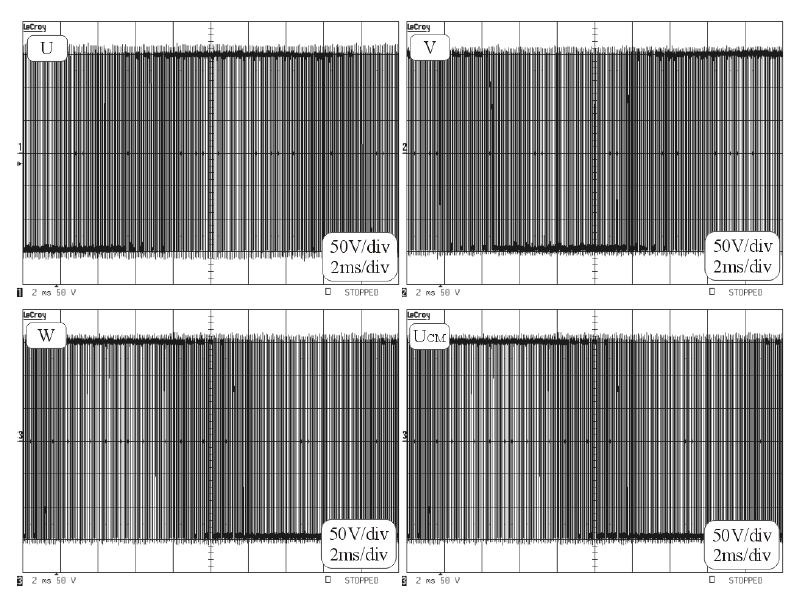
3 Phase voltages and common mode voltage at the output of the 3-phase 3 inverter Bearing race damages caused by EDM currents Standardized measurements of conducted EMI Phase voltage and common mode current Standardized measurements of conducted EMI Originally principles of electromagnetic compatibility focused on assurance of the proper RTV signal reception. Therefore the usage of equipment that during EMC test simulate a typical RTV receiver seemed to be appropriate approach. The standard describe responses of the receiver for the selected signals: sinusoidal (continuous wave) of determined amplitude A, pulse (pulse train of amplitude A, duration ti, pulse repetition rate fr), noise (normal distribution of amplitude probability). CM voltage U CM, shaft voltage and CM current I CM, time-expanded expanded scale shaft voltage U S and EDM E current I B Main circuit diagram of the 4-quadrant 4 inverter drive system
, intermodulation effects, limitation of noises and")
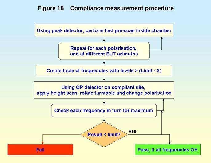
4 Standardized measurements of conducted EMI Standardized measurements of conducted EMI The EMI receiver has to meet standard requirements concerning especially: pulse response, selectivity (band pass in individual frequency ranges, attenuation of intermediate frequency signals, attenuation of mirror frequencies and other unwanted responses), intermodulation effects, limitation of noises and internal unwanted signals (internal noises, continuous wave signals), shielding IF BW filter Standardized measurements of conducted EMI Superheterodyne receiver The block diagram of the typical EMI receiver Resolution of the EMI reciver scan Standardized measurements of conducted EMI Standardized measurements of conducted EMI Differences between EMI receiver and digital oscilloscope!!! The functional blocks of the typical EMI receiver The peak detector offers fastest possible sweep due to shortest time constant of the RC circuit The usage of the peak detector sweep is fast and easy way to compare obtained results with limit lines during engineering test, because peak detector values are always higher or equal to average and quasi-peak detectors indication!!! Peak detector diagram

5 Standardized measurements of conducted EMI Standardized measurements of conducted EMI The quasi-peak detection mode rely on utilization of the integration circuit of two different time constants in order to evaluate so-called annoyance factor. The charge rate of the quasi-peak detector is much faster than the discharge rate, thus the higher the repetition rate of the signal, the higher the output of the quasi-peak detector. Quasi-peak detector diagram LISN (Line Impedance Stabilization Network ) Standardized measurements of conducted EMI Standardized measurements of conducted EMI For average detection the peak detected signal must pass through a filter with a bandwidth much less than the resolution bandwidth. The filter averages the higher frequency components, such as noise, at the output of the envelope detector. Average detector diagram LISN (Line Impedance Stabilization Network ) Standardized measurements of conducted EMI What is the conducted EMI? What is LISN developed for? Standardized measurements of conducted EMI LISN (Line Impedance Stabilization Network ) Flow of the measured interference currents


6 Standardized measurements of conducted EMI Conducted EMI issues in Smart Grids LISN (Line Impedance Stabilization Network ) Scheme of four-quadrant frequency converter with AC generator Standardized measurements of conducted EMI Conducted EMI issues in Smart Grids LISN (Line Impedance Stabilization Network ) Conducted EMI spectra in CISPR A and CISPR B frequency ranges Conducted EMI issues in Smart Grids Conducted EMI issues in Smart Grids Conducted EMI spectrum for CISPR A frequency range
 in neutral, b.) load, c.")
7 Conducted EMI generated by 4-quadrant 4 frequency converters and EMI filters development Conducted EMI issues in Smart Grids a.) b.) c.) Conducted EMI spectrum (drive without filters): a.) in neutral, b.) load, c.) generator Phase voltages and CM voltage at the input terminals of the converter Conducted EMI issues in Smart Grids Conducted EMI issues in Smart Grids EMI spreading equivalent circuit Electric grid scheme with designated measuring points Conducted EMI issues in Smart Grids Conducted EMI issues in Smart Grids CM current on the line side of the converter: (a) expanded form, (b) wide range time scale Box-and and-whisker plot of quasi-peak detector measurements for: (a) interface turned off, (b) interface turned on
 switched off converter, (b) switched on converter MV and LV electric grid scheme with")
 in transformer station for switched-off converter Magnetic field")
 B CM impedance module of YAKY 4x25mm2 cable: 2.")
8 Conducted EMI issues in Smart Grids Spectra of current in PE wire of power cable at transformer terminal for: (a) switched off converter, (b) switched on converter MV and LV electric grid scheme with designated measuring points Spectra of current in PE wire: (a) near converter, (b) in transformer station for switched-on converter, (c) in transformer station for switched-off converter Magnetic field strength on both sides of power transformer: (a) low voltage side (point A), (b) medium voltage side (point B) B CM impedance module of YAKY 4x25mm2 cable: 2.5m, 5m and 10m long Magnetic field measurement under overhead MV line


9 Increase of interference caused by converter under MV overhead lines: l a) 20 m away from station, b) 1500 m away from station Passage of common mode currents through virtual grounding point Conducted EMI issues in Smart Grids Conducted EMI generated by 4-quadrant 4 frequency converters and EMI filters development Scheme of four-quadrant frequency converter with AC generator Spectrum of CM currents on line and motor side Conducted EMI generated by 4-quadrant 4 frequency converters and EMI filters development Conducted EMI generated by 4-quadrant 4 frequency converters and EMI filters development Experimental arrangement Four-quadrant drive with passive input filter
10 Conducted EMI generated by 4-quadrant 4 frequency converters and EMI filters development High emission in HF range Passage of common mode currents through virtual grounding point in drive with passive input filter Spectrum of CM currents on line and motor side (drive with input passive filter) Conducted EMI generated by 4-quadrant 4 frequency converters and EMI filters development Conducted EMI generated by 4-quadrant 4 frequency converters and EMI filters development Conducted EMI spectrum (drive with passive input filter) Spectrum of CM currents on line and motor side (drive with input and output passive filter) Conducted EMI spectrum (drive without filters and drive with passive input filter) Passage of common mode currents through virtual grounding point in drive with input and output passive filter

 Phase current and CM current Aggregated EMI generated by group of")

 and CM current (i(")

11 Conducted EMI generated by 4-quadrant 4 frequency converters and EMI filters development Aggregated EMI generated by group of 2-quadrant 2 asynchronous drives Conducted emission in both CISPR A and CISPR B ranges (drive with input and output passive filter) Phase current and CM current Aggregated EMI generated by group of 2-quadrant 2 asynchronous drives Measuring circumstances!!! Energy-efficient efficient fluorescent lamps story!!! Arrangement for measurements of conducted EMI generated by a group of converters with deterministic and random modulations Phase current (i( f ) and CM current (i( CM ) Aggregated EMI generated by group of 2-quadrant 2 asynchronous drives Aggregated EMI generated by group of 2-quadrant 2 asynchronous drives Main oscillatory modes of CM current in motor PE wire Spectrum of CM current on the line side
 one converter, b.) two converters, c.")
 R1, b) R2, c) R3, d) R1&R2, e) R1&R3, f) R2&R3 Aggregated EMI generated by group of 2-quadrant 2")
![asynchronous drives Average Detector Level [dbuv] 110 100 90 Drive 1 (Level dbuv) Drive 2 (Level dbuv) Drive 3 (Level](/docs-images/83/88583689/images/12-3.jpg "dbuv) Max Min 75% 25% 50% Max Min 75% 50% 25% Max 75% 50% 25% Min Average Detector Level [dbuv] 110 100 90 Drive 1&2")

 for groups of drives Spectra of aggregated interference (CISPR A) generated by three converters, measured using peak")
 D1, b) D2, c) D3, d) D1&D2, e) D1&D3,")
12 Aggregated EMI generated by group of 2-quadrant 2 asynchronous drives Spectrograms for inverter switching frequency: a.) one converter, b.) two converters, c.) three converters Conducted EMI spectra (CISPR A) measured using peak and average detectors for converters with random modulation: a) R1, b) R2, c) R3, d) R1&R2, e) R1&R3, f) R2&R3 Aggregated EMI generated by group of 2-quadrant 2 asynchronous drives Average Detector Level [dbuv] Drive 1 (Level dbuv) Drive 2 (Level dbuv) Drive 3 (Level dbuv) Max Min 75% 25% 50% Max Min 75% 50% 25% Max 75% 50% 25% Min Average Detector Level [dbuv] Drive 1&2 (Level dbuv) Drive 2&3 (Level dbuv) Drive 1&3 (Level dbuv) Drive 1&2&3 (Level dbuv) Max Max 75% 75% 50% 50% 25% 25% Min Max Min 75% 50% 25% Max 75% 50% 25% Min Min 80 Drive 1 Drive 2 Drive 3 80 Drive 1&2 Drive 2&3 Drive 1&3 Drive 1&2&3 a.) b.) Box charts: a.) for single dirives, b.) for groups of drives Spectra of aggregated interference (CISPR A) generated by three converters, measured using peak and average detectors for: a) deterministic modulation b) random modulation Conducted EMI spectra (CISPR A) measured using peak and average detectors for converters with deterministic modulation: a) D1, b) D2, c) D3, d) D1&D2, e) D1&D3, f) D2&D3 Conducted EMI spectra (CISPR B) measured using peak and average detectors for converters with deterministic modulation: a) D1, b) D2, c) D3, d) D1&D2, e) D1&D3, f) D2&D3
 R1, b) R2, c) R3, d) R1&R2, e) R1&R3,")
 generated by three converters, measured")

 IF")
13 Conducted EMI spectra measured using peak and average detectors for converters with random modulation: a) R1, b) R2, c) R3, d) R1&R2, e) R1&R3, f) R2&R3 DC/DC converter carrier based PWM, and interference currents Spectra of aggregated interference (CISPR B) generated by three converters, measured using peak and average detectors for: a) deterministic modulation b) random modulation DC/DC converter carrier based PWM, and interference currents Box-and-whisker plots of average detector measurements for various drive configurations with deterministic and random modulations and filter: (a) IF BW = 200 Hz, (b) IF BW=9kHz


14 The k-th harmonic of the total interference current generated by N converters can be expressed by: FFT of EMI current generated by DC/DC converters with deterministic tic modulation: a) single converter, b) three converters of the same switching frequency, c) three converters of slightly different switching frequency Construction of vector representing the k th harmonic of the sum of interference generated by three identical DC/DC converters FFT of EMI current generated by DC/DC converters with random modulation: a) single converter, b) three converters 3D density function describing probability of vector Zk placement for: 5, 15 and 30 convertersm of interference generated by three identical DC/DC converters Box-and-whisker plots of waiting times for critical transmission errors in a system with two operated converters with deterministic (D1&2) and random (R1&2) modulations
15 0,8 0,6 0, Current [A] 0,2 0-0,2 Voltage [V] ,4-0,6-0,8 0 2E-6 4E-6 6E-6 8E-6 1E-5 1,2E-5 1,4E-5 1,6E-5 1,8E-5 2E-5 Time [s] E-6 4E-6 6E-6 8E-6 1E-5 1,2E-5 1,4E-5 1,6E-5 1,8E-5 2E-5 Time [s] Interference current and RS-232 voltage signal Source: EMC compliance club Cables as close as possible Cables 4 cm away from each other Electron microscope story Impedance module of parasitic couplings between two cables Source: EMC compliance club Capacitor impedance module: a.) 3,3 nf, b.) 100 nf Impedamce module [Ω] cm 1 cm 2 cm 3 cm Impedance module [Ω] ,1 0 cm 1 cm 2 cm 3 cm 0,1 0,01 10k 100k 1M 10M 30M Frequency [Hz] 0,01 10k 100k 1M 10M Frequency [Hz] Source: EMC compliance club
, bearing voltage (U W ) and CM current (I CM ) in system without filters CM voltage in neutral point (U N ), bearing voltage (U W ) and CM current (I")
16 CM voltage in neutral point (U N ), bearing voltage (U W ) and CM current (I CM ) in system without filters Inductance increase cause damping factor decrease!!! CM voltage in neutral point (U N ), bearing voltage (U W ) and CM current (I CM ) in system without filters CM voltage in neutral point (U N ), bearing voltage (U W ) and CM current (I CM ) in system with line reactors
17 CM voltage in neutral point (U N ), bearing voltage (U W ) and CM current (I CM ) in system with CM choke CM voltage in neutral point (U N ), bearing voltage (U W ) and CM current (I CM ) in system with CM transformer EMC of 2-quadrant 2 frequency converters and EMI filters Source: S. Ogasawara, H. Akagi, Modelling and Damping of High-Frequency Leakage Currents in PWM Inverter-Fed AC Motor Drive Systems, IEEE Trans. on Ind. Appl. 32, (1996) Influence of passive filters on CM current shape and its RMS value Influence of passive filters on spectrum of CM current


18 Influence of passive filters on shaft voltages CM voltage at neutral point of the output of inverter U det and CM voltage at the output of emitter follower U D 3D distributions of EDM currents in drive with different passive filters Voltage drop on gate resistor!!! Drive system with series active filter CM voltage at neutral point of the output of inverter U det and CM voltage at the output of emitter follower U D
 and compensating voltage U D Inverter-fed system with passive CM voltage filter arrangement Line to line voltages at the")
 and compensating voltage U D CM voltage at neutral point of star-connected load in system: a) without filter, b) with")
19 Common mode voltage and shaft voltage in drive with series active filter Phase voltages on the series connected inductors (L fcm and L fdm ) and compensating voltage U D Inverter-fed system with passive CM voltage filter arrangement Line to line voltages at the output of the filter for inverter output frequency f inv =25 Hz and f inv =50 Hz Phase voltages on the series connected inductors (L fcm and L fdm ) and compensating voltage U D CM voltage at neutral point of star-connected load in system: a) without filter, b) with filter

 f inv =50 Hz, b) f inv =25 Hz,")

20 CM currents in drive: a) without filter, b) with passive CM voltage filter Phase voltages and CM voltages at the output of two-level inverter Compensated CM voltage ucm and magnetizing current im for various inverter output frequencies: a) f inv =50 Hz, b) f inv =25 Hz, c) f inv =0 Hz Phase voltages and CM voltages at the output of three-level inverter Compensated CM voltage ucm and magnetizing current im for various inverter output frequencies: a) f inv =50 Hz, b) f inv =25 Hz, c) f inv =0 Hz Phase voltages and CM voltages at the output of four-level inverter
![Amplitude [%] Amplitude [%] Passive CM filter with sinusoidal line-to-line voltages and CM choke saturation problems Modulation effect CM voltage in two-, three- and four level inverters Compensated](/docs-images/83/88583689/images/21-6.jpg "CM voltage and magnetizing current for inverter output frequency: 50 Hz, 25 Hz and 0 Hz 3D space vector representation of the switching states of a two- and three-level inverter Placement of")
 = 1 2 t 2 FP i N U CM = Frequency [Hz] 2 1 ( t) = P( t) + N i N 2 ( t) = 2 3N 1 N k= 1 i= 1 H Asin 2π finv t + 2 kπ 3")
21 Amplitude [%] Amplitude [%] Passive CM filter with sinusoidal line-to-line voltages and CM choke saturation problems Modulation effect CM voltage in two-, three- and four level inverters Compensated CM voltage and magnetizing current for inverter output frequency: 50 Hz, 25 Hz and 0 Hz 3D space vector representation of the switching states of a two- and three-level inverter Placement of triangular carrier functions for modulations: a) PD, b) APOD, c) POD Compensation conditions in multilevel inverters with carrier-based sinusoidal modulations Compensation conditions in multilevel inverters with carrier-based sinusoidal modulations Two-level Three-level 1 P( t) = 1 2 t 2 FP i N U CM = Frequency [Hz] 2 1 ( t) = P( t) + N i N 2 ( t) = 2 3N 1 N k= 1 i= 1 H Asin 2π finv t + 2 kπ 3 Modulation index Amplitude [%] i FPRN ( t) 1 Frequency [Hz] Frequency [Hz] Modulation index Modulation index Four-level Maximum time integral values vs. the inverter output frequencies and the modulation indexes
![Frequency [Hz] Compensation conditions in multilevel inverters with carrier-based sinusoidal modulations Compensation](/docs-images/83/88583689/images/22-0.jpg "conditions in multilevel inverters with carrier-based sinusoidal modulations a) b) c) Lowest level CM voltage and time t")

 b) c) Lowest level CM voltage and time integral of CM voltage produced, by five-level inverter for M=1: a) PD")

![Frequency [Hz] Modulation index Maximum time integral values vs.](/docs-images/83/88583689/images/22-10.jpg "the inverter output frequencies and the modulation indexes, for the five-level inverter, modulated using: a) PD, b) APOD, c)")
22 Frequency [Hz] Compensation conditions in multilevel inverters with carrier-based sinusoidal modulations Compensation conditions in multilevel inverters with carrier-based sinusoidal modulations a) b) c) Lowest level CM voltage and time t integral of CM voltage produced, by five-level inverter in worst case : : a) PD modulation, b) APOD modulation, c) POD modulation Theoretical evaluation and numerical analyses Compensation conditions in multilevel inverters with carrier-based sinusoidal modulations Proposed method of function root approximation and relative r error for different root determination methods a) b) c) Lowest level CM voltage and time integral of CM voltage produced, by five-level inverter for M=1: a) PD modulation, b) APOD modulation, c) POD modulation Compensation conditions in multilevel inverters with carrier-based sinusoidal modulations Amplitude [%] Amplitude [%] APOD PD Frequency [Hz] 20 Modulation index Amplitude [%] POD Modulation index Frequency [Hz] Modulation index Maximum time integral values vs. the inverter output frequencies and the modulation indexes, for the five-level inverter, modulated using: a) PD, b) APOD, c) POD a) Fast charging station arrangement, b) fast charging terminal developed in cooperation with IEE

23 Compensator arrangement with CM choke in DC link (C AC1,2,3=20nF, C DC1,2=500nF, L f1,2,3=100mh) b. DC-link-to-ground voltage ripples and collector-emitter emitter voltages Simulation scheme of AC/DC/DC power electronic interface Intrference filtration Simulation scheme of AC/DC/DC power electronic interface Compensator arrangement with CM choke in DC link (C AC1,2,3 =20nF, C DC1,2 =5µF, L f1,2 =5mH) CM choke inductance 20 times smaller!!! DC-link-to-ground voltage ripples and collector-emitter emitter voltages DC-link-to-ground voltage ripples and collector-emitter emitter voltages Compensator arrangement with three-phase input CM choke (C AC1,2,3 =20nF, C DC1,2 =500nF, L f1,2,3 =100mH) Compensator arrangement with CM choke in DC link (C AC1,2,3 =20nF, C DC1,2 =5µF, L f1,2 =5mH) Experimental results b. High overvoltage 600 Without filter 600 With filter DC-link-to-ground voltage ripples and collector-emitter emitter voltages Voltage [V] Voltage [V] µ 200µ 300µ 400µ 500µ 0 100µ 200µ 300µ 400µ 500µ Time [s] Time [s] Level [dbµv] Level [dbµv] x CISPR B 0 150k 300k 500k 1M 2M 3M 4M 6M 10M 30M Frequency [Hz] CISPR B 0 150k 300k 500k 1M 2M 3M 4M 6M 10M 30M Frequency [Hz]
24 Power electronic interface with sinusoidal output filter CM current in the generator PE wire, IfCM current and magnetizing g current Voltages of DC buses, DC link voltage and CM voltage in stator windings neutral point (drive without filters) Compensator of DC link-to-ground voltage ripples with CM choke in DC link Voltages of negative DC bus and CM voltage in stator windings neutral point (drive with sinusoidal filter) Compensator of DC link-to-ground voltage ripples with three-phase input CM choke

25 Placement of triangular carrier functions for modulations: a) PD, b) APOD, c) POD
26

27
28
29
30
Understanding and Optimizing Electromagnetic Compatibility in Switchmode Power Supplies
 Understanding and Optimizing Electromagnetic Compatibility in Switchmode Power Supplies 1 Definitions EMI = Electro Magnetic Interference EMC = Electro Magnetic Compatibility (No EMI) Three Components
SIMULATION of EMC PERFORMANCE of GRID CONNECTED PV INVERTERS
 SIMULATION of EMC PERFORMANCE of GRID CONNECTED PV INVERTERS Qin Jiang School of Communications & Informatics Victoria University P.O. Box 14428, Melbourne City MC 8001 Australia Email: jq@sci.vu.edu.au
MODELLING AND SIMULATION OF DIODE CLAMP MULTILEVEL INVERTER FED THREE PHASE INDUCTION MOTOR FOR CMV ANALYSIS USING FILTER
 MODELLING AND SIMULATION OF DIODE CLAMP MULTILEVEL INVERTER FED THREE PHASE INDUCTION MOTOR FOR CMV ANALYSIS USING FILTER Akash A. Chandekar 1, R.K.Dhatrak 2 Dr.Z.J..Khan 3 M.Tech Student, Department of
Determination of EMI of PWM fed Three Phase Induction Motor. Ankur Srivastava
 Abstract International Journal of Technical Innovation in Modern Engineering & Science (IJTIMES) Impact Factor: 3.45 (SJIF-2015), e-issn: 2455-2584 Volume 3, Issue 05, May-2017 Determination of EMI of
Modeling of Conduction EMI Noise and Technology for Noise Reduction
 Modeling of Conduction EMI Noise and Technology for Noise Reduction Shuangching Chen Taku Takaku Seiki Igarashi 1. Introduction With the recent advances in high-speed power se miconductor devices, the
Application Note AN- 1094
 Application Note AN- 194 High Frequency Common Mode Analysis of Drive Systems with IRAMS Power Modules Cesare Bocchiola Table of Contents Page Section 1 : Introduction...2 Section 2 : The Conducted EMI
EMI Filter Safety. Herbert Blum Product Manager EMC
 Herbert Blum Product Manager EMC Level in dbµv EMI Filter Safety > Application with high EMI noise over the standard limits 80 70 60 EN 55011 Voltage on Mains QP Class B 50 EN 55011 Voltage on Mains AV
The Causes and Impact of EMI in Power Systems; Part 1. Chris Swartz
 The Causes and Impact of EMI in Power Systems; Part Chris Swartz Agenda Welcome and thank you for attending. Today I hope I can provide a overall better understanding of the origin of conducted EMI in
Harmonic Filtering in Variable Speed Drives
 Harmonic Filtering in Variable Speed Drives Luca Dalessandro, Xiaoya Tan, Andrzej Pietkiewicz, Martin Wüthrich, Norbert Häberle Schaffner EMV AG, Nordstrasse 11, 4542 Luterbach, Switzerland luca.dalessandro@schaffner.com
CHAPTER-3 MEASUREMENT OF COMMON MODE VOLTAGE IN 2- LEVEL INVERTER FED INDUCTION MOTOR DRIVE
 46 CHAPTER-3 MEASUREMENT OF COMMON MODE VOLTAGE IN 2- LEVEL INVERTER FED INDUCTION MOTOR DRIVE 3.1. INTRODUCTION Induction Motor (IM) is considered as a constant speed motor with certain limitations. Earlier
Electromagnetic Compatibility
 Electromagnetic Compatibility Introduction to EMC International Standards Measurement Setups Emissions Applications for Switch-Mode Power Supplies Filters 1 What is EMC? A system is electromagnetic compatible
Trees, vegetation, buildings etc.
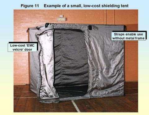
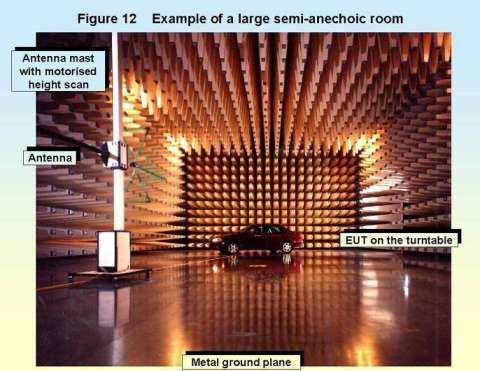
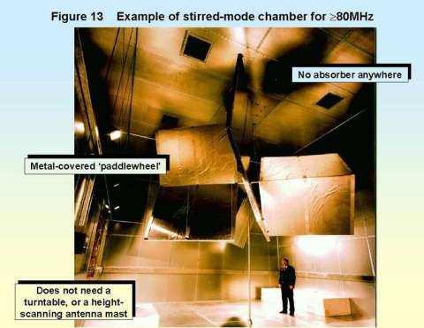
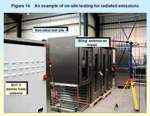
 EMC Measurements Test Site Locations Open Area (Field) Test Site Obstruction Free Trees, vegetation, buildings etc. Chamber or Screened Room Smaller Equipments Attenuate external fields (about 100dB) External
Caution - leakage currents! Leakage currents in fault-current protected environments
 Caution - leakage currents! Leakage currents in fault-current protected environments Herbert Blum Product Manager EMC > General situation > Leakage current vs. fault current > Leakage currents from frequency
Design of EMI Filters for DC-DC converter
 Design of EMI Filters for DC-DC converter J. L. Kotny*, T. Duquesne**, N. Idir** Univ. Lille Nord de France, F-59000 Lille, France * USTL, F-59650 Villeneuve d Ascq, France ** USTL, L2EP, F-59650 Villeneuve
About the High-Frequency Interferences produced in Systems including PWM and AC Motors
 About the High-Frequency Interferences produced in Systems including PWM and AC Motors ELEONORA DARIE Electrotechnical Department Technical University of Civil Engineering B-dul Pache Protopopescu 66,
Advanced Test Equipment Rentals ATEC (2832)
") Established 1981 Advanced Test Equipment Rentals www.atecorp.com 800-404-ATEC (2832) R3000 EMI TEST RECEIVERS Fully IF digital EMI Receivers family for measurement of electromagnetic interference from
Established 1981 Advanced Test Equipment Rentals www.atecorp.com 800-404-ATEC (2832) R3000 EMI TEST RECEIVERS Fully IF digital EMI Receivers family for measurement of electromagnetic interference from
Design and Simulation of PFC Circuit for AC/DC Converter Based on PWM Boost Regulator
 International Journal of Automation and Power Engineering, 2012, 1: 124-128 - 124 - Published Online August 2012 www.ijape.org Design and Simulation of PFC Circuit for AC/DC Converter Based on PWM Boost
CHAPTER-6 MEASUREMENT OF SHAFT VOLTAGE AND BEARING CURRENT IN 2, 3 AND 5-LEVEL INVERTER FED INDUCTION MOTOR DRIVE
 12 CHAPTER-6 MEASUREMENT OF SHAFT VOLTAGE AND BEARING CURRENT IN 2, 3 AND 5-LEVEL INVERTER FED INDUCTION MOTOR DRIVE 6.1. INTRODUCTION Though the research work is concerned with the measurement of CM voltage,
Mr. DILIP J. Final Year Mtech Student Dept of EEE The Oxford College of Engineering, Bangalore
 International Journal of Research Studies in Electrical and Electronics Engineering (IJRSEEE) Volume 1, Issue 1, June 2015, PP 9-17 www.arcjournals.org The Proposed Research Technology and Data Implementation
Grounding Effect on Common Mode Interference of Coal Mine Inverter
 202 International Conference on Computer Technology and Science (ICCTS202) IPCSIT vol. 47 (202) (202) IACSIT Press, Singapore Grounding Effect on Common Mode Interference of Coal Mine Inverter SUN Ji-ping,
Research Paper ELECTROMAGNETIC INTERFERENCE REDUCTION IN CUK CONVERTER USING MODIFIED PWM TECHNIQUES
 Research Paper ELECTROMAGNETIC INTERFERENCE REDUCTION IN CUK CONVERTER USING MODIFIED PWM TECHNIQUES *1 Dr. Sivaraman P and 2 Prem P Address for Correspondence Department of Electrical and Electronics
Coupling modes. Véronique Beauvois, Ir Copyright 2015 Véronique Beauvois, ULg
 Coupling modes Véronique Beauvois, Ir. 2015-2016 General problem in EMC = a trilogy Parameters Amplitude Spectrum Source (disturbing) propagation Coupling modes Victim (disturbed) lightning electrostatic
Parallel Resonance Effect on Conducted Cm Current in Ac/Dc Power Supply
 International Journal of Engineering Science Invention ISSN (Online): 2319 6734, ISSN (Print): 2319 6726 Volume 2 Issue 6 ǁ June. 2013 ǁ PP.31-35 Parallel Resonance Effect on Conducted Cm Current in Ac/Dc
Space Vector Modulation Techniques for Common mode Voltage Elimination in the Threelevel Voltage Source Inverter
 Space Vector Modulation Techniques for Common mode Voltage Elimination in the Threelevel Voltage Source Inverter Piotr Lezynski University of Zielona Gora p.lezynski@iee.uz.zgora.pl Abstract- The low common
Solution of EMI Problems from Operation of Variable-Frequency Drives
 Pacific Gas and Electric Company Solution of EMI Problems from Operation of Variable-Frequency Drives Background Abrupt voltage transitions on the output terminals of a variable-frequency drive (VFD) are
Differential-Mode Emissions
 Differential-Mode Emissions In Fig. 13-5, the primary purpose of the capacitor C F, however, is to filter the full-wave rectified ac line voltage. The filter capacitor is therefore a large-value, high-voltage
Conventional Paper-II-2011 Part-1A
 Conventional Paper-II-2011 Part-1A 1(a) (b) (c) (d) (e) (f) (g) (h) The purpose of providing dummy coils in the armature of a DC machine is to: (A) Increase voltage induced (B) Decrease the armature resistance
CHAPTER 4 MEASUREMENT OF NOISE SOURCE IMPEDANCE
 69 CHAPTER 4 MEASUREMENT OF NOISE SOURCE IMPEDANCE 4.1 INTRODUCTION EMI filter performance depends on the noise source impedance of the circuit and the noise load impedance at the test site. The noise
TEST REPORT... 1 CONTENT...
 CONTENT TEST REPORT... 1 CONTENT... 2 1 TEST RESULTS SUMMARY... 3 2 EMF RESULTS CONCLUSION... 4 3 LABORATORY MEASUREMENTS... 5 4 EMI TEST... 6 4.1 DISTURBANCE VOLTAGE ON MAINS TERMINALS ( KHZ- MHZ)...
A NEW APPROACH TO ANALYSE AND REDUCTION OF RADIO FREQUENCY CONDUCTED EMISSION DUE TO P.W.M IN A BUCK CONVERTER
 A NEW APPROACH TO ANALYSE AND REDUCTION OF RADIO FREQUENCY CONDUCTED EMISSION DUE TO P.W.M IN A BUCK CONVERTER A. FARHADI IRAN Electromagnetic Interference (EMI) which is also called as Radio Frequency
External Drive Hardware
 US1086e_External Drive Hardware, 08/2010 External Drive Hardware Selection and Application Answers Answers to external hardware questions A soup to nuts list of questions with installation / application
Application of Random PWM Technique for Reducing EMI
 International Research Journal of Applied and Basic Sciences 2013 Available online at www.irjabs.com ISSN 2251-838X / Vol, 6 (9): 1237-1242 Science Explorer Publications Application of Random PWM Technique
Conducted EMI Simulation of Switched Mode Power Supply
 Conducted EMI Simulation of Switched Mode Power Supply Hongyu Li #1, David Pommerenke #2, Weifeng Pan #3, Shuai Xu *4, Huasheng Ren *5, Fantao Meng *6, Xinghai Zhang *7 # EMC Laboratory, Missouri University
THE USE OF PROTECTIVE EARTH AS A DISTRIBUTOR OF FIELDS AND RADIATION
 THE USE OF PROTECTIVE EARTH AS A DISTRIBUTOR OF FIELDS AND (1) MARTIN LUNDMARK M.Sc M.Sc Martin.Lundmark@tt.luth.se (1) ANDERS LARSSON B.Sc Anders.Larsson@tt.luth.se (1) JANOLOF HAGELBERG Janolof.Hagelberg@tt.luth.se
Electromagnetic Compatibility and Better Harmonic Performance with Seven Level CHB Converter Based PV-Battery Hybrid System
 Electromagnetic Compatibility and Better Harmonic Performance with Seven Level CHB Converter Based PV-Battery Hybrid System A. S. S. Veerendra Babu 1, G. Kiran Kumar 2 1 M.Tech Scholar, Department of EEE,
A Novel H Bridge based Active inductor as DC link Reactor for ASD Systems
 A Novel H Bridge based Active inductor as DC link Reactor for ASD Systems K Siva Shankar, J SambasivaRao Abstract- Power converters for mobile devices and consumer electronics have become extremely lightweight
Simulation and Comparision of Back To Back System using Bidirectional Isolated DC-DC Converter with Active Energy Storage
 International Journal of Electrical Engineering. ISSN 0974-2158 Volume 5, Number 3 (2012), pp. 231-238 International Research Publication House http://www.irphouse.com Simulation and Comparision of Back
EMI Filter Design of a Three-Phase Buck-Type PWM Rectifier for Aircraft Applications.
 TÉCNICAS DE CONVERSIÓN DE POTENCIA 85 EMI Filter Design of a Three-Phase Buck-Type PWM Rectifier for Aircraft Applications. Marcelo Silva, Nico Hensgens, Jesús Oliver, Pedro Alou, Óscar García, and José
A Switched Boost Inverter Fed Three Phase Induction Motor Drive
 A Switched Boost Inverter Fed Three Phase Induction Motor Drive 1 Riya Elizabeth Jose, 2 Maheswaran K. 1 P.G. student, 2 Assistant Professor 1 Department of Electrical and Electronics engineering, 1 Nehru
Comparison between Conventional and Modified Cascaded H-Bridge Multilevel Inverter-Fed Drive
 Comparison between Conventional and Modified Cascaded H-Bridge Multilevel Inverter-Fed Drive Gleena Varghese 1, Tissa Tom 2, Jithin K Sajeev 3 PG Student, Dept. of Electrical and Electronics Engg., St.Joseph
Bearing Currents and Shaft Voltage Reduction in Dual-Inverter-Fed Open-End Winding Induction Motor With CMV PWM Methods Employing PID
 Bearing Currents and Shaft Voltage Reduction in Dual-Inverter-Fed Open-End Winding Induction Motor With CMV PWM Methods Employing PID T.Rakesh 1, K.Suresh 2 1 PG Scholar (PS), Nalanda Institute of Engineering
Bearing Currents and Shaft Voltage Reduction in Dual-Inverter-Fed Open-End Winding Induction Motor With CMV PWM Methods Employing PID
 Bearing Currents and Shaft Voltage Reduction in Dual-Inverter-Fed Open-End Winding Induction Motor With CMV PWM Methods Employing PID I.Rajya Lakshmi 1 P.V Subba Rao 2 1 PG Scholar (EEE), RK College of
About Measurement Uncertainty of Conducted Emissions Generated by a Variable Speed Drive
 About Measurement Uncertainty of Conducted Emissions Generated by a Variable Speed Drive Daniele Gallo 1, Carmine Landi, 1 Nicola Pasquino, 2 Vincenzo Ruotolo, 2 1 Dept. of Information Engineering, Second
QPI-AN1 GENERAL APPLICATION NOTE QPI FAMILY BUS SUPPLY QPI CONVERTER
 QPI-AN1 GENERAL APPLICATION NOTE QPI FAMILY EMI control is a complex design task that is highly dependent on many design elements. Like passive filters, active filters for conducted noise require careful
PQ for Industrial Benchmarking with various methods to improve. Tushar Mogre.
 General PQ: Power Quality has multiple issues involved. Thus, need to have some benchmarking standards. Very little is spoken about the LT supply installation within an industry. There is need to understand
DRIVEN ASYNCHRONOUS MOTORS
 STUDY OF ELECTROMAGNETIC ETIC INTERFERENCE IN INVERTER DRIVEN ASYNCHRONOUS MOTORS STUDY OF ELECTROMAGNETIC ETIC INTERFERENCE IN INVERTER DRIVEN ASYNCHRONOUS MOTORS Eng. Ioan ŢILEA PhD-student 1, Prof.
T + T /13/$ IEEE 236. the inverter s input impedances on the attenuation of a firstorder
 Emulation of Conducted Emissions of an Automotive Inverter for Filter Development in HV Networks M. Reuter *, T. Friedl, S. Tenbohlen, W. Köhler Institute of Power Transmission and High Voltage Technology
Specification for Conducted Emission Test
 1 of 10 1. EMI Receiver Frequency range 9kHz 7.0 GHz Measurement time per frequency 10 µs to 100 s time sweep, span = 0 Hz - 1 µs to 16000 s Sweep time in steps of 5 % frequency sweep, span 10 Hz - 2.5
Design & Implementation of a practical EMI filter for high frequencyhigh power dc-dc converter according to MIL-STD-461E
 Design & Implementation of a practical EMI filter for high frequencyhigh power dc-dc converter according to MIL-STD-461E Ashish Tyagi 1, Dr. Jayapal R. 2, Dr. S. K. Venkatesh 3, Anand Singh 4 1 Ashish
EMI Filter Design Example. This is a very small 1 hour session based on our 2 Day EMI Filter Design Workshop
 Biricha Digital Power Ltd Parkway Dr Reading RG4 6XG UK April - 208 EMI Filter Design Example This is a very small hour session based on our 2 Day EMI Filter Design Workshop Dr Ali Shirsavar Biricha Digital
A Modified Single Phase Inverter Topology with Active Common Mode Voltage Cancellation
 A Modified Single Phase Inverter Topology with Active Common Mode Voltage Cancellation A. Rao *, T.A. Lipo University of Wisconsin Madison 1415, Engineering Drive Madison, WI 53706, USA * Email: arao@cae.wisc.edu
Introduction to Electromagnetic Compatibility
 Introduction to Electromagnetic Compatibility Second Edition CLAYTON R. PAUL Department of Electrical and Computer Engineering, School of Engineering, Mercer University, Macon, Georgia and Emeritus Professor
Electromagnetic Compatibility of Power Converters
 Published by CERN in the Proceedings of the CAS-CERN Accelerator School: Power Converters, Baden, Switzerland, 7 14 May 2014, edited by R. Bailey, CERN-2015-003 (CERN, Geneva, 2015) Electromagnetic Compatibility
ANALYSIS OF EFFECTS OF VECTOR CONTROL ON TOTAL CURRENT HARMONIC DISTORTION OF ADJUSTABLE SPEED AC DRIVE
 ANALYSIS OF EFFECTS OF VECTOR CONTROL ON TOTAL CURRENT HARMONIC DISTORTION OF ADJUSTABLE SPEED AC DRIVE KARTIK TAMVADA Department of E.E.E, V.S.Lakshmi Engineering College for Women, Kakinada, Andhra Pradesh,
CHAPTER 3 SINGLE SOURCE MULTILEVEL INVERTER
 42 CHAPTER 3 SINGLE SOURCE MULTILEVEL INVERTER 3.1 INTRODUCTION The concept of multilevel inverter control has opened a new avenue that induction motors can be controlled to achieve dynamic performance
Transformerless Grid-Connected Inverters for Photovoltaic Modules: A Review
 International Journal of Engineering and Technical Research (IJETR) ISSN: 2321-869, Volume 3, Issue 4, April 215 Transformerless Grid-Connected Inverters for Photovoltaic Modules: A Review Sushant S. Paymal,
APPLICATION NOTE. Measurement of the interference voltage on DC/DC switching regulators. 1. Challenge
 1. Challenge Developers of switched-mode power supplies face the challenge of developing their circuit to be EMCcompliant. Conducted interference particularly occurs in the input circuit whereby other
Active damping of output LC filter resonance for vector controlled VSI- fed AC motor drive
 The International Journal Of Engineering And Science (IJES) Volume 3 Issue 6 Pages 50-56 2014 ISSN (e): 2319 1813 ISSN (p): 2319 1805 Active damping of output LC filter resonance for vector controlled
Ileana-Diana Nicolae ICMET CRAIOVA UNIVERSITY OF CRAIOVA MAIN BUILDING FACULTY OF ELECTROTECHNICS
 The Designing, Realization and Testing of a Network Filter used to Reduce Electromagnetic Disturbances and to Improve the EMI for Static Switching Equipment Petre-Marian Nicolae Ileana-Diana Nicolae George
Vacon Baltic Days Tallinn, Estonia
 Vacon Baltic Days 22.-23.9.2011 Tallinn, Estonia Vacon Technology Yrjö Karvonen Technical Account Manager Frequency converter Why to use Applications Energy saving Easy to control (ma, V, digital I/O,
Understanding Input Harmonics and Techniques to Mitigate Them
 Understanding Input Harmonics and Techniques to Mitigate Them Mahesh M. Swamy Yaskawa Electric America YASKAWA Page. 1 Organization Introduction Why FDs Generate Harmonics? Harmonic Limit Calculations
Keysight Technologies Essential Capabilities of EMI Receivers. Application Note
 Keysight Technologies Essential Capabilities of EMI Receivers Application Note Contents Introduction... 3 CISPR 16-1-1 Compliance... 3 MIL-STD-461 Compliance... 4 Important features not required by CISPR
CHAPTER 4 MODIFIED H- BRIDGE MULTILEVEL INVERTER USING MPD-SPWM TECHNIQUE
 58 CHAPTER 4 MODIFIED H- BRIDGE MULTILEVEL INVERTER USING MPD-SPWM TECHNIQUE 4.1 INTRODUCTION Conventional voltage source inverter requires high switching frequency PWM technique to obtain a quality output
Harmonic control devices. ECE 528 Understanding Power Quality
 ECE 528 Understanding Power Quality http://www.ece.uidaho.edu/ee/power/ece528/ Paul Ortmann portmann@uidaho.edu 208-733-7972 (voice) Lecture 12 1 Today Harmonic control devices In-line reactors (chokes)
Chapter 30 Inductance, Electromagnetic. Copyright 2009 Pearson Education, Inc.
 Chapter 30 Inductance, Electromagnetic Oscillations, and AC Circuits 30-7 AC Circuits with AC Source Resistors, capacitors, and inductors have different phase relationships between current and voltage
Measurement and reduction of EMI radiated by a PWM inverter-fed AC motor drive system
 Engineering Electrical Engineering fields Okayama University Year 1997 Measurement and reduction of EMI radiated by a PWM inverter-fed AC motor drive system Satoshi Ogasawara Okayama University Hirofumi
Techniques to reduce electromagnetic noise produced by wired electronic devices
 Rok / Year: Svazek / Volume: Číslo / Number: Jazyk / Language 2016 18 5 EN Techniques to reduce electromagnetic noise produced by wired electronic devices - Tomáš Chvátal xchvat02@stud.feec.vutbr.cz Faculty
Lecture Note. DC-AC PWM Inverters. Prepared by Dr. Oday A Ahmed Website: https://odayahmeduot.wordpress.com
 Lecture Note 10 DC-AC PWM Inverters Prepared by Dr. Oday A Ahmed Website: https://odayahmeduot.wordpress.com Email: 30205@uotechnology.edu.iq Scan QR DC-AC PWM Inverters Inverters are AC converters used
PERFORMANCE ANALYSIS OF SOLAR POWER GENERATION SYSTEM WITH A SEVEN-LEVEL INVERTER SUDHEER KUMAR Y, PG STUDENT CHANDRA KIRAN S, ASSISTANT PROFESSOR
 PERFORMANCE ANALYSIS OF SOLAR POWER GENERATION SYSTEM WITH A SEVEN-LEVEL INVERTER SUDHEER KUMAR Y, PG STUDENT CHANDRA KIRAN S, ASSISTANT PROFESSOR KV SUBBA REDDY INSTITUTE OF TECHNOLOGY, KURNOOL Abstract:
A Comparison Between MIL-STD and Commercial EMC Requirements Part 2. By Vincent W. Greb President, EMC Integrity, Inc.
 A Comparison Between MIL-STD and Commercial EMC Requirements Part 2 By Vincent W. Greb President, EMC Integrity, Inc. OVERVIEW Compare and contrast military (i.e., MIL-STD) and commercial EMC immunity
Electromagnetic interference at the mains ports of an equipment
 Electromagnetic interference at the mains ports of an equipment Mircea Ion Buzdugan, Horia Bălan, Emil E. Simion, Tudor Ion Buzdugan Technical University from Cluj-Napoca, 15, Constantin Daicoviciu street,
Minimizing Input Filter Requirements In Military Power Supply Designs
 Keywords Venable, frequency response analyzer, MIL-STD-461, input filter design, open loop gain, voltage feedback loop, AC-DC, transfer function, feedback control loop, maximize attenuation output, impedance,
Filter Considerations for the IBC
 APPLICATION NOTE AN:202 Filter Considerations for the IBC Mike DeGaetano Application Engineering Contents Page Introduction 1 IBC Attributes 1 Input Filtering Considerations 2 Damping and Converter Bandwidth
Hybrid Modulation Technique for Cascaded Multilevel Inverter for High Power and High Quality Applications in Renewable Energy Systems
 International Journal of Electronic and Electrical Engineering. ISSN 0974-2174 Volume 5, Number 1 (2012), pp. 59-68 International Research Publication House http://www.irphouse.com Hybrid Modulation Technique
Analysis of Harmonic Distortion in Non-linear Loads
 Analysis of Harmonic Distortion in Non-linear Loads Anne Ko Department of Electrical Power Engineering Mandalay Technological University, Mandalay, Myanmar.Phone:+95-09-2225761 anneko101082@gmail.com Wunna
Test and Measurement for EMC
 Test and Measurement for EMC Bogdan Adamczyk, Ph.D., in.c.e. Professor of Engineering Director of the Electromagnetic Compatibility Center Grand Valley State University, Michigan, USA Ottawa, Canada July
Applications & Cases. EPCOS AG A TDK Group Company Edition
 Applications & Cases Reference Firs EPCOS AG A TDK Group Company Edition 2018 www.epcos.com 1 / 11 egrated solution for inverters to be used in e-mobility powertrains and industrial applications. The design
The Value of Pre-Selection in EMC Testing. Scott Niemiec Application Engineer
 The Value of Pre-Selection in EMC Testing Scott Niemiec Application Engineer Video Demonstrating Benefit of Pre-selection 400MHz -1GHz Sweep with RBW = 120kHz Yellow: w/ preselection Green: w/o pre-selection
LISN UP Application Note
 LISN UP Application Note What is the LISN UP? The LISN UP is a passive device that enables the EMC Engineer to easily distinguish between differential mode noise and common mode noise. This will enable
[Mahagaonkar*, 4.(8): August, 2015] ISSN: (I2OR), Publication Impact Factor: 3.785
![[Mahagaonkar*, 4.(8): August, 2015] ISSN: (I2OR), Publication Impact Factor: 3.785](/thumbs/79/80126240.jpg "[Mahagaonkar*, 4.(8): August, 2015] ISSN: (I2OR), Publication Impact Factor: 3.785") IJESRT INTERNATIONAL JOURNAL OF ENGINEERING SCIENCES & RESEARCH TECHNOLOGY POWER QUALITY IMPROVEMENT OF GRID CONNECTED WIND ENERGY SYSTEM BY USING STATCOM Mr.Mukund S. Mahagaonkar*, Prof.D.S.Chavan * M.Tech
IJESRT INTERNATIONAL JOURNAL OF ENGINEERING SCIENCES & RESEARCH TECHNOLOGY POWER QUALITY IMPROVEMENT OF GRID CONNECTED WIND ENERGY SYSTEM BY USING STATCOM Mr.Mukund S. Mahagaonkar*, Prof.D.S.Chavan * M.Tech
Simulation of Three Phase Cascaded H Bridge Inverter for Power Conditioning Using Solar Photovoltaic System
 Simulation of Three Phase Cascaded H Bridge Inverter for Power Conditioning Using Solar Photovoltaic System 1 G.Balasundaram, 2 Dr.S.Arumugam, 3 C.Dinakaran 1 Research Scholar - Department of EEE, St.
TDA Power Factor Controller. IC for High Power Factor and Active Harmonic Filtering
 Power Factor Controller IC for High Power Factor and Active Harmonic Filtering TDA 4817 Advance Information Bipolar IC Features IC for sinusoidal line-current consumption Power factor approaching 1 Controls
Harmonic Reduction in Induction Motor: Multilevel Inverter
 International Journal of Multidisciplinary and Current Research Research Article ISSN: 2321-3124 Available at: http://ijmcr.com Harmonic Reduction in Induction Motor: Multilevel Inverter D. Suganyadevi,
via cable Route of signal interferences Shielding against radiation
 1. Introduction In the vicinity of electronics and control systems, there is often high powered equipment and cabling. In these situations it is possible that electronic circuits can be affected by these
Speed Control of Induction Motor using Multilevel Inverter
 Speed Control of Induction Motor using Multilevel Inverter 1 Arya Shibu, 2 Haritha S, 3 Renu Rajan 1, 2, 3 Amrita School of Engineering, EEE Department, Amritapuri, Kollam, India Abstract: Multilevel converters
Forward with Active Clamp for space applications: clamp capacitor, dynamic specifications and EMI filter impact on the power stage design
 Forward with Active Clamp for space applications: clamp capacitor, dynamic specifications and EMI filter impact on the power stage design G. Salinas, B. Stevanović, P. Alou, J. A. Oliver, M. Vasić, J.
Multilevel Inverter Based Statcom For Power System Load Balancing System
 IOSR Journal of Electronics and Communication Engineering (IOSR-JECE) e-issn: 2278-2834,p- ISSN: 2278-8735 PP 36-43 www.iosrjournals.org Multilevel Inverter Based Statcom For Power System Load Balancing
EVALUATION OF VARIOUS UNIPOLAR MULTICARRIER PWM STRATEGIES FOR FIVE LEVEL FLYING CAPACITOR INVERTER
 Journal of Engineering Science and Technology Vol. 7, No. 3 (2012) 379-392 School of Engineering, Taylor s University EVALUATION OF VARIOUS UNIPOLAR MULTICARRIER PWM STRATEGIES FOR FIVE LEVEL FLYING CAPACITOR
PC Krause and Associates, Inc.
 Common-mode challenges in high-frequency switching converters 14 NOV 2016 Nicholas Benavides, Ph.D. (Sr. Lead Engineer) 3000 Kent Ave., Suite C1-100 West Lafayette, IN 47906 (765) 464-8997 (Office) (765)
Laboratory no. 3 FLUORESCENT LAMPS FITTINGS
 Laboratory no. 3 FLUORESCENT LAMPS FITTINGS 3.1 General information The fluorescent lamps powered at industrial frequency voltage act as nonlinear resistors, non-inertial, with a dynamic symmetric volt-ampere
Recent Approaches to Develop High Frequency Power Converters
 The 1 st Symposium on SPC (S 2 PC) 17/1/214 Recent Approaches to Develop High Frequency Power Converters Location Fireworks Much snow Tokyo Nagaoka University of Technology, Japan Prof. Jun-ichi Itoh Dr.
Multilevel Inverter with Coupled Inductors with Sine PWM Techniques
 Multilevel Inverter with Coupled Inductors with Sine PWM Techniques S.Subalakshmi 1, A.Mangaiyarkarasi 2, T.Jothi 3, S.Rajeshwari 4 Assistant Professor-I, Dept. of EEE, Prathyusha Institute of Technology
Design and Simulation of Passive Filter
 Chapter 3 Design and Simulation of Passive Filter 3.1 Introduction Passive LC filters are conventionally used to suppress the harmonic distortion in power system. In general they consist of various shunt
Reducing EMI in buck converters
 Application Note Roland van Roy AN045 January 2016 Reducing EMI in buck converters Abstract Reducing Electromagnetic interference (EMI) in switch mode power supplies can be a challenge, because of the
FFT 3010 EMI TEST RECEIVER
 FFT 3010 EMI TEST RECEIVER Fully FFT digital EMI Receiver for measurement of conducted electromagnetic interference from 9kHz to 30MHz Compact designed and manufactured compliant to CISPR 16 International
Influence of Termination Impedance on conducted Emissions in Automotive High Voltage Networks
 Influence of Termination Impedance on conducted Emissions in Automotive High Voltage Networks M. Reuter *, S. Tenbohlen, W. Koehler Institute of Power Transmission and High Voltage Technology (IEH), University
Volume I Issue VI 2012 September-2012 ISSN
 A 24-pulse STATCOM Simulation model to improve voltage sag due to starting of 1 HP Induction-Motor Mr. Ajay Kumar Bansal 1 Mr. Govind Lal Suthar 2 Mr. Rohan Sharma 3 1 Associate Professor, Department of
FAQ for SIMOREG 6RA70 and Control Module
 I DT LD CS 28 / February / 2011 FAQ for SIMOREG 6RA70 and Control Module Question: What requirements apply for line quality and what line interference can occur? Answer: Line requirements: Voltage: rated
Mitigation of Common mode Noise for PFC Boost Converter by Balancing Technique
 Mitigation of Common mode Noise for PFC Boost Converter by Balancing Technique Nasir *, Jon Cobb *Faculty of Science and Technology, Bournemouth University, Poole, UK, nasir@bournemouth.ac.uk, Faculty
Employing Reliable Protection Methods for Automotive Electronics
 Employing Reliable Protection Methods for Automotive Electronics WHITE PAPER BACKGROUND Automotive systems continue to become more sophisticated with the introduction of new, modified and improved features