External Drive Hardware
|
|
|
- Merryl Simmons
- 6 years ago
- Views:
Transcription

1 US1086e_External Drive Hardware, 08/2010 External Drive Hardware Selection and Application Answers Answers to external hardware questions A soup to nuts list of questions with installation / application sensitive answers Do I need an inverter duty motor? Do I need a dv/dt filter? Do I need a sine filter? Do I need a common mode filter? Do I need a EMI filter? Can I use a circuit breaker to protect my drive? How can I avoid motor bearing current damage? Well, that all depends! Slide 2
2 What is an inverter duty motor? Basic standard NEMA MG1 Part 31, Definite-Purpose Inverter-Fed Polyphase Motors Speed-torque capability , Basis of Rating 4 characteristic points on speed vs. torque curve Peak voltage tolerance , Voltage Spikes V peak = 3.1 x V rated (minimum) (1550 V for 500 Vac motor) Rise time = 0.1 µs (minimum) Shaft voltage and bearing currents , Shaft Voltages and Bearing Insulation Information and recommendations (no requirements) Slide 3 Why consider using an inverter duty motor? Standard motors are designed for 60 Hz operation from a sinusoidal source Reduced frequency, reduced voltage torque capabilities are not explicitly defined Extended insulation capability is not provided In some drive installations / applications overheating or insulation failure could occur Inverter duty motors are designed for variable frequency operation from a PWM inverter source Reduced frequency, reduced voltage torque capabilities are explicitly defined Extended insulation capability is provided Installation / application overheating and insulation failure are avoided by motor design Increases motor reliability and life Slide 4
3 Do I need an inverter duty motor? ABB recommends inverter duty motors for all drives Inverter duty motors are especially important when motor lead lengths are long > 20 feet for 5 Hp or less > 50 feet for 25 Hp or less > 100 feet for all higher Hp drive voltage rise/fall times are rapid typically includes all IGBT drives constant torque applications which require well defined continuous low speed torque capability dv/dt filters and sine filters can provide an alternative when existing non-inverter duty motors are present filters address peak voltage and rise/fall time issues filters do not improve speed-torque capability Slide 5 What is a dv/dt filter? dv/dt rate of change of voltage per unit time (2000 to 6500 V/µs typical) dv/dt filter physical characteristics passive device installed between drive output and motor input includes inductive, capacitive, and resistive elements series inductors carry full rated motor current dv/dt filter functional characteristics designed to pass low frequency, filter out high frequency (i.e. a low pass filter) reduces dv/dt applied to motor reduces peak voltage applied to motor (addresses voltage reflection / voltage ringing) not designed to eliminate drive switching frequency not designed to provide common mode filtering Slide 6
4 Why consider using a dv/dt filter? Advantages of installing a dv/dt filter reduces peak voltage at motor terminals reduces dv/dt at motor terminals reduces peak cable charging current Disadvantages of installing a dv/dt filter Additional cost Additional space requirement Some additional voltage drop (approximately 1.5% at rated load) Additional losses (lowers efficiency) Imposes limits on maximum operating frequency limited to motor cable lengths of approximately 1500 feet or less Slide 7 Do I need a dv/dt filter? A dv/dt filter is not needed for motor insulation protection if: inverter duty motor(s) are installed and no secondary distribution point is involved and motor cable lengths are less than 1000 feet A dv/dt filter should be installed for motor insulation protection if: only standard duty motor(s) are installed or a secondary distribution point is included that is more than 20 feet from the drive or motor cable lengths are more than 1000 feet (significant double pulsing voltage peaks are likely) See Decision Flowchart for additional details and exceptions A dv/dt filter should be installed to reduce peak cable charging current if total motor cable length exceeds hardware manual limit and total motor cable length < 1.5 x hardware manual limit Slide 8
5 What is a sine filter? sine sinusoidal waveform output sine filter physical characteristics passive device installed between drive output and motor input includes inductive, resistive, and capacitive elements series elements carry full rated motor current sine filter functional characteristics designed to pass low frequency, filter out high frequency (i.e. a low pass filter) eliminates switching dv/dt at motor eliminates peak and ringing voltage at motor (no voltage reflection / no voltage ringing) designed to eliminate drive switching frequency not designed to provide common mode filtering Slide 9 Why consider using a sine filter? Advantages of installing a sine filter eliminates peak voltage at motor terminals eliminates dv/dt at motor terminals eliminates cable charging current peaks only positive solution for motor cable lengths beyond 1500 feet Disadvantages of installing a sine filter Significant additional cost Additional space requirement Significant additional voltage drop (approximately 5% at rated load) Often necessitates inclusion of a step-up transformer to insure sufficient motor voltage Transformation ratio may necessitate a larger drive due to increased current loading Additional losses (lowers efficiency) Drive must operate in scalar mode Imposes limits on maximum operating frequency Slide 10 Recommendation: Contact ABB Application Engineering
6 Do I need a sine filter? Install a sine filter if: a dv/dt filter can t provide sufficient motor insulation protection a dv/dt filter can t sufficiently limit cable charging current See Decision Review total voltage drops carefully Flowchart for Sine filter typically has 5% drop at rated load additional details Cables typically have 3% - 5% drop at 1500 feet A custom ratio step-up transformer is often needed Verify that motor voltage starvation won t occur (full speed / full load) Typical Sine Filter Circuit Slide 11 Recommendation: Contact ABB Application Engineering Decision Flowchart for Filter Inclusion Slide 12
7 What is a common mode filter? Common mode (CM) phenomenon voltage and current components three phases (referenced in common) to equipment ground present with inverters due to unsymmetrical output switching Common mode filter physical characteristics passive device installed between drive output and motor input appears as a lossy series inductive element Adds inductance with respect to ground (not between phases) Common mode filter functional characteristics attenuates CM current to ground reduces peak voltage to ground at motor (addresses common mode voltage reflection / voltage ringing) reduces dv/dt to ground at motor doesn t impact phase to phase voltage or current reduces inverter generated EMI (relatively slight impact) Slide 13 Why consider using a common mode filter? Advantages of installing a common mode filter reduces peak voltage to ground at motor terminals reduces dv/dt to ground at motor terminals reduces peak cable charging current to ground reduces drive generated EMI reduces peak shaft voltage (bearing current issue) Disadvantages of installing a common mode filter Additional cost Additional space requirement Additional losses (lowers efficiency) Often not readily available Slide 14
 EMI is an issue even when all motor cable shielding")
8 Do I need a common mode filter? Install a common mode filter if: Peak cable charging current is an issue even after installing a dv/dt filter (alternatively increase drive size) EMI is an issue even when all motor cable shielding recommendations have been followed (a dedicated EMI filter is more effective) Attenuation of motor bearing currents is desired (other methods provide more effective results) Slide 15 What is an EMI filter? EMI ElectroMagnetic Interference Conducted and/or radiated electrical noise alternatively referenced as EMC electromagnetic compatibility EMI filter physical characteristics passive device installed between the primary power source and the drive input includes series inductance (CM) and shunt capacitive elements series elements carry full rated drive current EMI filter functional characteristics block CM high frequencies from the line pass CM high frequencies from equipment ground to the drive input provide a path for high frequency CM currents to return to the inverter DC bus from which they originate 100 khz to 5 MHz bandpass Reduces EMI in the equipment grounding system Slide 16
9 Why consider using an EMI filter? Advantages of installing an EMI filter reduces EMI in sensitive external equipment provides a well defined high frequency CM ground return path Disadvantages of installing an EMI filter Additional cost Additional space requirement Slide 17 Do I need an EMI filter? Install an EMI filter if: The EMC Directive must be met (i.e. CE system compliance is required) EMI is an installation issue even though all motor cable shielding recommendations are in place Radio reception is a problem and line side cabling is suspected as the radiating source Slide 18
10 What protection does a circuit breaker provide? Circuit breakers can protect drive input cables (overload, short circuit, ground fault) serve as a drive disconnect Circuit breakers can not protect drive semiconductors (diodes, IGBTs) limit drive short circuit currents to a safe level limit drive I 2 t fault energy to a safe level guarantee that drive equipment will not rupture guarantee that a drive internal fault won t lead to a fire Slide 19 What protection do fuses provide? Fuses (as specified in ABB product manuals) can limit drive short circuit current to a safe level limit drive I 2 t fault energy to a safe level guarantee that drive equipment will not rupture guarantee that a drive internal fault won t lead to a fire protect drive input cables (overload, short circuit, ground fault) if properly coordinated by the installer Fuses (as specified in ABB product manuals) can not protect drive semiconductors (diodes, IGBTs) serve as a drive disconnect Slide 20
11 Can I use a circuit breaker to provide drive protection? In general circuit breakers can not be used to provide drive protection Exception: Drives installed on networks with low available short circuit current may be sufficiently protected by a fast acting circuit breaker However, confirming protection is complex and requires complete knowledge of both the network and the drive equipment ABB s recommendation is to provide drive protection utilizing the fuses as specified in our product literature Slide 21 What are high frequency motor bearing currents? High frequency motor bearing currents are PWM drive sourced, capacitively induced, discharge currents that may damage motor bearings if of sufficient magnitude These currents may occur due to three different circuit actions which can occur individually or in combination High Frequency Circulating (motor) High Frequency Capacitive Coupling (motor or driven load) High Frequency Frame Voltage (Shaft Grounding) (motor or driven load) Equivalent circuit diagrams follow Slide 22
12 High Frequency Circulating Inverter Motor Z C M Z CG M R MB R MB V ZS C SF C MB Z MBNL C MB Z MBNL Z MAG Normally only occurs in larger motors ( 100 hp) Slide 23 High Frequency Capacitive Coupling Inverter Motor Driven Machine Z C C SR R SFT Z CG M R MB R DMB V ZS C SF C RF C MB Z MBNL C DMB Z DMBNL Z MAG Z DMG Most prominent in smaller motors ( 20 hp) Slide 24
13 High Frequency Frame Voltage (Shaft Grounding) Inverter Motor Driven Machine Z C C SR R SFT Z CG M R MB R DMB V ZS C SF C RF C MB Z MBNL C DMB Z DMBNL Z MAG Z DMG Can only occur in applications where the motor shaft is grounded through the driven load. Slide 25 Do I need to provide motor bearing current protection? It is impractical to predict whether high frequency bearing currents will be a problem at a particular site due to the number of application variables involved motor size motor cable grounding driven load grounding motor bearing design motor air gap design motor magnetic symmetry bearing loading load speed variability If it is economically feasible to address high frequency bearing current issues proactively (i.e. insurance) utilize the two charts following to determine recommended actions Slide 26
14 Preventing Motor Bearing Currents Preventative Measure - Motor Bearing Current Type Grounding Brush Armored / Shielded Cable Single Insulated Bearing Double Insulated Bearing Common Mode Choke Insulated Drive Coupling A. High Frequency Circulating S S R B. High Frequency CapacitiveCoupling S S R C. High Frequency Frame Voltage (Shaft Grounding) S R S R S S = Solves R = Reduces Recommended Solution Slide 27 Note: Grounding brush and insulated bearing must be on opposite shaft ends. Preventing Driven Load Bearing Currents Preventative Measure - Driven Load Bearing Current Type Grounding Brush Armored / Shielded Cable Single Insulated Bearing Double Insulated Bearing Common Mode Choke Insulated Drive Coupling B. High Frequency CapacitiveCoupling R S C. High Frequency Frame Voltage (Shaft Grounding) R R S R S S = Solves R = Reduces Recommended Solution Slide 28

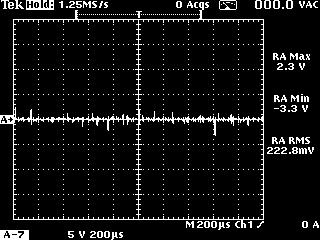

15 Grounding Device Effectiveness Before Grounding Device After Grounding Device Slide 29
MTE training MTE Corporation
 1 MTE Corporation Improving the Performance and Reliability of Power Electronic Systems 2 MTE solutions to Long lead dive applications Protection of motors drive cables and Variable frequency inverters
P2 Power Solutions Pvt. Ltd. P2 Power Magnetics. Quality Power within your Reach. An ISO 9001:2008 Company
 P2 Power Solutions Pvt. Ltd. An ISO 9001:2008 Company Quality Power within your Reach P2 Power Magnetics P2 Power Solutions Pvt. Ltd. P2 Power Solutions Pvt. Ltd. provides EMC and power quality solutions,
Application Note. Motor Bearing Current Phenomenon. Rev: Doc#: AN.AFD.17 Yaskawa Electric America, Inc August 7, /9
 Application Note Application Note Motor Bearing Current Phenomenon Rev: 08-08 Doc#: AN.AFD.17 Yaskawa Electric America, Inc. 2008 www.yaskawa.com August 7, 2008 1/9 INTRODUCTION Since the introduction
COOLTUBE Radiated Emissions Absorber
 COOLTUBE Radiated Emissions Absorber Radiated Emissions Solution from MH&W International Corp. Radiated Emissions In VFD Motor Systems 1. Defining the problem 2. Solutions 2 What is EMI? What Are Emissions?
Solution of EMI Problems from Operation of Variable-Frequency Drives
 Pacific Gas and Electric Company Solution of EMI Problems from Operation of Variable-Frequency Drives Background Abrupt voltage transitions on the output terminals of a variable-frequency drive (VFD) are
vacon 100 industrial vacon 100 flow vacon 100 hvac vacon 100 x ac drives du/dt filter technical guide
 vacon 100 industrial vacon 100 flow vacon 100 hvac vacon 100 x ac drives du/dt filter technical guide vacon 1 TABLE OF CONTENTS Document code: DPD01929A Date: 12.1.2017 1. Introduction... 2 1.1 Intended
Modeling of Conduction EMI Noise and Technology for Noise Reduction
 Modeling of Conduction EMI Noise and Technology for Noise Reduction Shuangching Chen Taku Takaku Seiki Igarashi 1. Introduction With the recent advances in high-speed power se miconductor devices, the
SWF DV/DT Solutions Sinewave Filters. N52 W13670 NORTHPARK DR. MENOMONEE FALLS, WI P. (262) F. (262)
 F. (262)") SWF DV/DT Solutions Sinewave Filters N52 W13670 NORTHPARK DR. MENOMONEE FALLS, WI 53051 P. (262) 754-3883 F. (262) 754-3993 www.apqpower.com Does your application use variable frequency drives for improved
SWF DV/DT Solutions Sinewave Filters N52 W13670 NORTHPARK DR. MENOMONEE FALLS, WI 53051 P. (262) 754-3883 F. (262) 754-3993 www.apqpower.com Does your application use variable frequency drives for improved
Product Application Note
 Application Note Product Application Note Motor Bearing urrent Phenomenon and 3-Level Inverter Technology Applicable Product: G7 Rev: 05-06 G7 three-level output waveform onventional two-level output waveform
The Reflective Wave Phenomena
 Application Note The Reflective Wave Phenomena Rev2.doc The Reflective Wave Phenomena Note to Specifiers This application note contains Cutler-Hammer s recommendations for the application of filters for
Measurement and Analysis for Switchmode Power Design
 Measurement and Analysis for Switchmode Power Design Switched Mode Power Supply Measurements AC Input Power measurements Safe operating area Harmonics and compliance Efficiency Switching Transistor Losses
SIMULATION of EMC PERFORMANCE of GRID CONNECTED PV INVERTERS
 SIMULATION of EMC PERFORMANCE of GRID CONNECTED PV INVERTERS Qin Jiang School of Communications & Informatics Victoria University P.O. Box 14428, Melbourne City MC 8001 Australia Email: jq@sci.vu.edu.au
Technical White Paper
 Technical White Paper Increased Reports of Bearing Damage in AC Motors Operating from Modern PWM VFD's Repair shops and motor manufacturers are seeing an increased number of instances where bearings and
MODELLING AND SIMULATION OF DIODE CLAMP MULTILEVEL INVERTER FED THREE PHASE INDUCTION MOTOR FOR CMV ANALYSIS USING FILTER
 MODELLING AND SIMULATION OF DIODE CLAMP MULTILEVEL INVERTER FED THREE PHASE INDUCTION MOTOR FOR CMV ANALYSIS USING FILTER Akash A. Chandekar 1, R.K.Dhatrak 2 Dr.Z.J..Khan 3 M.Tech Student, Department of
NJWA - Harmonics and Drives Proper System Design
 Session Goals Larry Stanley, Sr. Regional Business Development Engineer, Water Segment Matthew LaRue, ABB Drives Product Manager Philadelphia District, Baldor of Philadelphia NJWA - Harmonics and Drives
Selected Problems of Induction Motor Drives with Voltage Inverter and Inverter Output Filters
 9 Selected Problems of Induction Motor Drives with Voltage Inverter and Inverter Output Filters Drives and Filters Overview. Fast switching of power devices in an inverter causes high dv/dt at the rising
Application Note. Applicable Product: AC Drives
 Application Note Application Note Guidelines For The Use Of 400-600 Volt AC Drives In Medium Voltage Applications Applicable Product: AC Drives 4kV Step-down Transformer AC Drive 400-600V Output Filter
Power Quality Solutions
 Power Quality Solutions What is Power Quality? For electrical systems to function in their intended manner without significant loss of performance or life, they require a supply of electricity that is
CoolBLUE Inductive Absorbers NaLA Noise Line Absorbers
 CoolBLUE Inductive Absorbers NaLA Noise Line Absorbers Motor Bearing Solution from MH&W International Corp. http://www.coolblue-mhw.com Variable Frequency Motor Drive Systems 1. What is the problem 2.
Mr. DILIP J. Final Year Mtech Student Dept of EEE The Oxford College of Engineering, Bangalore
 International Journal of Research Studies in Electrical and Electronics Engineering (IJRSEEE) Volume 1, Issue 1, June 2015, PP 9-17 www.arcjournals.org The Proposed Research Technology and Data Implementation
CHAPTER 2 A SERIES PARALLEL RESONANT CONVERTER WITH OPEN LOOP CONTROL
 14 CHAPTER 2 A SERIES PARALLEL RESONANT CONVERTER WITH OPEN LOOP CONTROL 2.1 INTRODUCTION Power electronics devices have many advantages over the traditional power devices in many aspects such as converting
Power Electronics. Exercise: Circuit Feedback
 Lehrstuhl für Elektrische Antriebssysteme und Leistungselektronik Technische Universität München Prof Dr-Ing Ralph Kennel Aricsstr 21 Email: eat@eitumde Tel: +49 (0)89 289-28358 D-80333 München Internet:
Drives 101 Lesson 3. Parts of a Variable Frequency Drive (VFD)
") Drives 101 Lesson 3 Parts of a Variable Frequency Drive (VFD) This lesson covers the parts that make up the Variable Frequency Drive (VFD) and describes the basic operation of each part. Here is the basics
Drives 101 Lesson 3 Parts of a Variable Frequency Drive (VFD) This lesson covers the parts that make up the Variable Frequency Drive (VFD) and describes the basic operation of each part. Here is the basics
Motor Bearing Damage and Variable Frequency Drives: - Diagnosing the Causes, - Implementing a Cure, and - Avoiding the Pitfalls
 Motor Bearing Damage and Variable Frequency Drives: - Diagnosing the Causes, - Implementing a Cure, and - Avoiding the Pitfalls Tim Albers, Director of Product Mgt, NIDEC Motor Corporation Tim Jasina,
MINING EARTH LEAKAGE PROTECTION WITH VARIABLE SPEED DRIVES
 MINING EARTH LEAKAGE PROTECTION WITH VARIABLE SPEED DRIVES White Paper Tim Wylie, Ampcontrol s Chief Technology Officer discusses the impact of Variable Speed Drives (VSDs) on earth fault limited networks.
CHAPTER 1 INTRODUCTION
 1 CHAPTER 1 INTRODUCTION 1.1 GENERAL Induction motor drives with squirrel cage type machines have been the workhorse in industry for variable-speed applications in wide power range that covers from fractional
Understanding and Optimizing Electromagnetic Compatibility in Switchmode Power Supplies
 Understanding and Optimizing Electromagnetic Compatibility in Switchmode Power Supplies 1 Definitions EMI = Electro Magnetic Interference EMC = Electro Magnetic Compatibility (No EMI) Three Components
Drives 101 Lesson 5. Power Input Terminology for a VFD
 Drives 101 Lesson 5 Power Input Terminology for a VFD This lesson covers the terminology associated with the incoming power to a Variable Frequency Drive (VFD) and the efforts to protect both the VFD and
Bearing Currents and Shaft Voltages of an Induction Motor Under Hard and Soft Switching Inverter Excitation
 Bearing Currents and Shaft Voltages of an Induction Motor Under Hard and Soft Switching Inverter Excitation Shaotang Chen Thomas A. Lipo Electrical and Electronics Department Department of Electrical and
6 How to Programme the Frequency Converter 43
 Contents Contents 1 How to Read this Design Guide 3 Abbreviations 4 2 Safety and Conformity 5 Safety Precautions 5 CE Conformity and Labelling 5 3 Introduction to Output Filters 7 Why use Output Filters
Electromagnetic Compatibility
 Electromagnetic Compatibility Introduction to EMC International Standards Measurement Setups Emissions Applications for Switch-Mode Power Supplies Filters 1 What is EMC? A system is electromagnetic compatible
High Frequency SineWave Guardian TM Filter
 High Frequency SineWave Guardian TM Filter 380V 480V TECHNICAL REFERENCE MANUAL WARNING High Voltage! Only a qualified electrician can carry out the electrical installation of this filter. Quick Reference
2.10. Adjustable Frequency Drives. Clean Power Drives. Clean Power Drives
 .0 Volume 6 Solid-State Control CA0800007E March 05 www.eaton.com V6-T-47 .0 Adjustable Frequency Drives Overview What Are Harmonics? Take a perfect wave with a fundamental frequency of 60 Hz, which is
PC Krause and Associates, Inc.
 Common-mode challenges in high-frequency switching converters 14 NOV 2016 Nicholas Benavides, Ph.D. (Sr. Lead Engineer) 3000 Kent Ave., Suite C1-100 West Lafayette, IN 47906 (765) 464-8997 (Office) (765)
Vacon Baltic Days Tallinn, Estonia
 Vacon Baltic Days 22.-23.9.2011 Tallinn, Estonia Vacon Technology Yrjö Karvonen Technical Account Manager Frequency converter Why to use Applications Energy saving Easy to control (ma, V, digital I/O,
PCB layout guidelines. From the IGBT team at IR September 2012
 PCB layout guidelines From the IGBT team at IR September 2012 1 PCB layout and parasitics Parasitics (unwanted L, R, C) have much influence on switching waveforms and losses. The IGBT itself has its own
INTEGRATED CIRCUITS. AN120 An overview of switched-mode power supplies Dec
 INTEGRATED CIRCUITS An overview of switched-mode power supplies 1988 Dec Conceptually, three basic approaches exist for obtaining regulated DC voltage from an AC power source. These are: Shunt regulation
CHAPTER 4 MEASUREMENT OF NOISE SOURCE IMPEDANCE
 69 CHAPTER 4 MEASUREMENT OF NOISE SOURCE IMPEDANCE 4.1 INTRODUCTION EMI filter performance depends on the noise source impedance of the circuit and the noise load impedance at the test site. The noise
Thyristorised Automatic Power Factor
 Thyristorised Automatic Power Factor Correction with 7% D Tune Harmonics Suppression (Reactor/Filtering) System Power quality? In the present Low voltage (LV) industrial distribution system the power factor
Challenges of Parallel Operations
 GENLINK TM issimilar Pitch Limiter Key Features Inserts >40% impedance in neutral current circulating path Reduces neutral circulating current by >75% Adds
Subject to changes 11/2003 Page 1/7
 Main Characteristics: Zero switching. LED display. Various connection systems. Plug-in control terminal. Degree of protection IP 2. Double-insulated design. General Data: Standards / Approvals DIN EN 697--3
Economical Solutions to Meet Harmonic Distortion Limits[4]
![Economical Solutions to Meet Harmonic Distortion Limits[4]](/thumbs/84/89546554.jpg "Economical Solutions to Meet Harmonic Distortion Limits[4]") Economical Solutions to Meet Harmonic Distortion Limits[4] Abstract: The widespread adoption of variable frequency drive technology is allowing electricity to be utilized more efficiently throughout most
Economical Solutions to Meet Harmonic Distortion Limits[4] Abstract: The widespread adoption of variable frequency drive technology is allowing electricity to be utilized more efficiently throughout most
High Frequency Sinewave Guardian TM Filter
 High Frequency Sinewave Guardian TM Filter 380V 480V TECHNICAL REFERENCE MANUAL FORM: SHF-TRM-E REL. April 2015 REV. 001 2015 MTE Corporation Caution Prior to start up; confirm the drive operation mode
VARIABLE FREQUENCY DRIVE
 VARIABLE FREQUENCY DRIVE Yatindra Lohomi 1, Nishank Nama 2, Umesh Kumar 3, Nosheen aara 4, Uday Raj 5 (Assistant Professor in Department of Electrical Engineering GIET Kota2) (Department of Electrical
results at the output, disrupting safe, precise measurements.
 H Common-Mode Noise: Sources and Solutions Application Note 1043 Introduction Circuit designers often encounter the adverse effects of commonmode noise on a design. Once a common-mode problem is identified,
Electromagnetic and Radio Frequency Interference (EMI/RFI) Considerations For Nuclear Power Plant Upgrades
 Considerations For Nuclear Power Plant Upgrades") Electromagnetic and Radio Frequency Interference (EMI/RFI) Considerations For Nuclear Power Plant Upgrades November 9, 2016 Presented to: Presented by: Chad Kiger EMC Engineering Manager ckiger@ams-corp.com
Electromagnetic and Radio Frequency Interference (EMI/RFI) Considerations For Nuclear Power Plant Upgrades November 9, 2016 Presented to: Presented by: Chad Kiger EMC Engineering Manager ckiger@ams-corp.com
HARMONICS THE BASICS H A R M O N I C M I T I G A T I O N A N D D I S P L A C E M E N T P O W E R F A C T O R C O R R E C T I O N
 HARMONICS THE BASICS H A R M O N I C M I T I G A T I O N A N D D I S P L A C E M E N T P O W E R F A C T O R C O R R E C T I O N Harmonic Basics 3 rd Harmonic Fundamental 5 t1h Harmonic 7 th Harmonic Harmonic
Applications & Cases. EPCOS AG A TDK Group Company Edition
 Applications & Cases Reference Firs EPCOS AG A TDK Group Company Edition 2018 www.epcos.com 1 / 11 egrated solution for inverters to be used in e-mobility powertrains and industrial applications. The design
Saturation of Active Loop Antennas
 Saturation of Active Loop Antennas Alexander Kriz EMC and Optics Seibersdorf Laboratories 2444 Seibersdorf, Austria Abstract The EMC community is working towards shorter test distances for radiated emission
Part Five. High-Power ac Drives
 Part Five High-Power ac Drives Chapter 12 Voltage Source Inverter-Fed Drives 12.1 INTRODUCTION The voltage source inverter-fed medium-voltage (MV) drives have found wide application in industry. These
Improving Passive Filter Compensation Performance With Active Techniques
 IEEE TRANSACTIONS ON INDUSTRIAL ELECTRONICS, VOL. 50, NO. 1, FEBRUARY 2003 161 Improving Passive Filter Compensation Performance With Active Techniques Darwin Rivas, Luis Morán, Senior Member, IEEE, Juan
Prediction of Transient Transfer Functions at Cable-Transformer Interfaces
 1 Prediction of Transient Transfer Functions at Cable-Transformer Interfaces Joe Y. Zhou, Member, IEEE and Steven A. Boggs, Fellow, IEEE Joe Zhou participated in this work while completing his Ph.D. at
Harmonic Distortion and Variable Frequency Drives
 Harmonic Distortion and Variable Frequency Drives Definitions Variable Frequency Drives (VFDs); sometimes referred to as variable speed drives. Harmonic Distortion is a measure of the amount of deviation
Cable Solutions for Servo and Variable Frequency Drives (VFD)
") Cable Solutions for Servo and Variable Frequency Drives (VFD) Electric drive systems with continuous torque and speed control are widespread today. They allow an optimal adjustment of the drive with respect
Cable Solutions for Servo and Variable Frequency Drives (VFD) Electric drive systems with continuous torque and speed control are widespread today. They allow an optimal adjustment of the drive with respect
Application Note # 5438
 Application Note # 5438 Electrical Noise in Motion Control Circuits 1. Origins of Electrical Noise Electrical noise appears in an electrical circuit through one of four routes: a. Impedance (Ground Loop)
Besides the output current, what other aspects have to be considered when selecting a suitable gate driver for a certain application?
 General questions about gate drivers Index General questions about gate drivers... 1 Selection of suitable gate driver... 1 Troubleshooting of gate driver... 1 Factors that limit the max switching frequency...
Gate Drive Optimisation
 Gate Drive Optimisation 1. Background Driving of gates of MOSFET, IGBT and SiC/GaN switching devices is a fundamental requirement in power conversion. In the case of ground-referenced drives this is relatively
The Reflective Wave Phenomenon dv/dt and Reflective Wave unsuppressed causes Motor failures
 TCI s KLC & KLCUL dv/dtguard Output Filters Provide Superior Patented Protection for Motors s the technology of Pulse Width Modulated (PWM) Drives are incorporated into various applications and processes,
High Technology Control
 High Technology Control Michael Linden ABB National Drives Manager for High Technology Control Pty Ltd High Technology Control Variable Frequency Drives Variable Voltage Variable Frequency Drives Variable
Determination of EMI of PWM fed Three Phase Induction Motor. Ankur Srivastava
 Abstract International Journal of Technical Innovation in Modern Engineering & Science (IJTIMES) Impact Factor: 3.45 (SJIF-2015), e-issn: 2455-2584 Volume 3, Issue 05, May-2017 Determination of EMI of
Harmonic Mitigation for Variable Frequency Drives. HWEA Conference February 15, Kelvin J. Hurdle Rockwell Bus. Dev. Mgr.
 Harmonic Mitigation for Variable Frequency Drives HWEA Conference February 15, 2011 Kelvin J. Hurdle Rockwell Bus. Dev. Mgr. 1 OVERVIEW Linear vs. Non- Linear Load Definitions AC Drive Input Current Harmonics
Variable Frequency Drives Motor Bearing Failure Mitigation
 Variable Frequency Drives Motor Bearing Failure Mitigation Background Throughout the Commonwealth Campus various motors are controlled by VFDs and the University is seeing a rapid and high failure rate
CHAPTER 3 DC-DC CONVERTER TOPOLOGIES
 47 CHAPTER 3 DC-DC CONVERTER TOPOLOGIES 3.1 INTRODUCTION In recent decades, much research efforts are directed towards finding an isolated DC-DC converter with high volumetric power density, low electro
Application Note AN- 1094
 Application Note AN- 194 High Frequency Common Mode Analysis of Drive Systems with IRAMS Power Modules Cesare Bocchiola Table of Contents Page Section 1 : Introduction...2 Section 2 : The Conducted EMI
Single-phase Variable Frequency Switch Gear
 Single-phase Variable Frequency Switch Gear Eric Motyl, Leslie Zeman Advisor: Professor Steven Gutschlag Department of Electrical and Computer Engineering Bradley University, Peoria, IL May 13, 2016 ABSTRACT
A PRACTICAL GUIDE TO UNDERSTANDING BEARING DAMAGE RELATED TO PWM DRIVES
 A PRACTICAL GUIDE TO UNDERSTANDING BEARING DAMAGE RELATED TO PWM DRIVES Don Macdonald IEEE Member Toshiba International Corporation Abstract The performance and reliability of AC Adjustable Speed Drives
A Switched Boost Inverter Fed Three Phase Induction Motor Drive
 A Switched Boost Inverter Fed Three Phase Induction Motor Drive 1 Riya Elizabeth Jose, 2 Maheswaran K. 1 P.G. student, 2 Assistant Professor 1 Department of Electrical and Electronics engineering, 1 Nehru
Effect of Adjustable-Speed Drives on the Operation of Low-Voltage Ground-Fault Indicators
 IEEE TRANSACTIONS ON INDUSTRY APPLICATIONS, VOL. 37, NO. 5, SEPTEMBER/OCTOBER 2001 1423 Effect of Adjustable-Speed Drives on the Operation of Low-Voltage Ground-Fault Indicators Gary L. Skibinski, Barry
PIEZOELECTRIC TRANSFORMER FOR INTEGRATED MOSFET AND IGBT GATE DRIVER
 1 PIEZOELECTRIC TRANSFORMER FOR INTEGRATED MOSFET AND IGBT GATE DRIVER Prasanna kumar N. & Dileep sagar N. prasukumar@gmail.com & dileepsagar.n@gmail.com RGMCET, NANDYAL CONTENTS I. ABSTRACT -03- II. INTRODUCTION
Mixed Mode EMI Noise Level Measurement in SMPS
 American Journal of Applied Sciences 3 (5): 1824-1830, 2006 ISSN 1546-9239 2006 Science Publications Mixed Mode EMI Noise Level Measurement in SMPS 1 R.Dhanasekaran, 1 M.Rajaram and 2 S.N.Sivanandam 1
Automotive EMC. IEEE EMC Society Melbourne Chapter October 13, 2010 By Mark Steffka IEEE EMCS Distinguished Lecturer
 Automotive EMC IEEE EMC Society Melbourne Chapter October 13, 2010 By Mark Steffka IEEE EMCS Distinguished Lecturer Email: msteffka@ieee.org IEEE 1 Automotive Systems Past and Present Today s vehicles
VSD cables in. Working with. industrial & automation applications
 Cable Efficiency in Automation Connectivity Cabinet Control Working with VSD cables in industrial & automation applications Description of a VSD System A functional VSD system consists of at least three
Power supply CP-T 48/20.0 Primary switch mode power supply
 Data sheet Power supply CP-T 48/20.0 Primary switch mode power supply The CP-T range of three-phase power supply units is the youngest member of ABB s power supply family. In terms of design and functionality,
S11 Adjustable Speed Drive Engineering Specification
 PART 1 - GENERAL 1.0 Scope This specification shall cover Toshiba S11 AC Variable Frequency Drives, 6 pulse for 3- phase 200-240VAC, 380-500VAC and single phase 200V to 240VAC. 1.1 References A. National
Power supply CP-T 24/20.0 Primary switch mode power supply
 Data sheet Power supply CP-T 24/20.0 Primary switch mode power supply The CP-T range of three-phase power supply units is the youngest member of ABB s power supply family. In terms of design and functionality,
by Jim Philips, P.E. Pass Interference Ensuring the Electromagnetic Compatibility of Variable Frequency Drives
 by Jim Philips, P.E. Pass Interference Ensuring the Electromagnetic Compatibility of Variable Frequency Drives While driving along the highway, the big game is on the radio with the score tied, fourth
A Modified Single Phase Inverter Topology with Active Common Mode Voltage Cancellation
 A Modified Single Phase Inverter Topology with Active Common Mode Voltage Cancellation A. Rao *, T.A. Lipo University of Wisconsin Madison 1415, Engineering Drive Madison, WI 53706, USA * Email: arao@cae.wisc.edu
Power supply CP-T 48/5.0 Primary switch mode power supply
 Data sheet Power supply CP-T 48/5.0 Primary switch mode power supply The CP-T range of three-phase power supply units is the youngest member of ABB s power supply family. In terms of design and functionality,
CP-T range Product group picture
 Product group picture /1 ABB Catalog Electronic Products and Relays 1/1 2CDC 110 00 C09 Table of contents CP-T range Product group picture /1 Table of contents /2 Benefits and advantages / Ordering details
Ambient Conditions Storage Conditions Installation Minimum Clearances and Air Flow...2 3
 CHAPTER INSTALLATION 2 AND WIRING Contents of this Chapter... Ambient Conditions..............................2 2 Storage Conditions...............................2 2 Installation.....................................2
Conventional Single-Switch Forward Converter Design
 Maxim > Design Support > Technical Documents > Application Notes > Amplifier and Comparator Circuits > APP 3983 Maxim > Design Support > Technical Documents > Application Notes > Power-Supply Circuits
Three Phase PFC and Harmonic Mitigation Using Buck Boost Converter Topology
 Three Phase PFC and Harmonic Mitigation Using Buck Boost Converter Topology Riya Philip 1, Reshmi V 2 Department of Electrical and Electronics, Amal Jyothi College of Engineering, Koovapally, India 1,
Output Filters Design Guide. VLT AutomationDrive FC 300 VLT AQUA Drive FC 200 VLT HVAC Drive FC 100
 MAKING MODERN LIVING POSSIBLE VLT AutomationDrive FC 300 VLT AQUA Drive FC 200 VLT HVAC Drive FC 100 Contents Contents 1 How to Read this Design Guide 3 1.1.2 Abbreviations 3 2 Safety and Conformity 4
CHAPTER 3 SINGLE SOURCE MULTILEVEL INVERTER
 42 CHAPTER 3 SINGLE SOURCE MULTILEVEL INVERTER 3.1 INTRODUCTION The concept of multilevel inverter control has opened a new avenue that induction motors can be controlled to achieve dynamic performance
FGJTCFWP"KPUVKVWVG"QH"VGEJPQNQI[" FGRCTVOGPV"QH"GNGEVTKECN"GPIKPGGTKPI" VGG"246"JKIJ"XQNVCIG"GPIKPGGTKPI
 FGJTFWP"KPUKWG"QH"GEJPQNQI[" FGRTOGP"QH"GNGETKEN"GPIKPGGTKPI" GG"46"JKIJ"XQNIG"GPIKPGGTKPI Resonant Transformers: The fig. (b) shows the equivalent circuit of a high voltage testing transformer (shown
Application Note AN-3006 Optically Isolated Phase Controlling Circuit Solution
 www.fairchildsemi.com Application Note AN-3006 Optically Isolated Phase Controlling Circuit Solution Introduction Optocouplers simplify logic isolation from the ac line, power supply transformations, and
VFD Level II: Application Considerations. Jason Fahey, Vice President John Fahey, President
 VFD Level II: Application Considerations Jason Fahey, Vice President John Fahey, President Practical Items Type questions here and click send. How familiar are you with variable frequency drive applications?
Harmonic Filtering in Variable Speed Drives
 Harmonic Filtering in Variable Speed Drives Luca Dalessandro, Xiaoya Tan, Andrzej Pietkiewicz, Martin Wüthrich, Norbert Häberle Schaffner EMV AG, Nordstrasse 11, 4542 Luterbach, Switzerland luca.dalessandro@schaffner.com
Power Factor improved by Variable Speed AC Drives By Mauri Peltola, ABB Oy, Drives
 For your business and technology editors Power Factor improved by Variable Speed AC Drives By Mauri Peltola, ABB Oy, Drives The use of AC induction motors is essential for industry and utilities. AC induction
PROXIMITY SENSOR TERMINOLOGY
 Never use this desk reference for installation or operation of equipment. Refer to manual for installation and operation instructions. The following descriptions refer to the European standard EN 60947-5-2.
OUTLINE. Introduction. Introduction. Conducted Electromagnetic Interference in Smart Grids. Introduction. Introduction
 Robert Smoleński Institute of Electrical Engineering University of Zielona Gora Conducted Electromagnetic Interference in Smart Grids Introduction Currently there is lack of the strict, established definition
Amps Without HGA. Amps With HGA. Amps Without HSD Time (ms)
") Harmonic Solutions HarmonicGuard Active (HGA) Filter Save money and space: a single bus-applied HGA can correct harmonics for multiple loads Reduce current harmonic distortion to less than 5% allowing
Harmonic Solutions HarmonicGuard Active (HGA) Filter Save money and space: a single bus-applied HGA can correct harmonics for multiple loads Reduce current harmonic distortion to less than 5% allowing
GaN in Practical Applications
 in Practical Applications 1 CCM Totem Pole PFC 2 PFC: applications and topology Typical AC/DC PSU 85-265 V AC 400V DC for industrial, medical, PFC LLC 12, 24, 48V DC telecomm and server applications. PFC
NGS N01 LIMESTONE CRUSHER ELECTRICAL SPECIFICATIONS
 NGS N01 LIMESTONE CRUSHER ELECTRICAL SPECIFICATIONS PART 1 - GENERAL 1.0 Scope This specification shall cover the procurement, installation and factory startup (constant torque application of one VFD controlling
Caution - leakage currents! Leakage currents in fault-current protected environments
 Caution - leakage currents! Leakage currents in fault-current protected environments Herbert Blum Product Manager EMC > General situation > Leakage current vs. fault current > Leakage currents from frequency
CP-T range Benefits and advantages
 Benefits and advantages Characteristics Rated output voltages V, V DC Output voltage adjustable via front-face rotary potentiometer OUTPUT Adjust Rated output currents 5 A, 10 A, A, A Rated output powers
Power supply CP-T 24/10.0 Primary switch mode power supply
 Data sheet Power supply CP-T 24/10.0 Primary switch mode power supply The CP-T range of three-phase power supply units is the youngest member of ABB s power supply family. In terms of design and functionality,
22.0 Harmonics in Industrial Power Systems
 1.0 Harmonics in Industrial Power Systems Harmonic frequencies are multiples of the line (fundamental) frequency, which in North America is usually 60 Hz, while it is 50 Hz elsewhere. Figure 1 shows a
Sources of transient electromagnetic disturbance in medium voltage switchgear
 Sources of transient electromagnetic disturbance in medium voltage switchgear Dennis Burger, Stefan Tenbohlen, Wolfgang Köhler University of Stuttgart Stuttgart, Germany dennis.burger@ieh.uni-stuttgart.de
High Side MOSFET Gate Drive: The Power of Well. Implemented Pulse Transformers
 High Side MOSFET Gate Drive: The Power of Well Author: Fritz Schlunder SHEF Systems AN-1 Implemented Pulse Transformers Many different techniques and circuits are available for providing high side N-Channel