Syvecs Limited. Syvecs
|
|
|
- Martina Rodgers
- 5 years ago
- Views:
Transcription


1 Syvecs Limited Syvecs S6 I Pinouts and Wiring Info Support Team This document intended for use by a technical audience and describes a number of procedures that are potentially hazardous. Installations should be carried out by competent persons only. Syvecs and the author accept no liability for any damage caused by the incorrect installation or configuration of the equipment. Please Note that due to frequent firmware changes certain windows might not be the same as the manual illustrates. If so please contact the Syvecs Tech Team for Assistance. Support@Syvecs.co.uk
2 Syvecs S6 I Pinouts A DESCRIPTION CONNECTOR A PART NUMBER NOTES: 34 Way Key1 Syvecs Description S6 I Pinout Function Notes PWR CTR OUT A1 MAIN RELAY OUTPUT PULLS TO GROUND AS DEFAULT WHEN ACTIVED VIA MAIN RELAY SWITCH C28 H Bridge1 / SlaveOut1 A2 H Bridge1 H BRIDGE OUTPUTS, CAN BE DRIVEN HIGH OR LOW. USED GENERALLY FOR MOTOR H Bridge2/ SlaveOut2 A3 H Bridge2 CONTROL, PWM OUTPUT, VANOS N/A A4 N/A N/A A5 N/A N/A A6 N/A N/A A7 N/A N/A A8 N/A N/A A9 N/A FUEL1 A10 INJECTOR or PWM OUTPUT FUEL INJECTOR OUTPUTS CAPABLE OF HIGH IMPENDANCE INJECTORS ONLY OR USED AS FUEL2 A11 INJECTOR or PWM OUTPUT OUTPUTS FOR DEVICES, SUPPORTS PWM AND CAN HANDLE 10AMP MAX FUEL3 A12 INJECTOR or PWM OUTPUT FUEL4 A13 INJECTOR or PWM OUTPUT FUEL5 A14 INJECTOR or PWM OUTPUT FUEL6 A15 INJECTOR or PWM OUTPUT FUEL7 A16 INJECTOR or PWM OUTPUT FUEL8 A17 INJECTOR or PWM OUTPUT FUEL9/PWM1 A18 INJECTOR or PWM OUTPUT FUEL/ PWM OUTPUTS CAPABLE OF UP TO 10AMPS MAX, HAVE OPTION VIA HARDWARE FUEL10/PWM2 A19 INJECTOR or PWM OUTPUT JUMPER TO APPLY 12V PULLUP USED FOR SOME TACHOS FUEL11/PWM3 A20 INJECTOR or PWM OUTPUT FUEL/ PWM OUTPUTS CAPABLE OF UP TO 10AMPS MAX, HAVE OPTION VIA HARDWARE FUEL12/PWM4 A21 INJECTOR or PWM OUTPUT JUMPER TO APPLY 5V PULLUP USED FOR OEM FUEL PUMP CONTROLLERS FUEL13/PWM5 A22 INJECTOR or PWM OUTPUT FUEL/ PWM OUTPUTS CAPABLE OF UP TO 10AMPS MAX, HAVE OPTION VIA HARDWARE FUEL14/PWM6 A23 INJECTOR or PWM OUTPUT JUMPER TO FLYBACK DIODE, WISE TO USE WITH VARIABLE VALVE SOLENOIDS FUEL15/PWM7 A24 INJECTOR or PWM OUTPUT FUEL16/PWM8 A25 INJECTOR or PWM OUTPUT IGN1 A26 CYL 1 IGNITION OUTPUT TTL 5V IGNITION OUTPUTS IGN2 A27 CYL 2 IGNITION OUTPUT TTL 5V IGNITION OUTPUTS IGN3 A28 CYL 3 IGNITION OUTPUT TTL 5V IGNITION OUTPUTS IGN4 A29 CYL 4 IGNITION OUTPUT TTL 5V IGNITION OUTPUTS IGN5 A30 CYL 5 IGNITION OUTPUT TTL 5V IGNITION OUTPUTS IGN6 A31 CYL 6 IGNITION OUTPUT TTL 5V IGNITION OUTPUTS PWRGND A32 POWER GROUND LINKED POWER GROUND PWRGND A33 POWER GROUND LINKED POWER GROUND PWRGND A34 POWER GROUND LINKED POWER GROUND
3 B DESCRIPTION CONNECTOR B PART NUMBER NOTES: 26 Way Key1 PWRGND B1 POWER GROUND LINKED POWER GROUND EGT2 + B2 K TYPE THERMO EGT2 B3 K TYPE THERMO KNOCK B4 KNOCK N/A B5 N/A PVBAT B6 CONSTANT 12V CONSTANT 12V POWER SUPPLY REQUIRED For Main Relay control, NOT REQUIRED if not using Main Relay Control VBAT B7 12v 12V SUPPLY, All IVBAT PINS ARE JOINED ON BOARD LAM1A B8 Lamv / LamD1+/ LamLun1 Set Appropriate Solder Bridge Settings (SB) for desired setup NTK/ DENSO / LAM1B B9 Lami / LamD1 /LamIP1 BOSCH LSU LAM1C B10 LamLIA1 LAM1D B11 LamGND / LamLVM1 See Lambda Wiring Page 17 N/A B12 N/A VBAT B13 12V 12V SUPPLY, All IVBAT PINS ARE JOINED ON BOARD N/A B14 N/A N/A B15 N/A N/A B16 N/A N/A B17 N/A N/A B18 N/A VBAT B19 12V 12V SUPPLY, All IVBAT PINS ARE JOINED ON BOARD KLINE B20 Kline KLINE INTERFACE FOR OBDII RS232RX / Can2 L B21 RS232RX / Can2L Adjust Solder Bridge SB42 to enable Can2, As Default it is Rs232, IMPORTANT: PCB Track Needs Cutting RS232TX / Can2 H B22 RS232TX / Can2H Adjust Solder Bridge SB41 to enable Can2, As Default it is Rs232, IMPORTANT: PCB Track Needs Cutting LANRX B23 Cat5 Pin2 Orange/White LANRX+ B24 Cat5 Pin1 White/Orange LANTX B25 Cat5 Pin6 Green/White LANTX+ B26 Cat5 Pin3 White/Green
4 C DESCRIPTION CONNECTOR C PART NUMBER NOTES: 34 Way Key2 KNOCK GROUNDS C1 KNOCK GROUND KNOCK GROUNDS ANGND C2 SENSOR GND SENSOR GROUND CIRCUIT ANGND C3 SENSOR GND SENSOR GROUND CIRCUIT N/A C4 N/A N/A 5V OUT C5 5V OUT 5V OUT CIRCUIT 5V OUT C6 5V OUT 5V OUT CIRCUIT N/A C7 N/A N/A CAN L C8 Can Low CAN H C9 Can High AN01 C10 BI POLAR INPUTS 0 5V or SPEED, FREQUENCY INPUT Pull Up Available in Software AN02 C11 BI POLAR INPUTS 0 5V or SPEED, FREQUENCY INPUT Pull Up Available in Software AN03 C12 BI POLAR INPUTS 0 5V or SPEED, FREQUENCY INPUT Pull Up Available in Software AN04 C13 BI POLAR INPUTS 0 5V or SPEED, FREQUENCY INPUT Pull Up Available in Software AN05 C14 UNI POLAR INPUTS 0 5V or FREQUENCY INPUT with Fixed Thresholds Pull Up Available in Software AN06 C15 UNI POLAR INPUTS 0 5V or FREQUENCY INPUT with Fixed Thresholds Pull Up Available in Software AN07 C16 UNI POLAR INPUTS 0 5V or FREQUENCY INPUT with Fixed Thresholds Pull Up Available in Software AN08 C17 UNI POLAR INPUTS 0 5V or FREQUENCY INPUT with Fixed Thresholds Pull Up Available in Software AN09 C18 VOLT INPUTS 0 5V INPUT No Pull Up AN10 C19 VOLT INPUTS 0 5V INPUT No Pull Up AN11 C20 VOLT INPUTS 0 5V INPUT No Pull Up AN12 C21 VOLT INPUTS 0 5V INPUT No Pull Up AN13 C22 RESISTIVE INPUTS RESISTIVE 0 5V INPUTS WITH 5V PULLUP BUILT IN AN14 C23 RESISTIVE INPUTS RESISTIVE 0 5V INPUTS WITH 5V PULLUP BUILT IN AN15 C24 RESISTIVE INPUTS RESISTIVE 0 5V INPUTS WITH 5V PULLUP BUILT IN AN16 C25 RESISTIVE INPUTS RESISTIVE 0 5V INPUTS WITH 5V PULLUP BUILT IN EGT1 C26 EGT1 EGT1+ C27 EGT1 + PWR CTR IN C28 MAIN RELAY INPUT SW MAIN RELAY CONTROL SWITCH, 12V SUPPLIED TO THIS PIN TURNS ON MAIN RELAY OUTPUT A1, PVBAT (B6) REQUIRES A 12V CONSTANT POWER ALSO FOR MAIN RELAY CONTROL TO WORK N/A C29 N/A N/A C30 N/A N/A C31 N/A N/A C32 N/A N/A C33 N/A N/A C34 N/A
5 General Connections Connecting Power The ECU has three power feeds, which can either be used to provide a redundant multiple feeds, or as a way of providing switched power to additional loads through the loom. Figure 0 1 Redundant Power Feeds and a Common grounding point. B7 VBAT Use a fused Switched feed. B13 VBAT Use a fused Switched feed. B19 VBAT Use a fused Switched feed. B6 PVBAT Constant Power Used for Main Relay Control Only A32 Power Ground Up to 2 ground wires can be paired to this pin. A33 Power Ground Up to 2 ground wires can be connected to this pin. A34 Power Ground Up to 2 ground wires can be paired to this pin. B1 Power Ground Up to 2 ground wires can be paired to this pin. NOTE! Power Grounds are designed to conduct High Current loads Do not mix Power Grounds with Analogue (AN) Grounds.

6 LAN Connection Connection from the S6 I to a Laptop/PC uses a Male RJ45 plug, wired in cross over configuration. Figure 0 2 RJ45 Wiring B25 LAN Transmit RJ45 Pin 6 Green & White wire B26 LAN Transmit + RJ45 Pin 3 White & Green wire B23 LAN Receive RJ45 Pin 2 Orange & White wire B24 LAN Receive + RJ45 Pin 1 White & Orange wire CAN Bus Common Area Network Bus (CAN Bus) is a widely used data interface common used in many cars and aftermarket accessories (such as Stack Data loggers and Dashes). Data is sent using the High and Low wires, which are maintained as a twisted pair. C9 CAN HIGH Check OEM Colour pairing. C8 CAN LOW Ensure wires are twisted pair.
 Sensors and miscellaneous analogue inputs have their own")
7 RS232 Telemetry can data can be provided via RS232. Figure 0 3 RS232 Connection B1 Pwr GND DB 9 pin 5 B21 Rx DB 9 pin 2 B22 Tx DB 9 pin 3 Input Connections Sensor/ Analogue Grounds (AN Grounds) Sensors and miscellaneous analogue inputs have their own Ground pins; these grounds must be kept separate from the Power grounds shown in the first section. As there are four ground pins you may have to connect multiple grounds to some of the pins if you have more than four sensors. C2 ANGND1 C3 ANGND1 C4 ANGND2
8 Assigning Inputs The Syvecs S6GP has 24 programmable inputs available and although they are fully configurable in Scal, they are not all the same type of input which means sensors that for example require a pull up, have to assigned to different types.. Listed below are the 4 types which are available. Bipolar Inputs These Inputs are able to swing above and below the reference ground meaning they can see Positive Voltage as well as Negative. Example of sensors normally used on these Inputs are: Reluctor Crank and Cam Sensors ABS Sensors for wheel speed Bipolar inputs are not just limited to the above they can also be used for any sensor that outputs 0 5volts. They are also able to provide a Pull up through Scal Pin Number Scal Assignment Notes C10 An01 C11 An02 C12 An03 C13 An04
9 Unipolar Inputs These Inputs are only able to swing above the reference ground meaning they can only see Positive Voltage Example of sensors normally used on these Inputs are: Hall Effect Crank and Cam Sensors Gearbox speed sensors Unipolar inputs are not just limited to the above they can also be used for any sensors which outputs 0 5volts. They are also able to provide a Pull up through Scal. Pin Number Scal Assignment Notes C14 C15 C16 C17 An05 An06 An07 An08
10 Voltage Inputs These Inputs are able to sense a Voltage level which is linear and does not swing Example of sensors normally used on these Inputs are: Manifold Pressure sensors Throttle Positions Oil Pressures Voltage Inputs are not just limited to the above then can also be used for any sensor which outputs a 0 5volt signal but NOT able to provide a pull up. Pin Number Scal Assignment Notes C18 An09 C19 An10 C20 An11 C21 An12 Resistive Inputs These Inputs are the same as voltage inputs in which they can accept a 0 5v but they also allow you to provide a Pull up on the input..example of Sensors normally used on these Inputs are: Temperature sensors Calibration switches Resistive inputs are not just limited to the above then can also be used for any type of 0 5v sensor. Pin Number Scal Assignment Notes C22 An13 C23 An14 C24 An15 C25 An16
11 Sensor Schematics Examples Crank Sensor Magnetic Type C2 ANGND1 Crank Sensor (Shared with Cam Sensor) C10, C11, C12, C13 Bipolar Input Crank Sensor+ Cam Sensors Magnetic Type C2 ANGND1 Cam Sensor (Shared with Crank Sensor) C10, C11, C12, C13 Bipolar input Cam Sensor +
12 Manifold Pressure Sensor (MAP) C2 ANGND1 May be shared with multiple sensors C5 5VOUT1 Regulated sensor power supply C18 Voltage Input Can use Bipolar, Unipolar or Voltage inputs
13 Throttle Position Sensor (TPS) C2 ANGND1 May be shared with multiple sensors C5 5VOUT1 Regulated sensor power supply C19 Voltage Input Can use Bipolar, Unipolar or Voltage inputs Coolant Temperature Sensor (CTS) C2 ANGND1 May be shared with multiple sensors C22 Resistive Input Can use Resistive inputs #1 to #4 (pins 63 to 66)
 Cal Switches Require Pull Up")
14 Inlet Air Temperature Sensor (IAT) C2 ANGND1 May be shared with multiple sensors C23 Resistive Input Can use Resistive inputs #1 to #4 (pins 63 to 66) Calibration Switches C2 ANGND1 May be shared with multiple sensors C24 AN15 Can use Resistive inputs #1 to #4 (pins 63 to 66) Cal Switches Require Pull Up to be On
15 Narrowband Lambda Sensor Wire Colour Function Pins Usable on S6 I White Heater C7, C13, C19 White Heater Drive Any FUEL Output Needs to be assigned in Scal on I/O Configuration Black Signal Ground A34 Grey Lambda Signal Can use Bipolar, Unipolar or Voltage inputs
16 Wideband Lambda Sensor The Syvecs S6 I has the ability to drive a NTK Wideband and Bosch LSU 4.2/4.9 WARNING
17 17 NTK L1H1 Lambda Sensor Input in Scal Pin assignments needs to be Set to Lam1V, Lambda Heater Needs to be assigned to the assigned fuel output Lambda Colour Name S6 I Pin Pin Number 1 Yellow Heater B7 or B13 or B19 2 Orange Heater Drive B12 6 Red Nernst Cell Voltage B8 7 White Ion Pump Current B9 8 Black Signal Ground B11 NTK L2H2 Lambda Sensor Input in Scal Pin assignments needs to be Set to Lam1V, Lambda Heater Needs to be assigned to the assigned fuel output Lambda Colour Name S6 I Pin Pin Number 1 Yellow Heater B7 or B13 or B19 2 Blue Heater Drive B12 6 Grey Nernst Cell Voltage B8 7 White Ion Pump Current B9 8 Black Signal Ground B11 BOSCH LSU4.2/4.9 Lambda Sensor Input in Scal Pin assignments needs to be Set to Lam1V, Lambda Heater Needs to be assigned to a Fuel Output Lambda Colour Name S6GP Pin Pin Number 1 Ion Pump Current B9 2 Signal Ground B11 3 Heater Drive Any Fuel or Pwm 4 Heater 12v B7 or B13 or B19 5 Cal Resistor 6 Nernst Cell Voltage B8

18 18 Knock Sensor Syvecs S6 I has 1 Knock inputs for a piezoelectric B4 Knock 1 Signal C1 Knock Grounds NOTE: Shield wires should be connected only at one end, common practice is to join shielding wires at the ECU end of the loom and connect them to a Power Ground wire. EGT/Thermocouple Syvecs has 2 K type thermocouple inputs. EGT1 is Selected in Scal Pin Assignments as Thermo1+, EGT2 is Selected as Slave1An7 C27 THER+ Green wire (K type) C26 THER White wire (K type)
19 19 Driven/Output Connections Ignition The ignition channels are logic level outputs designed to control ignition coils via an additional igniter (Power transistor). These can be modified in hardward to drive coils direct, See Solder Bridge Section. These as standard output a 5V Signal but can be raised to 12v with a Jumper change on board. Speak to Syvecs more about this directly if required. A26 IGN1 Logic Level (5V) output A27 IGN2 Logic Level (5V) output A28 IGN3 Logic Level (5V) output A29 IGN4 Logic Level (5V) output A30 IGN5 Logic Level (5V) output A31 IGN6 Logic Level (5V) output NOTE: Do not connect IGN pins directly to a coil; the low coil resistance will draw a current that will damage the ECU. Fuel Outputs The Injection channels are only able to drive high impendence injectors. The use of Low Impendence injectors with the S6 requires a Ballast pack/resistor pack. For more information on this e mail support@syvecs.co.uk Fuel Outputs also have full pulse width modulation available. These outputs can be used to drive up to 10A and can only pull to ground. A10 Fuel1 Injector Output or PWM A11 Fuel2 Injector Output or PWM A12 Fuel3 Injector Output or PWM A13 Fuel4 Injector Output or PWM A14 Fuel5 Injector Output or PWM A15 Fuel6 Injector Output or PWM A16 Fuel7 Injector Output or PWM A17 Fuel8 Injector Output or PWM A18 Fuel9 Injector Output or PWM A19 Fuel10 Injector Output or PWM A20 Fuel11 Injector Output or PWM A21 Fuel12 Injector Output or PWM A22 Fuel13 Injector Output or PWM A23 Fuel14 Injector Output or PWM A24 Fuel15 Injector Output or PWM A25 Fuel16 Injector Output or PWM
20 20 Half Bridge Outputs An H bridge is an electronic circuit that enables a voltage to be applied across a load in either direction. These circuits are often used to drive Electronic Throttle bodies applications to allow DC motors to run forwards and backwards. Half Bridge Outputs also have full pulse width modulation available and can be driven to 12v or Ground These outputs can handle 10amps A2 H Bridge1 Can be driven to 12v or Ground A3 H Bridge2 Can be driven to 12v or Ground Main Relay Control The S6 I has a Main Relay control circuit which takes a 12v ignition switched feed and then turns on a Main relay output pin (Pulls to Ground) to power the electronics on some vehicles. In order for this to work a constant 12v feed is required to the S6 I so it can monitor the state of the Main relay. A1 Main Relay Output Pulls to Ground when Circuit active B6 IVBAT Constant 12v Supply pin C28 Main Relay Input Activates Main relay control when 12v is sent to this Pin


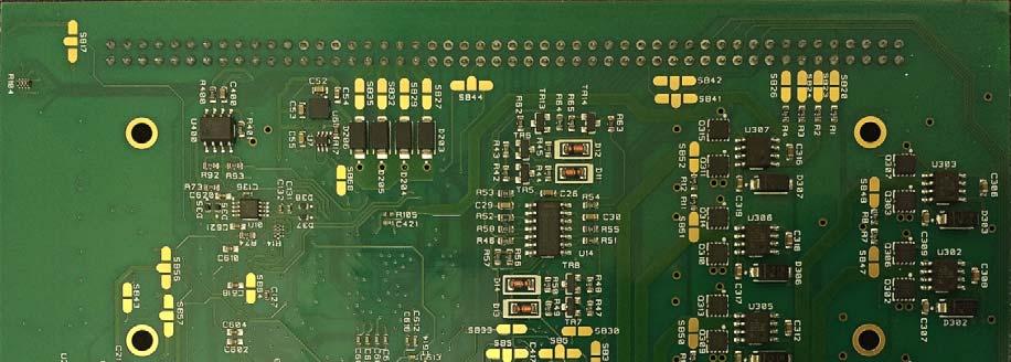
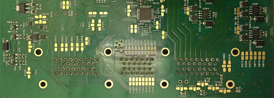
21 21 S6 I Solder Bridge settings The Syvecs S6 I is built to cater for many applications, with this in mind some of the advanced hardware can only be activated via Solder Joins/Solder Blobs. The use of conventional Jumpers inside an ecu designed to cater with the harshest environments is not wise where vibrations can cause loose connections. We use a Solder Bridges which is designed to take that out of the question. The Solder Bridges on the S6 I are either on a 2 position pad or 3 position, and easily found on the bottom board of the Ecu. They are easy to access by removing the front panel of the Ecu followed by the bottom panel shown below. By taking a small soldering iron and placing a small amount of solder on each pad and swiping the solder iron over the pads you can easily join pads to gain a connection. The Default Setting which a Generic Board comes with are shown Below Designed for use with Single NTK IMPORTANT!! Some of the Default Solder Bridge Settings are done via a PCB Track in between, Check carefully if adjusting Default settings that a track is not still in place, if so it needs cutting with a small blade to remove. An Example of this is on SB41 and SB42 that are set with a Track as Default to 1 2 so will need the track cutting to set on 2 3
22 22
Syvecs Limited. Syvecs S6Plus. Syvecs
 Syvecs Limited Syvecs S6Plus Pinouts and Wiring Info Support Team 03 02 2014 This document intended for use by a technical audience and describes a number of procedures that are potentially hazardous.
Syvecs Limited. Syvecs
 Syvecs Limited Syvecs S8 Pinouts and Wiring Info Support Team 03 02 2014 This document intended for use by a technical audience and describes a number of procedures that are potentially hazardous. Installations
Bmw E46 M3 Plug in Kit
 Bmw E46 M3 Plug in Kit Installation 1.) Remove the Negative Terminal from the battery on the Vehicle 2.) Remove the DME/Fuse Box cover found in the engine bay as shown below in red 3.) You will then find
Powerful RISC CPU for advanced strategy execution Custom synchronous FPGA processor for engine position tracking up to 25,000 rpm
 F90F ECU The F90F ECU caters for advanced and challenging applications. The twin processor unit uses a high speed RISC processor for code execution and an additional large FPGA for high speed engine position
Powerful RISC CPU for advanced strategy execution Custom synchronous FPGA processor for engine position tracking up to 25,000 rpm
 F90A ECU The F90A ECU caters for advanced and challenging applications. The twin processor unit uses a high speed RISC processor for code execution and an additional large FPGA for high speed engine position
Mini-Expansion Unit (MEU) User Guide V1.2
 User Guide V1.2") Mini-Expansion Unit (MEU) User Guide V1.2 Disclaimer Although every care is taken with the design of this product, JT Innovations Ltd. can in no way be held responsible for any consequential damage resulting
Mini-Expansion Unit (MEU) User Guide V1.2 Disclaimer Although every care is taken with the design of this product, JT Innovations Ltd. can in no way be held responsible for any consequential damage resulting
6 Repton Close Basildon Essex SS13 1LE United Kingdom +44 (0)
") 6 Repton Close Basildon Essex SS13 1LE United Kingdom +44 (0) 1268 904124 info@liferacing.com www.liferacing.com The F88GDi4 ECU sets the benchmark for integrated direct injection engine management. Based
6 Repton Close Basildon Essex SS13 1LE United Kingdom +44 (0) 1268 904124 info@liferacing.com www.liferacing.com The F88GDi4 ECU sets the benchmark for integrated direct injection engine management. Based
EM80. Advanced engine management system with 8 coil drivers, gearshift control and high speed logging. Specifications.
 EM80 Advanced engine management system with 8 coil drivers, gearshift control and high speed logging Specifications Parameter Operating Voltage Power Consumption Value 4V - 35 Volts 250mA Outputs 8 Ignition
Pectel SQ6M ECU. Introduction
 Pectel SQ6M ECU Introduction The Pectel SQ6M sets the benchmark for high-performance engine management systems. Its Motorola MPC565 microprocessor and dedicated timer co-processor bring class leading performance
Document No. 29E P Rev: 1aE
 The MQ12Di is a high-performance engine management system. Its two microprocessors, one dedicated to engine control and the other to data collection, and three Field Programmable Gate Arrays (FPGAs) provide
The SQ7Di is an integrated ECU and direct injection driver box for use with up to 6 cylinder Gasoline Direct Injection (GDI) Engines.
 Engines.") The SQ7Di is an integrated ECU and direct injection driver box for use with up to 6 cylinder Gasoline Direct Injection (GDI) Engines. The SQ7Di has been designed to run the Bosch HDEV5 direct injectors
The SQ7Di is an integrated ECU and direct injection driver box for use with up to 6 cylinder Gasoline Direct Injection (GDI) Engines. The SQ7Di has been designed to run the Bosch HDEV5 direct injectors
PLEASE READ FIRST (NEW 2011 VERSION) Main features:
 Main features:") PLEASE READ FIRST (NEW 2011 VERSION) Main features: engine control system, the user can set different types of crankshaft independent Signal output (for all models of the computer-driven) automatic transmission
PLEASE READ FIRST (NEW 2011 VERSION) Main features: engine control system, the user can set different types of crankshaft independent Signal output (for all models of the computer-driven) automatic transmission
kdfi V1.4 R03 (As from: 24 July. 2013)
") kdfi V1.4 R03 (As from: 24 July. 2013) User Manual (English) You will find the latest information, documentation and CD images on www.k-data.org 1 of 12 Index 1. INTRODUCTION 2. INCLUDED IN DELIVERY 3.
kdfi V1.4 R03 (As from: 24 July. 2013) User Manual (English) You will find the latest information, documentation and CD images on www.k-data.org 1 of 12 Index 1. INTRODUCTION 2. INCLUDED IN DELIVERY 3.
PRELIMINARY. Preliminary TECHNICAL DATASHEET #TDAX DC MOTOR CONTROLLER P/N: AX100650
 Preliminary TECHNICAL DATASHEET #TDAX100650 DC MOTOR CONTROLLER P/N: AX100650 Variable Speed Control, Onboard Inputs 6A DC Motor Output, 2.5A Proportional Output, 2 Signal Outputs CAN SAE J1939, Rugged
Vehicle Data Display and Logger Installation and Operation Manual Rev Focus Applied Technologies
 Vehicle Data Display and Logger Installation and Operation Manual Rev 1. 1-215 Focus Applied Technologies INTRODUCTION This Vehicle Data Display and Logger is designed as a robust display and logger for
Quick start / system check to ensure the DL1CLUBGTCUP is operating correctly
 Data Logger Quick start / system check to ensure the DL1CLUBGTCUP is operating correctly This test MUST be performed with the supplied SD-card inserted, power ON and in open air conditions (outside and
Bill of Materials: PWM Stepper Motor Driver PART NO
 PWM Stepper Motor Driver PART NO. 2183816 Control a stepper motor using this circuit and a servo PWM signal from an R/C controller, arduino, or microcontroller. Onboard circuitry limits winding current,
DMC-8 (SKU#ROB )
") DMC-8 (SKU#ROB-01-007) Selectable serial or parallel interface Use with Microcontroller or PC Controls 2 DC motors For 5 24 Volt Motors 8 Amps per channel Windows software included Fuse protection Dual
DMC-8 (SKU#ROB-01-007) Selectable serial or parallel interface Use with Microcontroller or PC Controls 2 DC motors For 5 24 Volt Motors 8 Amps per channel Windows software included Fuse protection Dual
TECHNICAL DATASHEET #TDAX INPUTS, 5 OUTPUTS VALVE CONTROLLER
 TECHNICAL DATASHEET #TDAX020510 6 INPUTS, 5 OUTPUTS VALVE CONTROLLER Up to 6 Digital, Analog or PWM Command Inputs 5 Independent Proportional or On/Off Outputs 1 +5V, 100 ma Reference Voltage CAN (SAE
Test Bench Timing V3.1
 Test Bench Timing V3.1 Purpose:...1 Suggested Test Procedure:...1 Pre Run Setup:...1 Input Control:...1 Left Panel:...1 Setup and Outputs:...1 Channel Parameters:...1 Sensor:...1 Digital Graph:...1 Signal
AiM Infotech. MoTec M4 and M48 ECUs. Release 1.02
 AiM Infotech MoTec M4 and M48 ECUs Release 1.02 This tutorial explains how to connect MoTec ECUs to AiM devices. 1 Supported models MoTec supported models are: M4 M48 2 Software check (M48 only) and configuration
The Development and Application of High Compression Ratio Methanol Engine ECU
 National Conference on Information Technology and Computer Science (CITCS 2012) The Development and Application of High Compression Ratio Methanol Engine ECU Hong Bin, 15922184696 hongbinlqyun@163.com
WIRING DIAGRAMS. particular system is designed to work. To get the most out of wiring diagrams,
 Mastering Complex WIRING DIAGRAMS Complicated wiring schematics offer a wealth of information but can be awfully difficult to decipher. Dividing them into smaller, more manageable bits can make your job
FrankenCIS Microsquirt Manual supplement Reanimotion International Pty Ltd
 FrankenCIS Microsquirt Manual supplement FrankenCIS All rights reserved. No parts of this work may be reproduced in any form or by any means graphic, electronic, or mechanical, including photocopying,
MRS ELECTRONIC DATASHEET CAN I/O AND PLC DESCRIPTION TECHNICAL DATA REGULATORY APPROVALS AND TESTING SOFTWARE/PROGRAMMING
 DESCRIPTION The versatile CAN I/O PLC with 14 inputs and outputs impresses with its compact design and its operating voltage range of 9 to 30 volts. It provides 8 I/Os that can be configured as inputs
7I33 / 7I33TA MANUAL Quad analog servo amp interface
 7I33 / 7I33TA MANUAL Quad analog servo amp interface V1.9 This page intentionally almost blank Table of Contents GENERAL.......................................................... 1 DESCRIPTION.................................................
LCC-10 Product manual
 LCC-10 Product manual Rev 1.0 Jan 2011 LCC-10 Product manual Copyright and trademarks Copyright 2010 INGENIA-CAT, S.L. / SMAC Corporation Scope This document applies to i116 motion controller in its hardware
ALM-CAN. Accurate Lambda Meter With CAN bus V2.6 COPY RIGHTS ECOTRONS LLC ALL RIGHTS RESERVED.
 ALM-CAN Accurate Lambda Meter With CAN bus V2.6 COPY RIGHTS ECOTRONS LLC ALL RIGHTS RESERVED Http://www.ecotrons.com Note: If you are not sure about any specific details, please contact us at info@ecotrons.com.
Brushed DC Motor Control. Module with CAN (MDL-BDC24)
") Stellaris Brushed DC Motor Control Module with CAN (MDL-BDC24) Ordering Information Product No. MDL-BDC24 RDK-BDC24 Description Stellaris Brushed DC Motor Control Module with CAN (MDL-BDC24) for Single-Unit
Stellaris Brushed DC Motor Control Module with CAN (MDL-BDC24) Ordering Information Product No. MDL-BDC24 RDK-BDC24 Description Stellaris Brushed DC Motor Control Module with CAN (MDL-BDC24) for Single-Unit
Analog Servo Drive 25A20DD
 Description Power Range NOTE: This product has been replaced by the AxCent family of servo drives. Please visit our website at www.a-m-c.com or contact us for replacement model information and retrofit
with Electronic Assistant
 TECHNICAL DATASHEET #TDAX021300 Valve Controller 6 On/Off P/N: AX021300 2 Analog and 3 Frequency Command Inputs 6 On/Off Outputs (Option: PWM) CAN (SAE J1939) with Electronic Assistant Features: 2 user
Emtron CAN Predefined Dataset 1
 Emtron CAN Predefined Dataset 1 August 2014 Table of Contents 1.0 Parameter Scaling... 3 2.0 Predefined Dataset 1 Transmit Packets... 6 2.1. Predefined Packet 1... 6 2 1.0 Parameter Scaling ALL data/parameters
The I/O specification of NIRA i7 is subject to change as new hardware revisions are introduced. Contact Nira Control AB for updated versions.
 Issued by: Page: David Björklund 1(1) Date: 2012-12-07 NIRA i7 s NIRA i7 is an engine management system designed by Nira Control AB. This document describes the input, output and communication channels
User Manual CTP4/8/16
 KMT - Kraus Messtechnik GmbH Gewerbering 9, D-83624 Otterfing, Germany, 08024-48737, Fax. 08024-5532 Home Page http://www.kmt-telemetry.com, Email: info@kmt-telemetry.com User Manual CTP4/8/16 4/8/16-channel
7I54 MANUAL Six channel 40V 3A Servo motor drive
 7I54 MANUAL Six channel 40V 3A Servo motor drive V1.1 This page intentionally almost blank Table of Contents GENERAL.......................................................... 1 DESCRIPTION.................................................
EMS EM-Tech Race Dash Manual Version 3.1
 EMS EM-Tech Race Dash Manual Version 3.1 Thank you for purchasing an EMS Race Dash. EMS Computers Pty Ltd Unit 9 / 171 Power St Glendenning NSW 2761 Australia Ph: +612 9675 1414 Email: support@fuel-injection.com
MC-1010 Hardware Design Guide
 MC-1010 Hardware Design Guide Version 1.0 Date: 2013/12/31 1 General Rules for Design-in In order to obtain good GPS performances, there are some rules which require attentions for using MC-1010 GPS module.
P/N: AX Applications: Typical applications can include: test stands; and industrial automation.
 Description: The universal motor controller, 100W, drives a brushed DC Motor up to 6A or a 3- phase BLDC motor up to 6A. It features two SAE J1939 ports. Interfacing with 12V or 24Vdc power, the controller
High Current DC Motor Driver Manual
 High Current DC Motor Driver Manual 1.0 INTRODUCTION AND OVERVIEW This driver is one of the latest smart series motor drivers designed to drive medium to high power brushed DC motor with current capacity
MC-1612 Hardware Design Guide
 LOCOSYS Technology Inc. MC-1612 Hardware Design Guide Version 1.0 Date: 2013/09/17 LOCOSYS Technology Inc. 1 General Rules for Design-in In order to obtain good GPS performances, there are some rules which
SSI-4 PLUS User Manual
 SSI-4 PLUS User Manual 1 SSI-4 PLUS... 2 1.1 Getting to Know the SSI-4 PLUS... 2 1.2 Channel Functions... 3 2 Wiring and Setup... 3 2.1 Powering the SSI-4 PLUS... 3 2.2 5V for External Sensors... 4 2.3
MBE - Fault Codes for EPA98 engines (non-egr)
") MBE - Fault Codes for EPA98 engines (non-egr) Text SPN PID/ text Grid Heater 45 PID 45 3 Open 14 Special Instructions. What fault condition triggers this fault? 12 Grid Heater defect Vehicle Speed Sensor
MBE - Fault Codes for EPA98 engines (non-egr) Text SPN PID/ text Grid Heater 45 PID 45 3 Open 14 Special Instructions. What fault condition triggers this fault? 12 Grid Heater defect Vehicle Speed Sensor
P/N: AX Applications: Off-highway construction equipment Municipal vehicles. Ordering Part Numbers:
 Features: Command messages are received through the CAN network (no physical inputs) 10 universal outputs of up to 2.5A are user selectable from the following types (up to a maximum of 7A of controller
TECHNICAL PRODUCT DATASHEET
 FORM-ENG-0018 REV A 06-02-03 ISO 9001 CERTIFIED Phone: (352) 629-5020 or 800-533-3569 Fax: (352)-629-2902 SUITABLE FOR OEM DISTRIBUTION ONLY TECHNICAL PRODUCT DATASHEET High Density PDM 21 Output / 10
PM50. Technical Data TECHNOSOFT. DSP Motion Solutions. Power Module for DC, Brushless DC and AC Motors. Version 3.0. PM50 v3.0.
 Version 3.0 PM50 TECHNOSOFT DSP Motion Solutions Power Module for DC, Brushless DC and AC Motors Technical Data Technosoft 2001 Technosoft 2001 1-1 PM50 v3.0 Technical Data TECHNOSOFT DSP Motion Solutions
CONSTRUCTIVE DOCUMENTATION 09/06/2003 WIRING. Dash ST1. Logger s pinout. How to power the gauge
 AIM DashST1 CONSTRUCTIVE DOCUMENTATION 09/06/2003 WIRING Notes: general-purpose wiring for Dash ST1. Version 1.01 Dash ST1 167 [6.57] GEAR 87 [3.43] 27 [1.06] x1000 rpm mod.416tg Dimensions in millimetres
ISO 9001 CERTIFIED. 607 NW 27th Ave Ocala, FL Phone: (352) or Fax: (352) OPERATION MANUAL
 or Fax: (352) OPERATION MANUAL") ISO 9001 CERTIFIED Phone: (352) 629-5020 or 800-533-3569 Fax: (352)-629-2902 ES-Key 12 PDM module (4 selectable polarity outputs) with 4 Inputs (selectable polarity) and 4 MFI Inputs P/N 610-00035 PAGE
ISO 9001 CERTIFIED Phone: (352) 629-5020 or 800-533-3569 Fax: (352)-629-2902 ES-Key 12 PDM module (4 selectable polarity outputs) with 4 Inputs (selectable polarity) and 4 MFI Inputs P/N 610-00035 PAGE
TECHNICAL DATASHEET #TDAX A DC MOTOR CONTROLLER P/N: AX Variable Speed Control, Onboard I/O CAN SAE J1939, Rugged Packaging
 TECHNICAL DATASHEET #TDAX102000 35A DC MOTOR CONTROLLER P/N: AX102000 Variable Speed Control, Onboard I/O CAN SAE J1939, Rugged Packaging with Electronic Assistant Features: Unidirectional or bi-directional
Jaguar Motor Controller (Stellaris Brushed DC Motor Control Module with CAN)
") Jaguar Motor Controller (Stellaris Brushed DC Motor Control Module with CAN) 217-3367 Ordering Information Product Number Description 217-3367 Stellaris Brushed DC Motor Control Module with CAN (217-3367)
Jaguar Motor Controller (Stellaris Brushed DC Motor Control Module with CAN) 217-3367 Ordering Information Product Number Description 217-3367 Stellaris Brushed DC Motor Control Module with CAN (217-3367)
WIRING SCHEMATICS FOR SOFTWARE VERSIONS 5.13 AND HIGHER
 55 S. Vineyard Avenue Ontario, CA 976 (909) 93-973 WIRING SCHEMATICS FOR SOFTWARE VERSIONS 5.3 AND HIGHER FOR CURTIS 39 CONTROLLER ON-ROAD VEHICLE CONVERSION FOR SINGLE AND WITH DUAL MOTOR APPLICATIONS
with Electronic Assistant
 Description: The quad valve controller provides precise, repeatable control of 4 proportional solenoids and 1 on/off solenoid over a SAE J1939 network. PWM signal inputs or analog voltage or current inputs
SilverMax Datasheet. QuickSilver Controls, Inc. NEMA 23 Servomotors.
 SilverMax Datasheet NEMA 23 Servomotors QuickSilver Controls, Inc. www.quicksilvercontrols.com SilverMax Datasheet - NEMA 23 Servomotors 23 Frame Sizes: 23-3, 23-5, 23H-1, 23H-3, 23H-5 / Series: E, E3,
ViM (Vehicle Interface Module) Setup
 Setup") ViM (Vehicle Interface Module) Setup The ViM ( Vehicle Interface Module ) is a CAN bus analog / digital input module designed to work with Aim products. 1.1 Import ViM CAN Protocol. Open Race studio 3
ViM (Vehicle Interface Module) Setup The ViM ( Vehicle Interface Module ) is a CAN bus analog / digital input module designed to work with Aim products. 1.1 Import ViM CAN Protocol. Open Race studio 3
National Instruments Direct Injector Driver System NI DIDS-2003 NI DIDS-2006 NI DIDS-2009 NI DIDS-2012
 National Instruments Direct Injector Driver System NI DIDS-2003 NI DIDS-2006 NI DIDS-2009 NI DIDS-2012 NI Direct Injector Driver System User Guide May 2014 Table of Contents National Instruments Direct
DigiFlex Servo Drive DPQNNIE-060A400
 Description The DigiFlex Performance (DP) Series digital servo drives are designed to drive brushed and brushless servomotors. These fully digital drives operate in torque, velocity, or position mode and
Using Motec Hundred Series ECU s with AEM CD-7 Displays. M400, M600, M800, M880 Transmitting Data Set #1
 Revision Date Initial Release Feb 10, 2017 Using Motec Hundred Series ECU s with AEM CD-7 Displays Supported Motec Hardware M400, M600, M800, M880 Transmitting Data Set #1 M84, M400, M600, M800, M880 Transmitting
KMPS-7 Owners Manual. What s in the box?
 Thank you for selecting the KEF KMPS-7 Power Supply. The KMPS-7 is designed for a plug and play installation when used with KEF motorized custom installation speaker model Ci200.3Qt (and Ci3-80Qt in the
DB Motorized Impeller
 DB928-2430 Motorized Impeller The air mover described in this specification is the DB928-4830. The unit is available a metal impeller blade. The following information includes performance characteristics,
DB Motorized Impeller
 DB824-4836 Motorized Impeller The air mover described in this specification is the DB824-4836. The unit is available a plastic impeller blade. The following information includes performance characteristics,
VFSC9 ELECTRONIC SPEED CONTROLLER. Mounting and operating instructions
 ELECTRONIC SPEED CONTROLLER Mounting and operating instructions Table of contents SAFETY AND PRECAUTIONS 3 PRODUCT DESCRIPTION 4 ARTICLE CODES 4 INTENDED AREA OF USE 4 TECHNICAL DATA 4 STANDARDS 5 WIRING
EVO4 Data Logger USER GUIDE
 EVO4 Data Logger USER GUIDE AiM Srl. Via Cavalcanti, 8 20063 Cernusco S/N (MI) Italia Tel. (+39) 02.9290571 Made in Italy www.aim-sportline.com EVO4 Data Logger 04 INTRODUCTION 08 GETTING STARTED 12 GENERAL
D200 UNIVERSAL HARNESS
 0 ir Old Park Ridge Rd. Suite Road www.ptcs.us (0) Phone: -0 (0) -0 shland, V 00 V 00 Fax: (0) Fax: -00 (0) - DRWN Y: DTE: //00 PGE: OF Splice : D00 UNIVERSL HRNESS Splice : PRT NUMER: UNIVERSL HRNESS
MGL Avionics Garrecht VT-0102 mode-s transponder Interface installation manual
 MGL Avionics Garrecht VT-0102 mode-s transponder Interface installation manual Document date: September 2012 This document should be read in conjunction with the Garrecht VT-0102 installation manual General
RP4-MZ11 Radio Replacement & Steering Wheel Control Interface for MazdaVehicles
 RP4-MZ11 for MazdaVehicles Introduction & Features The RP4-MZ11 interface allows the replacement of a factory radio in select Mazda vehicles with MS-CAN radios. Using this interface will retain factory
PRELIMINARY AVB250A060 PRELIMINARY. Servo Drive. Peak Current (10 seconds)
") Description Power Range The servo amplifiers are designed to drive brushless DC motors at a high switching frequency for vehicle applications. t is fully protected against over-voltage, over-current, over-heating,
Description Power Range The servo amplifiers are designed to drive brushless DC motors at a high switching frequency for vehicle applications. t is fully protected against over-voltage, over-current, over-heating,
7I33/7I33T MANUAL Quad analog servo amp interface
 7I33/7I33T MANUAL Quad analog servo amp interface V1.4 This page intentionally almost blank Table of Contents GENERAL.......................................................... 1 DESCRIPTION.................................................
7I30 MANUAL Quad 100W HBridge
 7I30 MANUAL Quad 100W HBridge V1.3 This page intentionally almost blank Table of Contents GENERAL.......................................................... 1 DESCRIPTION.................................................
P/N: AX TECHNICAL DATASHEET #TDAX Single Input, Dual Output Valve Controller 1 Universal Input, +5V reference CAN (SAE J1939)
") TECHNICAL DATASHEET #TDAX022000 Single Input, Dual Output Valve Controller 1 Universal Input, +5V reference (SAE J1939) Features: 1 universal signal input 2 proportional or on/off outputs up to 3 A User
TECHNICAL DATASHEET #TDAX022000 Single Input, Dual Output Valve Controller 1 Universal Input, +5V reference (SAE J1939) Features: 1 universal signal input 2 proportional or on/off outputs up to 3 A User
DM8010 tm. Hardware Reference Manual. Document Revision B3 May 16, 2018
 tm Hardware Reference Manual Document Revision B3 May 16, 2018 MICROKINETICS CORPORATION 3380 Town Point Drive Suite 330 Kennesaw, Georgia 30144 Tel: (770) 422-7845 Fax: (770) 422-7854 Table Of Contents
Applications: oil and gas equipment automation; off-highway machine automation; agricultural equipment
 Features: 6 Universal Signal Inputs are user configurable as: o 0-5V, 0-10V, 4-20mA or 0-20mA o 20Ω to 250 kω Resistive o 1 Hz to 10 khz PWM o Digital o Three of the inputs can be configured as a pulse
maxon document number:
 maxon document number: 791272-04 1 Table of contents... 2 2 Table of figures... 3 3 Introduction... 4 4 How to use this guide... 4 5 Safety Instructions... 5 6 Performance Data... 6 6.1 Motor data... 6
Hardware Guide. Control Made Simple. Model 401A Signal Generator
 Control Made Simple Model 401A Signal Generator Hardware Guide ON OFF LIMIT 1 2 3 4 RXD TXD POWER West Coast Office 1263 El Camino Real Menlo Park, CA 94025 Phone (650) 853-1444 Fax (650) 853-1405 www.flashcutcnc.com
EVDP610 IXDP610 Digital PWM Controller IC Evaluation Board
 IXDP610 Digital PWM Controller IC Evaluation Board General Description The IXDP610 Digital Pulse Width Modulator (DPWM) is a programmable CMOS LSI device, which accepts digital pulse width data from a
Blue Point Engineering
 Blue Point Engineering Instruction I www.bpesolutions.com Pointing the Way to Solutions! Animatronic Wizard - 3 Board (BPE No. WAC-0030) Version 3.0 2009 Controller Page 1 The Wizard 3 Board will record
RC Camera Control. User Guide v1.3 (RCCC v1.1) 11/7/2012
 11/7/2012") RC Camera Control User Guide v1.3 (RCCC v1.1) 11/7/2012 kristaps_r@rcgroups INTRODUCTION RC Camera Control board (RCCC) is multifunctional control board designed to for aerial photography or First Person
RC Camera Control User Guide v1.3 (RCCC v1.1) 11/7/2012 kristaps_r@rcgroups INTRODUCTION RC Camera Control board (RCCC) is multifunctional control board designed to for aerial photography or First Person
Peak Current. Continuous Current. See Part Numbering Information on last page of datasheet for additional ordering options.
 Description Power Range The PWM servo drive is designed to drive brushless DC motors at a high switching frequency. A single red/green LED indicates operating status. The drive is fully protected against
DB Motorized Impeller
 DB628-4818 Motorized Impeller The air mover described in this specification is the DB628-4818. The unit is available with either a metal or plastic impeller blade. In either case the wheel backplate is
HAW-Arduino. Sensors and Arduino F. Schubert HAW - Arduino 1
 HAW-Arduino Sensors and Arduino 14.10.2010 F. Schubert HAW - Arduino 1 Content of the USB-Stick PDF-File of this script Arduino-software Source-codes Helpful links 14.10.2010 HAW - Arduino 2 Report for
TECHNICAL REPORT NO The Sutherland Temperature Controllers. Ian Barnes. The University of Birmingham, Edgbaston, Birmingham B15 2TT
 ËÇÆ Birmingham Solar-Oscillations Network TECHNICAL REPORT NO. The Sutherland Temperature Controllers Ian Barnes The University of Birmingham, Edgbaston, Birmingham B TT 00 January This technical report
New Eagle PWM to Analog Converter
 New Eagle P.O. Box #272 Ann Arbor, MI 48105-2603 Phone 734.395.2112 Fax 928.395.2114 M E C H A T R O N I C C O N T R O L S O L U T I O N S New Eagle PWM to Analog Converter Revision 0.2 PWM-AN-024-1403
ADI-Spectra MX800 Series Base Connection to A800-SIM
 ADI-Spectra MX800 Series Base Connection to A800-SIM Issue No.: AN011-02 Author: TEA Engineering Updates - Note that any amendments/updates that are new to this document are indicated with a red line symbol
LABsat Manual Fall 2005
 LABsat Manual Fall 2005 This manual describes the USNA Laboratory Satellite System which has been designed to provide a realistic combination of all the aspects of satellite design including the Electrical
Analog Servo Drive. Peak Current 16 A (11.3 A RMS )
") Description The PWM servo drive is designed to drive three phase brushless motors with sine wave current at a high switching frequency. The drive requires two sinusoidal command signals with a 120-degree
Description The PWM servo drive is designed to drive three phase brushless motors with sine wave current at a high switching frequency. The drive requires two sinusoidal command signals with a 120-degree
BV4112. Serial Micro stepping Motor Controller. Product specification. Dec V0.a. ByVac Page 1 of 18
 Product specification Dec. 2012 V0.a ByVac Page 1 of 18 SV3 Relay Controller BV4111 Contents 1. Introduction...4 2. Features...4 3. Electrical interface...4 3.1. Serial interface...4 3.2. Motor Connector...4
DigiFlex Performance Servo Drive DPCANIA-060A400
 DigiFlex Performance Servo Drive DPCANA-060A400 Description Power Range The DigiFlex Performance (DP) Series digital servo drives are designed to drive brushed and brushless servomotors. These fully digital
Data Sheet. Stepper Motor Drive Boards. Features
 Data Pack B Issued March 0-6 Data Sheet Stepper Motor Drive Boards Unipolar stepper motor drive board (RS stock no. 7-6) and bipolar stepper motor drive board (RS stock no. -906) The unipolar drive board
SR3400 Base Station Module Configuration and Use Series-2 Cards Only
 SR3400 Base Station Module Configuration and Use Series-2 Cards Only A.W. Communication Systems Ltd Crook Barn, The Crook Rowel Town, Carlisle Cumbria Telephone (44) 1697-748777 Fax (44) 1697-748778 www.toneremote.com
Analog Servo Drive. Continuous Current. Features
 Description Power Range The PWM servo drive is designed to drive three phase brushless motors with sine wave current at a high switching frequency. The drive requires two sinusoidal command signals with
TECHNICAL DATASHEET #TDAX021901
 TECHNICAL DATASHEET #TDAX021901 8 In, 5 Output Valve Controller 6 Universal Analog Inputs, 1 Digital Input 1 Magnetic Pickup Sensor Input 4-2.5A Proportional or On/Off Outputs 1-2.5A Digital Output CANopen
Analog amplifier RA. RE Edition: Replaces:
 Analog amplifier RA RE 950 Edition: 08.05 Replaces: 0.006 For control of simple functions of electrohydraulic components Two power outputs (PWM) and one switching output Each output has a separately adjustable
RP4-MZ11 Radio Replacement & Steering Wheel Control Interface for MazdaVehicles
 Radio Replacement & Steering Wheel Control Interface for MazdaVehicles Introduction & Features The interface allows the replacement of a factory radio in select Mazda vehicles with MS-CAN radios. Using
The universal fluid flow monitoring system. User manual DDS3v10
 The universal fluid flow monitoring system User manual DDS3v10 WHAT DDS3v10 will do for you The DDS3 turbine based flow monitoring system has been serving the water/alcohol injection market for many years.
ME 461 Laboratory #5 Characterization and Control of PMDC Motors
 ME 461 Laboratory #5 Characterization and Control of PMDC Motors Goals: 1. Build an op-amp circuit and use it to scale and shift an analog voltage. 2. Calibrate a tachometer and use it to determine motor
Programmable with Electronic Assistant Simulink
 TECHNICAL DATASHEET #TDAX022410 2 Universal Inputs, Dual Valve Controller 2 Universal Signal Inputs 2-3A Outputs Drive Hydraulic Valves CAN (SAE J1939) Programmable with Electronic Assistant Simulink P/N:
All installation operations can only be carried out by qualified technicians who are suitably trained with respect to the relevant norms and laws.
 General instructions. General instructions This manual aims at providing information to install the ARM receiving unit of Autec Dynamic series radio remote controls. Information about transmitting unit's
ELEC3106 Electronics. Lab 3: PCB EMI measurements. Objective. Components. Set-up
 ELEC3106 Electronics Lab 3: PCB EMI measurements Objective The objective of this laboratory session is to give the students a good understanding of critical PCB level Electromagnetic Interference phenomena
CSG110 Strain Gauge Universal Amplifier
 Quick Start Guide CSG110 Strain Gauge Universal Amplifier Sensor Solutions Source Load Torque Pressure Multi-Axis Calibration Instruments Software www.futek.com Getting Help TECHNICAL SUPPORT For more
CNC4PC. C19 A/C FREQUENCY CONVERTER Rev. 4
 CNC4PC Manual C19 A/C FREQUENCY CONVERTER Rev. 4 Overview This unit is an easy to use speed controller for routers. It work by modifying the output frequency according to an external control signal. It
Installation Instructions for CMS Pro Meter (with Breakout Box Type-A) for Yamaha V-Max 1700
 for Yamaha V-Max 1700") Installation Instructions for CMS Pro Meter (with Breakout Box Type-A) for Yamaha V-Max 1700 Notes: (1) For the remainder of this document, Meter is referring to the Motoscope Pro Meter which comes with
Installation Instructions for CMS Pro Meter (with Breakout Box Type-A) for Yamaha V-Max 1700 Notes: (1) For the remainder of this document, Meter is referring to the Motoscope Pro Meter which comes with
GAUSS High Power UHF Radio
 [] Table of contents Table of contents... 1 1. Introduction... 3 Features... 4 Block Diagram... 6 2. Pinouts... 7 3. Absolute Maximum Ratings... 9 4. General Recommended Operating Conditions... 10 5. RF