National Instruments Direct Injector Driver System NI DIDS-2003 NI DIDS-2006 NI DIDS-2009 NI DIDS-2012
|
|
|
- Alexander Garrett
- 6 years ago
- Views:
Transcription
1 National Instruments Direct Injector Driver System NI DIDS-2003 NI DIDS-2006 NI DIDS-2009 NI DIDS-2012 NI Direct Injector Driver System User Guide May 2014
2 Table of Contents National Instruments Direct Injector Driver System About the NI Direct Injector Driver System Warnings REVERSE BATTERY POLARITY WARNING HIGH VOLTAGE WARNING Getting Started What Is Included Software SCM Software Installation Connecting To The DI Driver System Out Of The Box Connection Changing The Network Settings Of The DI Driver System Manually Resetting The Controller Network Interface To DHCP SCM and Windows Firewall Updating DI Driver System Controller Software Backing Up the DI Driver System Software Image Restoring A Backup Image To The DI Driver System Controller Hardware C-Series Module Slot Assignments Powering the System Connecting Injectors, Sensors and Actuators Direct Injectors to DI Driver Channels Port Fuel Injectors to PFI Channels Proportional Solenoid Valves to PFI Lowside Channels Digital Signals to NI 9411 Digital Input Module Analog Signals to NI 9215 Analog Input Module DI Driver System Component User Manual Reference Using DI Driver System to Control Fuel Pressure Optimizing The DI Driver System NI Direct Injector Driver System Interface DI Driver Setup Window DI Driver Scope Window PFI and LS Driver Setup Window PFI Module Control Tab PFI 1-4 Tab LS 1-4 Tab Digital Input Setup Window Analog Input Setup Window Pulse Generation Setup Window DI-TMP Tab DI-EPT Tab DI Advanced Settings Window PFI Tab Engine Position Tracking Setup Window EPT Tab TDC Channel Mapping Tab...130
3 Cam Phase Capture Tab EPT Diagnostics Tab Calibration Mode Setup Window Table Setup Window Table1D Table2D User Variables Auxiliary PID Controller Setup Window Rail Pressure Control Setup Window Auxiliary PWM Setup Window Operating Point Setup Window Active Flex Control Parameters Window CalScopes CalTrends Log Data Setup Window Faults Window Execution Information Window Static Info Network Run-Time Info Troubleshooting Diagrams Additional Support/Feedback Important Information Warranty Copyright Trademarks Patents Warning Regarding Use of NI Products Environmental Management...214
4 National Instruments Direct Injector Driver System NI DIDS-2003 NI DIDS-2006 NI DIDS-2009 NI DIDS-2012 NI Direct Injector Driver System User Guide May 2014
5 1. About the NI Direct Injector Driver System The NI Direct Injector Driver System features an NI CompactRIO controller, NI 9751 Direct Injector (DI) driver module(s), and NI 9411 digital input module(s). The system can synchronize injector channels with production crank/cam position sensors or research optical encoders. The system will also accept external digital fuel command signals from a production engine controller. The included DI driver module(s) provide the power electronics necessary to drive high-power solenoid or piezoelectric direct injectors. The NI Direct Injector Driver System comes in four different models corresponding to different direct injector channel configurations: the NI DIDS-2003 drives 3 solenoid injectors (or 2 piezoelectric injectors), the NI DIDS-2006 drives 6 solenoid injectors (or 4 piezoelectric injectors), the NI DIDS-2009 drives 9 solenoid injectors (or 6 piezoelectric injectors), and the NI DIDS-2012 drives 12 solenoid injectors (or 8 piezoelectric injectors). The systems provide a digital input per injector channel for directly commanding each injector. The system controller is delivered with a preinstalled feature-rich application. The deployment version of the NI Software Calibration Manager Toolkit (SCM) is included for interfacing with and calibrating the system. The NI Direct Injector Driver System supports optional C-series modules. The optional NI 9758 PFI driver module can be used to drive port fuel injectors, proportional solenoid valves and relays. The optional NI 9215 analog input module can be used for a variety of analog sensors. Common-rail fuel pressure control is an example feature of the NI Direct Injector Driver System that utilizes these modules. Throughout this manual, the model number NI 9751 and model name DI Driver module are used interchangeably. Similarly, the model number NI 9758 and model name PFI Driver are used interchangeably.
6 2. Warnings Please read the following warnings for your safety and that of the product.
7 2.1 REVERSE BATTERY POLARITY WARNING NI Powertrain Controls power modules are not internally protected against reverse battery polarity. Do not reverse the battery polarity or damage will occur. This event is not covered under warranty. All NI Powertrain Controls modules with a 10-pin screw terminal block have identical external power and ground connections. Please take necessary precautions to ensure that BATT (0) and GND (9) are not connected in reverse polarity. The BATT (0) terminal will accept positive 7-32VDC with respect to the GND (9) terminal. Please refer to the user manual for details. To provide system-level protection against reverse battery polarity, implement the following simple external main-power-relay circuit: Figure 2.1.a, Reverse Battery Protection Diagram Notes: 1.) The relay shown is a type of automotive relay which includes an internal series diode with terminal 85. This diode will prevent reverse battery from energizing the relay. 2.) Terminals 30 and 87 are screw terminals and should be connected with soldered ring terminals. 3.) Terminals 85 and 86 are X inch (6.3 X 0.8 mm) push-on terminals. 4.) A fuse is recommended between the battery and relay. 5.) An optional switch may be placed in series with relay terminal ) Simply placing a high-current-capacity diode in series with the system power is not an acceptable method of reverse battery protection because it will not allow the NI Powertrain Controls modules to perform current recirculation while switching inductive loads. 7.) The relay is currently available from


8 2.2 HIGH VOLTAGE WARNING HIGH VOLTAGE: This device is capable of operating at voltages up to 190V. Extreme care should be taken to protect against shock. Even when the device is completely powered down, allow approximately five minutes for the internal high voltage to dissipate. Do not touch any of the driver module screw terminals or injector terminals while the device is powered.
9 3. Getting Started This guide will provide instructions to set up the National Instruments Direct Injector Driver System hardware and software.


10 3.1 What Is Included Software DI Driver System software image preinstalled on the system controller NI Software Calibration Management Toolkit (SCM) for LabVIEW 2013, downloaded from Hardware 1. Direct Injector Driver System DI Driver System crio-9076 Integrated Controller and Chassis DIDS-2003 crio-9022 Controller crio-9114 Chassis NI 9411 Digital Input Module NI 9751 DI Driver Module DIDS DIDS DIDS Table 3.1.a, I/O Hardware Included In The DI Driver System Optional I/O modules supported by all DI Driver Systems NI Channel, 100 ks/s/ch, 16-bit, ±10 V Analog Input Module (P/N: ) NI 9758 PFI Driver Module (P/N: ) 2. Piezo Injector Inductors (P/N: ) Piezo Injector Inductor Packs Included In Each DI Driver System DI Driver System Number of Inductors DIDS (1 pack) DIDS (2 packs) DIDS (3 packs) DIDS (4 packs) Table 3.1.b, Number of Inductors Included With The DI Driver System
 4.")
 per NI 9411 Module")
11 3. Reverse Battery Protection Relay (P/N: ) 4. NI 9411 Module Breakout Harness(es) per NI 9411 Module (P/N: )
12 3.2 Software
 must be downloaded and installed to a PC with Windows 7 or newer. To download SCM follow the link below.")
13 Software Download SCM Software Installation At the time of shipping, the DI Driver System controller is pre-programmed with the latest version of software. However, in order to interact with the system, NI Software Calibration Management Toolkit (SCM) must be downloaded and installed to a PC with Windows 7 or newer. To download SCM follow the link below. Download SCM Software The link will take you to this webpage; click on download to begin the download process. Enter your NI User Account information as directed. If you do not have an NI User Account, create one for free and then proceed.

14 Download the LabVIEW 2013 version of the software. When prompted, choose the option to save the file NI_SCM_2013.zip.


15 Software Installation After the download is complete, browse to the location on disk where the file was saved. Extract the contents of the.zip file. After extracting the file, open the created directory and run the Setup.exe application. If prompted, install Microsoft.NET Framework 4.0. When prompted at the User Information screen, enter the relevant information and select the option to install the evaluation version of the license. The evaluation license is a free, perpetual license of SCM that allows users to interface to SCM-supported targets, but does not allow them to modify any code.

16 From there, follow the instructions and prompts to finish installing the software.
17 3.2.2 Connecting To The DI Driver System This section provides information about connecting to the DI Driver System user interface via SCM and how to change the network interface settings of the system controller.

18 Out Of The Box Connection This section describes how to establish a connection with the DI Driver System user interface via SCM. NI ships the DI Driver System with an IP address of and a Subnet mask of The Windows PC used to interface with the system must have a similar IP address and Subnet mask, but the IP address must be different in the last address number. The directions below illustrate how to make the initial network connection to the system and open the system user interface. 1. The customer must provide a Windows 7 (or later) PC with an Ethernet LAN port. 2. Install SCM for LabVIEW 2013 to the PC. 3. Check the Windows Firewall settings or 3rd party firewall settings to allow SCM to communicate with the external system. 4. Power up the DI Driver System controller. The DI Driver and PFI Driver modules do not need to be powered if simply attempting to establish a connection to the user interface. Wait about 1 minute for both the USER1 and USER FPGA LEDs to start blinking. 5. Using a CAT5E Ethernet cable, connect the Windows PC LAN port directly to the Ethernet port of the crio-9076 or Ethernet port 1 of the crio-9022 controller. If the green and amber LEDs directly under the controller Ethernet port are not active, then there is no physical Ethernet connection to the PC. Please diagnose the Ethernet cable connection problem. 6. Go to the Windows Control Panel and select Network and Sharing Center. From the Network and Sharing Center select Change adapter settings from the left menu. 7. A list of network connections available on the PC will open. Right click the Local Area Connection port to select Properties.
 Properties dialog, select the Use the following IP address radio button. Enter 192.168.1.101 for the IP address: field. Enter 255.")
19 8. From the Local Area Connection Properties dialog, scroll down to select Internet Protocol Version 4 (TCP/ IPv4) and select the Properties button below the scroll window. 9. From the Internet Protocol Version 4 (TCP/IPv4) Properties dialog, select the Use the following IP address radio button. Enter for the IP address: field. Enter for the Subnet mask: field. Select OK on the Internet Protocol Version 4 (TCP/IPv4) Properties dialog and the Local Area Connection Properties dialog to accept the IP address changes.


20 10. Open the NI SCM console from the Windows Start menu under National Instruments >> Software Calibration Management. 11. Within the SCM console, right-click inside the Target Items list pane and select Select Target.


21 12. A dialog will open titled Search for SCM Target If the Windows PC and the system controller have compatible network settings, then SCM will locate the DI Driver System on the network automatically. A Download Files checkbox will be presented within the dialog box and should be checked before pressing the OK button. After pressing OK, SCM will take about 30 seconds to download several files from the DI Driver System, including the user interface windows. SCM will store these files in the Windows user "Documents\LabVIEW Data\SCM Data" directory. The location of these files, and the IP address of the system controller, will be remembered on each successive opening of the SCM console, and are used to establish a connection with the system. Therefore this Search for SCM Target... step only needs to be done once or each time the IP address of the system controller is changed. 13. After the FTP Download process is complete, the SCM console will be populated with information as shown below. If the Host VI list (lower center) is not populated as shown below, it may be that the FTP download process
 to start the DI Driver System main user interface.")
22 did not fully complete. If this is the case, please attempt the Search for SCM Target... step again. If the FTP download process fully completes, the green run button (2nd from left) will be enabled. 14. Press the green run button (2nd from left) to start the DI Driver System main user interface. The main user interface window contains a list of all setup windows used to configure the various DI Driver System functions. Double-clicking on a setup window name will open the window and make the listed name bold. Multiple setup windows may be open simultaneously. Pressing the X in the upper right corner of each window will close the window. Also, double clicking the bolded window name within the main window list will close the window. A single click of a bolded window name will bring the selected window to the top with focus. Pressing the X in the upper right corner of rd the main user interface window, or pressing the red square button in the SCM console (3 from left) will close all open setup windows and stop user interface communications with the DI Driver System. However, the system will still continue to operate according to the most recent user interface settings. The user interface can be started again by pressing the green run button within the SCM console. The DI Driver System can operate automatically, when powered up, according to settings saved to a system calibration file. The calibration file can be saved while the user interface is open by pressing the purple default th calibration save button from the SCM console (4 from left). The default save function will save all current settings within the setup windows to the default calibration file. The default calibration file is located on the DI Driver System controller at C:\system\ni-rt\LabVIEW Data\DefaultCal.cdl. The file system of the DI Driver System controller can be browsed using an FTP client. A recommended FTP client is FileZilla. It is not recommended to use the FTP connection within the Windows file Explorer. Please refer to the NI Direct Injector Driver System Interface for documentation of the parameters in the setup windows.
23 15. If it is desired to change the network settings of the DI Driver System controller, refer to Changing The Network Settings Of The DI Driver System.
24 Changing The Network Settings Of The DI Driver System This section assumes that a connection with the DI Driver System user interface is already established, and it is desired to change the IP address. If a connection has never been established, please refer to Out Of The Box Connection. If the IP address of the DI Driver System is unknown and a connection with the user interface cannot be established, please refer to Setting the Controller Network Interface To DHCP. 1. After starting the system main user interface, double-click on the Execution Information window. 2.) After the Execution Information window opens, select the Network tab to make changes to the controller network settings. The settings shown on this tab are similar to the Windows PC LAN TCP/IPv4 Properties dialog. The image below shows an example of changing the controller IP address to The Default Gateway and DNS Server IP addresses may be important if the system is connected to a network router. A network administrator should be contacted for this information. If a direct, "point-to-point" network connection is made between the Windows PC and the system controller, both Default Gateway and DNS Server addresses may be set to The Windows PC used to interface with the system must have a similar IP address and Subnet mask as the system controller, but the IP address must be different in the last address number.
25 If the Windows PC and the system controller are placed in DHCP mode and connected to a network router acting as a DHCP server, then both devices will be served IP addresses on the same subnet automatically. If the system controller must be served an IP address from a router automatically, then select the Obtain an IP address automatically radio button. This will cause the other IP address settings to be disabled, and the controller's network interface will be placed in DHCP mode. NI does not recommend using DHCP mode for the DI Driver System controller because the IP address may change each time the system is powered. Each time the IP address changes, the Search for SCM Target... dialog must be opened within the SCM console to locate the system on the network. If the system controller network interface is in DHCP mode, and the controller is not connected to a DHCP router, the controller will default to a link-local IP address of X.X. If this happens, a connection with the system can still be established via direct, "point-to-point" if the Windows PC LAN IP address is configured to a similar IP address, but different in the last address number. After making changes to the network settings, select the Apply Change button associated with the changed settings. 3. Reset the controller, or cycle the controller power, to reboot the system. Wait for the USER1 and USER FPGA LEDs to start blinking before performing the Search for SCM Target... step.

26 Manually Resetting The Controller Network Interface To DHCP This section assumes that all attempts have failed to establish connection with the DI Driver System user interface, and the system controller IP address is unknown. Before resetting the controller network settings to DHCP mode, consider the following: 1. Reboot the System Controller Press and release the reset button on the front of the crio-9076 or crio-9022 controller. Wait about 1 minute for both the USER1 and USER FPGA LEDs to start blinking. The typical time to start blinking is about 25 seconds. A connection cannot be established with the user interface via SCM until both User LEDs are blinking. If both LEDs are not blinking, refer to the Troubleshooting section. 2. Use Search for SCM Target... to Discover the IP Address If the IP address of the controller is discovered via the Search for SCM Target... dialog, but the Download Files checkbox does not appear in the dialog, then take note of the discovered IP address. The Windows PC used to interface with the system must have a similar IP address and Subnet mask as the system controller, but the IP address must be different in the last address number. The Subnet mask should be Refer to the Out Of The Box Connection section to see how to change the IP address of the Windows PC. 3. Use SCM Real-Time Target Backup Feature to Discover the IP Address From the SCM console, select File, then Real-Time Backup and Restore to open the Real-Time System Backup dialog. Select the Backup Real-Time System button to open the Backup Target dialog. Select the Browse button to open the Select RT System dialog.

27 This will cause SCM to search the network for a National Instruments RT controller, such as the crio-9076 or crio If the DI Driver System controller is discovered, take note of the discovered IP address. The Windows PC used to interface with the system must have a similar IP address and Subnet mask as the system controller, but the IP address must be different in the last address number. The Subnet mask should be Refer to the Out Of The Box Connection section to see how to change the IP address of the Windows PC. The Select RT System dialog may be exited by selecting the Cancel button. The Backup Target dialog may be exited by selecting the Back button. The Real-Time System Backup dialog may be exited by selecting the Exit button. 4. Check the System Controller Ethernet Cable Connection


28 If the green and amber LEDs directly under the controller Ethernet port are not active or blinking, then there is no physical connection to a network router or PC, or there is no power to the controller. Please diagnose the Ethernet cable connection or controller power problem. If none of the above suggestions resolve the system connection problem, follow the instructions below to reset the system controller network interface settings to DHCP. crio-9076 Controller To manually reset the network settings of the crio-9076 controller included with 3-channel DI Driver Systems, follow the steps below: 1. Power up the crio-9076 controller. 2. Press and hold the reset button for greater than 5 seconds. Release the reset button. This will cause the controller to reboot into safe mode and the DI Driver System software will not load. This is indicated by the amber Status LED blinking 3 times. 3. Again, press and hold the reset button for greater than 5 seconds (while booted into safe mode). Release the reset button. This will cause the controller to reboot into safe mode AND reset the network interface settings to DHCP mode. 4. Press and immediately release the reset button. This will cause the controller to reboot normally and start the DI Driver System software. Wait about 1 minute for both the USER1 and USER FPGA LEDs to start blinking. crio-9022 Controller To manually reset the network settings of the crio-9022 controller included with 6-, 9-, and 12-channel DI Driver Systems, follow the steps below: 1. Power up the crio-9022 controller. 2. Switch the IP RESET switch to ON. 3. Press and immediately release the reset button. This will cause the controller to reboot normally and start the DI Driver System software. However, the network settings will be reset to DHCP mode. Wait about 1 minute for both the USER1 and USER FPGA LEDs to start blinking. 4. Switch the IP RESET switch to OFF.

29 Note: NI does not recommend leaving DHCP mode for the DI Driver System controller because the IP address may change each time the system is powered. Each time the IP address changes, the Search for CalVIEW Target... dialog must be opened within the CalVIEW console to locate the system on the network. If the system controller network interface is in DHCP mode, and the controller is not connected to a DHCP router, the controller will default to a link-local IP address of X.X. If this happens, a connection with the system can still be established via direct, "point-to-point" if the Windows PC LAN IP address is configured to a similar IP address, but different in the last address number. If the system controller is allowed to default to the link-local address, follow the instructions above for Use CalVIEW "Backup Target" Feature to Discover the IP Address to identify the exact link-local IP address.

30 SCM and Windows Firewall After installing SCM, if Windows Firewall is enabled, SCM should be added to the list of Allowed Programs to communicate through the Windows Firewall. Since SCM must communicate with the DI Driver System via a Ethernet LAN port, it is important that Windows Firewall be configured to allow SCM, and its associated programs, access to the network. SCM and its associated programs use UDP, TCP/IP, and FTP protocols. Sometimes, certain Windows settings prevent SCM from being added to the Allowed Programs list. The Allowed Programs list can be checked by following the instructions below. The PC used for interfacing with the DI Driver System may have the Windows Firewall turned off. In this case, the Allowed Programs list is not applicable and does not need to be checked. If the Windows Firewall is turned on, it may be possible to turn it off, if allowed by the network administrator. Some PCs may use a different software firewall other than Windows Firewall and will need to be configured properly to allow SCM to communicate with the DI Driver System IP address via UDP, TCP/IP, and FTP protocols. Checking the Windows Firewall Allowed Programs List The Windows Firewall configuration can be opened by going to the Windows Start menu and entering "Windows Firewall" in the search field. Select Windows Firewall from the Start Menu search results to open the configuration window. The screen shot below is a general representation of what may be seen if the Windows Firewall is on.

31 If Windows Firewall is on, and it is desired to turn it off, select Turn Windows Firewall on or off from the left menu and select the radio buttons as shown below.

32 To check the list of Allowed Programs, return to the main Windows Firewall window and select Allow a program or feature through Windows Firewall from the left menu.
 and Public check boxes are checked. Select OK and close the Windows Firewall window. If the above programs are not in the list, select Allow another program.")
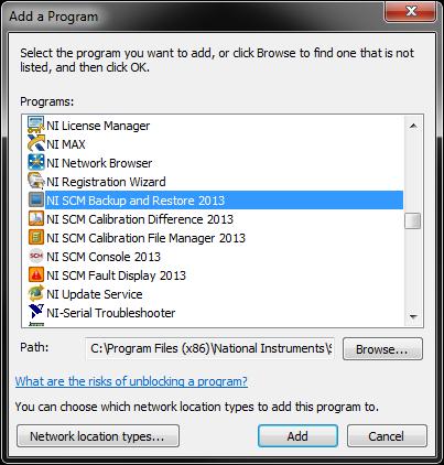
33 Scroll through the list of programs and look for the following programs: SCM Console NI Backup and Restore NI SCM Calibration Difference NI SCM Calibration File Manager NI SCM Fault Display Confirm that both Home/Work (Private) and Public check boxes are checked. Select OK and close the Windows Firewall window. If the above programs are not in the list, select Allow another program... to open the Add a Program dialog to add each of the programs. After adding the programs, confirm that both Home/Work (Private) and Public check boxes are checked.
34

35 3.2.3 Updating DI Driver System Controller Software Occasionally NI will generate updates to the DI Driver System controller software and provide a link to the latest update software on the DI Driver System product page. The software update is provided in the form of a.upd file downloaded in a.zip file and is a complete hard drive image replacement for the crio controller. NI provides an updater utility for download from the DI Driver System product page. The utility is called the DI Driver System Updater and is provided in the form of a.zip file, along with the.upd file. The zip file contains a.exe file which must be executed on the same Windows PC where SCM is installed. *Note: The.zip file downloaded contains both the.exe and.upd files. The software update utility and associated.upd files are only compatible with existing DI Driver Systems using crio-9076 and crio-9022 controllers. A software update cannot be performed on new crio controllers without a working copy of the DI Driver System software. NOTE: The system controller network interface settings are not changed by updating the software image. The DI Driver System must be in static IP address mode for the update to restore correctly. For more information on changing your system to static IP mode see Changing The Network Settings Of The DI Driver System. To update the DI Driver System controller software, following the instructions below: 1. Take note of the DI Driver System software version on the Static Info tab of the Execution Information window of the user interface. 2. Using a web browser, navigate to the DI Driver System product page and check the version of the software update. If the software update is a later version than the currently running software, download it to the PC. 3. Download the updater utility zip file to the PC and unzip it to produce the executable. 4. Run the DI Driver System Updater utility to see the dialog shown below. 5. Enter the IP address of the DI Driver System in the Target IP Address field. Press the refresh button to the right. The information window in the middle of the dialog will provide information about the controller discovered at the


36 specified IP address. If the controller at the specified IP address is valid, then the Begin Update button at the bottom will be enabled. 6. Two options are available for selection before beginning the update process. a. Backup target before update: This option may be selected if it is desired to create a backup image of the system controller before updating the software to the latest version. If selected, a Zip file save dialog will open to select the path and name of the backup zip file to be saved. b. Preserve calibration files: This option may be selected if it is desired to preserve the current calibration files on the system controller. Otherwise the current calibration files on the system controller will be overwritten during the software update process. 7. Press the "Begin Update" button at the bottom to start the software update process. The process will take about 5 to 10 minutes. During the update process, the cursor will show as busy while hovered over the dialog. When the process completes, a beep sound will be generated and the controller will be rebooted. Wait for the USER1 and USER FPGA LEDs to start blinking and then use the Search for CalVIEW Target... feature of CalVIEW to reconnect to the controller and download the new user interface files from the controller. It is important to check the Download Files check box within the Search for CalVIEW Target... dialog in order to have the user interface files compatible with the updated system software.
37 3.2.4 Backing Up the DI Driver System Software Image A DI Driver System software backup image can be created by following the instructions below. It is recommended this procedure be performed after the system has been calibrated and ready for deployment. *Note: The DI Driver System must be in static IP address mode for the backup to restore correctly. For more information on changing your system to static IP mode see Changing The Network Settings Of The DI Driver System. 1. Open the SCM console and select Backup Target from the File menu to open the Real-Time System Backup dialog. 2. Select the Backup Real-Time System button to open the Backup Target dialog. Select the Browse button to open the Select RT System dialog. 3. This will cause SCM to search the network for a National Instruments RT controller, such as the crio-9076 or crio Select the line associated with the system. Press OK to close the dialog and return to the Backup Target dialog.
38 4. The selected target IP Address should be listed in the IP Address field and additional target information will be shown in the Target Description field. 5. In the lower half of the Backup Target dialog, press the Backup Target button to browse the PC to specify the location to save the DI Driver System software image zip file. Select OK to close the location selection dialog. 7. During the image backup process, the PC cursor will indicate busy while hovering over the Backup Target dialog. The process will take about 3 minutes. 8. When the backup process is completed, press the Back button to close the Backup Target dialog to return to the Real-Time System Backup dialog. 9. Press the Exit button to close the Real-Time System Backup dialog.
39 3.2.5 Restoring A Backup Image To The DI Driver System Controller If the USER1 and USER FPGA LEDs are not blinking at all, please try pressing and immediately releasing the controller reset button. Wait 1 minute for the LEDs to start blinking. If they do not start blinking, follow the instructions below for restoring a backup image zip file to the system controller. If a system backup image is not available, please contact the National Instruments support team. A DI Driver System software backup image can be created by following the instructions in Backing Up the DI Driver System Software Image section. It is recommended this procedure be performed after the system has been calibrated and ready for deployment. WARNING: Restoring a software image to the system controller will overwrite the entire system hard drive. If a critical calibration file is stored on the controller, it should be retrieved before restoring the backup image. Step 1 below provides the optional instructions for retrieving the calibration file. NOTE: The system controller network interface settings are not changed by restoring the software image. The DI Driver System must be in static IP address mode for the backup to restore correctly. For more information on changing your system to static IP mode see Changing The Network Settings Of The DI Driver System. 1. Using an FTP client, connect to the DI Driver System controller and browse to C:\ni-rt\LabVIEW Data\. Copy any.cdl calibration files from the crio controller to the PC for backup. The default calibration file is named DefaultCal.cdl. This is important because the image restoration process will overwrite all files on the controller. This step is only necessary if calibration files have previously been saved and contain important system settings. 2. Open the SCM console and select Backup Target from the File menu to open the Real-Time System Backup dialog. Press the Restore Real-Time System button to open the Restore Target dialog. 3. Press the Browse button to open the Select RT System dialog to allow SCM to find the system on the network.

40 4. Select the line associated with the system. Press OK to close the dialog and return to the Restore Target dialog. 5. The selected target IP Address should be listed in the IP Address field and additional target information will be shown in the Target Description field. 6. In the lower half of the Restore Target dialog, press the Restore Target button to browse the PC for the DI Driver System software image zip file. Select the zip file and press OK.
41 8. During the image restoration process, the PC cursor will indicate busy while hovering over the Restore Target dialog. The process will take about 3 minutes. 9. When the restoration process is completed, press the Back button to close the Restore Target dialog to return to the Real-Time System Backup dialog. 10. Press the Exit button to close the Real-Time System Backup dialog. 11. After the image restoration process, the DI Driver System will be rebooted automatically. Wait for the USER1 and USER FPGA LEDs to start blinking, indicating the DI Driver System application is running. 12. If calibration files were backed up in step 1, use an FTP client to restore any.cdl calibration files. The.cdl calibration files on the system controller should be located at C:\ni-rt\LabVIEW Data\. After restoring the calibration file, reset the controller or cycle the power.
42 3.3 Hardware
43 3.3.1 C-Series Module Slot Assignments NI DIDS Channel Direct Injector Driver System The NI DIDS-2003 DI Driver System includes a crio-9076 integrated controller and chassis with four slots. The slot assignments for the NI DIDS-2003 system are shown in figure a, with the ability to add optional NI 9215 and NI 9758 (PFI Driver) modules (purchased separately). The DI Driver System software can only communicate with the modules when they are in their assigned slots shown in figure a. Figure a, 3-Ch DI Driver System Configuration With Optional NI 9215 and PFI Driver *The NI 9215 and NI 9758 (PFI Driver) modules are optional modules that may be purchased separately. For more information on the functionalities of these modules please see Using The DI Driver System to Control Fuel Pressure. NI DIDS-2006, NI DIDS-2009, and NI DIDS , 9- and 12-Channel Direct Injector Driver Systems The NI DIDS-2006, NI DIDS-2009, and NI DIDS-2012 DI Driver Systems include a crio-9022 controller and a crio slot chassis. The slot assignments for the NI DIDS-2006, NI DIDS-2009, and NI DIDS-2012 DI Driver Systems are shown in figure b. It is possible to upgrade an NI DIDS-2006 or NI DIDS-2009 DI Driver System to a NI DIDS DI Driver System by adding a NI 9411 and NI 9751 (DI Driver) modules. System I/O may be expanded with optional NI 9215 and NI 9758 (PFI Driver) modules (purchased separately). For more information on the hardware included see, What Is Included. The DI Driver System software can only communicate with the modules when they are in their assigned slots shown in figure b. The NI 9411 modules can communicate with the any of the DI Driver modules in their appropriate slots. For example, the NI 9411 module in Slot 1: NI 9411_1 has the ability to communicate digital input signals to any of the DI Drivers in Slots 2, 3, 5 or 6. Please note the nomenclature of the DI Drivers and their corresponding slots, as this the identification used in the application interface.
44 Figure a, 6-, 9-, and 12-Ch DI Driver System Configuration With Optional NI 9215 and PFI Driver *The NI 9215 and NI 9758 (PFI Driver) modules are optional modules that may be purchased separately. For more information on the functionalities of these modules please see Using The DI Driver System to Control Fuel Pressure.
45 3.3.2 Powering the System Warning: The external battery supply input terminals on the NI 9751 (DI Driver) and NI 9758 (PFI Driver) modules are not reverse-voltage polarity protected. Connecting power to the module in reverse polarity will damage the modules. This event is not covered by the warranty. Please refer to the Reverse Battery Polarity Notice for a recommended solution for protecting a system from reverse battery polarity. The DI Driver System requires external DC power to the following system components: Power Terminal Label Ground Terminal Label Voltage Range Maximum Required Power crio-9076 (3-Channel System) V C 9-30 V 15 W crio-9022 (6, 9, 12-Channel Systems) V1 C 9-35 V 35 W NI 9751 Modules 1-4 BATT (0) GND (9) 9-32 V 75 W Each NI 9758 Module BATT (0) GND (9) 9-32 V 75 W NI 9411 Modules* Vsup COM 5-30 V 1W Component a, Power Supply Specifications for I/O Hardware *The NI 9411 module only needs external power supplied to the screw-terminal block if 5V regulated output power is required from the 15-pin D-Sub connector to an optical encoder. Do not connect external power to the 15-pin D-Sub. NI recommends the following power supply options for powering the system components: NI Part Number Model Number Input Voltage Output Voltage Output Current QS VAC V 15A PS VAC V 20A b, Power Supply Recommendations for the DI Driver System The power supplies listed above are not included with the DI Driver System, but are available through National Instruments. There are a few considerations for selecting the proper power supply system specifically whether to use a 12V power supply (QS10.121) or a 24V power supply (PS-17). NI recommends using a 24V power supply in order to increase the efficiency of the DI Driver modules internal boost supply. However, if an optional PFI Driver module is used, and the associated actuators are not rated for 24V, then the lower 12V power supply should be used. DI Driver Systems with one or two DI Driver modules (DIDS-2003 and DIDS-2006) can typically be powered by a single recommended supply listed above. DI Driver Systems with three or four DI Driver modules (DIDS-2009 and DIDS-2012) should be powered by two identical supplies wired in parallel. Power supplies wired in parallel will create a supply having the same voltage as the individual supplies, but double the current capacity. Please refer to the power supply documentation for wiring instructions.
46 Power Wiring Guidelines NI recommends powering and grounding each component in the system in a star-wiring configuration, such that each component is wired individually from a single star-point for both positive and negative terminals of the power supply buses. In contrast, it is not recommended to power the components in a daisy-chain configuration because it will cause some modules to experience supply voltage fluctuations. NI recommends using crimped ferrules on all wires entering screw terminal connections. DI Driver System Component Diagrams and Connector Pinouts
47 3.3.3 Connecting Injectors, Sensors and Actuators
48 Direct Injectors to DI Driver Channels Connecting Direct Injectors to the Direct Injector (DI) Driver Module Direct injectors have two pins or wire leads. For solenoid injectors, the polarity of the injector leads typically does not matter. However, the polarity does matter for piezo injectors. Each DI Driver module has three channels and provides a positive and negative terminal for each channel labeled INJX+ and INJX-, where X represents the channel number. Solenoid and piezo injectors cannot be mixed within a DI Driver module. The DI Driver module supports three channels for solenoid injectors and two channels for piezo injectors. When the module is configured for piezo mode, channels 1 and 2 are available as driver channels, while channel 3 is unavailable and must be wired with a shorting jumper across the positive and negative terminals. Solenoid Injector Wiring Typical wiring for solenoid injectors to a DI Driver module is shown in figure a.
49 Figure a, Diagram of Typical Wiring of Solenoid Injectors to a DI Driver Module Piezo Injector Wiring Driving piezo injectors requires in-series inductance on the high side wire (INJX+ wire) and shorting of channel 3. Shorting channel 3 is required to discharge the piezo actuator of channel 1 and channel 2. This means that each DI Driver module can only operate two (2) channels of piezo injectors. NI provides two (2) piezo inductors per DI driver module in a DI Driver System order. Typical wiring for piezo injectors to a DI Driver module is shown in figure b. Figure b, Diagram of Typical Wiring of Piezo Injectors to a DI Driver Module
50 Port Fuel Injectors to PFI Channels The DI Driver System supports an optional PFI Driver module. The PFI Driver module has four channels, PFI1 PFI4, for driving port fuel injectors. Each PFI driver channel is capable of driving low or high impedance port fuel injectors. Driving Low Impedance Injectors Low impedance injectors will have approximately 2 ohms resistance across the solenoid. The low resistance allows higher current through the solenoid to enable faster valve opening times. However, the high current is not needed for the entire duration of the injection event in order to keep the valve open. The initial current level is referred to as the peak current phase and the current level for the remaining injection duration is referred to as the hold current phase. Typically, the peak current phase is 4A and the hold current phase is 1A. Driving High Impedance Injectors High impedance injectors will have approximately 12 ohms resistance across the solenoid. Typically, less than 1 amp is required to open and hold the solenoid valve. Only one current control phase is required to operate high impedance injectors at a constant current level. Refer to the PFI & LS Driver Setup Window for detailed information on configuring PFI Driver channels. Wiring diagram for up to four port fuel injectors to the PFI channels of the PFI Driver module is shown in diagram a. (NI recommends using 18 AWG wire (or larger) for port fuel injectors.)
51 Figure a, Diagram of Typical Wiring of Port Fuel Injectors to a PFI Driver Module
52 Proportional Solenoid Valves to PFI Lowside Channels The lowside drivers of the PFI Driver module are capable of driving a wide variety of automotive relays and proportional solenoid valves. Examples of actuators include EGR valves, turbocharger wastegate valves, fuel pressure regulators, or any single-solenoid-actuator which draws less than 1.5 amps. The DI Driver System provides a software mechanism to combine adjacent channels to double the current capacity. Refer to the PFI & LS Driver Setup window for information about locking LS channels together for synchronized operation. Each LS channel is independently controlled via pulse-width modulation (PWM). PWM duty cycle from 0 to 100% is possible. Each PWM controller utilizes a 20-bit timer operating at 2 MHz. This provides a resolution of 500 nsec and a minimum PWM frequency of 2 Hz. Since 0% and 100% duty cycles are possible, relays and actuators may be controlled in continuous on or off states. Wiring diagram for up to four relays or proportional solenoid valves to the LS channels of the PFI Driver module: (NI recommends using 18 AWG wire (or larger) for connected devices.) Figure a, Connecting general purpose solenoids to the low-side driver channels
53 Digital Signals to NI 9411 Digital Input Module Each NI 9411 digital input module has six digital inputs. Each DI Driver System, regardless of number of DI Driver channels, contains at least one NI 9411 module in slot one (1). DIDS-2009 and DIDS-2012 systems contain an additional NI 9411 module in slot four (4). NI 9411 Module Breakout Harness Each digital input signal pair has a different wire color and is labeled with the associated digital input channel and signal polarity. In addition to the signal wire pairs there are 5V output wires (red and red/black) and COM wire (black). The 5V regulated output is only active if the Vsup and COM screw terminal block is externally powered. Wire gauge is 22 AWG. Pin Description Pin # Wire Color DI0a 1 Orange DI0b* 9 Orange/Black DI1a 2 Green DI1b* 10 Green/Black DI2a 3 Blue DI2b* 11 Blue/Black Supply (+5 V Out) 4 Red Supply (+5 V Out) 5 Red/Black DI3a 6 White DI3b* 13 White/Black DI4a 7 Green/White DI4b* 14 Blue/White DI5a 8 Black/White DI5b* 15 Red/White Common (COM) 12 Black Table a, NI 9411 Module Breakout Harness Wire Color *The b pins of the NI 9411 should not be connected for single-ended digital signals. The b pins should be used for optical encoders with differential or complementary outputs. Please refer to the NI 9411 Operating Instructions and Specifications for details. List of the connector parts used to assemble the NI 9411 module pigtail: Description Mfr. s Part # AMP HDP-20 Series P Receptacle Housing AMP HDP-20 Series 109 Crimp Socket Contact Norcomp D-Sub Connector Hood, 15P 45 Degree R121 Paladin Tools Crimper, AWG PA-1460 AMP D-Sub Pin Extractor Tool Table b, NI 9411 Module Breakout Harness Part List
54 Direct Mode and TMP Mode Commands When operating DI Driver modules and/or the PFI Driver module in Direct mode or Triggered Multi-Pulse (TMP) mode, any of the NI 9411 digital input channels (up to 12) can be assigned to command any of the DI Driver and PFI Driver channels via the Digital Input Setup Window. Engine Position Tracking Signals When operating DI Driver modules and/or the PFI Driver module in Engine Position Tracking (EPT) mode, the NI 9411 digital inputs are not needed to command driver channels directly because they are commanded by anglebased setpoints by the software EPT function. However, NI 9411 digital inputs are required for receiving crank and cam or encoder position signals. Any of the NI 9411 digital input channels can be assigned to crank, cam, and encoder position inputs to the EPT function via the Digital Input Setup Window. Refer to the Engine Position Tracking Setup Window for more information about crank, cam, and encoder sensor signal types, and their compatibility with the NI 9411 module. Refer to the NI 9411 Operating Instructions and Specifications for detailed information about digital input specifications. The 15-pin D-Sub COM pin-12 of each NI 9411 module should be connected to the external commanding system ground, otherwise the correct logic level of the signal will not be sensed by the NI 9411 module. For single-ended digital commands, the 15-pin D-Sub a pins of the NI 9411 digital input channels must be connected to the signal, while leaving the b pins disconnected, or floating. For differential, or complimentary digital commands, the positive and negative signal pair should connect to the a and b pins, respectively. It is good practice to use external 1K pull-down or pull-up resistors on each digital input command line in case the commands are unintentionally disconnected. For an active-high command, the digital input should be pulled low, such that the pulldown resistor is connected between the digital input and ground. For an active-low command, the digital input should be pulled high, such that the pull-up resistor is connected between the digital input and 5V, or the main power source. If 5V is used, then the 5V output pins (4, 5) of the NI 9411 module may be used for this purpose, and the Vsup and COM screw terminals must be powered. Using External ECU Port Fuel Injector or Ignition Driver Outputs When using another engine control system to command the DI Driver System, it is likely that the port fuel injector or ignition driver outputs of the engine controller will be used. Typically, port fuel injector or ignition driver outputs are lowside driver circuits. This means that one side of the port fuel injector solenoid or ignition coil primary is connected to battery while the other side (lowside) is connected to the engine controller and programmatically switched to ground during fuel injection pulses or ignition dwell, respectively. In order to utilize these lowside driver outputs to command the DI Driver System, a pull-up resistor must be connected between a constant voltage source (such as 5V or battery) and the digital input a pin of the NI 9411 module (as described above). Then, the port fuel injector or ignition output pin of the engine controller must be connected to the a pin of the digital input channel to be commanded. The pull-up resistors act as a low-current load to the fuel injector or ignition outputs of the engine controller. This physical arrangement provides for an active-low injection command because the engine controller s lowside drivers will pull the digital inputs of the NI 9411 module low when injection events are desired. This configuration requires the Invert button of the associated digital input channel be set to Active Low via the Digital Input Setup window.
55 Using ECU PFI or ignition driver outputs to command DI Driver System injection events requires that the DI Driver module or PFI Driver module be configured for Direct mode or TMP mode via the DI Driver Setup window or the PFI and LS Driver Setup window. Since most engine controllers have diagnostic features to detect fault conditions with the fuel injector or ignition loads, and pull-up resistors are not inductive loads, the engine controller may report open-circuit faults. Such faults should be ignored. If the engine controller refuses to operate the channels due to such faults, then another command method must be arranged. Figure c illustrates this configuration. Figure c, Connecting an Engine Controller Port Fuel Injector Output to the DI Driver System Using External ECU Direct Injector Driver Outputs When using another direct-injected engine control unit (ECU) to command the DI Driver System, it is sometimes possible to use the ECU direct injector driver outputs. However, it is likely that an ECU direct injector driver output will not tolerate resistive loads and internal faults will be generated which will shut down the ECU channel. Typically, ECU direct injector driver outputs will have a positive and negative terminal for each injector. The negative terminal is a lowside switch to ground and can be connected similarly to Figure c. If the engine controller refuses to operate the channels due to diagnostic faults, then another command method must be arranged. Using Transistor-Transistor Logic (TTL) Commands If general purpose Transistor-Transistor Logic (TTL) commands are used from an external controller, then the TTL commands may be directly connected to the a pins of the NI 9411 module. The commanding device ground must be connected to the NI 9411 module COM pin. The NI 9411 b pins may be left disconnected.
56 Analog Signals to NI 9215 Analog Input Module The DI Driver System supports an optional NI 9215 four-channel analog input module. The analog inputs are sampled at an interval of 15 milliseconds. The analog inputs are filtered and converted to engineering units via the Analog Input Setup window. The engineering values can be used as inputs to a variety of functions throughout the DI Driver System, such as lookup tables and rail pressure control. The analog input channels are capable of directly measuring differential +/- 10V signals. Therefore, each channel has a positive and negative screw terminal connection. A COM terminal is provided as a common mode reference for all four (4) channels. Refer to the NI 9215 Operating Instructions and Specifications for detailed connection diagrams and specifications.
57 3.3.4 DI Driver System Component User Manual Reference SCM User Manual NI 9076 User Manual NI 9022 User Manual NI 9114 User Manual NI 9411 User Manual NI 9215 User Manual NI 9751 (DI Driver) User Manual NI 9758 (PFI Driver) User Manual PS-17 Power Supply User Manual QS Power Supply User Manual
58 3.4 Using DI Driver System to Control Fuel Pressure The DI Driver System supports a common rail pressure control feature with optional NI 9758 PFI Driver and NI 9215 analog input modules. A typical common rail high pressure fuel system consists of a high pressure, camdrivven pump, connected to a fuel rail which supplies fuel to each injector. The high pressure pump has an Inlet Metering Valve (IMV) which is a solenoid proportional valve that meters the fuel to the inlet of the pump. The IMV is controlled with a lowside driver channel via PWM operation. The fuel rail has a pressure sensor connected to the end, providing analog pressure feedback to the NI 9215 analog input module for rail pressure PID control. The rail pressure PID control function generates a PWM duty cycle to maintain a specified rail pressure setpoint. Some common rail fuel systems will have a High Pressure Valve (HPV) on the rail as a bleed valve to provide fuel flow through the system for stable pressure control. The HPV is also a proportional solenoid valve controlled with a lowside driver channel via PWM operation. Refer to the Rail Pressure Control Setup window for details about configuring the rail pressure control function. Typical IMV and HPV solenoids require up to 3A continuous current operation. Therefore it is important to utilize the LS channel locking feature which locks LS1 with LS2 and locks LS3 with LS4 via the PFI and LS Driver Setup window. The locked channel pairs can be used to operate the IMV and HPV with up to 3A continuous current. Figure 3.4.a shows an example wiring diagram for wiring an IMV to a locked LS1 and LS2 pair, and wiring a HPV to a locked LS3 and LS4 pair. Any of the four NI 9215 analog inputs can be assigned to the rail pressure control feedback via the Rail Pressure Control Setup window.
59 Figure 3.4.a, Diagram of Typical Wiring of an Inlet Metering Valve (IMV) and a High Pressure Valve (HPV) to a PFI Driver Module
60 3.5 Optimizing The DI Driver System When connecting multiple injectors to a DI Driver System, there are a few optimizations to consider. Simultaneous or Overlapping Injection Events A DI Driver module uses multiplexed circuitry to provide up to three driver channels within the module for solenoid direct injectors and two channels per module for piezoelectric direct injectors. Therefore, only one channel within the module may be operated at a time. If injection events within a DI Driver System must be operated simultaneously, the simultaneous events must be connected to channels on separate DI Driver modules. Channel Sequencing When operating multiple sequential direct injectors, the operating sequence of channels should be planned so that the time between injections events within a single module is maximized. For example, as shown in Table 3.5.a, an 8-cylinder 4-stroke engine will have injection events separated by 90 degrees. If a 12-Channel DI Driver system is used, sequential injectors should be staged from one DI Driver module to the next. By doing this, channels within a single module will have a spacing of 360 degrees, providing maximized time for boost power supply charging and multiple injection events per cylinder. 8-Cylinder, 4 Stroke Engine With 12-Ch DI Driver System Injection Event CAD DI Driver Module Channel Table 3.5.a, Optimization of 8-Cylinder, 4 Stroke Engine With A 12-Ch DI Driver System Injection Command Duration Limitation The maximum allowed injection pulse command is internally limited to 5 milliseconds. If an external or internal command is generated which exceeds 5 milliseconds, the actual injection pulse will be halted at 5 milliseconds. If multiple external direct commands are active simultaneously on a single DI Driver module, then all three driver channels of the module will be made inactive until only one channel is commanded.

61 4. NI Direct Injector Driver System Interface The main user interface window contains a list of all setup windows used to configure the various DI Driver System functions. Double-clicking on a setup window name will open the window and make the listed name bold. Multiple setup windows may be open simultaneously. Pressing the X in the upper right corner of each window will close the window. Also, double clicking the bolded window name within the main window list will close the window. A single click of a bolded window name will bring the selected window to the top with focus. Pressing the X in the upper right rd corner of the main user interface window, or pressing the red square button in the SCM console (3 from left) will close all open setup windows and stop user interface communications with the DI Driver System. However, the system will still continue to operate according to the most recent user interface settings. The user interface can be started again by pressing the green run button within the SCM console.


62 SCM console buttons while DI Driver System user interface is closed SCM console buttons while DI Driver System user interface is open The DI Driver System can operate automatically, when powered up, according to settings saved to a system calibration file. The calibration file can be saved while the user interface is open by pressing the purple default th calibration save button from the SCM console (4 from left). The default save function will save all current settings within the setup windows to the default calibration file. The default calibration file is located on the DI Driver System controller at C:\system\ni-rt\LabVIEW Data\DefaultCal.cdl. The file system of the DI Driver System controller can be browsed using an FTP client. A recommended FTP client is FileZilla. It is not recommended to use the FTP connection within the Windows file Explorer.

63 4.1 DI Driver Setup Window The purpose of the DI Driver Setup window is to configure the Direct Injector (DI) Driver Module to the desired settings. A DI Driver System can have up to four DI Driver modules, DI1 through DI4. There is a DIX_Config window corresponding to each DI Driver module. Each DI Driver module can be configured with independent boost voltage, current profile and operating modes. For more information on DI Driver Module slot assignment, see the hardware setup section. DIX_ModulePresent Tip Strip: Indicates DI Driver module present and externally powered Detail: Indicates the presence and recognition of the associated DI Driver module. The module will only be recognized when DIX_ModuleEnable is ON, a DI Driver module is inserted in the assigned slot, and the module is properly externally powered. DIX_ModuleEnable Tip Strip: Enables DI Driver module operation Detail: If a DI driver module is inserted in the assigned slot, externally powered, and DIX_ModuleEnable is ON, then the controller begins communicating with the module and allows the module to operate. DIX_Mode Tip Strip: Selects operating mode for DI Driver module
64 Detail: Operating mode applied to the associated DI Driver module. Each DI Driver module can be independently assigned a mode of operation which will apply to all channels of the associated DI Driver module. The DIX_Mode refers to the mode of sending injection commands to the channels of the associated module. It is still necessary to configure the current and voltage drive profile via this DIX_Driver Setup window. Direct Mode: The DI Driver module channels are commanded directly by external digital inputs of the NI 9411 modules. The digital input which commands each channel can be configured via the Digital Input Setup window. The digital input level which commands the DI Driver channel ON is configured via the Invert buttons of the Digital Input Setup window. The duration of the injection command is determined by the direct duration of the digital input. The maximum duration allowed is 5 msec. If longer durations are required, consult with your National Instruments sales engineer or support team. Calibration Mode: Calibration mode is for the purpose doing injector flow calibrations. Calibration mode is configured via the Calibration Mode Setup window for a specified number of injection events, command duration and command period. Only one channel of each module may be enabled for Calibration mode. If more than one channel is enabled, then commands will not be delivered. Triggered Multi-Pulse (TMP) Mode: The DI Driver module channels are commanded by a specified sequence of pulses and triggered by an external digital rising or falling edge to the assigned digital input channel. The pulse sequence is configured via the DI-TMP tab of the Pulse Generation Setup window. The external trigger channel is assigned via the Digital Input Setup window. Engine Position Tracking (EPT) Mode: The DI Driver module channels are commanded by a specified sequence of pulses and triggered by crankshaft angle events for each pulse, with respect to an assigned Top Dead Center (TDC) reference value. The pulse sequence is configured via the DI-EPT tab of the Pulse Generation Setup window. The TDC reference value is configured via the TDC Channel Mapping tab of the Engine Position Tracking Setup window. Engine position tracking parameters are configured via the EPT tab of the Engine Position Tracking Setup window for a variety of crank and cam signal patterns. DIX_PowerSupplyEnable Tip Strip: Enables internal boost power supply DI Driver Setup window Detail: When ON, the module internal boost power supply is enabled and will maintain the working voltage specified by DIX_HVTarget. When OFF, the module internal boost power supply is disabled. The actual boost voltage is displayed in the Internal High Voltage indicator within this window. For more information on the module internal boost power supply, please see Powering the System. DIX_InjectionEnable Tip Strip: Enables all channels of module Detail: When ON, the module injection control circuitry is enabled. When OFF, the module injection control circuitry is disabled. This parameter does not generate any injection pulses, but only enables the driver circuitry to operate when fuel commands are generated.
65 DIX_ChanXEnable Tip Strip: Enables channel regardless of mode Detail: When ON, the associated channel is enabled to operate. DIX_OneShot Tip Strip: Generates one-shot command to selected channel Detail: When pressed, the DI Driver module will deliver a one-shot pulse to the channel selected in DIX_OneShotSelect, having a duration specified by DIX_OneShotTime. This button returns to the OFF state automatically. DIX_OneShotSelect Tip Strip: Selects channel for one-shot command Detail: Selects the DI Driver channel to which a one-shot pulse is delivered. To disable one-shot functionality, set to Disabled. DIX_OneShotTime Tip Strip: Duration of one-shot command Units: msec Detail: Duration of one-shot pulses in msec. DIX_HVTarget Tip Strip: DI Driver high voltage setpoint for internal boost supply Units: V Detail: The working voltage set point of the internal boost power supply.
66 DIX_BackBoostTime Tip Strip: Time period during which injector solenoid energy is directed back to the module boost power supply (after end of pulse) Units: msec Detail: The time period at the end of the injection pulse for which the back-electromotive force (EMF) of the injector solenoid is directed to the internal boost power supply. IPhaseArray When operating solenoid injectors, the IPhaseArray defines up to eight sequential current-drive phases within each injection command. Each phase is implemented sequentially and can specify upper and lower current dithering setpoints, phase duration, and drive circuit high voltage or battery voltage. The high voltage drive circuit should only be used as little as necessary so that the internal boost power supply energy is conserved and not overloaded. Please refer to the DI Driver Rev F manual for various IPhaseArray configurations and the resulting current profile of the Solenoid injector. The IPhaseArray consists of the following parameters: IPhaseDrive Tip Strip: Selects low voltage or high voltage for the associated phase Detail: When operating solenoid injectors, selecting these buttons will toggle the voltage drive source of the associated phase between high voltage (HV) and battery voltage (LV). IPhaseArray is used differently in piezo mode by enabling DIX_PiezoEnable. The eight elements of the IPhaseArray are divided into two groups. The first four elements are used for charging the piezo load at the beginning of injection, and the last four elements are used for discharging the piezo load at the end of injection. The ability to select HV or LV for each phase is not available for piezo injector operation because the high voltage driver circuit is always used (as shown below). IPhaseCurrentUpper Tip Strip: Upper current dithering setpoint Units: Amps Detail: Upper threshold for current dithering set-point in Amps.


67 IPhaseCurrentLower Tip Strip: Lower current dithering setpoint Units: Amps Detail: Lower threshold for current dithering set-point in Amps. IPhaseDuration Tip Strip: Duration of phase. 0 = hold to end of command. Units: msec Detail: Duration in milliseconds of each phase. When the duration is reached, operation proceeds to the next phase. A special duration value of zero means that operation will remain in that phase until the end of the injection command. A typical IPhase array configuration for operating piezo direct injectors is shown below. DIX_Phase1FirstPeakEnable Tip Strip: Causes phase 2 to begin after current reaches first peak Detail: Phase1FirstPeakEnable is a software option of the DI Driver module to transfer operation from the first phase to the second phase upon reaching the first current peak corresponding to the first phase IPhaseCurrentUpper. The first IPhaseDuration should be set to a minimum value long enough for the first peak to be reached.

68 DIX_PiezoEnable Tip Strip: Enables piezo operating mode Detail: When ON, enables piezo injector operation. DIX_BackBoostTime will not be used and the control will be disabled. IPhaseArray is used differently in piezo mode. DIX_PiezoInvert Tip Strip: Enables inverted piezo operating mode Detail: When ON, enables inverted Piezo operation. In contrast to normal piezo mode, the first four IPhaseArray elements are used for discharge and the last four elements are used for charge, as shown below. When operating in inverted piezo mode, in addition to adding inductor and shorting of channel 3, channel 2 must be disconnected. Therefore, a DI Driver module can only drive one inverted piezo injector. Please refer to the DI Driver Rev F manual for details on inverted piezo operation. DIX_Scope Tip Strip: DI Scope current and voltage trace Detail: When icon is pressed, it will display a dialog with a graph showing current, in Amps, during the most recent injection command to the associated DI Driver module. If multiple channels within the module are operating, it is not possible to identify which channel is being displayed. Note that the resolution of the current display is approximately 10 µsec sampling interval, and is for reference only. A box instrument oscilloscope and current probe may be necessary for more detailed information. The voltage trace shown is not recorded within injection commands. Therefore, the voltage trace will be constant with the last value recorded before the injection command. Also, the current trace is not recorded outside of the injection command and will be displayed as zero.


69 When DIX_ScopeRefresh is pressed, the graph will refresh with injector current, in Amps, during the most recent injection command to the associated DI Driver module. If multiple channels within the module are operating, it is not possible to identify which channel is being displayed. Note that the resolution of the current display is approximately 10 µsec sampling interval, and is for reference only. A box instrument oscilloscope and current probe may be necessary for more detailed information. The voltage trace shown is not recorded within injection commands. Therefore, the voltage trace will be constant with the last value recorded before the injection command. Also, the current trace is not recorded outside of the injection command and will be displayed as zero. Module Temp Tip Strip: Internal module temperature Units: C Detail: Indicates the internal DI Driver module temperature. The shutdown fault threshold is 80 C. If the internal module temperature reaches 80 C, a DIX_ModuleTempFault will be indicated and the internal boost power supply and injector drive channels will be disabled until the fault is cleared. Battery Voltage Tip Strip: DI Driver battery voltage level Units: V
70 Detail: Indicates the external battery voltage supply level to DI Driver module terminals 0 (BATT) and 9 (GND). This should be in the range of 9-32V. While the internal boost supply will function from the 9-32V battery voltage, it will operate more efficiently and cooler if the battery voltage is in the range of 24V, as opposed to 12V. The performance and power dissipation of the module and internal boost power supply are dependent on the injector load and rate of injection events. Internal High Voltage Tip Strip: Internal boost supply high voltage level Units: V Detail: Indicates the actual internal boost power supply voltage. External High Voltage Tip Strip: High voltage level supplied externally to terminal 7 of DI Driver to override internal boost supply Units:V Detail: Indicates the external high voltage supply level. If the external high voltage supply pin (7 EXT PWR) is connected to a level greater than 24V, then the internal boost power supply will automatically shut down and rely on external power. Using an external high voltage supply is occasionally necessary, depending on injector operating requirements. Contact your National Instruments sales engineer or support team to determine if your application requires an external high voltage supply. OverLoad Integrator Tip Strip: Indicates level of internal boost power supply load Units: %
71 Detail: The DI driver module maintains an integrator of power supply usage. An internal counter increments with each internal power supply voltage boost and decrements according to a fixed time interval. If the integrator winds up to 100 percent, then an overload fault will be set. This is an indication that the module temperature would soon rise beyond its maximum operating temperature if not stopped. The module temperature fault may be tripped before the overload fault, depending on the actual conditions. DIX_PSChargeFault Tip Strip: DI Driver internal boost power supply charging fault Detail: Indicates that the internal boost power supply is not able to increase the voltage within 255 boost pulses. This is a critical fault and will shut down the internal boost power supply and all injector channels. DIX_PSOverloadFault Tip Strip: Internal boost power supply charging fault Detail: Indicates that the internal boost power supply is overloaded and cannot keep up with the demand, otherwise it will overheat. This is a critical fault and will shut down the internal boost power supply and all injector channels. DIX_ShortCircuitFault Tip Strip: Injector short-circuit fault Detail: Indicates that the current to one of the DI Driver module channels exceeded 40A and is likely experiencing a short circuit condition. This is a critical fault and will shut down the internal boost power supply and all injector channels. DIX_ModuleTempFault Tip Strip: Module over-temperature fault (80C) Detail: Indicates that the internal DI Driver module temperature has exceeded 80 C. This is a critical fault and will shut down the internal boost power supply and all injector channels. DIX_HighVoltageDriverFault Tip Strip: High voltage driver circuit fault Detail: Indicates that the high-voltage, high-side FET is overloaded. This fault is often caused by a short circuit condition during high-voltage drive phases. This is a critical fault and will shut down the internal boost power supply and all injector channels.

72 DIX_FIXOpenCircuit Tip Strip: Injector open-circuit fault Detail: Indicates that the associated DI Driver channel cannot drive current above 1.5A at any point within the injection command. This is a non-critical fault and cannot be cleared. This fault does not interfere with injector channel operation. The fault will be automatically cleared upon the next injection command during which 1.5A is reached. DIX_HighVoltageLimitFault Tip Strip: Internal boost power supply over-voltage fault Detail: Indicates that the high-voltage supply has exceeded 195V. This can occur if the high-voltage supply is not used at all during injection events, while energy is recovered from the injector to the internal boost supply during BackBoostTime. This can also occur if an external high-voltage supply is used and is configured for outputting more than 195V. Such a condition is strongly discouraged because the components of the DI Driver module are only rated for 200V. This is a critical fault and will shut down the internal boost power supply and all injector channels. DIX_LowVoltageDriverFault Tip Strip: Low voltage driver circuit fault Detail: Indicates that the low-voltage, high-side FET is overloaded. This fault is often caused by a short circuit condition during low-voltage drive phases. This is a critical fault and will shut down the internal boost power supply and all injector channels. DIX_ClearFaults Tip Strip: Clears any critical faults with DI Driver Detail: When this one-shot is pressed, all critical faults of the DI Driver module will be cleared. DIX_OpenCircuitOverride Tip Strip: Determines whether open-circuit faults are indicated Detail: When ON, the Open Circuit fault indicators will not be updated, regardless of open-circuit fault conditions.
73 4.1.1 DI Driver Scope Window DIX_ScopeRefresh Tip Strip: Refreshes DI scope data Detail: When DIX_ScopeRefresh is pressed, the graph will refresh with injector current, in Amps, during the most recent injection command to the associated DI Driver module. If multiple channels within the module are operating, it is not possible to identify which channel is being displayed. Note that the resolution of the current display is approximately 10 µsec sampling interval, and is for reference only. A box instrument oscilloscope and current probe may be necessary for more detailed information. The voltage trace shown is not recorded within injection commands. Therefore, the voltage trace will be constant with the last value recorded before the injection command. Also, the current trace is not recorded outside of the injection command and will be displayed as zero.
74 4.2 PFI and LS Driver Setup Window The purpose of the PFI and LS Driver Setup window is to configure the operation of the PFI Driver module. Three tabs are provided for the following: PFI Module Control Tab: Enable the PFI Driver module, configure the operating mode, test PFI channels with oneshot pulses, and monitor module faults. PFI 1-4 Tab: Enable individual PFI Driver PFI channels 1-4 and configure current control parameters. LS 1-4 Tab: Enable individual PFI Driver lowside channels 1-4 and configure the Pulse Width Modulation (PWM) parameters. The PFI Driver module is an optional module. This setup window is only applicable if the PFI Driver module is inserted in the DI Driver System.

75 4.2.1 PFI Module Control Tab The purpose of the PFI Module Control Tab is to enable the PFI Driver module, configure the operating mode, test PFI channels with one-shot pulses, and monitor module faults. PFI_ModulePresent Tip Strip: Indicates PFI Driver module present and externally powered Detail: Indicates the presence and recognition of the PFI Driver module. The module will only be recognized when PFI_ModuleEnable is ON, a PFI Driver module is inserted in the assigned slot, and the module is properly externally powered.
76 PFI_ModuleEnable Tip Strip: Enables PFI Driver module operation Detail: If a PFI driver module is inserted in the assigned slot, externally powered, and PFI_ModuleEnable is ON, then the controller begins communicating with the module and allows the module to operate. PFI_Mode Tip Strip: Selects operating mode for PFI Driver module Detail: Operating mode applied to the PFI Driver module. The PFI Driver module can be assigned a mode of operation which will apply to all PFI channels. The lowside channels are not affected by this mode parameter. The PFI_Mode refers to the mode of sending injection commands to the channels of the module. Direct Mode: The PFI Driver module PFI channels are commanded directly by external digital inputs of the NI 9411 modules. The digital input which commands each channel can be configured via the Digital Input Setup window. The digital input level which commands the PFI channel ON is configured via the Invert buttons of the Digital Input Setup window. The duration of the injection command is determined by the direct duration of the digital input. Calibration Mode: Calibration mode is for the purpose doing injector flow calibrations. Calibration mode is configured via the Calibration Mode Setup window for a specified number of injection events, command duration and command period. Only one PFI channel of the module may be enabled for Calibration Mode. If more than one channel is enabled, then commands will not be delivered. Triggered Multi-Pulse (TMP) Mode: The PFI Driver module PFI channels are commanded by a specified sequence of pulses and triggered by an external digital rising or falling edge to the assigned 9411 digital input channel. The pulse sequence is configured via the PFI tab of the Pulse Generation Setup window. The external trigger channel is assigned via the Digital Input Setup window. Engine Position Tracking (EPT) Mode: The PFI Driver module PFI channels are commanded by a specified sequence of pulses and triggered by crankshaft angle events for each pulse, with respect to an assigned Top Dead Center (TDC) reference value. The pulse sequence is configured via the PFI tab of the Pulse Generation Setup window. The TDC reference value is configured via the TDC Channel Mapping tab of the Engine Position Tracking Setup window. Engine position tracking parameters are configured via the EPT tab of the Engine Position Tracking Setup window for a variety of crank and cam signal patterns. PFI_OneShot Tip Strip: Generates one-shot command to selected channel

77 Detail: When pressed, the PFI Driver module will deliver a one-shot pulse to the PFI channel selected in PFI_OneShotSelect, having a duration specified by PFI_OneShotTime. This button returns to the OFF state automatically. PFI_OneShotSelect Tip Strip: Selects channel for one-shot command Detail: PFI OneShotSelect selects the PFI Driver channel to which a one-shot pulse is delivered. To disable one-shot functionality, set to Disabled. PFI_OneShotTime Tip Strip: Duration of one-shot command Units:msec Detail: Duration of one-shot pulses. PFI_FaultClear Tip Strip: Clear PFI module short-circuit faults Detail: When this one-shot is pressed, all critical faults of the PFI Driver module will be cleared. ShortCircuitFaults Tip Strip: Lowside channel short-circuit fault

78 Detail: Indicates that the current rise rate to the associated channel is indicative of a short circuit condition. This is a critical fault and will shut down the associated channel. PFI_OpenFaultOverride Tip Strip: Determines whether open-circuit faults are indicated Detail: When set to OVERRIDE, the open circuit faults will be ignored and will not be indicated. OpenCircuitFaults Tip Strip: Lowside channel open-circuit fault Detail: An open circuit fault is detected when the current never reaches the requested current level specified by the lowest current setpoint in Phase 1 or Phase 2 of the PFI 1-4 tab. This is not a critical fault. If an open circuit fault is indicated, pulses will continue to be delivered to the channel as normal. The open circuit fault indicator is updated at the end of each delivered command pulse.

79 4.2.2 PFI 1-4 Tab The purpose of the PFI 1-4 tab is to enable individual PFI Driver PFI channels 1-4, and configure current control parameters. PFIX_FirstPeak Tip Strip: Causes phase 2 to begin after current reaches first peak Detail: A software option of the PFI Driver module to transfer operation from the first phase to the second phase upon reaching the first current peak corresponding to the first phase current setpoint. The first phase duration should be set to a minimum value long enough for the first peak to be reached.

80 PFI Phase Setpoint & Duration Tip Strip: Current setpoint for this phase, Duration for this phase Units: Setpoint: Amps, Duration: msec Detail: These parameters configure the current and duration of the two phase within each injection command. When the duration is reached, operation proceeds to the next phase. A special duration value of zero means that operation will remain in that phase until the end of the injection command. Using the values specified in the above control image, the current profile to the injector would be 4A for 1.5 msec, followed by 1A for the remainder of the injection command. PFIX_ChanEnable Tip Strip: Enables PFI channel Detail: Enables individual PFIX Channel of the PFI Driver module. PFIX_RecircAlways Tip Strip: Allows current to recirculate always while command is ON and OFF Detail: When ON, the current to the load is allowed to re-circulate, or freewheel at all times. When OFF, the current to the load is allowed to re-circulate only during injection commands, while current is being controled to the specified level. When OFF, the current to the load is cutoff sharply at the end of the injection command with the use of a zener diode internal to the module. PFI 2-4 See descriptions for PFI 1.
81 4.2.3 LS 1-4 Tab The purpose of the PFI LS 1-4 tab is to enable individual PFI Driver lowside (LS) channels 1-4, and configure their Pulse Width Modulation (PWM) parameters. Each LS channel is capable of 1.5A continuous. A special mode of operation is provided to combine current drive capacity among pairs of channels. LS channels one and two can be locked together to provide up to 3A current drive capacity. Likewise, LS channels three and four can be locked together to provide 3A current drive capacity. When channels are locked together, they operate in lock-sync with each other. When channels one and two are locked together, the PWM parameters for channel one are commanded to both channels one and two. When channels three and four are locked together, the PWM parameters for channel three are commanded to channels three and four. Channels one and three are also provided special modes of operation for common rail diesel fuel pressure control. It is typical that common rail diesel fuel systems have high pressure pumps with Inlet Metering Valves (IMV) which are proportional solenoid valves requiring PWM operation to control rail pressure by regulating the inlet fuel flow to the pump. Common rail diesel fuel systems may also have a High Pressure Valve (HPV) as a bleed valve on the fuel rail. These valves also require PWM operation to control the pressure bleed rate to return fuel to the tank. Channels one and three are provided with mode selectors to operate as IMV or HPV controls. It is typical that IMV and HPV solenoids require up to 3A current drive. Therefore, it is recommended that channel one be locked with channel two when operating as IMV or HPV control. Likewise, it is recommended that channel three be locked with channel four when operating as IMV or HPV control. When channel one or channel three is configured for IMV or HPV control, then the Rail Pressure Control Setup window should be configured to implement PID control of common rail pressure using those channels.

82 PFI-LSX_ChanEnable Tip Strip: Enables lowside channel Detail: When ON, PFI-LSX channel is enabled for PWM operation. When PFI-LS12_Lock is ON, then PFILS2 parameters are not active because PFI-LS1 controls PFI-LS2. Likewise, when PFI-LS34_Lock is ON, then PFI-LS4 parameters are not active because PFI-LS3 controls PFI-LS4. Lock PFI-LS1and2 Tip Strip: Lock PFI-LS1&2 Channels. This can only be Enabled when PFI-LS1_ChanEnable and PFILS2_ChanEnable buttons are OFF
83 Detail: When ON, PFI-LS1 and PFI-LS2 channels are locked together for synchronous operation. This button is only active when both PFI-LS1 and PFI-LS2 channels are disabled. This rule ensures that LS channels one and two will be in lock sync when enabled. Lock PFI-LS3and4 Tip Strip: Lock PFI-LS3&4 Channels. This can only be Enabled when PFI-LS3_ChanEnable and PFILS4_ChanEnable buttons are OFF Detail: Detail: When ON, PFI-LS3 and PFI-LS4 channels are locked together for synchronous operation. This button is only active when both PFI-LS3 and PFI-LS4 channels are disabled. This rule ensures that LS channels three and four will be in lock sync when enabled. PFI-LS1-Source Tip Strip: Source of lowside PWM command Detail: Selects the mode of operation for PFI-LS1: Host Configuration: Allows PWM parameters to be entered directly via this tab IMV Control: Causes PWM parameters for the associated channel to be sourced from the IMV control function configured by the Rail Pressure Control Setup window. HPV Control: Causes PWM parameters for the associated channel to be sourced from the HPV control function configured by the Rail Pressure Control Setup window. PFI-LS3 Source Tip Strip: Source of lowside PWM command Detail: Selects the mode of operation for PFI-LS3: Host Configuration: Allows PWM parameters to be entered directly via this tab IMV Control: Causes PWM parameters for the associated channel to be sourced from the IMV control function configured by the Rail Pressure Control Setup window. HPV Control: Causes PWM parameters for the associated channel to be sourced from the HPV control function configured by the Rail Pressure Control Setup window.
84 PFI-LSX-TimingMode Tip Strip: Format of lowside PWM command Detail: Selects whether to use frequency or period parameters for PWM specification. PFI-LSX-ControlMode Tip Strip: Format of lowside PWM command Detail: Selects whether to use duty cycle or pulsewidth parameters for PWM specification. PFI-LSX-Frequency Tip Strip: Frequency of lowside PWM command Units: Hz Detail: Specifies the frequency of PWM operation for the associated PFI-LS channel. PFI-LSX-DutyCycle Tip Strip: Duty cycle of lowside PWM command Units: % Detail: Specifies the duty cycle of PWM operation for the associated PFI-LS channel. PFI-LSX-Period Tip Strip: Period of lowside PWM command Units: msec Detail: Specifies the period of PWM operation for the associated PFI-LS channel.
85 PFI-LSX-PulseWidth Tip Strip: Pulse width of lowside PWM command Units: msec Detail: Specifies the pulsewidth of PWM operation for the associated PFI-LS channel.

86 4.3 Digital Input Setup Window The purpose of the Digital Input Setup window is to configure the routing of NI 9411 digital input channels and four internally generated digital PWM signals to various destination functions of the DI Driver System. The window also shows the status of each NI 9411 digital input. There are twenty destination functions which can be assigned a digital input or internal PWM signal source. There are up to sixteen digital signal sources. The Crank, Cam, and Encoder destinations are always applicable. The PFIX destinations are only applicable if a PFI Driver module is inserted in its assigned slot. The number of applicable DI Driver module channel destinations depends on the number of DI Driver modules available in the system and the slots in which they are inserted. For example, if there are two DI Driver modules inserted in the DI1 and DI2 slots, then only destinations DI1_XXX and DI2_XXX are applicable. If there is only one DI Driver module inserted in the DI4 slot, then only destinations DI4_XXX are applicable. Systems using the crio-9076 chassis will only have one slot assigned for a DI Driver module and the destinations associated with DI2 DI4 will not be applicable. The number of applicable digital signal sources depends on the NI 9411 digital input modules inserted in the system and the slots in which they are inserted. If there are two NI 9411 modules inserted in the assigned slots, then all twelve digital input sources are available. If there is only one NI 9411 module inserted in the 9411_1 slot, then only

87 six digital input sources associated with the 9411_1 slot are available. If there is only one NI 9411 module inserted in the 9411_2 slot, then only six digital input sources associated with the 9411_2 slot are available. DI Driver Systems using the crio-9076 chassis will only have one slot assigned for a NI 9411 module and the digital input sources associated with 9411_2 will not be available. There are four internally generated PWM signal sources always available that are configured via the Auxiliary PWM Setup window. Multiple destination controls can have the same selected digital signal source. Each of the destination controls listed below have a similar drop-down selection of digital signal source and are described below. Crank_DigChanAsn Tip Strip: Assigns digital signal source to crank signal Detail: Signal directed to the EPT crank trigger input. The EPT is configured via the Engine Position Tracking Setup window. This signal is applicable for all EPT pattern types. When tracking encoder patterns, assign the high-resolution encoder A signal to the crank signal. EncoderZ_DigChanAsn Tip Strip: Assigns digital signal source to encoder Z signal Detail: Signal directed to the EPT cam trigger input through an optional masking AND gate with either Cam1 or Cam2. The EPT is configured via the Engine Position Tracking Setup window. This signal is applicable for

88 encoder patterns only. When the encoder is mounted to the crankshaft of a four-stroke engine, then a cam signal must be provided to mask every other encoder Z pulse (FALSE = Mask, TRUE = Pass). When the encoder is mounted to the crankshaft of a two-stroke engine, or the camshaft of a four-stroke engine, then masking may be disabled via the Engine Position Tracking Setup window EncZMask control so that every encoder Z pulse passes through to the EPT cam input. CamX_DigChanAsn Tip Strip: Assigns digital signal source to cam signal Detail: There are two available Cam signal destinations named Cam1 and Cam2. Both have similar function. For EPT encoder patterns, one of the Cam signals can be selected, via the Engine Position Tracking Setup window, as the mask for the encoder Z pulse. For EPT N-M or N+1 patterns, one of the cam signals can be selected as the direct EPT cam trigger input for four-stroke engine phase information. Other functions can be implemented on the Cam signals for capturing the angle of the cam rising edges, configured via the Cam Phase Capture tab of the Engine Position Tracking Setup window. PFIX_DigChanAsn Tip Strip: Assigns digital signal source to channel during Direct and TMP Modes Detail: Four PFI channel destinations are available which will directly command the PFI channels from the selected digital signal source. These destinations are only available when a PFI Driver module is inserted in the assigned slot. In order to utilize this direct command functionality, the PFI Driver module must be placed into Direct Mode or TMP Mode via the PFI Module Control tab of the PFI and LS Driver Setup window. DIX_ChanX_DigChanAsn Tip Strip: Assigns digital signal source to channel during Direct and TMP Modes Detail: Up to twelve DI Driver channel destinations are available which will directly command the DI Driver channels from the selected digital signal source. The application of these destinations depends on which DI Driver modules are inserted in the assigned slots. In order to utilize this functionality, the associated DI Driver module must be placed into Direct Mode or TMP Mode via the associated DI Driver Setup window.

89 Digital Input Channel Signals Tip Strip: Digital input channel data and configuration Units: Frequency: Hz, Duty Cycle: %, Pulse Width: msec, Filter: µsec Detail: This display area shows the status of each NI 9411 digital input. The status parameters shown are: State, Frequency, Duty Cycle, and Pulse Width. This display area also provides controls for signal inverting and filtering for each input. When the Invert button is set to Active High, the digital input signal is unaffected. When the Invert button is set to Active Low, every destination will see the signal as inverted.

90 4.4 Analog Input Setup Window The purpose of the Analog Input Setup window is to configure input processing of the analog signals to the NI 9215 Analog Input module. The window has four tabs. Each tab is associated with one channel of the NI 9215 and provides signal identification, monitoring, filtering, and conversion to engineering units. AIX_Name Tip Strip: Text name Detail: Name assigned to each analog input. AIX_Units Tip Strip: Text units Detail: Units assigned to each analog input.

 while the Y values correspond to the engineering parameter AIX (u), such as Rail")
")
91 AIX_Raw Tip Strip: Raw voltage input Units: V Detail: Raw voltage signal sensed by the NI 9215 module. AIX_Conv Tip Strip: Calibration table Detail: 1D Lookup table for converting the analog input to engineering units. It is assumed that the conversion is linear and the table is 2x2. The X values correspond to the AIX_Raw (V) while the Y values correspond to the engineering parameter AIX (u), such as Rail Pressure (bar). AIX Tip Strip: Output from calibration table Units: Same as AIX_Units Detail: Engineering parameter such as Rail Pressure (bar) which is interpolated by the AIX_Conv 1D Table. The unit (u) indicates the units specified in AIX_Units. Enable_AIX_Filt Tip Strip: Enable use of filter Detail: Enable filtering of the incoming voltage signal read by the 9215 module.
92 Init_AIX_Filt Tip Strip: Re-intialize filter to change break frequency nd Detail: When pressed, reinitializes the 2 changing AIX_FilterBreak. order filter on AIX_Raw. The filter should be reinitialized when AIX_FilterBreak Tip Strip: Filter cutoff frequency Units: Hz nd Detail: Lowpass cutoff frequency of a 2 order filter on raw voltage. SimEnable_AIX Tip Strip: Enable simulation of this parameter in engineering units Detail: When TRUE, passes the Sim_AIX directly to AIX, bypassing the filter and conversion lookup table. This is useful for tuning PID control gains when AIX is being used for feedback control. Sim_AIX Tip Strip: Simulation value Units: Same as AIX_Units Detail: The value, in engineering units, that is simulated when SimEnable_AIX is ENABLED.
93 4.5 Pulse Generation Setup Window The purpose of the Pulse Generation Setup window is to configure injection command pulse sequences for the DI Driver modules and the PFI Driver module when configured for EPT or TMP operating modes. The operating mode of each module is configured via its associated module setup window. This window is not applicable for modules which are configured for Direct Mode.

94 4.5.1 DI-TMP Tab The DI-TMP tab is for configuring Triggered Multi-Pulse (TMP) injection command pulse sequences with up to 6 pulses per sequence. Below is a timing diagram showing the effect of each parameter. An independent TMP command sequence is provided for each DI Driver module. The TMP command sequence associated with a DI Driver module can be configured to apply to all channels of that module or each channel can be configured to have its own sequence. The configured TMP command sequence can be triggered to a specific channel via a button associated with each channel of each DI Driver module. Figure a. Pulse Train illustration for TMP, TMP OneShot and PID/PWM-TMP Mode

95 TMP-OneShot_DIX_ChnX Tip Strip: Manually triggers TMP injection command sequence Detail: Pressing this button will trigger the configured TMP command sequence to the associated DI Driver module channel. The sequence will be triggered once with each button press. Enable Individual DIX Channel Duration Tip Strip: Enables individual channel duration setpoint for each channel Detail: When ON, this button will enables individual channel durations for each if the three DI Driver module channels. When OFF, each channel receives a uniform duration command. Pulse # Tip Strip: Enables injection pulse Detail: When ON, the command to the associated DI Driver module channel will be active for the specified duration. When OFF, the command will be inactive (low), but the specified delay and duration will still be implemented without effecting the adjacent pulses. Delay Tip Strip: Time until beginning of this injection pulse Units: msec Detail: For Inj 1, specifies the delay of the start of Inj 1 from the trigger event. For all other pulses, specifies the delay of the start of Inj X from the end of the previous pulse. Uniform Duration/Ch1 Duration Tip Strip: Duration of injection pulse Units: msec

96 Detail: Specifies the time duration of the injection pulse. The ON/OFF button above the Delay and Duration parameters determines whether the pulse will be active or inactive. The control sends commands to Ch 1 if the Enable Individual DIX Channel Duration parameter is enabled and to all three channels if the parameter is disabled. Ch2 Duration Tip Strip: Duration of injection pulse Units: msec Detail: Specifies the time duration of the injection pulse. The ON/OFF button above the Delay and Duration parameters determines whether the pulse will be active or inactive. The control sends commands to Ch 2 if the Enable Individual DIX Channel Duration parameter is enabled and is not active if the parameter is disabled. Ch3 Duration Tip Strip: Duration of injection pulse Units: msec Detail: Specifies the time duration of the injection pulse. The ON/OFF button above the Delay and Duration parameters determines whether the pulse will be active or inactive. The control sends commands to Ch 3 if the Enable Individual DIX Channel Duration parameter is enabled and is not active if the parameter is disabled. Direct Injector Driver Modules 2-4 Detail: Please see information for DI Driver 1

97 4.5.2 DI-EPT Tab The DI-EPT tab is for configuring EPT injection command pulse sequences with up to 6 pulses per sequence. Figures a and b, below, are timing diagrams showing the effect of each DIX Timing Mode parameter. An independent EPT command sequence is provided for each DI Driver module. The EPT command sequence associated with a DI Driver module can be configured to apply to all channels of that module, or it can be configured so that each individual channel receives different injection durations. Each command pulse sequence can be independently configured to operate in Start of Injection (SOI) mode or End of Injection (EOI) mode according to a specified angle with respect to the channel s Top Dead Center (TDC) reference. Some parameters are disabled according to the selected DIX_Timing Mode. The disabled parameters will retain their most recently entered value and will not accept a value from the keyboard. The DI module can also operate in a Skip Fire mode, wherein the user specifies a Skip Fire Sequence according to the total number of cycles desired in the sequence, SkipFire_Cycles, and the number of active cycles in which an injection occurs, SkipFire_OnCycle. Only one Skip Fire Sequence can be defined for the entire DI Driver System, but it can be enabled on all present channels. Pulse # Tip Strip: Enables injection pulse Detail: When ON, the command to the associated DI Driver module channel will be active for the specified duration. When OFF, the command will be inactive, but the specified timing and duration will still be implemented. Therefore, the timing of the adjacent pulses will remain the same, whether the pulse is ON or OFF.
98 SOI Timing Tip Strip: Start Of Injection angle with respect to TDC Units: DBTDC Detail: When DIX Timing Mode is set to SOI, this parameter specifies the Start of Injection (SOI) timing in Degrees before TDC. When DIX Timing Mode is set to EOI, this parameter is disabled and retains its most recent value. Figure a, Pulse Train for SOI Timing Mode. The reference timing is TDC position for each individual cylinder. Applicable to EPT mode. Duration Tip Strip: Duration of injection pulse Units: msec Detail: Specifies the time duration of the injection pulse. The ON/OFF button above each Timing and Duration parameter determines whether the pulse will be active or inactive. EOI Timing Tip Strip: End Of Injection angle with respect to TDC Units: DBTDC Detail: When DIX Timing Mode is set to EOI, this parameter specifies the End of Injection (EOI) timing in Degrees before TDC. When DIX Timing Mode is set to SOI, this parameter is disabled and retains its most recent value.
99 Figure b, Pulse Train for EOI Timing Mode. The reference timing is TDC position for each individual cylinder. Applicable to EPT mode. Duration Tip Strip: Duration of injection pulse Units: CAD Detail: This parameter is always disabled, but automatically updated with a calculated value. It is calculated based on Duration (msec) and engine speed shown in the EPT Tab of the Engine Position Tracking Setup window. DIX Timing Mode Tip Strip: Selects timing mode of each injection pulse as Start Of Injection or End Of Injection Detail: Selector for choosing between Start of Injection SOI Mode and End of Injection EOI Mode. When SOI mode is selected, the EOI Timing parameters will be disabled and retain their most recently entered end of injection angle. When EOI mode is selected, the SOI Timing parameters will be disabled and retain their most recently entered start of injection angle. DIX Adv Settings Tip Strip: Press this button to define duration for each Driver channel. Detail: Pressing this button launches the DI1 Advanced Configuration control window. The DI1 Advanced Configuration window allows a user to program individual injection pulse durations for each pulse in an injection sequence.
100 Uniform/Individual DIX Channel Duration Enabled Indicator Tip Strip: Defines whether the DI Driver module is in uniform channel duration or individual channel duration mode. Detail: Shows the state of the Enable Individual DIX Channel Duration control in the corresponding DIX Advance Settings window. When the control is disabled, the indicator appears green and says the channels all have uniform duration, as pictured above. When enabled, the indicator appears blue and says the channels have individual durations enabled, as pictured on Channel 2 in the window shown at the beginning of DI-EPT Tab. SkipFire_DI1_ChnX Tip Strip: Enables Skip Fire on DI channel when EPT Mode is selected Detail: Enables the skip fire sequence defined by SkipFire_Cycles and SkipFire_OnCycle for their assigned DI channels. Also manipulates the corresponding SkipFire_DI1_ChnX buttons in the DI1 Adv Settings Window. SkipFire_Cycles Tip Strip: Specifies the period length, in number of cycles, for the Skip Fire Sequence in EPT Mode (Min = 1). Detail: Specifies the number of cycles included in a Skip Fire Sequence when the DI injector is operated in EPT mode. For example, if the number 7 is entered, the DI injector will continuously repeat a seven cycle sequence as long as SkipFire_DI1_ChnX is enabled for the desired channel. Also manipulates and is manipulated by the corresponding SkipFire_Cycles control in all the DIX Advanced Settings windows. SkipFire_OnCycle Tip Strip: Specifies the number of active cycles during Skip Fire Sequencee in EPT Mode (Min = 1). Detail: Specifies the number of active cycles included in a Skip Fire Sequence when the DI injector is operated in EPT mode. For example, if the number 4 is entered and DI SkipFire_Cycles is set to 7, the DI injector will continuously repeat a seven cycle sequence with four active cycles as long as

101 SkipFire_DI1_ChnX is enabled for the desired channel. Also manipulates and is manipulated by the corresponding SkipFire_OnCycle control in all the DIX Advanced Settings windows. DI Drivers 2-4 Detail: Please see information for DI Driver 1

102 DI Advanced Settings Window The DI1 Advanced Settings Window allows users to configure individual channel durations for DI EPT injection command pulse sequences. The pulse enable and timing controls can be configured from this window, but they apply to all channels of the DI Driver module. Similar to the DI-EPT Tab, Figures a and b, below, are timing diagrams showing the effect of each DIX Timing Mode parameter. An independent EPT injection duration command sequence is provided for each DI Driver channel. The command pulse sequence can be configured to operate in Start of Injection (SOI) mode or End of Injection (EOI) mode according to a specified angle with respect to the channel s Top Dead Center (TDC) reference. Some parameters are disabled according to the selected DIX_Timing Mode; the disabled parameters will retain their most recent value and will not accept a value from the keyboard. The DI module can also be operated in a Skip Fire mode, wherein the user specifies a Skip Fire Sequence according to the total number of cycles desired in the sequence, SkipFire_Cycles, and the number of active cycles on which an injection occurs, SkipFire_OnCycle. Only one Skip Fire Sequence can be defined for the entire DI Driver System, but it can be enabled on all present channels. Changing SkipFire_Cycles or SkipFire_OnCycle from this window programmatically changes the value of that parameter on the DI-EPT Tab and all other DIX Advanced Settings windows. Similarly, changing the value of each SkipFire_DI1_ChnX parameter programmatically updates the value of the corresponding parameters on the DI-EPT Tab. Pulse # Tip Strip: Enables injection pulse Detail: When ON, the command to the associated DI Driver module channel will be active for the specified duration. When OFF, the command will be inactive. These controls also manipulate the corresponding Pulse # controls on the main DI-EPT Tab. SOI Timing Tip Strip: Start Of Injection angle with respect to TDC Units: DBTDC
103 Detail: When DIX Timing Mode is set to SOI, this parameter specifies the Start of Injection (SOI) timing in Degrees before TDC. When DIX Timing Mode is set to EOI, this parameter is disabled and retains its most recent value. Figure a, Pulse Train for SOI Timing Mode. The reference timing is TDC position for each individual cylinder. Applicable to EPT mode. EOI Timing Tip Strip: End Of Injection angle with respect to TDC Units: DBTDC Detail: When DIX Timing Mode is set to EOI, this parameter specifies the End of Injection (EOI) timing in Degrees before TDC. When DIX Timing Mode is set to SOI, this parameter is disabled and retains its most recent value. Figure b, Pulse Train for EOI Timing Mode. The reference timing is TDC position for each individual cylinder. Applicable to EPT mode.

104 Duration Ch1 (msec) Tip Strip: Duration of injection pulse Units: msec Detail: Specifies the time duration of the injection pulse. The ON/OFF button above each Timing and Duration parameter determines whether the pulse will be active or inactive. Duration Ch1 (CAD) Tip Strip: Duration of injection pulse Units: CAD Detail: This parameter is always disabled, but automatically updated with a calculated value. It is calculated based on Duration (msec) and engine speed shown in the EPT Tab of the Engine Position Tracking Setup window. DIX Timing Mode Tip Strip: Selects timing mode of each injection pulse as Start Of Injection or End Of Injection Detail: Selector for choosing between Start of Injection SOI Mode and End of Injection EOI Mode. When SOI mode is selected, the EOI Timing parameters will be disabled and retain their most recently entered end of injection angle. When EOI mode is selected, the SOI Timing parameters will be disabled and retain their most recently entered start of injection angle. Enable Individual DI1 Channel Duration Tip Strip: Defines whether the DI Driver module is in uniform or individual mode. Detail: Activates the individual channel duration controls shown on this screen and also controls the Uniform/ Individual Channel Duration Indicator on the DI-EPT Pulse Generation Tab. Duration Ch2 and Ch3 Detail: Please see information for channel 1
105 Average Duration Detail: Displays the average duration of the injection commands for all three channels. SkipFire_DI1_ChnX Tip Strip: Enables Skip Fire on DI channel when EPT Mode is selected Detail: Enables the skip fire sequence defined by SkipFire_Cycles and SkipFire_OnCycle for their assigned DI channels. Also manipulate and are manipulated by the corresponding SkipFire_DI1_ChnX buttons on the DI-EPT Pulse Generation Tab. SkipFire_Cycles Tip Strip: Specifies the period length, in number of cycles, for the skip fire sequence in EPT Mode (Min = 1). Detail: Specifies the number of cycles included in a skip fire sequence when the DI injector is operated in EPT mode. For example, if the number 7 is entered, the DI injector will continuously repeat a seven cycle sequence as long as SkipFire_DI1_ChnX is enabled for the desired channel. It also manipulates and is manipulated by the corresponding SkipFire_Cycles controls on the DI-EPT Pulse Generation Tab and the other DIX Advanced Settings windows. SkipFire_OnCycle Tip Strip: Specifies the number of active cycles during skip fire sequence in EPT Mode (Min = 1). Detail: Specifies the number of active cycles included in a skip fire sequence when the DI injector is operated in EPT mode. For example, if the number 4 is entered and DI SkipFire_Cycles is set to 7, the DI injector will continuously repeat a seven cycle sequence with four active cycles as long as SkipFire_DI1_ChnX is enabled for the desired channel. It is also manipulated by the corresponding SkipFire_OnCycle control on the DI-EPT Pulse Generation Tab and the other DIX Advanced Settings windows.

106 4.5.3 PFI Tab The PFI tab is for configuring both EPT and TMP operating modes for the PFI channels of the PFI Driver module. The EPT and TMP injection pulse command sequences support one pulse and apply it to all four PFI channels of the module. The individual channel enable buttons, operating mode, and current profile parameters for the PFI Driver module are configured via the PFI and LS Driver Setup window. When the EPT Mode is selected in the PFI Module Control tab of the PFI and LS Driver Setup, the TMP parameters of this tab are not applicable. When TMP Mode is selected in the PFI Module Control tab of the PFI and LS Driver Setup, the EPT parameters of this tab are not applicable. The lowside driver channels of the PFI Driver module do not have the ability to be operated enginesynchronously and are not configured from this tab (refer to PFI and LS Driver Setup window). The PFI Driver module is an optional module for DI Driver Systems and this tab is not applicable when the module is not present. EPT Pulse Enable Tip Strip: Enables injection pulse Detail: When ON, the EPT Mode command to the PFI Driver module will be active for the specified duration. When OFF, the command will be inactive, but the specified timing and duration will still be implemented. Therefore, the timing of the adjacent pulses will remain the same whether the pulse is ON or OFF. Timing Tip Strip: Start Of Injection angle with respect to TDC Units: DBTDC Detail: Specifies the Start of Injection (SOI) timing in Degrees before TDC.

107 Duration Ch1 (msec) Tip Strip: Duration of injection pulse Units: msec Detail: Time duration of the EPT mode injection pulse. The ON/OFF button above each Timing and Duration parameter determines whether the pulse will be active or inactive. Duration Ch1 (CAD) Tip Strip: Duration of injection pulse Units: CAD Detail: This parameter is always disabled but automatically updated with a calculated crank angle degrees duration value. It is calculated based on Duration (msec) and engine speed shown in the EPT Tab of the Engine Position Tracking Setup window. Duration Ch2-4 (msec) and (CAD) Tip Strip: Duration of injection pulse Units: msec and CAD Detail: See information for Duration Ch1 (msec) and Duration Ch1 (CAD) SkipFire_PFI_ChnX Tip Strip: Enables Skip Fire on selected DI channel when EPT Mode is selected. Detail: Enables the skip fire sequence defined by PFI1_SkipFire_Cycles and PFI1_SkipFire_OnCycle for its assigned PFI channel. PFI1_SkipFire_Cycles Tip Strip: Specifies the period length, in number of cycles, for the skip fire sequence in EPT Mode (Min = 1). Detail: Specifies the number of cycles included in a skip fire sequence when the PFI injector is operated in EPT mode. For example, if the number 7 is entered, the PFI injector will continuously repeat a seven cycle sequence as long as SkipFire_PFI_ChnX is enabled for the desired channel.
108 PFI1_SkipFire_OnCycle Tip Strip: Specifies the number of active cycles during skip fire sequence in EPT Mode (Min = 1). Detail: Specifies the number of active cycles included in a skip fire sequence when the PFI injector is operated in EPT mode. The length of the sequence is determined by PFI1_SkipFire_Cycles, and the sequence is enabled by SkipFire_PFI_ChnX for the desired channel. The value is programmatically limited to values between and including 1 and PFI1_SkipFire_Cycles. TMP Pulse Enable Tip Strip: Enables injection pulse Detail: When ON, the TMP Mode command to the PFI Driver module will be active for the specified duration. When OFF, the command will be inactive, but the specified timing and duration will still be implemented. Therefore, the timing of the adjacent pulses will remain the same whether the pulse is ON or OFF Delay Tip Strip: Time until beginning of this injection pulse Units: msec Detail: Specifies the delay of the start of injection from the trigger event. Duration Ch1 Tip Strip: Duration of injection pulse Units: msec Detail: Time duration of the TMP Mode injection pulse. The ON/OFF button above each Delay and Duration parameter determines whether the pulse will be active or inactive. Duration Ch2-4 Tip Strip: Duration of injection pulse Units: msec Detail: See information for Duration Ch1.

109 TMP-OneShot_PFI_ChnX Tip Strip: Manually triggers TMP injection command sequence Detail: Pressing this button will trigger the configured TMP command sequence to the associated PFI Driver module channel. The sequence will be triggered once with each button press.
110 4.6 Engine Position Tracking Setup Window The purpose of the Engine Position Tracking (EPT) Setup window is to configure angular position tracking of the engine crankshaft for supervising the generation of engine-synchronous injection commands. The Engine Position Tracking Setup window contains a tabbed pane with four tabs: EPT: Tab for configuring parameters related to the EPT functions TDC Channel Mapping: Tab for assigning Top Dead Center (TDC) values to each DI Driver and PFI Driver channel. Cam Phase Capture: Tab for configuring the crank angle capture of rising edges of Cam1 and Cam2 signals. EPT Diagnostics: Tab for diagnosing problems with engine position tracking and signals. Configuration of EPT is only applicable if one or more of the DI Driver modules or PFI Driver module is configured for EPT mode. EPT supports a variety of crank and cam signal patterns, including encoder patterns, N-M patterns and N+1 patterns. Position Signal Types and Connections The DI Driver System only supports digital crank and cam position signal types wired to the NI 9411 digital input module(s). Hall-effect sensors are a common example of digital position sensors. They are active sensors requiring power and ground. There are a wide variety of Hall-effect position sensors and they typically have three wires. Some drive their outputs digitally low and high from 0 V (signal ground) to the sensor power supply voltage, resulting in a square-wave pulse as a trigger tooth passes the sensor. The NI 9411 will accept a high digital voltage level up to 24V. Other types of Hall-effect sensors have an open-collector or open-drain output which requires a pullup resistor (typically ~5 KOhm) connected between the sensor output and the sensor power supply voltage. The pullup resistor should be installed as physically close to the NI 9411 module as possible. The sensor data sheet should be consulted for properly connecting the sensor to power, ground, and the NI 9411 digital input channel. The NI 9411 supports both single-ended and differential digital signal types. Hall-effect sensors typically have singleended outputs and should be wired to the a input pin of its associated digital input channel, while leaving the b pin disconnected, or floating. This configuration causes a default 1.5V threshold for detecting a low (FALSE or 0) or high (TRUE or 1) digital input. If the sensor requires a different switching threshold, then a voltage other than 1.5 V can be wired to the b pin. This can be accomplished by a simple resistor voltage divider close to the module. Sometimes, optical encoders have a differential, or complementary pair of outputs for each signal. In this case, the differential pair should be connected to the a and b pins of the NI 9411 input channel. In all cases, the sensor ground should be connected to the NI 9411 COM pin as a voltage reference, otherwise the module will not be able to read the proper digital signal level. Refer to the operating manual for the NI 9411 module for further details. Variable Reluctance (VR) position sensors are not supported by the DI Driver System. VR position sensors are passive sensors and are sometimes referred to as inductive or magnetic ( mag ) pickup sensors. They typically have only two wires. These sensors output a positive/negative sinusoidal waveform with an amplitude proportional to the speed of the trigger wheel. The NI 9411 digital input module does not support such waveforms. Supported Pattern Types The EPT function supports three crank and cam pattern types described in Table 4.6.a below.
111 Pattern Type EPT Type Selections N-M EPT N-M 7 N+1 EPT N+1 9 Encoder EPT Enc 2 EPT Enc 4 Pattern Description N-M patterns have N evenly spaced teeth and M missing adjacent teeth (gap) on the crankshaft trigger wheel. M is limited to 1 or 2 missing teeth. N is stated in terms of evenly spaced teeth, as if there were no missing teeth. For example, a 60-2 pattern would consist of 58 physical teeth followed by two missing teeth. EPT N-M function can be configured to track 360 or 720 degrees depending upon an optional camshaft input. When tracking 360 degrees for 2-stroke engines, the camshaft input is ignored. When tracking 720 degrees for 4-stroke engines, the camshaft input signal must be TRUE during every other crank tooth gap. The cam signal can be manipulated using the offset and extend functions to satisfy this requirement. N+1 patterns have N evenly spaced teeth and a single additional tooth (Plus1), placed between two evenly spaced teeth, on the crankshaft trigger wheel. The Plus1 tooth can be located at one of two different positions between two evenly spaced teeth, advanced or retarded. N is stated in terms of evenly spaced teeth, as if there were no additional teeth. For example, a 6+1 pattern would consist of 6 physical evenly spaced teeth and an additional physical tooth placed between two evenly spaced teeth. EPT N +1 function can be configured to track 360 or 720 degrees depending upon an optional camshaft input. When tracking 360 degrees for 2-stroke engines, the camshaft input is ignored. When tracking 720 degrees for 4-stroke engines, the camshaft input signal must be TRUE during every other Plus1 tooth. The cam signal can be manipulated using the offset and extend functions to satisfy this requirement. Encoder patterns have N evenly spaced teeth on the crankshaft with a separately sensed single reference (index) tooth on the crankshaft or camshaft. The rising edge of the reference must occur between the same two crankshaft teeth rising edges each engine cycle. The EPT Encoder function can be configured to track 360 or 720 degrees. When tracking 360 degrees, the reference tooth is located on the crankshaft, yet is directed to the CamSig input of the EPT function. When tracking 720 degrees, the reference tooth is located either on the crankshaft or on the camshaft. When located on the crankshaft, then an additional cam phase signal must be present in order to mask (using EncZMask) every other crank reference, such that every other crank reference is allowed to pass through to the CamSig input of the
112 EPT function. This would cause the crank encoder pattern to effectively generate twice the teeth between each reference tooth seen by the EPT function. Table 4.6.a, Supported EPT Patterns Brief Glossary of EPT Function Terms CAD: Crank Angle Degrees. There are 360 CAD per two stroke cycle or one crankshaft rotation. There are 720 CAD per 4-stroke cycle, or two crankshaft rotations. In a 4-stroke engine, the camshaft completes exactly one rotation per two rotations of the crankshaft. There are two strokes of the piston (up and down) within the cylinder during a single rotation of the crankshaft. A single stroke of the piston covers 180 CAD. EXTRAP: The single numerical digit suffix of each EPT function selection refers to the level of EPT Position Extrapolation. This is a fixed power of two by which the angular resolution of tracked crankshaft position is improved over the physical teeth alone. For example, if the EPT function has a fixed extrapolation level of 7, then the crank angle resolution between each physical tooth is improved by a factor of 2^7 = 128. Each individual extrapolated angle unit between the physical crank teeth is called a Crank Angle Tick (CAT) CAT: Crank Angle Ticks. Single unit of angular measure of the EPT function. Reported as a power-of-two angular ticks of crank position travel, having a resolution dependent on EXTRAP and the number of physical teeth per crankshaft rotation. For example, if using the N-M EPT VI, which has an extrapolation of 7, the number of CAT per crank tooth would be 2^7=128, and angular position would be evenly incremented by 128 CAT from one physical tooth to the next. If a 60-2 pattern were used, the maximum number of CAT per crankshaft rotation would be 60*128=7680. If the engine was a 4-stroke, the total number of CAT per engine cycle would be 2*60*128= MAX_CAT: Maximum Crank Angle Ticks per engine cycle. EPT Function Commonality EPT Input Signals All EPT functions have a common internal core that tracks angular position. The supporting internal logic around the core interprets the incoming crank and cam position pulses according to an expected pattern. Each EPT function has a Boolean crankshaft and camshaft input. These signals may be connected via any available NI 9411 digital input source within the DI Driver System. The pattern input signals are named according to the most common engine applications, such that there is a crankshaft trigger wheel and an optional 4-stroke camshaft trigger wheel. However, it is also possible to operate with a single trigger wheel mounted to a camshaft of a 4-stroke engine. This would require routing the physical camshaft trigger wheel sensor signal into the Crank_DigChanAsn of the DI Driver System. Refer to the Digital Input Setup window description for assigning NI 9411 digital inputs to internal signals. Digital Signal Filtering
113 It is often necessary to implement filtering of the crank and/or cam signals prior to entering the EPT function. The DI Driver System software provides an integrating filter function which rejects positive and negative digital signal pulses having a pulse width less than the filter time. Refer to the Digital Input Setup window description for further information about filtering the NI 9411 digital inputs. EPT Pattern Simulation All EPT functions contain a built in pattern simulation tool specific to the pattern for which the EPT function was configured. Pattern simulation is turned on simply by setting EngineSimEnable button of the EPT tab to TRUE and setting the SimulatedSpeed to an appropriate value for the simulated speed. When simulation is turned on, the Crank and Cam inputs to the EPT function are internally disconnected and replaced by the internally simulated counterparts. The simulation feature allows the designer to bench test the DI Driver System functionality at any stage of the development without the need for external simulation hardware. Achieving Sync In order for position tracking (sync) to start, a few conditions must be met. First, some pattern specific values must be set correctly to the EPT function, such as NumberOfCrankTeeth, NumberOfMissingTeeth (if N-M), Stroke, and StallSpeed. Next, the SyncEnable must be turned ON. Next, the EngineSpeed must exceed the StallSpeed. When the stall speed (RPM) is exceeded, the CrankStalled indicator will be set to Spinning and the EPT function begins counting a complete cycle of crank teeth. After a complete engine cycle of crank teeth is received, the EPT function begins looking for the first occurrence of a unique feature of the crankshaft and camshaft pattern which identifies an absolute position. For example, if an N-M pattern is being used, the function searches for the occurrence of the Mtooth gap. This is the moment of achieving sync. When sync is achieved, the SyncStopped indicator is set to Sync and the angular position of the crankshaft will be tracked. As sync is maintained, CrankCount will show the latest crankshaft tooth count with respect to absolute 0 position. Each EPT function will have different rules for achieving and maintaining sync, as well as location for absolute position 0. This information is contained in the EPT PatternSpecific Information section below. CrankCount During sync, the EPT function provides the latest crank tooth count at the CrankCount indicator, referenced to tooth 0. Tooth 0 is determined according to the pattern that is being tracked and is discussed within the Pattern-Specific Information section below. CrankCount is provided in terms of a complete engine cycle and is reported as if there were no missing or extra teeth in the pattern. For example, if the pattern type is N-M, NumberOfCrankTeeth = 60 and Stroke = TRUE, then CrankCount will range from 0 to 119. CrankCount is for monitoring purposes only. Crank Position During sync, the EPT function calculates the latest crankshaft position in terms of absolute Crank Angle Ticks (CAT) over a complete engine cycle, referenced to position 0. It is internally converted to a crank angle position in terms of Crank Angle Degrees (CAD), referenced to position 0, so that injection angles may be specified in CAD. Position 0 is determined according to the pattern that is being tracked and is discussed within the Pattern-Specific Information section below. The CurrentPosition in CAD is calculated according to the following: CurrentPosition(CAD) = [CurrentPosition(CAT) * Stroke * 360] / MAX_CAT Where Stroke = 2 if 4-stroke, and Stroke = 1 if 2-stroke. CurrentPosition is not displayed on the EPT tab because it changes very rapidly. Position Tracking Between each crank tooth, CurrentPosition is incremented smoothly at a rate proportional to the previous crank tooth period. In the presence of crankshaft acceleration or deceleration, sync is still properly maintained. If a new crank tooth is received before CurrentPosition has incremented to the correct position, then CurrentPosition is incremented at a faster rate until proper synchronization is achieved. CurrentPosition is then further incremented at a rate proportional to the previous crank tooth period. If CurrentPosition reaches the correct position expected for the next tooth before the tooth is received, then CurrentPosition holds its value until the next crank tooth.
114 EPT Function Selection There are four EPT function selections available in the EPT_Type drop-down list. Each EPT function type is optimized for a particular range of number of crank teeth. For example, the DI Driver System provides two encoder pattern EPT functions, each optimized for different ranges of crank tooth counts. The suggested tooth count ranges are shown below in Table 4.6.b for each pattern type selection. The EPT function extrapolation value, which is the single-digit suffix of each EPT_Type selection, will affect the CAD resolution of the internally calculated CurrentPosition. The worst case resolution is CAD for very low encoder pattern tooth counts. For example, if using a 4-stroke 36-1 pattern, then the suggested EPT function is the EPT N-M 7. The 7 component of the selection refers to the number of bits of binary extrapolation of crank angle between each crank tooth. In this case, CurrentPosition would increment by 2^7, or 128 CAT, between each crank tooth. The range of CurrentPosition would be from 0 to MAX_CAT = 2*36*128 = This is the total number of angular positional ticks that are tracked by the EPT over a complete 4-stroke engine cycle. Therefore CurrentPosition will track from 0 to 9216 and roll over to 0 at the occurrence of tooth 0. This provides an angular resolution of CAD/ CAT. The calculated CurrentPosition is maintained with a 16-bit integer and cannot exceed Therefore, NumberOfCrankTeeth should not exceed a value that causes MaxCAT to exceed 16-bit representation. The calculated MaxCAT value is displayed on the EPT tab. Pattern Type NumberOfCrankTeeth Stroke Extrapolation MaxCAT CAD / CAT EPT ENC 2 (max) EPT ENC 2 (min) EPT ENC 4 (max) EPT ENC 4 (min) EPT N-M 7 (max) EPT N-M 7 (min) EPT N+1 9 (max) EPT N+1 9 (min) Table 4.6.b, EPT function Extrapolation Values and Suggestion Tooth Count Ranges Loss of Sync The EPT will lose sync under normal conditions if the crankshaft speed falls below the stall speed, as specified by the StallSpeed parameter of the EPT tab. Keep in mind that the EPT function uses a 24-bit, 40MHz timer to measure the period between each physical tooth. Therefore, a StallSpeed should be specified such that the tooth period timer will not exceed 24-bit representation. This is a straight-forward calculation for encoder patterns. For example, if a 180-count encoder were used on the crankshaft, and it is desired to have a StallSpeed of 50 RPM, then the resulting tooth period timer for that speed (266666) must be checked so that it does not exceed a 24-bit value (2^24). It does not, so a StallSpeed of 50 RPM is acceptable. When EPT N-M 7 function is selected, extra attention must be given to the StallSpeed parameter. For example, if a 60-2 crank pattern is used, then there is a two-tooth gap, which means that the timer period during the gap will be three times the period between the other evenly spaced teeth. A true crankshaft StallSpeed of 50 RPM correlates to an evenly spaced tooth period of 20 milliseconds. Therefore, the period during the gap would be 60 milliseconds at 50 RPM. Sixty milliseconds correspond to a 40 MHz timer value of , which can be represented by a 24-bit value. Therefore, a 50 RPM StallSpeed is acceptable for this example.
115 The EPT function will lose sync in error when missing or extra crank/cam pulses are encountered where unexpected. In all conditions, when sync is lost, CrankCount will be set to 0 and SyncStopped will be set to Stopped. A loss of sync due to an error condition will be further signaled by the appropriate pattern-specific error flag on the EPT tab. An error condition causing loss of sync will prevent any further sync until the error flag is cleared using the SyncFlagClear button on the EPT tab. An obvious possible reason for such errors would be that the crank or cam trigger wheel pattern does not match the configuration of the selected EPT function. If this is the case, the EPT will either not sync at all or will lose sync almost immediately after initial sync. Assuming that the trigger wheel pattern is correct, there is another common source of sync errors, which is electrical noise. This problem is discussed below, along with some diagnostic techniques. Electrical Noise Electrical noise can be picked up and manifested in a wide variety of ways. There are a few guidelines that should be followed for ensuring appropriate immunization against electrical noise. It is unlikely that noise will be introduced on the crank or cam signals between the NI 9411 module and the crio controller. It is most likely that electrical noise will be picked up along the wires between the sensor and the external connection to the NI 9411 module. If possible, the wiring for sensors should be twisted shielded pairs and as short as possible. There should be few electrical connections between the sensor and the module. The signals should be routed away, if possible, from high-current wires such as injector wires or dynamometer wiring. The NI 9411 module should have a sensor signal ground connected to its COM pin. Efforts should be made to fully understand all ground connections within the system, making sure that ground connections are made in a star fashion instead of daisy-chain. Daisy-chain grounding can lead to problematic ground loops where sensors and actuators use signal ground reference wires as a return path for current back to ground. The wire used for NI 9411 COM ground reference should not be considered as a power ground return path. If noise spikes are still causing false triggering of the digital input circuit, digital filtering may be implemented within the DI Driver System using the integrated digital filter function. The digital filter rejects signal pulses up to a specified width. The filter times are specified via the Digital Input Setup window. It is common to use a filter time of 1 to 5 microseconds. If filter times higher than 10 microseconds are required, then it is likely that noise problems can be resolved in the external wiring. Troubleshooting Achieving reliable, clean crank and cam signals can sometimes be a trial and error process. It is National Instruments experience that reliable sync is often not achieved with the first attempt at running the engine over the entire speed and load range. Even though sync may occur successfully at low engine speeds, it does not always mean that sync will be consistent at high speeds or loads due to trigger wheel imperfections, sensor placement distance from the trigger teeth, ignition or injection radiated noise, or camshaft position lash or stretch with respect to the crankshaft. The system engineer should take care to check that external signal shielding and routing are optimal and that there is plenty of signal-edge margin for cam belt or chain stretch. The EPT Diagnostics tab can be used to capture the crank and cam signals for diagnosing post-filter problems with extraneous pulses or pulse alignment. The EPT Diagnostics tab can continuously display crank and cam signals and then be stopped for analysis. The signals can be captured upon a loss of sync trigger to look at the crank and cam signals captured before the loss of sync. EPT Pattern-Specific Information N-M Patterns Pattern Description: N-M patterns have N evenly spaced teeth and M missing adjacent teeth (gap) on the crankshaft trigger wheel. M is limited to 1 or 2 missing teeth. N is stated in terms of evenly spaced teeth, as if there were no missing teeth. For example, a 60-2 pattern would consist of 58 physical teeth followed by two missing teeth. EPT N-M function can be configured to track 360 or 720 degrees depending upon an optional camshaft input. When tracking 360 degrees for 2-stroke engines, the camshaft input is ignored. This is designated by configuring the function with Stroke = 2-
116 STROKE. When tracking 720 degrees for 4-stroke engines, the camshaft input signal must be TRUE during every other crank tooth gap. This is designated by configuring the VI with Stroke = 4-STROKE. 2-Stroke Applications: Position 0 and tooth 0 coincide with the first tooth following each crank tooth gap. The CamSig input is ignored. CrankCount will increment from 0 to NumberOfCrankTeeth - 1. During crank tooth gaps, CrankCount will continue to increment at the location of each missing tooth. For example, if NumberOfCrankTeeth (N) = 60 and NumberOfMissingTeeth (M) = 2, then CrankCount would increment from 0 to 59, such that teeth 58 and 59 would correspond to the two missing teeth and tooth 0 would correspond to the tooth following missing tooth Stroke Applications: Position 0 and tooth 0 coincide with the first tooth following the crank tooth gap while the CamSig input is TRUE. The CamSig is only used for achieving initial sync. Once sync is achieved, it is maintained according to the location of each gap. However, CamSig is still monitored to report whether the signal is normally alternating high and low at each gap. The CamHistory indicator of the EPT tab reports whether the signal is Normal, Always High, Always Low, or an unexpected pattern reported as Error. CrankCount will increment from 0 to 2*NumberOfCrankTeeth - 1. During crank tooth gaps, CrankCount will continue to increment at the location of each missing tooth. For example, if NumberOfCrankTeeth (N) = 60 and NumberOfMissingTeeth (M) = 2, then CrankCount would increment from 0 to 119, such that teeth 58 and 59 would correspond to the two missing teeth while CamSig is FALSE. Teeth 118 and 119 would correspond to the two missing teeth while CamSig is TRUE. Tooth 0 would correspond to the tooth following missing tooth 119. It is allowed for CamSig to have more than one pulse per cycle, as long as the signal is high and low during the correct crank tooth gap for the correct phase of the engine. In some applications CamSig may only be a single short pulse which is not high during either crank tooth gaps. In this case, the CamOffset and CamExtension parameters may be used to move the cam signal forward by a specified number of crank teeth and extend the CamSig for a specified number of crank teeth in order to cover one of the gaps. The Cam Offset function results in the cam signal width being equal to one crank tooth period; therefore, the extension function is required to extend it over the appropriate gap. N+1 Patterns Pattern Description: N+1 patterns have N evenly spaced teeth and a single additional tooth (Plus1), placed between two evenly spaced teeth, on the crankshaft trigger wheel. There are two different sub-configurations within this pattern type, specified by the Plus1Location button. An advanced Plus1 tooth must be positioned such that it is advanced from the midpoint between two evenly spaced teeth. The amount of advance must be at least ¼ of the normal tooth spacing. A retarded Plus1 tooth must be positioned such that it is retarded from the midpoint between two evenly spaced teeth. The amount of retard must be at least ¼ of the normal tooth spacing. N is stated in terms of evenly spaced teeth, as if there were no additional teeth. For example, a 6+1 pattern would consist of 6 physical evenly spaced teeth and an additional physical tooth placed between two evenly spaced teeth. EPT N+1 function can be configured to track 360 or 720 degrees depending upon an optional camshaft input. When tracking 360 degrees for 2-stroke engines, the camshaft input is ignored. This is designated by configuring the function with Stroke = 2-STROKE. When tracking 720 degrees for 4-stroke engines, the camshaft input signal must be TRUE during every other Plus1 tooth. This is designated by configuring the function with Stroke = 4-STROKE. 2-Stroke Applications (Stroke = FALSE): For advanced Plus1 tooth configurations, position 0 and tooth 0 coincide with the first tooth following the Plus1 tooth. For retarded Plus1 tooth configurations, position 0 and tooth 0 coincide with the second tooth following the Plus1 tooth. The CamSig input is ignored. CrankCount will increment from 0 to NumberOfCrankTeeth - 1. CrankCount will not be incremented at the location of the Plus1 tooth. For example, if the Plus1 tooth is advanced, and NumberOfCrankTeeth = 6, then CrankCount would increment from 0 to 5, such that tooth 5 would correspond to the tooth immediately before the Plus1 tooth and tooth 0 would correspond to the tooth immediately following the
117 Plus1 tooth. As another example, if the Plus1 tooth is retarded, and NumberOfCrankTeeth = 6, then CrankCount would increment from 0 to 5, such that tooth 5 would correspond to the tooth immediately after the Plus1 tooth and tooth 0 would correspond to the second tooth following the Plus1 tooth. 4-Stroke Applications (Stroke = TRUE): For advanced Plus1 tooth configurations, position 0 and tooth 0 coincides with the first tooth following the Plus1 tooth while the CamSig input is TRUE. For retarded Plus1 tooth configurations, position 0 and tooth 0 coincide with the second tooth following the Plus1 tooth while the CamSig input is TRUE. The CamSig is actually only used for achieving initial sync. Once sync is achieved, it is maintained according to the location of each Plus1 tooth. However, CamSig is still monitored to report whether the signal is normally alternating high and low at each Plus1 tooth. The CamHistory indicator of the EPT tab reports whether the signal is Normal, Always High, Always Low, or an unexpected pattern reported as Error. CrankCount will increment from 0 to 2*NumberOfCrankTeeth - 1. CrankCount will not increment at the Plus1 tooth. For example, if the Plus1 tooth is advanced, and NumberOfCrankTeeth = 6, then CrankCount would increment from 0 to 11, such that tooth 5 and tooth 11 would correspond to the tooth immediately before the Plus1 tooth while CamSig is FALSE and CamSig is TRUE, respectively. Tooth 6 and tooth 0 would correspond to the tooth immediately following the Plus1 tooth while CamSig is FALSE and CamSig is TRUE, respectively. Tooth numbering for the two different Plus1 tooth location configurations is shown in figures 4.6.c and 4.6.d below. Figure 4.6.c, 6+1 (advanced) crankshaft trigger wheel tooth numbering
118 Figure 4.6.d, 6+1 (retarded) crankshaft trigger wheel tooth numbering Encoder Patterns Pattern Description: Encoder patterns have N evenly spaced teeth on the crankshaft with a separately sensed single reference (index, EncZ) tooth on the crankshaft or camshaft. The rising edge of the reference must occur between the same two crankshaft teeth rising edges each and every cycle. The EPT ENC function can be configured to track 360 or 720 degrees. When tracking 360 degrees, the reference tooth is located on the crankshaft, yet is internally connected to the CamSig input of the EPT function via the EncZ digital input. When tracking 720 degrees, the reference tooth is located either on the crankshaft or on the camshaft. When located on the crankshaft, then an additional cam phase signal must be present in order to mask (using EncZMask) every other crank reference, such that every other crank reference is allowed to pass through to the CamSig input of the EPT function. Encoder style patterns are a very common form of engine position tracking in both production and research engine control systems. Production Engine Encoder Patterns: In production engines, an encoder pattern will typically consist of a trigger position sensor sensing a relatively low resolution crankshaft trigger wheel. The camshaft trigger position sensor is sensing a single tooth on the cam. For this configuration, the cam position signal should be routed to the DI Driver System EncZ signal via the Digital Input Setup window, and the EncZMask button of the EPT tab should be set to EncZ Passed. For this configuration, the rising edge of the cam signal should occur as close as possible to the midway point between two crank signals. The system designer should also ensure that the camshaft lash due to stretching of the camshaft belt or chain during acceleration or deceleration will not cause the cam signal to move with respect to the crank signals by more than half of the crank tooth spacing. For this reason, production systems will use a low resolution crank trigger wheel. The
119 EncZ signal may be inverted via the Digital Input Setup window to properly present a rising edge between the same two crank rising edges, each and every engine cycle. Research Engine Encoder Patterns: Optical encoders are a common source of signals for this pattern type in research applications. A single optical encoder will typically have three different outputs named A, B and Z. Signals A and B are quadrature encoded 90 degrees out of phase, while Z is a single reference pulse per 360 degrees rotation of the encoder shaft. Signal A or B (not both, typically A) may be wired to the Crank digital input while signal Z must be wired to the EncZ digital input. Encoders having pulse-counts of 360 to 3600 pulses per rotation are common for research engine control applications, although any pulse count may be used. The EPT ENC function will then extrapolate this to an improved resolution, depending on the EPT extrapolation level. If the optical encoder is mounted to the crankshaft, then NumberOfCrankTeeth should be set to the encoder pulsecount and Stroke should be set according to the engine type 2-STROKE or 4-STROKE. If the engine is a 4-stroke, then a cam phase signal must be present and logically gated (EncZMask) with the Z pulse, so that every other Z pulse is allowed to pass through. The gating function is accomplished by setting the EncZMask button to EncZ Masked. The result will be that the EPT function will see two full rotations of crank pulses for every Z pulse. The cam phase signal may be a complex pattern, as long as it provides a consistent TRUE state for one Z pulse and a FALSE state for the next, repeating this pattern. The Cam offset and extension functions can be used to adjust the cam phase signal in order to meet the proper masking requirement of the Z pulse. If the engine is a 2-stroke, then the EncZMask button of the EPT tab should be set to EncZ Passed. If the optical encoder is mounted to the camshaft, then NumberOfCrankTeeth should be set to the encoder pulsecount divided by two, Stroke should set to 4-STROKE, and the EncZMask button should be set to EncZ Passed. This setup will track 720 degrees. With encoder patterns, position 0 and tooth 0 correspond to the rising edge of the first CrankSig tooth following the rising edge of the EncZ input.

 between each crank tooth.")
120 4.6.1 EPT Tab EPT_Type Tip Strip: Selects pattern type for the EPT function Detail: EPT function selection for pattern type and extrapolation level. Some pattern type selections only support one level of extrapolation due to the typical number of crank teeth for that pattern type. Refer to tables 4.6.a and 4.6.b in the Engine Position Tracking Setup window section for pattern support details. EPT ENC 2: Supports encoder pattern types and extrapolates to 2^2=4 Crank Angle Ticks (CAT) between each crank tooth. EPT ENC 4: Supports encoder pattern types and extrapolates to 2^4=16 CAT between each crank tooth. EPT N-M 7: Supports N-M pattern types and extrapolates to 2^7=128 CAT between each crank tooth. M can be one or two missing adjacent teeth. EPT N+1 9: Supports N+1 pattern types and extrapolates to 2^9=512 CAT between each crank tooth.
121 SyncEnable Tip Strip: Enables EPT to sync Detail: When ON, sync is enabled and position tracking will take place if valid crank and cam signal patterns are presented to the EPT function at an engine speed greater than the stall speed. SyncFlagClear Tip Strip: Clears EPT errors Detail: When ON, any of the following errors will be cleared: MissedCrankFlag, MissedGapFlag, MissedCamFlag, and MissedPlus1Flag. This button will reset itself after being pressed. Stroke Tip Strip: Piston strokes per engine cycle Detail: When 2-STROKE, the EPT is tracking teeth from 0 to NumberOfCrankTeeth. When 4-STROKE, the EPT is tracking teeth from 0 to 2xNumberOfCrankTeeth. EngineSimEnable Tip Strip: Enables simulation of select EPT type Detail: When SIMULATE, CrankSig and CamSig inputs are internally disconnected from the EPT function and simulated signals are connected in their place. SimulatedSpeed Tip Strip: Simulated engine speed during Simulation mode Units: RPM Detail: The simulated crank speed of the simulated signals to the EPT function when EngineSimEnable is set to SIMULATE. The EPT will not sync to the simulator unless the engine speed is greater than the StallSpeed.
122 NumberOfCrankTeeth Tip Strip: Number of crank pulses per rotation Units: pulses Detail: Specifies the number of teeth on the crankshaft trigger wheel as if there were no missing or extra crank teeth. For example, a 60-2 crankshaft pattern would have NumberOfCrankTeeth = 60. For encoders this is the pulses per revolution. NumberOfMissingTeeth Tip Strip: Number missing adjacent crank teeth for the gap. M = 1 or 2. Units: pulses Detail: Specifies the number of missing adjacent teeth on the crankshaft trigger wheel for an N-M pattern type. For example, a 60-2 crankshaft pattern would have NumberOfMissingTeeth = 2. This parameter is only applicable for N-M pattern types. Plus1Location Tip Strip: Plus1 tooth location with respect to mid-point Detail: When Advance, the EPT is configured to look for a Plus1 tooth which is advanced from the mid-point between two evenly spaced crank teeth. An advanced Plus1 tooth should be advanced from the mid-point by approximately ¼ of the normal tooth spacing. When Retard, the EPT is configured to look for a Plus1 tooth which is retarded from the midpoint between two evenly spaced crank teeth. A retarded Plus1 tooth should be retarded from the mid-point by approximately ¼ of the normal tooth spacing. This parameter is only applicable for Plus1 pattern types. EngineSpeed Tip Strip: Indicates engine speed Units: RPM Detail: Engine speed output from the EPT function.
123 EngineStatus Tip Strip: Engine status based on StallSpeed and CrankRunThreshold Detail: Indicates the status of the engine crankshaft as stalled, cranking, or running, depending on the values of StallSpeed and CrankRunThreshold. STALLED: Crank speed is less than StallSpeed CRANKING: Crank speed is greater than StallSpeed and less than CrankRunThreshold RUNNING: Crank speed is greater than CrankRunThreshold MaxCAT Tip Strip: Maximum crank angle ticks for complete engine cycle Units: CAT Detail: Maximum Crank Angle Ticks per engine cycle. A Crank Angle Tick (CAT) is a single unit of angular measure by the EPT function. MaxCAT is reported as power-of-two angular ticks of crank position travel, having a resolution dependent on binary extrapolation level and the number of physical teeth per crankshaft rotation. For example, if using the N-M EPT VI, which has an extrapolation of 7, the number of CAT per crank tooth would be 2^7=128, and the internally calculated CurrentPosition would be evenly incremented by 128 CAT from one physical tooth to the next. If a 60-2 pattern were used and the engine was a 2-stroke, the MaxCAT per engine cycle would be 60*128=7680. If the engine was a 4-stroke, the MaxCAT per engine cycle would be 2*60*128= CrankCount Tip Strip: EPT crank pulse count while in sync Units: pulses Detail: The latest tooth count referenced to crank tooth 0. Tooth 0 is determined according to the pattern that is being tracked and is discussed within the pattern specific EPT documentation. Also see the description for GlobalTDCOffset. CrankCount is provided in terms of a complete engine cycle and is reported as if there were no missing or extra teeth in the pattern. For example, if PATTERN = N-M, NumberOfCrankTeeth = 60 and Stroke = 4-STROKE, then CrankCount will range from 0 to 119.
124 CrankStalled Tip Strip: Indicates engine speed is below StallSpeed Detail: Indicates STALLED when the engine speed is below StallSpeed. Indicates SPINNING when the engine speed is above StallSpeed. SyncStopped Tip Strip: Indicates EPT is not in sync with engine Detail: Indicates STOPPED while position tracking is not taking place. In other words, there is no synchronization acquired with the crank and cam signals. Indicates SYNC while position tracking is taking place. StallSpeed Tip Strip: Engine speed at which EPT will lose sync and indicate CrankStalled Units: RPM Detail: A crankshaft speed less than StallSpeed causes the engine speed to indicate zero, CrankStalled to indicate STALLED, and EngineStatus to indicate STALLLED. CrankRunThreshold Tip Strip: Engine speed which determines EngineStatus=RUNNING Units: RPM Detail: The engine speed threshold used to differentiate the EngineStatus between CRANKING and RUNNING. MissedCrankFlag Tip Strip: Indicates that not enough crank pulses were received for complete engine cycle
125 Detail: Set to FAULT upon the detection of a pattern-specific crank feature while the CrankCount value has not yet reached the expected value. Encoder Patterns: Indicates FAULT when an EncZ rising edge occurs before the expected number of Crank teeth have been counted. N-M Patterns: Indicates FAULT when a gap occurs before the expected number of Crank teeth have been counted. N+1 Patterns: Indicates FAULT when a Plus1 tooth occurs before the expected number of Crank teeth have been counted. The FAULT condition causes a loss of sync. Re-sync is not allowed until the flag is cleared by pressing the SyncFlagClear button. MissedGapFlag Tip Strip: Indicates that the crank gap was not detected when expected Detail: This indicator only applies to N-M patterns. Indicates FAULT when an excess number of crank teeth are counted before the gap is detected. In other words, physical teeth are received at the location where a gap is expected. This condition causes a loss of sync. Re-sync is not allowed until the flag is cleared by pressing the SyncFlagClear button. MissedCamFlag Tip Strip: Indicates that the EncZ rising edge was not detected when expected Detail: This indicator only applies to encoder patterns. Indicates FAULT when an excess number of crank teeth are counted before the EncZ rising edge occurs. This condition causes a loss of sync. Re-sync is not allowed until the flag is cleared by pressing the SyncFlagClear button. MissedPlus1Flag Tip Strip: Indicates that the crank Plus1 pulse was not detected when expected Detail: This indicator only applies to N+1 patterns. Indicates FAULT when an excess number of crank teeth are counted before the Plus1 tooth is detected. In other words, evenly spaced teeth are received at the location where a Plus1 tooth is expected. This condition causes a loss of sync. Re-sync is not allowed until the flag is cleared by pressing the SyncFlagClear button.
126 AutoClearFlagWhileCranking Tip Strip: Auto-clears EPT errors during EngineStatus=CRANKING Detail: Sometimes, as the engine stops, the crankshaft may spin in a way that causes an erroneous loss of sync as the crankshaft comes to a rest and a fault flag will be set. This can often be prevented by increasing the StallSpeed value. However, if an EPT fault flag is set when the engine stops, the DI Driver System can optionally automatically clear any EPT fault flags during the next cranking of the engine for starting. When this button is ON, then EPT error flags will be automatically cleared while EngineStatus indicates CRANKING. CamOffsetEnable Tip Strip: Enables the cam signal to be offset by a specified number of crank pulses Detail: The DI Driver System provides an optional offset function applied to the cam signal selected by CamSelect. The offset function offsets the cam signal by the number of crank teeth specified by CamOffset. The starting reference for the offset is the rising edge of the cam signal input to the function. The resulting offset cam signal will have a width equal to one crank tooth period. The offset cam signal will go high at the falling edge of the crankshaft signal immediately following the specified CamOffset number of rising edges of the crank signal. The offset cam signal will go low at the following rising edge of the crank signal. The resulting signal may need to be extended. The input to the cam offset function is from the digital input assigned to the Cam1 or Cam2 signal via the Digital Input Setup window. The output of the cam offset function is delivered to the cam extension function. When Enabled, the cam signal is offset. When Disabled, the camshaft signal is unaltered. The offset and the extended cam signals may be monitored in the EPT Diagnostics tab. CamOffset Tip Strip: Specifies the number of crank pulses to offset the cam pulse Units: pulses Detail: The DI Driver System provides an optional offset function applied to the cam signal selected by CamSelect. The offset function offsets the cam signal by the number of crank teeth specified by CamOffset. The starting reference for the offset is the rising edge of the cam signal input to the function. The resulting offset cam signal will have a width equal to one crank tooth period. The offset cam signal will go high at the falling edge of the crankshaft signal immediately following the specified CamOffset number of rising edges of the crank signal. The offset cam signal will go low at the following rising edge of the crank signal. The resulting signal may need to be extended. The input to the cam offset function is from the digital input assigned to the Cam1 or Cam2 signal via the Digital Input Setup window. The output of the CamOffset function is delivered to the CamExtension function. The offset and the extended cam signals may be monitored in the EPT Diagnostics tab.
127 CamExtEnable Tip Strip: Enables the cam signal to be extended by a specified number of crank pulses Detail: The DI Driver System provides an optional extension function applied to the cam signal selected by CamSelect. The extension function extends the cam signal by the number of crank teeth specified by CamExtension. The starting reference for the extension is the rising edge of the cam signal input to the function. Therefore, the resulting extended cam signal will be shorter than the input cam signal if the CamExtension value is shorter than the cam input signal. The input to the CamExtension function is from the output of the CamOffset function. The output of the cam extension function is delivered to the EncZMask function for encoder patterns, and delivered directly to the EPT function for N-M and N+1 patterns. When Enabled, the cam signal is extended. When Disabled, the cam signal is unaltered. The offset and the extended cam signals may be monitored in the EPT Diagnostics tab. CamExtension Tip Strip: Specifies the number of crank pulses to extend the cam pulse Units: pulses Detail: The DI Driver System provides an optional extension function applied to the cam signal selected by CamSelect. The extension function extends the cam signal by the number of crank teeth specified by CamExtension. The starting reference for the extension is the rising edge of the cam signal input to the function. Therefore, the resulting extended cam signal will be shorter than the input cam signal if the CamExtension value is shorter than the input signal. The input to the cam extension function is from the output of the cam offset function. The output of the cam extension function is delivered to the EncZMask function for encoder patterns, and delivered directly to the EPT function for N-M and N+1 patterns. The offset and the extended cam signals may be monitored in the EPT Diagnostics tab. CamHistory Tip Strip: Cam Signal Status Detail: This parameter is only applicable to EPT types of N-M and N+1. When the EPT is in sync, reports the state of the cam: Normal, Error, Always High or Always Low. Normal: Indicated when the cam signal is alternating consistently between high and low upon each crank trigger wheel feature (M tooth gap or Plus1 tooth). Error: Indicated when the cam signal is alternating between high and low, but not consistently upon each crank trigger wheel feature (M tooth gap or Plus1 tooth). Always High: Indicated when the cam signal is constantly high upon each crank trigger wheel feature (M tooth gap or Plus1 tooth).
128 Always Low: Indicated when the cam signal is constantly low upon each crank trigger wheel feature (M tooth gap or Plus1 tooth). An Error condition of the parameter does not cause a loss of sync. CamSelect Tip Strip: Selects which Cam signal is used for EPT Detail: The DI Driver System supports up to two cam signals for the purpose of variable valve timing control. For EPT N-M and N+1 patterns, this setting toggles between the use of Cam1 or Cam2 for EPT synchronization. For EPT encoder patterns, this setting determines which cam signal is used for masking of the EncZ signal when an encoder is mounted to the crankshaft of a 4-STROKE engine. EncZMask Tip Strip: Selects whether encoder Z signal is masked by the selected cam signal or passed directly to the EPT function Detail: When set to EncZ Masked, the EncZ signal will be logically ANDed with the cam signal selected by CamSelect. Therefore, the cam signal must be TRUE to allow the EncZ signal to pass through to the EPT. When set to EncZ Passed, the EncZ signal will always be passed through to the EPT, regardless of the cam signal level. Typically, when an encoder is mounted to the crankshaft of a 4-stroke engine, EncZMask should be set to EncZ Masked, and a cam phase signal must be used. When an encoder is mounted to the crankshaft of a 2-stroke engine, or mounted to the camshaft of a 4-stroke engine, EncZMask should be set to EncZ Passed, and a cam phase signal is not required. Crank Tip Strip: Indicates state of the crank signal Detail: Indicates the logic level of the digital input assigned to the Crank signal in the Digital Input Setup window. This indicator is not updated at the same rate the signal is changing. It is for reference only. Cam1 Tip Strip: Indicates state of the CAM signal Detail: Indicates the logic level of the digital input assigned to the Cam1 signal in the Digital Input Setup window. This indicator is not updated at the same rate the signal is changing. It is for reference only.
129 Cam2 Tip Strip: Indicates state of the CAM signal Detail: Indicates the logic level of the digital input assigned to the Cam2 signal in the Digital Input Setup window. This indicator is not updated at the same rate the signal is changing. It is for reference only. EncZ Tip Strip: Indicates state of the CAM signal Detail: Indicates the logic level of the digital input assigned to the EncZ signal in the Digital Input Setup window. This indicator is not updated at the same rate the signal is changing. It is for reference only.

130 4.6.2 TDC Channel Mapping Tab GlobalTDCOffset Tip Strip: Global TDC offset between absolute 0 and TDC1 Units: CAD Detail: Crank angle degrees between the EPT absolute zero position and TDC1. When TDC1 is before EPT absolute zero position, then GlobalTDCOffset is negative. When TDC1 is after EPT absolute zero position, then GlobalTDCOffset is positive. The absolute zero position is specific to the EPT pattern type.


131 TDCX Tip Strip: Top Dead Center Units: CAD Detail: Crank angle degrees of offset between the TDC1 and TDCX, where X represents the cylinder number. Typically, engine cylinder #1 will have a TDC of zero because the GlobalTDCOffset is used to specify CAD between absolute zero and TDC1. The other TDC parameters will have non-zero values, which specify the CAD spacing with respect to TDC1. TDC values are independent from any particular DI Driver or PFI Driver channel. The TDC values are mapped to a specific hardware driver channel using the DIX-Y_TDC and PFIX_TDC drop-down list parameters. DIX-Y_TDC Tip Strip: Selects Top Dead Center reference associated with driver channel Detail: TDC parameters are mapped to a specific DI Driver channel by selecting a TDCX from the drop-down list in each DIX-Y_TDC parameter, where X is the DI Driver module number and Y is the DI Driver channel number.

132 DIX_Firing_Window_Start / DIX_Firing_Window_End Tip Strip: Start of angle-based window around all injection events for a channel, End of angle-based window around all injection events for a channel Units: DBTDC Detail: The three channels within a DI Driver module share driver circuitry and are multiplexed. Only one channel within a DI Driver module is able to operate at one time. Therefore angle-based firing windows are used to define a period during which an injection event can take place for a given DI Driver channel. A firing window is created around each DI Driver channel, specified by a firing window start and end parameter for each DI Driver module. The firing window must not be greater than a span of 240 degrees, such that the firing windows around each of the three channels overlap. If the windows around each of the three DI Driver channels overlap, then the Firing Window Overlap Detected Indicator will be set TRUE and one or more of the three injector channels may not operate. DIX_Firing_Window_Start: Defines the start of the window in Degrees Before Top Dead Center (DBTDC). The TDC reference for the window is the TDCX value associated with the applicable DI Driver module channel. DIX_Firing_Window_End: Defines the end of the window in Degrees Before Top Dead Center (DBTDC). The TDC reference for the window is the TDCX value associated with the applicable DI Driver module channel. Firing Window Overlap Detected Tip Strip: Indicates that the firing window for one channel overlaps with the next multiplexed channel within the module Detail: This indicator will be set to TRUE if any firing window overlap is detected in any of the channels within a single DI Driver or PFI Driver module.


133 PFIX_TDC Tip Strip: Selects Top Dead Center reference associated with driver channel Detail: TDC parameters are mapped to a specific PFI Driver channel by selecting a TDCX from the dropdown list in each PFIX_TDC parameter, where X is the PFI Driver channel number. PFI_Firing_Window_Start / PFI_Firing_Window_End Tip Strip: Start of angle-based window around all injection events for a channel, End of angle-based window around all injection events for a channel Units: DBTDC Detail: The four PFI channels within the PFI Driver module share software functions and are multiplexed. Only one PFI channel within the PFI Driver module is able to operate at one time. Therefore, angle-based firing windows are used to define a period during which an injection event can take place for a given PFI channel. A firing window is created around each PFI channel, specified by a firing window start and end parameter for the PFI Driver module. The firing window must not be greater than a span of 180 degrees, such that the firing windows around each of the four channels overlap. If the windows around each of the four PFI channels overlap, then the Firing Window Overlap Detected Indicator will be set TRUE and one or more of the four injector channels may not operate. PFI_Firing_Window_Start: Defines the start of the window in Degrees Before Top Dead Center (DBTDC). The TDC reference for the window is the TDCX value associated with the applicable PFI channel. PFI_Firing_Window_End: Defines the end of the window in Degrees Before Top Dead Center (DBTDC). The TDC reference for the window is the TDCX value associated with the applicable PFI channel.
 control. The PFI Driver module lowside driver channels can be used to implement PID control of VVA oil control valves.")
134 4.6.3 Cam Phase Capture Tab The purpose of the Cam Phase Capture Tab is to configure the cam-capture function and monitor the captured rising edges of each cam signal. This function is designed for Variable Valve Actuation (VVA) control. The PFI Driver module lowside driver channels can be used to implement PID control of VVA oil control valves. The auxiliary PID functions can be used for this purpose and configured via the Auxiliary PID Controller Setup window. The auxiliary PID controller setpoint can be used to define the desired crank-angle location of the cam signal rising edge. The CamX_RisingEdge from this tab can be used as feedback to the PID control function.
135 CamRE_TDC-Ref Tip Strip: Selects Top Dead Center reference associated with cam edge capturing Detail: Selects the TDCX reference for the CamX_Capture window. Cam1_Capture_Start Tip Strip: Start of angle-based capture window for cam signal Units: DBTDC Detail: Defines the start of a window, with respect to the selected TDCX, to search within for Cam1 rising edge. Cam1_Capture_End Tip Strip: End of angle-based capture window for cam signal Units: DBTDC Detail: Defines the end of a window, with respect to the selected TDCX, to search within for Cam1 rising edge. Cam1_RisingEdge Tip Strip: Captured angle of rising cam edge Units: DBTDC
136 Detail: The crank-angle location of a Cam1 signal rising edge, in Degrees Before TDC (DBTDC), captured in the window defined by Cam1_Capture_Start and Cam1_Capture_End. Cam2_Capture_Start Tip Strip: Start of angle-based capture window for cam signal Units: DBTDC Detail: Defines the start of a window, with respect to the selected TDCX, to search within for Cam2 rising edge. Cam2_Capture_End Tip Strip: End of angle-based capture window for cam signal Units: DBTDC Detail: Defines the end of a window, with respect to the selected TDCX, to search within for Cam2 rising edge. Cam2_RisingEdge Tip Strip: Captured angle of rising cam edge Units: DBTDC Detail: The crank-angle location of a Cam2 signal rising edge, in Degrees Before TDC (DBTDC), captured in the window defined by Cam2_Capture_Start and Cam2_Capture_End.


137 4.6.4 EPT Diagnostics Tab EPT Scope Tip Strip: Displays scope traces determined by setup Units: Samples Detail: Displays the logic level of each EPT function input.


138 Scope Controls Tip Strip: Scope Controls, Update: Refreshes the EPT scope display, Clear: Clears the EPT scope display Detail: Used to manipulate the EPT Scope display and define cursors for measuring time and logic level of the various signals. Scope Definitions Tip Strip: Defines information to be shown on scope trace Detail: This collection of parameters is used to count pulses, rising edges, or falling edges of a specified signal between the cursors in the EPT Scope. Scope Channel Assignments Tip Strip: Scope channel assignments Detail: The assignment controls are exact copies of the same controls within the Digital Input Setup window. The EngineSpeed and EngineStatus indicators are exact copies of the indicators on the EPT tab. These controls and indicators are placed here in duplicate for convenience. Run EPT Scope Tip Strip: Starts the EPT scope

139 Detail: When pressed, the EPT diagnostic function will begin to acquire EPT signals. While the acquisition is running this control can be pressed again to abort the acquisition. Data Buffer Full Tip Strip: Indicates data stream is too fast and some samples may have been lost Detail: Indicates that the sampling rate is too fast for all samples to be recorded. This can happen if the engine speed and sampling rate specified in the Scope Mode Options are too high. EPT Sync Tip Strip: Indicates if the system is currently in sync, Clr Flag = Clears EPT errors Detail: When TRUE, indicates that the EPT function is in sync. When FALSE, indicates that the EPT function is not in sync. Scope Mode Options Tip Strip: Defines amount and type of information to be displayed in scope trace Detail: When set to Fixed Sample, the data acquisition will upon the press of Run EPT Scope and stop after the specified number of points is collected. The data will be displayed in the EPT Scope after pressing the Update control. When set to Stop On Sync Stopped, the data acquisition will begin filling the buffer upon the press of Run EPT Scope and continue acquiring data and purging the buffer until there is a loss of sync. Then the data acquisition will stop and the data will be displayed in the EPT Scope after pressing the Update control.

140 4.7 Calibration Mode Setup Window The purpose of the Calibration Mode Setup window is to configure a series of uniform injection command pulses to the enabled channel of each DI Driver module. Only one channel of each DI Driver may be enabled at a time, otherwise no commands will be delivered to a module with multiple channels enabled. This window is only applicable when one or more DI Driver modules are configured for Calibration mode. CalSeq Start Tip Strip: Starts the specified pulse sequence Detail: When pressed, starts delivering the number of injection command pulses specified by CalSeq Pulses, according to the specified CalSeq Period and CalSeq Duration. CalSeq Pause Tip Strip: Pauses calibration sequence
141 Detail: When pressed, pauses the delivery of the specified injection command sequence. When depressed, continues the command sequence at the paused location. Pausing the sequence will allow any active injection command to complete. CalSeq Reset Tip Strip: Resets calibration sequence Detail: When pressed, resets the internal pulse counter to zero. CalSeq Running Tip Strip: Indicates sequence status Detail: Indicates the running status of the injection command sequence. CalSeq Duration Tip Strip: Duration of injection pulses Units: msec Detail: Pulse width of each pulse during a calibration sequence. CalSeq Period Tip Strip: Period between start of injection pulses Units: msec Detail: Time period between the rising edges of injection pulses during a calibration sequence. CalSeq Pulses Tip Strip: Number of pulses for calibration sequence Units: Pulses Detail: Number of injection pulses to be commanded during a calibration sequence.

142 RemoteStartEnable Tip Strip: Enables remote start through External Digital Trigger Detail: Enables remote start through an external digital trigger configured by CalSeqStart_DigChanAsn. CalSeqStart_DigChanAsn Tip Strip: Selects the digital signal used for triggering the calibration sequence. Detail: Allows the user to select an external digital signal for triggering the start of the calibration sequence. CalSeqProgress Tip Strip: Indicates sequence progress Detail: Indicates the progress through the calibration sequence. The progress bar fill rate is automatically adjusted for the value of CalSeq Pulses.
143 4.8 Table Setup Window The purpose of the Table Setup window is to configure up to four one-dimensional (1D) lookup tables and up to four two-dimensional (2D) lookup tables for mapping input values to output values. A separate tab is utilized for each lookup table configuration. Each tab provides the ability to select from a variety of table input sources and assign the table output to an array of Flex Control Parameter destinations. Each lookup table can be individually enabled or disabled. The 1D lookup table function will perform a linear interpolation between the X indices which bound the X input value. The 2D lookup table function will perform a triple linear interpolation between the X and Y indices which bound the X and Y input values.

144 4.8.1 Table1D A 1D lookup table control consists of a set of matching X and Y arrays. The X values correspond to the input parameter as specified in Table1D_X_InputSelector. The 1D lookup table output is routed to the Flex Control Parameters selected in Table1D_X_FlexControlParameters. The Flex Control Parameters are a list of many controls from the various setup windows of the DI Driver System. When a Flex Control Parameter is selected here, the value from the lookup table output will overwrite that parameter. The table is only active when it is enabled via Enable Table1D_X button. Enable Table1D_X Tip Strip: Enables 1D Table Detail: When ON the lookup table is enabled and the selected Flex Control Parameters will be overwritten by the lookup table output.


145 Table1D_X_InputSelector Tip Strip: Assigns signal source to the 1D lookup table X array Detail: Drop-down selection control for selecting the input parameter for the X values of the lookup table. The available parameters for selection are analog inputs, battery voltage, digital input parameters, cam phase, engine speed, and user variables. Table1D_X_Description Detail: Text field for entering a lookup table description. Table1D_X Tip Strip: 1D conversion table Detail: The X column is for input and the Y column is for the output conversion. Linear interpolation is done between the values.

146 Table1D_X_FlexControlParameters Tip Strip: Selects destination of the 1D lookup table output Detail: Array of Flex Control Parameter selectors. Each selector maps the lookup table output to a Flex Control Parameter. The selected parameter will be overwritten by the lookup table output.

147 4.8.2 Table2D A 2D lookup table control consists of a set of X and Y 1D input arrays and a matching Z 2D output array. The X values correspond to the input parameter as specified in Table2D_Xa_InputSelector. The Y values correspond to the input parameter as specified in Table2D_Xb_InputSelector. The 2D lookup table Z output is routed to the Flex Control Parameters selected in Table2D_X_FlexControlParameters. The Flex Control Parameters are a list of many controls from the various setup windows of the DI Driver System. When a Flex Control Parameter is selected here, the value from the lookup table output will overwrite that parameter. The table is only active when it is enabled via Enable Table2D_X button. Enable Table2D_X Tip Strip: Enables 2D Table Detail: When ON the lookup table is enabled and the selected Flex Control Parameters will be overwritten by the lookup table output. Table2D_Xa_InputSelector Tip Strip: Assigns signal source to the 2D lookup table X array Detail: Drop-down selection control for selecting the input parameter for the X values of the lookup table. The available parameters for selection are analog inputs, battery voltage, digital input parameters, cam phase, engine speed, and user variables.


148 Table2D_Xb_InputSelector Tip Strip: Assigns signal source to the 2D lookup table Y array Detail: Drop-down selection control for selecting the input parameter for the Y values of the lookup table. The available parameters for selection are analog inputs, battery voltage, digital input parameters, cam phase, engine speed, and user variables. Table2D_X_Description Detail: Text field for entering a lookup table description. Table2D_X_FlexControlParameters Tip Strip: Selects destination of the 2D lookup table output Detail: Array of Flex Control parameter selectors. Each selector maps the lookup table output to a Flex Control Parameter. The selected parameter will be overwritten by the lookup table output. Table2D_X Tip Strip:2D lookup table
149 Detail: The left most X column (red) and the top Y row (blue) are for input. The 2D Z table values are triple interpolated to generate the lookup table output.


150 4.8.3 User Variables Four Flex Control Parameters are available as general purpose variable storage. They are named UserVariable1 through UserVariable4. The User Variables Tab is used to document and manually specify the value of each user variable. If a lookup table output value is mapped to one of these user variables, then the lookup table output value will overwrite the user variable in this tab. User variables can also be selected as inputs to the lookup tables. It is important that the user variables not be selected as both lookup table input parameters and output parameters.

151 4.9 Auxiliary PID Controller Setup Window The purpose of the Auxiliary PID Controller Setup window is for configuring up to four general purpose ProportionalIntegral-Derivative (PID) controller functions for commanding a variety of Flex Control Parameters. The purpose of a PID controller is to manipulate a final output parameter in such a way that the error between the PID setpoint and the process variable is zero. The process variable for each PID controller can be sourced from a variety of inputs to the system. The setpoint for each PID controller can be entered manually or overwritten by lookup table outputs or operating points. Each PID controller has proportional gain, integral time, and derivative time for specifying PID output behavior. The PID controller function output is added to a Feed-Forward parameter to produce a final output value to be mapped to a Flex Control Parameter. The Feed-Forward can be entered manually or overwritten by lookup table outputs or operating points. While PID operation is enabled, the final output value can be overridden by a manual entry for debug purposes. Each PID controller can be monitored within a dedicated plot window to assist with PID tuning. This document does not discuss the detailed theory of PID control. However, the general PID equation used for PID control within this system is according to: Where: PV = Process Variable e(t) = Error (Setpoint Process Variable) as a function of time Kc = Proportional gain Ti = Integral time constant Td = Derivative time constant = Integral of error as a function of time There are many internet articles and books available covering PID control theory. One recommended internet resource for PID control theory is at The core of the DI Driver System PID control function is very similar to the LabVIEW code described in the above recommended article. This document assumes that the reader understands the purpose of PID setpoints, process variables, and gains.

152 AuxPIDX_EnablePID Tip Strip: Enables PID controller function AuxPIDX_ProcessVariableSelect Tip Strip: Select feedback variable for PID control Detail: Drop-down selection control for selecting the process variable input for the PID controller. The available parameters for selection are analog inputs, battery voltage, digital input parameters, cam phase, engine speed, and user variables. AuxPIDX_ProcessVariable Tip Strip: Feedback value to PID controller Units: Same as Process Variable (Could be V, bar, RPM, etc.) Detail: Displays current value of the parameter selected in AuxPIDX_ProcessVariableSelect. AuxPIDX_PIDSetpoint Tip Strip: PID controller setpoint Detail: The control setpoint to the Aux PID X function. This parameter can be manually entered or overwritten by lookup table outputs or operating points.
153 AuxPIDX_Kc Tip Strip: PID proportional gain Detail: Proportional gain. A value of zero disables proportional, integral, and derivative contributions to the PID output. (See the equation above for reference.) Smaller values cause less proportional contribution to the PID output. Larger values cause more proportional contribution to the PID output. Negative values will generate PID outputs that are inversely proportional to the error (Setpoint Process Variable). AuxPIDX Kc_Action Tip Strip: Proportional contribution of PID controller Detail: Indicates the contribution of the proportional term to the total PID output. AuxPIDX_Ti Tip Strip: Integral time constant for PID controller (lower = stronger action. 0 = disabled.) Detail: Integral time constant. A value of zero disables integral contribution to the PID output. Smaller nonzero values cause more contribution to the PID output. Larger values cause less contribution to the PID output. Negative values should not be used. AuxPIDX Ti_Action Tip Strip: Integral contribution of PID controller Detail: Indicates the contribution of the integral term to the total PID output. AuxPIDX_Td Tip Strip: Derivative time constant for PID controller (higher = stronger action. 0 = disabled.) Detail: Derivative time constant. A value of zero disables derivative contribution to the PID output. Smaller values cause less contribution to the PID output. Larger values cause more contribution to the PID output. Negative values should not be used.
154 AuxPIDX Td_Action Tip Strip: Derivative contribution of PID controller Detail: Indicates the contribution of the derivative term to the total PID output. AuxPIDX_PIDMax Tip Strip: PID output maximum limit (before feed forward is added) Detail: Maximum output allowed from the PID controller. AuxPIDX_PIDMin Tip Strip: PID output minimum limit (before feed forward is added) Detail: Minimum output allowed from the PID controller. AuxPIDX_FF Tip Strip: Feed forward value added to PID output. Result placed in PID final output. Detail: Feed forward value that is added to the PID output value. The result is placed in AuxPID1_FinalOutput. AuxPIDX_PIDOutput Tip Strip: PID controller output (before feed forward is added) Detail: Output value from the PID controller. This value is limited by the values in AuxPIDX_PIDMin and AuxPIDX_PIDMax. This value is added to AuxPIDX_FF and the result is placed in AuxPIDX_FinalOutput.

155 Aux PID X Plot Tip Strip: Launches a plot displaying AuxPIDX_ProcessVariable, AuxPIDX_PIDSetpoint and AuxPIDX_FinalOutput. AuxPID1_FlexControlParamWrite Tip Strip: Enables writing of PID final output to selected Flex Control Parameters Detail: When Enabled, enables the writing of the AuxPIDX_FinalOutput value to the array of selected Flex Control Parameters in AuxPID_X_FlexControlParam. AuxPIDX_FinalOutput Tip Strip: Result of PID output + PID feed forward Units: % Detail: Displays the result of AuxPIDX_FF added to AuxPIDX_PIDOutput. AuxPIDX_ManualOverride Detail: When Enabled, causes AuxPIDX_ManualOutput to override AuxPIDX_FinalOutput.

156 AuxPIDX_ManualOutput Units: % Detail: Value to override AuxPIDX_FinalOutput when AuxPIDX_ManualOverride is Enabled. AuxPID_X_FlexControlParam Tip Strip: Select flex control parameters to be controlled by this PID control Detail: Array of Flex Control Parameter selectors. Each selector maps the AuxPIDX_FinalOutput value to a Flex Control Parameter. The selected parameter will be overwritten by the AuxPIDX_FinalOutput.
 and a High Pressure Valve (HPV) on the rail.")
157 4.10 Rail Pressure Control Setup Window The purpose of the Rail Pressure Control (RPC) Setup window, is to configure a dedicated direct injection commonrail fuel pressure control function. The function writes to the optional PFI Driver module lowside driver channels which are connected to a high pressure pump Inlet Metering Valve (IMV) and a High Pressure Valve (HPV) on the rail. The RPC function implements two PID controllers; one for RPC via the IMV, and one for RPC via the HPV. Only one PID controller may be enabled at one time, either for IMV PID or HPV PID. While IMV PID is enabled, the HPV must be controlled via constant PWM duty cycle. While HPV PID is enabled, the IMV must be controlled via constant PWM duty cycle. The reason for this is because two PID controllers acting on IMV and HPV simultaneously would conflict. Typically, RPC is performed using IMV PID control while applying a constant duty cycle to the HPV. The RPC function must also have rail pressure feedback from an analog sensor mounted to the fuel rail. The analog signal can be connected to any of the four channels of the optional NI 9215 analog input module. The utilized analog channel can be selected via this Rail Pressure Control Setup window. Typical IMV and HPV solenoids require up to 3A continuous current operation. Therefore it is important to utilize the LS channel locking feature which locks LS1 with LS2 and locks LS3 with LS4. The locked channel pairs can be used to operate the IMV and HPV with up to 3A continuous current. The example wiring diagram, figure 4.10.a, illustrates wiring an IMV to a locked LS1 and LS2 pair, and wiring a HPV to a locked LS3 and LS4 pair. The LS channel locking feature can be implemented via the PFI and LS Driver Setup window.
 and a High Pressure Valve (HPV) to a PFI Driver Module PFI_ModulePresent Tip Strip: Indicates PFI Driver module present and externally")
158 Figure 4.10.a, Diagram of Typical Wiring of an Inlet Metering Valve (IMV) and a High Pressure Valve (HPV) to a PFI Driver Module PFI_ModulePresent Tip Strip: Indicates PFI Driver module present and externally powered Detail: Indicates that the system software detects that the PFI Driver module is externally powered and inserted in the assigned slot. RailP_Channel Tip Strip: Assigns analog signal source to IMV and HPV rail pressure controller Detail: Selects one of the four channels of the NI 9215 analog input module assigned to rail pressure PID control feedback.
159 RailP_Max_Thresh Tip Strip: Rail pressure maximum threshold which causes a critical fault and shuts down associated PFI LSX channels Units: bar Detail: An upper threshold for rail pressure which defines a critical fault level that could potentially damage the fuel system. If this threshold is exceeded, the low-side channels controlling the IMV and HPV turn off until the RailPFault error has been cleared. RailP_Fault Tip Strip: Indicates the rail pressure fault status Detail: Indicates that the rail pressure has exceeded the value specified in RailP_Max_Thresh. This fault must be manually cleared by Clear RailP Fault. BattV Tip Strip: Battery voltage measured by the DI Driver module Units: V Detail: Battery voltage measured by the DI Driver module. Battery voltage is used to calculate, in real time, the current supplied to the IMV and HPV solenoids, to ensure that the current does not exceed 3A. RailP_Setpoint Tip Strip: Rail pressure setpoint to PID controller Units: bar Detail: Desired rail pressure setpoint.

160 RailP Tip Strip: Rail pressure in bar Units: bar Detail: Rail pressure used as feedback to the PID controller. The analog channel utilized for pressure feedback is selected via RailP_Channel. The analog channel must be converted to units of bar via the Analog Input Setup window. RailP_ControlMode Tip Strip: Selects the IMV or HPV as controlled by PID Detail: Selects between IMV PID Mode or HPV PID Mode. When in IMV PID Mode, the HPV PID control parameters will be disabled (grayed out) and the HPV will be controlled by a constant duty cycle and frequency. When in HPV PID Mode, the IMV PID control parameters will be disabled (grayed out) and the IMV will be controlled by a constant duty cycle and frequency. Clear RailP Fault Tip Strip: Clears faults related to rail pressure control Detail: Clears RailP_Fault after the fault has been resolved. RPC Plot Tip Strip: Opens a plot window of RailP_Setpoint, RailP, IMV_DC and HPV_DC.
161 IMV_Enable Tip Strip: Enables PWM control of IMV Detail: Enables the final PWM parameters to the lowside channels configured for IMV via the PFI and LS Driver Setup window. IMV_LSChanAsn Tip Strip: Indicates the PFI Driver lowside channels assigned to drive the IMV. The channel assignment is configured via the PFI and LS Driver Setup window. IMV_Freq Tip Strip: Operating Frequency of IMV PWM command Units: Hz Detail: Frequency of the PWM signal to the IMV solenoid. IMV_Kc Tip Strip: IMV PID proportional gain Units: %/bar Detail: Proportional gain. A value of zero disables proportional, integral, and derivative contributions to the PID output. (See the equation in Auxiliary PID Controller Setup for reference.) Smaller values cause less proportional contribution to the PID output. Larger values cause more proportional contribution to the PID output. Negative values will generate PID outputs that are inversely proportional to the error (Setpoint Process Variable). IMV_Kp_Action Tip Strip: Proportional contribution of IMV PID controller Detail: Indicates the contribution of the proportional term to the total PID output.
162 IMV_Ti Tip Strip: Integral time constant for IMV PID controller (lower = stronger action. 0 = disabled.) Units: min Detail: Integral time constant for the IMV PID controller. A value of zero disables integral contribution to the PID output. Smaller non-zero values cause more contribution to the PID output. Larger values cause less contribution to the PID output. Negative values should not be used. IMV_Ti_Action Tip Strip: Integral contribution of IMV PID controller Detail: Indicates the contribution of the integral term to the total PID output. IMV_Td Tip Strip: Derivative time constant for IMV PID controller (higher = stronger action. 0 = disabled.) Units: min Detail: Derivative time constant for the IMV PID controller. A value of zero disables derivative contribution to the PID output. Smaller values cause less contribution to the PID output. Larger values cause more contribution to the PID output. Negative values should not be used. IMV_Td_Action Tip Strip: Derivative contribution of IMV PID controller Detail: Indicates the contribution of the derivative term to the total PID output. IMV_PIDMax Tip Strip: IMV PID output maximum limit (before feed forward is added) (Max=30,Min=0) Units: % Detail: Maximum output allowed from the PID controller, before the feed forward (IMV_PIDFF) is added.
163 IMV_PIDMin Tip Strip: IMV PID output minimum limit (before feed forward is added) Units: % Detail: Minimum output allowed from the PID controller, before the feed forward (IMV_PIDFF) is added. IMV_PIDFF Tip Strip: Duty cycle feed forward added to the IMV PID output Units: % Detail: Feed forward value that is added to the PID output value. The result is placed in IMV_DC. This parameter is only applicable when RailP_ControlMode is set to IMV PID Mode. IMVNonPIDFF Tip Strip: Duty cycle feed forward for the IMV while doing PID control of the HPV Units: % Detail: Feed forward duty cycle applied to the IMV when RailP_ControlMode is in HPV PID Mode. IMV_PID Tip Strip: IMV PID controller output added to IMV_PIDFF. Result is directed to selected PFI LS channel duty cycle parameter. Units: % Detail: Output value from the PID controller. This value is limited by the values in IMV_PIDMin and IMV_PIDMax. This value is added to IMV_PIDFF and the result is placed in IMV_DC. IMV_ManualOverride Tip Strip: Causes ManualDC to override IMV PID final output
164 Detail: When ON, Cause the PID controller to be bypassed and sets PWM parameters for the IMV with a constant duty cycle defined by IMV_ManualDC. IMV_ManualDC Tip Strip: Value to override IMV PID final output when ManualOverride=TRUE Units: % Detail: Manual duty cycle applied to IMV when IMV_ManualOverride is on. IMV_MaxDCCalc Tip Strip: Maximum allowed duty cycle for IMV based on battery voltage and nominal solenoid resistance to limit current to 3A for channel pair Units: % Detail: Maximum duty cycle limit based on the battery voltage and the nominal resistance of the valve. This value prevents the current from exceeding the limitations of the LS channels driving the IMV solenoid. IMV_MaxDC Tip Strip: Maximum allowed duty cycle for IMV. This value is effective if lower than IMV_MaxDCCalc. Units: % Detail: Maximum allowed duty cycle for IMV. This value is effective if lower than IMV_MaxDCCalc. IMV_MinDC Tip Strip: Minimum allowed duty cycle for IMV. Units: % Detail: Minimum allowed duty cycle for IMV. IMV_DC Tip Strip: Final IMV duty cycle Units: % Detail: Final duty cycle applied to the IMV solenoid.
165 IMV_NomResistance Tip Strip: Nominal resistance of IMV solenoid Units: Ohms Detail: Nominal resistance of the IMV solenoid. This value is used to calculate the maximum final duty cycle allowed to the IMV. It is important to measure this resistance within +/-0.5 ohms IMV_Current Tip Strip: Estimated current to IMV based on battery voltage and nominal solenoid resistance Units: A Detail: An estimate of the current flowing through the IMV based on the duty cycle, battery voltage, and the nominal resistance of the valve. HPV_Enable Tip Strip: Enables PWM control of HPV Detail: Enables the final PWM parameters to the lowside channels configured for HPV via the PFI and LS Driver Setup window. HPV_LSChanAsn Tip Strip: Indicates the PFI Driver lowside channels assigned to drive the HPV. The channel assignment is configured via the PFI and LS Driver Setup window. HPV_Freq Tip Strip: Operating Frequency of HPV PWM command Units: Hz Detail: Frequency of the PWM signal to the HPV solenoid.
166 HPV_Kc Tip Strip: HPV PID proportional gain Units: %bar Detail: Proportional gain. A value of zero disables proportional, integral, and derivative contributions to the PID output. (See the equation in Auxiliary PID Controller Setup for reference.) Smaller values cause less proportional contribution to the PID output. Larger values cause more proportional contribution to the PID output. Negative values will generate PID outputs that are inversely proportional to the error (Setpoint Process Variable). HPV_Kp_Action Tip Strip: Proportional contribution of HPV PID controller Detail: Indicates the contribution of the proportional term to the total PID output. HPV_Ti Tip Strip: Integral time constant for HPV PID controller (lower = stronger action. 0 = disabled.) Units: min Detail: Integral time constant. A value of zero disables integral contribution to the PID output. Smaller nonzero values cause more contribution to the PID output. Larger values cause less contribution to the PID output. Negative values should not be used. HPV_Ti_Action Tip Strip: Integral contribution of HPV PID controller Detail: Indicates the contribution of the integral term to the total PID output. HPV_Td Tip Strip: Derivative time constant for HPV PID controller (higher = stronger action. 0 = disabled.) Units: min Detail: Derivative time constant. A value of zero disables derivative contribution to the PID output. Smaller values cause less contribution to the PID output. Larger values cause more contribution to the PID output. Negative values should not be used.
167 HPV_Td_Action Tip Strip: Derivative contribution of HPV PID controller Detail: Indicates the contribution of the derivative term to the total PID output. HPV_PIDMax Tip Strip: HPV PID output maximum limit (before feed forward is added) Units: % Detail: Maximum output allowed from the PID controller, before the feed forward (HPV_PIDFF) is added. HPV_PIDMin Tip Strip: HPV PID output minimum limit (before feed forward is added) Units: % Detail: Minimum output allowed from the PID controller, before the feed forward (HPV_PIDFF) is added. HPV_PIDFF Tip Strip: Duty cycle feed forward added to the HPV PID output Units: % Detail: Feed forward value that is added to the PID output value. The result is placed in HPV_DC. This parameter is only applicable when RailP_ControlMode is set to HPV PID Mode. HPV_NonPIDFF Tip Strip: Duty cycle feed forward for the HPV while doing PID control of the IMV Units: % Detail: Feed forward duty cycle applied to the HPV when RailP_ControlMode is in IMV PID MODE.
168 HPV_PID Tip Strip: HPV PID controller output added to HPVPIDFF. Result is directed to selected PFI LS channel duty cycle parameter. Units: % Detail: Output value from the PID controller. This value is limited by the values in HPV_PIDMin and HPV_PIDMax. This value is added to HPV_PIDFF and the result is placed in HPV_DC. HPV_ManualOverride Tip Strip: Causes ManualDC to override HPV PID final output Detail: When ON, causes the PID controller to be bypassed and sets PWM parameters for the HPV with a constant duty cycle defined by HPV_ManualDC. HPV_ManualDC Tip Strip: Value to override HPV PID final output when ManualOverride=TRUE Units: % Detail: Manual duty cycle applied to HPV when HPV_ManualOverride is enabled. HPV_MaxDCCalc Tip Strip: Maximum allowed duty cycle for HPV based on battery voltage and nominal solenoid resistance to limit current to 3A for channel pair Units: % Detail: Maximum duty cycle limit based on the battery voltage and the nominal resistance of the valve. This value prevents the current from exceeding the limitations of the LS channels driving the HPV solenoid. HPV_MaxDC Tip Strip: Maximum allowed duty cycle for HPV. This value is effective if lower than HPV_MaxDCCalc. Units: % Detail: Maximum allowed duty cycle for HPV. This value is effective if lower than HPV_MaxDCCalc.
169 HPV_MinDC Tip Strip: Minimum allowed duty cycle for HPV Units: % Detail: Minimum allowed duty cycle for HPV HPV_DC Tip Strip: Final HPV duty cycle Units: % Detail: Final duty cycle applied to the HPV solenoid. HPV_NomResistance Tip Strip: Nominal resistance of HPV solenoid Units: Ohms Detail: Nominal resistance of the HPV solenoid. This value is used to calculate the maximum duty cycle applied to the HPV. It is important to measure this resistance within +/-0.5 ohms HPV_Current Tip Strip: Estimated current to HPV based on battery voltage and nominal solenoid resistance Units: A Detail: An estimate of the current flowing through the HPV based on the duty cycle, battery voltage, and the nominal resistance of the valve.

170 4.11 Auxiliary PWM Setup Window The purpose of the Auxiliary PWM Setup window is to configure up to four independent internally generated Pulse Width Modulation (PWM) signals to be assigned to digital input destinations via the Digital Input Setup window. The timing specification can be Frequency or Period, and the control specification can be Duty Cycle or Pulse Width. AuxPWMX-TimingMode Tip Strip: Format of PWM signal command Detail: Selects the specification mode for the time between rising edges of the PWM signal. The options are Frequency or Period. The fields for Frequency or Period will be enabled according to the selection. AuxPWMX-ControlMode Tip Strip: Format of PWM signal command Detail: Selects the specification mode for the time between rising and falling edges of the PWM signal. The options are Duty Cycle or Pulse Width. The fields for Duty Cycle or Pulse Width will be enabled according to the selection.
171 AuxPWMX-Frequency Tip Strip: Frequency of PWM signal Units: Hz Detail: When AuxPWMX-TimingMode is set to Frequency, this field is enabled for specifying the time between rising edges of the PWM signal. AuxPWMX-DutyCycle Tip Strip: Duty cycle of PWM signal Units: % Detail: When AuxPWMX-ControlMode is set to Duty Cycle, this field is enabled for specifying the time between rising and falling edges of the PWM signal. AuxPWMX-Period Tip Strip: Period of PWM signal Units: msec Detail: When AuxPWMX-TimingMode is set to Period, this field is enabled for specifying the time between rising edges of the PWM signal. AuxPWMX-PulseWidth Tip Strip: Pulse width of PWM signal Units: msec Detail: When AuxPWMX-ControlMode is set to Pulse Width, this field is enabled for specifying the time between rising and falling edges of the PWM signal.

172 Aux PWX 2-4 See above descriptions.

173 4.12 Operating Point Setup Window The purpose of the Operating Point Table Setup window is to configure two types of operation for automated test cycles: Timer Mode: Configure time-based, sequential operating points to be executed according to a specified time for each operating point. Trigger Mode: Configure triggered operating points to be executed according to one or more process variable ranges. As long as the specified range is true for the selected process variable, the associated operating point will be executed. Up to 40 Flex Control Parameters and up to 50 Operating Points can be implemented. The operating point table function is manually started, paused, and reset. The operating point table can be imported and exported from/to a tab-delimited text file, which can be manipulated using spreadsheets. In Timer Mode, the operating points can be repeated for a specified number of Loops. While Operating Points are enabled, the values for the selected Flex Control Parameters will be overwritten by the associated values in the table. Enable OP Tip Strip: Enable operating point function
174 Detail: When ON, operating points are active according to the operating point table, and the table values will override the parameter values specified elsewhere within the DI Driver System setup windows. When OFF, the parameter values will remain set to the most recent values used from the operating point table. For example, HVTarget for DI Driver Module 1 may be set to 50V via the DI1 Setup window. The Operating Point Setup window may implement a time-based table for incrementing HVTarget by 10V every 10 seconds, from 50V to 100V. At the end of the operating point cycle, HVTarget will be left at the last operating point of 100V. If it is desired that HVTarget be set back to 50V, then an additional operating point should be added to the end of the table to revert back to 50V. Pause OP Tip Strip: In Timer Mode pause operating point execution Detail: When ON, pauses the table to remain at the current operating point. When OFF, operating point operation resumes. This parameter is only applicable when Enable OP is ON. Reset OP Tip Strip: In Timer Mode reset operating point execution to point 0 Detail: In Timer Mode, when ON, resets the operating point back to zero. This parameter is not applicable to Trigger Mode. This parameter is only applicable when Enable OP is ON. Manually Set OP Tip Strip: Causes execution of Manual OP Detail: When ON, sets the operating point to the point specified by the value to the left of the button. In Timer Mode, when set to OFF execution will resume at the current operating point. In Trigger Mode, when set to OFF execution will resume at the operating point determined by the Process Variable Trigger Wildcards. Number of OP Tip Strip: Number of operating points to be considered for execution Detail: Specifies the number of operating points to be considered by the operating point function. For example, if Number of OP is set to 3, then operating points 0, 1, & 2 will be applicable to the function. Operating points 3 and greater will not be considered. Error OP Tip Strip: Operating point executed during error state
175 Detail: Specifies the operating point which will be executed upon an error condition. This parameter is only applicable if Undefined Trigger Behavior is set to Goto Error State or Multiple Trigger Behavior is set to Goto Error State, and Ignore System Error is FALSE. Number of OP Loops Tip Strip: Number of operating point loops to execute. 0 = continuous. Detail: Specifies the number of times to execute the complete set of operating points. A special value of zero means that the cycle will repeat continuously. This parameter is only applicable to Timer Mode. OP Loops Completed Tip Strip: Indicates the number of operating point loops completed. This parameter is only applicable to Timer Mode. OP Mode Tip Strip: Mode of executing operating points Detail: Timer Mode: Executes the number of points specified by Number of OP sequentially, according to the Time value associated with each operating point. Trigger Mode: Executes the operating point specified by the selected Process Variables and their associated Wildcards. Current Time/Trigger Units: msec Detail: Indicates the current timer value. This parameter is only applicable in Timer Mode. Detail: Indicates the active trigger wildcard. This parameter is only applicable in Trigger Mode.
176 Undefined Trigger Behavior Tip Strip: Determines behavior when no trigger is present Detail: Selects the behavior of the operating points function while an operating point is not defined during Trigger Mode. This parameter is not applicable to Timer Mode. Hold Current OP: Do not do anything, but remain in the current operating point until one of the Trigger Wildcards is satisfied. Goto Error State: Change operating point to the point specified by Error OP. Multiple Trigger Behavior Tip Strip: Determines behavior when multiple triggers are present Detail: Selects the behavior of the operating points function while there are multiple operating points satisfied by the Trigger Wildcards. This parameter is not applicable to Timer Mode. Highest Takes Priority: Change operating point to the point which has the highest operating point number (index). Goto Error State: Change operating point to the point specified by Error OP. Multiple Trigger Error Tip Strip: Indicates multiple triggers are present Detail: When in Trigger Mode, and Multiple Trigger Behavior is set to Goto Error State, indicates when multiple simultaneous triggers have been encountered and the error state will be executed. Undefined Trigger Error Tip Strip: Indicates no trigger is defined for selected process variables Detail: When in Trigger Mode, indicates when no trigger condition is satisfied by the specified Trigger Wildcards, and the error state will be executed. Time/Wildcard Error Tip Strip: Invalid entry for an operating point time value Tip Strip: Invalid entry for a wildcard
177 Detail: When in Timer Mode, indicates when one or more of the Time fields have non-numeric characters entered, and the error state will be executed. When in Trigger Mode, indicates when one or more of the Wildcard fields have an invalid entry, and the error state will be executed. System Error Tip Strip: Indicates DI Driver System error has occurred Detail: Indicates when a critical error is present related to the DI Driver modules, PFI Driver module, or EPT, and the error state will be executed if the Ignore System Error button is FALSE. Ignore System Error Tip Strip: When enabled OP will continue regardless of DI Driver System errors Detail: When set to True, normal execution of the operating point function will take place, regardless of the state of the System Error. When FALSE, and a System Error is present, the error state will be executed. Import From/Export To File Tip Strip: Import/export tab-delimited text files Detail: The operating point table can be imported and exported from/to a tab-delimited text file, which can be manipulated using spreadsheets. Active Operating Point Detail: Array of Boolean LED indicators, highlighting the active operating point. Operating Point Detail: Displays the number of the operating point, starting from 0. The operating point numbers cannot be changed Operating Point Name Detail: String fields allowing the operator to enter text names for each operating point.
178 Process Variables Detail: Array of drop-down selection controls for selecting the Trigger Mode process variable for each operating point. The available parameters for selection are analog inputs, battery voltage, digital input parameters, cam phase, engine speed, and user variables. Typically, all operating points would utilize the same process variable. For example, a set of four operating points could be created for four different ranges of digital input frequency. However, complex operating point tables may be created using multiple inputs. Time/Trigger Wildcards Units: msec Detail: Array of time values for each operating point while in Timer Mode. After the time for each operating point elapses, execution will proceed to the next sequential operating point. Detail: Array of text-based specifications for each operating point while in Trigger Mode. When a Trigger Wildcard specification is TRUE, the associated operating point will be executed. The behavior of the operating point function while no Trigger Wildcard is satisfied or multiple Trigger Wildcards are satisfied is determined by the settings of the Undefined Trigger Behavior and Multiple Trigger Behavior parameters. The syntax for Trigger Wildcard entries is as follows: Parenthesis Bounded (Lower Value, Upper Value) Detail: Trigger Wildcard is satisfied if the Process Variable is greater than Lower Value and less than Upper Value Example: (20,40) Trigger Wildcard is satisfied if the Process Variable is greater than 20 and less than 40. Bracket Bounded [Lower Value, Upper Value] Detail: Trigger Wildcard is satisfied if the Process Variable is greater than or equal to Lower Value and less than or equal to Upper Value Example: [20,40] Trigger Wildcard is satisfied if the Process Variable is greater than or equal to 20 and less than or equal to 40. Note: A Trigger Wildcard can combine the usage of parenthesis and brackets. Example: [20, 40) Trigger Wildcard is satisfied if the Process Variable is greater than or equal to 20 and less than 40. Single Point Value Detail: Trigger Wildcard is satisfied if the Process Variable is exactly equal to the single point value. It is not recommended to use this type of Trigger Wildcard for continuously variable Process Variables. This type of Wildcard should be used for Boolean Process Variables. Example: A Trigger Wildcard single point value of 1 is satisfied if a Boolean parameter, such as 9411_1.0 State is equal to 1, or TRUE. Note: For single point value Wildcards, do not use text such as TRUE or FALSE. Use 1 to represent TRUE and 0 to represent FALSE. Blank


179 Detail: If Trigger Wildcard is blank, then the associated operating point is always satisfied. This type of Wildcard can be useful to specify a default operating point if it is used for operating point 0. If no other Wildcard is satisfied, then the default operating point will be executed, without setting the Undefined Trigger Error. If another higher operating point Wildcard is satisfied, then the higher operating point will be executed if the Multiple Trigger Behavior control is set to Highest Takes Priority. Otherwise, the Error OP operating point will be executed. Flex Control Parameters Detail: Array of drop-down selection controls for selecting the Flex Control Parameter to be manipulated by each operating point. There are many Flex Control Parameters to choose from, related to many different controls from various setup windows within the DI Driver System. The value for each selected Flex Control Parameter will be overwritten by the value entered for each active operating point in the table. Operating Point Table Values Detail: The table values are shown as a two dimensional array of values, specifying the value to overwrite each selected Flex Control Parameter during each active operating point. Most Flex Control Parameters are single-point precision controls which require a single-point precision numeric value. Some Flex Control Parameters are Boolean controls which require a value of 0 or 1 to represent FALSE or TRUE, respectively. Other Flex Control Parameters are mode controls from various system setup windows which have dropdown text descriptions. The text descriptions should not be entered in these table fields. Instead, the integer representation should be entered, starting with 0 for the first drop-down selection.

180 4.13 Active Flex Control Parameters Window The purpose of the Active Flex Control Parameters window is to show, within a single window, any Flex Control Parameters that are selected to be written by one of the DI Driver System software functions. Flex Control Parameters may be selected within the various setup windows, but the function may be optionally enabled or disabled. The green LED for each parameter indicates whether the parameter is actively being written by the function. For example, the screen shot in Figure 4.13.a shows that the 1D-Table 1 output, which is configured via the Table Setup window, is actively writing to the PFI_Duration_Chan1_EPT Flex Control Parameter because the table is enabled. The SimulatedSpeed Flex Control Parameter is also selected to be written by the 1D-Table 2 function, but the table is not enabled, and is not actively writing the parameter. Figure 4.13.a, Active Flex Control Parameters


181 CalScopes Window The purpose of the CalScopes window is to configure up to four oscilloscope-like displays for monitoring various software variables within the DI Driver System. This is an advanced feature which is documented within the SCM user manual.

182 CalTrend Window The purpose of the CalTrend window is to configure up to eight multi-variable plot windows for monitoring various software variables within the DI Driver System. This is an advanced feature which is documented within the SCM user manual.

183 4.16 Log Data Setup Window The purpose of the Log Data Setup window is to configure data logging of a variety of DI Driver System software parameters to a text file, stored on the crio controller file system. The data files are NOT able to be logged over the network to another computer. After the data logging is completed, the data file may be copied to another computer via File Transfer Protocol (FTP) connection over the network. Options for logging data include Sample Period, RAM Buffer Size, Stop Trigger, Filename Suffix, and Data Delimiter. The variables to be logged are specified in an array of drop-down selection lists. A logging parameter plot is available within the window and parameters may be individually selected for plotting. File Path Tip Strip: Location to save log data Detail: Specifies the.txt file path on the crio controller where the log file will be saved. An FTP browser button is available to the right of the path field for assistance with specifying the path via the FTP Browser dialog, shown in Figure 4.16.a. The default data storage directory is c:\ni-rt\labview Data. File Paths starting with c:\ indicates that the log file will be saved to the crio controller local hard drive. Data files can optionally be stored to a USB storage device if connected via the USB port on the crio controller front panel. Typically, a USB storage device will be shown in the controller file browser as u:\.

184 Figure 4.16.a, FTP Browser Screenshot File Mode Tip Strip: Select to append new data to existing file data Detail: When set to Append, causes the Log Data function to append data to an existing file specified in the File Path. When set to Overwrite, causes the Log Data function to create a new file for the data, overwriting any existing file. Append Suffix Tip Strip: Select to append suffix to file name Detail: Determines whether the numerical suffix specified in File Name Suffix is appended to the filename. File Name Suffix Tip Strip: Suffix to append to file name Detail: Specifies the numerical suffix to append to the filename if Append Suffix is set to Append. Delimeter Tip Strip: Text file delimiter between data points Detail: Selects one of three delimiters to use for separating data in the text log file. The options are Comma, Tab or Colon.
185 Plot Buffer Length Tip Strip: Units: samples Detail: Specifies the number of samples to plot in the plot area to the right of the window. Sample Period Tip Strip: Should be in multiples of 50 msec Units: msec Detail: Specifies the time interval for sampling the values of the parameters specified in Variables to Log. Log Data Tip Strip: Enables logging of selected parameters Detail: Enables or disables data logging. Stop Trigger Tip Strip: Selects the method by which the data logging is stopped or continued if set to None. Detail: None: Data logging is started and stopped via Log Data. File Size: Data logging is stopped when the file size reaches the value specified by Max Log File Size. Number of Samples: Data logging is stopped when the number of logged samples reaches the value specified by Max Log Samples. The appropriate Stop Trigger parameter will be shown according to the trigger method selected. Max Log File Size Units: bytes Detail: When Stop Trigger is set to File Size, data logging is stopped when the file size reaches the value specified by Max Log File Size.
186 Max Log Samples Units: samples Detail: When Stop Trigger is set to Number of Samples, data logging is stopped when the number of logged samples reaches the value specified by Max Log Samples. Free Storage Space Detail: Local drive space (c:\) available for data storage. Units: bytes Log File Size Tip Strip: Size of log file Units: bytes Detail: Indicates the current file size of the log file in process. Values Logged Tip Strip: Number of samples logged Units: samples Detail: Indicates the current number of samples logged to the log file in process. Log Write Error Tip Strip: Error encountered writing to log file Detail: Set to TRUE when an error is encountered during the data logging process, such as insufficient memory available. File Creation Error Tip Strip: File creation error


187 Detail: Set to TRUE when an error is encountered during log file creation. Clear Errors Tip Strip: Select to clear log file fault Detail: Clears the error indicated by Log Write Error or File Creation Error LEDs. Variables to Log Detail: The variables to be logged are specified in an array of drop-down selection lists. A logging parameter plot is available within the window and parameters may be individually selected for plotting. Log Scope Detail: Plot of selected Variables to Log Units: samples


188 4.17 Faults Window The purpose of the Faults window is to show the status of each fault within the DI Driver System. The faults are displayed in alphabetical order. Hide Inactive Faults Detail: Filters the fault list to show only active faults. Fault Severity Detail: Filters the fault list to show only the faults registered with the specified severity. Key Cycle Detail: Indicates the number of times the system power has been cycled.
189 Ack All Detail: Acknowledges all active faults. Clr All Detail: Clears all active faults. Fault Count Detail: Indicates the number of active faults within each severity category. Fault Point Detail: The name assigned to the fault. Description Detail: The description registered with the fault. Count Detail: Indicates the number of times a fault has occurred. Value resets to 0 when fault is acknowledged and cleared. Up Rate Detail: The rate at which the fault counter is incremented while the fault condition is present. Down Rate Detail: The rate at which the fault counter is decremented while the fault condition is not present. Thresh Detail: The fault counter threshold at which the fault is active.
190 Severity Detail: Shows the severity of the fault. Sticky Detail: Indicates whether the fault is register as Sticky. When registered as Sticky, the fault will remain active for the time shown in Sticky Time. Sticky Time Detail: Indicates the amount of time a fault will remain active, after the fault condition is removed. Sticky Cycle Detail: Indicates the number of Key Cycles the fault will remain active, after the fault condition is removed. Fault Time Detail: Indicates the date and time of the last occurrence of the fault. Fault Cycle Detail: Indicates the number of Key Cycles since the fault condition was removed. Clear Time Detail: Indicates the date and time when the fault was last cleared. Trip Count Detail: Double clicking on the cell related to the fault in the "Trip Count" column will clear that fault s trip count.
191 Disable Detail: Double clicking the Disable cell associated with the fault will disable the fault from becoming active, even if the fault condition is present.
192 4.18 Execution Information Window The purpose of the Execution Information window is for diagnostic purposes. It is divided into three tabs titled Static Info, Network and Run-Time Info. The first and third tabs show information about system configuration and software processes, respectively. The second tab is used to change the system controller network interface settings.

193 Static Info The Static Info Tab of the Execution Information window displays configuration information for the DI Driver System.
194 Network The Network tab of the Execution Information window displays the current network settings of the controller and allows the network settings to be changed.

195 Run-Time Info The Run-Time Info tab of the Execution Information window displays the execution time of various software processes and parameters related to the controller hardware.
196 5. Troubleshooting A Windows Help file (.chm) for the DI Driver System is provided on the crio controller along with the DI Driver System software image. The help file is downloaded from the controller to the computer along with the user interface windows when making the initial system connection. Each window within the user interface contains a Help? button in the bottom right corner. Pressing this button will open the Help file to the associated help topic page. Frequently Asked Questions (FAQs) Q: I powered the DI Driver System controller and the USER1 and USER FPGA LEDs are not both blinking after 1 minute. What do I do? A: Is the USER1 LED blinking 3 times followed by a long steady ON? If so, there is an activation error. Please contact the National Instruments support team. If the USER1 and USER FPGA LEDs are not blinking at all, please try pressing and immediately releasing the controller reset button. Wait 1 minute for the LEDs to start blinking. If they do not start blinking, refer to the section Restoring A Backup Image To The DI Driver System Controller. If a system backup image is not available, please contact the National Instruments support team. Q: I cannot connect to the DI Driver System user interface via SCM and I do not know the system controller IP address. What do I do? A: Refer to the section Manually Resetting The Controller Network Interface to DHCP to troubleshoot and establish a network connection to the controller. If a connection still cannot be established, please contact the National Instruments support team or visit ni.com/gettingstarted.
197 6. Diagrams Reverse Battery Relay Protection Diagram crio-9076 Slot Assignments
198 NI 9114 Chassis Slot Assignments CompactRIO crio-9076 Front Panel

199 COMBICON power connector for crio-9076 CompactRIO crio-9022 Front Panel COMBICON power connector for crio-9022
EOS 80D (W) Wireless Function Instruction Manual ENGLISH INSTRUCTION MANUAL
 Wireless Function Instruction Manual ENGLISH INSTRUCTION MANUAL") EOS 80D (W) Wireless Function Instruction Manual ENGLISH INSTRUCTION MANUAL Introduction What You Can Do Using the Wireless Functions This camera s wireless functions let you perform a range of tasks wirelessly,
EOS 80D (W) Wireless Function Instruction Manual ENGLISH INSTRUCTION MANUAL Introduction What You Can Do Using the Wireless Functions This camera s wireless functions let you perform a range of tasks wirelessly,
USB Multifunction Arbitrary Waveform Generator AWG2300. User Guide
 USB Multifunction Arbitrary Waveform Generator AWG2300 User Guide Contents Safety information... 3 About this guide... 4 AWG2300 specifications... 5 Chapter 1. Product introduction 1 1. Package contents......
Metaphase ULC-2. Technologies ULC. Metaphase. Technologies Version 7.X August 2015 USER MANUAL. metaphase-tech.com. pg. 1
 ULC Version 7.X August 2015 USER MANUAL pg. 1 Overview Universal LED Controller () provides independent true constant-current or voltage control of two LED loads from 0.02 to 4 Amps continuous (DC) with
TECHNICAL PRODUCT DATASHEET
 FORM-ENG-0018 REV A 06-02-03 ISO 9001 CERTIFIED Phone: (352) 629-5020 or 800-533-3569 Fax: (352)-629-2902 SUITABLE FOR OEM DISTRIBUTION ONLY TECHNICAL PRODUCT DATASHEET High Density PDM 21 Output / 10
6 Repton Close Basildon Essex SS13 1LE United Kingdom +44 (0)
") 6 Repton Close Basildon Essex SS13 1LE United Kingdom +44 (0) 1268 904124 info@liferacing.com www.liferacing.com The F88GDi4 ECU sets the benchmark for integrated direct injection engine management. Based
6 Repton Close Basildon Essex SS13 1LE United Kingdom +44 (0) 1268 904124 info@liferacing.com www.liferacing.com The F88GDi4 ECU sets the benchmark for integrated direct injection engine management. Based
Metaphase ULC-2. Technologies ULC. Metaphase. Technologies Version 6.2 June 12, 2013 USER MANUAL. metaphase-tech.com. pg. 1
 ULC Version 6.2 June 12, 2013 USER MANUAL pg. 1 Overview Universal LED Controller () provides independent true constant-current or voltage control of two LED loads from 0.02 to 4 Amps continuous (DC) with
WEB I/O. Wireless On/Off Control USER MANUAL
 Wireless On/Off Control Technical Support: Email: support@encomwireless.com Toll Free: 1 800 617 3487 Worldwide: (403) 230 1122 Fax: (403) 276 9575 Web: www.encomwireless.com Warnings and Precautions Warnings
Model 805 PWM Proportional Valve / Solenoid Driver with Peak and Hold Control Modes
 Applied Processor and Measurement, Inc. FEATURES Model 805 PWM Proportional Valve / Solenoid Driver with Peak and Hold Control Modes Proportional Valve Driver with PWM output 3.5A max proportional control,
AirScope Spectrum Analyzer User s Manual
 AirScope Spectrum Analyzer Manual Revision 1.0 October 2017 ESTeem Industrial Wireless Solutions Author: Date: Name: Eric P. Marske Title: Product Manager Approved by: Date: Name: Michael Eller Title:
SSI-4 PLUS User Manual
 SSI-4 PLUS User Manual 1 SSI-4 PLUS... 2 1.1 Getting to Know the SSI-4 PLUS... 2 1.2 Channel Functions... 3 2 Wiring and Setup... 3 2.1 Powering the SSI-4 PLUS... 3 2.2 5V for External Sensors... 4 2.3
GPSR400 Quick Start Guide
 GPSR400 Quick Start Guide Rev. 6 Introduction Microlab s digital GPS repeater system can be used for cellular communications UTC synchronization for locations where the GPS signals are not readily available.
Series 70 Servo NXT - Modulating Controller Installation, Operation and Maintenance Manual
 THE HIGH PERFORMANCE COMPANY Series 70 Hold 1 sec. Hold 1 sec. FOR MORE INFORMATION ON THIS PRODUCT AND OTHER BRAY PRODUCTS PLEASE VISIT OUR WEBSITE www.bray.com Table of Contents 1. Definition of Terms.........................................2
TECHNICAL DATASHEET #TDAX Universal Input, Single Output Valve Controller CAN (SAE J1939)
") Features: TECHNICAL DATASHEET #TDAX021610 Universal Input, Single Output Valve Controller CAN (SAE J1939) 1 universal signal input (voltage, current, resistive, PWM, frequency or digital) 1 output: proportional
Features: TECHNICAL DATASHEET #TDAX021610 Universal Input, Single Output Valve Controller CAN (SAE J1939) 1 universal signal input (voltage, current, resistive, PWM, frequency or digital) 1 output: proportional
GPSR116 Quick Start Guide
 GPSR116 Quick Start Guide .21 [ 5,3] [482,6] 18.12 [460,3] GPSR116 Quick Start Guide Rev 2.35 [8,9] Introduction Microlab s digital GPS repeater system can be used for cellular communications UTC synchronization
Functions Added to Smart Camera FQ2 Sensor Software
 To our customers July 2013 OMRON Corporation Industrial Automation Bisiness Company Functions Added to Smart Camera FQ2 Sensor Software Thank you for using OMROM products. We have released a new version,
TIS 8 RECEIVER USER S MANUAL. WAVEGRID.NET P.O. BOX PHILADELPHIA, PA
 TIS 8 RECEIVER USER S MANUAL WAVEGRID.NET P.O. BOX 40245 PHILADELPHIA, PA 19106-0245 1-800-818-3463 215-922-6880 www.wavegrid.net Copyright 2014 WaveGrid.net All rights reserved. Printed in the United
PaperCut VCA Cash Acceptor Manual
 PaperCut VCA Cash Acceptor Manual Contents 1 Introduction... 2 2 How PaperCut interfaces with the VCA... 2 3 Setup Phase 1: Device/Hardware Setup... 3 3.1 Networking/Firewall Configuration... 3 3.2 IP
FIRST Robotics Control System
 2018/2019 FIRST Robotics Control System Team 236 1 (click on a component to go to its slide) 2 The Robot Powered solely by 12V battery RoboRIO- is the computer on the robot Controlled by Java code on the
SpeedTouch 190. Setup and User s Guide. SIP Gateway. Release R1.0
 SpeedTouch 190 SIP Gateway Setup and User s Guide Release R1.0 SpeedTouch 190 Setup and User s Guide Release R1.0 Status v1.0 Reference E-DOC-CTC-20040401-0004 Short Title Setup and User s Guide ST190
Product overview. Features. Product specifications. Order codes. 1kΩ Resistance Output Module
 Product overview The AX-ROM135 and the AX-ROM1000 Modules enable an Analogue, Pulse or Floating point signal and convert to either a 0-135Ω or a 1KΩ Proportional Resistive output signal. The output resistance
TECHNICAL DATASHEET #TDAX021901
 TECHNICAL DATASHEET #TDAX021901 8 In, 5 Output Valve Controller 6 Universal Analog Inputs, 1 Digital Input 1 Magnetic Pickup Sensor Input 4-2.5A Proportional or On/Off Outputs 1-2.5A Digital Output CANopen
Programmable with Electronic Assistant Simulink
 TECHNICAL DATASHEET #TDAX022410 2 Universal Inputs, Dual Valve Controller 2 Universal Signal Inputs 2-3A Outputs Drive Hydraulic Valves CAN (SAE J1939) Programmable with Electronic Assistant Simulink P/N:
Hytera. PD41X Patrol Management System. Installation and Configuration Guide
 Hytera PD41X Patrol Management System Installation and Configuration Guide Documentation Version: 01 Release Date: 03-2015 Copyright Information Hytera is the trademark or registered trademark of Hytera
Electronic regulator for PWM controlled proportional solenoid valves FABER -
 Electronic regulator for PWM controlled proportional solenoid valves STU Control Unit FABER - COM DESCRIPTION STU-PWM electronic card is a regulator for proportional solenoid valves, which can drive up
AW2400iTR USER S MANUAL 2.4 GHz Indoor Wireless Ethernet Radio
 USER S MANUAL 2.4 GHz Indoor Wireless Ethernet Radio Industrial-grade, long-range wireless Ethernet systems AvaLAN W I R E L E S S Thank you for your purchase of the AW2400iTR Indoor Wireless Ethernet
Installation Manual REbus Beacon. Part of the Pika Energy Island M
 Installation Manual REbus Beacon Part of the Pika Energy Island M00020-01 REbus Beacon Serial Number: RCP Number: We are committed to quality and constant improvement. All specifications and descriptions
Ordering Part Numbers: SAE J1939 version Controller: AX022400
 TECHNICAL DATASHEET #TDAX022400 2 Universal Inputs, Dual Valve Controller 2 Universal Inputs 2-3A Outputs CAN (SAE J1939) Programmable with Electronic Assistant P/N: AX022400 Features: 2 universal signal
P/N: AX TECHNICAL DATASHEET #TDAX Single Input, Dual Output Valve Controller 1 Universal Input, +5V reference CAN (SAE J1939)
") TECHNICAL DATASHEET #TDAX022000 Single Input, Dual Output Valve Controller 1 Universal Input, +5V reference (SAE J1939) Features: 1 universal signal input 2 proportional or on/off outputs up to 3 A User
TECHNICAL DATASHEET #TDAX022000 Single Input, Dual Output Valve Controller 1 Universal Input, +5V reference (SAE J1939) Features: 1 universal signal input 2 proportional or on/off outputs up to 3 A User
Jaguar Motor Controller (Stellaris Brushed DC Motor Control Module with CAN)
") Jaguar Motor Controller (Stellaris Brushed DC Motor Control Module with CAN) 217-3367 Ordering Information Product Number Description 217-3367 Stellaris Brushed DC Motor Control Module with CAN (217-3367)
Jaguar Motor Controller (Stellaris Brushed DC Motor Control Module with CAN) 217-3367 Ordering Information Product Number Description 217-3367 Stellaris Brushed DC Motor Control Module with CAN (217-3367)
AA-35 ZOOM. RigExpert. User s manual. Antenna and cable analyzer
 AA-35 ZOOM Antenna and cable analyzer RigExpert User s manual . Table of contents Introduction Operating the AA-35 ZOOM First time use Main menu Multifunctional keys Connecting to your antenna SWR chart
Table of Contents. HWIO-Gateway User Manual
 User Manual HWIO-Gateway INUX AB Katrinedalsg. 3, 504 51 Borås http://www.inux.se Copyright 2009 Uppdaterad 2010-01-12 Copyright 2009 INUX AB 1 Table of Contents 1. Product overview...3 2. License...3
Smart Vision Sensor INSTRUCTION MANUAL
 Smart Vision Sensor INSTRUCTION MANUAL DATALOGIC AUTOMATION Via Lavino 265-40050 Monte S.Pietro - Bologna Italy Tel: +39 051 6765611- Fax: +39 051 6759324 www.automation.datalogic.com e-mail: info.automation.it@datalogic.com
Flash Blaster II v.2.00 for the Falcon digital console Falcon ENGLISH
 User's manual for: Flash Blaster II v.2.00 for the Falcon digital console Falcon ENGLISH http://www.lemaudio.com Overview Installation Communication Menùs&Functions Problems Upgrades Flash Blaster II v.2.00
C Series Functional Safety
 SAFETY MANUAL C Series Functional Safety This document provides information about developing, deploying, and running Functional Safety systems using C Series Functional Safety modules. C Series Functional
Brushed DC Motor Control. Module with CAN (MDL-BDC24)
") Stellaris Brushed DC Motor Control Module with CAN (MDL-BDC24) Ordering Information Product No. MDL-BDC24 RDK-BDC24 Description Stellaris Brushed DC Motor Control Module with CAN (MDL-BDC24) for Single-Unit
Stellaris Brushed DC Motor Control Module with CAN (MDL-BDC24) Ordering Information Product No. MDL-BDC24 RDK-BDC24 Description Stellaris Brushed DC Motor Control Module with CAN (MDL-BDC24) for Single-Unit
Connecting Mains Electrical Power
 Tide Level Monitoring Instrumentation The following documentation details the electrical installation for the tide level monitoring instrumentation and also a summary of the logger configurations required
COALESCE V2 CENTRAL COALESCE CENTRAL USER GUIDE WC-COA 24/7 TECHNICAL SUPPORT AT OR VISIT BLACKBOX.COM. Display Name.
 COALESCE CENTRAL USER GUIDE WC-COA COALESCE V2 CENTRAL 24/7 AT OR VISIT BLACKBOX.COM BY Import Displays Discover CSV File Manual Your Coalesce Instances Appearance and Usage Display Name Network Security
RigExpert AA-170 Antenna Analyzer (0.1 to 170 MHz) User s manual
 User s manual") RigExpert AA-170 Antenna Analyzer (0.1 to 170 MHz) User s manual Table of contents 1. Description... 3 2. Specifications... 4 3. Precautions... 5 4. Operation... 6 4.1. Preparation for use... 6 4.2. Turning
RigExpert AA-170 Antenna Analyzer (0.1 to 170 MHz) User s manual Table of contents 1. Description... 3 2. Specifications... 4 3. Precautions... 5 4. Operation... 6 4.1. Preparation for use... 6 4.2. Turning
WPE 48N USER MANUAL Version1.1
 Version1.1 Security instructions 1. Read this manual carefully. 2. Follow all instructions and warnings. 3. Only use accessories specified by WORK PRO. 4. Follow the safety instructions of your country.
UCE-DSO210 DIGITAL OSCILLOSCOPE USER MANUAL. FATIH GENÇ UCORE ELECTRONICS REV1
 UCE-DSO210 DIGITAL OSCILLOSCOPE USER MANUAL FATIH GENÇ UCORE ELECTRONICS www.ucore-electronics.com 2017 - REV1 Contents 1. Introduction... 2 2. Turn on or turn off... 3 3. Oscilloscope Mode... 3 3.1. Display
C Series Functional Safety
 SAFETY MANUAL C Series Functional Safety This document provides information about developing, deploying, and running Functional Safety systems using C Series Functional Safety modules. C Series Functional
R5 RIC Quickstart R5 RIC. R5 RIC Quickstart CONTENTS. Saab TransponderTech AB. Appendices. Project designation. Document title
 Appendices 1 (10) Project designation R5 RIC Document title CONTENTS 1 Installation... 2 1.1 Connectors... 2 1.1.1 Power... 2 1.1.2 Video... 2 1.1.3 Sync... 3 1.1.4 RS232/ARP/ACP... 3 1.1.5 Radar data...
INSTRUCTION MANUAL IP REMOTE CONTROL SOFTWARE RS-BA1
 INSTRUCTION MANUAL IP REMOTE CONTROL SOFTWARE RS-BA FOREWORD Thank you for purchasing the RS-BA. The RS-BA is designed to remotely control an Icom radio through a network. This instruction manual contains
TT-208. User s Manual. 300Mps 5.8 GHz. IP Camera Wireless Transmission Kit
 TT-208 300Mps 5.8 GHz IP Camera Wireless Transmission Kit User s Manual V1.0 02 / 2014 Welcome Thank you for purchasing the TT-208 Wireless Transmission Kit for IP Cameras. This user s manual is designed
Electronically Commutated (EC) Motor Control with Solo, Select and Sync PWM Boards
 Motor Control with Solo, Select and Sync PWM Boards") Electronically Commutated (EC) Motor Control with Solo, Select and Sync PWM Boards The Solo, Select and Sync PWM boards provide a pulse-width modulated (PWM) signal to the EC motor to control fan speed.
Electronically Commutated (EC) Motor Control with Solo, Select and Sync PWM Boards The Solo, Select and Sync PWM boards provide a pulse-width modulated (PWM) signal to the EC motor to control fan speed.
Operator Manual 1.4 FRACSIM MINI
 FracSim Meters FracSim Meters was founded with the intention of providing specifically designed tools for the well service industry. Our goal is to provide quality tools with a robust design to meet the
T6+ Analog I/O Section. Installation booklet for part numbers: 5/4-80A-115 5/4-90A-115 5/4-80A /4-90A-1224
 T and T+ are trade names of Trol Systems Inc. TSI reserves the right to make changes to the information contained in this manual without notice. publication /4A115MAN- rev:1 2001 TSI All rights reserved
Inductive Loop Detector
 Naztec Operations Manual For Inductive Loop Detector Model 722TXC TS1/TS2 April 2003 Published by: Naztec, Inc. 820 Park Two Drive Sugar Land, Texas 77478 Phone: (281) 240-7233 Fax: (281) 240-7238 Copyright
PLEASE READ FIRST (NEW 2011 VERSION) Main features:
 Main features:") PLEASE READ FIRST (NEW 2011 VERSION) Main features: engine control system, the user can set different types of crankshaft independent Signal output (for all models of the computer-driven) automatic transmission
PLEASE READ FIRST (NEW 2011 VERSION) Main features: engine control system, the user can set different types of crankshaft independent Signal output (for all models of the computer-driven) automatic transmission
Valve Control Unit ValDi
 Product Outline Valve Control Unit ValDi General Description Our valve control unit is a driver unit for solenoid valves for test purposes which comes with an especially developed software to control,
DESCRIPTION DOCUMENT FOR WIFI TWELVE INPUT TWELVE OUTPUT BOARD HARDWARE REVISION 0.1
 DESCRIPTION DOCUMENT FOR WIFI TWELVE INPUT TWELVE OUTPUT BOARD HARDWARE REVISION 0.1 Department Name Signature Date Author Reviewer Approver Revision History Rev Description of Change A Initial Release
Smartek LED Strobe Controller Family
 Smartek LED Strobe Controller Family User Manual Document version 1.2, last changed: IPSC1 IPSC2 IPSC4 Table of Contents 1.Overview...1 1.1.Precautions...1 1.2.Description...2 1.3.Family models...2 2.IPSC1...3
Underwater GPS User Manual
 Underwater GPS Document number W-DN-17002-3 Project Classification - Rev Prepared by Checked by Approved by Short description 1 2017-08-03 T. Trøite O. Skisland T. Trøite Initial 2 2017-08-04 T. Trøite
UCP-Config Program Version: 3.28 HG A
 Program Description HG 76342-A UCP-Config Program Version: 3.28 HG 76342-A English, Revision 01 Dev. by: C.M. Date: 28.01.2014 Author(s): RAD Götting KG, Celler Str. 5, D-31275 Lehrte - Röddensen (Germany),
UCE-DSO212 DIGITAL OSCILLOSCOPE USER MANUAL. UCORE ELECTRONICS
 UCE-DSO212 DIGITAL OSCILLOSCOPE USER MANUAL UCORE ELECTRONICS www.ucore-electronics.com 2017 Contents 1. Introduction... 2 2. Turn on or turn off... 3 3. Oscilloscope Mode... 4 3.1. Display Description...
RC-WIFI CONTROLLER USER MANUAL
 RC-WIFI CONTROLLER USER MANUAL In the rapidly growing Internet of Things (IoT), applications from personal electronics to industrial machines and sensors are getting wirelessly connected to the Internet.
Applications: Off-highway construction equipment Municipal vehicles Material handling equipment (forklifts, etc.) Ordering Part Numbers:
 Ordering Part Numbers:") TECHNICAL DATASHEET #TDAX021201 CAN to 9 Output Valve Controller P/N: AX021201 CANopen Features: Command messages are received through the CAN network (no physical inputs) 9 outputs are user selectable
TECHNICAL DATASHEET #TDAX021201 CAN to 9 Output Valve Controller P/N: AX021201 CANopen Features: Command messages are received through the CAN network (no physical inputs) 9 outputs are user selectable
ServoDMX OPERATING MANUAL. Check your firmware version. This manual will always refer to the most recent version.
 ServoDMX OPERATING MANUAL Check your firmware version. This manual will always refer to the most recent version. WORK IN PROGRESS DO NOT PRINT We ll be adding to this over the next few days www.frightideas.com
Com-Trol ADV-6000 Trouble Shooting Guide Click on red text to go to that page in guide
 Com-Trol ADV-6000 Trouble Shooting Guide Click on red text to go to that page in guide Topic Introduction 1 Tool Requirements 1 Trouble Shooting Check List 1 Page(s) Lost communications to controller(s)
ScaleRCHelis.com Light Controller Users Manual
 This manual is for both the 450 and High Power light controllers. The difference between the two controllers: The 450 controller is only single input allowing the user to directly control the landing and
TECHNICAL DATASHEET #TDAX032100
 Preliminary TECHNICAL DATASHEET TDAX032100 2 Bipolar Analog/Digital and 8 Universal Signal Inputs Controller CAN (SAE J1939), Ethernet Two +5V references DIN rail mount P/N: AX032100 Features: SAE J1939
Powerful RISC CPU for advanced strategy execution Custom synchronous FPGA processor for engine position tracking up to 25,000 rpm
 F90A ECU The F90A ECU caters for advanced and challenging applications. The twin processor unit uses a high speed RISC processor for code execution and an additional large FPGA for high speed engine position
Table Of Contents Overview of the operating buttons... 4 The functions of the datalogger... 5 How to start logging from the default settings...
 Table Of Contents 1. Overview of the operating buttons... 4 2. The functions of the datalogger... 5 2.1 LOG... 5 2.2 METER... 5 2.3 REVIEW... 5 2.4 TIME / date... 5 2.5 START time / date... 5 2.6 INT log
Practical Assignment 1: Arduino interface with Simulink
 !! Department of Electrical Engineering Indian Institute of Technology Dharwad EE 303: Control Systems Practical Assignment - 1 Adapted from Take Home Labs, Oklahoma State University Practical Assignment
Quick Start Guide. RSP-Z2 Dual Channel Analog-IP Interface
 INTEROPERABILITY NOW Quick Start Guide RSP-Z2 Dual Channel Analog-IP Interface Designed and Manufactured by: JPS Interoperability Solutions 5800 Departure Drive Raleigh, NC 27616 919-790-1011 Email: sales@jpsinterop.com
About the DSR Dropout, Surge, Ripple Simulator and AC/DC Voltage Source
 About the DSR 100-15 Dropout, Surge, Ripple Simulator and AC/DC Voltage Source Congratulations on your purchase of a DSR 100-15 AE Techron dropout, surge, ripple simulator and AC/DC voltage source. The
BATTERY MONITOR User Manual
 BATTERY MONITOR User Manual Manual Version: BM-2016-1 TABLE OF CONTENTS 1 INTRODUCTION... 1 1.1 Product Description... 1 1.2 Key Features... 1 1.3 Versioning... 1 2 PRODUCT OVERVIEW... 2 2.1 Battery Monitor
LinkAlign-60RPT Set-up and Operation Manual
 LinkAlign-60RPT Set-up and Operation Manual LinkAlign Setup and Operation Proprietary, Nextmove Technologies Page 1 LinkAlign Setup and Operation Proprietary, Nextmove Technologies Page 2 Description of
Setting up Volumio to get great audio
 Home News DAC Digi Amp Shop Guides/Support About us About us 0 items My Account Home Guides Setting up Volumio to get great audio Setting up Volumio to get great audio Here is a simple way to use a HiFiBerry
I-2533CS series User Manual
 I-2533CS series User Manual Version 1.0.0, Sep. 2013 Service and usage information for I 2533CS / I 2533CS 60 / I 2533CS A / I 2533CS B I-2533CS series CAN to Single Mode Fiber Bridge User Manual (version
Blue Point Engineering
 Blue Point Engineering Instruction I www.bpesolutions.com Pointing the Way to Solutions! Animatronic Wizard - 3 Board (BPE No. WAC-0030) Version 3.0 2009 Controller Page 1 The Wizard 3 Board will record
Instruction Manual. VISAM Data agent. VGATE CLi / CSi. A product of the. VBASE - HMI/SCADA family. Document: HB_VGATE_CLi_CSi_v1.0e_FINAL.
 Instruction Manual VISAM Data agent VGATE CLi / CSi A product of the VBASE - HMI/SCADA family Document: Version: 1.0, English 2 V I S A M D A T E N V E R M I T T L E R V G A T E C L I / C S I Copyright
ISO 9001 CERTIFIED. 607 NW 27th Ave Ocala, FL Phone: (352) or Fax: (352) OPERATION MANUAL
 or Fax: (352) OPERATION MANUAL") ISO 9001 CERTIFIED Phone: (352) 629-5020 or 800-533-3569 Fax: (352)-629-2902 ES-Key 12 PDM module (4 selectable polarity outputs) with 4 Inputs (selectable polarity) and 4 MFI Inputs P/N 610-00035 PAGE
ISO 9001 CERTIFIED Phone: (352) 629-5020 or 800-533-3569 Fax: (352)-629-2902 ES-Key 12 PDM module (4 selectable polarity outputs) with 4 Inputs (selectable polarity) and 4 MFI Inputs P/N 610-00035 PAGE
TECHNICAL DATASHEET #TDAX A DC MOTOR CONTROLLER P/N: AX Variable Speed Control, Onboard I/O CAN SAE J1939, Rugged Packaging
 TECHNICAL DATASHEET #TDAX102000 35A DC MOTOR CONTROLLER P/N: AX102000 Variable Speed Control, Onboard I/O CAN SAE J1939, Rugged Packaging with Electronic Assistant Features: Unidirectional or bi-directional
TECHNICAL DATASHEET #TDAX ISOLATED DUAL CHANNEL UNIVERSAL SIGNAL CONVERTER
 Preliminary TECHNICAL DATASHEET TDAX130540 ISOLATED DUAL CHANNEL UNIVERSAL SIGNAL CONVERTER 2 Analog (Bipolar), Resistive, Digital, Frequency (RPM) or PWM Signal Inputs Encoder Input Magnetic Pick Up Input
Figure 1. DMC 60 components.
 1300 Henley Court Pullman, WA 99163 509.334.6306 www.digilentinc.com DMC 60 Reference Manual Revised November 15, 2016 This manual applies to the DMC 60 rev. A Overview The DMC 60 is an electronic speed
LV8716QAGEVK Evaluation Kit User Guide
 LV8716QAGEVK Evaluation Kit User Guide NOTICE TO CUSTOMERS The LV8716QA Evaluation Kit is intended to be used for ENGINEERING DEVELOPMENT, DEMONSTRATION OR EVALUATION PURPOSES ONLY and is not considered
Relay Driver Overview and Applications
 Relay Driver Overview and Applications Describes Basic and Advanced Settings for common and alternative/novel uses for the Relay driver (RD-1). Morningstar s Relay Driver (RD-1) is a fully programmable
with Electronic Assistant
 TECHNICAL DATASHEET #TDAX021300 Valve Controller 6 On/Off P/N: AX021300 2 Analog and 3 Frequency Command Inputs 6 On/Off Outputs (Option: PWM) CAN (SAE J1939) with Electronic Assistant Features: 2 user
Kaseya 2. User Guide. Version 7.0
 Kaseya 2 vpro User Guide Version 7.0 May 30, 2014 Agreement The purchase and use of all Software and Services is subject to the Agreement as defined in Kaseya s Click-Accept EULATOS as updated from time
Getting Started with TrangoLink
 Getting Started with TrangoLink Overview: TrangoLink allows you to configure and monitor your EAGLE PLUS, FALCON, or PTZ-900 transmitters and receivers. On the EAGLE PLUS and FALCON transmitters, you can
LVTX-10 Series Ultrasonic Sensor Installation and Operation Guide
 LVTX-10 Series Ultrasonic Sensor Installation and Operation Guide M-5578/0516 M-5578/0516 Section TABLE OF CONTENTS 1 Introduction... 1 2 Quick Guide on Getting Started... 2 Mounting the LVTX-10 Series
Variable Speed Brushed DC Motor Drive
 The driving force of motor control & electronics cooling. Equinox: Variable Speed Brushed DC Motor Drive Navigator Equinox The Equinox variable speed brushed DC motor drive with Navigator Programmer is
Software User Manual
 Software User Manual ElectroCraft CompletePower Plus Universal Servo Drive ElectroCraft Document Number: 198-0000021 2 Marin Way, Suite 3 Stratham, NH 03885-2578 www.electrocraft.com ElectroCraft 2018
TECHNICAL DATASHEET #TDAX022420
 TECHNICAL DATASHEET TDAX022420 Four Inputs, Two Outputs Universal Valve Controller 2 Universal Signal Inputs, Magnetic Pick Up Sensor, or Encoder Inputs 2-3A High Side, Low Side or Half-bridge Outputs
SureTest Model ST-1THD & ST-1THDC Instructions
 #61-156 #61-157 #61-158 SureTest Model ST-1THD & ST-1THDC Instructions Introduction The SureTest family of Circuit/distortion analyzers identify problems common to electrical circuits and harmonic distortion
Powerful RISC CPU for advanced strategy execution Custom synchronous FPGA processor for engine position tracking up to 25,000 rpm
 F90F ECU The F90F ECU caters for advanced and challenging applications. The twin processor unit uses a high speed RISC processor for code execution and an additional large FPGA for high speed engine position
Test Bench Timing V3.1
 Test Bench Timing V3.1 Purpose:...1 Suggested Test Procedure:...1 Pre Run Setup:...1 Input Control:...1 Left Panel:...1 Setup and Outputs:...1 Channel Parameters:...1 Sensor:...1 Digital Graph:...1 Signal
Tarocco Closed Loop Motor Controller
 Contents Safety Information... 3 Overview... 4 Features... 4 SoC for Closed Loop Control... 4 Gate Driver... 5 MOSFETs in H Bridge Configuration... 5 Device Characteristics... 6 Installation... 7 Motor
PROFINET USER S GUIDE ACSI Servo
 PROFINET USER S GUIDE ACSI Servo 3600-4196_06 Tolomatic reserves the right to change the design or operation of the equipment described herein and any associated motion products without notice. Information
TECHNICAL DATASHEET #TDAX CAN SAE J1939, Dual Output Valve Controller
 TECHNICAL DATASHEET #TDAX020200 CAN SAE J1939, Dual Output Valve Controller Features: Two independent, software controlled outputs selectable as: Proportional Current (up to 2.5A); Hotshot Digital; PWM
Quick Start Instructions EMV-INspektor V2
 Connecting the : The illustration below shows the connection diagram for the. Step 1: Before connecting the to the voltage supply, first establish the connection of the to the measuring clamp adapters.
SMR5000F. User Manual. Smart Radio Data Repeater. Web Site: P.N.: Book 092
 SMR5000F Smart Radio Data Repeater User Manual ISRAEL Office: Email: info@kpsystems.com PO Box 42, Tefen Industrial Park, Tefen 24959 Tel: 972-4-987-3066 / Fax: 972-4-987-3692 USA Office: KP ELECTRONICS,
Blue Point Engineering
 DMX Data Analyzer Board nstruction Overview DMX Analyzer - Tester PC Board Design your own enclosure with an analyzer / tester display or add to your existing equipment or system. The DMX Analyzer is a
SilverMax Datasheet. QuickSilver Controls, Inc. NEMA 23 Servomotors.
 SilverMax Datasheet NEMA 23 Servomotors QuickSilver Controls, Inc. www.quicksilvercontrols.com SilverMax Datasheet - NEMA 23 Servomotors 23 Frame Sizes: 23-3, 23-5, 23H-1, 23H-3, 23H-5 / Series: E, E3,
PACSystems* RX3i IC695MDL765
 March 2011 PACSystems* RX3i IC695MDL765 Digital Output Module with Diagnostics 16-Channel The 24/125 volt DC 2A Smart Digital Output module, IC695MDL765, provides 16 discrete outputs in two isolated groups
Projects Connector User Guide
 Version 4.3 11/2/2017 Copyright 2013, 2017, Oracle and/or its affiliates. All rights reserved. This software and related documentation are provided under a license agreement containing restrictions on
Coils & Electronic Controls
 HYDRAFORCE Coils & Electronic Controls COILS FOR SOLENOID OPERATED VALVES Standard Coils and Proportional Valve Coils... 3.200.1 Series E Water/Weather Resistant Coils... 3.400.1 ELECTRONIC CONTROLS FOR
Version 8.8 Linked Capacity Plus. Configuration Guide
 Version 8.8 Linked Capacity Plus February 2016 Table of Contents Table of Contents Linked Capacity Plus MOTOTRBO Repeater Programming 2 4 MOTOTRBO Radio Programming 14 MNIS and DDMS Client Configuration
FEATURES DESCRIPTION THE OEM ADVANTAGE
 FEATURES PMAC2 controller from Delta-Tau controls amp bridge directly MODEL POWER I-CONT (A) I-PEAK (A) 7229AC 32~132VAC 10 20 7429AC 32~264VAC 10 20 Serial digital current feedback from U & V phases Mini