Smart Vision Sensor INSTRUCTION MANUAL
|
|
|
- Dustin Nichols
- 6 years ago
- Views:
Transcription

1 Smart Vision Sensor INSTRUCTION MANUAL
2 DATALOGIC AUTOMATION Via Lavino Monte S.Pietro - Bologna Italy Tel: Fax: info.automation.it@datalogic.com DATALOGIC AUTOMATION reserves the right to make modifications and improvements without prior notification. Datalogic and the Datalogic logo are registered trademarks of Datalogic S.p.A. in many countries, including the U.S.A. and the E.U rev.f Copyright Datalogic
3
4 DataVS2 Series instruction Manual TABLE OF CONTENTS 1. GENERAL INFORMATION Conventions used in the Manual General description Components INSTALLATION Sensor overview LED description Mounting Operating distances Focusing ring Electrical connection X1 Connector (M12 8-pole): power supply and I/O X2 Connector (M12 4-pole): Ethernet connectivity Graphic User Interface installation and start-up Minimum system requirements DataVS2 Graphic User Interface Installation SENSOR SETUP General overview Communicating with the sensor Check PC Network Settings Set up Communication Set up Sensor IP-Address Troubleshooting Updating Software General sensor settings Network Settings Memory Status Firmware Update General Settings INSPECTION SETUP General considerations STEP 1: IMAGE SETUP Quick Walkthrough STEP Operation Modes Establish Connection with sensor Online mode only Task Selection Basic Settings Online Mode only Trigger Selection Reference Image setup STEP 2: TEACH Quick Walkthrough STEP Locator Selection Control Selection Output Setup Example of a Timing Diagram Logical Tool Selection STEP 3: RUN Quick Walkthrough STEP Run Settings Test Run Inspection settings DATAVS2 EASY GRAPHIC USER INTERFACE DataVS2 GUI Components Menu bar File...46 Sensor...47 Options...47 Help Tool bar Section 1: current loaded Inspection Name...50 Section 2: functions related to File menu...51 Section 3: functions related to Image Panel...51 Section 4: functions related to Image Buffer...51 Section 5: Connect and Find Sensor...52 Section 6: DataVS2 GUI screenshot and image management...52 Section 7: Model Type selection...52 Section 8: Help...53 I
5 Instruction Manual DataVS2 Series Setup panel Control Panel Images Buffer Work Area Tabs Image panel...55 Output Setup panel...55 Statistics panel Inspection Explorer Help Status bar Image processing Tools Locators and Controls DataVS2 Tools Locators Usage of Locators Selection and positioning Position Locator Position Locator selection and positioning...65 Position Locator parameters...67 Example Pattern Match Locator Pattern Match Locator selection and positioning...70 Pattern Match Locator parameters...72 Example Geometric Pattern Match Locator (available only in DataVS2 AOR model) Pattern Match Locator selection and positioning...74 Geometric Pattern Match Locator parameters...77 Example Controls Selection and positioning Brightness Brightness selection and positioning...81 Brightness parameters...82 Example Contrast Contrast selection and positioning...85 Contrast parameters...85 Example Contour Match Contour Match selection and positioning...88 Contour Match parameters...89 Example Edge Count Edge Count selection and positioning...92 Position Control parameters...93 Example Width Width selection and positioning...96 Width Control parameters...96 Example Pattern Match Pattern Match Control selection and positioning Pattern Match Control parameters Example Position Position Control selection and positioning Position Control parameters Example Logical Tools (only in DataVS2 AOR Model) Logical Tool Selection and configuration Output configuration Logical AND Logical OR Logical NOR Logical XOR Logical NAND Logical XNOR Logical NOT MAJORITY II
6 DataVS2 Series instruction Manual 6. INSPECTION SWITCHING Inspection switching through DataVS2 GUI Inspection selection through Digital Input Standard Protocol Protocol description Protocol selection Inspection switch timing Expert Protocol Protocol description Protocol selection Inspection switching through Ethernet communication (only in DataVS2 AOR Model) TEACH IN Mechanical Teach In Digital Teach In READING INSPECTION RESULTS Inspection monitoring through the DataVS2 GUI Reading Inspection results through custom Ethernet communication ETHERNET COMMUNICATION PROTOCOL Protocol grammar Command message format Response message format Inspection results message format Commands description RECOVERY MODE Recovery procedure Recovery procedure for DataVS2 Object Recognition sensor Recovery procedure for DataVS2 Advanced Object Recognition sensor INSPECTIONS AND PERIODIC MAINTENANCE Warranty SPECIFICATIONS DataVS2 sensor specification Imager sensor specification: LIST OF AVAILABLE MODELS OVERALL DIMENSIONS ACCESSORIES TUTORIAL Digital image Machine vision Lighting Conditions Setup Hints for a correct usage of lighting Lighting options Blob / Blob analysis Binarization Edge / Edge Detection Inspection times Contour match Pattern match Exposure GLOSSARY III
7 Instruction Manual DataVS2 Series 1. GENERAL INFORMATION 1.1. Conventions used in the Manual This manual is intended as a clear, quick-reference guide on DataVS2 system operation. If you wish more detailed information on the algorithms and techniques referenced in the manual, the symbol ( ) throughout the text refers to Chap.16 that contains a specific TUTORIAL. Boxed text provides definitions to ensure better understanding of the topic under discussion. For other significant terms, please see the GLOSSARY in Chap.17. Examples are printed in italic type General description Datalogic S.p.A. DataVS2 is an easy-to-use machine vision sensor (machine vision ) offering cutting-edge inspection features that make it suitable for a broad range of applications (such as quality control on manufacturing lines or automated material handling, just to name a few). Basically, what it does is compare a digital image ( ) acquired at a certain instant (the "target image") with a stored reference image (the "master image"). Once the sensor is connected to a Personal Computer and configured using the supplied software, it offers stand-alone (i.e. fully independent) operation. Digital outputs only operate in the stand-alone mode and are disabled during the configuration process or in off-line operation Components The DataVS2 system includes: sensor body with lens and incorporated illuminator; configuration software. 1

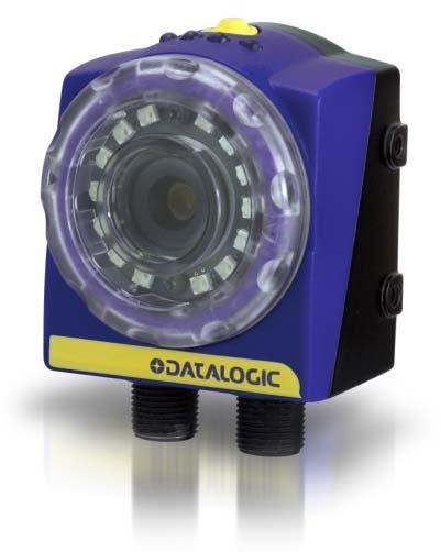
8 DataVS2 Series instruction Manual 2. INSTALLATION 2.1. Sensor overview 2.2. LED description The following system operation LEDs are available on sensor body: LED Number Description Working Color LED 1 Network connection Green LED 2 Digital output 2 Orange LED 3 Digital output 1 Orange LED 4 Power connection Green 2
9 Instruction Manual DataVS2 Series 2.3. Mounting Sensor can be mounted with an angle of 5-7 degrees to the vertical axis of the object; this can help to avoid strong reflections from the object. If a Geometric Pattern Match Tool is included in the Inspection performed by the sensor, we recommend to mount the sensor with a 0 degrees angle to the vertical axis of the object; for further explanation regarding the Geometric Pattern Match, please see Chapter The sensor shall be mounted as close to the object as possible, but within the minimum working distance of 50 mm. Please consider the following points before choosing the working distance: first of all the size of the Field of View (FOV) enhances with the working distance (WD) (see chapter 4.4 for detail). Thus you will need to choose a larger WD to get a larger FOV. But the larger the FOV the lower the resolution of the image. Please note that the working distance should be set in order that the camera can detect the characteristic of the object to recognize with as much clarity as possible. Additionally, the longer the working distance the more susceptible the camera becomes to ambient light. We recommend the use of additional lighting for distances greater than 30 cm to reduce the influence of ambient light. Avoid spilling fluids on the device and make sure it is not exposed to strong vibration. Do not mount the sensor at a position where the object is exposed to direct sun light or strong ambient light. To mount the sensor you need 4 screws, M4 x 6mm. The following image shows mechanical mounting of the sensor by use of the mounting kit (see Chapter 15): 3
10 DataVS2 Series instruction Manual 2.4. Operating distances Working Distance (WD) is the distance from the optical surface of the sensor to the object. The Field Of View (FOV) is the area which is visible for the sensor at a certain working distance. Normally the size of the FOV increases with the working distance. Working distance (mm) DataVS2-12-DE- OR/AOR DataVS2-08-DE- OR/AOR DataVS2-06-DE- OR/AOR DataVS2-16-DE- OR/AOR x x x x x x x x x x x x x x x x x x x x x x x x x x x x x x x x x x x x x Focusing ring In order to focus the area placed by the sensor you should use the transparent focusing ring on the front side of the sensor. Referring to the following picture, you must clockwise rotate the focusing ring in order to focus more distant points; you must anticlockwise rotate the focusing ring in order to focus less distant points. 4

11 Instruction Manual DataVS2 Series 2.6. Electrical connection The sensor has two M12 connectors, X1 and X2 (see paragraphs below). Connect power supply to port X1. To use the sensor without being integrated into the machine environment, you only need to connect PIN2 of Connector X1 to 24 V DC; PIN7 of the connector X1 to Ground. Connector X2 needs to be connected to an Ethernet 100 Mb port of your PC for sensor configuration through the DataVS2 Graphic User Interface. We recommend you to use a crossed Ethernet cable for direct connections between the PC and the sensor; a straight Ethernet cable for connecting the PC and the sensor through a LAN. To ensure proper operation, never exceed device ratings (see Chapter 12 for a complete list) X1 Connector (M12 8-pole): power supply and I/O PIN Description Wire color 1 Digital INPUT White 2 24 V DC Brown 3 Strobe for external illuminator Green (OUTPUT) 4 OUTPUT 1 Yellow 5 OUTPUT 2 Grey 6 OUTPUT 3 Pink 7 GND Blue 8 External trigger (INPUT) Red 5
12 DataVS2 Series instruction Manual X2 Connector (M12 4-pole): Ethernet connectivity PIN Description Wire color 1 Rx+ White/Orange 2 Tx+ White/Green 3 Rx- Orange 4 Tx- Green 2.7. Graphic User Interface installation and start-up The supplied DataVS2 Graphic User Interface needs to be installed on your PC to allow for configuring the sensor Minimum system requirements Make sure your personal computer meets the following minimum requirements to ensure proper interfacing with the system: Component Recommended Minimum Processor(s) Pentium 4 Pentium 4 Operating System Windows XP (Service Pack 3) Window XP (Service Pack 2) Clock frequency >= 2 GHz >= 1.4 GHz RAM 2 GB 1 GB Graphic card RAM 128 MB 128 MB Free hard drive space 60 MB 50 MB(without.NET Framework) Monitor resolution 1280x x768 Besides components listed in the table above, your PC must be equipped with the following hardware and software drivers: CD-ROM drive Installed Ethernet network card and installed driver One free 100 Mbps Ethernet port Note: to install and run DataVS2 Graphic User Interface on Windows XP you need a User Account with Administrator rights DataVS2 Graphic User Interface Installation We recommend closing any programs that are currently running. Then, follow steps below: Insert the supplied CD-ROM into the personal computer drive. After a few seconds, the startup screen is displayed automatically (see picture below). 6

13 Instruction Manual DataVS2 Series Note: If the screen does not appear, launch the installation program manually. Select "Run " from the START menu and type "X:\setup.exe", where "X" is the letter associated with the CD- ROM drive in your system. Select "Install DataVS2 GUI" to start software upload to your hard disk and then simply follow the on-screen instructions. Restart the system to complete installation. 3. SENSOR SETUP 3.1. General overview The DataVS2 is a sensor which takes images of an object. These images are checked by the means of so called Vision Controls with a taught reference image taken from a reference object. With Vision Controls you can check for certain attributes like the contrast of the object surface in comparison with the background or the object width. The DataVS2 Graphic User Interface is needed for sensor adjustment and configuration. It allows the visualization of the images taken by the sensor and to setup inspections. You can always download the most current version of the DataVS2 Graphic User Interface from the following link: The figure below gives you an overview of the DataVS2 Graphic User Interface. All displays of the DataVS2 Graphic User Interface are shown in this overview: 7

14 DataVS2 Series instruction Manual 3.2. Communicating with the sensor Communication with the sensor occurs via the Ethernet network. Two types of connection are possible: direct connection: personal computer is connected directly to device using a "cross cable". Through LAN: use common network (non-cross) cables normally used to connect devices to routing hubs. Note: This network architecture is termed "star" configuration because all network cables are connected to a central HUB. 8


15 Instruction Manual DataVS2 Series It is essential that the IP addresses of personal computer and device be compatible. The Graphic User Interface offers a discovery feature that automatically searches for and locates any sensors in the network and displays their IP address and Subnet Mask information. After selecting the desired sensor, you may proceed to set inspection settings (see the following paragraph) Check PC Network Settings It is essential that the IP addresses of your personal computer are compatible to those of the sensor to successfully set up a communication. Note: You need to have administrator rights established for the present user logged in to follow the next instructions. If this is not the case, please contact your local IT manager for assistance in creating this. If you use a direct connection: From menu START select Control Panel Network Connections LAN Conncetion; Press the right mouse button and select Properties (as shown below); 9

16 DataVS2 Series instruction Manual Select Internet Protocol (TCP/IP) then click the Properties button (as shown below); Select Use the following IP Address option; Enter the following: IP ADDRESS: ; SUBNET MASK: ; Note: no entries for Default Gateway or Use the following DNS Server Address are necessaries. Click OK to close the dialog TCP/IP properties; then click OK at the LAN Properties dialog. If you are connected to the sensor through a routing device you should first verify if the network hosts a DHCP server. If the network hosts a DHCP Server From menu START select Control Panel Network Connections LAN Connections; Press the right mouse button and select Properties; Select Internet Protocol (TCP/IP) then click Properties button again; Finally select Obtain an IP Address automatically (as shown below). 10

17 Instruction Manual DataVS2 Series Depending on the settings of your PC the current state of the network connection is shown in the task bar. Please wait until the network connection is established before you try to connect to your sensor. If the network doesn t host a DHCP Server: Please contact your local IT manager for assigning an IP Address to your PC; Follow the instructions for direct connection configuration (pag. 8) Set up Communication To setup a communication between sensor and the DataVS2 GUI please follow this list of instructions: Connect PIN2 of Connector X1 to 24 V DC; connect PIN 7 of Connector X1 to Ground (see Chapter 2 for electrical connection description). Disconnect any Ethernet cable connected to your PC Connect Connector X2 to Ethernet 100 port of the PC Start the DataVS2 Graphic User Interface Select in STEP1: Online, then Find sensor (see picture below). The software now shows all found sensors at the right side of the screen, in the CONTROL PANEL. Select which sensor on the network to connect to in order to establish communication. 11


18 DataVS2 Series instruction Manual Click the Connect button and the software will try to establish a connection with the sensor: if success, a message will appear, displaying the current connected sensor Model Type and the related Firmware version. 12


19 Instruction Manual DataVS2 Series You have successfully established communication and may proceed to set up your inspection. Note: Find sensor is a discovery feature that automatically searches for and locates any sensors in the network and displays their IP addresses and Subnet Mask information. It is based on Broadcast protocol and can work only inside a Local Area Network Set up Sensor IP-Address As a default all sensors have this IP-Address: The DataVS2 Graphic User Interface allows to set up an individual IP-Address for every sensor. Please follow these steps if you want to change the IP-Address: Connect to the sensor as described in the paragraph above. Select the menu Sensor from the menu bar and select the entry Settings. The DataVS2 GUI will open a dialog displaying different Tabs for Sensor Parameters configuration. Select the Tab Network Settings: On the left side of the Network Settings Tab you will see the current sensor configuration: o The current name of the sensor which can be 4 character long o The current IP-Address of the sensor o The current Subnet Mask 13

20 DataVS2 Series instruction Manual The right side of the Network Settings Tab will allow you to change the Name, the IP-Address and the Subnet Mask of the sensor. Please mind these notes: o o o The name can only be 4 characters long. All characters shall be plain ASCII. Option DHCP enabled will launch the DHCP client process running on your sensor. After power off and restart the sensor IP-Address will automatically be configured by the DHCP Server process running on your LAN. If your LAN doesn t host a DHCP server process or if you want to assign the sensor a static IP-Address, please choose the option DHCP disabled and insert a valid IP- Address and Subnet Mask. You may also press button Suggested IP : the DataVS2 GUI will suggest you a valid IP-Address for the sensor. o The new IP-Address shall differ from those your PC is currently using. Otherwise the sensor cannot be connected anymore with the PC. o The new IP-Address shall not be set to Otherwise communication with the o o sensor will be impossible. The new Subnet Mask shall not be set to Otherwise communication with the sensor will be impossible. The new IP-Address shall not be set to This IP-Address is normally used for loopback communications between processes running on the same PC. After you have clicked Apply changes button the sensor will store the new configuration. The DataVS2 GUI will disconnect from sensor. The new IP-Address will be set active after the next POWER UP of the sensor. The old settings remain active until next POWER UP. An alternative way to change the sensor IP-Address is the following one. You can use it when no communication is established between sensor and PC: Select Online button in STEP1. A connection mode popup window will open. Select Find sensor. DataVS2 GUI searches for all connected sensors and shows all found sensors in the so called CONTROL PANEL. Select from the list the sensor whose IP-Address is to change. Select Configuration button. The following window will appear: In the top section you find the current IP-Address of the PC. In the middle you find a suggestion on the network settings of the sensor. In the lower section you find the input boxes for the network settings (use arrow keys, numerical entries and the scroll of the mouse-wheel). After clicking Ok the IP-Address will be sent to and stored by the sensor. The new IP-Address will not become active until the next power-up of the sensor. 14
21 Instruction Manual DataVS2 Series Troubleshooting If the connection between the sensor and the software does not work immediately, please check the following issues: 1. Check the wiring of the sensor to the power supply and the communication cable. 2. Check the connection as described in Chapter Exit the Software and restart it again. 4. If you have a Firewall running on your PC: please check if the TCP port 5423 is enabled and not used by any other program. If not enabled, please enable this port. 5. Run the Recovery mode (see Chapter 10 in this manual) and follow the described steps to verify the sensor works with the initial parameters. 6. After you have done this, exit the Software and restart both the sensor and the Software again. If the sensor still not work, try to connect another sensor with the PC to verify if the sensor interface has been damaged Updating Software Every sensor comes with the most current DataVS2 GUI software available. Datalogic will supply updates to this software on its website to provide you with enhanced features and new functions. If you want to update the DataVS2 GUI software simply follow the instructions below: Uninstall the software (if installed on your PC) using Microsoft Windows Software dialog Press the Windows START button Select CONTROL PANEL System Software Select DataVS2 GUI out of the list of installed software and press the Delete button shown at the right side of the screen: Windows now uninstalls the DataVS2 GUI software Note: images and projects are not deleted with this procedure. Download the new software version from Datalogic website, if not already done Extract the installation files from the zip package Select the folder where you saved the downloaded files and extract them; double click the DataVS2GUI.msi : the update of the DataVS2 GUI software is now installed General sensor settings The following table displays all the sensor parameters that can be configured through the DataVS2 GUI software. The Firmware Version column represents for each parameter all the sensor firmware versions that are able to manage the corresponding functionality; as an example, the DHCP functionality is not managed by 0.0.X firmware versions. This means that when the DataVS2 GUI software is connected to a sensor running a 0.0.X firmware version the DHCP controls will be disabled. The Factory Settings represent for each parameter the default value that you will find on your sensor at the first connection. The values column contains all the admitted values for the corresponding parameter. The DataVS2 OR and DataVS2 AOR columns refer to the sensor Model Type and are checked depending on the availability of the parameter in the selected Model. 15

22 DataVS2 Series instruction Manual Parameter Firmware version Factory settings Values Sensor name 0.0.X DataVS 4 ASCII characters for 0.0.X versions 20 UTF-8; characters for ST2.X.Y versions Current running Inspection Number of Inspections stored on the sensor 0.0.X 1 [1-8] for 0.0.X versions [1-20]: for ST2.X.Y versions 0.0.X 1 [1-8] for 0.0.X versions [1-20]: for ST2.X.Y versions DataV S2 OR IP Address 0.0.X Subnet Mask 0.0.X Insp Switching 0.0.X 10ms [10-100] ms pulse duration Current Insp Switching protocol ST2.1.X Std Std Adv Teach Adv + Teach DHCP ST2.1.X Disabled Enabled Disabled ClockMode ST2.1.X 180MHz OR 180MHz 480MHz AOR 480MHz DataV S2 AOR To configure sensor settings the DataVS2 GUI software make you available a special window, so called Sensor Settings, that you can open from the Sensor menu item. The functionalities available in Sensor Settings window are organized on 4 tabs, explained in the following paragraphs Network Settings This panel allows you to setup the sensor Ethernet communication parameters. The window is organized into two areas: Current Configuration, representing the current Ethernet configuration on the sensor and Desired Configuration. 16
23 Instruction Manual DataVS2 Series Parameter Description DataVS2 OR Sensor name The sensor current and desired name; to change the current sensor name insert the desired one and press the Apply Changes button. Note: the sensor name must be a non empty string composed by 20 characters at most. Note: changing this value will require a sensor restart. DHCP Disables the DHCP function. disabled Note: this control is disabled for sensors running a 0.0.X firmware versions DHCP enabled IP Address Subnet Mask Suggested IP Apply Changes Note: changing this value will require a sensor restart. Enables the DHCP function. With the DHCP function enabled the sensor is configured with a dynamic IP Address retrieved by a DHCP server installed on your LAN. If no DHCP server is running on your network the sensor will restore the static IP Address after a 4 minutes timeout occurred. With DHCP enabled you won t have to configure the sensor IP Address anymore. Note: this control is disabled for sensors running a 0.0.X firmware versions. Note: DHCP function will enable the DHCOP Client process on the sensor. Be sure your network is running a DHCP server before enabling this function on the sensor, otherwise the sensor will not be able to get a dynamic IP Address. Note: changing this value will require a sensor restart. The current sensor IP Address. Use this field to manually change the sensor IP Address. Note: this function is disabled when the DHCP option is enabled. The current sensor Subnet Mask. Use this field to manually change the sensor s Subnet Mask. Note: this function is disabled when the DHCP option is enabled. After pressing this button the DataVS2 GUI will calculate a valid, static IP Address for the sensor and display it in the two fields above the button. We suggest you to use this function when you need to change the IP Address of the sensor. Note: this function is disabled when the DHCP option is enabled. Press this button to apply the Desired Configuration on the sensor. Note: After applying changes on the sensor DataVS2 GUI will disconnect from the sensor and you will need to power-restart the sensor. DataVS2 AOR 17
24 DataVS2 Series instruction Manual Memory Status This panel allows you for sensor memory configuration. It is also used for Opening Inspection from sensor and Saving Inspection on sensor Tasks. Parameter Description DataVS2 OR DataVS2 AOR Slot column The sensor s memory Slot. The sensor s memory dedicated to Inspection storage is organized in Slots: a Slot is a sensor memory area where you can store an Inspection. From ST2.1.X firmware version sensor makes you available 20 memory Slots. Older firmware versions make available only 8 memory slots. Inspection name column The name of the Inspection stored in the corresponding memory slot. Slot Status Indicates if a Slot is empty (green) or not (red) column Running column Indicates the current running Inspection on the sensor. Note: only one Inspection per time can be checked as running. Note: if an empty Slot is checked as Running, the sensor is in IDLE state, i.e. it doesn t execute any Inspection name text box Load Images radio button Don t load images radio button Inspection The name of the Inspection to be saved on the sensor. Note: this field is enabled only when performing a Saving Inspection on sensor Task. Enabled only when performing a Load Inspection from sensor Task. If images are present on the sensor (stored during Inspection execution) select this option to load images together with Inspection on DataVS2 GUI Enabled only when performing a Load Inspection from sensor Task. If images are present on the sensor (stored during Inspection execution) select this option to avoid loading images together with Inspection on DataVS2 GUI Images not When performing a Load Inspection from sensor present radio Task, if no images are present on the sensor this option button is selected. Change Press this button to change the current running 18

25 Instruction Manual DataVS2 Series Inspection Open Inspection Save Inspection Erase Selected Erase all Inspection on the sensor. After pressing this button the Inspection corresponding to the selected table row will be selected as the current running one. Note: the selected Slot is highlighted with blue color. Press this button to Load an Inspection from Sensor. After pressing this button the Inspection corresponding to the selected row will be loaded and shown by the DataVS2 GUI. Note: the selected Slot is highlighted with blue color. Press this button to perform a Save Inspection on sensor Task. After pressing this button the current Inspection will be saved in the selected memory slot. Note: the selected Slot is highlighted with blue color. Clear the selected memory Slot; the Inspection will be deleted. Note: the selected Slot is highlighted with blue color. Clear all the memory Slot; all the Inspection currently stored on the sensor will be deleted Firmware Update This panel allows you to perform a Firmware Update operation. 19
26 DataVS2 Series instruction Manual Parameter Description DataVS2 OR Current The version of the firmware currently running on the running connected sensor firmware Choose File Press this button to select the desired firmware file to upload on the sensor. A file dialog will be opened allowing you to choose the desired firmware file stored on your PC. Available firmware files can have two different extensions: sfw2: denotes a STD.2.1.X firmware file, updated to the last revision sfw: denotes a 0.0.X firmware file, an older version. After selecting the desired firmware file and pressing the OK button from the File dialog window, the selected firmware version will be displayed in the Update firmware Desired Firmware field. Press this button to update firmware on the connected sensor. Two are the possible type of firmware update that can be performed: firmware upgrade: (i.e. a newer firmware version is uploaded on the sensor) all the Inspections stored on the sensor will be updated according to the new firmware. Note: updating firmware from 0.0.X to STD.2.1.X will require to power-restart on the sensor. firmware downgrade:(i.e. an older firmware version is uploaded on the sensor) all the Inspections stored on the sensor will be deleted. Note: if this button is disabled the selected firmware is not compatible with the connected sensor because of an hardware version incompatibility. In this case, please, select a different firmware. Note: After updating firmware on the sensor DataVS2 GUI will disconnect from the sensor and you will need to power-restart the sensor. DataVS2 AOR General Settings 20
27 Instruction Manual DataVS2 Series Parameter Description DataVS2 OR Sensor Set the connected sensor clock frequency to 480MHz. Speed Turbo Note: this function is enabled only for DataVS2 AOR Sensor Speed Normal Standard Protocol Expert Protocol Expert protocol plus Teach In Teach In Digital pulses duration Model Type. Set the connected sensor clock frequency to 180MHz. Note: this function is enabled only for DataVS2 AOR Model Type. Enables the digital Inspection selection function and select the Standard Protocol as the current digital Inspection selection protocol Enables the digital Inspection selection function and select the Expert Protocol as the current digital Inspection selection protocol Enables the digital Inspection selection function, select the Expert Protocol as the current digital Inspection selection protocol and enables the digital Teach In function Enables the digital Teach In function. Disables the digital Inspection selection function. Represents the minimum duration required for digital I/O pulses used in Inspection switching protocol (see Chapter 6). DataVS2 AOR 4. INSPECTION SETUP To operate as a stand-alone device the DataVS2 Vision Sensor requires a preliminary configuration procedure. The result is a so called Inspection. The term Inspection represents a certain set of operations the sensor performs in order to check the features of an object. If all features comply with certain specification configured during Inspection setup, the Inspection result will be SUCCESS, otherwise the Inspection result will be FAILURE. The DataVS2 GUI software will lead you through three STEPS needed for building an Inspection. Each STEP is identified by a number. When a STEP is active the DataVS2 GUI will display it in a bright red highlight; inactive STEPS are shown with blue color. If you need to change backwards to any other STEP during setup procedure you can do so by clicking the triangle of the STEP you want to change to. After clicking it, this STEP will be highlighted. STEP1: Image Setup. Allows you to choose operation mode, create or load an Inspection and setup image acquisition properties. STEP2: Teach. Allows you to insert Locators, Controls and configure Output behavior. STEP3: Run. Allows you to test the Inspection and finally run it on the sensor. 21

28 DataVS2 Series instruction Manual 4.1. General considerations A successful Inspection is based on a reference image with good quality, as the image of each object to be inspected will be compared with it. The object features you want to inspect should be clearly visible in the reference image. Because of this reason you should assure the reference image is characterized by the following properties: assure the reference image is in focus, which means it has sharp clear contours assure the reference image is characterized by high contrast between the target object and the background. Following a few tips to facilitate correct configuration of the sensor: determine which product feature you want to be monitored provide correct, even lighting minimize the influence of the ambient light on the target accurately choose the Controls to be used for the Inspection in order to provide the best result accurately setup Control parameters and tolerances: some features may be hard to identify with low tolerances. Mostly a "good" part never matches 100% with the reference image taught. Position offset or light level fluctuations can affect the match score. Any "bad" part should differ from a "good" part in as many characteristics as possible allowing for a large gap between the match score of the good and the bad parts. We recommend trying several good parts while testing your application as well as several bad parts. Be sure to consider eventual changes in lighting conditions and position as well when you choose the appropriate Desired value. In the following paragraphs we discuss individual STEPS with their options and selectable parameters STEP 1: IMAGE SETUP During this first step, the DataVS2 GUI allows you to perform the following operation: Select the operation mode of DataVS2 GUI, either Online or Offline (Simulator mode). Select the current Task: create a new inspection or to change an existing one. Setup the basic settings of the Vision Sensor while in Online mode. Select the reference image you want to build your inspection with Quick Walkthrough STEP 1 Note: please, follow steps described in Chapter 3, Setup Communication, before proceeding with the following steps. Select in STEP1 Online ; the DataVS2 GUI software will now popup the Connection Mode Selection window. Select Find sensor. The software now shows all found sensors at the right side of the screen, in the CONTROL PANEL. Select which sensor on the network to connect to in order to establish communication. 22
29 Instruction Manual DataVS2 Series Click the Connect button and the software will try to establish a connection with the sensor: if success, a message will appear, displaying the current connected sensor Model Type and the related Firmware version. Note: After the connection to the sensor is established, if no Task is currently selected (STEP 2 and STEP 3 triangles are disabled and displayed with grey colors), the DataVS2 GUI automatically select a New Inspection Task and starts displaying images acquired by the sensor in the IMAGE PANEL. If a Task is already selected in STEP 1, from the drop-down menu below the Select a Task label choose New Inspection ; the DataVS2 GUI will now popup you the Model Type Selection window: choose the same sensor Model as your sensor one and press Ok button. The DataVS2 GUI will now display Basic Settings parameters at the right side of the main window, in the CONTROL PANEL. Set Internal Illuminator to On. Press Auto exposure button and change Gain value till the image has a good contrast and brightness level. Manually adjust the focus of the sensor by means of the sensor s front side focus ring until a sharp picture is seen. If the current image is sharp but have poor contrast you should repeat the previous steps. Click Set Reference Image button; now you have selected the current displayed image as reference for your Inspection Operation Modes The DataVS2 GUI offers two different modes of operation: Online mode, with active sensor connection; Offline mode, in which you may process images previously acquired and stored on your PC. This operation mode lets you simulate an Inspection using previously stored images, thus you can test or configure an Inspection without a connected sensor. It also allows to focus attention on determining the best suited control parameters as you will not have to cope with a constant flow of images. To choose the mode you want, click the appropriate button. Note: STEP 1 has different "work flows" in offline and online mode as described in the next sections. 23


30 DataVS2 Series instruction Manual Establish Connection with sensor Online mode only If you have chosen Online mode the software will pop-up this window: Parameter Description DataVS2 OR Find sensor DataVS2 GUI searches for any connected sensor and display them in a list in the CONTROL PANEL Connect to DataVS2 GUI will establish a connection with the sensor addresses by the displayed IP number DataVS2 AOR If you have selected FIND SENSOR the software will first show a window with a progress bar, if there were any connected sensors it will show this screen in the CONTROL PANEL at the right side of the main window: The Control panel shows all sensors found by the Find sensor function. For each sensor the panels shows: the IP address of this sensors the subnet mask of this sensor an indication whether a connection can be created (row highlighted in green color) or not (row highlighted in red color) a checkbox, representing the selected sensor for the connection. If more sensors are shown in the list you can select the sensor you want to connect by the means of the checkbox in the last column. Once you have selected the sensor you want to connect to, press the Connect button. Note: when sensor row is highlighted with red color, the sensor is not reachable by the DataVS2 GUI software. You may use the Configure button to change its IP Address and Subnet Mask, according to your current LAN Network configuration, see Chapter


31 Instruction Manual DataVS2 Series Task Selection The next step for both Online and Offline modes will be selecting a task. Click the drop-down menu below Select a Task label in order to select the desired task. Parameter Description DataVS2 OR DataVS2 AOR New Creates a New Inspection. Inspection Open Loads an existing Inspection from the PC Inspection from PC Online mode only: Open Inspection from sensor Download an existing Inspection from the connected sensor. If you choose New Inspection in Offline mode the DataVS2 GUI will first popup the Model Type Selection window; this will allow you to choose the sensor model you want to simulate. The DataVS2 GUI allows you to work with all available sensor model types. We suggest you to always choose the same model type as your sensor one. The DataVS2 GUI will not allow to save on the connected sensor an Inspection configured for a different Model Type. After choosing the Model Type, a File Dialog will be opened by the DataVS2 GUI: this allows you to load the images you want to integrate into your inspection. You may load more than one image. After you have loaded these images their thumbnails are shown at the IMAGES BUFFER. You can select the current image by simply clicking the thumbnail. If you want to load more images you can do so by clicking the "Load Image" button in the CONTROL PANEL. Note: the DataVS2 GUI will allow you to work only with images previously acquired with the sensor. The first time you startup the DataVS2 GUI you will find some sample images inside the Images folder in the Program Installation directory. Once you have selected your reference image, click the "Set Reference Image" button to confirm. If you choose "Open Inspection from PC" the DataVS2 GUI opens a File Dialog. This dialog shows the list of inspections stored on the PC. Choose one of them and press the Open button. 25


32 DataVS2 Series instruction Manual If you choose "Open Inspection from sensor" the DataVS2 GUI opens a dialog. This dialog shows the list of inspections stored on the sensor. Choose one of them and press the Open button. 26
33 Instruction Manual DataVS2 Series Basic Settings Online Mode only After you have created a "New Inspection" while in Online mode, the CONTROL PANEL will display you the Basic Settings of the sensor. Before changing the Basic Settings parameters, press the Start Live button: in this way you will be able to see how changes will affect images acquired by the sensor. 27
34 DataVS2 Series instruction Manual Parameter Description Default DataVS2 OR DataVS2 AOR Exposure Time Changing the Exposure Time value will affect the image brightness. The higher the Exposure time, the brighter the image will be 3.0 ms Auto exposure Gain Image Resolution External Illuminator Internal Illuminator Start / Stop Live Live Status the image acquired by the sensor. Pressing the Auto exposure button the sensor will automatically setup the best Exposure Time value depending on the current ambient light conditions Changing the Gain value will affect the image contrast. The higher the Gain value, the greater the contrast between black and white values will be; grey colors will be reduced. Represents the pixel resolution currently used by the sensor; this parameter affects the Image dimension in pixel. Three are possible image resolution: High: 640x480 pixels Medium: 320x240 pixels Low: 160x120 pixels The lower the resolution is the faster the Image acquisition phase (and the Inspection execution cycle on the sensor) will be. Changing the Image Resolution will cause a New Inspection creation. The DataVS2 GUI software doesn t allow you to work with different image resolution at the same time. Note: using a Low Image resolution may affect the robustness of the Control execution, because of lack of Information in the image. Avoid Low Image resolution usage with measuring Controls (Position, Edge Count and Width). Enables or disables external illuminator (if any) connected to Strobe PIN of M12-8 pole connector Enables or disables integrated illuminator; three are possible values: Off: illuminator is disabled On: illuminator is enabled and works in normal mode Power: illuminator is enabled and works in power mode. The light is more strong. We suggest you to lower Exposure Time value when using internal illuminator in power mode, otherwise you will have too much brightness in the image. Starts or Stops LIVE MODE. In Live Mode the sensor acquires images and send them to the DataVS2 GUI. Indicates if Live mode is active (Bright Green) or not (Dark Green). 1.0 High Off On Disconnect Disconnect the DataVS2 GUI from the sensor. When you have selected the appropriate set of Basic parameters, continue. 28


35 Instruction Manual DataVS2 Series Trigger Selection Generally speaking, the term Trigger represents a signal generated by an event that triggers another event. In our instance, the trigger is a signal generated by a device that triggers image acquisition. When the sensor is used to inspect moving objects, it is important to ensure that the object is inside the shot area at the precise instant the image is captured for processing. To this end, the system offers three types of triggers for the inspection configuration process: Continuous: default trigger. System will acquire images at the fastest rate possible. A new image will be acquired as soon as the last one was processed. Hardware Rising: uses an external trigger signal. A new image will be acquired as soon as there is a rising edge (from 0 to 24V) at PIN8. Hardware Falling: uses an external trigger signal. A new image will be acquired as soon as there is a falling edge (from 24 to 0V) at PIN8. When the trigger mode is set to Hardware, it is possible to setup a special time interval, a so called Trigger Delay, used by the sensor to postpone the image acquisition of a well defined time interval after the trigger event has been received. We recommend using an Hardware trigger when the sensor is used integrated in a machine environment. It is absolutely necessary to use an Hardware trigger to inspect any moving object; it is important to ensure that the object is inside the field of view of the sensor at the moment the sensor acquires the image. Select the type of trigger used to define inspection time instants; different panels are shown for Trigger configuration depending on the current operation mode, Online or Offline, as shown in the table below. 29

 at PIN 8. Hardware Falling: use external hardware trigger e.g. a sensor. A new image will be acquired as soon as there Trigger Delay is a falling edge (24 V to 0 V) at PIN 8.")
36 DataVS2 Series instruction Manual Offline mode Trigger configuration Online mode Trigger configuration The following table contains a brief description of the parameters used to configure the Trigger options. Parameter Description Default DataVS2 OR DataVS2 AOR Trigger Mode Represents the type of trigger used to Continuous define Inspection time instants. Three are the available Trigger Modes: Continuous: default trigger. Sensor will acquire images at fastest rate possible. A new image will be acquired as soon as the last one was processed. Hardware Rising: use external hardware trigger e.g. a sensor. A new image will be acquired as soon as there is a rising edge ( 0 to 24 V) at PIN 8. Hardware Falling: use external hardware trigger e.g. a sensor. A new image will be acquired as soon as there Trigger Delay is a falling edge (24 V to 0 V) at PIN 8. Represents the time interval (in milliseconds) between the instant when the external trigger signal occurs and the next image is captured by the sensor. Trigger Delay control is active and selectable only when Trigger Mode is set to Hardware. Disabled Once you have selected the desired type of trigger, you may test it by starting the LIVE MODE and verifying images acquired by the sensor. 30


37 Instruction Manual DataVS2 Series Reference Image setup Finally you have to select the reference image. By clicking the Set Reference Image button you choose the "Master Image" which will be the base of your Inspection STEP 2: TEACH After settings your Reference Image you may now proceed with STEP 2. The following operation are available in this STEP: Inserting a Locator Tool allowing the sensor to find the object inside the image Inserting Control Tools allowing the sensor to check the object attributes Configuring the Outputs Quick Walkthrough STEP 2 Click on the drop-down menu below the Select Control label and choose a Control from the list shown based on the inspection needed. Note: The Controls pool changes depending on the current Selected sensor Model. For a complete list of the sensor Models, please refer to Chapter 5.2. Once a Control has been selected, drag the Controls icon over the image to the position of the desired inspection. Click the Controls icon (mouse pointer) to anchor its position. Now you see a so called "Region of Interest" (ROI) frame (see picture below) inside the image: Place the cursor over any of the 4 ROI borders, a 4 arrow head cursor should appear. Click and hold while dragging the Region of Interest frame to adjust the overall position in the image. 31


38 DataVS2 Series instruction Manual Place the cursor over any of the 8 ROI anchors; click and hold while dragging the anchor. Now resize the frame so that the object area to be inspected is fully covered as shown below: The DataVS2 GUI software will now display the parameters of the current Control, at the right side of the screen in the CONTROL PANEL. Change these parameters as needed to create the most reliable Control performance. The online help on lower right side of the screen provides information to each parameters and how to use this tools. If you want to insert more Controls you have to start with "Select Control" again. Once all the Controls have been created and setup, click the "Output Setup" button to configure sensor s outputs. The DataVS2 GUI software will now display the "Output Configuration" settings for the three available outputs. For each of the three Output Tabs in the CONTROL PANEL choose the appropriate Output Mode configuration by selecting the checkbox corresponding to the desired value. Above Output Mode tabs, the overall Output duration and Output delay can be setup. Once all the outputs have been created and setup, click on the "Test" button directly under the "Run Settings" button and go on with STEP 3. 32

39 Instruction Manual DataVS2 Series Locator Selection A Locator is a special Tool which searches inside the whole image for a certain attribute e.g. a grey value edge or a pattern and determines its position. Once the position has been calculated it is used as the relative reference system for all other Controls included in the same Inspection. If the locator has not found any position in the current image all other Controls in the Inspection will not be calculated and their result will be FAILURE. Note: If you move your mouse cursor into the IMAGE PANEL after you have selected a locator form the pull-down menu under the Select Locator label, it will change appearance; it will show the icon of the Locator Tool as shown the menu. Note: There can at most one locator in every Inspection. Parameter Description DataVS2 OR DataVS2 AOR NONE No Locator is used in the Inspection Position Locates the position of an edge in pixels. The edge is found searching along a direction passing for the ROI center Pattern Match Gmc Pattern Match Searches for a pattern inside the ROI; the pattern template is learned in Teach phase (STEP 2). The pattern to be found must have the same orientation of the template one. Searches for a pattern inside the ROI; the pattern template is learned in Teach phase (STEP 2). The pattern to be found may have different orientation degree than the template one Note: After inserting a Locator it can happen that all your other Controls are not visible in the IMAGE PANEL and DataVS2 GUI only displays the Locator ROI (with red borders). This means that the Locator Tool didn t find a pattern or a good edge. Please, change the position of the Locator ROI or adjust the Locator parameters in order to make the Locator find a good target; as soon as the Locator is OK again all other control ROIs will be displayed Control Selection Select the Control you want to add to the current Inspection by the means of the pull-down menu. If you want to add more than one Control to your Inspection you are allowed to do so up to a maximum of 25 Controls. Note: If you move your mouse cursor into the IMAGE PANEL after you have selected a locator form the pulldown menu under the Select Control label, it will change appearance; it will show the icon of the Control Tool as shown the menu. Note: Please take into account that the more Controls an Inspection has the higher the processing time for the Inspection. 33
40 DataVS2 Series instruction Manual Parameter Description DataVS2 OR DataVS2 AOR Brightness Calculates the average intensity of pixels inside the ROI Contrast Calculates the ratio of the highest to the darkest pixels inside the ROI Contour Searches for a shape inside the ROI; the shape template Match is learned in Teach phase (STEP 2) Edge Count Counts for the number of edges inside the ROI along a searching direction passing for the ROI center Width Measures the distance between two edges in pixels Pattern Searches for a pattern inside the ROI; the pattern Match template is learned in Teach phase (STEP 2). The pattern to be found must have the same orientation of the template one. Position Locates the position of an edge in pixels. The edge is found searching along a direction passing for the ROI center Once selected you have to position your Control in the reference image. This is done graphically by positioning and sizing its ROI inside the working area. After you have selected a Control, the CONTROL PANEL displays the default parameters for this Control. To adapt the parameters, use the graphical controls provided such as sliders and checkboxes. The calculated result of a Control is indicated by the Status indicator turning green or red; the frame of the ROI shown inside the IMAGE PANEL will be displayed in the same color as the status indicator Output Setup Once you click the Output Setup button, the CONTROL PANEL allows you to configuring sensor s outputs. You can setup the desired output configuration for all the three digital outputs: by default they are disabled. 34
41 Instruction Manual DataVS2 Series Parameter Description Default DataVS2 OR DataVS2 AOR Mode Defines the output configuration for this Disabled Output by associating a certain logical result to this output. Negative Logic If you select Negative Logic the output will be low when the Control result is success. In default settings the output will be high when Disabled Output Duration the Control result is success Determines the output duration in milliseconds. The output will retain its last value over the duration time. Duration is 10 ms per default; with this configuration all outputs will maintain their values for 10 ms after an Inspection result is available. When the Output duration is 0 ms outputs maintain their state until the next result is available. Note: changing Output Duration will affect all three outputs Output Delay Determines how long the output should wait before displaying the last result acquired. Delay is 0 ms per default thus the outputs are switching immediately after an inspection result is available. If the Inspection execution time exceeds the delay interval the sensor goes in ERROR signaling: you can see the ERROR message by setting one of the Output Mode to ERROR. This kind of ERROR state doesn t stop the sensor execution. Note: when testing Inspection in RUN mode, with Statistics enabled, on the DataVS2 GUI the Output Delay time out situation is displayed in STATISTICS AND TIMINGS Panel. Note: changing Output Delay will affect all three outputs 10 ms 0 ms Note: be sure the sum of delay time and duration time is always considerably less than the time period between two parts to be inspected. If you infringe this rule the sensor is not able to give a result for every part. 35
42 DataVS2 Series instruction Manual The following table contains an ordered description of all available Output Modes. Parameter Description DataVS2 OR DISABLED The Output is disabled; the digital value is always LOW (or HIGH with Negative Logic flag checked) PART The Output is associated to the result of the Locator (if present); DETECT if the result of the Locator is success, the output is HIGH, otherwise the output is LOW. Note: if the Inspection doesn t contain any Locator this Output Mode value is hidden. Note: this output mode is not present in DataVS2 AOR model, as you can use the Logical Tools in order to realize the same functionality. PART PASS The Output is associated to the logical AND of the Controls currently present in the Inspection; if the result of each of the Controls is success the output is HIGH, otherwise the output is LOW. Note: this output mode is not present in DataVS2 AOR model, as you can use the Logical Tools in order to realize the same functionality. PART FAIL The Output is associated to the logical NAND of the Controls currently present in the Inspection; if the result of at least one of the Controls is failure the output is HIGH, otherwise the output is LOW. Note: this output mode is not present in DataVS2 AOR model, as you can use the Logical Tools in order to realize the same CONTROL RESULT LOGICAL TOOL RESULT BUSY- READY ERROR TOGGLE functionality. The output is associated to the logical result of the Control corresponding to the selected row, if the Control result is success the output status is HIGH, otherwise the output status is LOW. The output is associated to the logical result of the Logical Tool corresponding to the selected row, if the Control result is success the output status is HIGH, otherwise the output status is LOW. In this configuration the output maintain the HIGH value for all the time interval corresponding to the Inspection execution time; as soon as the result is available and the Inspection execution cycle is completed, the output value goes LOW. Note: this output mode is not displayed by the DataVS2 GUI when in RUN mode. In this configuration the output goes HIGH when an ERROR occurred on the sensor; three are the main ERROR situation signaled by the sensor: a software crash occurred during Inspection execution: in this situation the sensor is blocked and need to be restarted (by cycle-powering it). an output delay time out: in this situation the execution time has exceeded the delay time setup by the user; the sensor is not blocked after an output delay time out occurred. a trigger delay error: in this situation the sensor has received a trigger input for the next image acquisition when the previous execution cycle is not completed. The sensor is not blocked after a trigger delay error occurred Note: this output mode is not displayed by the DataVS2 GUI when in RUN mode. In this configuration the output change level after every Inspection is executed on the sensor. There is not relationship with the Inspection result. After every inspection execution the status of the output configured as TOGGLE switches from 0 to 1 and vice versa. Note: this output mode is not displayed by the DataVS2 GUI when in RUN mode. DataVS2 AOR 36
 moving on a conveyor belt: part C is not ok. Every 2500 milliseconds (ms) a new part has to be inspected. We assume an execution time of 500 ms.")

43 Instruction Manual DataVS2 Series Example of a Timing Diagram The following diagram displays an example of Output timing and signals. Let s assume we shall test 4 parts (A, B, C, D) moving on a conveyor belt: part C is not ok. Every 2500 milliseconds (ms) a new part has to be inspected. We assume an execution time of 500 ms. Output Delay is set to 0 ms. The Output Duration is set to 1000 ms. Output Modes are connected according to the following description: Output 1: part OK Output 2: Toggle Output 3: Busy-Ready Following the explanation of the timing diagram displayed in the picture above: The sequence for the trigger signal (at the top of the diagram) shows the trigger signal received by the sensor; in this example we assume the inspection execution starts with the rising flank of the trigger (Trigger Mode is set to Hardware Rising). The Busy-Ready Output goes HIGH when a Trigger input is received. The Busy-ready Output changes to LOW once the Inspection is complete. The black sequence shows the behavior of this output when Output Duration is set to 1000 ms. The red sequence represents the behavior of this output when Output Duration is set to 0 ms; in this case the Busy-Ready signal is set to LOW immediately after an Inspection result is available. Toggle Output is set to HIGH as soon as the Inspection result for part A is available. After the availability of the result for part B the Toggle signal changes to LOW. Every time the Toggle signal changes its state a new Inspection is available. This allow distinguishing between two consecutive inspection results with the same state (e.g. when two adjacent parts are wrong) Output 1 is set to part OK. The black sequence shows the behavior of this output when Output Duration is set to 1000 ms; in this case the output switches to HIGH as soon as a good part is inspected. After staying HIGH for the set Output Duration the state changes back to LOW again. In the diagram above there is no state change for part C, as it is a not good part; the output stays LOW until the result of the next good part is available. The red sequence shows the behavior of this output when Output Duration is set to 0 ms. In this case the output switches to HIGH after part A, a good part, is inspected and does not fall back to LOW until a bad part is found (part C in the diagram above). After going LOW the output stays LOW until a new good part is inspected. 37
44 DataVS2 Series instruction Manual Logical Tool Selection Note: this feature is enabled only when the current Inspection is an DataVS2 AOR model type; you can always check the Model Type value of the current inspection from the INSPECTION EXPLORER panel, see Chapter 13. Working with AOR Models, when you click the Output Setup button, the OUTPUT SETUP TAB will be displayed in the central area of the main window, allowing you for inserting and configuring Logical Tools. Opening the LOGICAL TOOL TAB you will see the list of the Controls currently inserted in the Inspection on the left side and the three digital Outputs on the right, both shown as rectangle boxes. Controls boxes are highlighted with red or green color depending on the logical result of the Control, failure or success. Output boxes are highlighted with grey or yellow color depending on the logical status of the output, low or high. Select the Logical Tool you want to add to the current Inspection by the means of the pull-down menu. Once selected you have to position your Logical Tool in the Logical Tool container. This is done graphically by left-clicking the mouse in the position you want to locate the Logical Tool; after doing that an image will appear representing the logical gate corresponding to the inserted Logical Tool. After selecting the Logical Tool the CONTROL PANEL will display the Logical Tool parameters, represented by the list of all possible Controls that can be connected as inputs to the Logical Tool; the currently connected inputs are shown as checked inputs in the CONTROL PANEL. As soon as the minimum number of Inputs are connected to the Logical Tool you will see its shape changing color and becoming green (SUCCESS) or red (FAILURE) depending on the logical status of the gate. 38

45 Instruction Manual DataVS2 Series Parameter Description DataVS2 OR AND Calculates the logical AND of the Controls connected as inputs OR Calculates the logical OR of the Controls connected as inputs XOR Calculates the logical XOR of the Controls connected as inputs NAND Calculates the logical NAND of the Controls connected as inputs NOR Calculates the logical NOR of the Controls connected as inputs XNOR Calculates the logical XNOR of the Controls connected as inputs NOT Calculates the logical NOT of the Controls connected as inputs MAJORITY Calculates the minimum number of input Controls whose result must be SUCCESS in order to make the Logical Tool result be SUCCESS DataVS2 AOR Once connected the Logical Tool to its inputs you have to connect it to Outputs; to do so, from the Logical Tool container select the output shape you want to connect the Logical Tool to and from the CONTROL PANEL select the Logical Tool row as output Mode. 39


46 DataVS2 Series instruction Manual Note: The maximum number of Inputs that can be connected to a Logical Tool depends on the Logical Tool type; please, refer to Chapter 5.5 for a complete explanation of Logical Tools. Note: If you want to add more than one Logical Tool to your Inspection you are allowed to do so. The maximum number of Tools (Controls, Locators and Logical Tools) that can be inserted in an Inspection is STEP 3: RUN If you have successfully inserted all Controls you need and configured Outputs go on with STEP 3. In this STEP you will be able to: Configure Run Settings for the current Inspection Test your Inspection either Offline or Online Run your Inspection if Online Quick Walkthrough STEP 3 Click on the Run Settings button in STEP 3. The DataVS2 GUI software will display some running options in the CONTROL PANEL. The Images Saving settings can be used to save Inspection related images on the sensor during its execution. The images will be saved in a queue according to a FIFO (First In First Out) policy. The Teach Button setting allow you to enable or disable the teaching behavior of the button integrated on the sensor, see Chapter 7.1. Once the Run Settings have been configured click on the Test button you find directly under the Run Settings one in STEP 3. The DataVS2 GUI will display the Output Status and the Reference Image for the Inspection configured. 40
47 Instruction Manual DataVS2 Series If you are in Offline Mode you can only make an Offline Test: to do so click the Load Image button or click on the IMAGES BUFFER icon in the Tool Bar and select up to 19 images to cycle through for testing. Note: the IMAGES BUFFER stores images into a circular array, according a FIFO policy. After the number of loaded images has reached the maximum array dimension, the next loaded image will overwrite the older one. If you need to load more than 19 images at the same time (and enlarge the array dimension) you can change the IMAGES BUFFER dimension from the OPTIONS Menu. If you are in Online Mode you can perform an Online Test, by clicking the Start button. The DataVS2 GUI software will start loading LIVE images and testing each according to the Inspection settings. Note: for both Online and Offline Test, the Output Status LED shown in the CONTROL PANEL will change according to the settings made for each output. Note: Sensor Outputs are physically disabled in Test mode. To stop an Online test, click the Stop button. To run the Inspection, click on the Run button directly under the Test button in STEP 3. The CONTROL PANEL will display the Run Settings controls. Choose the Statistics and Timings option for the run mode. Now press Start button; if the Inspection has not been saved on the sensor, a dialog box will appear asking you to save the Inspection into one of the available Inspection Slots on the sensor. Each Inspection can be saved with an individual name for easier identification. 41
48 DataVS2 Series instruction Manual Run Settings After clicking the Run Settings button in STEP 3 the CONTROL PANEL will display the following options: Parameter Description Default DataVS2 OR DataVS2 AOR Images Defines the Images Saving behavior on the Disabled Saving sensor during Inspection execution. If enabled the executed images will be saved in a queue according to a FIFO (First In First Out) policy. The sensor can store at most 10 images. Note: you can download and see images saved on sensor by opening the current running Inspection on the sensor. If present, saved images will be downloaded from Teach Button sensor and shown in the IMAGES BUFFER. Enables or disables the teaching behavior of the button integrated on sensor. When enabled, the Teach Button will allow you to change the Reference Image for the current running Inspection without using the DataVS2 GUI software. Enabled The following table displays the possible Images Saving conditions: Parameter Description DataVS2 OR ALL If selected, every Inspected image will be saved on the sensor ON PART If selected, only images corresponding to a Locator DETECT Success will be saved on the sensor. Note: this option is only shown if the current Inspection ON PART PASS ON PART FAIL contains a Locator. If selected, only images corresponding to an Inspection Success (result of all the Controls is Success) will be saved on the sensor. If selected, only images corresponding to an Inspection Failure will be saved on the sensor. DataVS2 AOR Test After clicking the Test button available in STEP 3 the CONTROL PANEL shows: the simulated state of each output (yellow for HIGH, brown for LOW); the current used Test mode (either Offline test or Online test); the Reference Image used for the Inspection. 42
49 Instruction Manual DataVS2 Series Note: Sensor outputs are disabled in Test mode. In Online Test images are acquired by the sensor. Results are calculated by the DataVS2 GUI in both Test modes, Offline and Online. Button Description DataVS2 OR Load Image Offline Mode only: it allows you to add new images to the IMAGES BUFFER which shall be tested according to the current Inspection settings. Start / Stop Online Mode only: sensor will start to acquire images; the Inspection execution is performed on the PC, by the DataVS2 GUI; results are updated. DataVS2 AOR In Offline Mode, an image is tested after you have selected it from the IMAGES BUFFER. The results are displayed in the IMAGE PANEL and the Inspection Explorer is updated Run Run Mode is only accessible in Online Mode. If you click the Run button in STEP 3 the CONTROL PANEL will show: the current state of each output (yellow for HIGH, brown for LOW) the Reference Image used for the current Inspection. Parameter Description DataVS2 OR Graphic The current processed image is sent to the PC and shown in the Enabled IMAGE TAB Statistics The sensor does not send any image to the PC. The DataVS2 and Timings GUI only shows the execution results for each Control, the timing for the current running Inspection phases and the statistics for the current running Inspection. These values may be used to evaluate the performance of the Inspection currently performed by the sensor. Start / Stop After pressing the Start button the DataVS2 GUI will ask you to save the current Inspection into one of the 20 available sensor Slots. Each Inspection can be given an individual name for an easy identification. Note: If your sensor is running a firmware version older than ST.2.1 you will see only 8 memory Slots available for Inspection saving. DataVS2 AOR 43
50 DataVS2 Series instruction Manual Note: Run mode is not accessible if the current sensor Model Type doesn t corresponds to the current Inspection Model Type. In this case you will see the Run button disabled in STEP 3. In order to run your Inspection on the sensor you have to select the sensor s Model Type from the Tool Bar and configure again a New Inspection. The sensor has now been configured and is ready for operating in standalone mode. If the Inspection performance fulfill your needs you can now disconnect the sensor from the DataVS2 GUI software. Press the pull-down menu under the Sensor Menu and select Disconnect from sensor. The sensor will start running as a standalone device. You should also disconnect the Ethernet cable from the sensor Inspection settings The following table lists all the Inspection parameters that you can configure through the DataVS2 GUI software. The Default Value represent for each parameter the default value that the DataVS2 GUI software will set at Inspection creation time. The values column contains all the admitted values for the corresponding parameter. The DataVS2 OR and DataVS2 AOR columns refer to the Inspection Model Type and are checked depending on the availability of the parameter in the selected Model. Parameter Default value Values DataVS2 OR DataVS2 AOR Version Model type OR AOR Name SvsInspection Image resolution 640x480 pixel 640x480 pix 320x240 pix 160x120 pix Exposure Time 3 ms [0,1-100] ms Gain 1 [1-3] Trigger Mode Continuous Continuous Hardware Hardware Trigger Polarity Rising Rising Falling Hardware Trigger Delay 0 ms [0-500] Internal Illuminator Normal Off Normal mode Power mode External Illuminator Off Off On 44
51 Instruction Manual DataVS2 Series Output mode Disabled Disabled Toggle Busy-ready Error Part detect Part pass Part fail Vision Tool dependent Logical Tool dependent Disabled Toggle Busyready Error Part detect Part pass Part fail Output Duration 10 ms [0-1000] ms Disabled Toggle Busyready Error Vision Tool dependent Logical Tool depende nt Output Delay Disabled Disabled [1-1000] ms Output Logic Positive Positive Negative Teach button Enabled Disabled Enabled 5. DATAVS2 EASY GRAPHIC USER INTERFACE After launching the program, the following screen is displayed: Each DataVS2 GUI component is explained separately with detail in the following chapter. 45

52 DataVS2 Series instruction Manual 5.1. DataVS2 GUI Components This chapter describes the following DataVS2 GUI components: Menu Bar Tool Bar Setup Panel Control Panel Image Buffer Image Panel Output Setup Panel Statistics Panel Inspection Explorer Help Panel Status Bar Menu bar The Menu bar groups the main DataVS2 GUI functionalities in 4 different menu items: File: groups Task selection and management functions; Sensor: groups the main sensor options; Options: groups the DataVS2 GUI software options; Help: shortcut to the operation manual and to DataVS2 GUI general informations. Following a description of each menu item. File Parameter Description DataVS2 OR New Inspection Creates a New Inspection. If an Inspection is already opened the DataVS2 GUI software asks for saving before closing it, then it reset panels to the initial condition. Open Inspection Loads an Inspection into the DataVS2 GUI. Two are the possible options: Open inspection from PC: the Inspection to load is stored on the PC Open Inspection from sensor: the Inspection to load is stored in a memory slot of the sensor. If an Inspection is already opened the DataVS2 GUI software asks for saving before closing it, then it reset panels to the initial condition. Save Inspection Save the current Inspection shown by the DataVS2 GUI. Two are the possible options: Save Inspection on PC: the Inspection is saved on a folder chosen by the user on the PC Save Inspection on sensor: the Inspection is saved on a memory slot of the sensor Exit Close the DataVS2 GUI software. If an Inspection is already opened the DataVS2 GUI software asks for saving before closing. DataVS2 AOR 46

53 Instruction Manual DataVS2 Series Sensor Offline Mode Online Mode Parameter Description Operation Mode DataVS2 OR DataVS2 AOR Connect to Establish a connection with sensor Offline sensor through Ethernet Find Searches for and find sensor in a Offline network Disconnect from sensor Disconnect the DataVS2 GUI from the current connected sensor Online Settings Open the Sensor Settings window, Online allowing the user to change general sensor settings and manage firmware update. Options The menu Options displays the following popup window, allowing you to configure DataVS2 GUI options: 47
54 DataVS2 Series instruction Manual Parameter Description DataVS2 OR Language The current selected language in the DataVS2 GUI software. Four are the managed languages: English Italian German French After selecting the desired language, press the Apply button to confirm. Pressing the Cancel button will restore the previous condition. Save Image When saving the Inspection on the PC, if this buffer Images option is enabled, all the images currently present in the Image Buffer will be saved and packaged together with the Inspection on the PC. Note: to see images saved on the PC you will need to open the Inspection in the DataVS2 GUI. Images are saved in a compressed format. Disable Warnings If enabled, warning messages for Pattern Match Tool and Geometric Pattern Match Tool configuration will not be displayed in STEP2. Show all results If enabled all the graphic results of the Geometric Pattern Match Tool are shown when in STEP3. To faster the DataVS2 GUI when in test mode and assure all images are downloaded from sensor we Images buffer dimension: suggest you to disable this flag. The capacity of the Images buffer: the number of images that can be stored at the same time by the image buffer. Apply Apply changes to the DataVS2 GUI Cancel Restore previous options. All changed options will be ignored by the DataVS2 GUI. DataVS2 AOR Help Parameter Description DataVS2 OR DataVS2 AOR Contents Displays the Online Help About Displays information on DataVS2 GUI and connected sensor version (see image below) When the About menu item is pressed the following window is opened: 48

55 Instruction Manual DataVS2 Series 49
56 DataVS2 Series instruction Manual Parameter (from top to bottom) Description DataVS2 OR DataVS2 AOR Software version The DataVS2 GUI software version Product code The DataVS2 GUI software product code Image The DataVS2 GUI integrated simulator version. Processing Library version Note: after connecting to the sensor the DataVS2 GUI compares the simulator version with the current connected sensor version; if they are different a popup message will shown suggesting to update the sensor. Name The name of the current connected sensor. Note: this field is empty in Offline mode Model Type The current connected sensor Model Type. Note: this field is empty in Offline mode IP Address The current connected sensor IP Address. Subnet Mask Address Mac Address Firmware version Core A Firmware version Core B Firmware version Image Processing Library version Silicon Revision Imager Version Hardware revision Note: this field is empty in Offline mode The current connected sensor Subnet Mask Address. Note: this field is empty in Offline mode The current connected sensor MAC Address. Note: this field is empty in Offline mode The current connected sensor firmware version. Note: when Firmware version is different than Simulator version you should update firmware on the sensor. Note: this field is empty in Offline mode The current connected sensor Core A version. Note: this field is empty in Offline mode The current connected sensor Core B version. Note: this field is empty in Offline mode The current connected sensor Image Processing Library version. Note: this field is empty in Offline mode The current connected sensor Silicon Revision. Note: this field is empty in Offline mode The current connected sensor CMOS version. Note: this field is empty in Offline mode The current connected sensor Hardware revision. Note: this field is empty in Offline mode Tool bar Gives quick access to typical functions. It is divided into 8 sections: Section 1: current loaded Inspection Name In this section a textbox allows you for configuring the Name of the current Inspection. Note: when a new Inspection is created a default name is assigned by the DataVS2 GUI, SvsInspection. 50
57 Instruction Manual DataVS2 Series Section 2: functions related to File menu Function (left to right) New Inspection Open Inspection Save Inspection Description Creates a New Inspection. If an Inspection is already opened the DataVS2 GUI software asks for saving before closing it, then it reset panels to the initial condition. Loads an Inspection into the DataVS2 GUI. Two are the possible options: Open inspection from PC: the Inspection to load is stored on the PC Open Inspection from sensor: the Inspection to load is stored in a memory slot of the sensor. If an Inspection is already opened the DataVS2 GUI software asks for saving before closing it, then it reset panels to the initial condition. Save the current Inspection shown by the DataVS2 GUI. Two are the possible options: Save Inspection on PC: the Inspection is saved on a folder chosen by the user on the PC Save Inspection on sensor: the Inspection is saved on a memory slot of the sensor DataVS2 OR DataVS2 AOR Section 3: functions related to Image Panel Function (left to right) Zoom Out Zoom In Description Changes the current Zoom Factor of the image displayed in the IMAGE PANEL, by decreasing it of 1.5 points. Note: the default and minimum Zoom Factor is 1.0. Changes the current Zoom Factor of the image displayed in the IMAGE PANEL, by increasing it of 1.5 points. Note: the default and minimum Zoom Factor is 1.0. The maximum Zoom Factor is 5.0 DataVS2 OR DataVS2 AOR Section 4: functions related to Image Buffer Function (left to right) Description DataVS2 OR DataVS2 AOR Previous image Shows the previous image in the IMAGE PANEL Next Image Shows the next image in the IMAGE PANEL Add Image Adds one or more images to the IMAGE BUFFER. The image to add is loaded from the PC. Delete Image Removes the current image from the IMAGES BUFFER. 51
58 DataVS2 Series instruction Manual Section 5: Connect and Find Sensor Offline Mode Online Mode Function Description Operation Mode DataVS2 OR DataVS2 AOR Connect to Establish a connection with sensor Offline sensor through Ethernet Find Searches for and find sensor in a network Offline Disconnect from Disconnect the DataVS2 GUI from Online sensor the current connected sensor Section 6: DataVS2 GUI screenshot and image management Function (left to right) Description DataVS2 OR DataVS2 AOR Screen Shot Save Image Save a screen shot of the DataVS2 GUI main window Save on PC the image currently loaded in the IMAGE PANEL Section 7: Model Type selection Function Description DataVS2 OR OBJECT RECOGNITION ADVANCED OBJECT RECOGNITION Creates a New Inspection with Model Type field set to OBJ RECOGNITION (OR). Note: If an Inspection is already opened the DataVS2 GUI software asks for saving before closing it and start the new task. Creates a New Inspection with Model Type field set to ADVANCED OBJ RECOGNITION (AOR). Note: If an Inspection is already opened the DataVS2 GUI software asks for saving before closing it and start the new task. DataVS2 AOR 52

59 Instruction Manual DataVS2 Series Section 8: Help Function Description DataVS2 OR Help Opens the Online Help DataVS2 AOR Setup panel The Setup panel lets you complete the system configuration procedure in 3 STEPS. Each STEP is identified by a number. STEP1: Image Setup. Allows you to choose operation mode, create or load an Inspection and setup image acquisition properties. STEP2: Teach. Allows you to insert Locators, Controls and configure Output behavior. STEP3: Run. Allows you to test the Inspection and finally run it on the sensor. Three are the colours used by the DataVS2 GUI software to highlight STEPS: Red: the STEP is enabled and selected. Blue: the STEP is enabled but not selected Grey: the STEP is disabled. Only enabled STEPS can be selected. Each time only one STEP is selected. To select a STEP, just press the triangle button Control Panel The control panel offers several different functions depending on the current setup STEP and the operation you are carrying out. For instance, it allows for changing the basic parameters of the sensor as well as for view and change the current parameters of a Locator or a Control Tool. At the DataVS2 GUI software start up the CONTROL PANEL is empty and displays the DataVS2 Logo. Each section of the Operation Manual contains a description of parameters displayed in the CONTROL PANEL. 53
60 DataVS2 Series instruction Manual Images Buffer It lists the thumbnail pictures of images which have been previously acquired from the sensor (Online mode) or loaded from the personal computer (Offline mode). As soon as images are loaded in the DataVS2 GUI software their thumbnails pictures are shown in the IMAGE BUFFER. The image currently displayed in the IMAGE PANEL is highlighted with a red frame inside the IMAGE BUFFER. You may switch to a different image by simply clicking the corresponding thumbnail or by using the arrow buttons in the tool bar. The maximum number of images currently stored by the IMAGE BUFFER can be changed from the Options Menu of the DataVS2 GUI, from 20 to 100. The default value is 20. Changing the IMAGE BUFFER capacity will cause an IMAGE BUFFER reset. Note: be careful; by changing the IMAGE BUFFER capacity will affect the memory space used by the DataVS2 GUI software on the PC. All the images shown by the IMAGE BUFFER are stored in the DataVS2 GUI installation folder Work Area Tabs The DataVS2 GUI work area is organized in three tabs, each one enabling the PANEL currently displayed in the central area of the DataVS2 GUI: IMAGE PANEL: displays images related to the current Inspection loaded from the sensor or from the PC. OUTPUT SETUP: displays the panel used for Logical Tools configuration. It can be selected only in STEP2. Note: this panel is enabled only for AOR Inspection Models. 54

61 Instruction Manual DataVS2 Series STATISTICS: displays the panel used for displaying the Inspection execution statistics and timings values. It can be selected only in STEP3. It is enabled only in Online mode. Three are the colours used by the DataVS2 GUI software to highlight working PANELS: Red: the PANEL is enabled and selected. Blue: the PANEL is enabled but not selected Grey: the PANEL is disabled. The DataVS2 GUI software automatically manages PANELS displaying depending on the current selected STEP. If you want to change the current selected panel, just left-click with the mouse the corresponding tab button. Image panel The IMAGE PANEL displays the images acquired from the sensor when in Online mode or the images loaded from the PC when in Offline mode. The IMAGE PANEL is enabled in STEP1, STEP2 and STEP3. When you are in STEP2 the displayed image is the Reference Image of the current Inspection. When in STEP 2 and STEP 3 the IMAGE PANEL also shows the ROIs of the Locator and the Controls inserted in the current Inspection. Output Setup panel The OUTPUT SETUP panel displays controls for Logical Tools and outputs configuration when working with AOR Models. It is automatically selected by the DataVS2 GUI software when you press the Output Setup button in STEP2. When no Control nor Locator are present in the current Inspection, the OUTPUT SETUP panel is disabled. 55


62 DataVS2 Series instruction Manual Statistics panel The STATISTICS PANEL displays the execution time values and the statistics of the current running Inspection when in STEP3. The STATISTICS PANEL is automatically displayed by the DataVS2 GUI software when you are in STEP3, RUN button selected, and you selected Statistics and Timing radio button from the CONTROL PANEL. The Inspection is running on the connected sensor and timings and statistics are updated on the STATISCICS PANEL after each execution cycle. When the STATISTICS PANEL is shown all other panels are disabled. 56
63 Instruction Manual DataVS2 Series Parameter Description DataVS2 OR Image acquisition time Control execution Output duration time Total execution time Worst total execution time Output time Inspection seconds Delay per Total Number Inspection execution Total Number of Inspection PASSED Total Number of Inspection FAILED The time needed by the sensor to grab a new image during Inspection execution. The time is represented in milliseconds. For each Locator, Control and Logical Tool inserted in the current running Inspection the panel displays the logical execution result (PASS or FAIL) and the execution time in milliseconds. The Output Duration value set by the user for the current running Inspection The execution time of the current running Inspection; it is calculated as following: Image acquisition time + Control execution time + Output duration time. The worst (higher) execution time performed by the sensor from the beginning of the execution (when you pressed Start button from CONTROL PANEL). The output delay value set by the user for the current running Inspection The number of Inspection executed in one second by the sensor. Note: this value is calculated by the DataVS2 GUI software depending on the timing values read out from the sensor. Because of this, it is referred to the Inspection results processed by the DataVS2 GUI. If the Inspection execution is too fast the DataVS2 GUI could not be able to process all the result received by the sensor. The total number of Inspection executed by the sensor from the beginning of the execution. Note: this value is calculated by the DataVS2 GUI software depending on the timing values read out from the sensor. Because of this, it is referred to the Inspection results processed by the DataVS2 GUI. If the Inspection execution is too fast the DataVS2 GUI could not be able to process all the result received by the sensor. The total number of Inspection execution whose result was SUCCESS from the beginning of the execution. Note: this value is calculated by the DataVS2 GUI software depending on the timing values read out from the sensor. Because of this, it is referred to the Inspection results processed by the DataVS2 GUI. If the Inspection execution is too fast the DataVS2 GUI could not be able to process all the result received by the sensor. The total number of Inspection execution whose result was FAILURE from the beginning of the execution. Note: this value is calculated by the DataVS2 GUI software depending on the timing values read out from the sensor. Because of this, it is referred to the Inspection results processed by the DataVS2 GUI. If the Inspection execution is too fast the DataVS2 GUI could not be able to process all the result received by the sensor. DataVS2 AOR 57
; each parameter is updated to the value set by the user during the Inspection configuration.")
64 DataVS2 Series instruction Manual Inspection Explorer The INSPECTION EXPLORER displays all the parameters related to the current Inspection (see Chapter 4.5); each parameter is updated to the value set by the user during the Inspection configuration. To view the INSPECTION EXPLORER left-click with the mouse on the related tab on the left side of the main window. The parameters are displayed in a hierarchic view, where each of them is represented by a leaf of the tree. All the leafs are grouped in 9 nodes: Inspection name: the root node. Represents the name of the current Inspection. Inspection version: the version of the current Inspection. The Inspection version field is strictly related to the DataVS2 GUI software version used for its configuration. Inspections created with older versions of the DataVS2 GUI may have different version value. Model Type: the Model Type of the current Inspection. Each time you create a New Inspection the DataVS2 GUI software asks you to select one of the available Model Types (see Chapter 13). The Model Type value corresponds to one of the sensor available model types and is used by the DataVS2 GUI software to decide if the current Inspection can be saved on the current connected sensor. Camera Settings: groups Exposure Time, Gain and Image Resolution settings. Trigger: groups Trigger Mode, Trigger Delay and Trigger Duration values. Illuminators: groups Internal and External Illuminator modes Outputs: for each of the three sensor output it groups the Mode value, the Output Duration, Output Delay and Logic values Tools: for each of the Locator and Control inserted in the current Inspection it groups the configuration parameters and logical results. Tool nodes are red or green colored depending on the current logic result. Logical Tools: for each Logical Tool inserted in the current Inspection it contains the Type and the Name of the Tool. Logical Tool nodes are red or green colored depending on the current logic result. To see parameters grouped inside a node of the INSPECTION EXPLORER just left-click with the mouse on the node in order to expand it. 58

65 Instruction Manual DataVS2 Series Help The HELP PANEL displays a dynamic help which guides you through all the STEPs. It provides tips and detailed information on the following themes: Software overview Inspection setup Basic sensor settings Trigger parameters Inspection parameters Locator Controls and Logical tools parameters Status bar It provides an instant overview of DataVS2 GUI status. It shows: the DataVS2 GUI software version the connected sensor Name and IP Address the number of images downloaded from the sensor (in LIVE, TEST and in RUN mode with Graphics enabled) the frame rate (in LIVE, TEST and in RUN mode with Graphics enabled) 5.2. Image processing Tools Image Processing Tools play a key role in the inspection process: they are used to perform controls and measurement on acquired images. Configuring the Tools is an operating step of the inspection. Most of these Tools are positioned graphically on the IMAGE PANEL using the mouse. When you insert a Tool, the CONTROL PANEL displays the whole set of configuration parameters with their default values expressed in pixels. Positioning and sizing may be performed by changing these numeric parameters. 59

66 DataVS2 Series instruction Manual The execution of one of these Tools provides two types of results: 1. Numeric value, representing the score calculated during the image processing. The numeric format used to represent the Calculated value can vary depending on the kind of Image Processing Tool: Percentage: represents the Calculated Value for Photometric Tools and Matching Tools (Brightness, Contrast, Contour Match and Pattern Match). Integer value: represents the calculated value (in pixels) for Measuring Tools (Position, Width and Edge Count). 2. Status: representing the logical result calculated during the image processing. Two are the possible values for the status of an Image Processing Tool SUCCESS : Tool gave a positive outcome FAILURE: Tool gave a negative outcome or control/measurement could not be performed. The target area for the controls may cover the whole image or be limited to the so-called ROI (Region Of Interest), i.e. just a portion of the acquired image, which benefits speed and evaluation accuracy. During the inspection, the area outside the ROI is ignored, although it is displayed in the IMAGE PANEL. All the Image Processing Tools use an absolute reference system, with the origin located in the top left corner of the work area Locators and Controls The DataVS2 GUI software organize Image Processing Tools into two different categories: Locators and Controls. The main difference between a Control and a Locator is the mean of the result of image elaboration process. A Locator is used to find the part to inspect inside the image; in a typically application the sensor is installed on a conveyor belt carrying pieces to inspect. Think about the situation in which the sensor checks only one piece per time. Because of transportation it is possible that pieces to inspect are not always in the same position in different images (see Figure below: T1, T2, T3, T4 are consecutive acquisition times). 60


67 Instruction Manual DataVS2 Series The position of the piece can affect the inspection result and can cause Inspection failure when not necessary (or vice versa), because the sensor doesn t check the right part of the piece. In the following Figure is shown a Brightness Tool execution result: green when is ok, red when it fails. The Brightness ROI position is fixed and referred to the absolute reference system, while the piece to inspect moves inside it from one image to another. If we desire a reliable behavior we must add a part finder, i.e. a locator. With the locator the image processing cycle is organized in two phases: first the locator search for the piece and returns a position (x,y,alpha), then controls ROI are relocated, depending on the current position found by the locator, and Controls are executed. The result of the inspection is success if both the locator and the controls return a result that satisfy Input conditions. The following picture shows the (Pattern Match) locator effect: the locator ROI is the little rectangle on the face. During execution time, first the Locator searches for the piece inside the image, then (if the piece was found by the locator) all Controls are relocated and referred to Locator result and then Controls are executed. When one Locator is present, Controls ROI position is referred to Locator Tool result (that represents the position of the piece found in the image), while Locator ROI position is fixed; the Locator result represents a relative reference system, which refer Control ROIs positions (see Figure below). From the image processing algorithm point of view, a Tool is a Locator if its result can be interpreted as a position (i.e. a tuple of characteristic coordinate: [x, y, alpha]). Locators Tools can also be used as Controls, while not all Controls are Locators: only Controls returning a position can be used as Locators. 61


.")

68 DataVS2 Series instruction Manual DataVS2 Tools The following table represents the list of Image Processing Tools available on sensor. Image Processing Tools can be configured in STEP2. Tool Description Locator Control DataVS2 OR DataVS2 AOR Brightness Calculates the average intensity of pixels inside the ROI Contrast Calculates the ratio of the highest to the darkest pixels inside the ROI Contour Searches for a shape inside the ROI; Match the shape template is learned in Teach phase (STEP 2) Edge Count Counts for the number of edges inside the ROI along a searching direction passing for the ROI center Width Measures the distance between two Pattern Match Position Gmc Pattern Match edges in pixels Searches for a pattern inside the ROI; the pattern template is learned in Teach phase (STEP 2). The pattern to be found must have the same orientation of the template one. Locates the position of an edge in pixels. The edge is found searching along a direction passing for the ROI center Searches for a pattern inside the ROI; the pattern template is learned in Teach phase (STEP 2). The pattern to be found may have different orientation degree than the template one Some of the most common tasks that can be solved with DataVS2 Tools are as follows: Object identification is used to discern different kind of objects, e.g., to control the flow of material or to decide which inspections to perform. Presence verification is used to detect the presence of some parts in known or unknown positions, e.g., bottles inside a box, pills inside a blister, overprinting on labels. 62
69 Instruction Manual DataVS2 Series Position and/or orientation detection is used, for example, to control a robot that assembles a product by mounting the components of the product at the correct position. Completeness checking to ensure that the product has been assembled correctly, i.e., that the right components are at the right place. Shape and dimensional inspection is used to check the geometric parameters of a product to ensure that they lie within the required tolerances Locators A Locator is a special Tool which searches inside the Region Of Interest for a certain attribute e.g. a grey value edge or a pattern and determines its position. Once the position has been calculated it is used as the origin for the ROIs of the Controls included in the same Inspection. Note: there can be no more than ONE Locator in every Inspection. Note: If the Locator has not found any position in the current image or in the Reference Image all other Controls included in the same Inspection will NOT be executed. In this case, only the ROI of the Locator will be shown by the DataVS2 GUI inside the IMAGE PANEL in red colour. All other Control s ROIs will not be shown Usage of Locators Without any Locator present in the Inspection all Controls will use the upper left corner of the image as the absolute, stationary origin for their ROI positions. That means that even if the object in the current image has any displacement to the object in the Reference Image the ROI position will NOT change. As a result the object may not be properly tested. It is recommended to use a Locator with all Inspection unless the object is stationary and has no rotational, horizontal or vertical displacement. 63

 Note: if you move your mouse cursor into the IMAGE PANEL after you have selected a Locator it will change appearance; it will show the icon of the")
70 DataVS2 Series instruction Manual If a Locator is present all Controls will use the absolute position returned by the Locator as the origin for their ROIs positions. Thus the Control s ROI position changes if the Locator has found the feature it has searched for, e.g the CD logo as shown in the picture below Selection and positioning DataVS2 offers three type of Locators which may be selected from the pull-down menu below the Select Locator label in STEP 2: Position Locator Pattern Match Locator Geometric Pattern Match Locator (only in AOR Model) Note: if you move your mouse cursor into the IMAGE PANEL after you have selected a Locator it will change appearance; it will show the icon of the Locator as shown in the pull-down menu. After you have selected the Locator, move your mouse inside the IMAGE PANEL. Now click at any position on the image. This will create a ROI frame like shown in the following image (where a Position Locator ROI is shown). 64
71 Instruction Manual DataVS2 Series If you want to change ROI size, left-click and drag one of the blue anchors you find on ROI borders. If you want to move the ROI, place the cursor over one of the 4 ROI borders; it will change its icon into a 4-Arrowed cross one. Press and hold the left mouse button and drag the rectangle to the desired position of the image. If you want to rotate the ROI, left-click and drag the green anchor on the top of the ROI: the ROI will be rotated around its barycentre. After adding the Locator to the current Inspection the DataVS2 GUI CONTROL PANEL will show its parameters. Note: not all Tool ROIs allow for all the kind of variations (ROI Moving, ROI Resizing, ROI Rotation) Position Locator It is also known as Edge locator. An Edge is a defined border between a light area and a dark area in the image. The Position Locator identifies the transition between: A light and a dark area (White to Black) A dark and a light area (Black to White) in the current image. For instance, picture a dark object on a light background: object contour is identified as the edge, i.e. the set of dark pixels lying next to light pixels. However, it takes a sharp tone variation for the light-todark transition to be interpreted as an edge; the extent of the transition is determined by a threshold. (Edge detection ) Position Locator selection and positioning You can select the Position Locator from the Locators pull-down menu in STEP2. The Position Locator is identified by the following icon: When you are in STEP 2 the Position Locator ROI allows for the following variations: ROI moving: the position of the ROI can be changed inside the Reference Image. ROI resizing: the width and the height of the ROI can be changed inside the Reference Image ROI rotating: the orientation of the ROI can be changed inside the Reference Image (only from DataVS2 GUI 1.2 version). The found edge is graphically represented inside the ROI with a yellow dot located in the matching point. The searching direction and versus is represented by a yellow arrow passing through the ROI barycentre and going from Left to Right. If the edge position matches the Position limits range the ROI borders will be shown with green colour, representing a SUCCESS condition. If no edges are found or if the found position is outside Position limits the ROI borders will be shown with red colour, representing a FAILURE condition. 65
72 DataVS2 Series instruction Manual After the Variation Type of the edge (White to Black or Black to White) to be identified has been specified, the Locator processes the ROI in the direction shown by the yellow arrow and stops as soon as it comes across an edge that meets the set specifications. Note: The searching direction represented by the yellow line is always referred to the ROI top-left corner. When the ROI orientation is 180 degree you will see the yellow line going from Right to Left. 66
73 Instruction Manual DataVS2 Series Position Locator parameters The following image and the table below represent the Position Locator parameters. Standard user parameters Expert user parameters Parameter Description Type Default DataVS2 OR Name The Name assigned to the Locator Standard, Position Tool. The maximum length Input Locator accepted is 256 UTF-8 characters. Note: all the Tools currently present in the same Inspection must be identified by a univocally Name: after Name insertion the DataVS2 GUI will check its integrity and, if the inserted name is equal to the name of another Tool currently inserted in the Inspection, will change it by adding an integer value at the end of the characters. Status A tool result indicator. Green: SUCCESS. The Position Locator has detected an Edge within the range set in Position limits. Red: FAILURE. Position Locator hasn t found any edge or the found Edge doesn t match Position limits Calculated Min Current position of the edge found by the position Locator inside the ROI along the searching direction. Minimum value of detectable position inside the ROI, along the searching direction. These threshold must be compatible with the value found (shown near the Standard, Output Standard, Output Standard, Input DataVS2 AOR 0 67
74 DataVS2 Series instruction Manual Max Sensitivity Variation Type Noise Rejection "Calculated" label): this means Min must be less than or equal to "Calculated. Maximum value of detectable position inside the ROI, along the searching direction. These threshold must be compatible with the value found (shown near the "Calculated" label): this means Max must be greater than or equal to "Calculated. Note: Min and Max always refer to the ROI area. 0 (Min) is always considered the left border of the ROI, the value shown as Max is always considered the right border of the ROI and represent the ROI width in pixels. Looking to the picture above ROI width is 620 pixels. The degree of accuracy provided when searching for the Edge. The lower the Sensitivity, the greater the accuracy. Determines the type of edges to be searched inside the image. Four are the available options: White to Black: only white to black transitions are detected; Black to White: only black to white transitions are detected; Auto: both white to black and black to white transitions are detected; the returned one is the transition with the largest difference between the grey values. Both: both white to black and black to white transitions are detected; the returned one is the first transition found. Reduces the effect that noisy pixels will have on the edge detection. The higher the value is, the stronger the brightness variation needed to recognize an edge. Direction Determines the versus of the searching direction inside the ROI when the ROI cannot be rotated (old sensor models): Left to Right: detect the first transition along the searching direction going from left border of the ROI to the right border of the ROI; Right to Left: detect the first transition along the searching direction going from right border of the ROI to the left border of the ROI; Top to Bottom: detect the first transition along the searching Standard, Input Standard, Input Expert, Input Expert, Input Expert, Input ROI Width 40% All 5 Left to Right Only for DataVS2 GUI version older than


75 Instruction Manual DataVS2 Series Example direction going from top border of the ROI to the bottom border of the ROI; Bottom to Top: detect the first transition along the searching direction going from bottom border of the ROI to the top border of the ROI; Delete Deletes the Locator from the current Inspection Add a position locator to current inspection. Select "Position" from the pull-down menu: Position the control on the reference image in the IMAGE PANEL: the pointer changes shape as soon as it enters the work area. Left-click once at any position to create a default rectangular ROI. At the same time, the control features and the result of its application to the reference image appear in the control panel. Set ROI size and position as required, as explained above. The result indicated by STATUS is also highlighted by the ROI border changing colour. As soon as values change, result is calculated without delay. A yellow horizontal bar appears in the ROI with a small dot marking the position of the identified edge. In this example, the edge was set as light-to-dark transition. If edge is not recognized correctly, move the slider to adjust Sensitivity. Or you may switch to EXPERT mode and change the advanced parameter "Noise Rejection". Another example of application is presented in the figures below, Fig. A and Fig. B. In particular, the Fig. A shows how the Position Locator is forcible to detect an horizontal translation of a box among the scene. As shown, the locator application shifts the control tool to the right and the inspection process is correctly achieved. 69
.")

76 DataVS2 Series instruction Manual Fig. A Box Position Locator: Reference Image Pattern Match Locator Fig. B Box Position Locator: Effect on a right translated object In pattern match operation, target object and current object are compared to determine if they are similar. (Pattern match ). The Pattern Match Locator searches for the target inside a well specified area of the image and determines its position. In this way it is possible to detect the horizontal translations and either the vertical displacement of the object among the inspection area. The Pattern Match Locator allows for finding horizontal and vertical positions within the SEARCH AREA. It can be used to compensate rotational displacement up to a maximum of 5-10 degrees. Pattern Match Locator selection and positioning You can select the Pattern Match Locator from the Locators pull-down menu in STEP2. The Pattern Match Locator is identified by the following icon: Pattern Match Locator is characterized by two different ROIs, having different scopes: SERACH AREA: the outer rectangle, representing the portion of the image where the Locator will search for the target object TEMPLATE ROI: the inner rectangle, representing the target pattern to be searched in the region delimited by the search area. The TEMPLATE ROI cannot be positioned outside the SEARCH AREA. When you are in STEP 2 the Pattern Match Locator ROI allows for the following variations: SEARCH AREA and TEMPLATE ROI moving: the position of the ROI can be changed inside the Reference Image. SEARCH AREA and TEMPLATE ROI resizing: the width and the height of the ROI can be changed inside the Reference Image SEARCH AREA rotating: the orientation of the Search Area can be changed inside the Reference Image. Search Area rotation will affect also Template ROI rotation: when rotating the search area, you will see the template ROI synchronously rotating with it. During the setup process, you need to define the target object to be identified. The system stores the brightness value of each composing pixel included in the TEMPLATE ROI. During the inspection, the locator will search for the target in the SEARCH AREA. When it finds the target, it will highlight it with an orange rectangle. Degree of similarity and accuracy may be set from the control panel. 70

77 Instruction Manual DataVS2 Series Note: In order to have a reliable and robust behaviour of the Pattern Match Locator we recommend you to configure the TEMPLATE ROI using a well contrasted reference image of the target object. Following, some hints that could help you in choosing a good target object image: the reference image should be in focus and have a good contrast and brightness level; you can adjust image brightness and contrast by changing the image acquisition Exposure Time and Gain in STEP1. the target object must be completely included inside the TEMPLATE ROI borders; adjust TEMPLATE ROI dimensions and position in order to include only the object to be searched. the target object texture should be recognizable and in contrast with its background; assure the reference image doesn t contain ambiguous objects or features having the same texture of the target object. Only the target object should be present in the reference image while the remaining part of the image (the background) should be uniform. The DataVS2 GUI software helps you in defining a good quality TEMPLATE ROI: a popup message will be shown whenever the chosen target object is not good (see picture below). When this message is shown, please try to adjust the TEMPLATE ROI by the mean of resizing or moving it. If nothing changes, we suggest you to choose a different reference image. In the following table you will find some examples of a bad target object configuration: Bad Image sample Description The Reference Image is not in focus and hasn t a good contrast and brightness level. In this case you should change the Reference Image after adjusting focus and decreasing the Exposure Time. The target object (sensor Logo) is not completely included inside the TEMPLATE ROI borders. In this case you should adjust TEMPLATE ROI dimensions by resizing it. The target object texture is not enough recognizable compared with its background. In this case you should change the Reference Image after decreasing the Gain: this should increase the image contrast. 71

78 DataVS2 Series instruction Manual Pattern Match Locator parameters The following image and the table below represent the Pattern Match Locator parameters. Standard user parameters Expert user parameters Parameter Description Type Default DataVS2 OR Name The Name assigned to the Locator Standard, Pattern Tool. The maximum length Input Match accepted is 256 UTF-8 characters. Locator Note: all the Tools currently present in the same Inspection must be identified by a univocally Name: after Name insertion the DataVS2 GUI will check its integrity and, if the inserted name is equal to the name of another Tool currently inserted in the Inspection, will change it by adding an integer value at the end of the characters. Status A tool result indicator. Green: SUCCESS. The Pattern Match Locator has found the target pattern with a score higher that the expected one. Calculated Expected Red: FAILURE. Pattern Match Locator hasn t found the target pattern or the score of the found pattern is lower than the expected one. The score representing the calculated degree of similarity of the current found object to the reference target one. Threshold used for the result evaluation. It indicates how closely the found pattern in the SEARCH Standard, Output Standard, Output Standard, Input DataVS2 AOR 85% 72

79 Instruction Manual DataVS2 Series Accuracy / Speed Delete AREA must resemble the target pattern in order to be considered valid. 100% means perfect match, 0% means no match found. Note: Locator execution will return SUCCESS if the Calculated value is higher than the Expected one. Influences the precision level used by the Pattern Match Tool during the searching phase; The higher the accuracy value is, the more will be the precision in the calculated score of the found object. Low level of Accuracy will speedup the searching process: we recommend to use low values of Accuracy when the execution time doesn t meet your requirements. Deletes the Locator from the current Inspection Expert, Input 60% Note: to faster the Pattern Match Locator execution time you can act on two different parameters: reducing the SEARCH AREA dimensions: if you are sure the object to be found is always in a restricted area of the image, we recommend you to reduce SEARCH AREA dimension in order to cover only the portion of the image where you want the object to be searched. This will reduce time needed to locate the object (as the portion of the image where searching for the target pattern is smaller) and will decrease the risk of errors due to noise inside the image. reducing the Accuracy value: reducing the level of precision required to the Pattern Match Tool during the searching phase will decrease the time needed to calculate the match score. Example Add a Pattern Match locator to current inspection. Select "Pattern Match" from the pull-down menu: Position the control on the reference image in the work area: the pointer changes shape as soon as it enters the work area. Left-click once at any position to create a default rectangular ROI. At the same time, the control features and the result of its application to the reference image appear in the control panel. Set ROI size and position as required, as explained above. The result indicated by STATUS is also highlighted by the ROI border changing colour. As soon as values change, result is calculated without delay. 73
80 DataVS2 Series instruction Manual Hereafter, the Figure A and B show a working example of the Pattern Match Locator. In this particular case, the Pattern Match Locator search for a Logo position. Fig. A Pattern Match Locator: Reference Image Fig. B Pattern Match Locator: Effect on a translated object Geometric Pattern Match Locator (available only in DataVS2 AOR model) In pattern match operation, target object and current object are compared to determine if they are similar. (Pattern match ). The Geometric Pattern Match Locator is able to detect the position and the orientation of a target object inside a well specified area of the image. In this way it is possible to detect the horizontal and vertical translations, either rotational displacement or of the object among the inspection area. The Geometri Pattern Match Locator can be used to compensate rotational displacement up to 360 degrees. Pattern Match Locator selection and positioning You can select the Geometric Pattern Match Locator from the Locators pull-down menu in STEP2. The Geometric Pattern Match Locator is identified by the following icon: Geometric Pattern Match Locator is characterized by two different ROIs, having different scopes: SERACH AREA: the outer rectangle, representing the portion of the image where the Locator will search for the target object TEMPLATE ROI: the inner rectangle, representing the target pattern to be searched in the region delimited by the search area. The TEMPLATE ROI cannot be positioned outside the SEARCH AREA. When you are in STEP 2 the Pattern Match Locator ROI allows for the following variations: SEARCH AREA and TEMPLATE ROI moving: the position of the ROI can be changed inside the Reference Image. SEARCH AREA and TEMPLATE ROI resizing: the width and the height of the ROI can be changed inside the Reference Image During the setup process, you need to define the target object to be identified. The system stores the features characterizing the target to recognize, corners and contours. A corner is an intersection between two edges found inside the image, a contour is a segment or a line corresponding to an edge. Corners are represented by the DataVS2 GUI software with red squares inside the image, while contours are represented as orange curves. Corners are more relevant than contours for the Geometric pattern Match locator. When configuring the Geometric Pattern Match you should assure that all corners identifying the object are included in the TEMPLATE ROI. Moreover the higher the number of corners identifying the object the more precise will be the position of the object found by the Geometric Pattern Match. 74
 will not be recognized.")
81 Instruction Manual DataVS2 Series During the inspection, the locator will search for the target in the SEARCH AREA. When it finds the target, it will highlight it with an orange rectangle. Degree of similarity and accuracy may be set from the control panel. Note: Target objects with less than 4 corners (red squared dots) will not be recognized. Note: In order to have a reliable and robust behaviour of the Pattern Match Locator we recommend you to configure the TEMPLATE ROI using a well contrasted reference image of the target object. Following, some hints that could help you in choosing a good target object image: the reference image should be in focus and have a good contrast and brightness level; you can adjust image brightness and contrast by changing the image acquisition Exposure Time and Gain in STEP1. Assure that the highlighted contours (orange curves) are placed on the targte object to recognize and not on its background. the target object must be completely included inside the TEMPLATE ROI borders; adjust TEMPLATE ROI dimensions and position in order to include only the object to be searched. Assure that the highlighted corners (red squared dots) are located uniformly on the target object. Assure at least 4 corners are present on the target object. the target object texture should be recognizable and in contrast with its background; assure the reference image doesn t contain ambiguous objects or features having the same texture of the target object. Only the target object should be present in the reference image while the remaining part of the image (the background) should be uniform. Assure that the highlighted contours are placed on the target object to recognize and not on its background and assure that all corners are on the target object. The DataVS2 GUI software helps you in defining a good quality TEMPLATE ROI: a popup message will be shown whenever the chosen target object is not good (see picture below). When this message is shown, please try to adjust the TEMPLATE ROI by the mean of resizing or moving it. If nothing changes, we suggest you to choose a different reference image. 75


82 DataVS2 Series instruction Manual In the following table you will find some examples of a bad target object configuration: Bad Image sample Description The Reference Image is not in focus and hasn t a good contrast and brightness level. In this case you should change the Reference Image after adjusting focus and increasing the Exposure Time. The target object (box Logo) is not completely included inside the TEMPLATE ROI borders. In this case you should adjust TEMPLATE ROI dimensions by resizing it in order to include a higher number of corners inside the TEMPLATE ROI. The target object texture is not enough recognizable compared with its background: no one corner is included inside the TEMPLATE ROI. In this case you should change the TEMPLATE ROI position and size in order to include at least 4 corners. 76


83 Instruction Manual DataVS2 Series Geometric Pattern Match Locator parameters The following image and the table below represent the Geometric Pattern Match Locator parameters. Standard user parameters Expert user parameters Parameter Description Type Default DataVS2 OR Name The Name assigned to the Locator Standard, Geometric Tool. The maximum length Input Pattern accepted is 256 UTF-8 characters. Match Note: all the Tools currently Locator present in the same Inspection must be identified by a univocally Name: after Name insertion the DataVS2 GUI will check its integrity and, if the inserted name is equal to the name of another Tool currently inserted in the Inspection, will change it by adding an integer value at the end of the characters. Status A tool result indicator. Green: SUCCESS. The Pattern Match Locator has found the target pattern with a score higher that the expected one. Red: FAILURE. Pattern Match Locator hasn t found the target pattern or the score of the found pattern is lower than the expected one. Calculated Expected The score representing the calculated degree of similarity of the current found object to the reference target one. Threshold used for the result evaluation. It indicates how closely Standard, Output Standard, Output Standard, Input DataVS2 AOR 75% 77
84 DataVS2 Series instruction Manual Found Min Max Noise Rejection Mode (Accuracy / Speed) Delete the found pattern in the SEARCH AREA must resemble the target pattern in order to be considered valid. 100% means perfect match, 0% means no match found. The orientation degree of the found target Note: the orientation degree of the found object is always referred to the interval [-180, +180 ] The minimum orientation degree that the found object must have in order to return SUCCESS. If found object has an orientation degree lower than minimum expected the tool will fail. The maximum orientation degree that the found object must have in order to return SUCCESS. If found object has an orientation degree higher than the maximum expected the tool will FAIL. Use this parameter to reduce the number of corners not belonging to the target object or not related to characteristic element of the target object. This is useful when the image is not well contrasted or present some noise (shadows and dirty). Represents the level of accuracy used by the Geometric Pattern Match Tool in searching the target. In Quality mode the Tool perform a two phases processing: the first one to locate the object, the second one to accurately define its match score. In Speed mode the Tool only perform the first phase of the processing; the match score in this case is calculated in the first phase. In Speed mode the Tool is faster. Note: we recommend to set this parameter to Quality when you have to perform quality controls or when the Reference Image presents a non uniform background; Speed mode has to be used for location purposes only and when the target object is well defined in comparison with its background. Note: the Tool automatically setup the best value for Quality/Speed parameter depending on the Reference Image characteristics. Deletes the Locator from the current Inspection Standard, Output Standard Input Expert, Input Expert, Input % 78


85 Instruction Manual DataVS2 Series Note: to faster the Pattern Match Locator execution time you can act on two different parameters: reducing the SEARCH AREA dimensions: if you are sure the object to be found is always in a restricted area of the image, we recommend you to reduce SEARCH AREA dimension in order to cover only the portion of the image where you want the object to be searched. This will reduce time needed to locate the object (as the portion of the image where searching for the target pattern is smaller) and will decrease the risk of errors due to noise inside the image. Setting the Accuracy /Speed parameter to Speed: reducing the level of precision required to the Geometric Pattern Match Tool during the searching phase will decrease the time needed to locate the target object and calculate the match score. Example Add a Geometric Pattern Match locator to current inspection. Select "Gmc Pattern Match" from the pull-down menu: Position the control on the reference image in the work area: the pointer changes shape as soon as it enters the work area. Left-click once at any position to create a default rectangular ROI. At the same time, the control features and the result of its application to the reference image appear in the control panel. Set ROI size and position as required, as explained above. The result indicated by STATUS is also highlighted by the ROI border changing colour. As soon as values change, result is calculated without delay. Hereafter, the Figure A and B show a working example of the Geometric Pattern Match Locator. In this particular case, the Geometric Pattern Match Locator search for the CD Logo position. Fig. A Pattern Match Locator: Reference Image Fig. B Pattern Match Locator: Effect on a rotated and translated object 79


86 DataVS2 Series instruction Manual 5.4. Controls Controls are used to verify certain attributes on defined region (ROI) of the acquired images according to a specific Image Processing technique. DataVS2 GUI offer you the possibility to graphically configure Controls and Locators on the IMAGE PANEL using the mouse. The Controls setup is done in STEP 2. You can insert more than one Control in the current Inspection; the number of inserted Controls depends on the application needs. When multiple Controls are present in the same Inspection they are executed one-by-one, according to the insertion order. If a Locator is present in the same Inspection, it will be executed as first; if the Locator result is SUCCESS all other Controls will be executed, otherwise they will not be executed. The following image represents with a flowchart the Image Processing phase steps Selection and positioning DataVS2 offers seven type of Controls which may be selected from the pull-down menu below the Select Control label in STEP 2: Brightness Contrast Contour Match Edge Count Width Position Pattern Match Note: if you move your mouse cursor into the IMAGE PANEL after you have selected a Control it will change appearance; it will show the icon of the Control as shown in the pull-down menu. 80

87 Instruction Manual DataVS2 Series After you have selected the Control, move your mouse inside the IMAGE PANEL. Now click at any position on the image. This will create a ROI frame like shown in the following image. If you want to change ROI size, left-click and drag one of the blue anchors you find on ROI borders. If you want to move the ROI, place the cursor over one of the 4 ROI borders; it will change its icon into a 4-Arrowed cross one. Press and hold the left mouse button and drag the rectangle to the desired position of the image. If you want to rotate the ROI, left-click and drag the green anchor on the top of the ROI: the ROI will be rotated around its barycentre. After adding the Control to the current Inspection the DataVS2 GUI CONTROL PANEL will show its parameters. Note: not all Tool ROIs allow for all the kind of variations (ROI Moving, ROI Resizing, ROI Rotation). Note: Controls cannot compensate any position offset of the object in the image. Once defined the ROI location and dimension inside the Reference Image, the Control will always process the postion of the current acquired image corresponding to the ROI. You have to use a Locator if the position of the feature to control (i.e the position of the ROI) or if the object can move within the field of view Brightness Brightness Control calculates the average brightness of the pixels included in the ROI. The brighter the pixels are, the higher the calculated value is. Brightness Control can be used to verify if a certain feature is present or absent in the portion of the image included in ROI borders. Examples of usage for Brightness are: Checking the presence of a white label on a dark box; Differentiating dark objects from white objects. Brightness selection and positioning You can select the Brightness Control from the Controls pull-down menu in STEP2. The Brightness Control is identified by the following icon: When you are in STEP 2 the Brightness Control ROI allows for the following variations: ROI moving: the position of the ROI can be changed inside the Reference Image. ROI resizing: the width and the height of the ROI can be changed inside the Reference Image ROI rotating: the orientation of the ROI can be changed inside the Reference Image (only from DataVS2 GUI 1.2 version). ROI shape changing: the shape of the ROI can be changed from Rectangular to Circular and vice versa (only from DataVS2 GUI 1.2 version). 81
 the Control result is SUCCESS, otherwise the control result is FAILURE.")

88 DataVS2 Series instruction Manual The calculated brightness average of the pixels included inside the ROI borders is shown as a percentage in the CONTROL PANEL; if the Calculated value is included in the limits defined the expected interval (Expected Min value, Expected Max value) the Control result is SUCCESS, otherwise the control result is FAILURE. If SUCCESS the Brightness ROI background is green coloured, otherwise it is red coloured. Brightness parameters The following image and the table below represent the Brightness parameters. Standard user parameters Expert user parameters Parameter Description Type Default DataVS2 OR DataVS2 AOR Name The Name assigned to the Standard, Brightness Control Tool. The maximum Input length accepted is 256 UTF-8 characters. Note: all the Tools currently present in the same Inspection must be identified by a univocally Name: after Name insertion the DataVS2 GUI will check its integrity and, if the inserted name is equal to the name of another Tool currently inserted in the Inspection, will change it by adding an integer value at the end of the characters. Status A tool result indicator. Green: SUCCESS. The Brightness has found the target pattern with a score higher that the expected one. Red: FAILURE. Brightness hasn t found the target pattern or the score of the found pattern is lower than the expected one. Standard, Output Shape Represents the current shape of Standard, Rectangular 82
89 Instruction Manual DataVS2 Series Calculated Expected Min Expected Max Delete Grey scale Max value Grey scale min value the ROI. Two are the possible values: Rectangular Elliptical Adjust the shape in order to better fit the characteristics of the region of the image to inspect. The score representing the calculated brightness average of the pixels included in the ROI. The minimum value that the calculated brightness average must have in order to make the result be SUCCESS. All calculated values lower than the expected Min will make FAIL the Brightness result The maximum value that the calculated brightness average must have in order to make the result be SUCCESS. All calculated values higher than the expected Max will make FAIL the Brightness result. Note: this parameter is available from DataVS2 1.2 version; the parameter is disabled for Inspection versions lower than 2.1 (you can check the current Inspection version in the INSPECTION EXPLORER) Deletes the Control from the current Inspection The maximum grey scale value that will be used for brightness average calculation. All pixels having grey scale values higher than the Maximum expected will be ignored for the average calculation. The minimum grey scale value that will be used for brightness average calculation. All pixels having grey scale values lower than the Minimum expected will be ignored for the average calculation. Input Standard, Output Standard, Input Standard, Input Expert, Input Expert, Input Only for DataVS2 GUI version higher or equal to % 100% Only for DataVS2 GUI version higher or equal to 1.2 Only for DataVS2 GUI version higher or equal to 1.2 Only for DataVS2 GUI version higher or equal to Example Add "Brightness" control with rectangular ROI to current inspection. Select "Brightness" from the pull-down menu: 83


90 DataVS2 Series instruction Manual Position the control on the reference image in the work area: the pointer changes shape as soon as it enters the work area. Left-click once at any position to create a default rectangular ROI. At the same time, the control features and the result of its application to the reference image appear in the control panel. Set ROI size and position as required: in this example, ROI shape is left unchanged. Set ROI position and size as explained above. Adjust Expected Min and Expected max thresholds in order to fit your needs. The result indicated by STATUS is also highlighted by the ROI border changing colour. As soon as values change, result is calculated without delay. Hereafter, the Figure A and B show a working example of the Brightness Control. In this particular case, the Brightness Control verify the presence of pills inside the blister cells. Fig. A Brightness: Reference Image. In the current image each of the 19 pills must be checked. 19 Brightness are used for this purpose: each Brightness verify the presence of one pill Fig. B Brightness Test. A failure case: all the pills are absent. All the Brightness results are FAILURE. 84

91 Instruction Manual DataVS2 Series Contrast Contrast Control calculates the difference, given as ratio, between the lightest and the darkest group of pixels within the ROI. Considering a ROI characterized by 50% of black pixels and the remaining pixels white: the calculated contrast value is 100%. Considering a ROI characterized by pixels having the same brightness level, the calculated contrast value is 0%. Contrast Control can be used for the following applications: Presence and absence verification of a feature inside the ROI; Integrity controls: verification if the assembled object contains all the required parts. Contrast selection and positioning You can select the Contrast Control from the Controls pull-down menu in STEP2. The Contrast Control is identified by the following icon: When you are in STEP 2 the Contrast Control ROI allows for the following variations: ROI moving: the position of the ROI can be changed inside the Reference Image. ROI resizing: the width and the height of the ROI can be changed inside the Reference Image ROI rotating: the orientation of the ROI can be changed inside the Reference Image (only from DataVS2 GUI 1.2 version). ROI shape changing: the shape of the ROI can be changed from Rectangular to Circular and vice versa (only from DataVS2 GUI 1.2 version). The Calculated contrast value of the portion of image included inside ROI borders is shown as a percentage in the CONTROL PANEL; if the Calculated value is included in the limits defined the expected interval (Expected Min value, Expected Max value) the Control result is SUCCESS, otherwise the control result is FAILURE. If SUCCESS the Contrast ROI background is green coloured, otherwise it is red coloured Contrast parameters The following image and the table below represent the Contrast parameters. Standard user parameters Expert user parameters 85
92 DataVS2 Series instruction Manual Parameter Description Type Default DataVS2 OR DataVS2 AOR Name The Name assigned to the Standard, Contrast Control Tool. The maximum Input length accepted is 256 UTF-8 characters. Note: all the Tools currently present in the same Inspection must be identified by a univocally Name: after Name insertion the DataVS2 GUI will check its integrity and, if the inserted name is equal to the name of another Tool currently inserted in the Inspection, will change it by adding an integer value at the end of the characters. Shape Represents the current shape of the ROI. Two are the possible values: Rectangular Elliptical Adjust the shape in order to better fit the characteristics of the region of the image to inspect. Status A tool result indicator. Green: SUCCESS. The Contrast has found the target pattern with a score higher that the expected one. Red: FAILURE. Contrast hasn t found the target pattern or the score of the found pattern is lower than the expected one. Calculated Expected Min Expected Max The score representing the calculated contrast value of the pixels included in the ROI. The minimum value that the calculated contrast value must have in order to make the result be SUCCESS. All calculated values lower than the expected Min will make FAIL the Contrast result The maximum value that the calculated contrast value must have in order to make the result be SUCCESS. All calculated values higher than the expected Max will make FAIL the Contrast result. Note: this parameter is available from DataVS2 1.2 version; the parameter is disabled for Inspection versions lower than 2.1 (you can check the current Inspection version in the INSPECTION EXPLORER) Standard, Input Standard, Output Standard, Output Standard, Input Standard, Input Rectangular Only for DataVS2 GUI version higher or equal to 1.2 Only for DataVS2 GUI version higher or equal % 100% Only for DataVS2 GUI version higher or equal to 1.2 Delete Deletes the Locator from the current Inspection Sensitivity The scaling factor used to Standard, 50% 86 to Only for DataVS2 GUI version higher or equal to 1.2

93 Instruction Manual DataVS2 Series calculate the Contrast value; it is useful to highlight the Calculated value when the feature to recognize has low levels of contrast between grey levels of pixels. 0%: the contrast value will be lowered 50% the contrast value will be left as is 100% the contrast value will be increased Input Note: Contrast Tool is often used to check the presence of a feature inside the ROI, for example, a characters string. Unfortunately, it is quite common that the amount and the grey level of pixels representing the feature inside the ROI are not enough to generate a good level of Contrast difference between the good part and the bad part. This mean that the calculated value in the good image and in the bad image could not differ and, because of this, the application could not be performed. If this is your case, we recommend you to use the Sensitivity parameter in order to highlight the differences between the good and the bad part. Example Add "Contrast" control with rectangular ROI to current inspection. Select "Contrast" from the pull-down menu: Position the control on the reference image in the work area: the pointer changes shape as soon as it enters the work area. Left-click once at any position to create a default rectangular ROI. At the same time, the control features and the result of its application to the reference image appear in the control panel. The result indicated by STATUS is also highlighted by the ROI border changing colour. As soon as values change, result is calculated without delay. The control thus added to current inspection is also displayed in the Inspection Explorer: its name is listed under "Tools" (name specified in the Name field). If you expand that menu level (click symbol next to the name), you will see the parameters set previously. 87
.")

94 DataVS2 Series instruction Manual Hereafter is presented a possible usage scenario for the Contrast Control Tool. In this particular inspection it s needed to check the presence of a label on a box. If the label is correctly placed, the overall contrast of the ROI increases its value, if the printing is not present the contrast value should be very low (the contrast of a uniform area is null). The Fig. A shows a successful check, the Fig. B on the contrary shows a failure. Fig. A: SUCCESS Fig. B: FAILURE Contour Match The Contour Match Control calculates the match score between the contour of a target object and the contour of the object included in the current image; it verifies how similar is the shape of the current object to the target object one, returning a percentage score that can vary from 0% to 100% (Contour match ). As done by all other controls, Contour Match works in a well defined Region of Interest. Possible usages are: Presence and absence verification of a feature inside the ROI; Integrity controls: verification if the assembled object have the required shape. Note: Contour Match searches for Closed Contours only. A contour is closed if it is completely included inside ROI borders and if the region of the pixels belonging to the contour defines a closed shape (the first contour point is identical to the last contour point). For example, a circle or a square fully inside the ROI both comply to these requirements. If the contour is not completely included inside the ROI, ROI borders will be considered as the found Contour. Note: Contour Match can compensate any rotation displacement of the object up to 360 degrees if the feature to control is fully inside the ROI. Contour Match selection and positioning You can select the Contour Match Control from the Controls pull-down menu in STEP2. The Contour Match Control is identified by the following icon: When you are in STEP 2 the Contour Match Control ROI allows for the following variations: ROI moving: the position of the ROI can be changed inside the Reference Image. ROI resizing: the width and the height of the ROI can be changed inside the Reference Image ROI rotating: the orientation of the ROI can be changed inside the Reference Image (only from DataVS2 GUI 1.2 version). 88

95 Instruction Manual DataVS2 Series After an initial setup stage designed to set the master contour on the reference image, it s very important that the ROI contains a closed shape entirely. Then, the system will search for this contour through 360 in target images as they are acquired. The Calculated contour match score of the portion of image included inside ROI borders is shown as a percentage in the CONTROL PANEL; if the Calculated score is higher than the Expected Min value the Control result is SUCCESS, otherwise the control result is FAILURE. If SUCCESS the Contour Match ROI border is green coloured, otherwise it is red coloured. Contour Match parameters The following image and the table below represent the Contour Match parameters. Standard user parameters Expert user parameters 89 Parameter Description Type Default DataVS2 OR DataVS2 AOR Name The Name assigned to the Control Standard, Contrast Tool. The maximum length Input accepted is 256 UTF-8 characters. Note: all the Tools currently present in the same Inspection must be identified by a univocally Name: after Name insertion the DataVS2 GUI will check its integrity and, if the inserted name is equal to the name of another Tool currently inserted in the Inspection, will change it by adding an integer value at the end of the characters. Status A tool result indicator. Green: SUCCESS. The Contour Match has found the target contour with a score higher that the expected one. Red: FAILURE. Contour Match hasn t found the target contour or the score of the Standard, Output
96 DataVS2 Series instruction Manual Calculated Expected Object type Binarization threshold Auto Delete found contour is lower than the expected one. The score representing the current degree of similarity between the current detected contour and the target contour. The expected match score. You may specify of what degree (percent) detected contour must be similar to reference contour in order to be considered valid (100% = perfect match, 0% = no match ). This value is set automatically by the system during the first configuration and can be manually adjusted using the slider. Specifies the type of the searched object; two are the possible values: Dark object: searches for a dark object contour on a bright background Bright object: searches for a bright object contour on a dark background Grey scale levels threshold. By changing this value you select which pixels of the ROI are part of the contour and which not. It is compared to the value detected on the acquired image: if this value is lower than the threshold, the point is not considered part of the object; if the opposite is true, the point is considered part of the object. We recommend to set the threshold to a grey level value near the average grey level of the background. Note: at the first configuration the value is automatically set up by the DataVS2 GUI software. Because of it is strictly related to the grey level of the pixels included in the ROI, each time you move the ROI in STEP 2 the binarization threshold is automatically adjusted by the DataVS2 GUI. You can always ask to the DataVS2 GUI to automatically calculate the threshold by pressing the AUTO button. Forces the automatic setup of the binarization threshold; it is useful to restore the first configuration after changing the binarization threshold value. Deletes the Control from the current Inspection Standard, Output Standard, Input Standard, Input Standard, input Standard, Input 75% Dark object 90


97 Instruction Manual DataVS2 Series Example Add "Contour Match" control to current inspection to detect the contour of a bright object on a dark background. Select "Contour Match" from the pull-down menu: Position the control on the reference image in the work area: the pointer changes shape as soon as it enters the work area. Left-click once at any position to create a default rectangular ROI. At the same time, the control features and the result of its application to the reference image appear in the control panel. Set ROI size and position as required, as explained above. The result indicated by STATUS is also highlighted by the ROI border changing colour. As soon as values change, result is calculated without delay. The object and its contour are highlighted in yellow inside the ROI: as can be seen from the example image below, the bright object is highlighted as specified at parameter Object type, which was set to "Bright object". More specifically, the portion of the bright object situated inside the ROI is highlighted. Let s see an example of application. In this particular task we want to control the shape of a washer. The Contour Match searches for a closed shape into the ROI area and compares it with the reference shape previously set. The Fig. A shows a successfully check, the Fig. B shows a negative match: the washer has 5 tips instead of 6. Fig. A: SUCCESS Fig. B: FAILURE 91
98 DataVS2 Series instruction Manual Edge Count The Edge Count control identifies and counts the number of brightness transitions (so called Edges) located inside the ROI along a line passing through the ROI bar centre. Based on the first derivative of the pixel brightness variation function, the maximum positive peak is identified if control is targeting a positive edge, or the maximum negative peak is identified when targeting a negative edge. A point is considered an edge point when its brightness variation exceeds this threshold, which is a function of the peak value found. Possible usages are: Control of part alignment Control of absence/presence of threads Counting of the number of features Edge Count selection and positioning You can select the Edge Count Control from the Controls pull-down menu in STEP2. The Edge Count Control is identified by the following icon: When you are in STEP 2 the Edge Count Control ROI allows for the following variations: ROI moving: the position of the ROI can be changed inside the Reference Image. ROI resizing: the width and the height of the ROI can be changed inside the Reference Image ROI rotating: the orientation of the ROI can be changed inside the Reference Image (only from DataVS2 GUI 1.2 version). The found edges are graphically represented inside the ROI with yellow dots located in the matching point. The searching direction and versus is represented by a yellow arrow passing through the ROI barycentre and going from Left to Right. If the number of edge found match the expected range the ROI borders will be shown with green colour, representing a SUCCESS condition. If no edges are found or if the number of found edges is outside the expected limits the ROI borders will be shown with red colour, representing a FAILURE condition. After the Variation Type of the edge (White to Black or Black to White) to be identified has been specified, the Edge Count processes the ROI in the direction shown by the yellow arrow and stops as soon as it comes across the opposite ROI border. Note: The searching direction represented by the yellow line is always referred to the ROI top-left corner. When the ROI orientation is 180 degree you will see the yellow line going from Right to Left. 92


99 Instruction Manual DataVS2 Series Position Control parameters The following image and the table below represent the Position Locator parameters. Standard user parameters Expert user parameters Parameter Description Type Default DataVS2 OR Name The Name assigned to the Control Standard, Edge Tool. The maximum length Input Count accepted is 256 UTF-8 characters. Note: all the Tools currently present in the same Inspection must be identified by a univocally Name: after Name insertion the DataVS2 GUI will check its integrity and, if the inserted name is equal to the name of another Tool currently inserted in the Inspection, will change it by adding an integer value at the end of the characters. Status A tool result indicator. Found Min Green: SUCCESS. The Edge Count has detected an Edge within the range set in Position limits. Red: FAILURE. Edge Count hasn t found any edge or the found Edge doesn t match Position limits Current number of Edges found by the Control inside the ROI along the searching direction. Minimum number of expected edges inside the ROI, along the searching direction. These threshold must be compatible with the value found (shown near the Standard, Output Standard, Output Standard, Input DataVS2 AOR 0 93
100 DataVS2 Series instruction Manual Max Sensitivity Variation Type Noise Rejection "Found" label): this means Min must be less than or equal to "Found. Maximum value of expected edges inside the ROI, along the searching direction. These threshold must be compatible with the value found (shown near the "Found" label): this means Max must be greater than or equal to "Found. The degree of accuracy provided when searching for the Edge. The lower the Sensitivity, the greater the accuracy. Determines the type of edges to be searched inside the image. Four are the available options: White to Black: only white to black transitions are detected; Black to White: only black to white transitions are detected; Auto: both white to black and black to white transitions are detected; the returned one is the transition with the largest difference between the grey values. Both: both white to black and black to white transitions are detected; the returned one is the first transition found. Reduces the effect that noisy pixels will have on the edge detection. The higher the value is, the stronger the brightness variation needed to recognize an edge. Direction Determines the versus of the searching direction inside the ROI when the ROI cannot be rotated (old sensor models): Left to Right: detect the first transition along the searching direction going from left border of the ROI to the right border of the ROI; Right to Left: detect the first transition along the searching direction going from right border of the ROI to the left border of the ROI; Top to Bottom: detect the first transition along the searching direction going from top border of the ROI to the bottom border of the ROI; Bottom to Top: detect the first transition along the searching direction going from bottom border of the ROI to the top border of the ROI; Delete Deletes the Locator from the current Inspection Standard, Input Standard, Input Expert, Input Expert, Input Expert, Input % All 5 Left to Right Only for DataVS2 GUI version older than
101 Instruction Manual DataVS2 Series Example Add an "Edge count" control to current inspection to identify up to two edges. Select "Edge Count" from the pull-down menu: Position the control on the reference image in the work area: the pointer changes shape as soon as it enters the work area. Left-click once at any position to create a default rectangular ROI. At the same time, the control features and the result of its application to the reference image appear in the control panel. Set ROI size and position as required, as explained above. The result indicated by STATUS is also highlighted by the ROI border changing colour. As soon as values change, result is calculated without delay. Set up system to recognize all light-to-dark brightness variations as edges. In addition, set the minimum and the maximum number of edges to be detected to '20' (this value can be viewed by placing the mouse pointer on the corresponding bar). In the example figure on the right, 13 edges with the specified features have been recognized. The control will return a Fail status, identified by the red Status and ROI border. Fig. A: SUCCESS Fig. B: FAILURE 95


102 DataVS2 Series instruction Manual Width This control is also termed "gauge" and lets you measure the distance between two points (edges). The calculated value is returned in pixels. It uses the edge detection technique to identify object edges and then calculates the distance between the edges. Possible usages are: Object width measurement Integrity controls: verifying the completeness of an assembled box by measuring its width. Width selection and positioning You can select the Width Control from the Controls pull-down menu in STEP2. The Width Control is identified by the following icon: When you are in STEP 2 the Width Control ROI allows for the following variations: ROI moving: the position of the ROI can be changed inside the Reference Image. ROI resizing: the width and the height of the ROI can be changed inside the Reference Image ROI rotating: the orientation of the ROI can be changed inside the Reference Image (only from DataVS2 GUI 1.2 version). The found positions are graphically represented inside the ROI with yellow arrows located in the found points. The searching direction is represented by a yellow arrow passing through the ROI barycentre. The searching versus can be of two types: from external ROI borders though the ROI barycentre: external Width. from ROI barycentre through external ROI borders: internal Width. If the difference between the positions found match the expected range the ROI borders will be shown with green colour, representing a SUCCESS condition. If no edges are found or if the calculated width is outside the expected limits the ROI borders will be shown with red colour, representing a FAILURE condition. Note: The searching direction represented by the yellow line is always referred to the ROI top-left corner. Width Control parameters The following image and the table below represent the Position Locator parameters. Standard user parameters Expert user parameters 96
103 Instruction Manual DataVS2 Series 97 Parameter Description Type Default DataVS2 OR DataVS2 AOR Name The Name assigned to the Control Standard, Width Tool. The maximum length Input accepted is 256 UTF-8 characters. Note: all the Tools currently present in the same Inspection must be identified by a univocally Name: after Name insertion the DataVS2 GUI will check its integrity and, if the inserted name is equal to the name of another Tool currently inserted in the Inspection, will change it by adding an integer value at the end of the characters. Status A tool result indicator. Green: SUCCESS. The measured width is within the range set in Width limits. Calculated Min Max Sensitivity Variation Type Red: FAILURE. Width hasn t found any edge or the measured width doesn t match Width limits Current Width measured by the Control inside the ROI along the searching direction. Minimum width inside the ROI, along the searching direction. These threshold must be compatible with the value found (shown near the "Calculated" label): this means Min must be less than or equal to "Calculated. Maximum value of width inside the ROI, along the searching direction. These threshold must be compatible with the value found (shown near the "Calculated" label): this means Max must be greater than or equal to "Calculated. Note: as Width is calculated within ROI borders the Maximum width is always equal to ROI Width. The degree of accuracy provided when searching for the Width. The lower the Sensitivity, the greater the accuracy. Determines the type of edges (representing width limits) to be searched inside the image. Four are the available options: White to Black: only white to black transitions are detected; Black to White: only black to white transitions are detected; Auto: both white to black and black to white transitions are detected; the returned one is the transition with the largest difference between the grey values. Standard, Output Standard, Output Standard, Input Standard, Input Standard, Input Expert, Input 0 ROI Width 40% All

104 DataVS2 Series instruction Manual Noise Rejection Both: both white to black and black to white transitions are detected; the returned one is the first transition found. Reduces the effect that noisy pixels will have on the edge detection. The higher the value is, the stronger the brightness variation needed to recognize an edge. Direction Determines the versus of the searching direction inside the ROI when the ROI cannot be rotated (old sensor models): Width type Left to Right: detect the first transition along the searching direction going from left border of the ROI to the right border of the ROI; Right to Left: detect the first transition along the searching direction going from right border of the ROI to the left border of the ROI; Top to Bottom: detect the first transition along the searching direction going from top border of the ROI to the bottom border of the ROI; Bottom to Top: detect the first transition along the searching direction going from bottom border of the ROI to the top border of the ROI; Determines how the tool reaches for the edges that will represent the width limits. Two are the possible values: Internal width: tool searches from the barycentre of the ROI to the ROI borders along the searching direction. External width: tool searches from the ROI borders to the ROI barycentre along the searching direction. Delete Deletes the Locator from the current Inspection Expert, Input Expert, Input Expert, input 5 Left to Right Only for DataVS2 GUI version older than 1.2 External Example Add a "Width" edge to current inspection using the Graphic User Standard in STANDARD mode. Select "Width" from the pull-down menu: 98


105 Instruction Manual DataVS2 Series Position the control on the reference image in the work area: the pointer changes shape as soon as it enters the work area. Left-click once at any position to create a default rectangular ROI. At the same time, the control features and the result of its application to the reference image appear in the control panel. Set ROI size and position as required, as explained above. The result indicated by STATUS is also highlighted by the ROI border changing colour. As soon as values change, result is calculated without delay. Let us assume that our reference is to be the distance between points that are part of a bright object on a dark background. A yellow line appears inside the ROI on the edges found; edges are displayed as arrows that identify the limit values for distance calculation. Now use the sliders of the Min and Max fields to specify how far the measurements taken on master images are allowed to deviate from the measurement you have just set and still be considered acceptable (i.e. without triggering a control "Fail" status). Fig. A: SUCCESS Fig. B: FAILURE Pattern Match In pattern match operation, target object and current object are compared to determine if they are similar. (Pattern match ). The Pattern Match Control searches for all the occurrences of the target inside the search area and determines their position and the number of occurrences found. In this way it is possible to detect the horizontal translations and either the vertical displacement of the object among the inspection area. The Pattern Match Controls allows for finding horizontal and vertical positions within the SEARCH AREA. It can be used to compensate rotational displacement up to a maximum of 5-10 degrees. Possible usages are: Verifying the integrity of an object (i.e. a label on a box) Control of absence/presence of objects Counting of the number of objects equivalent to the target one and currently present inside the image 99
106 DataVS2 Series instruction Manual Pattern Match Control selection and positioning You can select the Pattern Match Control from the Controls pull-down menu in STEP2. The Pattern Match Control is identified by the following icon: Pattern Match Control is characterized by two different ROIs, having different scopes: SERACH AREA: the outer rectangle, representing the portion of the image where the Locator will search for the target object TEMPLATE ROI: the inner rectangle, representing the target pattern to be searched in the region delimited by the search area. The TEMPLATE ROI cannot be positioned outside the SEARCH AREA. When you are in STEP 2 the Pattern Match Control ROI allows for the following variations: SEARCH AREA and TEMPLATE ROI moving: the position of the ROI can be changed inside the Reference Image. SEARCH AREA and TEMPLATE ROI resizing: the width and the height of the ROI can be changed inside the Reference Image SEARCH AREA rotating: the orientation of the Search Area can be changed inside the Reference Image. Search Area rotation will affect also Template ROI rotation: when rotating the search area, you will see the template ROI synchronously rotating with it. During the setup process, you need to define the target object to be identified. The system stores the brightness value of each composing pixel included in the TEMPLATE ROI. During the inspection, the control will search for all the instances of the target in the SEARCH AREA. When it finds an instance of the target, it will highlight it with a green rectangle. Degree of similarity and accuracy may be set from the control panel. Note: In order to have a reliable and robust behaviour of the Pattern Match Control we recommend you to configure the TEMPLATE ROI using a well contrasted reference image of the target object. Following, some hints that could help you in choosing a good target object image: the reference image should be in focus and have a good contrast and brightness level; you can adjust image brightness and contrast by changing the image acquisition Exposure Time and Gain in STEP1. the target object must be completely included inside the TEMPLATE ROI borders; adjust TEMPLATE ROI dimensions and position in order to include only the object to be searched. the target object texture should be recognizable and in contrast with its background; assure the reference image doesn t contain ambiguous objects or features having the same texture of the target object. Only the target object should be present in the reference image while the remaining part of the image (the background) should be uniform. The DataVS2 GUI software helps you in defining a good quality TEMPLATE ROI: a popup message will be shown whenever the chosen target object is not good (see picture below). When this message is shown, please try to adjust the TEMPLATE ROI by the mean of resizing or moving it. If nothing changes, we suggest you to choose a different reference image. 100
107 Instruction Manual DataVS2 Series In the following table you will find some examples of a bad target object configuration: Bad Image sample Description The Reference Image is not in focus and hasn t a good contrast and brightness level. In this case you should change the Reference Image after adjusting focus and decreasing the Exposure Time. The target object (sensor Logo) is not completely included inside the TEMPLATE ROI borders. In this case you should adjust TEMPLATE ROI dimensions by resizing it. The target object texture is not enough recognizable compared with its background. In this case you should change the Reference Image after decreasing the Gain: this should increase the image contrast. 101

108 DataVS2 Series instruction Manual Pattern Match Control parameters The following image and the table below represent the Pattern Match Control parameters. Standard user parameters Expert user parameters Parameter Description Type Default DataVS2 OR Name The Name assigned to the Control Standard, Pattern Tool. The maximum length Input Match accepted is 256 UTF-8 characters. Note: all the Tools currently present in the same Inspection must be identified by a univocally Name: after Name insertion the DataVS2 GUI will check its integrity and, if the inserted name is equal to the name of another Tool currently inserted in the Inspection, will change it by adding an integer value at the end of the characters. Status A tool result indicator. Green: SUCCESS. The Pattern Match Control has found at least one occurrence of the target pattern with a score higher that the expected one. Calculated Red: FAILURE. Pattern Match Control hasn t found any occurrence of the target pattern or the score of the found pattern is lower than the expected one. The score representing the worst calculated degree of similarity of the current found objects to the reference target one. Standard, Output Standard, Output Expected Threshold used for the result Standard, 85% DataVS2 AOR 102
109 Instruction Manual DataVS2 Series Found Min Max Accuracy / Speed Delete evaluation. It indicates how closely the found pattern in the SEARCH AREA must resemble the target pattern in order to be considered valid. 100% means perfect match, 0% means no match found. Note: Control execution will return SUCCESS if the Calculated value is higher than the Expected one. Note: changing the expected value could change the number of found objects, depending on their calculated match score The number of found occurrences of the target object inside the image having a matching score higher than the expected one. The minimum number of occurrences of the target object that have to be found in order to have a SUCCESS result. If the Found value is lower than Min expected the tool result will be FAILURE The maximum number of occurrences of the target object that have to be found in order to have a SUCCESS result. If the Found value is higher than Max expected the tool result will be FAILURE Influences the precision level used by the Pattern Match Tool during the searching phase; The higher the accuracy value is, the more will be the precision in the calculated score of the found object. Low level of Accuracy will speedup the searching process: we recommend to use low values of Accuracy when the execution time doesn t meet your requirements. Deletes the Locator from the current Inspection Input Standard, Output Standard, Input Standard, Input Expert, Input % Note: to faster the Pattern Match Control execution time you can act on two different parameters: reducing the SEARCH AREA dimensions: if you are sure the object to be found is always in a restricted area of the image, we recommend you to reduce SEARCH AREA dimension in order to cover only the portion of the image where you want the object to be searched. This will reduce time needed to locate the object (as the portion of the image where searching for the target pattern is smaller) and will decrease the risk of errors due to noise inside the image. reducing the Accuracy value: reducing the level of precision required to the Pattern Match Tool during the searching phase will decrease the time needed to calculate the match score. Note: when the number of found occurrences of the target object doesn t find the expected limits the tool FAIL and only a Red ROI will be shown. You can check the calculated values (worst match found and the number of occurrences found) in the parameter panel. 103


110 DataVS2 Series instruction Manual Example Add a "Pattern Match" control to current inspection. Select "Pattern Match" from the pull-down menu: Position the control on the reference image in the work area: the pointer changes shape as soon as it enters the work area. Left-click once at any position to create two default rectangular ROIs. At the same time, the control features and the result of its application to the reference image appear in the control panel. Set size and position of ROIs as required, as explained above. The result indicated by STATUS is also highlighted by the ROI border changing colour. The value of parameter "Calculated", which indicates the degree of similarity in percent, is reported inside the areas inside the search ROI found to be similar to the master image of the reference ROI. As soon as values change, result is calculated without delay. Another possible example of application of the Pattern Match Control Tool is following presented. The tool is used to count the number of bottles present inside a cartoon In Fig. A is shown a successful check, on the contrary the Fig. B shows a failure: a human hand is obstructing the view and the control FAILS. Fig. A: SUCCESS Fig. B: FAILURE 104
111 Instruction Manual DataVS2 Series Position Position Control can be used to check the position of an object inside a ROI. This control works searching for a grey scale level variation (edge detection ) along a well defined direction inside the ROI. An Edge is a defined border between a light area and a dark area in the image. The Position Control identifies the transition between: A light and a dark area (White to Black) A dark and a light area (Black to White) in the current image. Based on the first derivative of the pixel brightness variation function, the maximum positive peak is identified if control is targeting a positive edge, or the maximum negative peak is identified when targeting a negative edge. A point is considered an edge point when its brightness variation exceeds this threshold, which is a function of the peak value found; For instance, picture a dark object on a light background: object contour is identified as the edge, i.e. the set of dark pixels lying next to light pixels. However, it takes a sharp tone variation for the light-todark transition to be interpreted as an edge; the extent of the transition is determined by a threshold. (Edge detection ). Possible usages are: Verifying the integrity of an object (i.e. the correct placement of a beak on a bottle) Control of absence/presence of objects Position Control selection and positioning You can select the Position Control from the Controls pull-down menu in STEP2. The Position Control is identified by the following icon: When you are in STEP 2 the Position Control ROI allows for the following variations: ROI moving: the position of the ROI can be changed inside the Reference Image. ROI resizing: the width and the height of the ROI can be changed inside the Reference Image ROI rotating: the orientation of the ROI can be changed inside the Reference Image (only from DataVS2 GUI 1.2 version). The found edge is graphically represented inside the ROI with a yellow dot located in the matching point. The searching direction and versus is represented by a yellow arrow passing through the ROI barycentre and going from Left to Right. If the edge position matches the Position limits range the ROI borders will be shown with green colour, representing a SUCCESS condition. If no edges are found or if the found position is outside Position limits the ROI borders will be shown with red colour, representing a FAILURE condition. After the Variation Type of the edge (White to Black or Black to White) to be identified has been specified, the Locator processes the ROI in the direction shown by the yellow arrow and stops as soon as it comes across an edge that meets the set specifications. 105

112 DataVS2 Series instruction Manual Note: The searching direction represented by the yellow line is always referred to the ROI top-left corner. When the ROI orientation is 180 degree you will see the yellow line going from Right to Left. Position Control parameters The following image and the table below represent the Position Control parameters. Standard user parameters Expert user parameters 106
113 Instruction Manual DataVS2 Series 107 Parameter Description Type Default DataVS2 OR Name The Name assigned to the Control Standard, Position Tool. The maximum length Input Control accepted is 256 UTF-8 characters. Note: all the Tools currently present in the same Inspection must be identified by a univocally Name: after Name insertion the DataVS2 GUI will check its integrity and, if the inserted name is equal to the name of another Tool currently inserted in the Inspection, will change it by adding an integer value at the end of the characters. Status A tool result indicator. Green: SUCCESS. The Position Control has detected an Edge within the range set in Position limits. Red: FAILURE. Position Control hasn t found any edge or the found Edge doesn t match Position limits Calculated Min Max Sensitivity Variation Type Current position of the edge found by the position Control inside the ROI along the searching direction. Minimum value of detectable position inside the ROI, along the searching direction. These threshold must be compatible with the value found (shown near the "Calculated" label): this means Min must be less than or equal to "Calculated. Maximum value of detectable position inside the ROI, along the searching direction. These threshold must be compatible with the value found (shown near the "Calculated" label): this means Max must be greater than or equal to "Calculated. Note: Min and Max always refer to the ROI area. 0 (Min) is always considered the left border of the ROI, the value shown as Max is always considered the right border of the ROI and represent the ROI width in pixels. Looking to the picture above ROI width is 620 pixels. The degree of accuracy provided when searching for the Edge. The lower the Sensitivity, the greater the accuracy. Determines the type of edges to be searched inside the image. Four are the available options: White to Black: only white to Standard, Output Standard, Output Standard, Input Standard, Input Standard, Input Expert, Input DataVS2 AOR 0 ROI Width 40% All

114 DataVS2 Series instruction Manual black transitions are detected; Black to White: only black to white transitions are detected; Auto: both white to black and black to white transitions are detected; the returned one is the transition with the largest difference between the grey values. Both: both white to black and black to white transitions are detected; the returned one is the first transition found. Noise Reduces the effect that noisy pixels Rejection will have on the edge detection. The higher the value is, the stronger the brightness variation needed to recognize an edge. Direction Determines the versus of the searching direction inside the ROI when the ROI cannot be rotated (old sensor models): Left to Right: detect the first transition along the searching direction going from left border of the ROI to the right border of the ROI; Right to Left: detect the first transition along the searching direction going from right border of the ROI to the left border of the ROI; Top to Bottom: detect the first transition along the searching direction going from top border of the ROI to the bottom border of the ROI; Bottom to Top: detect the first transition along the searching direction going from bottom border of the ROI to the top border of the ROI; Delete Deletes the Control from the current Inspection Expert, Input Expert, Input 5 Left to Right Only for DataVS2 GUI version older than 1.2 Example Add a "Position" control to current inspection to identify up to two edges. Select "Position" from the pull-down menu: 108


115 Instruction Manual DataVS2 Series Position the control on the reference image in the work area: the pointer changes shape as soon as it enters the work area. Left-click once at any position to create a default rectangular ROI. At the same time, the control features and the result of its application to the reference image appear in the control panel. Set ROI size and position as required, as explained above. The result indicated by STATUS is also highlighted by the ROI border changing colour. As soon as values change, result is calculated without delay. Set up system to recognise all dark-to-light brightness variations as edges. A yellow line appears inside the ROI on the edges found; edges are displayed as yellow dots that identify the limit values for distance calculation. Now use the sliders of the Min and Max fields to specify how far the measurements taken on master images are allowed to deviate from the measurement you have just set and still be considered acceptable (i.e. without triggering a control "Fail" status). In this example a possible usage scenario is presented. In this particular task, it s needed to verify the correct placement of the beak of a bottle of water-closet detergent. As shown in Fig. A and B, with the Position Control Tool it s possible to achieve this task. The Fig. A shows a correct placement, on the contrary the Fig. B shows a wrong placement. Fig. A: SUCCESS Fig. B: FAILURE 5.5. Logical Tools (only in DataVS2 AOR Model) Note: this feature is enabled only when the current Inspection is an DataVS2 AOR model type; you can always check the Model Type value of the current inspection from the INSPECTION EXPLORER panel, see Chapter 13. Logical Tools perform logic operations on one or more logic inputs and produce a single logic output. In sensor application domain the Logical Tool inputs are logical results of the Inspection Controls. Logical Tools are useful to configure a logical network between Inspection Controls and sensor outputs: in this way it is possible to connect the result of a subset of Inspection Controls to a single output of the sensor. Logical Tools are positioned graphically on the OUTPUT SETUP PANEL using the mouse. When you insert a Logical Tool, the CONTROL PANEL displays the set of possible inputs that can be connected to the logical tool; a Logical Tool input can only be an inspection Control or a Logical Tool already inserted in the Inspection. The execution of one of these Tools provides a single type of result, Status, representing the logical result calculated during the Tool processing. Two are the possible values for the status of a Logical Tool: SUCCESS : Tool gave a positive outcome, a Boolean TRUE FAILURE: Tool gave a negative outcome, a Boolean FALSE 109


116 DataVS2 Series instruction Manual The following picture displays the flowchart of the Inspection execution when Logical Tools are present in the Inspection. Logical Tools are always executed after Controls and Locators execution, regardless of the Controls logical result, SUCCESS or FAILURE. The Table below represents the list of available Logical Tools in DataVS2 GUI software. Parameter Description DataVS2 OR AND Calculates the logical AND of the Controls connected as inputs OR Calculates the logical OR of the Controls connected as inputs XOR Calculates the logical XOR of the Controls connected as inputs NAND Calculates the logical NAND of the Controls connected as inputs NOR Calculates the logical NOR of the Controls connected as inputs XNOR Calculates the logical XNOR of the Controls connected as inputs NOT Calculates the logical NOT of the Controls connected as inputs MAJORITY Calculates the minimum number of input Controls whose result must be SUCCESS in order to make the Logical Tool result be SUCCESS DataVS2 AOR 110
117 Instruction Manual DataVS2 Series Logical Tool Selection and configuration Working with AOR Models, when you click the Output Setup button, the OUTPUT SETUP PANEL will be displayed in the central area of the main window, allowing you for inserting and configuring Logical Tools. You will see the list of the Controls currently inserted in the Inspection on the left side and the three digital Outputs on the right, both shown as rectangle boxes. Controls boxes are highlighted with red or green color depending on the logical result of the Control, failure or success. Output boxes are highlighted with grey or yellow color depending on the logical status of the output, low or high. Select the Logical Tool you want to add to the current Inspection by the means of the pull-down menu in the OUTPUT SETUP PANEL under the Select Logical Tool label. Once selected you have to position your Logical Tool in the Logical Tool container. This is done graphically by left-clicking the mouse in the position you want to locate the Logical Tool; after doing that a grey shape will appear representing the inserted Logical Tool. Three are the possible colors that a Logical Tool shape can have during configuration (see table below): Grey: the Logical Tool gate is NOT CONNECTED, i.e. the number of currently connected inputs is not enough to logically process the Logical Tool. You have to add input to this Logical Tool. When the Logical Tool is NOT CONNECTED its Status is FAILURE. Note: the minimum number of inputs necessary to process each Logical Tool depends on the type of Logical Tool inserted. Red: the Logical Tool is CONNECTED and its Status is FAILURE. Green: the Logical Tool is CONNECTED and its Status is SUCCESS. Not Connected Connected and SUCCESS Connected and FAILURE 111

118 DataVS2 Series instruction Manual Once inserted, the CONTROL PANEL will display the Logical Tool parameters you can use for the configuration: For each Logical Tool the CONTROL PANEL displays a table with the list of the possible Inputs that can be connected to the Logical Tool. All the Controls, the Locator and the Logical Tools currently inserted in the Inspection can be configured as Inputs for the current selected Logical Tool. To configure Logical Tool Inputs left-click with the mouse the checkbox on the row corresponding to the Input you want to be connected to the current Logical Tool. For each checked box, a connection line will appear in the OUTPUT SETUP PANEL between the selected inputs shape and the Logical Tool shape. To clear on the input connection left-click with the mouse on the checked box in the corresponding row. After doing you will see the box unchecked and the connection line deleted. Note: it is not possible to create loops in the Logical Tool network; a Logical Tool A cannot be connected to a Logical Tool B that is currently configured as an Inputs for the Logical Tool A. Note: you can always view Logical Tool parameters by selection with the mouse its shape from the OUTPUT SETUP PANEL. Parameter Description Type Default DataVS2 OR Name The Name assigned to the Logical Standard, The Tool. The maximum length Input default accepted is 256 UTF-8 characters. name of Note: all the Tools currently present the in the same Inspection must be Logical identified by a univocally Name: Tool after Name insertion the DataVS2 GUI will check its integrity and, if the inserted name is equal to the name of another Tool currently inserted in the Inspection, will change it by adding an integer value at the end of the characters. DataVS2 AOR 112
119 Instruction Manual DataVS2 Series Status A tool result indicator. Green: SUCCESS. The Logical Tool result is the Boolean TRUE. Red: FAILURE. The Logical Tool result is the Boolean FALSE Input The list of the Controls, Locators and Logical Tools, currently inserted in the Inspection, that can be connected as inputs to the Logical Tool. Note: each Logical Tool type has a minimum number of Inputs that must be connected in order to be processed. When the number of currently connected Inputs is lower than the minimum required the Status is FAILURE and the Logical tool box is grey colored. Note: some Logical Tools have a maximum number of Inputs that can be connected and processed. When the number of connected Inputs has reach the maximum admitted the DataVS2 GUI doesn t allow you to connect inputs anymore. Checked The list of the Controls, Locators and Logical Tools, currently inserted in the Inspection, that are already connected as inputs to the selected Logical Tool. Delete Deletes the Logical Tool from the current Inspection Standard, Output Standard, Input Standard, Input Standard, Input False Output configuration Once Logical Tool configuration has been completed you need to configure outputs from the OUTPUT SETUP PANEL. Output configuration consists in connecting each of the output rectangular shapes to one of the Logical Tool or Control currently inserted in the Inspection and displayed in the OUTPUT SETUP PANEL. An output connection represented by a connection line in the OUTPUT SETUP PANEL represents the output Mode (see Chapter 4.3.4). Two are the possible colors that an output shape can have during configuration (see table below): Grey: represents the logical LOW status. The output is not connected to any Logical Tool nor Control or the output is connected and its logical value is LOW (0). Yellow: represents the logical HIGH status. The output is connected to one Logical Tool or control and its logical value is HIGH (1). 113
. Note: you don t need to configure outputs to run the Inspection on the sensor.")
. 5.5.3.")
120 DataVS2 Series instruction Manual Not Connected Connected and HIGH Connected and LOW To configure one of the outputs, left-click with the mouse the corresponding output s shape. From the CONTROL PANEL selects its Input and adjust other parameters (Chapter 4.3.4). Note: you don t need to configure outputs to run the Inspection on the sensor. Note: an output can be connected at one Input at most. Note: in OR Models Output configuration can only be done through the CONTROL PANEL (see Chapter 4.3.4) Logical AND Shape & Icon Truth table Min number of Inputs Max number of Inputs 2 The number of the Controls, Locators and Logical Tools currently inserted in the Inspection Note: in the truth table above 0 means FAILURE, 1 means SUCCESS Logical OR Shape & Icon Truth table Min number of Inputs Max number of Inputs 2 The number of the Controls, Locators and Logical Tools currently inserted in the Inspection Note: in the truth table above 0 means FAILURE, 1 means SUCCESS 114


121 Instruction Manual DataVS2 Series Logical NOR Shape & Icon Truth table Min number of Inputs Max number of Inputs 2 The number of the Controls, Locators and Logical Tools currently inserted in the Inspection Note: in the truth table above 0 means FAILURE, 1 means SUCCESS Logical XOR Shape & Icon Truth table Min number of Inputs Max number of Inputs 2 2 Note: in the truth table above 0 means FAILURE, 1 means SUCCESS Note: The Logical XOR Tool must always be connected to 2 Inputs. To change the pool of connected Inputs you can act on the table available in the CONTROL PANEL; to clear on the input connection leftclick with the mouse on the checked box in the corresponding row. After doing you will see the box unchecked and the connection line deleted Logical NAND Shape & Icon Truth table Min number of Inputs Max number of Inputs 2 The number of the Controls, Locators and Logical Tools currently inserted in the Inspection Note: in the truth table above 0 means FAILURE, 1 means SUCCESS 115


122 DataVS2 Series instruction Manual Logical XNOR Shape & Icon Truth table Min number of Inputs Max number of Inputs 2 2 Note: in the truth table above 0 means FAILURE, 1 means SUCCESS Note: The Logical XNOR Tool must always be connected to 2 Inputs. To change the pool of connected Inputs you can act on the table available in the CONTROL PANEL; to clear on the input connection leftclick with the mouse on the checked box in the corresponding row. After doing you will see the box unchecked and the connection line deleted Logical NOT Shape & Icon Truth table Min number of Inputs Max number of Inputs 1 1 Note: in the truth table above 0 means FAILURE, 1 means SUCCESS Note: The Logical NOT Tool must always be connected to 1 Inputs at most. To change the connected Input you can act on the table available in the CONTROL PANEL, just selecting a different Input checkbox MAJORITY Majority is a logical operator acting as a comparator between the Logic result of the currently connected Inputs (that can be Locator, Controls and Logical Tools) and a numeric value representing the minimum number of Input Tools whose result that must be SUCCESS in order to make the MAJORITY result be SUCCESS. Shape & Icon Description Min number of Inputs If the number of the connected inputs The minimum whose result is SUCCESS is greater or number of Inputs equal to the Minimum expected value must be higher or the result is SUCCESS (1) otherwise it equal to the value is FAILURE (0). specified by the Minimum parameter. Max number of Inputs The number of the Controls, Locators and Logical Tools currently inserted in the Inspection 116

123 Instruction Manual DataVS2 Series The following picture and the table below display the MAJORITY Tool parameters: Parameter Description Type Default DataVS2 OR Name The Name assigned to the Logical Standard, The Tool. The maximum length Input default accepted is 256 UTF-8 characters. name of Note: all the Tools currently present the in the same Inspection must be Logical identified by a univocally Name: Tool after Name insertion the DataVS2 GUI will check its integrity and, if the inserted name is equal to the name of another Tool currently inserted in the Inspection, will change it by adding an integer value at the end of the characters. Status A tool result indicator. Green: SUCCESS. The Logical Tool result is the Boolean TRUE. Input Red: FAILURE. The Logical Tool result is the Boolean FALSE The list of the Controls, Locators and Logical Tools, currently inserted in the Inspection, that can be connected as inputs to the Logical Tool. Note: each Logical Tool type has a minimum number of Inputs that must be connected in order to be processed. When the number of currently connected Inputs is lower than the minimum required the Status is FAILURE and the Logical tool box is grey colored. Note: some Logical Tools have a maximum number of Inputs that can be connected and processed. Standard, Output Standard, Input DataVS2 AOR 117
124 DataVS2 Series instruction Manual Minimum Checked Delete When the number of connected Inputs has reach the maximum admitted the DataVS2 GUI doesn t allow you to connect inputs anymore. The minimum number of connected Input whose result must be SUCCESS in order to have SUCCESS as result of the Majority Tool The list of the Controls, Locators and Logical Tools, currently inserted in the Inspection, that are already connected as inputs to the selected Logical Tool. Deletes the Logical Tool from the current Inspection Standard, Input Standard, Input Standard, Input False 6. INSPECTION SWITCHING In order to change the current Inspection running on sensor you can choose between three options, described in the following paragraphs: inspection switching through DataVS2 GUI inspection switching through digital input. Inspection switching through custom Ethernet communication (available only in DataVS2 AOR model) Inspection switching through DataVS2 GUI When connected to the sensor, from the Menu Sensor select item Settings. The Sensor Settings dialog window will appear: select the Memory Status Tab. In the top view of the window you will see a table showing the current sensor memory slots status. Each slot is represented by a table row, characterized by four columns: from left to right, the first three columns represent the Slot Number, the name of the Inspection stored in the corresponding Slot and 118
125 Instruction Manual DataVS2 Series the Slot Status, containing a red led when an Inspection is stored in the corresponding slot or a green led when the slot is empty. The last table column represent the sensor current running Inspection, corresponding to the checked row. In order to change the current running Inspection you have to select the table row corresponding to the Inspection you want to start running and press the Change Inspection button, on the bottom right view of the dialog window. Closing the window will cancel the current action; the current running Inspection will not change Inspection selection through Digital Input The sensor makes available two different digital Inspection switching protocols: Standard protocol: inspection switching protocol without sensor acknowledge. Expert protocol: inspection switching protocol with acknowledge. This protocol is available only in sensor firmware version higher or equal to STD.2.1.X. Note: both Standard and Expert protocols are enabled only when DataVS2 GUI is not connected to the sensor. Note: all digital wave forms described for Standard and Expert protocol are intended to have a minimum duration MIN_PULS_DUR that can be configured through the DataVS2 GUI software Standard Protocol Protocol description The protocol is composed by a two-phases handshake, called prologue and epilogue. According to this protocol the sensor doesn t make available any ACKNOWLEDGE signal. Five are the digital I/O PIN involved in the Expert protocol: PIN 1: Select Input. It is used in both 2 phases of the handshake, to alert the sensor of an incoming Inspection switching request and to communicate to the sensor the Slot number of the Inspection to switch. PIN 4: Output 1. PIN 5: Output 2. PIN 6: Output 3. Basically the prologue is composed of 3 pulses with a width of ms and a duty cycle of 50 %. The first pulse start the prologue window that last a max of Y=X*6 + delta ms (where X is the selected pulse width and delta is a 5% margin based on the current value of X*6), during the prologue window 3 pulses are expected to start the inspection selection window, when the prologue window is ended, if 3 and only 3 pulses were counted we proceed to the next step, inspection selection pulse count. A Y=X*40 + delta ms time window is started and during this period pulses are counted (where X is the selected pulse width and delta is a 5% margin based on the current value of X*40). At the end of the period, the counted pulses means the selected inspection (if the number fits in the available inspections slots, otherwise the request is discarded). 119


126 DataVS2 Series instruction Manual The following image shows an oscilloscope picture that represent the selection of the inspection 8 by the digital input as could be generated by a PLC. Selection of the inspection number 8 Protocol selection To enable the standard protocol on the sensor open the DataVS2 GUI software and connect to the sensor. The select the menu SensorSettings; the Sensor Settings window will be opened. Select the General Settings Tab. In the Inspection Selection Protocol group box select Standard protocol, if not yet selected. Pressing the Apply Settings button the new configuration will be sent to the sensor and a confirmation popup message will be shown. Use the numeric up-down control to change the minimum pulses width (MIN_PULSE_DUR) accepted by the sensor during Inspection selection through digital input handshake Once you are confident your configuration is completed, press the Apply Settings button to save the configuration on the sensor. If you close the window without pressing the Apply Settings button, nothing will change. 120
127 Instruction Manual DataVS2 Series Inspection switch timing Because of Inspection loading can take some processing time (basically the sensor needs to perform an Inspection teaching phase on the reference image before going in run mode), a unique and definitive timing of the inspection change process is not available because it will depend on the inspection time itself. If the inspection use very fast tools, for example Position or Width, it will be quite fast (hundred of milliseconds), if the inspection is quite slow, for example a difficult pattern match, the delay will be greater maybe in the 1-2 seconds range. During the inspection switch process, the sensor stops acquiring new images and enter an idle status. When the switch is complete, the sensor blinks once and then starts the new inspection activity. Anyway it is possible to check the current running inspection using the Graphic User Interface Expert Protocol Protocol description Selection of the inspection number 15 (001111) The Expert protocol for Inspection switching on sensor is based on an 8 phases handshake. According to this protocol the sensor makes available an ACKNOWLEDGE message, representing a feedback on the Inspection switching operation. Five are the digital I/O PIN involved in the Expert protocol: PIN 1: Select Input. It is used in the first 4 phases of the handshake, to alert the sensor of an incoming Inspection switching request. PIN 8: Trigger Input. It is used to communicate to the sensor the Slot number of the Inspection to switch to and to retrieve Inspection switching ACKNOWLEDGE. PIN 4: Output 1. PIN 5: Output 2. PIN 6: Output
128 DataVS2 Series instruction Manual Following a description of each phase. Phase 1: Select Input HIGH. ALL sensor outputs LOW. Select Inputs signal (from PLC to sensor) switches from LOW (0V) to HIGH (24V), representing an Inspection switching request. As a reaction the sensor sets all outputs to LOW. Note: in the worst case the time interval occurring between the instant when the Select Inputs signal arrives to the sensor and the instant when the sensor set outputs to LOW can vary depending on the current running Inspection. After receiving the Select Input signal the sensor will finish the current Inspection cycle and then will rise down outputs. Phase 2: Trigger Input HIGH. All sensor outputs HIGH. The Trigger Input is set from PLC first time HIGH. The sensor sets all outputs to HIGH, entering the wait for Inspection selection phase. Phase 3: Inspection selection. The sensor counts any incoming Trigger Input pulses as long as the Select Input is HIGH. Note: a timeout T1 will end phase 3 if Select Input signal doesn t go LOW within 4 seconds. If T1 occurs the Inspection selection will be ignored and the sensor will resume the previous running Inspection. Phase 4: Select Input LOW. Inspection selection verification. The sensor performs an integrity verification on the number of received Trigger Input pulses. Note: this phase can take MIN_PULSE_DUR milliseconds at least. Note: if the number of received Trigger Input pulses is 0 or higher than 20 (number of available Memory Slots) the Inspection selection will be ignored and the sensor will resume the previous running Inspection. In this case, as feedback (phases 5, 6, 7), the sensor will give the Slot number of the previous running Inspection. Phase 5: All sensor outputs LOW. After the Select Input is set to LOW by the PLC (Phase 4) and the MIN_PULSE_DUR interval has exceeded the sensor sets all outputs LOW. This transition means that the sensor is now ready to send the ACKNOWLEDGE message. Note: while Select Input signal is LOW but outputs are still HIGH the sensor will not accept, count or response to any Trigger Input pulse. Phase 6: Trigger Input HIGH. Sensor LSB AKNOWLEDGE BITS. The first Trigger Input pulse after phase 5 activates the Inspection selection acknowledge. The sensor sets its outputs in order to represent the LSB (Less Significant Bits) of the binary coding of the Inspection selection number, where output 1 represents the LSB of the first 3 bits and output 3 represents the MSB (Most Significant Bit) of the first three bits. Example: o Inspection number, binary coded, is represented by 6 bits: b1 b2 b3 b4 b5 b6. In phase 6 only LSB are sent: b4, b5, b6. o Acknowledge bits, phase 6: output1=b6, output2=b5, output3=b4. Note: a timeout T2 will end phase 6 if no Trigger Input signal is received after phase 5 within 4 seconds. If T2 occurs the Inspection selection will be ignored and the sensor will resume the previous running Inspection. Phase 7: Trigger Input HIGH. Sensor MSB ACKNOWLWDGE BITS. The second Trigger Input pulse after phase 5 activates the Inspection selection acknowledge. The sensor sets its outputs in order to represent the MSB (Most Significant Bits) of the binary coding of the Inspection selection number, where output 1 represents the LSB of the first 3 bits and output 3 represents the MSB of the first three bits. Example: 122
129 Instruction Manual DataVS2 Series o Inspection number, binary coded, is represented by 6 bits: b1 b2 b3 b4 b5 b6. In phase 7 only MSB are sent: b1, b2, b3. o Acknowledge bits, phase 6: output1=b3, output2=b2, output3=b1. Note: a timeout T2 will end phase 7 if no Trigger Input signal is received after phase 6 within 4 seconds. If T2 occurs the Inspection selection will be ignored and the sensor will resume the previous running Inspection. Phase 8: Trigger Inputs HIGH: PLC ACKNOLEDGE. All sensor outputs HIGH. The third Trigger Inputs pulse after phase 5 represents the PLC acknowledge and the END of the protocol. After MIN_PULSE_DUR time interval from the instant when the sensor has received the third Trigger Input pulse all sensor outputs are set to HIGH, representing the END of the process. The sensor will keep outputs HIGH until the Inspection loading has finished; after the Inspection has successfully been loaded all sensor outputs are set to LOW. Note: a timeout T2 will end phase 8 if no Trigger Input signal is received after phase 7 within 4 seconds. If T2 occurs the Inspection selection will be ignored and the sensor will resume the previous running Inspection. Note: the Inspection loading time can vary depending on the Controls included in the Inspection to be loaded. In the worst case the loading process can take 600ms; this case is represented by n Inspection containing of 25 Geometric Pattern Match tools. Protocol selection To enable the expert protocol on the sensor open the DataVS2 GUI software and connect to the sensor. The select the menu SensorSettings; the Sensor Settings window will be opened. Select the General Settings Tab. In the Inspection Selection Protocol group box select Expert protocol, if not yet selected. Pressing the Apply Settings button the new configuration will be sent to the sensor and a confirmation popup message will be shown. Use the numeric up-down control to change the minimum pulses width (MIN_PULSE_DUR) accepted by the sensor during Inspection selection through digital input handshake Once you are confident your configuration is completed, press the Apply Settings button to save the configuration on the sensor. If you close the window without pressing the Apply Settings button, nothing will change. 123
130 DataVS2 Series instruction Manual 6.3. Inspection switching through Ethernet communication (only in DataVS2 AOR Model) Note: this option is available only in DataVS2 AOR models. The sensor makes available some utility functions to a client process connected through Ethernet communication. In this paragraph you will find a brief description of the set of operation the client process must perform to change the current running Inspection on sensor. For further details on Ethernet communication please refer to Chapter 9. To change the current running Inspection on the sensor though Ethernet communication, you have to create a PC application program performing the following operations: Create a socket connection between the PC and the sensor Set the current sensor running status to LIVE, through the command SETSTATUS Send the command CHANGECURRENTSCRIPTID to change the current running Inspection. Send message DISCONNECT The following example code represents the set of C# code instructions used to change the current running Inspection on sensor: //Sensor currenty IPAddress private IPAddress _sensorip = IPAddress.Parse( ); //Sensor IPPort private int _sensorport = 5432; //connection socket private TcpClient _socketclient = null; //socket network stream private NetworkStream _socketstream = null; //output stream private StreamWriter _streamwriter = null; //input stream private StreamReader _streamreader = null; //create the socket connection to the sensor _socketclient = new TcpClient(); _socketclient.nodelay = true; _socketclient.connect(_sensorip, _sensorport); //create the stream to read/write messages to the sensor _socketstream = _socketclient.getstream(); _streamreader = new StreamReader(_socketStream); _streamwriter = new StreamWriter(_socketStream); //set LIVE status _streamwriter.write("setstatus&live\0"); _streamwriter.flush(); //set current running Inspection to 2 _streamwriter.write("setcurrentscriptid&2\0"); _streamwriter.flush(); //disconnect from the sensor _streamwriter.write("disconnect\0"); _streamwriter.flush(); 124
131 Instruction Manual DataVS2 Series 7. TEACH IN The Teach In function allow the set up of a new reference image for the running Inspection without the connection between the GUI and the sensor. In this way the reference image can be updated on the fly directly in the place where the sensor is working. Two are the possible way to perform a Teach In operation on the sensor: Mechanical Teach In: by pressing the Teach In button available on the sensor Digital Teach In: by sending a digital pulse on the digital Input of the sensor (PIN 1 of the M-12 connector) Note: in both cases the Teach In function must be enabled through the DataVS2 GUI. Note: in both cases the Teach In function is available only when the sensor is not connected to the DataVS2 GUI Mechanical Teach In The button enabling the Teach In operation is located on the top of the sensor body, as shown in the picture below: To update the reference image follow the steps below: 1. Shortly press the teach button. o the sensor stop its process. The LED Output 1 lights on as well. o the sensor waits for a second button pressure. 2. Press down the teach button for more than one second. o the LED Output 1 lights off and the Led Outputs 2 lights on. o the sensor grabs the current scene and updates the reference image for the running inspection. o after few seconds the sensor starts again its activity. Note: after the step 1, if the button is not pressed again or is pressed for less than 1 second the sensor returns in run mode and starts again its activity. To enable the Teach In function on the sensor follow the steps below: open the DataVS2 GUI and connect to the sensor; from STEP1 select the Open Inspection from sensor Task and load the Inspection which you desire the Teach In function be enabled from the STEP3, select Run Settings ; from the CONTROL PANEL, in the Teach Button group box select the Enabled option. Save the new Inspection configuration to the sensor and disconnect. Note: the mechanical Teach In function is an Inspection property. You must separately enable it for each Inspection stored on the sensor. 125
132 DataVS2 Series instruction Manual 7.2. Digital Teach In Digital Teach In function consists in sending to the sensor a digital pulse on PIN 1. The digital pulse must have a minimum duration specified through the DataVS2 GUI: all pulses having a duration higher than the minimum expected are accepted by the sensor. After receiving the Teach In request on PIN 1 the sensor will grab a new Reference Image and perform a new Teach phase on the current running Inspection. Note: the sensor will not send any acknowledge to the digital Teach In request. To enable digital Teach In function through the DataVS2 GUI, from the Menu Sensor Settings, open the General Settings Tab and in the Inspection Selection Protocol group box select Teach In option. To set up the minimum pulse duration, please use the numeric up-down control you find in the same group box: the minimum pulse duration can vary from 10 ms to 100 ms. Note: by enabling digital Teach In function all the digital Inspection Switching functions will be disabled on the sensor. 126

133 Instruction Manual DataVS2 Series If you want to keep enabled both digital Teach In and Inspection Switching function the only chance you have is to select the option Expert protocol + Teach In from the General Settings Tab of Sensor Settings window. This option will allow you to perform the digital Teach In according to the Expert Inspection Switching Protocol (see Chapter 6): in this way the digital Teach In request corresponds to an Inspection Selection request where the slot number of the selected Inspection is the current running one. 8. READING INSPECTION RESULTS Two are the possible way to read out and verify current running Inspection results of the sensor: Through the DataVS2 GUI Through custom Ethernet communication Inspection monitoring through the DataVS2 GUI To monitor the current running Inspection on your sensor, please follow instructions below: Open the DataVS2 GUI from STEP 1 choose Online mode and connect to the sensor from STEP 1 select the Task Open Inspection from sensor select STEP 3 from the CONTROL PANEL choose Graphic enabled to view results and images processed by the sensor; if you are not interested to view images choose Statistics and timings : the STATISTICS PANEL will be opened. from the CONTROL PANEL press the Start button: the sensor will start execution Inspection and results will be displayed by the DataVS2 GUI. Note: with option Graphic enabled not all results may be displayed by the DataVS2 GUI, depending on the current PC performances and on the Ethernet connection speed. Even if you are not able to see all the running Inspection results, the sensor will run at the fastest rate possible. 127
134 DataVS2 Series instruction Manual 8.2. Reading Inspection results through custom Ethernet communication Note: this option is available only in DataVS2 AOR models. The sensor makes available some utility functions to a client process connected through Ethernet communication. In this paragraph you will find a brief description of the set of operation the client process must perform to change the current running Inspection on sensor. For further details on Ethernet communication please refer to Chapter 9. To read out current running Inspection results from the sensor though Ethernet communication, you have to create a PC application program performing the following operations: Create a socket connection between the PC and the sensor Set the current sensor running status to RUN, through the command SETSTATUS Send the command GETSTRINGRESULTS to read the current running Inspection results. Note: the sensor will reply with an UTF-8 coded string. You will need to parse it according to the protocol grammar described in the following chapter. Send message DISCONNECT The following example code represents the set of C# code instructions used to read the current running Inspection results from sensor: //Sensor currenty IPAddress private IPAddress _sensorip = IPAddress.Parse( ); //Sensor IPPort private int _sensorport = 5432; //connection socket private TcpClient _socketclient = null; //socket network stream private NetworkStream _socketstream = null; //output stream private StreamWriter _streamwriter = null; //input stream private StreamReader _streamreader = null; //create the socket connection to the sensor _socketclient = new TcpClient(); _socketclient.nodelay = true; _socketclient.connect(_sensorip, _sensorport); //create the stream to read/write messages to the sensor _socketstream = _socketclient.getstream(); _streamreader = new StreamReader(_socketStream); _streamwriter = new StreamWriter(_socketStream); //set RUN status _streamwriter.write("setstatus&run\0"); _streamwriter.flush(); //send message GETSTRINGRESULTS _streamwriter.write("getstringresults\0"); _streamwriter.flush(); //read results string _serveranswer = ""; int c = 0; while (_serveranswer.equals("")) { byte[] bufferbytearray = new byte[255*64]; int nbyte = _socketstream.read(bufferbytearray, 0, 255 * 64); Encoding enc = Encoding.UTF8; _serveranswer = enc.getstring(bufferbytearray, 0, nbyte - 1); 128
135 Instruction Manual DataVS2 Series } //disconnect from the sensor _streamwriter.write("disconnect\0"); _streamwriter.flush(); 9. ETHERNET COMMUNICATION PROTOCOL Note: the sensor Ethernet communication protocol is available only in DataVS2 AOR models. The sensor implements a server functionality and basically accept a TCP socket connection on the 5423 Port from a client (PC/PDA based application) and answer to query from the client according to the following command set. The camera programming model supports the following operating status: RUN: in this status the camera is working in sensor mode, grabbing and processing images, according to the current running Inspection behaviour. LIVE: in this status the camera is working in camera mode, grabbing images on request of the client and executing commands to set up the camera features. In LIVE STATUS the sensor doesn t perform any Inspection execution. Power Off Run Live At powering, the sensor (Server) awaits the Client s commands (PC). The Client sends to the Server a command according to a syntax described in the next paragraph. The Server (sensor) parses the command received, carries-out the action requested and sends a success response to the Client, always according to the syntax described in the next paragraph. If the Server is unable to parse the command received or if the request needs an action that cannot be activated, the Server will reply with a failure notice as described in next paragraph. 129
136 DataVS2 Series instruction Manual The following protocol commands are available: Command Description DataVS2 OR DataVS2 AOR RUALIVE Sends an Ethernet watchdog reset command to the sensor (the sensor resets the Watch Dog Timer and reply). As the client connection is not required to maintain a steady messages flow to the camera, to close the connection on the server side (basically to check the connection status) a specialized handshake protocol is used to check the functionality of the client software. To do this the client software has to send periodically (every 4 sec) a keep alive message to inform the camera that it is still working. Note: you must use this command in every communication session with the sensor, otherwise the communication channel will be closed by the sensor after a 20 seconds timeout. This message (like every other message) resets a special watchdog timer used on the camera to monitor the connection status. GETSTATUS Returns the current sensor status SETSTATUS Changes the current sensor status GETCURRENTSCRIPTID Returns the memory slot number of the current running Inspection SETCURRENTSCRIPTID Changes the current running Inspection. GETSTRINGRESULTS Returns the Inspection execution result related to the last processed image. DISCONNECT Closes the communication with the sensor. You must always send this command at the end of the working session, before closing the socket Protocol grammar In this paragraph we will expose the grammar that manages the protocol syntax. For this purpose we will distinguish between three types of message format: Command message format: this format is used to represent the syntax of all the request messages coming from sensor clients; Response message format: this format is used to describe the syntax of the ASCII replies of the sensor to requests coming from clients. Inspection results message format: this format is used to describe the syntax of the replies of the sensor to Inspection results requests coming from clients; this kind of messages are UTF-8 coded messages that must be parsed according to a specific grammar. Note: The command and response messages are written in a BNF (Backus and Naur form) syntax. The different meanings are given below: ::= means is defined as means logic or < > used to enclose the name of a macro category or a non-terminal symbol [ ] used to enclose optional terms { } used to enclose repeated terms used to enclose terminal symbols 130
137 Instruction Manual DataVS2 Series Command message format The following table displays the general syntax of the command messages: <Command message> ::= <command><epilogue> <command> ::= <CommandWithParameters> <CommandWithoutParameters> <CommandwithParameters> ::= <idcommandwithparameters><ampersand><parameter> <CommandWithoutParamters> ::= <idcommandwithoutparameters> <idcommandwithparameters> ::= SETCURRENTSCRIPTID SETSTATUS <idcommandwithoutparameters> ::= GETSTRINGRESULTS GETCURRENTSCRIPTID RUALIVE GETSTATUS DISCONNECT <ampersand> ::= & (0x26 in hexadecimal) <parameter> ::= <character>[<character>] (ASCII string representing the parameter) <character> ::= a.. z A.. Z <epilogue> ::= <NULL> <NULL> ::= \0 (0x00 in hexadecimal) Response message format Sensor responds positively or negatively to each command, if it can or cannot satisfy the received request. An error notice is given in case of a negative response. The response format varies according to the command transmitted. In all cases the response is an ASCII coded characters string and foresees a response beginning character (prologue). If the response requires a return value, this value is transmitted in the same command message format, i.e. the response contains an error identifier and a & separation character followed by the parameters of the results requested or an error code. 131 The following table displays the general syntax of the response messages: <response message > ::= <type><epilogue> <type> ::= <success> <failure> <success> ::= <SuccessID>[<ampersand><SuccessParameter>] <failure> ::= <FailureID><ampersand><FailureParameter> <SuccessID> ::= OK <FailureID> ::= ERR <ampersand> ::= & (0x26 in hexadecimal) <SuccessParameter> ::= <ASCII_string> <svs_inspection_result> (see next paragraph) <FailureParameter> ::= <ErrorCode> <ASCII_string> ::= <character>[<character>] (ASCII string representing the parameter) <character> ::= a.. z A.. Z <ErrorCode > ::= BADCOMMAND INVALIDSTATUS PARAMNOTVALID <epilogue> ::= <NULL> <NULL> ::= \0 (string terminator)
138 DataVS2 Series instruction Manual Error Code BADCOMMAND INVALIDSTATUS PARAMNOTVALID Description The Slave received a not known command The Salve received a known command but it is not in the right status in order to process the command received Known command but bad parameters Inspection results message format The following table displays the sensor response <SuccessParameter> syntax to the command GETSTRINGRESULTS. Note: the GETSTRINGRESULTS command response parameters are coded as an UTF-8 string. For each Tool belonging to the same Inspection the parameters are returned in a well defined order, according to the grammar defined below. <svs inspection result> ::= <inspection name> <separator> <inspection logic result> <separator> <tools result> [<separator> <logical_tools results>] <epilogue> <inspection name> ::= <UTF-8_string> (the Inspection name UTF-8 coded) <inspection logic result> ::= <UTF-8_string> (the integer representing the Inspection logic result UTF-8 coded: 1=FAILURE, 0=SUCCESS) <tools results> ::= <tool result>[<separator> <tool result>]* (UTF-8 string representing the list of Inspection tools results) <tool result> ::= <tool name> <separator> <tool logic result> <separator> <tool param result> [<separator> <tool param result>]* <logical_tools results> ::= <tool name> <separator> <tool logic result> <tool name> ::= <UTF-8_string> (the tool name UTF-8 coded) <tool logic result> ::= <UTF-8_string> (the integer representing the tool logic result UTF-8 coded: 1=FAILURE, 0=SUCCESS) <tool param result> ::= <UTF-8_string> (the integer, double or float representing the tool param result UTF-8 coded: see tables below) <UTF-8_string> ::= <character>[<character>]* (UTF-8 string representing the parameter) <character> ::= a.. z A.. Z <separator> ::= & (UTF-8 coded) <epilogue> ::= <NULL> <NULL> ::= \0 (string terminator) The following tables describe for each Tool the order of the Tool s parameters in the returned UTF-8 string result. Brightness Tool results list Parameter Description Type of Position parameter ROI_X_Coordinate The X Coordinate of the Tool s Integer 1 ROI ROI_Y_Coordinate The Y Coordinate of the Tool s Integer 2 ROI ROI_Alpha_Coordinate The Alpha Coordinate of the Double 3 Tool s ROI Brightness_Calculated_value The Brightness tool calculated Integer 4 value 132
139 Instruction Manual DataVS2 Series Contrast Tool results list Parameter Description Type of Position parameter ROI_X_Coordinate The X Coordinate of the Tool s Integer 1 ROI ROI_Y_Coordinate The Y Coordinate of the Tool s ROI Integer 2 ROI_Alpha_Coordinate The Alpha Coordinate of the Double 3 Tool s ROI Contrast_Calculated_value The Contrast tool calculated value Integer 4 Contour Match Tool results list Parameter Description Type of Position parameter ROI_X_Coordinate The X Coordinate of the Integer 1 Tool s ROI ROI_Y_Coordinate The Y Coordinate of the Integer 2 Tool s ROI ROI_Alpha_Coordinate The Alpha Coordinate of the Tool s ROI Double 3 Binarization_threshold_value The Contour Match Tool Integer 4 binarization threshold Template_Contour_points The number of Template Integer 5 Contour points Contour_points_found The number of Contour point Integer 6 found Contour_calculated_value The contour calculated value (the matching score) Integer 7 Edge Count Tool results list Parameter Description Type of Position parameter ROI_X_Coordinate The X Coordinate of the Tool s Integer 1 ROI ROI_Y_Coordinate The Y Coordinate of the Tool s Integer 2 ROI ROI_Alpha_Coordinate The Alpha Coordinate of the Double 3 Tool s ROI Variation_type_value The Edge Count variation type Integer 4 found EdgeCount_Calculated_value The Edge Count calculated value: number of point found Integer 5 [X Coordinate, Y Coordinate](*) The Edge Count found point coordinates [Integer, Integer] 6 (*) for each Point found (EdgeCount_Calculated_value) 133
140 DataVS2 Series instruction Manual Width Tool results list Parameter Description Type of Position parameter ROI_X_Coordinate The X Coordinate of the Tool s Integer 1 ROI ROI_Y_Coordinate The Y Coordinate of the Tool s Integer 2 ROI ROI_Alpha_Coordinate The Alpha Coordinate of the Tool s ROI Double 3 Width_Calculated_value The Width tool calculated Integer 4 value Variation_type_value The Width variation type found Integer 5 Nbr_point_found_value The number of Edges found Integer 6 [X Coordinate, Y Coordinate](*) The Width found point [Integer, Integer] 7 coordinates (*) for each Point found (Nbr_point_found_value) Position Tool results list Parameter Description Type of Position parameter ROI_X_Coordinate The X Coordinate of the Tool s Integer 1 ROI ROI_Y_Coordinate The Y Coordinate of the Tool s Integer 2 ROI ROI_Alpha_Coordinate The Alpha Coordinate of the Double 3 Tool s ROI Variation_type_value The Position variation type Integer 4 found Position_X_Coordinate The X Coordinate of the Edge Integer 5 found Position_Y_Coordinate The Y Coordinate of the Edge found Integer 6 Position_Calculated_value The Position tool calculated Integer 7 value Pattern Match Tool results list Parameter Description Type of Position parameter SEARCH_AREA_X_Coordinate The X Coordinate of the Tool s Integer 1 SEARCH AREA SEARCH_AREA _Y_Coordinate The Y Coordinate of the Tool s Integer 2 SEARCH AREA SEARCH_AREA_Alpha_Coordin ate The Alpha Coordinate of the Tool s SEARCH AREA Double 3 Nbr_found_target The number of found Integer 4 occurrences of the target object. Found_Target_X_Coordinate (*) The X Coordinate of the found Integer 5 object (Top-Left corner of the found object ROI). Found_Target_Y_Coordinate (*) The Y Coordinate of the found Integer 6 object (Top-Left corner of the found object ROI). Found_Target_Alpha_Coordinate The Alpha Coordinate of the Double 7 (*) found object. Found_Target_Score (*) The match score of the found object Integer 8 (*) for each found occurrence of the target object (Nbr_found_target) 134
141 Instruction Manual DataVS2 Series Geometric Pattern Match Tool results list Parameter Description Type of Position parameter SEARCH_AREA_X_Coordinate The X Coordinate of the Integer 1 Tool s SEARCH AREA SEARCH_AREA _Y_Coordinate The Y Coordinate of the Integer 2 Tool s SEARCH AREA SEARCH_AREA_Alpha_Coordin ate The Alpha Coordinate of the Tool s SEARCH AREA Double 3 Nbr_found_target The number of found Integer 4 occurrences of the target object. Found_Target_X_Coordinate (*) The X Coordinate of the Integer 5 found object (Top-Left corner of the found object ROI). Found_target_Y_Coordinate (*) The Y Coordinate of the Integer 6 found object (Top-Left corner of the found object ROI). Found_Target_Alpha_Coordinate The Alpha Coordinate of the Double 7 (*) found object. Found_Target_Score (*) The match score of the found object Integer 8 (*) for each found occurrence of the target object (Nbr_found_target) Commands description In the following tables you will find a description for each command available in DataVS2 AOR Model. Note: for each command the sensor STATUS represent the legal status of the sensor in order to perform the requested operation. If the sensor STATUS doesn t corresponds to the legal one, an error message will be returned as a response to the command request. To change the sensor current status, please use the SETSTATUS command. RUALIVE Parameters Response IMALIVE STATUS LIVE, RUN This command allows the user to send a ALIVE message to the sensor; the sensor resets the Watch Dog timer and sends a reply to the client. If the sensor doesn t receive messages for an interval bigger than ms the connection with a client will be aborted Example RUALIVE IMALIVE 135
142 DataVS2 Series instruction Manual DISCONNECT Parameters Response STATUS LIVE This command allows the client to disconnect from sensor. After receiving this message the sensor immediately closes the communication without any reply. Example DISCONNECT GETSTATUS Parameters Response OK&status ERR&BADCOMMAND status The ASCII representation of the current working status to set on the sensor [LIVE RUN] STATUS This command allows the read the current status of the sensor LIVE,RUN Example GETSTATUS OK&LIVE SETSTATUS&status Parameters Response OK ERR&BADCOMMAND status The ASCII representation of the current working status to set on the sensor [LIVE RUN] STATUS This command allows the change the current status on the sensor LIVE,RUN Example SETSTATUS&LIVE OK 136
143 Instruction Manual DataVS2 Series GETCURRENTSCRIPTID Parameters Response OK&scriptId ERR&BADCOMMAND scriptid The ASCII scring representation of the memory slot where the current running script is stored: a value between 0 and 19. STATUS LIVE This command allows the user to get the value of the current script running on the sensor Example GETCURRENTSCRIPTID OK&1 SETCURRENTSCRIPTID&scriptId Parameters Response OK ERR&BADCOMMAND scriptid The ASCII scring representation of the memory slot where the current running script is stored: a value between 0 and 19. STATUS LIVE This command allows the user to set the value of the current script running on the sensor Example SETCURRENTSCRIPTID&2 OK GETSTRINGRESULTS Parameters Response OK&string_res ERR&BADCOMMAND string_res The UTF 8 string representation of the of the Inspection results. STATUS RUN This command allows the user to retrieve the UTF 8 coded string representing the current running Inspection results. The example below represents the sensor reply related to the current running Inspection. The current running Inspection contains a Brightness tool. Example GETSTRINGRESULTS OK& SvsInspection&00000&Brightness1&000 00& 00255&00300&0000.0&

144 DataVS2 Series instruction Manual 10. RECOVERY MODE Whenever the sensor suffers a crash due to a bad inspection definition, it is possible to load a recovery firmware with a basically communication service to restore a working environment. To launch this recovery routine hold down the button on the top of the sensor cover during the sensor power up until the outputs LEDs start blinking, signalling that the recovery firmware is running. Under the recovery condition, it is possible to connect to the sensor through the DataVS2 GUI and perform the following operations: overwrite the damaged Inspection by saving in the same memory Slot the recovery Inspection. open the damaged Inspection from the sensor and save it on the PC delete all the sensor Inspections (only with recovery firmware version higher or equal to STD.2.1.X.R). Note: this function it s always available and it s not necessary to enable it trough the DataVS2 GUI to activate the Recovery Mode. Note1: Please enter Recovery Mode only if the sensor is not working and you are not able to establish a communication to the sensor via the DataVS2 Graphic User Interface. Note2: The Recovery Mode is only intended for troubleshooting. It is not allowed to use the sensor in Recovery Mode for machine control Recovery procedure In this paragraph you will find a simple recovery procedure to follow in case of troubles with sensor Recovery procedure for DataVS2 Object Recognition sensor Please follow the steps below whenever your sensor is an DataVS2 OR model and is not working properly: Power on the sensor in Recovery Mode. Open the DataVS2 GUI From the STEP 1 select Online and connect to the sensor From the STEP 1 select the Open Inspection from sensor Task and load the current running Inspection in the DataVS2 GUI From the menu FileSaveSave on PC save the current Inspection on your PC. From STEP 1 select Open Inspection from PC Task and open the Recovery Inspection ( ORRescueInspection.svs ); you will find the Recovery Inspection in the DataVS2 GUI installation folder directory on your PC. Save the Recovery Inspection on your sensor: menu FileSaveSave on sensor; please, save the Inspection in the current running Memory Slot. Disconnect from the sensor 138
145 Instruction Manual DataVS2 Series Re-power on the sensor, in normal mode (without pressing the Recovery button). Verify the sensor is working property: you should see both LEDs blinking and you should be able to connect to the sensor through the DataVS2 GUI. Note: if you are not able to connect to the sensor through the DataVS2 GUI, please contact Sales Service. Send the Inspection saved on your PC to the Datalogic Sale Service Recovery procedure for DataVS2 Advanced Object Recognition sensor Please follow the steps below whenever your sensor is an DataVS2 OR model and is not working properly: Power on the sensor in Recovery Mode. Open the DataVS2 GUI From the STEP 1 select Online and connect to the sensor From the STEP 1 select the Open Inspection from sensor Task and load the current running Inspection in the DataVS2 GUI From the menu FileSaveSave on PC save the current Inspection on your PC. From STEP 1 select Open Inspection from PC Task and open the Recovery Inspection ( AORRescueInspection.svs2 ); you will find the Recovery Inspection in the DataVS2 GUI installation folder directory on your PC. Save the Recovery Inspection on your sensor: menu FileSaveSave on sensor; please, save the Inspection in the current running Memory Slot. Disconnect from the sensor Re-power on the sensor, in normal mode (without pressing the Recovery button). Verify the sensor is working property: you should see Internal Illuminator flashing; you should be able to connect to the sensor through the DataVS2 GUI. Note: if you are not able to connect to the sensor through the DataVS2 GUI, please contact Sales Service. Send the Inspection saved on your PC to the Datalogic Sale Service. 11. INSPECTIONS AND PERIODIC MAINTENANCE Correct system maintenance consists in removing dust or foreign objects from sensor and keeping the configuration software updated to the latest release. Remove any dust build-up from sensor body using a soft cloth; if needed, dampen cloth slightly with a mild detergent solution. To clean off dust and fingerprints from the lenses, use an anti-static compressed air can. Use a cloth and a specific lens detergent to remove any residue. Avoid using: alcohol-based detergents or solvents; wool or synthetic cloth. Visit the web site of Datalogic Automation ( to check for software updates. To check version and date of the software installed on your system, see Help About. 139
146 DataVS2 Series instruction Manual Warranty The product you purchased is warranted to be free from manufacturing defects for a period of 36 (thirty-six) months from date of manufacture. Warranty does not cover damage and defects resulting from improper use of the sensor or accidental damage due to shock or in the event the product is dropped. The sensor contains cutting-edge electronic components that cannot be repaired or replaced by the final user. Do not dismantle the device or make any changes to its components or the warranty will become null and void. Datalogic S.p.a. may not be held liable for damage to persons or property resulting from failure to comply with the provisions reported herein. In the event of problems, contact the after sales /repair service of DATALOGIC AUTOMATION. After Sales Service Tel.: Fax:
147 Instruction Manual DataVS2 Series 12. SPECIFICATIONS DataVS2 sensor specification Item Description Supply voltage 24 VDC ± 10% Ripple voltage 1 Vpp max with illuminator 2 Vpp max without illuminator Current draw (excluding output current and illuminator) 100 ma at 24 VDC Current draw with illuminator (depends on how long illuminator stays < 200 ma at 24 VDC on) Outputs: 3 PNP outputs (short circuit protection) Network interface M12 4-pole 10/100 Mbps Ethernet Interface for external illuminator Strobe signal (24 V PNP N.O.) Output current 100 ma max Output saturation voltage < 2 V Optics Integrated Resolution (VGA) Indicators 4 LEDs Setup 1 Teach-In key Data retention Non-volatile FLASH memory Operating temperature -10 C +55 C Storage temperature -25 C +75 C Vibration 0.5 mm amplitude, Hz frequency, for every axis (EN ) Shock resistance 11 ms (30 G) 6 shock for every axis (EN ) Housing material Aluminium alloy / ABS Mechanical protection IP50 Connection M12 8-pole A-code, M12 4-pole D-code Weight 125 g Imager sensor specification: Item Description Technology CMOS Supply voltage 3.3 V Size ⅓-inch Pixel matrix 752 x 480 Pixel size 6.0 µm x 6.0 µm Maximum frame rate 60 fps SNR 55 db Responsivity 4.8 V / lux-sec 141
148 DataVS2 Series instruction Manual 13. LIST OF AVAILABLE MODELS Model name Optic Software Output Input Interface DataVS2-06-DE- OBJ 6 mm Object recognition 3 digital output 1 strobe output 1 trigger input 1 digital input Basic Eth. DataVS2-08-DE- OBJ 8 mm Object recognition 3 digital output 1 strobe output 1 trigger input 1 digital input Basic Eth. DataVS2-12-DE- OBJ 12 mm Object recognition 3 digital output 1 strobe output 1 trigger input 1 digital input Basic Eth. DataVS2-16-DE- OBJ 16 mm Object recognition 3 digital output 1 strobe output 1 trigger input 1 digital input Basic Eth. DataVS2-06-DE- 6 mm Advanced object 3 digital output 1 trigger input Adv. Eth. AOR recognition 1 strobe output 1 digital input DataVS2-08-DE- 8 mm Advanced object 3 digital output 1 trigger input Adv. Eth. AOR recognition 1 strobe output 1 digital input DataVS2-12-DE- 12 mm Advanced object 3 digital output 1 trigger input Adv. Eth. AOR recognition 1 strobe output 1 digital input DataVS2-16-DE- AOR 16 mm Advanced object recognition 3 digital output 1 strobe output 1 trigger input 1 digital input Adv. Eth. Object recognition (OR) models include: brightness, contrast, pattern match, contour match, position, width and edge count algorithms as tools. Moreover position and pattern match algorithms as locators. Advanced object recognition (AOR) models include: brightness, contrast, pattern match, contour match, position, width and edge count algorithms as tools. Moreover position, pattern match and geometric pattern match algorithms as locators. 14. OVERALL DIMENSIONS 142


149 Instruction Manual DataVS2 Series 15. ACCESSORIES ST-5066 U-shaped fixing bracket for angle adjustment ST-5068 L-shaped fixing bracket for 90 mounting 143


150 DataVS2 Series instruction Manual MOUNTING KIT Base Pin Arm MODEL DESCRIPTION ORDER N DataVS-ST-5068 L-shaped fixing bracket for 90 mounting 95A DataVS-ST-5066 U-shaped fixing bracket for angle adjustment 95A DataVS-CV-RJ45C-03 3 m crossed Ethernet cable 95A DataVS-CV-RJ45D-03 3 m direct Ethernet cable 95A DataVS-MK-01 Mounting Kit 95A CS-A1-06-B-03 3 m M12 8 pole connector with not shielded cable 95ACC2230 CS-A1-06-B-05 5 m M12 8 pole connector with not shielded cable 95ACC2240 CS-A1-06-B m M12 8 pole connector with not shielded cable 95ACC
; quantization: each pixel is associated to a numeric value.")
 which can be processed by a personal computer.")
151 Instruction Manual DataVS2 Series 16. TUTORIAL Digital image Digitization allows real images acquired by a camera to be treated using a processor. This is done in two steps: sampling: image is divided into a dot matrix; dots are termed picture elements (or more commonly pixels); quantization: each pixel is associated to a numeric value. Such information may signify point brightness for gray scale images (0 = black, 255 = white), or three values (Red-Blue-Green, RGB coding) for colour images. As a result, the real image is converted to a mathematical format (the pixel matrix) which can be processed by a personal computer. sampling quantization real image (gray scale) Detail of sampling Pixel matrix with brightness information The sensor offers a maximum resolution of pixel, which means that the personal computer will treat acquired images as matrices consisting of elements ( values). Each element is identified by its location in the matrix, i.e. by specifying column and line and considering the first element in the top left corner as the origin (in the matrix shown above, this would be the pixel with brightness equal to 20). Origin pixel (0,0) Y coordinate axis X coordinate axis Position pixel (2,3) 145
152 DataVS2 Series instruction Manual Machine vision This is a specific branch of Computer Vision (or "artificial vision"). Computer vision is a generic concept which applies to all processes aimed at extracting information from images. On the other hand, machine vision has a specific purpose, i.e. control the operation of equipment and machinery in industrial applications (such as manufacturing lines or goods handling applications). In order to perform this task, machine vision equipment features stand-alone processing capabilities, digital inputs and outputs, and dedicated peripherals such as photocells and/or a communication network that allows communication with other similar devices. In the DataVS2 system, sensor vision serves the purpose of inspecting products in order to: detect missing or incomplete parts; read bar codes or datamatrix information; take measurements Lighting Conditions Setup One of the most important technical factors to solve an application is lighting. Failure or Success in solving an application often depends on choosing the correct lighting. Lighting conditions are critical aspects in all machine vision application, thus they have to be carefully set and preserved during the whole Inspection process Hints for a correct usage of lighting The goal of this section is to briefly describe some important considerations about lighting conditions, easily suitable in many typical machine vision applications. Keep lighting constant into the scene Lighting intensity has to be maintained as much as possible constant, avoiding variations due to ambient light, sunlight or other external light sources, as these variations are the most common sources for failures. Suppressing the external lights effects can prevent such failures. It is possible that the sensor s internal illuminator is not effective enough and an external illuminator should be taken into account. An alternative solution can consists in making use of panels or any physical barrier to mask the inspection area from ambient light. Keep lighting consistent into the scene Make sure that the whole scene receives uniform illumination, in order to avoid spots or shadows. Moreover, make sure that the features to be inspected have a recognizable contrast from their background. Place the light on the right position Adjust the best distance between the light source, the sensor and the target-object. Make sure that the light source has the proper brightness intensity to avoid the saturation of part of the area of the scene. Illumination with reflective surfaces Experimental tests have shown that when inspecting highly reflective surfaces it is recommended to use caution to mount the camera and, if necessary, to position external lighting at an appropriate angle in order to maximize the contrast between the objects to be detected and the background. The reflected light causes the saturation of some area of the scene. In these case it is recommended to use an external source of illumination. 146
153 Instruction Manual DataVS2 Series Lighting options Ring light A technique with many application possibilities. The illuminator is mounted directly on the sensor and illuminates any object in front of it. Ring lights create a bright concentration of light at the center of the illumination area. Advantages: Ring lights are applicable for a wide variety of uses. Light on image is centered. Disadvantages: If ring light is used on large objects the corner of the images may be darker; sometimes the pixels in the edges of the image can be black. With highly reflective objects, the image may contain a circular glare of reflected light. Top light This technique generates even light in a concentrated area. The illuminator is positioned behind the sensor and if oriented correctly can carry-out very precise inspections. Advantages: As a top light can be mounted separately from the sensor it allows for highlighting specific areas at the object. Disadvantages: It is difficult to evenly light an entire object. Protruding parts present on the object may create unwanted shadows. Back light The illuminator is positioned behind the target-object, aimed directly back towards the sensor, and the resulting silhouette can be inspected for dimension and shape control. When backlighting is applicable it is a preferred means of illumination. Advantages: Backlight allows for suppression of surface character variations as only the shape is controlled. Facilitates the diameter measurement of round objects. Shows presence or absence of holes and dimensional features. Disadvantages: Sometimes it is difficult to mount the light behind the object. The illumination area must be larger than then inspection area. Typical applications include object sorting according to shape and dimensions, measurement of spacing between chip leads, inspection of object holes or cracks Blob / Blob analysis 147 A blob (blob stands for Binary Large Object) is a set of adjacent pixels having the same brightness. Typically, they are searched and identified in binarized images ( ), in an attempt to group all bright pixels and all dark pixels together into connected structures. There are two key techniques to identify these structures and they focus on two different aspects: Individual pixel: in this approach, once a (say) dark pixel is identified, all adjacent pixels are analysed recursively and the dark pixels are attached to the blob. This process is applied to each and every image pixel; Line: the image is scanned line by line to identify dark and bright regions, which are appropriately attached to the previously identified blobs as scanning proceeds. Obviously enough, the second approach is faster, because the image is only processed once! To further improve performance, filters may be set for the minimum number of pixels a connected structure must have in order to be correctly recognised as a blob, as is the case (for instance) with groups of pixels due to noise. Filters may also be set for the maximum number of pixels in a blob: this solves the problems associated with those clusters that touch on the perimeter of the inspection area. Once the blobs have been identified, certain pieces of information may be obtained: area; bounding box (rectangle that encompasses the blob, useful for approximating the perimeter); moments (to define orientation); convex perimeter (provides a more accurate perimeter approximation than bounding box). Undoubtedly, this analysis technique offers significant advantages, namely processing speed andthe ability to accept variations in the orientation and size of the target image. However, identification proves difficult in the case of: clusters having weak contrast to the background; stacked objects or objects touching each other; objects that closely resemble each other.
 or \"level 0\" (or \"black\") depending on whether they are above or below set threshold.")
 255 if if I( i, j) S I( i, j) S In other words, the pixel with coordinates (i,j) of the source image I will be coloured black in the binarized image B")

154 DataVS2 Series instruction Manual Binarization This is a process that converts any given image to a two-level image (in our instance, black and white). Conversion is based on a threshold that classifies the individual pixels as "level 255" (or "white") or "level 0" (or "black") depending on whether they are above or below set threshold. Let us consider a shot of a dark object on a bright background. Binarization is expressed as follows: 0 B( i, j) 255 if if I( i, j) S I( i, j) S In other words, the pixel with coordinates (i,j) of the source image I will be coloured black in the binarized image B if its (brightness) value is found to be below the threshold S, or will be coloured white if its value is above the threshold. The purpose of this operation is to highlight just the key features of the image to minimise the computational load associated with its analysis. The critical issue in this process is how to select the threshold S. Let us consider a histogram of a gray scale image (representing the number of pixels as a function of brightness value) number of pixels gray scale image brightness value: image histogram As you can see, the brightness values of image pixels are clustered around two values ("bimodal" histogram): a low value that represents dark points (the object) and a high value that represents bright points (the background). The most effective value is found mid-way between the two (128): this will turn out a binarized image where the object is neatly and accurately represented. With a lower threshold (90), part of the object would be treated as background; a higher threshold (175) would cause part of the background to be classified as object. Image binarized with S = 128 Image binarized with S = 90 Image binarized with S = 175 Obviously enough, an image where object and background are not clearly differentiated (similar brightness values) will turn out a histogram with all pixels clustered around one value, and setting the appropriate threshold will prove quite difficult. 148
Smart Vision Sensor INSTRUCTION MANUAL
 Smart Vision Sensor INSTRUCTION MANUAL www.vision-sensors-illuminators.com DATASENSOR S.p.A. Via Lavino 265 40050 Monte S. Pietro - Bologna - Italy Tel: +39 051 6765611 Fax: +39 051 6759324 http://www.datasensor.com
DATAVS2 series.
 VISION SENSORS DATAVS2 series The DATAVS2 vision sensor series presents all the characteristics able to solve artificial machine vision applications in a flexible and intuitive way. DATAVS2 is a completely
DATAVS2 series.
 VISION SENSORS DATAVS2 series The DATAVS2 vision sensor series presents all the characteristics able to solve artificial machine vision applications in a flexible and intuitive way. DATAVS2 is a completely
ivu Plus Quick Start Guide P/N rev. A -- 10/8/2010
 P/N 154721 rev. A -- 10/8/2010 Contents Contents 1 Introduction...3 2 ivu Plus Major Features...4 2.1 Demo Mode...4 2.2 Sensor Types...4 2.2.1 Selecting a Sensor Type...5 2.3 Multiple Inspections...6 2.3.1
INSPECTION SENSORS SVS2 SERIES VISION SENSORS HIGHLIGHTS APPLICATIONS
 INSPECTION VISION SENSORS SVS2 SERIES The SVS2 vision sensor series presents all the characteristics able to solve artifi cial machine vision applications in a fl exible and intuitive way. SVS2 is a completely
Vision Sensor BVS. Operation Manual Object Identification. English
 Vision Sensor BVS Operation Manual Object Identification English www.balluff.com Copyright Balluff GmbH, Neuhausen a.d.f., Germany, 2011. All rights reserved. In particular: Reproduction, modification,
VISION. DataVS2 DATAVS2
 DATAVS2 The DataVS2 vision sensor series presents all the characteristics to solve artificial machine vision applications in a flexible and intuitive way. DataVS2 is a completely embedded device: the optic,
SCS1 SERIES. Smart Camera Sensor INSTRUCTION MANUAL
 SCS1 SERIES Smart Camera Sensor INSTRUCTION MANUAL We DECLARATION OF CONFORMITY DATASENSOR S.p.A. Via Lavino, 265 40050 Monte San Pietro Bologna - Italy declare under our sole responsibility that the product(s)
Quick Start Overview. Related Information. In addition, the sensor includes integrated Help.
 Quick Start Guide Introduction The ivu Plus TG Series sensor is used to monitor labels, parts, and packaging for type, size, orientation, shape, and location. The sensor has an integrated or remote color
WEB I/O. Wireless On/Off Control USER MANUAL
 Wireless On/Off Control Technical Support: Email: support@encomwireless.com Toll Free: 1 800 617 3487 Worldwide: (403) 230 1122 Fax: (403) 276 9575 Web: www.encomwireless.com Warnings and Precautions Warnings
UCP-Config Program Version: 3.28 HG A
 Program Description HG 76342-A UCP-Config Program Version: 3.28 HG 76342-A English, Revision 01 Dev. by: C.M. Date: 28.01.2014 Author(s): RAD Götting KG, Celler Str. 5, D-31275 Lehrte - Röddensen (Germany),
ivu Series TG Image Sensor
 Quick Start Guide Introduction The ivu Series Image Sensor is used to monitor labels, parts, and packaging for type, size, orientation, shape, and location. The sensor has an integrated color touch screen
MINIMUM SYSTEM REQUIREMENTS
 Quick Start Guide Copyright 2000-2012 Frontline Test Equipment, Inc. All rights reserved. You may not reproduce, transmit, or store on magnetic media any part of this publication in any way without prior
SKF TKTI. Thermal Camera Software. Instructions for use
 SKF TKTI Thermal Camera Software Instructions for use Table of contents 1. Introduction...4 1.1 Installing and starting the Software... 5 2. Usage Notes...6 3. Image Properties...7 3.1 Loading images
"Terminal RG-1000" Customer Programming Software. User Guide. August 2016 R4.3
 "Terminal RG-1000" Customer Programming Software User Guide August 2016 R4.3 Table of Contents Table of Contents Introduction 2 3 1.1 Software installation 3 1.2 Connecting the RG-1000 GATEWAYs to the
Hytera. PD41X Patrol Management System. Installation and Configuration Guide
 Hytera PD41X Patrol Management System Installation and Configuration Guide Documentation Version: 01 Release Date: 03-2015 Copyright Information Hytera is the trademark or registered trademark of Hytera
Versatile Camera Machine Vision Lab
 Versatile Camera Machine Vision Lab In-Sight Explorer 5.6.0-1 - Table of Contents Pill Inspection... Error! Bookmark not defined. Get Connected... Error! Bookmark not defined. Set Up Image... - 8 - Location
Quick Start Guide for the PULSE PROFILING APPLICATION
 Quick Start Guide for the PULSE PROFILING APPLICATION MODEL LB480A Revision: Preliminary 02/05/09 1 1. Introduction This document provides information to install and quickly start using your PowerSensor+.
Scanner Utility for Microsoft Windows Version 9.6. User's Guide
 P3PC-E892-03EN Scanner Utility for Microsoft Windows Version 9.6 User's Guide For Use with Microsoft Windows 98, Windows Me, Windows 2000 and Windows XP Introduction Thank you for purchasing the "Scanner
The ideal K-12 science microscope solution. User Guide. for use with the Nova5000
 The ideal K-12 science microscope solution User Guide for use with the Nova5000 NovaScope User Guide Information in this document is subject to change without notice. 2009 Fourier Systems Ltd. All rights
Brightness and Contrast Control Reference Guide
 innovation Series Scanners Brightness and Contrast Control Reference Guide A-61506 Part No. 9E3722 CAT No. 137 0337 Using the Brightness and Contrast Control This Reference Guide provides information and
INSTRUCTION MANUAL IP REMOTE CONTROL SOFTWARE RS-BA1
 INSTRUCTION MANUAL IP REMOTE CONTROL SOFTWARE RS-BA FOREWORD Thank you for purchasing the RS-BA. The RS-BA is designed to remotely control an Icom radio through a network. This instruction manual contains
LPR SETUP AND FIELD INSTALLATION GUIDE
 LPR SETUP AND FIELD INSTALLATION GUIDE Updated: May 1, 2010 This document was created to benchmark the settings and tools needed to successfully deploy LPR with the ipconfigure s ESM 5.1 (and subsequent
23070 / Digital Camera Owner s Manual
 23070 / 23072 Digital Camera Owner s Manual 2007 Sakar International, Inc. All rights reserved. 2007 Crayola Windows and the Windows logo are registered trademarks of Microsoft Corporation. All other trademarks
Happy Link Software INSTRUCTION MANUAL
 Happy Link Software INSTRUCTION MANUAL 101001E-3 HAPPY Contents Regarding this software Normal Operation -------------------------------------------------------------------------------------------------
i800 Series Scanners Image Processing Guide User s Guide A-61510
 i800 Series Scanners Image Processing Guide User s Guide A-61510 ISIS is a registered trademark of Pixel Translations, a division of Input Software, Inc. Windows and Windows NT are either registered trademarks
AirScope Spectrum Analyzer User s Manual
 AirScope Spectrum Analyzer Manual Revision 1.0 October 2017 ESTeem Industrial Wireless Solutions Author: Date: Name: Eric P. Marske Title: Product Manager Approved by: Date: Name: Michael Eller Title:
EOS 80D (W) Wireless Function Instruction Manual ENGLISH INSTRUCTION MANUAL
 Wireless Function Instruction Manual ENGLISH INSTRUCTION MANUAL") EOS 80D (W) Wireless Function Instruction Manual ENGLISH INSTRUCTION MANUAL Introduction What You Can Do Using the Wireless Functions This camera s wireless functions let you perform a range of tasks wirelessly,
EOS 80D (W) Wireless Function Instruction Manual ENGLISH INSTRUCTION MANUAL Introduction What You Can Do Using the Wireless Functions This camera s wireless functions let you perform a range of tasks wirelessly,
IX Feb Operation Guide. Sequence Creation and Control Software SD011-PCR-LE. Wavy for PCR-LE. Ver. 5.5x
 IX000693 Feb. 015 Operation Guide Sequence Creation and Control Software SD011-PCR-LE Wavy for PCR-LE Ver. 5.5x About This Guide This PDF version of the operation guide is provided so that you can print
Picture Style Editor Ver Instruction Manual
 ENGLISH Picture Style File Creating Software Picture Style Editor Ver. 1.12 Instruction Manual Content of this Instruction Manual PSE is used for Picture Style Editor. In this manual, the windows used
GlassSpection User Guide
 i GlassSpection User Guide GlassSpection User Guide v1.1a January2011 ii Support: Support for GlassSpection is available from Pyramid Imaging. Send any questions or test images you want us to evaluate
Models included: GEO EDGE
 Models included: GEO EDGE Printed in USA 12/04 P/N 118000 rev. A WARNING... Not To Be Used for Personnel Protection Never use this product as a sensing device for personnel protection. Doing so could lead
Digital Portable Overhead Document Camera LV-1010
 Digital Portable Overhead Document Camera LV-1010 Instruction Manual 1 Content I Product Introduction 1.1 Product appearance..3 1.2 Main functions and features of the product.3 1.3 Production specifications.4
User Manual. Copyright 2010 Lumos. All rights reserved
 User Manual The contents of this document may not be copied nor duplicated in any form, in whole or in part, without prior written consent from Lumos. Lumos makes no warranties as to the accuracy of the
iphoto Getting Started Get to know iphoto and learn how to import and organize your photos, and create a photo slideshow and book.
 iphoto Getting Started Get to know iphoto and learn how to import and organize your photos, and create a photo slideshow and book. 1 Contents Chapter 1 3 Welcome to iphoto 3 What You ll Learn 4 Before
ROTATING SYSTEM T-12, T-20, T-50, T- 150 USER MANUAL
 ROTATING SYSTEM T-12, T-20, T-50, T- 150 USER MANUAL v. 1.11 released 12.02.2016 Table of contents Introduction to the Rotating System device 3 Device components 4 Technical characteristics 4 Compatibility
AW2400iTR USER S MANUAL 2.4 GHz Indoor Wireless Ethernet Radio
 USER S MANUAL 2.4 GHz Indoor Wireless Ethernet Radio Industrial-grade, long-range wireless Ethernet systems AvaLAN W I R E L E S S Thank you for your purchase of the AW2400iTR Indoor Wireless Ethernet
inphoto ID SLR Automatic ID photography With Canon SLR camera User Guide
 inphoto ID SLR Automatic ID photography With Canon SLR camera User Guide 2014 Akond company Phone/fax: +7(812)384-6430 Cell: +7(921)757-8319 e-mail: info@akond.net akondsales@gmail.com http://www.akond.net
Picture Style Editor Ver Instruction Manual
 ENGLISH Picture Style File Creating Software Picture Style Editor Ver. 1.18 Instruction Manual Content of this Instruction Manual PSE stands for Picture Style Editor. In this manual, the windows used in
Copyright Notice. Trademarks
 Copyright Notice All rights reserved. No part of this publication may be reproduced, stored in a retrieval system, or transmitted in any form or by any means, electronic, mechanical, photocopying, recording,
WPE 48N USER MANUAL Version1.1
 Version1.1 Security instructions 1. Read this manual carefully. 2. Follow all instructions and warnings. 3. Only use accessories specified by WORK PRO. 4. Follow the safety instructions of your country.
CONTENTS INTRODUCTION ACTIVATING VCA LICENSE CONFIGURATION...
 VCA VCA Installation and Configuration manual 2 Contents CONTENTS... 2 1 INTRODUCTION... 3 2 ACTIVATING VCA LICENSE... 6 3 CONFIGURATION... 10 3.1 VCA... 10 3.1.1 Camera Parameters... 11 3.1.2 VCA Parameters...
S100 Webcam. User s Manual
 S100 Webcam User s Manual Kodak and the Kodak trade dress are trademarks of Eastman Kodak Company used under license. 2009 Sakar International, Inc. All rights reserved. WINDOWS and the WINDOWS logo are
Veterinary Digital X-Ray System Quick Start Guide
 1 Veterinary Digital X-Ray System Quick Start Guide 2 SOPIX² X-Ray Sensors Quick Start Guide ***PERFORM THIS STEP BEFORE PLUGGING IN THE SENSOR*** Step 1 Load the CD: If you have already plugged in the
About the DSR Dropout, Surge, Ripple Simulator and AC/DC Voltage Source
 About the DSR 100-15 Dropout, Surge, Ripple Simulator and AC/DC Voltage Source Congratulations on your purchase of a DSR 100-15 AE Techron dropout, surge, ripple simulator and AC/DC voltage source. The
inphoto ID PS Automatic ID photography With Canon PowerShot camera User Guide
 inphoto ID PS Automatic ID photography With Canon PowerShot camera User Guide 2018 Akond company Phone/fax: +7(812)384-6430 Cell: +7(921)757-8319 e-mail: info@akond.net akondsales@gmail.com http://www.akond.net
Nikon View DX for Macintosh
 Contents Browser Software for Nikon D1 Digital Cameras Nikon View DX for Macintosh Reference Manual Overview Setting up the Camera as a Drive Mounting the Camera Camera Drive Settings Unmounting the Camera
RICOH Stereo Camera Software R-Stereo-GigE-Calibration
 RICOH Stereo Camera Software R-Stereo-GigE-Calibration User's Guide RICOH Industrial Solutions Inc. 1/18 Contents 1. FUNCTION OVERVIEW... 3 1.1 Operating Environment... 3 2. OPERATING PROCEDURES... 4 3.
USB Line Camera 8M. Coptonix GmbH
 USB Line Camera 8M Coptonix GmbH Luxemburger Str. 31 D 13353 Berlin Phone: +49 (0)30 61 74 12 48 Fax: +49 (0)30 61 74 12 47 www.coptonix.com support@coptonix.com 2 The USB Line Camera 8M is an easy to
Combo Scanner. User Manual
 Combo Scanner User Manual I. Unpack the Combo Scanner Backlight Holder Combo Scanner Business card Fixture Photo/Business Card Holder User Manual Quick Installation Guide Note This Combo Scanner supports
ScanGear CS-U 5.6. for CanoScan FB1210U Color Scanner. User s Guide
 ScanGear CS-U 5.6 for CanoScan FB1210U Color Scanner User s Guide Copyright Notice Copyright 2000 Canon Inc. This manual is copyrighted with all rights reserved. Under the copyright laws, this manual may
OPERATION MANUAL MIMAKI ENGINEERING CO., LTD.
 OPERATION MANUAL MIMAKI ENGINEERING CO., LTD. http://www.mimaki.co.jp/ E-mail:traiding@mimaki.co.jp D200674 About FineCut for CorelDRAW Thank you very much for purchasing a product of Mimaki. FineCut,
Chlorophyll Fluorescence Imaging System
 Quick Start Guide Chlorophyll Fluorescence Imaging System Quick Start Guide for Technologica FluorImager software for use with Technlogica CFImager hardware Copyright 2006 2015 TECHNOLOGICA LIMITED. All
BEI Device Interface User Manual Birger Engineering, Inc.
 BEI Device Interface User Manual 2015 Birger Engineering, Inc. Manual Rev 1.0 3/20/15 Birger Engineering, Inc. 38 Chauncy St #1101 Boston, MA 02111 http://www.birger.com 2 1 Table of Contents 1 Table of
FUJITSU TWAIN 32 Scanner Driver. Scanner Utility for Microsoft Windows Version User's Guide
 P3PC- E417-02EN FUJITSU TWAIN 32 Scanner Driver Scanner Utility for Microsoft Windows Version 9.10 User's Guide For Use with Microsoft Windows 98, Windows Me, Windows 2000 and Windows XP Introduction
Version 9.1 SmartPTT Monitoring
 Version 9.1 SmartPTT Monitoring December 2016 Table of Contents Table of Contents 1.1 Introduction 2 1.2 Installation of the SmartPTT software 2 1.3 General SmartPTT Radioserver Configuration 6 1.4 SmartPTT
1 ImageBrowser Software User Guide 5.1
 1 ImageBrowser Software User Guide 5.1 Table of Contents (1/2) Chapter 1 What is ImageBrowser? Chapter 2 What Can ImageBrowser Do?... 5 Guide to the ImageBrowser Windows... 6 Downloading and Printing Images
Kodiak Corporate Administration Tool
 AT&T Business Mobility Kodiak Corporate Administration Tool User Guide Release 8.3 Table of Contents Introduction and Key Features 2 Getting Started 2 Navigate the Corporate Administration Tool 2 Manage
Installation & User Manual Micro-Image Capture 7
 Installation & User Manual Micro-Image Capture 7 Ver1.2016 Product Warranty Quality Assurance Every Micro-Image Capture system passes quality assurance tests including focus, resolution quality and mechanical
DigiScope II v3 TM Aperture Scope User s Manual
 DigiScope II v3 TM Aperture Scope User s Manual Welcome Thank you for choosing DigiScope II v3 TM Aperture scope! The DigiScope II v3 TM Aperture Scope is an exciting new device to Capture and record the
CHAPTER1: QUICK START...3 CAMERA INSTALLATION... 3 SOFTWARE AND DRIVER INSTALLATION... 3 START TCAPTURE...4 TCAPTURE PARAMETER SETTINGS... 5 CHAPTER2:
 Image acquisition, managing and processing software TCapture Instruction Manual Key to the Instruction Manual TC is shortened name used for TCapture. Help Refer to [Help] >> [About TCapture] menu for software
IVI STEP TYPES. Contents
 IVI STEP TYPES Contents This document describes the set of IVI step types that TestStand provides. First, the document discusses how to use the IVI step types and how to edit IVI steps. Next, the document
i1800 Series Scanners
 i1800 Series Scanners Scanning Setup Guide A-61580 Contents 1 Introduction................................................ 1-1 About this manual........................................... 1-1 Image outputs...............................................
Blue Bamboo P25 Device Manager Guide
 Blue Bamboo P25 Device Manager Guide Version of Device Manager: 1.1.28 Document version: 2.3 Document date: 2011-09-20 Products: P25 / P25-M / P25i / P25i-M BLUE BAMBOO Headquarters Blue Bamboo Transaction
DOCUMENT SCANNER INSTRUCTIONS. Space. Backup. Count Only. New File. Scanner. Feeding Option Manual Auto Semi-Auto
 E FILM F Scanner A Space Count Only New File Feeding Option Manual Auto Semi-Auto Backup DOCUMENT SCANNER INSTRUCTIONS NOTICE q Copyright 2001 by CANON ELECTRONICS INC. All rights reserved. No part of
System Requirements...2. Installation...2. Main Menu...3. New Features...4. Game Controls...8. WARRANTY...inside front cover
 TABLE OF CONTENTS This manual provides details for the new features, installing and basic setup only; please refer to the original Heroes of Might and Magic V manual for more details. GETTING STARTED System
Getting Started Guide
 SOLIDWORKS Getting Started Guide SOLIDWORKS Electrical FIRST Robotics Edition Alexander Ouellet 1/2/2015 Table of Contents INTRODUCTION... 1 What is SOLIDWORKS Electrical?... Error! Bookmark not defined.
inphoto ID Canon camera control software Automatic ID photography User Guide
 inphoto ID Canon camera control software Automatic ID photography User Guide 2008 Akond company 197342, Russia, St.-Petersburg, Serdobolskaya, 65A Phone/fax: +7(812)600-6918 Cell: +7(921)757-8319 e-mail:
scancontrol Configuration Tools 5.1 Instruction Manual
 scancontrol Configuration Tools 5.1 Instruction Manual MICRO-EPSILON MESSTECHNIK GmbH & Co. KG Königbacher Straße 15 D-94496 Ortenburg / Germany Tel. +49 (0) 8542 /168-0 Fax +49 (0) 8542 /168-90 e-mail:
MIDLAND PROGRAMING G14
 MIDLAND PROGRAMING G14 1. PROGRAMMING CAPABILITY Welcome to the MIDLAND Programming software! It s a programming software specifically designed for G14 and must be used in conjunction with the dedicated
LincView OPC USER GUIDE. Enhanced Diagnostics Utility INDUSTRIAL DATA COMMUNICATIONS
 USER GUIDE INDUSTRIAL DATA COMMUNICATIONS LincView OPC Enhanced Diagnostics Utility It is essential that all instructions contained in the User Guide are followed precisely to ensure proper operation of
Progeny Imaging Veterinary
 Progeny Imaging Veterinary User Guide V1.14 and higher 00-02-1605 Rev. K1 ECN: ECO052875 Revision Date: 5/17/2017 Contents 1. About This Manual... 6 How to Use this Guide... 6 Text Conventions... 6 Getting
W i n d o w s. ScanGear CS-S 4.3 for CanoScan FB1200S Color Image Scanner. User's Guide
 f o r W i n d o w s ScanGear CS-S 4.3 for CanoScan FB1200S Color Image Scanner User's Guide How to Make Best Use of the Manuals 2 When you open the box Printed Manual CanoScan FB1200S Quick Start Guide
NexImage Burst USER S MANUAL Model # 95518, # ENGLISH
 NexImage Burst USER S MANUAL Model # 95518, # 95519 ENGLISH Congratulations on your purchase of the Celestron NexImage Burst Solar System imaging camera. Your NexImage camera comes with the following:
For customers in Canada This Class B digital apparatus meets all requirements of the Canadian Interference-Causing Equipment Regulations.
 User manual For customers in North and South America For customers in USA This device complies with Part 15 of the FCC rules. Operation is subject to the following two conditions: (1) This device may not
inphoto ID Canon and Olympus camera control software Automatic ID photography User Guide
 inphoto ID Canon and Olympus camera control software Automatic ID photography User Guide 2006 Akond company 197342, Russia, St.-Petersburg, Serdobolskaya, 65a Phone/fax: +7(812)600-6918 Cell: +7(921)757-8319
User Configurable POSITION 303 DATA OUTPUT 450 HEADING 910
 WinFrog Device Group: Device Name/Model: Device Manufacturer: Device Data String(s) Output to WinFrog: WinFrog Data String(s) Output to Device: WinFrog Data Item(s) and their RAW record: GPS TRACS TDMA
Progeny Imaging. User Guide V x and Higher. Part Number: ECN: P1808 REV. F
 Progeny Imaging User Guide V. 1.6.0.x and Higher Part Number: 00-02-1598 ECN: P1808 REV. F Contents 1 About This Manual... 5 How to Use this Guide... 5 Text Conventions... 5 Getting Assistance... 6 2 Overview...
MicroLab 500-series Getting Started
 MicroLab 500-series Getting Started 2 Contents CHAPTER 1: Getting Started Connecting the Hardware....6 Installing the USB driver......6 Installing the Software.....8 Starting a new Experiment...8 CHAPTER
ScanGear CS-U 5.8. for CanoScan D660U Color Scanner. User s Guide
 ScanGear CS-U 5.8 for CanoScan D660U Color Scanner User s Guide Copyright Notice Copyright 2000 Canon Inc. This manual is copyrighted with all rights reserved. Under the copyright laws, this manual may
User Manual Veterinary
 Veterinary Acquisition and diagnostic software Doc No.: Rev 1.0.1 Aug 2013 Part No.: CR-FPM-04-022-EN-S 3DISC, FireCR, Quantor and the 3D Cube are trademarks of 3D Imaging & Simulations Corp, South Korea,
INDEX...2 INTRODUCTION...3 IMPORTANT NOTES...3 INSTALLING THE SOFTWARE...3 ST-965 PROGRAMMING SOFTWARE...6
 ST-965 KW/D SMARTRUNK II & SMARTRUNK XPRESS Logic board Programming Software 2.9e User s Guide Revision R2.9.8 12/30/2008 INDEX INDEX...2 INTRODUCTION...3 IMPORTANT NOTES...3 INSTALLING THE SOFTWARE...3
Models included: GEO/GEO 1.3 EDGE/EDGE 1.3 BCR/BCR 1.3 AREA/AREA 1.3 OMNI/OMNI 1.3
 Models included: GEO/GEO 1.3 EDGE/EDGE 1.3 BCR/BCR 1.3 AREA/AREA 1.3 OMNI/OMNI 1.3 Printed in USA 12/04 02/06 P/N 118000 rev. DA WARNING... Not To Be Used for Personnel Protection Never use this product
ISCapture User Guide. advanced CCD imaging. Opticstar
 advanced CCD imaging Opticstar I We always check the accuracy of the information in our promotional material. However, due to the continuous process of product development and improvement it is possible
TT-208. User s Manual. 300Mps 5.8 GHz. IP Camera Wireless Transmission Kit
 TT-208 300Mps 5.8 GHz IP Camera Wireless Transmission Kit User s Manual V1.0 02 / 2014 Welcome Thank you for purchasing the TT-208 Wireless Transmission Kit for IP Cameras. This user s manual is designed
S101v2 Webcam with adjustable focus
 S101v2 Webcam with adjustable focus User Manual Kodak and the Kodak trade dress are trademarks of Eastman Kodak Company used under license. 2010 Sakar International, Inc. All rights reserved. WINDOWS and
Mimics inprint 3.0. Release notes Beta
 Mimics inprint 3.0 Release notes Beta Release notes 11/2017 L-10740 Revision 3 For Mimics inprint 3.0 2 Regulatory Information Mimics inprint (hereafter Mimics ) is intended for use as a software interface
R&S RTO-K92 emmc Compliance Test Test Procedures
 R&S RTO-K92 emmc Compliance Test Test Procedures (=Q3Þ2) Test Procedures 1333.0380.02 03 This manual describes the emmc compliance test procedures with the following options: R&S RTO-K92 (1329.6958.02)/(1333.0444.02)
WARNING VSPM-6F2113 (Inspector PIM60)
") WARNING VSPM-6F2113 (60) The Inspector is equipped with a LED illumination that must be considered as a lamp system of Risk Group 1 (low risk) according to IEC 62471:2006 WARNING: OPTICAL RADIATION DO
WARNING VSPM-6F2113 (60) The Inspector is equipped with a LED illumination that must be considered as a lamp system of Risk Group 1 (low risk) according to IEC 62471:2006 WARNING: OPTICAL RADIATION DO
Line 6 GearBox Version 2.0 Release Notes
 Line 6 GearBox Version 2.0 Release Notes System Requirements... 1 Supported Line 6 Hardware... 1 Windows System Requirements... 1 Mac System Requirements... 1 What s New in GearBox 2.0... 2 Key new features...
NexImage USER S MANUAL. Model # 93708, # # 95518, # ENGLISH
 NexImage USER S MANUAL Model # 93708, # 93711 # 95518, # 95519 ENGLISH Congratulations on your purchase of the Celestron NexImage Solar System imaging camera. Your NexImage camera comes with the following:
PaperCut VCA Cash Acceptor Manual
 PaperCut VCA Cash Acceptor Manual Contents 1 Introduction... 2 2 How PaperCut interfaces with the VCA... 2 3 Setup Phase 1: Device/Hardware Setup... 3 3.1 Networking/Firewall Configuration... 3 3.2 IP
An Escape Room set in the world of Assassin s Creed Origins. Content
 An Escape Room set in the world of Assassin s Creed Origins Content Version Number 2496 How to install your Escape the Lost Pyramid Experience Goto Page 3 How to install the Sphinx Operator and Loader
ACCU-GOLD QUICK START MANUAL
 ACCU-GOLD Now includes support for the light sensor (AGLS) and Accu Gold+ digitizers and sensors (AGDM+, AGMS DM+) Nomenclature AGDM Accu-Gold Digitizer Module RGDM Rapid-Gold Digitizer Module RGDM-MA
ScanGear CS-U 6.0. for CanoScan D646U Color Scanner. User s Guide
 ScanGear CS-U 6.0 for CanoScan D646U Color Scanner User s Guide Copyright Notice Copyright 2000 Canon Inc. This manual is copyrighted with all rights reserved. Under the copyright laws, this manual may
Version 8.8 Linked Capacity Plus. Configuration Guide
 Version 8.8 Linked Capacity Plus February 2016 Table of Contents Table of Contents Linked Capacity Plus MOTOTRBO Repeater Programming 2 4 MOTOTRBO Radio Programming 14 MNIS and DDMS Client Configuration
Cosmic Color Ribbon CR150D. Cosmic Color Bulbs CB100D. RGB, Macro & Color Effect Programming Guide for the. February 2, 2012 V1.1
 RGB, Macro & Color Effect Programming Guide for the Cosmic Color Ribbon CR150D & Cosmic Color Bulbs CB100D February 2, 2012 V1.1 Copyright Light O Rama, Inc. 2010-2011 Table of Contents Introduction...
ThermaViz. Operating Manual. The Innovative Two-Wavelength Imaging Pyrometer
 ThermaViz The Innovative Two-Wavelength Imaging Pyrometer Operating Manual The integration of advanced optical diagnostics and intelligent materials processing for temperature measurement and process control.
Contents Technical background II. RUMBA technical specifications III. Hardware connection IV. Set-up of the instrument Laboratory set-up
 RUMBA User Manual Contents I. Technical background... 3 II. RUMBA technical specifications... 3 III. Hardware connection... 3 IV. Set-up of the instrument... 4 1. Laboratory set-up... 4 2. In-vivo set-up...
CHROMACAL User Guide (v 1.1) User Guide
 User Guide") CHROMACAL User Guide (v 1.1) User Guide User Guide Notice Hello and welcome to the User Guide for the Datacolor CHROMACAL Color Calibration System for Optical Microscopy, a cross-platform solution that
CHROMACAL User Guide (v 1.1) User Guide User Guide Notice Hello and welcome to the User Guide for the Datacolor CHROMACAL Color Calibration System for Optical Microscopy, a cross-platform solution that