SUPPLEMENT. DSS5600T/H Differences Document For DriveTest Release 24 and above INTRODUCTION:... 1 DSS5600T/H SYSTEM DIFFERENCES:...
|
|
|
- Frederick Baldwin
- 5 years ago
- Views:
Transcription
... 6 GPS FOM s... 8 SPECTRUM DISPLAY... 8 PLOT.")
1 SUPPLEMENT DSS5600T/H Differences Document For DriveTest Release 24 and above INTRODUCTION:... 1 DSS5600T/H SYSTEM DIFFERENCES:... 1 DRIVETEST CHANGES... 3 JOB EDITOR... 3 Job Editor: Configure DVBTH Decoder... 5 FIGURE OF MERITS RECORDED TO DATA FILE:... 6 Meter FOM s... 6 Diversity DVB-T/H Decoder FOM s (NEW)... 6 GPS FOM s... 8 SPECTRUM DISPLAY... 8 PLOT DVB-T/H DIVERSITY DECODER SPECIFICATIONS: ANTENNA SELECTOR SWITCH Diversity Antenna Calibrated RF Switch Antenna Factor Introduction: Congratulations on your purchase of your DVB-T/H DriveTest system from Z Technology. Your new system has it s roots in the Z Technology DSS5600a DriveTest system for DVB measurement. Over time and as technology has allowed, the product has been upgraded from a generic COFDM decoder in the DSS5600a to a DVB-T diversity terrestrial decoder in the DSS5600T, then again to a DVB-T/H diversity decoder in your DSS5600T/H. Refer to the DSS5600a User Manual for the basic operation of your new DriveTest system. This document will identify and describe the differences you need to know about specifically for your DSS5600T/H DriveTest system. DSS5600T/H System differences: The DSS5600T/H is the same as the DSS5600a with the following differences: The COFDM decoder of the DSS5600a is superseded with a DVB-T/H Diversity Receiver/Decoder. The new dual input diversity Receiver/Decoder supports measurement and decoding of both the DVB-T Terrestrial DVB signal, and the DVB-H Handheld DVB signal and is auto sensing between the two. The Reciever/Decoder supports 2 ASI outputs The unit is a TeamCast model TCM-RXH A new more powerful laptop PC has been integrated to the system. The laptop supports more USB ports. At the time of this writing the new laptop is a 2GHz dual core processor, with 2 GB RAM, and a120gb HD. The new laptop communication to devices is different then the original setup. The laptop now communicates with the meter by it s own built in serial port on COM1. Communication to the new DVB-T/H decoder is by a USB to Serial adapter. Communication to the GPS is also by USB. Since the USB ports are sometimes on the back of the laptop and difficult to access, a USB extender cord may have been added to bring the USB port GPS receiver to an easy to Page 1 of 22
2 access area next to the left side of the PC. Use the Windows Device manager for further information on the mapping of these communication ports. DriveTest is configured to use the mapping assigned by windows. The mapping assignments in DriveTest are in the file: C:\Program Files\Z Technology\DriveTest 2\SysSetup.ssp. A Diversity Antenna Calibrated RF Switch is added. This is an active device. Its purpose is to allow the R-507 Field Strength Meter input to be connected to one of the two antenna inputs. The user selects which antenna input (ANT1 or ANT2) is fed to the meter by a toggle switch between the two antenna inputs. The switch is designed for 50 Ohm input on it s N connectors. Both antenna inputs have 50 ohm to 75 ohm impedance matching before the signal is fed into the DVB-T/H diversity decoder. The path to the meter is all 50 ohm. The switch has been characterized so that it can be used in the RF path to the meter and still result in traceable, calibrated RF power measurements. The RF loss from the characterization is added to the Antenna factor in the DriveTest Software. An additional 12VDC power block has been added to power the DVB-T/H decoder, and the Diversity Antenna Calibrated RF Switch. The original 15VDC power block still powers the meter. The RS-232 serial interface Trimble 6 channel GPS receiver has been replaced with a USB interface 12 channel GPS receiver with WAAS capability. This eliminates the need for a second RS-232 port on the laptop, and provides a newer generation, more robust GPS solution. Note the USB interface GPS receiver creates a virtual COM port when plugged in. The COM port shows up in the Windows Device Manager. DriveTest uses the assigned COM port to communicate with the GPS receiver. The USB GPS receiver must be connected before DriveTest software is started in order for DriveTest to recognized it. A single switch controls instrumentation power. The switch is located in the left side of the case next to power indicator LEDs. It controls DC power to all the instrumentation in the case. 15VDC and 12VDC indicator lights indicate when respective power blocks are on and working. There is no instrumentation battery in the system. (The meter battery is disconnected by a jumper on the back of the instrument that connects pin 5 & 7 of the accessories connector. See R-507 User Manual Section 13: Rear Panel Connectors for details). If the 12VDC to 220VAC power inverter looses power, the instrumentation will turn off. The PC and USB interface GPS receiver however will remain running from the laptop internal battery. If your system was upgraded from a DSS5600a system, The RF splitter in the meter used to feed RF to the old COFDM decoder of the DSS5600a has been removed and the meter recalibrated with out it. The RF path to the new DVB-T/H decoder is through the Diversity Antenna Calibrated RF Switch. New DSS5600T/H systems use a standard R-507 field strength meter without the optional internal RF splitter. The buttons on the R-507 Field Strength Meter front panel are back. This allows the user to use the R-507 as a stand-alone meter as described in the R-507 User Manual. Remove the jumper from pins 5 & 7 of the accessory connector to allow the meter to use it s internal battery. Charging for 24 hours in the system with the system plugged in and turned on is necessary to charge the battery. A 15 VDC wall charger with + on the center pin of a barrel connector may also be used. To remove the meter from the case, first disconnect the DC power and RS-232 cables from the back of the meter. Second, gently lift the rear of the meter about 1mm. You will hear the tearing of the velcro attachment to its chassis. Slide the meter to the left about 2.5mm to align its feet to the opening of the keyhole mount in the chassis. Third take the meter out of Remote mode by pressing the Power switch twice. When the meter is place back in the system, the pin 5 to pin 7 jumper on the Accessory connector must Page 2 of 22
3 be re-inserted to make the meter power up properly, and put the meter in F90 automatic remote mode as described below. Note: When shipped from the factory the meter is F90 automatic remote mode. Upon power up the meter automatically goes into remote mode, 1 Port showing on the display. If the Power button on the meter or the Function button on the meter is pressed, the meter comes out of F90 automatic remote mode. To put the meter back into F90 automatic remote mode 1. Press the Function button. 2. Rotate the Tune knob counter clockwise until F 90 appears on the display. 3. Press and release the Tune knob. 1 Port should appear on the meter front panel screen. The DriveTest Job editor has changed in order to control the new setup features of the DVB- T/H decoder. See DriveTest Changes later in the document. The recorded Figures of Merit have changed to reflect the values available from the DVB-T/H diversity decoder. See DriveTest Changes later in this document. The procedures for running DriveTest remain the same. The Sample Once, Sample Continuous, Record Once, and Record Continuous buttons operate the same. The process to create a new job remain the same, though there are new features to select for the new DVB-T/H diversity decoder. The functions of the PLOT tab remain the same except there are new Figures of Merit to plot from the DVB-T/H diversity decoder. The process to Export data remains the same, but there is more decoder data to export. The Decoder portion of the Spectrum Display screen has been re-designed to display DVB- T/H decoder Figures of Merit (FOM s) from ANT1 and ANT2 inputs. As with the DSS5600a if not recording you can also set DVB-T/H settings. Constellation tab and Impulse response tabs have been added to the decoder section. The Time Plot function has been moved into a Time Plot tab in the decoder section. DriveTest Changes Job Editor The job editor has changed to support the new signal types. The old COFDM signal types have been replaced with DVBTH signal types. Their configuration windows have been updated to reflect the change. The system now supports DVBTH 5 MHz, DVBTH 6 MHz, DVBTH 7 MHz, and DVBTH 8 MHz signal types. Below is the Job Editor frequency list selection screen with the DVBTH 6MHz signal type selected. Notice the Configure DVBTH 6 MHz button. Page 3 of 22


4 Figure 1: Job Editor - Configure DVBTH Signal Type Click on the Configure DVBTH 6 MHz button. Figure 2: DVBTH 6 MHz Configuration This window appears when DVBTH signal type is selected followed by selecting the Configure DVBTH button. The parameters on this screen are: Post Delay: Sets the delay following each frequency measurement. Decoder: Enables or disables the DVBTH decoder. When enabled, the Configure DVBTH Decoder button is available. Configure DVBTH Decoder: See next page. Page 4 of 22

5 Modulation: Selection for measuring a wideband digital signal or an analog signal. Digital should be selected for a Digital Television signal type and Normal is used for signals such as analog television and FM broadcast signals. Selecting Digital Modulation corrects the measurement for signals modulated in such a way as to simulate a gausian noise type signal. This is the case for such modulation schemes as 8VSB, DVBTH5, DVBTH6, DVBH7, DVBH8 and ISDB. Auto Range: Allows the DriveTest software to automatically control the field strength meter gain and attenuation to select the proper setting for each measurement. Disable (uncheck) Auto Range to allow faster measurements but at a reduced dynamic range. Amplification: Allows the user to lock in a gain/attenuation level for the field strength meter when Auto Range disabled. Sweep Width/IFBW: Selects the sweep width and IF bandwidth of the field strength meter. The choices are: 5MHz/15KHz, 10MHz/15KHz, 10MHz/150KHz, and 20MHz/150KHz. Note: The DSS5600T/H is calibrated for accurate RF measurements when in the 10MHz/150KHz Sweep Width. Other settings are for viewing signals but not for accurate RF readings. Marker Widths: Sets the inner and outer markers for the Spectrum Analyzer display. Integrated power is measured between outer markers. Other RF measurement parameters are measured between inner markers. These include tilt, high/low difference, peak power and standard deviation. Job Editor: Configure DVBTH Decoder Figure 3: Configure DVBT Decoder The DVBT Decoder configuration consists of the following- Input Mode: Diversity: See description in TCM-RXH decoder specification. Redundant: See description in TCM-RXH decoder specification. Correction Algorithms: Mobile Operation: See description in TCM-RXH decoder specification. Impulse Noise Killer: See description in TCM-RXH decoder specification. Frequency Offset: None: See description in DVBT decoder specification. Page 5 of 22
6 Negative (-167 khz): See description in TCM-RXH decoder specification. Positive (+167 khz): See description in TCM-RXH decoder specification. Stream Priority: High: See description in TCM-RXH decoder specification. Low: See description in TCM-RXH decoder specification. Figure of Merits Recorded to Data File: Meter FOM s Integrated Power, Peak Power, High Low Difference, Tilt, Standard Deviation. Diversity DVB-T/H Decoder FOM s (NEW) Antenna, FFT, Guard, FMT, Alpha, HP Code Rate, LP Code Rate, OUTFMT[Bytes], AGC Lock1, Carr Lock1, TPS Lock1, Vit Lock1, MPEG-Sync Lock1, MPEG-Data Lock1, Bad MPEG Pkt1, QEF1, Cell ID1, MER1[dB], BER1, PER1[/sec], SNR1[dB], SQI1, DVBH SIG1, HP TSL1, HP MF1, LP TSL1, LP MF1, AGC Lock2, Carr Lock2, TPS Lock2, Vit Lock2, MPEG-Sync Lock2, MPEG-Data Lock2, Bad MPEG Pkt2, QEF2, Cell ID2, MER2[dB], BER2, PER2[/sec], SNR2[dB], SQI2, DVBH SIG2, HP TSL2, HP MF2, LP TSL2, LP MF2 (See TCM-RXH decoder specification for description of these FOM s) DVB-T/H Diversity Decoder FOMs NOTE 1: Any metric with a 1 suffix is from to RF path 1 NOTE 2: Any metric with a 2 suffix is from to RF path 2 NOTE 3: a value of 255 indicates metric was indiscernible. Antenna 0 ==> RF Input 1 is selected 1 ==> RF Input 2 is selected FFT 0 ==> DVB-T/H mode 2K 1 ==> DVB-T/H mode 8K 2 ==> DVB-T/H mode 4K Guard 0 ==> DVB-T/H mode Guard interval = 1/32 1 ==> DVB-T/H mode Guard interval = 1/16 2 ==> DVB-T/H mode Guard interval = 1/8 3 ==> DVB-T/H mode Guard interval = 1/4 FMT 0 ==> DVB-T/H mode Constellation = QPSK 1 ==> DVB-T/H mode Constellation = 16 QAM 2 ==> DVB-T/H mode Constellation = 64 QAM Alpha 0 ==> DVB-T/H mode Non Hierarchique 1 ==> DVB-T/H mode Hierarchique with = 1 2 ==> DVB-T/H mode Hierarchique with = 2 3 ==> DVB-T/H mode Hierarchique with = 4 HP Code Rate 0 ==> DVB-T/H mode Code rate = 1/2 1 ==> DVB-T/H mode Code rate = 2/3 2 ==> DVB-T/H mode Code rate = 3/4 3 ==> DVB-T/H mode Code rate = 5/6 4 ==> DVB-T/H mode Code rate = 7/8 Page 6 of 22
7 LP Code Rate 0 ==> DVB-T mode LP code rate = 1/2 1 ==> DVB-T mode LP code rate = 2/3 2 ==> DVB-T mode LP code rate = 3/4 3 ==> DVB-T mode LP code rate = 5/6 4 ==> DVB-T mode LP code rate = 7/8 OUTFMT 0 ==> Output Format at 204 bytes 1 ==> Output Format at 188 bytes Interleaver 0 ==> Native inner interleaver 1 ==> IN-depth inner interleaver AGC Lock 0 ==> AGC Not Locked 1 ==> AGC Locked Carr Lock 0 ==> Carrier Not Locked 1 ==> Carrier Locked TPS Lock 0 ==> TPS Not Locked 1 ==> TPS Locked Vit Lock 0 ==> Viterbi Not Locked 1 ==> Viterbi Locked MPEG-Sync Lock 0 ==> MPEG Synchronization Not Locked 1 ==> MPEG Synchronization Locked MPEG-Data Lock 0 ==> MPEG Data Not Locked 1 ==> MPEG Data Locked Bad MPEG Packet 0 ==> No uncorrected MPEG Packets 1 ==> Uncorrected MPEG Packet(s) CellID - Cell Id for RF Path as defined in ETS QEF 0 ==> PreRS BER => 2E-4 1 ==> PreRS BER < 2E -4 MER Modulation Error Ratio expressed in db BER Pre Reed Solomon Bit Error Rate expressed in 10-8 PER Packet Error Rate expressed in error packets per second SNR - Signal to Noise Ratio Value of the C/(N+I) in db SQI - Signal Quality Indicator 0 to 100 SQI Calculation If the Reed Solomon Core is LOCKED and SNR > 28 then SQI =100 Page 7 of 22
*50) / (15) Where: AGC_Gain is a scaled")
8 If the Reed Solomon Core is LOCKED and SNR <= 28 then SQI = 50+ ( ((SNR-modf)*50) / (28-modf) ) Where : modf=6 for QPSK signals, 11 for 16QAM, and 16 for 64 QAM. If the Reed Solomon Core is UNLOCKED and AGC_Gain < 85 then SQI = 50 If the Reed Solomon Core is UNLOCKED and if AGC_Gain >= 85 then SQI = 50 ( ((AGC_Gain-85)*50) / (15) Where: AGC_Gain is a scaled 11 bit number. DVBH SIG 0 ==> DVB-H signaling is not performed 1 ==> DVB-H signaling is performed HP TSL 0 ==> Time slicing is not used on HP stream 1 ==> Time slicing is used on HP stream HP MF 0 ==> MPE FEC is not used on HP stream 1 ==> MPE FEC is used on HP stream LP TSL 0 ==> Time slicing is not used on LP stream 1 ==> Time slicing is used on LP stream LP MF 0 ==> MPE FEC is not used on LP stream 1 ==> MPE FEC is used on LP stream GPS FOM s Latitude, Longitude, Altitude, Altitude Units, Heading, Heading Units, Speed, Speed Units, Quality, Satellites, HDOP. Spectrum Display An alternative to view measurement data is to bring up the Spectrum Display screen. On the View menu select Spectrum Display or just press Shift + F12 Figure 4: Select "Spectrum Display" from the "View" menu The top portion of the Spectrum Display screen shows a spectrum of the current signal, and the associated measured parameters. The bottom portion by default shows the Constellation Tab for the DVB-T/H decoder. Click the Maximize button at the top right to make full screen. Note that you can size the top and bottom screens by dragging the center dividing line up or down. Page 8 of 22


9 Figure 5: Spectrum display with DVB Constellation Drag the separator bar up to make the Constellation pane larger. Figure 6: Spectrum Display screen is an alternative way to view measured parameters Page 9 of 22


10 Figure 7: Time plot of SNR1 Click on the Time Plot tab to see a plot of any measured DVBTH parameter. Above is a time plot of SNR1 vs Time. Click on the Impulse Tab to view the Impulse response of both ANT1 and ANT2. Figure 8: ANT 1 and ANT 2 Impulse Response Plot The PLOT tab remains much the same as on the DSS5600a, however with the DVB-T/H decoder there are many more FOM s available to plot. Below is an example of making the most of using the Plot tab once some measurements have been recorded. Clicking on the Plot tab. If this is the first Page 10 of 22


11 time you have looked at the Plot, A map of the world appears. If you have looked at the Plot before your last view is displayed. Figure 9: Plot Tab displays measured data on a world map Click on the Zoom to Current Country button. The current country appears. Figure 10: DriveTest data in country view of map Zoom in Closer by clicking on the Zoom to DriveTest Data button. Page 11 of 22

12 Figure 11: Data added to the plot as drive taking place Zoom out to show more of drive. On the right side of the screen the Properties Tab is displayed showing a drop down box with the Signal Name DVB If there were more than one frequency being recorded in this job you can select which frequency to plot by selecting it s signal name. Next the Signal type is DVBTH 6 MHz. Next the FOM or Figure Of Merit that is plotted. Only one FOM is plotted at a time. Use the down arrow on the box to select which FOM to plot. Each FOM has it s own palette. FOMs who s value can cover a large range are by default shown with 10 color palettes. The Palette thresholds are formed by the high and low recorded values divided into tenths. FOM s that have just ON or OFF values default to two color palettes. Figure 12: Integrated Pwr FOM data display zoomed in. Add a transmitter to the map by clicking on the Transmitter button in the tool bar then clicking on the map at the desired location of the transmitter. Page 12 of 22


13 Figure 13: Adding a Transmitter to the map The Edit Transmitter screen appears, the default name is Tower 1 Click the OK button. Figure 14: Edit Transmitter The Map Properties screen appears. Under Map Features highlight Transmitters. Make sure the Show box is checked under Display of Transmitters. Make sure the Label box is checked. Click on the OK button to close the screen. Page 13 of 22


14 Figure 15: Map Properties screen Back at the Plot screen click the Map Tracking button. Figure 16: Click the Map Tracking button The Map Tracking screen appears. Verify that both the Bullseye, and Bearing boxes are checked then click OK Figure 17: Map Tracking screen A transmitter location is shown on the map and the bullseye has an arrow through it pointing in the direction to the transmitter, text displays from the bullseye to the transmitter, an arrow show the direction to the transmitter. Park the cursor over a measurement and a text pops up that shows the value at that measurement location and the distance to the transmitter from that location. The distance can be displayed in Miles, Kilometers, or Nautical miles by selection in the Job Editor Settings tab. Page 14 of 22
15 Figure 18: Park the cursor on a dot, a text pop up displays measurement value and distance to transmitter. To see all the measurements for a particular location move the cursor over a dot then click the right mouse button. DriveTest will Drill down on that dot and show all the data associated with that measurement. The Properties tab at the right side of the screen containing the color palette is replaced with the Drill Data Tab. Figure 19: Right click on a dot to drill down and display "Drill Data" To see a plot of any of the other measured data, forinstance to see a plot of the ANT 1 input Signal to Noise Ratio (SNR1). 1. Click on the Properties tab to get back to showing the FOM drop down box. 2. Click on the FOM drop down arrow. 3. Select SNR1 Page 15 of 22
16 Figure 20: Select the SNR1 FOM (Figure of Merit ) for plotting Below is a plot of the Signal to Noise Ratio on the diversity decoder Channel 1 input. Figure 21: Plot of SNR1 To change the color thresholds click on the New button in the Properties tab. Page 16 of 22

17 Figure 22: Edit Palette colors and thresholds There is a palette for each FOM. You can define as many palettes as you like each with a unique name. You cannot use a palette defined for one FOM on a different FOM. In other words if you define a palette for Integrated Pwr and name it My Int Power, you can not select the My Int Power palette when displaying SNR1. Finally use the Cross Filter tab to filter out measurements you do not want to see. For instance you may want to see all the measurements that are above a certain value, or you may want to see all the measurements that are below a certain value, or all the measurements where Integrated Power is above a certain value and SNR1 is above a different value. Many different combinations can be displayed using the Cross Filter tab. Page 17 of 22

18 Figure 23: Using Cross Filter to display only measurements where Integrated Power is above 50.0 dbm Un-check the Cross Filter box in the Cross filter tab, then click on the Properties tab to select the BER1 FOM. Figure 24: Plot of BER1 (channel 1 BER) Click the Cross Filter tab, then re-check the Cross Filter box. The result is a plot of BER1 where Integrated Pwr is greater than 50dBm Page 18 of 22
19 Figure 25: Plot of BER1 where Integrated Power is greater than -50 dbm Page 19 of 22

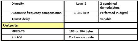
20 DVB-T/H Diversity Decoder Specifications: Page 20 of 22

21 Antenna Selector Switch Figure 26: Diversity Antenna Calibrated RF Switch Diversity Antenna Calibrated RF Switch Antenna Factor Below is an example of the Diversity Antenna Calibrated RF Switch characterization table located in the Antenna section of the System User Manual. Page 21 of 22

22 Figure 27: Example RF Switch Characterization To calculate the number to be entered into the Antenna Factor field in the Job Editor add the absolute value of the following numbers: 1. The Antenna Factor from the Antenna at the frequency of use 2. The loss of the cable connecting the antenna to the RF switch at the frequency of use 3. The loss of the RF switch at the frequency of use. For instance if we are measuring a signal at 600 MHz we might use the following numbers db from the Antenna Factor table in the Antenna Section of the System Manual 2. 2 db from the Cable Loss table in the Antenna Section of the System Manual db from the RF Switch Characterization table in the Antenna Section of the System Manual For this example the Antenna Factor entered in the Job Editor Antenna Factor Field is 32.2 db. 25 db + 2 db db = 32.2 db Page 22 of 22
Z Technology DSS5600A USER MANUAL Version 2.17
 Z Technology DSS5600A USER MANUAL Version 2.17 Z Technology, Inc. 14950 NW Greenbrier Parkway Beaverton, OR 97006 USA Tel: 503-614-9800 Fax: 503-614-9898 DSS5600A User Manual WARRANTY Z Technology Inc.
DTVM 2000(T) Digital Terrestrial Television Transmitter Monitor
 Digital Terrestrial Television Transmitter Monitor") DTVM 2000(T) Digital Terrestrial Television Transmitter Monitor The DTVM 2000(T) Digital Terrestrial Television Transmitter Monitor range has been designed for DVB signal quality measurement applications.
DTVM 2000(T) Digital Terrestrial Television Transmitter Monitor The DTVM 2000(T) Digital Terrestrial Television Transmitter Monitor range has been designed for DVB signal quality measurement applications.
DIGIAIR PRO USER MANUAL
 DIGIAIR PRO USER MANUAL Content: DIGIAIR PRO Description 2 1 GETTING STARTED 3 1.1 POWER ON/OFF 3 1.2 POWER SUPPLY AND BATTERY 3 1.3 HOW TO USE THE METER 3 1.4 ATTENUATOR 4 2 DESCRIPTION OF THE FUNCTIONS
TV SIGNAL LEVEL METER USER MANUAL
 TV SIGNAL LEVEL METER USER MANUAL - 0 - 1. Overview (1) (1) RF input (2) (3) A D E B C (2) Speaker (3) LCD display (4) Charger indicator (5) RS232 communication port (6) DC-IN port F G A. The battery icon
Signal Generators for Anritsu RF and Microwave Handheld Instruments
 Measurement Guide Signal Generators for Anritsu RF and Microwave Handheld Instruments BTS Master Spectrum Master Tracking Generator Option 20 Vector signal Generator Option 23 Anritsu Company 490 Jarvis
Sensitivity of Series Direction Finders
 Sensitivity of Series 6000-6100 Direction Finders 1.0 Introduction A Technical Application Note from Doppler Systems April 8, 2003 This application note discusses the sensitivity of the 6000/6100 series
120W UHF Transmitter/Repeater
 Product Features 470 MHz - 860 MHz Broadband Transmitter/Repeater LDMOS Power Amplifier provides 120 Watt output for ATSC, ATSC-M/H, CMMB, DTMB, DVB-T/H, DVB-T2, DVB-SH, ISDB-T/TB,, DAB, DAB+ and T-DMB
UNIVERSITATEA POLITEHNICA BUCUREŞTI FACULTATEA DE ELECTRONICĂ, TELECOMUNICAŢII ŞI TEHNOLOGIA INFORMAȚIEI LABORATOR TELEVIZIUNE
 UNIVERSITATEA POLITEHNICA BUCUREŞTI FACULTATEA DE ELECTRONICĂ, TELECOMUNICAŢII ŞI TEHNOLOGIA INFORMAȚIEI LABORATOR TELEVIZIUNE VIDEO QUALITY MEASUREMENT IN DIGITAL TELEVISION SYSTEMS 1. DVB The Digital
Adoption of this document as basis for broadband wireless access PHY
 Project Title Date Submitted IEEE 802.16 Broadband Wireless Access Working Group Proposal on modulation methods for PHY of FWA 1999-10-29 Source Jay Bao and Partha De Mitsubishi Electric ITA 571 Central
1.1 The equipments and programs used in the measurements are. 1.3 Measuring the signal power and adjacent channel power with the spectrum analyzer
 Appendix-A: Measurement equipments 1.1 The equipments and programs used in the measurements are - Nokia Mediamaster 9730C set-top box (Image in Appendix-C) - Rohde&Schwarz SMBV100A signal generator (Image
Multi-Way Diversity Reception for Digital Microwave Systems
 Multi-Way Diversity Reception for Digital Microwave Systems White paper Table of Contents 1. GENERAL INFORMATION 3 1.1 About this document 3 1.2 Acknowledgements 3 2. THE NEED FOR DIVERSITY RECEPTION 3
Systems for Audio and Video Broadcasting (part 2 of 2)
") Systems for Audio and Video Broadcasting (part 2 of 2) Ing. Karel Ulovec, Ph.D. CTU in Prague, Faculty of Electrical Engineering xulovec@fel.cvut.cz Only for study purposes for students of the! 1/30 Systems
Systems for Audio and Video Broadcasting (part 2 of 2) Ing. Karel Ulovec, Ph.D. CTU in Prague, Faculty of Electrical Engineering xulovec@fel.cvut.cz Only for study purposes for students of the! 1/30 Systems
RECOMMENDATION ITU-R BT Error-correction, data framing, modulation and emission methods for digital terrestrial television broadcasting
 Rec. ITU-R BT.1306-3 1 RECOMMENDATION ITU-R BT.1306-3 Error-correction, data framing, modulation and emission methods for digital terrestrial television broadcasting (Question ITU-R 31/6) (1997-2000-2005-2006)
PerMIT. A complete broadcast measurement and analysis solution
 Enkom Inventis is presenting a high-performance solution to analyse your broadcast networks. The new Performance Measurement & Investigation Tool for Digital Broadcasting (PerMIT) is a powerful tool and
Digiair Pro ATSC USER MANUAL
 Digiair Pro ATSC USER MANUAL Content: DIGIAIR PRO Description 2 1 GETTING STARTED 3 1.1 POWER ON/OFF 3 1.2 POWER SUPPLY AND BATTERY 3 1.3 HOW TO USE THE METER 3 ATTENUATOR 4 DIGITAL MODE 4 2 DESCRIPTION
Welcome to the. «DVB-H for TV on Mobiles» Gerard FARIA de SOUZA NEVES Teamcast
 Welcome to the «DVB-H for TV on Mobiles» Gerard FARIA de SOUZA NEVES (gerard.faria@teamcast.com) DVB-H Workshop -SET'05 - Sao Paulo - 22 September 2005 1 Technologies fight to serve TV on Mobile But numerous
Getting Started Guide
 MaxEye Digital Audio and Video Signal Generation ISDB-T Signal Generation Toolkit Version 2.0.0 Getting Started Guide Contents 1 Introduction... 3 2 Installed File Location... 3 2.1 Soft Front Panel...
APX Mobile and Portable Automated Test and Alignment
 APX Mobile and Portable Automated Test and Alignment Software Updates First things first! Be sure to check that you are running the latest software versions for the 8800SX and its applications. Visit the
Power Meter. Measurement Guide. for Anritsu RF and Microwave Handheld Instruments BTS Master Site Master Spectrum Master Cell Master
 Measurement Guide Power Meter for Anritsu RF and Microwave Handheld Instruments BTS Master Site Master Spectrum Master Cell Master Power Meter Option 29 High Accuracy Power Meter Option 19 Inline Peak
TV Test Receiver EFA, Models 40/43 (DVB-T)
") TV Test Receiver EFA, Models 40/43 (DVB-T) Comprehensive analysis/demodulation/monitoring of digital terrestrial TV signals All DVB-T modes supported according to ETS300744 High-end demodulator High-end
TV Test Receiver EFA, Models 40/43 (DVB-T) Comprehensive analysis/demodulation/monitoring of digital terrestrial TV signals All DVB-T modes supported according to ETS300744 High-end demodulator High-end
8800SX DMR Repeater Test Option 06
 8800SX DMR Repeater Test Option 06 DMR Repeater Test Option The DMR Repeater test option allows testing of a DMR Repeater that is in conventional DMR Mode. Trunking or analog configurations are not supported.
APPH6040B / APPH20G-B Specification V2.0
 APPH6040B / APPH20G-B Specification V2.0 (July 2014, Serial XXX-XX33XXXXX-XXXX or higher) A fully integrated high-performance cross-correlation signal source analyzer for to 7 or 26 GHz 1 Introduction
Hierarchical Modulation & SFN
 Hierarchical Modulation & SFN 數位電視系統原理及軟體技術 銘傳大學 : 陳游利 元智大學 : 黃依賢 1 DVB-T Transmitter Diagram MPEG-2 System Channel Coding Modulation 2 Agenda DVB-T Transmission System DVB-T Coded OFDM Tutorial DVB-T
BRB900 GPS Telemetry System August 2013 Version 0.06
 BRB900 GPS Telemetry System August 2013 Version 0.06 As of January 2013, a new model of the BRB900 has been introduced. The key differences are listed below. 1. U-blox GPS Chipset: The Trimble Lassen IQ
Ansoft Designer Tutorial ECE 584 October, 2004
 Ansoft Designer Tutorial ECE 584 October, 2004 This tutorial will serve as an introduction to the Ansoft Designer Microwave CAD package by stepping through a simple design problem. Please note that there
Product Description 2-1
 2 Product Description 2.1 Chapter Overview This chapter provides an overall description of the STRATA TX System, its components, and its capabilities. Here are the topics covered: Topic System Description
Complimentary Reference Material
 Complimentary Reference Material This PDF has been made available as a complimentary service for you to assist in evaluating this model for your testing requirements. TMG offers a wide range of test equipment
Gentec-EO USA. T-RAD-USB Users Manual. T-Rad-USB Operating Instructions /15/2010 Page 1 of 24
 Gentec-EO USA T-RAD-USB Users Manual Gentec-EO USA 5825 Jean Road Center Lake Oswego, Oregon, 97035 503-697-1870 voice 503-697-0633 fax 121-201795 11/15/2010 Page 1 of 24 System Overview Welcome to the
Basic Transceiver tests with the 8800S
 The most important thing we build is trust ADVANCED ELECTRONIC SOLUTIONS AVIATION SERVICES COMMUNICATIONS AND CONNECTIVITY MISSION SYSTEMS Basic Transceiver tests with the 8800S Basic Interconnects Interconnect
Frequency Agility and Barrage Noise Jamming
 Exercise 1-3 Frequency Agility and Barrage Noise Jamming EXERCISE OBJECTIVE To demonstrate frequency agility, a radar electronic protection is used against spot noise jamming. To justify the use of barrage
TECHNICAL NOTES. MT-4 Radio Systems. TN247 VR-4E VHF MT-4E Receiver. Specifications. Models Available. Receiver Operating Frequency
 MADE IN CANADA TN247 VR-4E VHF MT-4E Receiver USB CNTL BUS A D RECEIVER FREQUENCY (MHz) SQ. DISABLE NORM OFF REF IN RF IN The VR-4E VHF receiver is an FM radio module capable of analog operation in 12.5
Nikon D7100 Camera Kit. -Checklist and Operations Manual-
 Airborne Digital Reconnaissance System (ADRS) Nikon D7100 Camera Kit -Checklist and Operations Manual- V4.2 October 21, 2014 National Headquarters, Civil Air Patrol 2 1.0 Equipment Pre-Mission Check 1.1
TT7000R4. DS Instruments. D text. RF Power Meter, Signal Generator, Frequency Counter. -Key Features-
 -Key Features- DS Instruments Power Meter 50 to 7000MHz Frequency Counter 100 to 7000MHz R4 RF Power Meter, Signal Generator, Frequency Counter Signal Generator 300 to 9600MHz Internal 31dB Step Attenuator
Model 7000 Series Phase Noise Test System
 Established 1981 Advanced Test Equipment Rentals www.atecorp.com 800-404-ATEC (2832) Model 7000 Series Phase Noise Test System Fully Integrated System Cross-Correlation Signal Analysis to 26.5 GHz Additive
ExpoM - ELF User Manual
 ExpoM - ELF User Manual Version 1.4 ExpoM - ELF User Manual Contents 1 Description... 4 2 Case and Interfaces... 4 2.1 Overview... 4 2.2 Multi-color LED... 5 3 Using ExpoM - ELF... 6 3.1 Starting a Measurement...
PROWATCHNeo. PROWATCHNeo monitoring system WEB SERVER CONTROL HEVC H K SNMP COMPATIBLE. High Effciency Video Codec
 monitoring system PROWATCHNeo SNMP COMPATIBLE Easily scalable WEB SERVER CONTROL Total flexibility HEVC H.265 High Effciency Video Codec 4 K High Definition PROWATCHNeo monitoring system Remote monitoring
Dragon. manual version 1.7
 Dragon manual version 1.7 Contents DRAGON TOP PANEL... 2 DRAGON STARTUP... 2 DRAGON STARTUP SCREEN... 2 DRAGON INFO SCREEN... 3 DRAGON MAIN SCREEN... 3 TURNING ON A TRANSMITTER... 4 CHANGING MAIN SCREEN
DVB-T/H Portable Test Transmitter
 Product Features Portable Design Durable Enclosure L-Band RF Output Full hierarchical mode support SFN and MFN support Near seamless switching between inputs Superior MER performance Outstanding Linear
AA-35 ZOOM. RigExpert. User s manual. Antenna and cable analyzer
 AA-35 ZOOM Antenna and cable analyzer RigExpert User s manual . Table of contents Introduction Operating the AA-35 ZOOM First time use Main menu Multifunctional keys Connecting to your antenna SWR chart
PT 5879 MIP INSERTER AGS*/MIP. ransmitter. TRX ID TAG data. TRX ID TAG data. TRX ID TAG data. TRX ID TAG data. data Reset Count Timing
 PT 5879 MIP INSERTER *supports pro any existing Carousel management ransmitter 1 PPS 10 MHz AGS*/MIP G-2 TS. MIP 0 0 0 0 0 0 0 0 control DVB-T Modulation (SFN) DVB Chan I NTRODUCTION The Single Frequency
carriers are carrying synchronization and control signals to the receivers, but most of carriers conveys signal-data to the receiver.
 Hierarchical encoding an interesting specialty within DVB-T and DVB-H. INTRODUCTION Highly promoted by the German expert group in the DVB-T group, hierarchical encoding represents a mode, which is compromise
Antenna Measurements using Modulated Signals
 Antenna Measurements using Modulated Signals Roger Dygert MI Technologies, 1125 Satellite Boulevard, Suite 100 Suwanee, GA 30024-4629 Abstract Antenna test engineers are faced with testing increasingly
Quick Start Guide for the PULSE PROFILING APPLICATION
 Quick Start Guide for the PULSE PROFILING APPLICATION MODEL LB480A Revision: Preliminary 02/05/09 1 1. Introduction This document provides information to install and quickly start using your PowerSensor+.
TEST REPORT MOBILE MICROWAVE VIDEO TRANMITTER FCC ID: FC3HDX2025D MODEL: HDX-1100S. APPLICANT: VISLINK, Inc. May 7, 2013 PAGE 1 OF 33
 TEST REPORT MOBILE MICROWAVE VIDEO TRANMITTER FCC ID: FC3HDX2025D MODEL: HDX-1100S APPLICANT: VISLINK, Inc. May 7, 2013 PAGE 1 OF 33 TABLE OF CONTENTS Section 1 INTRODUCTION 3 APPLICATION 4 TECHNICAL DATA
BandMaster V Manual. Installation
 BandMaster V Manual Installation Installing and configuring the BM-5 BandMaster V is a simple process. All the configuration process is done from the front panel. Installation and configuration steps are
PGT313 Digital Communication Technology. Lab 3. Quadrature Phase Shift Keying (QPSK) and 8-Phase Shift Keying (8-PSK)
 and 8-Phase Shift Keying (8-PSK)") PGT313 Digital Communication Technology Lab 3 Quadrature Phase Shift Keying (QPSK) and 8-Phase Shift Keying (8-PSK) Objectives i) To study the digitally modulated quadrature phase shift keying (QPSK) and
PGT313 Digital Communication Technology Lab 3 Quadrature Phase Shift Keying (QPSK) and 8-Phase Shift Keying (8-PSK) Objectives i) To study the digitally modulated quadrature phase shift keying (QPSK) and
QAM Snare Snoop User Manual
 QAM Snare Snoop User Manual QS-Snoop-v2.0 2/21/2018 This document details the functions and operation of the QAM Snare Snoop leakage detector Table of Contents Overview... 5 Screen Navigation... 6 Settings...
EXHIBIT 7: MEASUREMENT PROCEDURES Pursuant 47 CFR 2.947
 EXHIBIT 7: MEASUREMENT PROCEDURES Pursuant 47 CFR 2.947 7.1 RF Power -- Pursuant to 47 CFR 2.947(c) Method of Conducted Output Power Measurement: Adaptation of TIA/EIA-603-A clause 2.2.1 for Pulsed Measurements
R&S ETH Handheld TV Analyzer Specifications
 R&S ETH Handheld TV Analyzer Specifications year Data Sheet Version 11.00 CONTENTS Definitions... 3 Specifications... 4 TV analyzer... 4 Frequency... 4 Level... 4 RF preselection (R&S ETH-K1 option)...
Deceptive Jamming Using Amplitude-Modulated Signals
 Exercise 3-1 Deceptive Jamming Using Amplitude-Modulated Signals EXERCISE OBJECTIVE To demonstrate the effect of AM noise and repeater inverse gain jamming, two angular deceptive EA used against sequential
Suitable firmware can be found on Anritsu's web site under the instrument library listings.
 General Caution Please use a USB Memory Stick for firmware updates. Suitable firmware can be found on Anritsu's web site under the instrument library listings. If your existing firmware is older than v1.19,
JD746A/JD786A CellAdvisor RF Analyzer
 JD746A/JD786A CellAdvisor RF Analyzer JD746A JD786A Spectrum Analyzer: 100 khz to 4 GHz 9 khz to 8 GHz Cable and Antenna Analyzer: 5 MHz to 4 GHz 5 MHz to 6 GHz RF Power Meter: 10 MHz to 4 GHz 10 MHz to
Rockwell Collins, Inc. VHF Users Manual
 Rockwell Collins, Inc. VHF-2200 Users Manual This manual provided to the FCC for product guidance, it should not be used by our OEM customers. Scope: This document will detail information required to install
AirScope Spectrum Analyzer User s Manual
 AirScope Spectrum Analyzer Manual Revision 1.0 October 2017 ESTeem Industrial Wireless Solutions Author: Date: Name: Eric P. Marske Title: Product Manager Approved by: Date: Name: Michael Eller Title:
Localizer provides signal generation over the Localizer band of to MHz with 90 Hz and 150 Hz tones, amplitude modulated
 The IFR 4000 verifies the operation and installation of ILS, VOR and Marker Beacon receivers and VHF/UHF AM/FM and HF AM/SSB transceivers. The IFR 4000, with its lightweight size (under 8 lbs.), long run
TC-2300B DAB/DMB Tester
 TC-2300B DAB/DMB Tester Product Information TC-2300B DAB/DMB Tester supports the Eureka-147 (ESTI EN 301 500) system, freely changes every parameter related to protocols in a GUI operating system and simultaneously
Dear Valued Customer,
 Dear Valued Customer, Thank you for choosing Listen! All of us at Listen are dedicated to provide you with the highest quality products available. We take great pride in their outstanding performance because
MATLAB SIMULATION OF DVB-H TRANSMISSION UNDER DIFFERENT TRANSMISSION CONDITIONS
 MATLAB SIMULATION OF DVB-H TRANSMISSION UNDER DIFFERENT TRANSMISSION CONDITIONS Ladislav Polák, Tomáš Kratochvíl Department of Radio Electronics, Brno University of Technology Purkyňova 118, 612 00 BRNO
IC-400pro - RADIOAFICION.COM
 PROCEDURES IC-400pro - 5- PREPARATION When you adjust the contents on pages 5-5 and 5-6, SOFT- WARE, the optional CS-400PRO ADJ SOFTWARE (Rev..0 or later), *OPC- JIG CABLE (modified OPC- CLONING CABLE;
User s Manual For PAMS. Portable Attenuation Measurement System /
 User s Manual For PAMS Portable Attenuation Measurement System www.praxsym.com 217/897-1744 2 Contents I. Introduction..... 3 1.0 General Information... 4 1.1 Equipment Purpose...4 1.2 Equipment List...4
Agilent PSA Series Spectrum Analyzers Noise Figure Measurements Personality
 Agilent PSA Series Spectrum Analyzers Noise Figure Measurements Personality Technical Overview with Self-Guided Demonstration Option 219 The noise figure measurement personality, available on the Agilent
USB Multifunction Arbitrary Waveform Generator AWG2300. User Guide
 USB Multifunction Arbitrary Waveform Generator AWG2300 User Guide Contents Safety information... 3 About this guide... 4 AWG2300 specifications... 5 Chapter 1. Product introduction 1 1. Package contents......
SECTION WIRELESS CLOCK/TONE GENERATOR SYSTEM
 SECTION 13805 WIRELESS CLOCK/TONE GENERATOR SYSTEM PART 1 GENERAL 1.01 SUMMARY A. Section Includes: Satellite based, synchronized wireless clock/tone generator system, including clocks, tone generator,
DMR Application Note Testing MOTOTRBO Radios On the R8000 Communications System Analyzer
 DMR Application Note Testing MOTOTRBO Radios On the R8000 Communications System Analyzer April 2 nd, 2015 MOTOTRBO Professional Digital Two-Way Radio System Motorola and MOTOTRBO is registered in the U.S.
TELE-OPERATOR UTS v.16 DVB-T / T2 RF + DVB + TS monitor
 TELE-OPERATOR UTS v.16 DVB-T / T2 RF + DVB + TS monitor 2017.02.10 UTS v.16 DVB-T/T2 Antenna mode Signal strength between -20 - -90 dbm High sensitivity RF input ASI output Serial port control Currently
R&D White Paper WHP 058. Diversity reception of Digital Terrestrial Television (DVB-T) Research & Development BRITISH BROADCASTING CORPORATION
 Research & Development BRITISH BROADCASTING CORPORATION") R&D White Paper WHP 58 April 23 Diversity reception of Digital Terrestrial Television (DVB-T) J. Mitchell and J.A. Green Research & Development BRITISH BROADCASTING CORPORATION BBC Research & Development
R&D White Paper WHP 58 April 23 Diversity reception of Digital Terrestrial Television (DVB-T) J. Mitchell and J.A. Green Research & Development BRITISH BROADCASTING CORPORATION BBC Research & Development
1 UAT Test Procedure and Report
 1 UAT Test Procedure and Report These tests are performed to ensure that the UAT Transmitter will comply with the equipment performance tests during and subsequent to all normal standard operating conditions
The DR-2000 is a high-performance receiver designed to enable highly sophisticated data and signal processing over a wide frequency spectrum.
 The DR-2000 is a high-performance receiver designed to enable highly sophisticated data and signal processing over a wide frequency spectrum. L3 (L3 T&RF) DR-2000 receiving unit incorporates a high-performance
Series MICROWAVE LINKS DIGITAL & ANALOG - FIXED & MOBILE. The high quality, professional and cost-effective solution
 MICROWAVE LINKS DIGITAL & ANALOG - FIXED & MOBILE Series PM The high quality, professional and cost-effective solution In 1982 ABE Elettronica introduced The Microwave Link line which was immediately successful,
Maxiva TM VAX Compact
 Maxiva TM VAX Compact Low Power VHF Band III TV/DAB Transmitter / Transposer / Gap Filler The Maxiva VAX Compact family of VHF Band III solid-state transmitters, transposers/translators and gap fillers
Application Note: DMR Application Note Testing MOTOTRBO Radios On the Freedom Communications System Analyzer
 : DMR Application Note Testing MOTOTRBO Radios On the Freedom Communications System Analyzer MOTOTRBO Professional Digital Two-Way Radio System Motorola and MOTOTRBO is registered in the U.S. Patent and
User s Manual. Configurable Messenger Transmitter High-Power Rack-Mount Kit (CMT-R) The most important thing we build is trust.
 The most important thing we build is trust.") User s Manual The most important thing we build is trust. Configurable Messenger Transmitter High-Power Rack-Mount Kit (CMT-R) Cobham Surveillance GMS Products 1916 Palomar Oaks Way Ste 100 Carlsbad, CA
User s Manual The most important thing we build is trust. Configurable Messenger Transmitter High-Power Rack-Mount Kit (CMT-R) Cobham Surveillance GMS Products 1916 Palomar Oaks Way Ste 100 Carlsbad, CA
Mastr III P25 Base Station Transmitter Tune-up Procedure
 Mastr III P25 Base Station Transmitter Tune-up Procedure 1. Overview The Mastr III Base Station transmitter alignment is performed in several steps. First, the Transmit Synthesizer module is aligned to
ST600 TRANSMITTER OPERATING INSTRUCTIONS
 ST600 TRANSMITTER OPERATING INSTRUCTIONS 1892 1273 These operating instructions are intended to provide the user with sufficient information to install and operate the unit correctly. The Wood and Douglas
Technical Equipment Specification
 STATE OF CALIFORNIA Office of the State Chief Information Officer Public Safety Communications Division Technical Equipment Specification Equipment Type: Transmitter/Receiver Mobile Relay/Base/Control
TC-2300B DAB/DMB Tester
 www.tescom.co.kr DAB/DMB Tester Realtime Ensemble Mux (Unlimited Pattern Generation) OFDM Modulator RF Up-Converter Support Eureka-147(ETSI EN 301 400) protocol Combination test equipment (OFDM modulator
Testing The Effective Performance Of Ofdm On Digital Video Broadcasting
 The 1 st Regional Conference of Eng. Sci. NUCEJ Spatial ISSUE vol.11,no.2, 2008 pp 295-302 Testing The Effective Performance Of Ofdm On Digital Video Broadcasting Ali Mohammed Hassan Al-Bermani College
8. TERRESTRIAL DIGITAL VIDEO BROADCASTING MEASUREMENT
 Goals of measurement 1) Display spectrum of output signal from transmitter of digital video broadcasting. 2) Draw constellation diagrams of particular sub-carriers of output signal. 3) Determine minimum
The Measurement of Digitally Modulated RF Signals (The Basic Principles) Chris Swires, FSCTE. Swires Research.
 Chris Swires, FSCTE. Swires Research.") The Measurement of Digitally Modulated RF Signals (The Basic Principles) Chris Swires, FSCTE. Swires Research. This paper was first presented to the Society of Cable Telecommunications Engineers at the
The Measurement of Digitally Modulated RF Signals (The Basic Principles) Chris Swires, FSCTE. Swires Research. This paper was first presented to the Society of Cable Telecommunications Engineers at the
BANTAM INSTRUMENTS SOFTWARE USER S MANUAL MIL-STD-461E PRE-COMPLIANCE MEASUREMENT SYSTEM MODEL EMC-461. Model EMC-461 Software User s Manual
 BANTAM INSTRUMENTS MIL-STD-461E PRE-COMPLIANCE MEASUREMENT SYSTEM MODEL EMC-461 SOFTWARE USER S MANUAL MIL-STD-461E PRE-COMPLIANCE MEASUREMENT SYSTEM MODEL EMC-461 Software User s Manual BANTAM INSTRUMENTS
ZebraII Manual Table of Contents
 ZebraII Manual Table of Contents Section Page ZebraII Introduction... 2 ZebraII Block Diagram...2 Before you power up... 3 Power up... 3 Table 1 IS-97 Base Station...3 Specification... 4 Zebra Setup to
Your Network. Optimized.
 Over 20 years of research both at the National Institute of Standards and Technology (NIST) and in private industry have been dedicated to the research and development of Symmetricom s phase noise and
TC-2300B DAB/DMB Tester
 TC-2300B DAB/DMB Tester Product Information TC-2300B DAB/DMB Tester supports the Eureka-147 (ESTI EN 301 500) system, freely changes every parameter related to protocols in a GUI operating system and simultaneously
Introduction to Lab Instruments
 ECE316, Experiment 00, 2017 Communications Lab, University of Toronto Introduction to Lab Instruments Bruno Korst - bkf@comm.utoronto.ca Abstract This experiment will review the use of three lab instruments
TECHNICAL SPECIFICATION FOR RF (TEST &MEASUREMENT) DEVICE
 DEVICE") TECHNICAL SPECIFICATION FOR RF (TEST &MEASUREMENT) DEVICE Test and measuring device supports the following measurement functions: A- Cable and Antenna Analyzer, 2 MHz to 4 GHz. B- Spectrum Analyzer, 100
TECHNICAL SPECIFICATION FOR RF (TEST &MEASUREMENT) DEVICE Test and measuring device supports the following measurement functions: A- Cable and Antenna Analyzer, 2 MHz to 4 GHz. B- Spectrum Analyzer, 100
The RCB-2000 is a compact receiving system that combines two high-performance telemetry RF sections.
 The RCB-2000 is a compact receiving system that combines two high-performance telemetry RF sections. L3 Telemetry& RF products (L3 T&RF) RCB-2000 is a compact, receiving system that combines two high-performance
Software-only implementation of DVB-H
 Software-only implementation of DVB-H Daniel Iancu* a, Hua Ye a, John Glossner a, Andrei Iancu a, Jarmo Takala b a Sandbridge Technologies Inc., 120 White Plains Rd, Tarrytown, NY 10591; b Tampere University
Maxiva UAXT Ultra-Compact/ VAXT Ultra-Compact Low Power UHF/VHF Transmitter / Transposer / Gap Filler
 Maxiva UAXT Ultra-Compact/ VAXT Ultra-Compact Low Power UHF/VHF Transmitter / Transposer / Gap Filler The new Maxiva UAXT & VAXT Ultra Compact family of UHF & VHF solid-state Transmitters, Transposers
PC Tune PC Tune Test Procedures for 5100 Series Portable Radios
 PC Tune PC Tune Test Procedures for 5100 Series Portable Radios Part Number 002-9998-6513014 August 2008 Copyright 2006, 2007, 2008 by EFJohnson Technologies The EFJohnson Technologies logo, PC Configure,
MEX II. Multimode TV Exciter HE ANALOG / DIGITAL
 ANALOG / DIGITAL Multimode TV Exciter Fully numerical signal elaboration and modulation Adaptive pre-distorter and pre-equalizer Multi-Standard equipment Dual Cast transmitter Band I Band III Band IV/V
DSTS-5A/2C User's Manual
 ELECTRONIC DEVICES INC. P.O. BOX 15037, CHESAPEAKE, VA 23328. PH 757-421-2968 FAX 421-0518 DSTS-5A/2C User's Manual 1. PACKING LIST 2. OVERVIEW 3. CONNECTING THE DSTS-5A/2C TO A COMPUTER 4. CONNECTING
Microphone audio, from the MFJ-1278B to your transmitter. Ground, audio and PTT common. Push-to-talk, to allow the MFJ-1278B to key your transmitter.
 Computer interfacing, covered in the previous chapter, is only half the interfacing task. The other half is connecting your MFJ-1278B to your radios. MFJ-1278B Radio Ports Interfacing the MFJ-1278B to
DragonLink Advanced Transmitter
 DragonLink Advanced Transmitter A quick introduction - to a new a world of possibilities October 29, 2015 Written by Dennis Frie Contents 1 Disclaimer and notes for early release 3 2 Introduction 4 3 The
PathTrax. User s Manual. PathTrax. The solution for making easy shielding effectiveness measurements
 PathTrax User s Manual The solution for making easy shielding effectiveness measurements PathTrax TABLE OF CONTENTS Chapter 1 General Information 2 Introduction Specifications Receiver Transmitter Chapter
DVB-H and DVB-SH-A Performance in Mobile and Portable TV
 VOL. 2, NO. 4, DECEMBER 211 DVB-H and DVB-SH-A Performance in Mobile and Portable TV Ladislav Polák, Tomáš Kratochvíl Department of Radio Electronics, Brno University of Technology, Purkyňova 118, 612
8853Q Spectrum Analyzer
 Increases Productivity by Providing a Complete Set of Spectrum Analysis Tests in One Instrument Intuitive User Interface Shortens Learning Curve Full-Featured, High-Performance, Remote Operation Automated
GPS10RBN-26: 10 MHz, GPS Disciplined, Ultra Low Noise Rubidium Frequency Standard
 GPS10RBN-26: 10 MHz, GPS Disciplined, Ultra Low Noise Rubidium Standard Key Features Completely self-contained unit. No extra P.C needed. Full information available via LCD. Rubidium Oscillator locked
Spectrum Analyzer. Spectrum Analyzer. Antenna Panel Inputs. Auxiliary Antenna Inputs. Two models available: 24 GHz and 8 GHz OSCOR
 Whip antenna extension connector Auto Switching (utilizes 5 independent antennas) OSCOR ADVANTAGES FULL 24 GHz COVERAGE Headphone Jack SWEEPS FROM 10 khz TO 24 GHz AT 12.2 khz STEPS IN LESS THAN 1 SECOND
Installed Radio Testing with the 3500
 Application Note Installed Radio Testing with the 3500 Aeroflex has uniquely designed the Aeroflex 3500 portable radio test set for complete testing of installed radio communication systems. The 3500 is
FCC ID: A3LSLS-BD106Q. Report No.: HCT-RF-1801-FC003. Plot Data for Output Port 2_QPSK 9 khz ~ 150 khz Middle channel 150 khz ~ 30 MHz Low channel
 Plot Data for Output Port 2_QPSK 9 khz ~ 150 khz Middle channel 150 khz ~ 30 MHz Low channel 30 MHz ~ 1 GHz Middle channel 1 GHz ~ 2.491 GHz Low channel 2.695 GHz ~ 12.75 GHz High channel 12.75 GHz ~ 26.5