Basic Transceiver tests with the 8800S
|
|
|
- Barbara Marshall
- 5 years ago
- Views:
Transcription


1 The most important thing we build is trust ADVANCED ELECTRONIC SOLUTIONS AVIATION SERVICES COMMUNICATIONS AND CONNECTIVITY MISSION SYSTEMS Basic Transceiver tests with the 8800S
2 Basic Interconnects Interconnect 1 Basic Transmitter / Receiver tests For basic Transmitter and Receiver tests, connect the 8800S TR port to the Radio ANT port. RF Test cable The TR port on the 8800S is a bi-directional RF port that can generate a signal to test a receiver as well as measure transmitter characteristics like Power, Frequency and Modulation. This port is rated at 50 Watts input. Measurements to 125 Watts are possible observing Duty cycle to prevent over heating. 1

3 Access to built in Presets The small tab at the top center of the display allows access to the launch bar. Simply touch the tab and the launch bar will expand. Presets quickly configure standard tile selections and locations. Press the Utilities tab and then the Presets menu to rapidly configure the 8800S for either Analog or Digital testing. 2
4 Access to built in setup files Setup files store complete instrument configurations that include all settings. To open the menu, simply touch the tab and the menu will expand. Every 8800S is preconfigured with a large group of sample setups to configure the instrument for a variety of basic tests. Press the Utilities tab and then the Store / Recall item to gain access to the pre-configured test setups that are within every instrument. 3
5 Store / Recall Navigation When first entering the Store/Recall menu, a folder named Sample Setups will be visible. To enter the folder, touch or highlight the Sample Setups item on the list then press the icon to enter the folder. 4
6 The Sample Setups After entering the Sample Setups folder, there are a variety of basic test folders available. This presentation will show some of the ones available for FM and AM transceiver testing. Highlight the Analog FM folder and press the icon to enter the folder. 5

7 Configure the 8800S for FM Transmitter test Highlight the TX_Test_FM setup file and press the Recall button. This will configure the 8800S to perform basic FM transmitter tests. 6

8 Measure TX Frequency and Power Always Zero the Power meter before taking power measurements. 1. Zero the Power meter. 2. Connect the transmitter as illustrated on slide Enter the transmitter frequency on the Receiver Tile. 4. Key the transmitter. 5. Measure and record the RF Error. This is the transmitter frequency error. 6. Measure and record the RF Power Avg reading. This is the Transmit Power level. 7


9 Improving the power measurement If the loss of the test cable is known, the power meter can be compensated by that amount by entering the cable offset value as a negative number on the Expanded Receiver tile. After entering this offset, the transmitter output now reads 3.26 watts. This radio had been configured to transmit at 3.2 Watts in this frequency band. 8

10 Measure Modulation (Basic Check) Home Button A basic transmitter modulation check can be done after making the following changes to the current setup. 1. Press the Home button on the 8800S front panel. 2. Press the Speaker control to enable the speaker. 3. Press the Home button again to minimize the menu. 4. Note that Audio Volume and Squelch controls are also available on this menu. These may need to be adjusted later as necessary. 9


11 Measure Modulation (Basic Check) On the AF Gen tile, press the Fast Stack icon until the Audio Config tile is revealed. Press the icon on the Audio Config tile to reveal the audio signal routing table. Establish the following routings: 10

12 Measure Modulation (Basic Check) To measure sub-audible tones, set the AFBW value to 300 Hz LP to filter out audio signals above 300 Hz. Key the transmitter under test and speak into the radio microphone. Audio should be heard in the 8800S speaker. Voice modulation should be visible on the Oscilloscope. Modulation value should be visible on the Modulation meter. For AM Modulation testing, change the Demod value on the Receiver tile from FM to AM. 11

13 Measure Modulation (Advanced Check) To externally modulate the transmitter with a tone, connect the 8800S Audio Out port to the radio s Microphone input. The AF Gen tile can then be used to apply a tone to modulate the transmitter. Additional testing of Transmitter distortion and microphone sensitivity can now be performed. 12


14 Measure Modulation (Advanced Check) 13 With the radio keyed and connected as shown in the previous slide, additional measurements can be made. Enable the AF Gen and adjust the AF Gen Level to achieve the desired modulation results. Measure the transmitter distortion. Turn the AF Generator OFF when testing is complete. Note: The RF Generator must not be Enabled when doing this test.

15 Additional signaling formats Expanding the AF Generator tile reveals a number of other signaling formats that can be used instead of a steady state tone. The tabs on the side can be used to access: Two Tone Tone Remote Tone Sequential Each selection will reconfigure the tile for the selected operation. 14


16 Basic Receiver Test To test the radio receiver, recall the RX_Test_FM setup file from the Store / Recall screen from the Utilities Store / Recall menu. Select the sample setup RX_Test_FM setup file and press the Recall button. 15
.")
17 Basic Receiver Test On the Generator Tile, enter the radio s receive frequency in the Frequency entry field. Enable the RF Generator (On). 16

18 Basic Receiver Test On the Freq Select tile, press the Fast Stack icon until the Audio Config tile is revealed. Press the icon on the Audio Config tile to reveal the audio signal routing table. Establish the following routings: 17

19 Basic Receiver Test On the Audio Config tile, select the Fast Stack icon to reveal the Modulation tile. The default setting for this setup is modulation at a 1 khz rate at 2.5 khz deviation. Both values may be modified as necessary. Pressing the Expand icon reveals a second modulator that may be used in addition to the first. The two tones will be summed and applied to the generator modulator. Audio should now be heard from the receiver under test. The radio s volume and squelch settings may need to be adjusted. 18
20 Basic Receiver Test For AM Receiver testing, change the Modulation mode from FM to AM on the Modulation tile. 19

21 Advanced Receiver Testing Connect the 8800S Audio In port to the radios SPKR output. Adjust the receiver volume output to the desired level as indicated by the 8800S Audio Level meter then measure receiver distortion of the radio. Note that the Modulation Frequency must be at 1 khz rate for Distortion and SINAD measurements. 20

22 Advanced Receiver Testing Using the up and down arrow controls, the RF Generator level can be adjusted to obtain a desired SINAD level to evaluate receiver sensitivity. 21


23 Radio and Antenna testing From the meters tab on the launch bar, choose the Inline Power meter. Antenna tests can be done by connecting the transmitter output to the In-Line Power meter IN port. The radio s Antenna can be connected to the Out port of the In-Line Power meter. 22


24 Radio and Antenna testing Matched antenna VSWR and Return Loss The Antenna match can be viewed as VSWR or Return Loss. An antenna that is tuned to the transmit frequency will show a high RTL and a low VSWR. Mismatched antenna VSWR and Return Loss 23
25 In-Line Power measurements In addition to VSWR match, Forward and Reflected power can be measured. An Offset entry allows for a test cable correction factor to be entered if a test cable is being connected directly to a transmitter. To compensate for a cable loss, enter a negative value. 24
26 Over the Air Interconnect The 8800S can be configured to talk over the air to simulate a radio transmitter and receiver. When the 8800S Microphone PTT is keyed, the 8800S will generate a signal and speaking into the microphone can be heard on the receiver under test. Using a microphone on the transmitter under test, voice communications to the 8800S is possible. Connect an antenna to the 8800S T/R port and the Radio ANT port. 25
27 Over the Air testing For this test, recall Duplex_Test_FM setup file from the Sample Setups. Connect a Microphone to the 8800S MIC jack. 26

28 Configure the 8800S for over the air The initial conditions after recalling this setup will need to be modified for the test. The setup file configures the input and output ports to the T/R. This allows the 8800S to see it s own signal. 27


29 Enable the 8800S Speaker Press the Home Button and Enable the speaker. Adjust the volume to mid range. Adjust the Squelch to mid range. Press the Home button to close the menu. Home Button 28


30 Communicate with the Receiver under test 6. Select the EXT tab and enter a desired modulation level for the MIC to use voice modulation. 1. On the 8800S Generate Tile, enter the radio s Receive frequency. 2. A 1 khz tone should now be heard from the receiver under test. 3. Depress and release the 8800S PTT button on the microphone. 4. The 8800S will now only generate when the microphone PTT button is depressed. 5. To use voice instead of tone, turn Gen 1 OFF select EXT after expanding the Modulation tile. 29

31 Communicate with the Transmitter under test On the 8800S Receiver tile, enter the UUT Transmitter frequency. Key the transmitter under test and speak into the radio s microphone. You should hear voice on the 8800S speaker now. The 8800S Analog Demod panel now shows Transmitter Frequency Error, Modulation and signal strength with the RSSI meter. If desired, a Channel Analyzer can be added to the display from the Analyzers Tab on the launch bar. 30

32 Tone Signaling In addition to tones and voice, a variety of signaling options are available on the Modulation tile. On the Modulation tile, select the Group field to view a variety of other tone formats to choose from. Each selection will populate the Modulation tile with the associated controls for the item selected. 31
33 Basic Repeater Testing Interconnect 1 with Option 12 Internal Precision Power Meter 8800S ANT IN Out T/R RX TX Base Station To Load or Antenna The 8800S can generate a signal level down to -125 dbm from the T/R port to test base station RX sensitivity. The base station Transmit can be connected to the IN port of the Inline power meter. The Out port of the Inline power meter can be connected to a suitable load or antenna. 32

34 Basic Repeater Testing Interconnect 2 with External 40 db Attenuator 8800S ANT T/R RX TX Base Station PN: db Attenuator The 8800S can generate a signal down to -90 dbm from it s ANT port. The addition of an external 40 db attenuator allows output levels down to -130 dbm to test the base station RX Sensitivity. Select the ANT port on the Generator tile. Enter -40 db on the Generator tile Offset value. 33
35 Basic Repeater Testing Interconnect 3 Interface to BS / Repeater Duplexer RX 8800S Duplexer ANT T/R TX Base Station The 8800S connected to a duplexer through a single port connection. Connect the 8800S TR port to the Duplexer ANT port. With this connection the 8800S can generate to the Repeater RX while simultaneously receiving the Repeater TX while connected to the 8800S TR port. 34

36 Frequency List The 8800S offers a very useful feature to maintain user programmed frequency lists to speed testing. From the launch bar choose Receiver > Freq Select. This tile allows you to select a stored frequency list that includes an optional Name for each frequency pair in the list. Simply use the Prev and Next buttons to step through the programmed frequencies. 35

37 Frequency List Configuration Access the Frequency List from the Config menu by selecting Freq List. 36

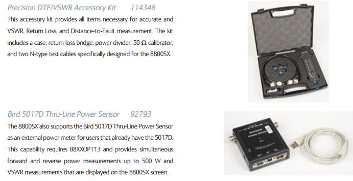
38 Antenna testing with the Tracking Generator Requires the Precision DTF / VSWR kit and Tracking Generator Power Divider Return Loss Bridge Interconnect cables Precision 50 ohm load 37


39 Return Loss Bridge hookup With the optional Soft-Sided Carrying Case, the Return Loss Bridge can be mounted for quick and easy access. Simply connect the provided N Type cables from the 8800S to the Return Loss Bridge. 1. Connect the Bridge GEN port to the 8800S GEN port. 2. Connect the Bridge ANT port to the 8800S ANT port. With the Return Loss Bridge you can measure Antenna or Device Return Loss or VSWR. Use the Power Divider to measure Distance to Fault. 38
40 Accessing the Tracking Generator screen VSWR, Return Loss plots and Distance to Fault measurements are done using the Tracking Generator mode. To access the Tracking Generator, select Tracking Gen from the Analyzers tab on the launch bar. 39


41 Configure for Return Loss / VSWR sweep Connect the Return Loss Bridge as indicated earlier. Establish the settings as indicated in the chart for Control tab 1 and Control tab 2. On Control tab 1, press the Set Ref Level button to establish a zero reference. 40

42 VSWR Sweep Connect an Antenna or device to the Return Loss Bridge DUT (Device under test) port. As configured, this will show a sweep from 100 MHz to 1 GHz. Set Y Unit to VSWR on Control Tab 1. This VSWR sweep shows good performance at higher frequencies. 41

43 Power Divider hookup With the optional Soft-Sided Carrying Case, the Power Divider can be mounted for quick and easy access. Simply connect the provided N Type cables from the 8800S to the Power Divider. 1. Connect the Divider GEN port to the 8800S GEN port. 2. Connect the Divider ANT port to the 8800S ANT port. 42

44 Measuring DTF 1. Connect the precision 50 ohm termination to the Power Divider DUT port. 2. Establish the settings as illustrated. 3. For Distance, enter a value that is longer than the expected length to be measured. 4. On the Cable tab, choose the cable type from the recall cable menu or directly enter the Velocity factor and loss per 100 ft if known. 43

45 Measuring DTF 1. Press the Calibrate button on the Control 1 tab. 2. Remove the 50 ohm termination and connect the transmission line and antenna to the DUT port of the Power Divider. 3. Markers can be used to measure the distance to the antenna. 44

46 Digital Radio Testing From the Sample Setups area, highlight the P25 Test folder and press the icon to enter the folder. 45
47 Digital Radio Testing From the P25 Tests folder, choose the P25 Loopback setup file. This file will recall the primary elements required to perform P25 Transmitter and Receiver tests. Upper and Lower limits will be configured for signals that have limits set by the technology standards. 46

48 Digital Radio Testing After the setup has recalled, enable the RF Generator on the Generator tile. The 8800S is now generating a P25 signal into itself. The TX BER, Modulation Fidelity and Symbol Deviation meters will show up as green on the Digital Demod tile as they are within the preset limits set for these meters. 47

49 Digital Radio Testing Transmitter Testing Connect a conventional P25 radio to the 8800S TR port. Turn the 8800S Generator Enable to OFF. Expand the Receiver tile and Key the transmitter. Use the Freq Find feature to find an unknown transmitter frequency or just enter the frequency on the receiver tile if the frequency is known. 48


50 Digital Radio Testing Transmitter Testing On the 8800S Digital Demod tile, set the Pattern field to FRAMESYNC to measure TX BER on a voice channel. Use the Fast Stack feature to access the Modulation tile in the upper right corner. 49
51 Digital Radio Testing Transmitter Testing Demodulated audio is not available to the speaker on the 8800S in Digital formats. Key the P25 conventional transmitter. Modulation Fidelity readings should be <5% Error. TX BER should be 0. Symbol deviation should be between 1620 Hz and 1980 Hz. Power and Frequency error should be within expected limits. Note the decoded NAC value on the Digital Demod panel as it will be programmed on the Modulation tile to test the receiver. 50

52 Digital Radio Testing Receiver Testing Unkey the transmitter and enter the decoded NAC value on the Modulation tile NAC field. On the 8800S Generator tile, enter the receiver frequency and set the Enable field to ON. A tone should be heard from the radio receiver now. The 8800S generator level can be reduced to see what level produces an unstable tone in the receiver revealing the sensitivity of the receiver. 51

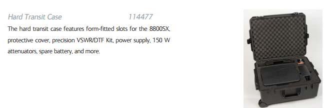
53 8800SX Options and Accessories 5
54 Questions or Comments? Contact Information For information about pricing for our products, contact the sales office by calling Cobham AvComm Sales at (800) or ing For technical/product support, calibration, maintenance and general customer service inquiries, you can contact our help desk by clicking here, calling (800) , or ing Click here for more information on the 8800SX and latest software versions and training materials. 53
8800SX DMR Repeater Test Option 06
 8800SX DMR Repeater Test Option 06 DMR Repeater Test Option The DMR Repeater test option allows testing of a DMR Repeater that is in conventional DMR Mode. Trunking or analog configurations are not supported.
Quick Site Testing with the 8800SX
 Quick Site Testing with the 8800SX Site Testing with the 8800SX Basic Tests 5 site testing involves several tests to verify site operation. NOTE: This is not intended to be a complete commissioning procedure.
8800SX Series P25 Phase II Test Option 05
 8800SX Series P25 Phase II Test Option 05 8800SX P25 Phase 2 Operation Introduction The P25 Phase 2 Option 05 allows transmitter and receiver testing of both subscriber portable and mobile radios as well
VIAVI Solutions 3550 Series Software Release Notes
 Version 2.3.1 Release Notes 7/31/2018 1. A new field for temperature has been added to Option 14 Bird Thru Line Power meter. 1. The marker frequency entries are not altered by changing the center frequency
VIAVI Solutions 8800 Series Software Release Notes
 Version 2.3.1 Release Notes 7/31/2018 1. A new field for temperature has been added to Option 13 Bird Thru Line Power meter. 1. The marker frequency entries are not altered by changing the center frequency
Testing Motorola P25 Conventional Radios Using the R8000 Communications System Analyzer
 Testing Motorola P25 Conventional Radios Using the R8000 Communications System Analyzer Page 1 of 24 Motorola CPS and Tuner Software Motorola provides a CD containing software programming facilities for
Understanding the Precision Antenna, Cable, and Power Measurements on the 3550 Radio Test System
 Application Note Understanding the Precision Antenna, Cable, and Power Measurements on the 3550 Radio Test System The Aeroflex 3550 Radio Test System now includes new methods for more accurately measuring
Application Note: Testing P25 Conventional Radios Using the Freedom Communications System Analyzers
 : Testing P25 Conventional Radios Using the Freedom Communications System Analyzers FCT-1007A Motorola CPS and Tuner Software Motorola provides a CD containing software programming facilities for the radio
Introduction to the 8800SX Tiles and Controls
 Introduction to the 8800SX Tiles and Controls Contents Menu Choose a hyperlink below I/O and Controls Generators Menu Receiver Menu Analyzers Menu Meters Menu Utilities Menu Configuration Menu Options
Installed Radio Testing with the 3500
 Application Note Installed Radio Testing with the 3500 Aeroflex has uniquely designed the Aeroflex 3500 portable radio test set for complete testing of installed radio communication systems. The 3500 is
Appendix G: IFR 8800 Test Procedures MAINTENANCE GUIDE.
 Appendix G: IFR 8800 Test Procedures MAINTENANCE GUIDE www.codanradio.com MAINTENANCE GUIDE MT-4E ANALOG & P25 DIGITAL RADIO SYSTEMS Contents Appendix G: IFR 8800 Test Procedures...1 MT-4E Testing with
Testing Motorola DMR MOTOTRBO Radios with the Cobham 3920B Radio Test Platform
 Application Note Testing Motorola DMR MOTOTRBO Radios with the Cobham 3920B Radio Test Platform The Cobham 3920B is the complete tool for anyone wishing to test Analog or Digital MOTOTRBO mobile or portable
DMR Application Note Testing MOTOTRBO Radios On the R8000 Communications System Analyzer
 DMR Application Note Testing MOTOTRBO Radios On the R8000 Communications System Analyzer April 2 nd, 2015 MOTOTRBO Professional Digital Two-Way Radio System Motorola and MOTOTRBO is registered in the U.S.
Application Note: DMR Application Note Testing MOTOTRBO Radios On the Freedom Communications System Analyzer
 : DMR Application Note Testing MOTOTRBO Radios On the Freedom Communications System Analyzer MOTOTRBO Professional Digital Two-Way Radio System Motorola and MOTOTRBO is registered in the U.S. Patent and
APX Mobile and Portable Automated Test and Alignment
 APX Mobile and Portable Automated Test and Alignment Software Updates First things first! Be sure to check that you are running the latest software versions for the 8800SX and its applications. Visit the
PC Tune PC Tune Test Procedures for 5100 Series Portable Radios
 PC Tune PC Tune Test Procedures for 5100 Series Portable Radios Part Number 002-9998-6513014 August 2008 Copyright 2006, 2007, 2008 by EFJohnson Technologies The EFJohnson Technologies logo, PC Configure,
ID-5100 User Evaluation & Test Report
 ID-5100 User Evaluation & Test Report By Adam Farson VA7OJ/AB4OJ Iss. 1, August 13, 2014. Part I: Brief User Evaluation. Introduction: This report describes the evaluation and lab test of ID-5100 S/N 05001175.
FCC ID: AXI IC: 10239A Alignment
 Introduction The VX-261 is carefully aligned at the factory for the specified performance across the frequency range specified for each version. Realignment should therefore not be necessary except in
8800SX TETRA Base Station Operation
 8800SX TETRA Base Station Operation 8800SX TETRA Base Station Test The 8800SX TETRA Base Station Test option utilizes the ETSI standard defined TETRA T1 test mode. - ETSI is the European Telecommunications
HP 8921A Cell Site Test Set. Product Note AMPS Base Station Testing
 HP 8921A Cell Site Test Set Product Note 8921-1 AMPS Base Station Testing AMPS Base Station Testing This product note describes manual operation of the HP 8921A Cell Site Test Set (or HP 8920A RF Communications
Mastr III P25 Base Station Transmitter Tune-up Procedure
 Mastr III P25 Base Station Transmitter Tune-up Procedure 1. Overview The Mastr III Base Station transmitter alignment is performed in several steps. First, the Transmit Synthesizer module is aligned to
8800S Digital Radio Test Set
 8800S Digital Radio Test Set Hybrid Bench and Field Portable Design 2015 Brochure The most important thing we build is trust 2 Cobham 8800S Digital Radio Test Set The NEW 8800S expands upon the unprecedented
Agilent 8920A RF Communications Test Set Product Overview
 Agilent 8920A RF Communications Test Set Product Overview Cut through problems faster! The Agilent Technologies 8920A RF communications test set was designed to solve your radio testing and troubleshooting
3900 Series Digital Radio Test Set DMR Option Manual. Issue-10
 EXPORT CONTROL WARNING: This document contains controlled technical data under the jurisdiction of the Export Administration Regulations (EAR), 15 CFR 730-774. It cannot be transferred to any foreign third
IC-400pro - RADIOAFICION.COM
 PROCEDURES IC-400pro - 5- PREPARATION When you adjust the contents on pages 5-5 and 5-6, SOFT- WARE, the optional CS-400PRO ADJ SOFTWARE (Rev..0 or later), *OPC- JIG CABLE (modified OPC- CLONING CABLE;
Swept Return Loss & VSWR Antenna Measurements using the Eagle Technologies RF Bridge
 Swept Return Loss & VSWR Antenna Measurements using the Eagle Technologies RF Bridge April, 2015 Page 1 of 7 Introduction Return loss and VSWR are a measure of the magnitude of a transmitted RF Signal
Application Note: Swept Return Loss & VSWR Antenna Measurements using the Eagle Technologies RF Bridge
 : Swept Return Loss & VSWR Antenna Measurements using the Eagle Technologies RF Bridge FCT-1008A Introduction Return loss and VSWR are a measure of the magnitude of a transmitted RF Signal in relation
8800SX Digital Radio Test Set
 8800SX Digital Radio Test Set Hybrid Bench and Field Portable Design 2016 Brochure The most important thing we build is trust 2 Cobham 8800SX Digital Radio Test Set The NEW 8800SX expands upon the unprecedented
FM Modulation. Accuracy. Total. Harmonics. Input Range. Frequency. Range. Deviation. Range. Modulation. Accuracy. Audio In Switchable Loads.
 Product Specification VIAVI 3550R Touch-Screen Radio Test System VIAVI Solutions General Specifications RF Signal Generator Output SSB Phase Noise 2 MHz - 1 GHz (usable from 500 khz) T/R Port: -50 to -125
Wireless Portable Radio Communications Test Set. Advanced Test Equipment Rentals ATEC (2832)
") Established 1981 Advanced Test Equipment Rentals www.atecorp.com 800-404-ATEC (2832) Wireless 3500 Portable Radio Communications Test Set Designed to dramatically improve radio operational time in vehicle
Established 1981 Advanced Test Equipment Rentals www.atecorp.com 800-404-ATEC (2832) Wireless 3500 Portable Radio Communications Test Set Designed to dramatically improve radio operational time in vehicle
Midland 248XL I NSTRUCTION GUI DE
 Midland 248XL I NSTRUCTION GUI DE INDEX Introduction...2 Function and location of the controls...3 Installation...7 Power supply...7 Installing an antenna...7 How to use your Midland 248XL...8 Frequency
Advanced Test Equipment Rentals ATEC (2832) Contents
 Contents") i Established 1981 Advanced Test Equipment Rentals www.atecorp.com 800-404-ATEC (2832) Contents Appendix B: IFR COM-120 Test Procedures...1 MT-4E Testing with the IFR COM-120 by Aerofl ex...1 General Set-Up
i Established 1981 Advanced Test Equipment Rentals www.atecorp.com 800-404-ATEC (2832) Contents Appendix B: IFR COM-120 Test Procedures...1 MT-4E Testing with the IFR COM-120 by Aerofl ex...1 General Set-Up
VIAVI 3550R. Touch-Screen Radio Test System. Product Brief
 Product Brief VIAVI 3550R Touch-Screen Radio Test System VIAVI Solutions The complete portable, on site radio communication test system for analog and digital communication systems. Now available with
3550R. Touch-Screen Radio Test System. Data Sheet. The most important thing we build is trust
 3550R Touch-Screen Radio Test Data Sheet The most important thing we build is trust The complete portable, on site radio communication test system for analog and digital communication systems. Now available
Technical Equipment Specification
 STATE OF CALIFORNIA Office of the State Chief Information Officer Public Safety Communications Division Technical Equipment Specification Equipment Type: Transmitter/Receiver Mobile Relay/Base/Control
3550R. Touch-Screen Radio Test System. Data Sheet. The most important thing we build is trust
 3550R Touch-Screen Radio Test Data Sheet The most important thing we build is trust The complete portable, on site radio communication test system for analog and digital communication systems. Now available
Guardian and DL3282 Modem Interface Technical Service Application Note
 Guardian and DL3282 Modem Interface Technical Service Application Note OVERVIEW The following document is designed to provide information for the implementation of the Guardian Wireless Modem/Analog Radio
Military Communications
 Military Communications 3515A Military Portable Radio Communications Test Set New Integrated Audio Connectors The Aeroflex 3515A was developed for military use and offers rugged construction and testing
i2820h (USA) ie2820(europe)
 ie2820(europe)") January 2007 DUAL BAND TRANSCEIVERS i2820h (USA) ie2820(europe) The above photo shows the IC-2820H. The IC-E2820 differs slightly from this photo. Icom proudly announces the debut of the new dual band
January 2007 DUAL BAND TRANSCEIVERS i2820h (USA) ie2820(europe) The above photo shows the IC-2820H. The IC-E2820 differs slightly from this photo. Icom proudly announces the debut of the new dual band
The Complete Portable, On Site Radio Communication Test System for Analog and Digital Communication Systems. Multi-Function Oscilloscope
 Wireless 3550 Touch-Screen Radio Test System The Complete Portable, On Site Radio Communication Test System for Analog and Digital Communication Systems The 3550. The first truly portable touch-screen
The Complete Portable, On Site Radio Communication Test System for Analog and Digital Communication Systems
 Wireless 3550 Touch-Screen Radio Test System The Complete Portable, On Site Radio Communication Test System for Analog and Digital Communication Systems Full Feature RF Test Functions -140 dbm DANL Spectrum
8800SX. Advanced Analog and Digital Radio Test for Both Bench and Field Test Environments. Digital Radio Test Set. Data Sheet
 8800SX Digital Radio Test Set Data Sheet The most important thing we build is trust Advanced Analog and Digital Radio Test for Both Bench and Field Test Environments The NEW 8800SX expands upon the unprecedented
DSA-815 Demo Guide. Solution: The DSA 800 series of spectrum analyzers are packed with features.
 FAQ Instrument Solution FAQ Solution Title DSA-815 Demo Guide Date:08.29.2012 Solution: The DSA 800 series of spectrum analyzers are packed with features. Spectrum analyzers are similar to oscilloscopes..
8800SX Digital Radio Test Set
 8800SX Digital Radio Test Set Hybrid Bench and Field Portable Design Brochure The most important thing we build is trust 2 Cobham 8800SX Digital Radio Test Set The NEW 8800SX expands upon the unprecedented
200GTL ALIGNMENT REVISION: 1.0 BURKE MODEL: 200GTL REVISION: 1.2 DATE: 02/14/06. Total Pages: 6 pages. Page:1 print date: 9/23/09
 ALIGNMENT PROCEDURE MODEL: 200GTL REVISION: 1.2 DATE: 02/14/06 PREPARED BY: BURKE Total Pages: 6 pages Page:1 print date: 9/23/09 1 TEST CONDITION: 200GTL ALIGNMENT INSTRUCTION 1.0. TEST TEMPERTAURE: 77
VX-2100/VX-2200 (UHF) Alignment
 Alignment") VX-2100/VX-2200 (UHF) Introduction The VX-2100/2200 is carefully aligned at the factory for the specified performance across the frequency range specified for each version. Realignment should therefore
VX-2100/VX-2200 (UHF) Introduction The VX-2100/2200 is carefully aligned at the factory for the specified performance across the frequency range specified for each version. Realignment should therefore
8800SX. Advanced Analog and Digital Radio Test Set for Bench and Field Environments. Digital Radio Test Set. Data Sheet
 8800SX Digital Radio Test Set Data Sheet The most important thing we build is trust Advanced Analog and Digital Radio Test Set for Bench and Field Environments The NEW 8800SX expands upon the unprecedented
Yaesu FT-8800R Alignment
 DUAL BAND FM TRANSCEIVER Introduction and Precautions The FT-8800R has been carefully aligned at the factory for the specified performance across the 144 MHz and 430 MHz amateur bands. Realignment should
CS3000 ALIGNMENT REFERENCE MANUAL FM HANDHELD TRANCEIVER. Connect Systems Incorporated 1802 Eastman Ave., Suite 116 Ventura CA Version 1.
 CS3000 ALIGNMENT REFERENCE MANUAL FM HANDHELD TRANCEIVER Connect Systems Incorporated 1802 Eastman Ave., Suite 116 Ventura CA 93003 Version 1.00 Copyright 2010 by Connect Systems Incorporated TABLE OF
Signal Generators for Anritsu RF and Microwave Handheld Instruments
 Measurement Guide Signal Generators for Anritsu RF and Microwave Handheld Instruments BTS Master Spectrum Master Tracking Generator Option 20 Vector signal Generator Option 23 Anritsu Company 490 Jarvis
Microphone audio, from the MFJ-1278B to your transmitter. Ground, audio and PTT common. Push-to-talk, to allow the MFJ-1278B to key your transmitter.
 Computer interfacing, covered in the previous chapter, is only half the interfacing task. The other half is connecting your MFJ-1278B to your radios. MFJ-1278B Radio Ports Interfacing the MFJ-1278B to
Application Note. Understanding PassPort Radio Systems
 Application Note Understanding PassPort Radio Systems PassPort radio systems are being widely used in the United States and other countries. Learn about this technology and how to test PassPort with an
Test Equipment Solutions Datasheet
 Test Equipment Solutions Datasheet Test Equipment Solutions Ltd specialise in the second user sale, rental and distribution of quality test & measurement (T&M) equipment. We stock all major equipment types
Keysight MOI for MIPI D-PHY Conformance Tests Revision Oct, 2014
 Revision 1.10 10-Oct, 2014 Keysight Method of Implementation (MOI) for MIPI D-PHY Conformance Tests Using Keysight E5071C ENA Network Analyzer Option TDR 1 Table of Contents 1. Modification Record... 4
ATB-7300 to NAV2000R Product Comparison
 ATB-7300 to NAV2000R Product Comparison Aeroflex Aeroflex Parameter / Function ATB-7300 NAV2000R Collins 479S-6A simulation Yes Yes ARINC 410 Auto-Tune Compatible No Yes Signal Generator Frequency Freq
8800SX. Advanced Analog and Digital Radio Test Set for Bench and Field Environments. Digital Radio Test Set. Data Sheet
 8800SX Digital Radio Test Set Data Sheet The most important thing we build is trust Advanced Analog and Digital Radio Test Set for Bench and Field Environments The 8800SX expands upon the unprecedented
FREEDOM Communications System Analyzer R8600 DATA SHEET
 FREEDOM Communications System Analyzer R8600 DATA SHEET Table of Contents Operating/Display Modes 3 General 3 Generator (Receiver Test) 4 Receiver (Transmitter Test) 5 Spectrum Analyzer 6 Oscilloscope
Cable and Antenna Analyzer
 Measurement Guide Cable and Antenna Analyzer for Anritsu s RF and Microwave Handheld Instruments BTS Master Anritsu Company 490 Jarvis Drive Morgan Hill, CA 95037-2809 USA http://www.anritsu.com Part Number:
Screen shots vary slightly according to Windows version you have.
 http://www.w1hkj.com/fldigihelp/audio_adjust_page.html Screen shots vary slightly according to Windows version you have. Receive audio Setting the correct hardware, operating system, and fldigi received
CS2010 AND CS2011 ALIGNMENT REFERENCE MANUAL FM HANDHELD TRANCEIVER. Connect Systems Incorporated 1802 Eastman Ave., Suite 116 Ventura CA 93003
 CS2010 AND CS2011 ALIGNMENT REFERENCE MANUAL FM HANDHELD TRANCEIVER Connect Systems Incorporated 1802 Eastman Ave., Suite 116 Ventura CA 93003 Version 1.01 Copyright 2009 by Connect Systems Incorporated
FREEDOM Communications System Analyzer R8000C DATA SHEET
 FREEDOM Communications System Analyzer R8000C DATA SHEET Table of Contents Operating/Display Modes 3 General 3 Generator (Receiver Test) 4 Receiver (Transmitter Test) 5 Spectrum Analyzer 6 Oscilloscope
Agilent MOI for MIPI D-PHY Conformance Tests Revision 1.00 Dec-1, 2011
 Revision 1.00 Dec-1, 2011 Agilent Method of Implementation (MOI) for MIPI D-PHY Conformance Tests Using Agilent E5071C ENA Network Analyzer Option TDR 1 Table of Contents 1. Modification Record... 4 2.
2801 Multilock. Communications System Analyzer. Data Sheet. Boosting wireless efficiency
 Data Sheet 2801 Multilock Communications System Analyzer Boosting wireless efficiency A real multi-talented instrument the Willtek 2801 Multilock The Willtek 2801 Multilock is a test instrument for multiple
EDACS WALL MOUNT STATION. Maintenance Manual. Mobile Communications LBI-31838A TABLE OF CONTENTS
 A Mobile Communications EDACS WALL MOUNT STATION TABLE OF CONTENTS SYSTEM BOARD & REGULATOR BOARD.......... LBI-31892 KEY/DISPLAY BOARD MAINTENANCE MANUAL.... LBI-31940 Maintenance Manual Printed in U.S.A.
Receiver Adjustments
 ! -8-4!5 This Section details procedures for tuning and adjustment of T2000 series II radios. This is normally only required during product manufacture or after major servicing. The following topics are
S5101 Handheld Radio Communication Analyzer
 is the ideal radio tester for laboratory, production, service and maintenance use. It combines radio frequency emission, reception analysis, audio source, analyzer, etc. all into one unit. It can measure
Yaesu FT-25R 2-Meter Handheld Transceiver
 Yaesu FT-25R 2-Meter Handheld Transceiver Reviewed by Dan Wall, W1ZFG ARRL LoTW Administration w1zfg@arrl.org The latest entry into the field of small, inexpensive handhelds is the Yaesu FT-25R. This is
Introduction Pag. 1. Function and location of the controls Pag. 2. Installation Pag. 3. Power supply Pag. 3. Installing an antenna Pag.
 ALAN 121 INDEX Introduction Pag. 1 E N G L I S H Function and location of the controls Pag. 2 Installation Pag. 3 Power supply Pag. 3 Installing an antenna Pag. 4 How to operate with your transceiver Pag.
TECHNICAL NOTES MT-4 Radio Systems TN182 Battery Level Reporting and Remote P25 Test Tone
 Battery Level Reporting is a method of activating a repeater remotely to have it transmit a signal that reports the battery voltage level over RF. The Remote P25 Test Tone is a remotely activated Standard
HR1200. Version 1.00 ATIM RADIOCOMMUNICATION 1/11
 HR1200 Version 1.00 ATIM RADIOCOMMUNICATION 1/11 Contact Information ATIM RADIOCOMMUNICATION Les guillets 38250 Villard de Lans France Tel : +33 (0)4 76 95 50 65 Fax: +33 (0)4 76 95 50 64 Web : www.atim.com
FREEDOM Communications System Analyzer R8100 DATA SHEET
 FREEDOM Communications System Analyzer R8100 DATA SHEET Table of Contents Operating/Display Modes 3 General 3 Generator (Receiver Test) 4 Receiver (Transmitter Test) 5 Spectrum Analyzer 6 Oscilloscope
TV SIGNAL LEVEL METER USER MANUAL
 TV SIGNAL LEVEL METER USER MANUAL - 0 - 1. Overview (1) (1) RF input (2) (3) A D E B C (2) Speaker (3) LCD display (4) Charger indicator (5) RS232 communication port (6) DC-IN port F G A. The battery icon
GC723A / GC724B Cable and Antenna Analyzer
 www.gctm.net GC723A / GC724B Cable and Antenna Analyzer GC723A / GC724B Cable and Antenna Analyzer Introduction A large number of abnormal cell site problems are typically caused by the antenna system,
Studio Broadcast System
 SET UP and USE 1. REGULATORY AND COMPLIANCE STATEMENTS... 3 2. OVERVIEW 2.1 Core Performance Targets 2.2 Specifications 2.3 System Components 2.4 System Block Diagram 3. BP24 UWB BODY PACK TRANSMITTER...
FT-897 Alignment. Local Oscillator Adjustment. PLL Adjustment
 FT-897 Local Oscillator Adjustment Reference Frequency Adjustment a. Connect a frequency counter to TP1032. b. Adjust the trimmer capacitor (TC5001) for 67.875000MHz ±5Hz on the frequency counter. c. Connect
Radio Communications Series Portable Radio Communications Test Set
 Radio Communications 3515 Series The most important thing we build is trust Features and Functions Reduces No Fault Found cost - find broken components and faulty installations at the source, reducing
EVM option allows for true transmitter alignment
 Since 1976, Aeroflex has provided cutting-edge test solutions to the mobile radio industry. Aeroflex carries on that tradition with the IFR 2975 Radio Test Set. It's a test solution designed from the ground
VHF Transceiver AR6201
 VHF Transceiver AR6201 Operating Instructions Issue 2 / October 2010 Article No. 0618.764-071 Becker Flugfunkwerk GmbH Baden-Airpark B 108 77836 Rheinmünster Germany Telefon / Telephone +49 (0) 7229 /
LD5 CW/SSB QRP Transceiver SDR /DSP
 LD5 CW/SSB QRP Transceiver SDR /DSP Quick guide manual Description: At the development base of the digital signal processing unit, an algorithm is embedded for IQ processing of the channels with phase
Agilent MOI for MIPI M-PHY Conformance Tests Revision Mar 2014
 Revision 1.10 20 Mar 2014 Agilent Method of Implementation (MOI) for MIPI M-PHY Conformance Tests Using Agilent E5071C ENA Network Analyzer Option TDR 1 Table of Contents 1. Modification Record... 4 2.
LnR Precision, Inc. 107 East Central Avenue, Asheboro, NC
 LD5 CW/SSB QRP Transceiver Quick guide manual Description: At the development base of the digital signal processing unit, an algorithm is embedded for IQ processing of the channels with phase suppression
Wireless Analog and Digital Radio Test Set. Hybrid Bench and Portable Radio Test System for Complete Testing of Analog and Digital Radios
 Wireless 8800 Analog and Digital Radio Test Set Hybrid Bench and Portable Radio Test System for Complete Testing of Analog and Digital Radios Standing on 50 years of experience and leadership in radio
Adjustment for IC-910H. Adjustment. Adjustment
 for IC-910H 30.2 MHz Level 430MHz 2 nd Lo (60.4MHz) Peak Setting the 60.4MHz Frequency the144mhz 1 st Lo Lock Voltage th430mhz 1 st Lo Lock Voltage 144MHz RX Peak/ Gain Band Peak Band Total Gain Sub- Band
Successful mobile-radio tester now with US TDMA and AMPS standards
 Universal Radio Communication Tester CMU200 Successful mobile-radio tester now with US TDMA and AMPS standards Digital TDMA standard TDMA (time-division multiple access) is a mobile-radio system based
Measuring Frequency Settling Time for Synthesizers and Transmitters
 Products: FSE Measuring Frequency Settling Time for Synthesizers and Transmitters An FSE Spectrum Analyser equipped with the Vector Signal Analysis option (FSE-B7) can measure oscillator settling time
Appendix C: IFR 3920 Test Procedures MAINTENANCE GUIDE.
 ppendix C: IFR 20 Test Procedures MINTENNCE GUIDE www.codanradio.com MINTENNCE GUIDE MT-4E NLOG & P2 DIGITL RDIO SYSTEMS Contents ppendix C: IFR 20 Test Procedures...1 MT-4E Testing with the IFR 20 by
LBI-31564A. Mobile Communications. DELTA - SX MHz RADIO COMBINATIONS (NEGATIVE GROUND ONLY) Maintenance Manual
 Maintenance Manual") A Mobile Communications DELTA - SX 136-174 MHz RADIO COMBINATIONS (NEGATIVE GROUND ONLY) Maintenance Manual TABLE OF CONTENTS MILITARY AND SYSTEM SPECIFICATIONS................................. 2-3 COMBINATION
A Mobile Communications DELTA - SX 136-174 MHz RADIO COMBINATIONS (NEGATIVE GROUND ONLY) Maintenance Manual TABLE OF CONTENTS MILITARY AND SYSTEM SPECIFICATIONS................................. 2-3 COMBINATION
Localizer provides signal generation over the Localizer band of to MHz with 90 Hz and 150 Hz tones, amplitude modulated
 The IFR 4000 verifies the operation and installation of ILS, VOR and Marker Beacon receivers and VHF/UHF AM/FM and HF AM/SSB transceivers. The IFR 4000, with its lightweight size (under 8 lbs.), long run
Measurement Procedure & Test Equipment Used
 Measurement Procedure & Test Equipment Used Except where otherwise stated, all measurements are made following the Electronic Industries Association (EIA) Minimum Standard for Portable/Personal Land Mobile
UHF Wireless Microphone System
 PDWM1902 PDWM1904 PDWM3375 PDWM3378 PDWM3400 UHF Wireless Microphone System SYSTEM TYPE The Vocal Artist-UHF is a hand-held system designed for singers who desire the high quality microphones and the freedom
AA-35 ZOOM. RigExpert. User s manual. Antenna and cable analyzer
 AA-35 ZOOM Antenna and cable analyzer RigExpert User s manual . Table of contents Introduction Operating the AA-35 ZOOM First time use Main menu Multifunctional keys Connecting to your antenna SWR chart
3900 Series Digital Radio Test Set. NXDN Remote Programming Manual Issue-8
 EXPORT CONTROL WARNING: This document contains controlled technical data under the jurisdiction of the Export Administration Regulations (EAR), 15 CFR 730-774. It cannot be transferred to any foreign third
ELECRAFT KX3 EXTENDED VFO TEMPERATURE COMPENSATION PROCEDURE Copyright 2012 Elecraft LLC Rev. A9, November 14, 2012
 ELECRAFT KX3 EXTENDED VFO TEMPERATURE COMPENSATION PROCEDURE Copyright 2012 Elecraft LLC Rev. A9, November 14, 2012 Introduction The KX3 standard VFO temperature compensation is entirely adequate for most
RMV25 / RMV50 RMU25 / RMU45
 RMV25 / RMV50 RMU25 / RMU45 Owner's Manual TABLE OF CONTENTS INTRODUCTION... 3 FCC Requirements... 3 SAFETY WARNING INFORMATION... 3 CONTROLS and INDICATORS... 5 FRONT PANEL... 5 LCD Icons and Indicators...
AUTOTUNE USER GUIDE. R8000 Series Communications Systems Analyzer. Motorola ASTRO XTL Series Motorola ASTRO XTS Series
 R8000 Series Communications Systems Analyzer AUTOTUNE USER GUIDE Motorola ASTRO XTL Series Motorola ASTRO XTS Series Freedom Communication Technologies 2002 Synergy Blvd, Suite 200 Kilgore, Texas 75662
Disable Windows Sounds
 9/28/2017 - K3CT Disable Windows Sounds Users may want to disable the Windows Sounds so none of the Windows OS sounds are transmitted on the radio. Install the Icom Drivers, Select COM port, Disable Power
TY96 and TY97 VHF Radio Operating Manual
 TY96 and TY97 VHF Radio Operating Manual 01239-00-AA 18 February 2016 Trig Avionics Limited Heriot Watt Research Park Riccarton, Edinburgh EH14 4AP Scotland, UK Copyright 2016 EN Trig Avionics Limited
JD723A/JD724B/JD726A Cable and Antenna Analyzers
 COMMUNICATIONS TEST & MEASUREMENT SOLUTIONS JD723A/JD724B/JD726A Cable and Antenna Analyzers Key Features Portable and lightweight handheld instrument. Built in wireless frequency bands as well as the
BUXCOMM 2007 RASCAL GLX OPERATOR S MANUAL Before we begin, let s perform the initial setup:
 BUXCOMM 2007 RASCAL GLX OPERATOR S MANUAL Before we begin, let s perform the initial setup: Sound Card CONFIGURATION: Most soundcards use 3.5mm (1/8") jack for line and/or microphone input. Use the LINE
WIRES-X Portable Digital Node Function. Instruction Manual
 Wide-Coverage Internet Repeater Enhancement System WIRES-X Portable Digital Node Function Instruction Manual Please read this Instruction Manual carefully for appropriate procedure. Preparation Procedure