TEST REPORT MOBILE MICROWAVE VIDEO TRANMITTER FCC ID: FC3HDX2025D MODEL: HDX-1100S. APPLICANT: VISLINK, Inc. May 7, 2013 PAGE 1 OF 33
|
|
|
- Daniel Beasley
- 5 years ago
- Views:
Transcription
1 TEST REPORT MOBILE MICROWAVE VIDEO TRANMITTER FCC ID: FC3HDX2025D MODEL: HDX-1100S APPLICANT: VISLINK, Inc. May 7, 2013 PAGE 1 OF 33
2 TABLE OF CONTENTS Section 1 INTRODUCTION 3 APPLICATION 4 TECHNICAL DATA SUMMARY 5 TECHNICAL DISCRIPTION EMISSIONS DESIGNATORS 5 Section 2 MEASUREMENTS 6-20 RF Power Output Modulation Characteristics Occupied Bandwidth Spurious Emissions at Antenna Terminals Field Strength of Spurious Radiation Frequency Stability Section 3 QUALITY DECLARATION 21 NQA CERTIFICATE Fig.2 Section 4 TRANSMITTER DESCRIPTIONS / PHOTOS Section 5 TEST STATION SETUP Section 6 MPE CALCULATIONS Section 7 TEST FACILITIES AND COMPLIANCE DIRECTIVE 31 Section 8 RADIO CHARACTERISTICS 32 Section 9 LABEL INFORMATION 33 PAGE 2 OF 33
3 SECTION 1 INTRODUCTION GENERAL INFORMATION Applicant: Vislink, Inc. 101 Billerica Avenue, Building 6 North Billerica, MA Tel Attn: Sal Blatti, Compliance Manager sal.blatti@vislink.com FCC ID: Installation and Operating Manual: Equipment Description: Block Diagram: Equipment model: Frequency Range: FCC Part numbers: FC3HDX2025D HDX-1100 User and Technical Manual attached Mobile Video Transmitter see below See Technical Description, below HDX-1100S MHz 74; subpart F: (a)(1), (a)(2), (a)(3). 78; subpart D, , , , ; subpart B, 90.2 Frequency Tolerance: % Emission Designators: 10M00D7W, 12M00D7W, 17M00D7W The data provided in this document will show that the Vislink/Microwave Radio Communications HDX1100S transmitter is in compliance with 47 CFR Parts 74, 78 and 90 for use by eligible Broadcast Auxiliary, CARS, and Private Operational Fixed Point-to-Point Radio Service licensees in the MHz mobile band as provided for in the relevant FCC part number referenced above. Radiated emission tests were conducted by Intertek Testing Services in their laboratory facility in Boxborough, MA, while the part 74, 78 and 90 emission testing was conducted in the Vislink/Microwave Radio Communications facility in North Billerica, MA. The HDX1100S was designed to comply with applicable technical regulations of 74 subpart F, 78 subpart D, and 90 subpart F for the transmission of video, audio, and data by a mobile transmitter. Typical applications may include surveillance, command center operations, emergency restoration, broadcast remote and news gathering, cable TV remote and news gathering, or other video, voice and data requirements as deemed necessary and appropriate for a specific task assignment. PAGE 3 OF 33
4 Technical Description: The HDX1100 FC3HDX2025D is a compact, mobile transmitter, designed to be adaptable to a wide range of field applications; particularly those requiring ruggedized, vehicular mounted equipment. The transmitter accepts a wide range of SMPTE based video input signals, including HD-SDI, SDI, ASI, and NTSC. Raw video, audio, and data are delivered to an integral MPEG-2 Encoder which feeds a COFDM-DVB-T modulator, operating in the 2K carrier mode, to produce a 1705 carrier spectrum. I and Q outputs of the COFDM modulator are supplied directly to an RF generator and up-converted to the operating band from 2000 to 2500 MHz at an RF power level of +20dBm. A 20 db gain RF amplifier follows the exciter to boost the final RF output power to + 40dBm (10.0 Watt). The exciter RF drive level is factory set to limit the RF output from the PA to 10 Watt for part 74 and 78 or 5W for part 90 Web browser interface Composite in ASI Input Video Switch RF Exciter RF AMP RF Out SDI/HD-SDI in I-Q MPEG2 Encoder & COFDM Modulator Control & DC Distribution Front Panel VDC In Remote Panel/ RS-232 Mgmt HDX1100 Functional Block Diagram PAGE 4 OF 33
5 The specific operating frequency is determined by a high stability wide band VCO. The VCO set-up voltage is controlled by a microprocessor that is factory programmed to provide channel plans in accordance with the rules as specified in part 74, 78, or 90. Channel Center Frequency (MHz) Table 1 - HDX-1100S Factory channel plan center frequencies Digital modulation of the COFDM carriers changes between QPSK, 16QAM, and 64QAM as determined by user bit rate requirements. The symbol rate is set to maintain the occupied bandwidth mask to be in compliance with the ETSI EN V1.51 standards for either a 6 or 8 MHz COFDM pedestal and to be in compliance with the emission bandwidth limits as required in (a)(2)(i), (e). An LCD touch screen display located on the front panel of the transmitter is used to control basic transmission parameters and provide operational status of internal systems. The transmitter can also be operated from an external remote panel via hard wired RS-232 link. Additional information may be found in the HDX-1100 User and Technical Manual, included with this application. PAGE 5 OF 33
6 SECTION 2 - MEASUREMENTS TECHNICAL DATA SUMMARY Frequency band: Operating frequency range is MHz Modulation Type: COFDM; QPSK, 16QAM, 64QAM. Licensed for: Broadcast Auxiliary Service under CFR 47 part 74: subpart F Cable Television Relay Service under CFR 47 part 78: subpart D PRIVATE LAND MOBILE RADIO SERVICES under CFR 47 part 90: subpart B Channel spacing: 10, 12 or 17 MHz (see section 1.0 for details) FCC ID: FC3HDX2025D Equipment Description: Mobile Video Transmitter Equipment model: HDX-1100S Frequency Tolerance: % Emission Designators: 10M00D7W, 12M00D7W, 17M0D7W RF Power Output Measurement per Applicable specifications: 12 Watts (+ 40.8dBm) per (a) 20 Watts (+ 43dBm) per (a) 5 Watts (+ 37dBm) per (o) The RF power measured 10, 12 and 17 MHz channels, as required for this application, is shown below: Frequency (MHz) Transmit Power Conducted (part 74 and 78) Channel Bandwidth dBm (9.3W) 12 MHz dBm (9.1W) 12 MHz dBm (9.3W) 12 MHz dBm (8.7W) 12 MHz dBm (8.7W) 12 MHz dBm (8.6W) 12 MHz dBm (8.7W) 12 MHz dBm (9.5W) 17 MHz dBm (9.3W) 17 MHz dBm (10W) 17 MHz PAGE 6 OF 33
7 Frequency (MHz) Transmit Power Conducted (part 90) 36.6dBm (4.5W) 36.5dBm (4.4W) 36.8dBm (4.8W) Table 2 Power measurement Channel Bandwidth 10 MHz 10 MHz 10 MHz EUT Coupler Power Meter Spectrum Analyzer A Figure 1 - Test Setup for Power Measurements PAGE 7 OF 33
8 SECTION 2 MODULATION CHARACTERISTICS PER Applicable Specification: None Measurement Frequency: MHz Data: The unit under test is designed to be modulated by a combination of digital video, audio, and auxiliary data. The COFDM modulated spectrum shown in the image below shows compliance with the 8 MHz pedestal option in the DVB-T standard for the 2K carrier mode, per ETSI EN V1.51. These carriers may be modulated in QPSK, 16QAM, or 64 QAM formats with no change in occupied bandwidth, as the symbol rate is fixed to maintain the same bandwidth. PAGE 8 OF 33
9 SECTION 2 - OCCUPIED BANDWIDTH To measure the occupied bandwidth, the equipment was set up as shown below, and the transmitter was modulated with a digital COFDM pedestal of 7.61MHz (8MHz). The output of the transmitter was viewed on a spectrum analyzer. The current COFDM standard adopted by Vislink is the ETSI EN V1.2.1 ( ) for framing structure, channel coding and modulation. Since the spectrum is digitally modulated, at the center frequency, calculations where performed by establishing a reference at FO ( MHz) and the amplitude readings where calculated from a CW signal input to the transmitter. 10 MHz Occupied Bandwidth with 8MHz COFDM Pedestal EUT Coupler Power Meter Spectrum Analyzer Figure 3 - Test Setup for Emission Mask, Occupied Bandwidth, and Spurious Emission Measurements PAGE 9 OF 33
10 SECTION 2 SPURIOUS EMISSIONS AT THE ANTENNA TERMINAL: Applicable Specifications: (a)(2)(i) On any frequency removed from the assigned frequency above 250% of the authorized bandwidth: 80 db or log (P) w, whichever is the lesser attenuation. The Antenna conducted spurious emissions test were performed with the transmitter frequency set to MHz, and with a measured output power of 8.4W (+39.2dBm). The spectrum analyzer was first tuned to a reference carrier level at the fundamental operating frequency. The output spectrum was then slowly scanned from 90KHz to 27GHz. Special attention was given to those frequencies that correspond to the possible harmonic and sub harmonics. HDX1100 (S Band) 12MHz Spurious Emission Plot RF Power = 39.2dBm / 8.4W NOTE: Display db represents the spurious limit. PAGE 10 OF 33
11 The FCC limits for Spurious emissions conducted at the antenna port per CFR has been met. Applicable Specifications: On any frequency removed from the assigned frequency above 250% of the authorized bandwidth: 50 db or log (P) w, whichever is the lesser attenuation. The Antenna conducted spurious emissions test were performed with the transmitter frequency set to MHz, and with a measured output power of 5W (+37dBm). The spectrum analyzer was first tuned to a reference carrier level at the fundamental operating frequency. The output spectrum was then slowly scanned from 90KHz to 27GHz. Special attention was given to those frequencies that correspond to the possible harmonic and sub harmonics. HDX1100 (S Band) 12MHz Spurious Emission Plot RF Power = 37dBm / 5W NOTE: Display -57dB represents the spurious limit. The FCC limits for Spurious emissions conducted at the antenna port per CFR has been met. PAGE 11 OF 33
12 SECTION 2 CONTINUED- EMISSION MASK PER Applicable Specifications: (a)(2)(i) (i) For operating frequencies below 15 GHz, in any 4 KHz band, the center frequency of which is removed from the assigned frequency by more than 50 percent up to and including 250 percent of the authorized bandwidth: As specified by the following equation but in no event less than 50 decibels: A = (P - 50) + 10 Log10 B. (Attenuation greater than 80 decibels or to an absolute power of less than -- 13dBm/1MHz is not required.) where: A = Attenuation (in decibels) below the mean output power level. P = Percent removed from the center frequency of the transmitter bandwidth. B = Authorized bandwidth in MHz HDX1100 (S Band Channel 1) 12MHz Emission Plot: RF Power = 38.8dBm / 7.6W PAGE 12 OF 33
13 HDX1100 (S Band Channel 7) 12MHz Emission Plot: RF Power = 39.2dBm / 8.4W HDX1100 (S Band Channel 10) 12MHz Emission Plot: RF Power = 39.6dBm / 9.1W PAGE 13 OF 33
14 HDX1100 (S Band Channel 8) 17MHz Emission Plot: RF Power = 39.8dBm / 9.5W HDX1100 (S Band Channel 9) 17MHz Emission Plot: RF Power = 39.7dBm / 9.3W PAGE 14 OF 33
15 HDX1100 (S Band Channel 10) 17MHz Emission Plot: RF Power = 40dBm / 10W PAGE 15 OF 33
16 SECTION 2 CONTINUED- EMISSION MASK PER Applicable Specifications: (c) (c) Emission Mask C. For transmitters that are not equipped with an audio low-pass filter, the power of any emission must be attenuated below the unmodulated carrier output power (P) as follows: (1) On any frequency removed from the center of the authorized bandwidth by a displacement frequency (f d in khz) of more than 5 khz, but not more than 10 khz: At least 83 log (f d /5) db; (2) On any frequency removed from the center of the authorized bandwidth by a displacement frequency (f d in khz) of more than 10 khz, but not more than 250 percent of the authorized bandwidth: At least 29 log (f d 2 /11) db or 50 db, whichever is the lesser attenuation; (3) On any frequency removed from the center of the authorized bandwidth by more than 250 percent of the authorized bandwidth: At least log (P) db. HDX1100 (S Band Channel 8) 10MHz Emission Plot: RF Power = 36.6dBm / 4.5W PAGE 16 OF 33
 10MHz Emission Plot: RF Power = 36.8dBm / 4.")
17 HDX1100 (S Band Channel 9) 10MHz Emission Plot: RF Power = 36.5dBm / 4.4W HDX1100 (S Band Channel 10) 10MHz Emission Plot: RF Power = 36.8dBm / 4.8W PAGE 17 OF 33
18 SECTION 2 - FREQUENCY STABILITY OVER TEMPERATURE & VOLTAGE The HDX1100S TRANSMITTER (FC3HDX2025D) was set-up to transmit CW signal. The measurement was made at the antenna port using a microwave frequency counter. Measurements were made to determine the transmitter frequency stability over the temperature range -20º C to +50 ºC. The transmitter was allowed to stabilize a minimum of 30 minutes before measurement. Measurements were also made to determine transmitter frequency stability versus primary supply variation of the DC input voltage range of 18V to 36V. The Measurement Frequency was MHz Temperature Measure Frequency (Hz) (PPM) (%) -20º C º C º C º C º C º C º C º C Voltage Measure Frequency (Hz) (PPM) (%) PAGE 18 OF 33
19 Temperature Chamber EUT Frequency Counter Power supply Figure 4 - Test Setup for Frequency Stability Measurements PAGE 19 OF 33


20 SECTION 2 - FIELD STRENGTH OF SPURIOUS RADIATION The case radiated spurious emission tests were conducted by Curtis-Straus a Bureau Veritas Company, located in Littleton, Massachusetts. The HDX1100S was set-up in a 3m anechoic chamber, all cables connected and was transmitting at normal RF power. This report represents spurious emissions observed and calculated to be acceptable according to rule part: and FCC Part 15, subpart B. PAGE 20 OF 33
21 SECTION 3 - QUALITY DECLARATION QUALITY SYSTEM ISO 9000 PAGE 21 OF 33
22 SECTION 4 TRANSMITTER DESCRIPTION The HDX-1100S Mobile Digital Video Transmitter is a lightweight and rugged unit that is suited for mobile and aircraft environments; where constant vibration, shock, temperature swings, and humidity are expected. Common applications include live video feeds for law enforcement, fire, public safety and other agency surveillance tasks. The HDX-1100 includes an H.264/MPEG-4 encoder to provide standard or high definition video (SD or HD), using DVB-T/ COFDM in the 2K carrier mode. Video inputs may be SD or HD in NTSC or PAL formats, plus two audio signals and an RS-232 data channel. The amplifier operates at 5 or 10W in the high power mode, or 2W in the low power mode. The HDX-1100 includes a touch screen maintenance interface or an optional remote panel (RCU). Service personnel may configure the transmitter module with a PC using a web browser. Rear View Front View HDX1100 TX BOARD LEVEL SCHEMATICS Note: The board level schematics have been submitted as an attachment PAGE 22 OF 33

23 SECTION 4 TRANSMITTER PHOTOS FC3HDX20252D HDX1100 TRANSMITTER PHOTOS MANUFACTURERS PART # FC3HDX2025D FRONT PANEL VIEW PAGE 23 OF 33


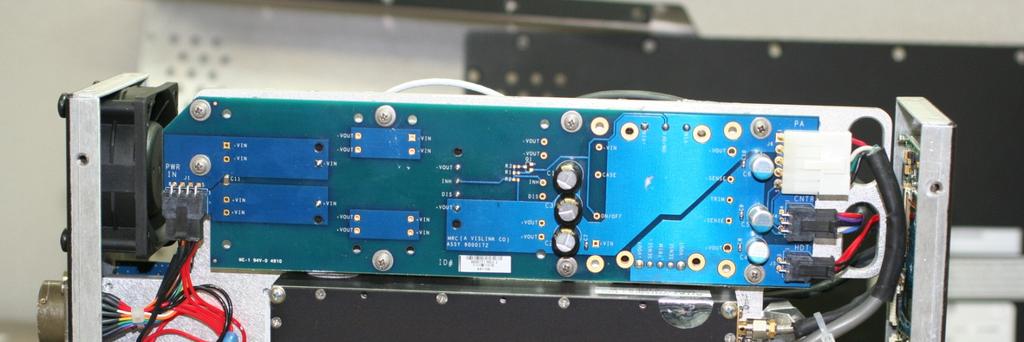
24 FC3HDX2025D INTERNAL VIEW (Modulator side) MPEG-2 Encoder Modulator / H264 Encoder Controller Board PAGE 24 OF 33
25 FC3HDX2025D INTERNAL VIEW (Power Amp side) Power Amp Power Supply PAGE 25 OF 33


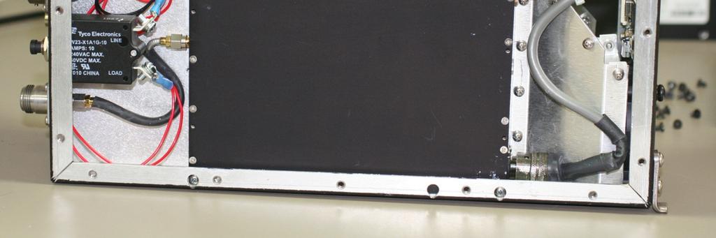
26 FC3 HDX2025D REAR VIEW RF OUTPUT CONNECTOR PAGE 26 OF 33

27 SECTION 5 - TEST SET UP PHOTOS TEST EQUIPMENT LIST MODEL SERIAL # DESCRIPTION MANUFACTURER FLK THERMOMOTER FLUKE E4419B MY POWER METER HP 8481B POWER SENSSOR HP T30C TEMP. CHAMBER TENNEY FLK MULTIMETER FLUKE 5350B FREQ. COUNTER HP E4407B MY SPECTRUM ANALYZER HP PAGE 27 OF 33

28 PAGE 28 OF 33
29 SECTION 6 MPE CALCULATIONS 6 Operating in Safety Guidelines for safe operation are derived from OET bulletin 65, August 1997, as recommended by the Federal Communications Commission (FCC). WARNING High levels of RF power are present in the unit. Exposure to RF or microwave power can cause burns and may be harmful to health. Remove power from the unit before disconnecting any RF cables and before inspecting damaged cables and/or antennas. Avoid standing in front of high gain antennas (such as a dish antenna) and never look into the open end of a waveguide or cable where RF power may be present. The HDX-1100, operated without an antenna will not create RF energy exceeding 1.0 mw/cm 2, the FCC limit for exposure. Connecting an antenna to the unit greatly enhances the potential for harmful exposure, and you must maintain a certain distance from the radiator. The following table shows the Maximum Permissible Exposure (MPE) safe distances from the antenna when operating at normal RF power level (10W). Antenna Gain (dbi) Safe Distance (cm) Safe Distance (in) Note Hazardous RF radiation limits and recommended distances may vary by country. Observe all applicable state and federal regulations when using this transmitter. To perform calculations to understand the safe exposure margin (MPE), use the following formula suggested by OET 65. The calculations provided are for common antennas often used in the mobile microwave environment. Calculating MPE EIRP = P * (10 ^ (G / 10)) = (antilog of G/10) * P P = RF power delivered to the antenna in mw G = Power gain of the antenna in the direction of interest relative to an isotropic radiator R = distance to the center of radiation of the antenna in centimeters S = MPE in mw/cm² (milliwatts per square centimeters) Conversions dbi to numeric gain = Antilog (dbi/10) Feet to centimeters = Feet * Centimeters to Feet = cm * π = PAGE 29 OF 33
30 User Input RF power delivered to the antenna = Watts Antenna gain (referenced to isotropic antenna) = dbi Distance from the center of radiation = Feet Calculation steps: 1. [P] RF power input. Watts to milliwatts = Watts * [G] Antenna gain dbi. Numeric gain = Antilog (dbi/10) 3. [EIRP] Multiply P * G 4. [R] Centimeters to feet = Centimeters * Square R 6. Multiply R² * 4π 7. [S] Divide (R² * 4π) into EIRP S = Power Density in milliwatts per square centimeters. Note At frequencies above 1500 MHz, S must not be greater than 1. Reference FCC OET Bulletin 65, August Evaluating Compliance with FCC Guidelines for Human Exposure to Radio Frequency Electromagnetic Fields Vislink, in accordance with the requirements set forth by the FCC, provides this information as a guide to the user and assumes the users of this equipment are licensed and qualified to operate the equipment per the guidelines and recommendations contained within the product user guides and in accordance with any FCC rules that may apply. PAGE 30 OF 33
31 SECTION 7 TEST FACILITIES TEST FACILITIES: Vislink / MICROWAVE RADIO COMMUNICATIONS Billerica Avenue N. Billerica, MA Curtis-Straus a Bureau Veritas Company One Distribution Center Circle Littleton, MA Prepared by: Sal Blatti Compliance Manager THE MANUFACTURER HEREBY DECLARES THAT IT WILL TAKE ALL MEASURES TO INSURE THE COMPLIANCE OF THE PRODUCT DETAILED IN THIS TECHNICAL FILE WITH THE FCC Sal Blatti Compliance Manager PAGE 31 OF 33
32 SECTION 8 - RADIO CHARACTERISTICS RF SPECIFICATIONS The RF specifications of the HDX1100 will be as follows: RF OUTPUT Connector: Type N female Impedance: 50 Ohms Return loss: 17 db minimum (output) Output stability: ± 1.0 db, - 20 o to + 55 o C Harmonics: 60 dbc PA protection: Capable of operation into infinite VSWR, no time limit. Frequency Step Size: 250 KHz RF power output: 10W (part 74 and 78) RF power output: 5W (part 90) INPUT POWER DC Voltage: VDC DC Power: HDX-1100S: 120W Protection: Reverse and overvoltage protection is provided. NOTE: Additional details are in the User and Technical Manual, attached to this report. PAGE 32 OF 33

33 SECTION 9 - FCC LABEL LOCATION PAGE 33 OF 33
FCC ID: A3LSLS-BD106Q. Report No.: HCT-RF-1801-FC003. Plot Data for Output Port 2_QPSK 9 khz ~ 150 khz Middle channel 150 khz ~ 30 MHz Low channel
 Plot Data for Output Port 2_QPSK 9 khz ~ 150 khz Middle channel 150 khz ~ 30 MHz Low channel 30 MHz ~ 1 GHz Middle channel 1 GHz ~ 2.491 GHz Low channel 2.695 GHz ~ 12.75 GHz High channel 12.75 GHz ~ 26.5
This report contains the test setups and data required by the FCC for equipment authorization in accordance with Title 47 parts 2, and 87.
 FCC test report for the ADR-7050 Radio This report contains the test setups and data required by the FCC for equipment authorization in accordance with Title 47 parts 2, and 87. Prior to this FCC approval
FCC PART 95 MEASUREMENT AND TEST REPORT. Powerwerx, Inc.
 FCC PART 95 MEASUREMENT AND TEST REPORT For Powerwerx, Inc. 23695 Via Del Rio Yorba Linda California 92887, United States FCC ID: 2ACK8TR505D Report Type: Original Report Product Type: Two-way radio Test
The equipment will provide up to 50W RF output power in the MHz band.
 19 September 2007 FAA Spectrum Engineering Division 800 Independence Avenue SW Washington, DC 20591 Dear Mr. Frazier, Please be advised that we shall be making an application to the Federal Communications
Test Report. Prepared for: Becker Avionics, Inc. Model: TG Description: Aeronautical basestation radio used for emergencies
 Test Report Prepared for: Becker Avionics, Inc Model: TG660-50 Description: Aeronautical basestation radio used for emergencies Serial Number: 10001, 10002 FCC ID: 2AHX9TG660 To FCC Part 87 Date of Issue:
FCC Part 22H & 24E Measurement and Test Report
 FCC Part 22H & 24E Measurement and Test Report For Shenzhen Concox Information Technology Co., Ltd Floor 4th, Building B, Gaoxinqi Industrial Park, Liuxian 1st Road, District 67, Bao an, Shenzhen, China
Occupied Bandwidth Measurements (FCC Rule ) KGHP, Gig Harbor, Washington. September 26, 2012
 KGHP, Gig Harbor, Washington. September 26, 2012") Occupied Bandwidth Measurements (FCC Rule 73.317) KGHP, Gig Harbor, Washington September 26, 2012 On September 26 th, 2012, Boyd Broadcast Technical Services made measurements of KGHP, Gig Harbor, Washington,
Occupied Bandwidth Measurements (FCC Rule 73.317) KGHP, Gig Harbor, Washington September 26, 2012 On September 26 th, 2012, Boyd Broadcast Technical Services made measurements of KGHP, Gig Harbor, Washington,
FCC PART 95 MEASUREMENT AND TEST REPORT HENAN ESHOW ELECTRONIC COMMERCE CO., LTD
 FCC PART 95 MEASUREMENT AND TEST REPORT For HENAN ESHOW ELECTRONIC COMMERCE CO., LTD Room 722, Sanjiang Building, No.170 Nanyang Road, Huiji District, Zhengzhou, Henan, China FCC ID: 2AAR8RETEVISRT27 Report
TIMCO ENGINEERING INC.
 Test Report Product Name: FM EXCITER - TRANSMITTER Applicant: NiCOM USA, INC. 2626 SOUTHPORT WAY SUITE B NATIONAL CITY, CA 91950 Date Receipt: DECEMBER 29, 2003 Date Tested: JANUARY 13, 2004 COVER SHEET
FCC CFR47 PART 15 SUBPART C INDUSTRY CANADA RSS-GEN AND RSS-210 CERTIFICATION TEST REPORT FOR BROADCOM BLUETOOTH MODULE MODEL NUMBER: BCM92046MD
 FCC CFR47 PART 15 SUBPART C INDUSTRY CANADA RSS-GEN AND RSS-210 CERTIFICATION TEST REPORT FOR BROADCOM BLUETOOTH MODULE MODEL NUMBER: BCM92046MD IC #: 4324A-BRCM1029 REPORT NUMBER: 07U11199-1C ISSUE DATE:
Measurement Procedure & Test Equipment Used
 Measurement Procedure & Test Equipment Used Except where otherwise stated, all measurements are made following the Electronic Industries Association (EIA) Minimum Standard for Portable/Personal Land Mobile
FCC & IC Certification. Test Report. FCC & Industry Canada Certification. Test Report. for Hetronic USA FCC ID: LW9-CS434TXN IC ID: 2219A-CS434TXN
 FCC & IC Certification Test Report FCC & Industry Canada Certification Test Report for Hetronic USA March 3, 2005 Prepared for: Hetronic USA 4300 Highline Blvd Building 4 Oklahoma City, OK 73108 Prepared
EXHIBIT 10 TEST REPORT. FCC Parts 2 & 24
 EXHIBIT 10 TEST REPORT FCC Parts 2 & 24 SUB-EXHIBIT 10.1 MEASUREMENT PER SECTION 2.1033 (C) (14) OF THE RULES SECTION 2.1033 (c) (14) The data required by Section 2.1046 through 2.1057, inclusive, measured
ADDENDUM TO ITRON, INC. TEST REPORT FC FOR THE AUTOMATED METER READING SYSTEM, FC 200 FCC PART 101 PARTIAL TESTING DATE OF ISSUE: MAY 22, 2007
 ADDENDUM TO ITRON, INC. TEST REPORT FC07-038 FOR THE AUTOMATED METER READING SYSTEM, FC 200 FCC PART 101 PARTIAL TESTING DATE OF ISSUE: MAY 22, 2007 PREPARED FOR: Itron, Inc. 2111 N. Molter Rd. Liberty
Radio Transmitters and Receivers Operating in the Land Mobile and Fixed Services in the Frequency Range MHz
 Issue 11 June 2011 Spectrum Management and Telecommunications Radio Standards Specification Radio Transmitters and Receivers Operating in the Land Mobile and Fixed Services in the Frequency Range 27.41-960
FCC PART 80 & 90 TEST REPORT
 849 NW STATE ROAD 45 NEWBERRY, FL 32669 USA PH: 888.472.2424 OR 352.472.5500 FAX: 352.472.2030 EMAIL: INFO@TIMCOENGR.COM HTTP://WWW.TIMCOENGR.COM FCC PART 80 & 90 TEST REPORT APPLICANT FCC ID MODEL NUMBER
ELECTRICAL TESTING
 ELECTRICAL TESTING 0839.01 Hermon Laboratories Ltd. Harakevet Industrial Zone, Binyamina 30500, Israel Tel. +972-4-6288001 Fax. +972-4-6288277 E-mail: mail@hermonlabs.com TEST REPORT ACCORDING TO: FCC
Test Report. Prepared for: Ubiquiti Networks, Inc. Model: RM5. Description: Rocket M5 FCC ID: SWX-R5M. FCC Part Date of Issue: April 24, 2015
 Test Report Prepared for: Ubiquiti Networks, Inc Model: RM5 Description: Rocket M5 FCC ID: SWX-R5M To FCC Part 15.407 Date of Issue: April 24, 2015 On the behalf of the applicant: Attention of: Ubiquiti
LTE Band 7. Channel
 Bandwidth 5MHz Frequency (MHz) LTE Band 7 Bandwidth 10MHz Peak To Average Ratio (db) Frequency Peak To Average Ratio (db) QPSK 16QAM (MHz) QPSK 16QAM 20775 2502.5 3.57 4.34 20800 2505 3.51 4.28 21100 2535
FCC PART 90 AND IC RSS-119, RSS-GEN TEST REPORT
 849 NW STATE ROAD 45 NEWBERRY, FL 32669 USA PH: 888.472.2424 OR 352.472.5500 FAX: 352.472.2030 EMAIL: INFO@TIMCOENGR.COM HTTP://WWW.TIMCOENGR.COM FCC PART 90 AND IC RSS-119, RSS-GEN TEST REPORT APPLICANT
ENGINEERING TEST REPORT # C LSR Job #: C-2411 Compliance Testing of: RM186-SM
 W66 N220 Commerce Court Cedarburg, WI 53012 USA Phone: 262.375.4400 Fax: 262.375.4248 www.lsr.com ENGINEERING TEST REPORT # 316062C LSR Job #: C-2411 Compliance Testing of: RM186-SM Test Date(s): 3-28-16
L.S. Compliance, Inc. W66 N220 Commerce Court Cedarburg, WI
 L.S. Compliance, Inc. W66 N220 Commerce Court Cedarburg, WI 53012 262-375-4400 COMPLIANCE TESTING OF: Quartex Synchronization Transmitter Model FM-72 PREPARED FOR: Quartex, Division of Primex, Inc. 965
MODEL: P5400 UHF-L Portable Radio
 Engineering and Testing for EMC and Safety Compliance Accredited under NVLAP Lab Code 200061-0 Certification Report M/A-COM, Inc. 221 Jefferson Ridge Parkway Lynchburg, VA 24501 Daryl Popowitch Phone:
MEASUREMENT PROCEDURE AND TEST EQUIPMENT USED
 MEASUREMENT PROCEDURE AND TEST EQUIPMENT USED Except where otherwise stated, all measurements are made following the Electronic Industries Association (EIA) Minimum Standard for Portable/Personal Land
Page 1 of 51 Report No.: T TEST REPORT FCC ID: 2AGJ5WAP-30. In Accordance with: FCC PART 15, SUBPART C : 2015 (Section 15.
 Page 1 of 51 Report No.: T1851663 01 TEST REPORT FCC ID: 2AGJ5WAP-30 Applicant Address : Gonsin Conference Equipment Co., Ltd : No.401-406,Block C, Idea Industry Park, No.41 Fengxiang Road, Shunde, Foshan,
FCC & IC Class II Permissive Change Report
 Engineering Solutions & Electromagnetic Compatibility Services FCC & IC Class II Permissive Change Report Standards Referenced for this Report Part 2: 2010 Frequency Allocations and Radio Treaty Matters;
8370 Court Avenue, Suite B-1 Ellicott City, Maryland (410) FCC CERTIFICATION
 FCC CERTIFICATION") IKUSI FCC INFORMATION RF Measurement Report Prepared by:: National Certification Laboratory 8370 Court Avenue, Suite B-1 Ellicott City, Maryland 21043 (410) 461-5548 IIn Supportt off:: FCC CERTIFICATION
IKUSI FCC INFORMATION RF Measurement Report Prepared by:: National Certification Laboratory 8370 Court Avenue, Suite B-1 Ellicott City, Maryland 21043 (410) 461-5548 IIn Supportt off:: FCC CERTIFICATION
FCC Test Report. Report No.: AGC FE02 CLIENT : INNOVATIVE CONCEPTS AND DESIGN LLC. Attestation of Global Compliance (Shenzhen) Co., Ltd.
 Co., Ltd.") Page 1 of 43 FCC Test Report Report No.: AGC03588150607FE02 FCC ID : 2AE6GUHF 6000HHM APPLICATION PURPOSE : ORIGINAL EQUIPMENT PRODUCT DESIGNATION : Wireless Microphone BRAND NAME : Gemini MODEL NAME :
Page 1 of 43 FCC Test Report Report No.: AGC03588150607FE02 FCC ID : 2AE6GUHF 6000HHM APPLICATION PURPOSE : ORIGINAL EQUIPMENT PRODUCT DESIGNATION : Wireless Microphone BRAND NAME : Gemini MODEL NAME :
For Sky. Phone LLC. FCC Part 22H. FCC Rules: 3G Smart Phone. Report No.: By: Tested By: Manager. Prepared. Shenzhen SEM.
 FCC Part 22H & 24E Measurement and Test Report For Sky Phone LLC 1348 Washington Av. Suite 350, Miamii Beach, Florida, F United States FCCC ID: 2ABOSSKYPLATA55 FCC Rules: Product Description: Tested Model:
FCC Certification Test Report for the MEI Cashflow RFID Reader Base FCC ID: QP8EASITRAXRB
 for the FCC ID: QP8EASITRAXRB WLL JOB# 9915 September 21, 2007 Prepared for: 1301 Wilson Drive West Chester, PA 19380 Prepared By: Washington Laboratories, Ltd. 7560 Lindbergh Drive Gaithersburg, Maryland
SAR REPORT. TEST STANDARDS: FCC Part 15 Subpart C Intentional Radiator. ARRIS Model Spectrum 110A Set Top Box With Bluetooth (DSS) and RF4CE (DTS)
 and RF4CE (DTS)") BEC INCORPORATED SAR REPORT TEST STANDARDS: FCC Part 15 Subpart C Intentional Radiator ARRIS Model Spectrum 110A Set Top Box With Bluetooth (DSS) and RF4CE (DTS) REPORT BEC-1839-08 CUSTOMER: ARRIS Group
BEC INCORPORATED SAR REPORT TEST STANDARDS: FCC Part 15 Subpart C Intentional Radiator ARRIS Model Spectrum 110A Set Top Box With Bluetooth (DSS) and RF4CE (DTS) REPORT BEC-1839-08 CUSTOMER: ARRIS Group
Electrical FOR:
 839.01 Electrical Hermon Laboratories Ltd. Harakevet Industrial Zone, Binyamina 30500, Israel Tel. +972-4-6288001 Fax. +972-4-6288277 E-mail: mail@hermonlabs.com TEST REPORT ACCORDING TO: EN 300 113-2
Spectrian Dual Mode Cellular Power Amplifier Model No.: SCLPA 800 CR FCC ID: I2ONTHX51AA
 A Class II Permissive Change - FCC Part 22 Type Acceptance Test Report for Spectrian Dual Mode Cellular Power Amplifier Model No.: SCLPA 800 CR FCC ID: I2ONTHX51AA Date of Report: May 26, 1999 Total No.
UNIDEN AMERICA CORPORATION 4700 AMON CARTER BLVD. FORT WORTH TEXAS UNITED STATES
 849 NW STATE ROAD 45 NEWBERRY, FL 32669 USA PH: 888.472.2424 OR 352.472.5500 FAX: 352.472.2030 EMAIL: INFO@TIMCOENGR.COM HTTP://WWW.TIMCOENGR.COM TEST REPORT PER FCC Part 15, Subparts B, C, and D IC RSS-213
TABLE OF CONTENTS 1. GENERAL INFORMATION... 4
 TABLE OF CONTENTS 1. GENERAL INFORMATION... 4 1.1. EUT DESCRIPTION... 4 1.2. TEST STANDARDS AND RESULTS... 5 1.3. FACILITIES AND ACCREDITATIONS... 6 1.3.1. FACILITIES... 6 1.3.2. TEST ENVIRONMENT CONDITIONS...
FCC CFR47 PART 15 SUBPART C INDUSTRY CANADA RSS-210 ISSUE 7 CERTIFICATION TEST REPORT FOR g WIRELESS LAN + BLUETOOTH PCI-E MINI CARD
 FCC CFR47 PART 15 SUBPART C INDUSTRY CANADA RSS-210 ISSUE 7 CERTIFICATION TEST REPORT FOR 802.11g WIRELESS LAN + BLUETOOTH PCI-E MINI CARD MODEL NUMBER: BCM94312HMGB REPORT NUMBER: 09U12439-2 ISSUE DATE:
Version TEST REPORT NO. DATE DESCRIPTION. HCTR1208FR49 August 29, 2012 First Approval Report
 Version TEST REPORT NO. DATE DESCRIPTION HCTR1208FR49 August 29, 2012 First Approval Report Revise information for frequency range on page 8 Page 2 of 39 Table of Contents 1. GENERAL INFORMATION... 4 2.
SHURE ELECTROMAGNETIC COMPATIBILITY LABORATORY TEST REPORT
 SHURE ELECTROMAGNETIC COMPATIBILITY LABORATORY TEST REPORT TEST REPORT TITLE: Electromagnetic Compatibility Tests of the Shure QLXD2-V50 Handheld Transmitter TEST ITEM DESCRIPTION: QLXD2-V50 is a digital
XBee Series 2 OEM RF Module Model No.: XBEE2 FCC ID: OUR-XBEE2. Applicant: MaxStream, Inc. 355 South 520 West Suite 180 Lindon, UT 84042
 XBee Series 2 OEM RF Module Model No.: XBEE2 Applicant: MaxStream, Inc. 355 South 520 West Suite 180 Lindon, UT 84042 In Accordance With Federal Communications Commission (FCC) Part 15, Subpart C, Section
Version TEST REPORT NO. DATE DESCRIPTION. HCTR1208FR50 August 29, 2012 First Approval Report
 Version TEST REPORT NO. DATE DESCRIPTION First Approval Report Page 2 of 101 Table of Contents 1. GENERAL INFORMATION... 4 2. INTRODUCTION... 5 2.1. EUT DESCRIPTION... 5 2.2. MEASURING INSTRUMENT CALIBRATION...
PCTEST Engineering Laboratory, Inc B Dobbin Road Columbia, MD U.S.A. TEL (410) FAX (410)
 FAX (410)") PCTEST Engineering Laboratory, Inc. 6660-B Dobbin Road Columbia, MD 21045 U.S.A. TEL (410) 290-6652 FAX (410) 290-6654 http://www.pctestlab.com CERTIFICATE OF COMPLIANCE FCC Part 24 & 22 Certification
PCTEST Engineering Laboratory, Inc. 6660-B Dobbin Road Columbia, MD 21045 U.S.A. TEL (410) 290-6652 FAX (410) 290-6654 http://www.pctestlab.com CERTIFICATE OF COMPLIANCE FCC Part 24 & 22 Certification
Calculated Radio Frequency Emissions Report. Cotuit Relo MA 414 Main Street, Cotuit, MA 02635
 C Squared Systems, LLC 65 Dartmouth Drive Auburn, NH 03032 (603) 644-2800 support@csquaredsystems.com Calculated Radio Frequency Emissions Report Cotuit Relo MA 414 Main Street, Cotuit, MA 02635 July 14,
TEST REPORT Part 95(A/B) & IC RSS-210(Issue 8)
 & IC RSS-210(Issue 8)") TEST REPORT Part 95(A/B) & IC RSS-210(Issue 8) Equipment Under Test FRS / GMRS Model Name LXT600 FCC ID MMALXT600 IC Certification 3690A- LXT600 Applicant Midland Radio Corporation Manufacturer Global
TEST REPORT Part 95(A/B) & IC RSS-210(Issue 8) Equipment Under Test FRS / GMRS Model Name LXT600 FCC ID MMALXT600 IC Certification 3690A- LXT600 Applicant Midland Radio Corporation Manufacturer Global
FCC PART 15C TEST REPORT FOR CERTIFICATION On Behalf of. ION Audio, LLC. Portable Karaoke PA speaker with vocal effects
 FCC PART 15C TEST REPORT FOR CERTIFICATION Behalf of ION Audio, LLC Portable Karaoke PA speaker with vocal effects Model Number: ipk3 KARAOKE STAR PLUS FCC ID: 2AB3E-IPK3 Prepared for: Prepared By: ION
Specification for Radiated susceptibility Test
 1 of 11 General Information on Radiated susceptibility test Supported frequency Range : 20MHz to 6GHz Supported Field strength : 30V/m at 3 meter distance 100V/m at 1 meter distance 2 of 11 Signal generator
TEST REPORT FROM RADIO FREQUENCY INVESTIGATION LTD.
 TEST REPORT FROM RADIO FREQUENCY INVESTIGATION LTD. Test Of: Wood & Douglas Ltd ST500 Transmitter Test Report Serial No: RFI/EMCB2/RP39403B This Test Report supersedes RFI Test Report No.: RFI/EMCB1/RP39403B
FCC Part 90 Certification Application. FCC Form 731. For The. Guardian UHF RADIO MODEM FCC ID: NP
 Page 1 of 41 CAlamp Wireless Networks Corp. 299 Johnson Avenue, Suite 110 Waseca, MN 56093-0833 USA Phone: 507-833-8819 Fax: 507-833-6748 FCC Part 90 Certification Application FCC Form 731 For The Guardian
Class II Permissive Change Report
 Engineering and Testing for EMC and Safety Compliance Class II Permissive Change Report Harris Corporation 221 Jefferson Ridge Parkway Lynchburg, VA 24501 Daryl Popowitch Phone: (434) 455-9527 Model: P5400
FCC Radio Test Report
 DATE: 24 September 2017 I.T.L. (PRODUCT TESTING) LTD. FCC Radio Test Report for Corning Optical Communication Wireless Equipment under test: ONE - Optical Network Evolution Wireless Platform MXU (Mid Power
 1.0 Job Description 1.1 Client Information This EUT has been tested at the request of: Company: Spectronic Denmark A/S Contact: John Herlev Telephone: 011 45 863-87-222 Fax: 011 45 863-87-704 Email: jhe@spectronic-denmark.com
FCC REPORT. 570 E1 Camino Real #200, Redwood City, CA 94063, United Manufacturer:
 FCC REPORT Applicant: Address of Applicant: Manufacturer: Striiv Inc. 570 E1 Camino Real #200, Redwood City, CA 94063, United States Striiv Inc. Address of 570 E1 Camino Real #200, Redwood City, CA 94063,
REPORT ON Radio testing of the VERTEX STANDARD VX-2100-G6-45 / VX-2200-G6-45 In accordance with ANSI/TIA/EIA-603, RSS-119. Report number TA000506
 Page 1 of 48 REPORT ON Radio testing of the VERTEX STANDARD VX-2100-G6-45 / VX-2200-G6-45 In accordance with ANSI/TIA/EIA-603, RSS-119 Report number TA000506 June 2007 Report number TA000506 Page 2 of
Radio Transmitters Operating in the Land Mobile and Fixed Services in the Frequency Range MHz
 Issue 12 Draft 2 May 5, 2014 Deleted: 11 Deleted: June 2011 Deleted: Spectrum Management and Telecommunications Radio Standards Specification Radio Transmitters Operating in the Land Mobile and Fixed Services
Page : 1 / 221 TEST REPORT. Corning Optical Communications Wireless Inc.
 Page : 1 / 221 TEST REPORT Report number Name RAPA15-O-035 Corning Optical Communications Wireless Inc. Applicant Logo Manufacturer Address Name Address 13221 Woodland Park Rd, Suite 400 Herndon, Virginia
STUDIO TO TRANSMITTER LINKING SYSTEM
 RFS37 May 1995 (Issue 1) SPECIFICATION FOR RADIO LINKING SYSTEM: STUDIO TO TRANSMITTER LINKING SYSTEM USING ANGLE MODULATION WITH CARRIER FREQUENCY SEPARATION BETWEEN 75 AND 500 khz Communications Division
Measurement of RF Emissions from a Caterpillar Inc. MSS3s RF ID Key Fob
 Measurement of RF Emissions from a Caterpillar Inc. MSS3s RF ID Key Fob For Caterpillar Inc. 330 S.W. Adams Street Peoria, IL 61630 P.O. Number JBL 11260 Date Tested May 11, 2016 Test Personnel Mark Longinotti
FCC RF Test Report. : FCC 47 CFR Part 2, and 90(S) : PCS Licensed Transmitter (PCB)
 : PCS Licensed Transmitter (PCB)") FCC RF Test Report APPLICANT EQUIPMENT BRAND NAME MODEL NAME FCC ID STANDARD CLASSIFICATION : ZTE CORPORATION : LTE Ufi : ZTE : MF920VS : SRQ-MF920VS : FCC 47 CFR Part 2, and 90(S) : PCS Licensed Transmitter
FCC RF Test Report APPLICANT EQUIPMENT BRAND NAME MODEL NAME FCC ID STANDARD CLASSIFICATION : ZTE CORPORATION : LTE Ufi : ZTE : MF920VS : SRQ-MF920VS : FCC 47 CFR Part 2, and 90(S) : PCS Licensed Transmitter
TEST REPORT FCC ID: 2ADMF-HC06. : bluetooth module keyes HC-06, keyes hc-05, FUNDUINO HC-06, FUNDUINO hc-05
 Shenzhen Certification Technology Service Co., Ltd. 2F, Building B, East Area of Nanchang Second Industrial Zone, Gushu 2 nd Road, Bao'an District, Shenzhen 518126, P.R. China TEST REPORT FCC ID: 2ADMF-HC06
FCC PART 80 RADAR TEST REPORT
 849 NW STATE ROAD 45 NEWBERRY, FL 32669 USA PH: 888.472.2424 OR 352.472.5500 FAX: 352.472.2030 EMAIL: INFO@TIMCOENGR.COM HTTP://WWW.TIMCOENGR.COM FCC PART 80 RADAR TEST REPORT APPLICANT ALPHATRON MARINE
Date: ESPOO Page: 1 ( 10) Appendices - Transceiver. SATELLINE-EASy Pro 35W SATEL-TA18 SATEL Oy, Finland
 Appendices - Transceiver. SATELLINE-EASy Pro 35W SATEL-TA18 SATEL Oy, Finland") Version R3.03 09092003 TEST REPORT Date: ESPOO 05.10.2010 Page: 1 ( 10) Appendices - Number: 157439 No. 1 / 1 Date of handing in: 17.09.2010 Tested by: Timo Hietala, Test Engineer Reviewed by: Timo Leismala,
Version R3.03 09092003 TEST REPORT Date: ESPOO 05.10.2010 Page: 1 ( 10) Appendices - Number: 157439 No. 1 / 1 Date of handing in: 17.09.2010 Tested by: Timo Hietala, Test Engineer Reviewed by: Timo Leismala,
TEST REPORT NO. DATE DESCRIPTION
 Version TEST REPORT NO. DATE DESCRIPTION HCT-R-1608-F020 August 19, 2016 - First Approval Report 2 / 50 Table of Contents 1. GENERAL INFORMATION... 4 2. INTRODUCTION... 5 2.1. EUT DESCRIPTION... 5 2.2.
Vertex Standard Co., Ltd. Page 1 of 38
 Page 1 of 38 REPORT ON Radio testing of the VERTEX STANDARD VX-2100-G6-45 / VX-2200-G6-45 In accordance with ANSI/TIA/EIA-603-C, RSS-119 Report number TA001110 December 2011 Report number TA001110 Page
A Test Lab Techno Corp. Report Number:1410FR27
 Mode 5: IEEE 802.11n 2.4GHz 40MHz Link Mode 2422 2437 2452 Page 41 of 85 9 Out of Band Conducted Emissions Measurement 9.1. Limit In any 100 khz bandwidth outside the frequency band in which the spread
Pico 900MHz 1W FHSS Module Model: p900 FCC ID: NS913P900. Applicant:
 Pico 900MHz 1W FHSS Module Model: p900 Applicant: Microhard Systems Inc. 150 Country Hills Landing NW Calgary, Alberta Canada T3K 5P3 In Accordance With Federal Communications Commission (FCC) Part 15,
SOUTHERN AVIONICS COMPANY. SE125 Transmitter. SE125 Transmitter 1-1
 1-1 1 Introduction The SE Series transmitters are computer controlled systems designed around an embedded microprocessor. These systems are capable of remote monitoring and maintenance via Ethernet (optional).
ROGERS LABS, INC. TEST REPORT For APPLICATION of CERTIFICATION. For
 ROGERS LABS, INC. 4405 West 259 th Terrace Louisburg, KS 66053 Phone / Fax (913) 837-3214 TEST REPORT For APPLICATION of CERTIFICATION For GARMIN INTERNATIONAL, INC. 1200 East 151st Street Olathe, KS 66062
FCC Part 90 Mobile UHF Repeater Test Report
 849 NW STATE ROAD 45 NEWBERRY, FL 32669 USA PH: 888.472.2424 OR 352.472.5500 EMAIL: INFO@TIMCOENGR.COM HTTP://WWW.TIMCOENGR.COM FCC Part 90 Mobile UHF Repeater Test Report APPLICANT FCC ID MODEL NUMBER
Medtronic MiniMed TEST REPORT FOR. GST3 Glucose Sensor Transmitter, MMT-7763A. Tested To The Following Standards:
 Medtronic MiniMed TEST REPORT FOR GST3 Glucose Sensor Transmitter, MMT-7763A Tested To The Following Standards: FCC Part 15 Subpart C Sections 15.247 Date of issue: October 31, 2013 This test report bears
TEST REPORT. Report Number: MIN-001 Rev 1.1 Project Number: G Testing performed on the 2102 IPG
 TEST REPORT Report Number: 100511823MIN-001 Rev 1.1 Project Number: G100511823 Testing performed on the 2102 IPG FCC ID: SVHBAROSTIMIPG1 Industry Canada ID: 9464A-IPG210A to 47 CFR Part 95 Subpart I:2013
TOBY-L210 GSM/UMTS/HSPA/LTE Data Module
 FCC Measurement/Technical Report on TOBY-L210 GSM/UMTS/HSPA/LTE Data Module FCC ID: XPYTOBYL210 IC:8595A-TOBYL210 Report Reference: MDE_UBLOX_1409_FCCb Rev 02 according to FCC Part 22, Subpart H Test Laboratory:
7.3 Spurious Emission at Antenna Termianal
 7.3 Spurious Emission at Antenna Termianal Test Standard : FCC Part 24.238 & 2.1051 Operating Frequency Channel RF Power Output : : Forward 1930-1990 MHz Reverse 1850-1910 MHz : Low / Mid/ High 10 mw CDMA
Model: M /800 MHz Mobile Radio
 Engineering and Testing for EMC and Safety Compliance Accredited Under NVLAP Lab Code 200061-0 RF Maximum Permissible Exposure (MPE) Report for Controlled and Uncontrolled Environments M/A-COM, Inc. 221
FCC PART TEST REPORT. invoixa
 FCC PART 15.247 TEST REPORT For invoixa 2 rue Maurice Hartman Issy-Les-Moulineaux France FCC ID: ZVS-KTP1 Report Type: Original Report Product Type: KTP1 Test Engineer: Mike Hu Report Number: RSZ150717005-00B
EMC Test Report. Client: Wistron NeWeb Corporation. Tested by: Jeremy Pickens, Senior EMC Engineer. Reviewed by: David Schramm, Operations Manager
 Test Report Number: 4175716EMC1 Rev: 1 Page: 1 of 49 EMC Test Report Project Number: 4175716 Report Number: 4175716EMC1 Revision Level: 1 Client: Wistron NeWeb Corporation Equipment Under Test: LTE CAT-M1
Measurement of Digital Transmission Systems Operating under Section March 23, 2005
 Measurement of Digital Transmission Systems Operating under Section 15.247 March 23, 2005 Section 15.403(f) Digital Modulation Digital modulation is required for Digital Transmission Systems (DTS). Digital
FCC Part 90 Rules Test Report
 Page 1 of 147 FCC Part 90 Rules Test Report FCC ID : POD-DMR2 PRODUCT DESIGNATION : DMR Digital Transceiver BRAND NAME : TYT MODEL NAME : MD-2017, MD-760 CLIENT : TYT ELECTRONICS CO., LTD DATE OF ISSUE
2310 to 2390 MHz, 3m distance MCS8 (MIMO) to 2500 MHz Restricted band MCS8 (MIMO)
 to 2500 MHz Restricted band MCS8 (MIMO)") 2310 to 2390 MHz, 3m distance MCS8 (MIMO) Lower band edge, Average (Low Channel) Lower band edge, Peak (Low Channel) 2483.5 to 2500 MHz Restricted band MCS8 (MIMO) Upper band edge, Peak (High Channel)
2310 to 2390 MHz, 3m distance MCS8 (MIMO) Lower band edge, Average (Low Channel) Lower band edge, Peak (Low Channel) 2483.5 to 2500 MHz Restricted band MCS8 (MIMO) Upper band edge, Peak (High Channel)
Advanced Compliance Solutions, Inc FAU Blvd, Suite 310 Boca Raton, Florida (561)
") 2129.01 Advanced Compliance Solutions, Inc. 3998 FAU Blvd, Suite 310 Boca Raton, Florida 33431 (561) 961-5585 Technical Report No. 09-2067a-2 EMI Evaluation of the AMM Marketing, LLC s E-Pulse UH 900,
2129.01 Advanced Compliance Solutions, Inc. 3998 FAU Blvd, Suite 310 Boca Raton, Florida 33431 (561) 961-5585 Technical Report No. 09-2067a-2 EMI Evaluation of the AMM Marketing, LLC s E-Pulse UH 900,
AN5009 Application note
 AN5009 Application note Using the S2-LP transceiver under FCC title 47 part 90 in the 450 470 MHz band Introduction The S2-LP is a very low power RF transceiver, intended for RF wireless applications in
Ave output power ANT 1(dBm) Ave output power ANT 2 (dbm)
 Ave output power ANT 2 (dbm)") Page 41 of 103 9.6. Test Result The test was performed with 802.11b Channel Frequency (MHz) power ANT 1(dBm) power ANT 2 (dbm) power ANT 1(mW) power ANT 2 (mw) Limits dbm / W Low 2412 7.20 7.37 5.248 5.458
Page 41 of 103 9.6. Test Result The test was performed with 802.11b Channel Frequency (MHz) power ANT 1(dBm) power ANT 2 (dbm) power ANT 1(mW) power ANT 2 (mw) Limits dbm / W Low 2412 7.20 7.37 5.248 5.458
TOBY-L210 GSM/UMTS/HSPA/LTE Data Module
 FCC Measurement/Technical Report on TOBY-L210 GSM/UMTS/HSPA/LTE Data Module FCC ID: XPYTOBYL210 IC:8595A-TOBYL210 Report Reference: MDE_UBLOX_1409_FCCd Rev 02 according to FCC Part 27, Subpart C Test Laboratory:
FCC REPORT. Dongguan Hele Electronics Co.,Ltd. * In the configuration tested, the EUT complied with the standards specified above.
 Report No.: GTS201708000040F02 FCC REPORT Applicant: Address of Applicant: Manufacturer: Dongguan Hele Electronics Co.,Ltd. Dalingya Industrial Zone,Daojiao Town,Dongguan City,Guangdong,China Dongguan
FCC REPORT. Dongguan Hele Electronics Co.,Ltd. * In the configuration tested, the EUT complied with the standards specified above.
 + Applicant: Address of Applicant: Manufacturer: FCC REPORT Dongguan Hele Electronics Co.,Ltd. Report No.: GTS201708000040F01 Dalingya Industrial Zone,Daojiao Town,Dongguan City,Guangdong,China Dongguan
Palstar, Inc. EMC TEST REPORT FOR. HF LDMOS Amplifier Model: LA-1K. Tested To The Following Standard: FCC Part 97 Subpart D. Report No.
 Palstar, Inc. EMC TEST REPORT FOR HF LDMOS Amplifier Model: LA-1K Tested To The Following Standard: FCC Part 97 Subpart D Date of issue: November 28, 2017 This test report bears the accreditation symbol
[Uplink_High] 150 ~ 30
![[Uplink_High] 150 ~ 30](/thumbs/93/117947833.jpg "[Uplink_High] 150 ~ 30") Report No.: HCT-R-1611-F007-2 Model: GST-IC-ELITE-1943 Page 97 of 125 9 ~ 150 [Uplink_High] 150 ~ 30 30 ~ 1 1 ~ 1.845 97 / 125 Report No.: HCT-R-1611-F007-2 Model: GST-IC-ELITE-1943 Page 98 of 125 1.845
Report No.: HCT-R-1611-F007-2 Model: GST-IC-ELITE-1943 Page 97 of 125 9 ~ 150 [Uplink_High] 150 ~ 30 30 ~ 1 1 ~ 1.845 97 / 125 Report No.: HCT-R-1611-F007-2 Model: GST-IC-ELITE-1943 Page 98 of 125 1.845
FCC Part Transmitter Certification. Test Report
 FCC Part 15.247 Transmitter Certification Hybrid Spread Spectrum Transmitter Test Report FCC Rule Part: 15.247 ACS Report Number: 04-0170-15C247 Manufacturer: Onity, Inc. Equipment Type: Modular Radio
R. Grant, Wireless Group Manager
 KTL Test Report: 9R02216 Applicant: Daniels Electronics Ltd. 43 Erie Street Victoria, BC V8V 1P8 Equipment Under Test: (E.U.T.) Transmitter (VT-3A130) In Accordance With: FCC Part 87, Subpart D Tested
FCC PART TEST REPORT. Weccan Industrial Limited
 FCC PART 15.249 TEST REPORT For Weccan Industrial Limited Rm209, 2/F, Building W1-A, No.34 Gaoxin South 4th St Hi-Tech Industrial Park, Nanshan District, Shenzhen China FCC ID: Z3CWECCANDRONE Report Type:
TRANSMITTER MODEL: KAS-2030M
 Page 1 of 16 FCC PART 15, SUBPART B and C TEST REPORT for TRANSMITTER MODEL: KAS-2030M Prepared for WILDLIFE TECHNOLOGIES 115 WOLCOTT STREET MANCHESTER, NEW HAMPSHIRE 03103 Prepared by: KYLE FUJIMOTO Approved
175 Science Parkway Rochester, NY W. Maude Avenue Sunnyvale, CA REPORT DATE: November 4, FINAL TEST DATE: October 31, 2008
 Electromagnetic Emissions In Accordance With Industry Canada Radio Standards Specification 119 Issue 6, FCC Part 90 on the GE MDS LLC Transmitter Model: SD4 FCC ID NUMBER: UPN: GRANTEE: TEST SITE: E5MDS-SD4
FCC Test Report. : Wireless Way Richmond, BC, V6V 3A4 Canada : 47 CFR FCC Part 27 Subpart L
 FCC Test Report FCC ID Equipment Model No. Brand Name Applicant Address Standard : N7NHL7688 : Wireless Module : HL7688 : AirPrime : Sierra Wireless Inc. Received Date : Jul. 12, 2016 : 13811 Wireless
FCC & Industry Canada Certification Test Report For the Primayer Ltd. EUREKA 3 FCC ID: OABCXG IC ID: 3305A-CXG970001
 For the Primayer Ltd. EUREKA 3 FCC ID: OABCXG970001 IC ID: 3305A-CXG970001 WLL JOB# 13423-01 Rev 0 June 11, 2014 Re-issued WLL JOB# 13423-01 Rev 2 February 5, 2015 Prepared for: Primayer Ltd. Pryimayer
FCC PART 15C TEST REPORT FOR CERTIFICATION On Behalf of. DEI Sales Inc. dba Definitive Technology. Model Number: STUDIO SLIM SUBWOOFER
 FCC PART 15C TEST REPORT FOR CERTIFICATION On Behalf of DEI Sales Inc. dba Definitive Technology 3.1 Home Theater Sound Bar and Wireless Subwoofer System Model Number: STUDIO SLIM SUBWOOFER FCC ID: IPUSTUSLIMSUB
FCC Certification Test Report For the Mars Electronics (MEI) easitrax FCC ID: QP8EASITRAX
 easitrax FCC ID: QP8EASITRAX") For the FCC ID: QP8EASITRAX WLL JOB# 9554 April 19, 2007 Prepared for: 1301 Wilson Drive West Chester, PA 19380 Prepared By: Washington Laboratories, Ltd. 7560 Lindbergh Drive Gaithersburg, Maryland 20879
For the FCC ID: QP8EASITRAX WLL JOB# 9554 April 19, 2007 Prepared for: 1301 Wilson Drive West Chester, PA 19380 Prepared By: Washington Laboratories, Ltd. 7560 Lindbergh Drive Gaithersburg, Maryland 20879
FCC CFR47 PART 15 SUBPART C CERTIFICATION TEST REPORT FOR PCMCIA RFID READER CARD MODEL NUMBER: MPR6000 FCC ID: NTTWJMPR6XXX REPORT NUMBER: 04U2954-3
 FCC CFR47 PART 15 SUBPART C CERTIFICATION TEST REPORT FOR PCMCIA RFID READER CARD MODEL NUMBER: MPR6000 FCC ID: NTTWJMPR6XXX REPORT NUMBER: 04U2954-3 ISSUE DATE: NOVEMBER 22, 2004 Prepared for WJ COMUNICATIONS
6.5 Spurious Emissions at Antenna Terminals
 Page 45 of 98 6.5 Spurious Emissions at Antenna Terminals Temperature 24 Relative Humidity 57% Atmospheric Pressure 1015mbar Test date : August 15, 2016 Tested By : Loren Luo Requirement(s): Spec Item
FCC 47 CFR PART 15 SUBPART C INDUSTRY CANADA RSS-210 ISSUE 8 CERTIFICATION TEST REPORT FOR. Dolphin CT50
 FCC 47 CFR PART 15 SUBPART C INDUSTRY CANADA RSS-210 ISSUE 8 CERTIFICATION TEST REPORT FOR Dolphin CT50 MODEL NUMBER: CT50LFN IC ID: 1693B-CT50LFN REPORT NUMBER: 15U20259-E6 ISSUE DATE: JUNE 08, 2015 Prepared
RF Exposure Assessment Report (FCC ID: 2AD8UAZRBRH1)
") 600-700 Mountain Avenue Room 5B-108 Murray Hill, New Jersey 07974-0636 USA RF Exposure Assessment Report () Regulation 47 CFR FCC Sections 1.1307 and 1.1310 Client Nokia Solutions and Networks Oy Product
600-700 Mountain Avenue Room 5B-108 Murray Hill, New Jersey 07974-0636 USA RF Exposure Assessment Report () Regulation 47 CFR FCC Sections 1.1307 and 1.1310 Client Nokia Solutions and Networks Oy Product
FCC Radio Test Report. Orpak Systems Ltd.
 DATE: 20 December 2015 I.T.L. (PRODUCT TESTING) LTD. FCC Radio Test Report for Orpak Systems Ltd. Equipment under test: Fuel Pump Nozzle Reader NNR EXTRA LARGE+SWITCH; NNR EXTRA LARGE* *See customer s
TEST REPORT. For RFID READER/WRITER. In conformity with. FCC CFR 47 Part15 Subpart C
 TEST REPORT For RFID READER/WRITER In conformity with FCC CFR 47 Part15 Subpart C Model: TR3XM-SD01 / TR3XM-SU01 / TR3XM-SN01 FCC ID: MK4TR3XM-SX01 Test Item: RFID READER/WRITER Report No: RY1203Z12R1