Basic Power Supply 5 A
|
|
|
- Douglas Norris
- 6 years ago
- Views:
Transcription


1 Reference Manual Original Instructions Basic Power Supply 5 A Catalog Number 1606-XLB120E
2 Important User Information Read this document and the documents listed in the additional resources section about installation, configuration, and operation of this equipment before you install, configure, operate, or maintain this product. Users are required to familiarize themselves with installation and wiring instructions in addition to requirements of all applicable codes, laws, and standards. Activities including installation, adjustments, putting into service, use, assembly, disassembly, and maintenance are required to be carried out by suitably trained personnel in accordance with applicable code of practice. If this equipment is used in a manner not specified by the manufacturer, the protection provided by the equipment may be impaired. In no event will Rockwell Automation, Inc. be responsible or liable for indirect or consequential damages resulting from the use or application of this equipment. The examples and diagrams in this manual are included solely for illustrative purposes. Because of the many variables and requirements associated with any particular installation, Rockwell Automation, Inc. cannot assume responsibility or liability for actual use based on the examples and diagrams. No patent liability is assumed by Rockwell Automation, Inc. with respect to use of information, circuits, equipment, or software described in this manual. Reproduction of the contents of this manual, in whole or in part, without written permission of Rockwell Automation, Inc., is prohibited Throughout this manual, when necessary, we use notes to make you aware of safety considerations. WARNING: Identifies information about practices or circu mstances that can cause an explosion in a hazardous environment, which may lead to personal injury or death, property damage, or economic loss. ATTENTION: Identifies information about practices or circu mstances that can lead to personal injury or death, property damage, or economic loss. Attentions help you identify a hazard, avoid a hazard, and recognize the consequence. IMPORTANT Identifies information that is critical for successful application and understanding of the product. Labels may also be on or inside the equipment to provide specific precautions. SHOCK HAZARD: Labels may be on or inside the equipment, for example, a drive or motor, to alert people that dangerous voltage may be present. BURN HAZARD: Labels may be on or inside the equipment, for example, a drive or motor, to alert people that surfaces may reach dangerous temperatures. ARC FLASH HAZARD: Labels may be on or inside the equipment, for example, a motor control center, to alert people to potential Arc Flash. Arc Flash will cause severe injury or death. Wear proper Personal Protective Equipment (PPE). Follow ALL Regulatory requirements for safe work practices and for Personal Protective Equipment (PPE).
3 Table of Contents Topic Page Topic Page Additional Resources 3 Hold-up Time 11 Terminology and Abbreviations 4 DC OK Relay Contact 11 Product Overview 5 Efficiency and Power Loss 12 Front Side and User Elements 6 Lifetime Expectancy and Mean Time between Failure (MTBF) Protection Features 6 Functional Diagram 13 Safety Features 7 EMC 14 Installation Notes 7 Application Notes 15 Terminals and Wiring 7 Specifications 19 Installation Notes 7 Environment 20 Input 8 Dielectric Strength 21 DC-Input 9 Standards Compliance and Certifications 22 Input Inrush Current 9 Approximate Dimensions and Weight 23 Output Summary of Changes This manual contains new and updated information as indicated in the following table. Topic Corrected dimension information 23 Page Additional Resources These documents contain additional information concerning related products from Rockwell Automation. Resource Switched Mode Power Supply Technical Data, publication 1606-TD002 Industrial Automation Wiring and Grounding Guidelines, publication Product Certifications website, overview.page Description Provides specifications and approximate dimensions for full line of switched mode power supplies. Provides general guidelines for installing a Rockwell Automation industrial system. Provides declarations of conformity, certificates, and other certification details. You can view or download publications at To order paper copies of technical documentation, contact your local Allen-Bradley distributor or Rockwell Automation sales representative. Rockwell Automation Publication 1606-RM055B-EN-P - February
4 Terminology and Abbreviations Term Definition 230V AC A figure with the unit (V AC) at the end is a momentary figure without any additional tolerances included. 50 Hz vs. 60 Hz As long as not otherwise stated, AC 100V and AC 230V parameters are valid at 50 Hz mains frequency. AC 120V parameters are valid for 60 Hz mains frequency. AC 230V A figure that is displayed with the AC or DC before the value represents a nominal voltage with standard tolerances included. For example: DC 12V describes a 12V battery, whether it is full (13.7V) or flat (10V) Earth, Ground This document uses the term earth which is the same as the U.S. term ground. PE and symbol PELV SELV PE is the abbreviation for Protective Earth and has the same meaning as the symbol. Protection by extra-low voltage Safety by extra-low voltage 4 Rockwell Automation Publication 1606-RM055B-EN-P - February 2017
.")
5 Product Overview 1606-XLB Basic Power Supplies are compact, industrial grade power supplies that focus on the essential features needed in industrial applications. The housing is made of a high-grade, reinforced molded material, which permits the units to be used in ambient temperatures up to 70 C (158 F). This power supply features a wide input voltage range, which makes it suitable for global use. The addition of a DC-OK signal makes the power supply ideal for many industry applications such as: process, automation, and many other critical applications where preventive function monitoring can help to avoid long downtimes. The 1606-XLB120E power supply offers these features: V/ V AC auto-select input Cost that is optimized without compromising the quality or reliability Small width of 39 mm (1.54 in.) takes up less space on the DIN rail Efficiency up to 92.3% Full power between C ( F) DC-OK relay contact included 1-year warranty Rockwell Automation Publication 1606-RM055B-EN-P - February
 + Positive output Negative (return) output C Output voltage potentiometer - Guaranteed adjustment range: 24 28V Factory set: 24.")
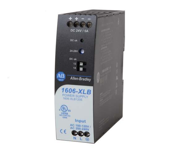
6 Front Side and User Elements Figure 1 - Front Side of DC-UPS Letter A B Description Input terminals - (screw terminals) N, L - Line input PE - Protective earth input Output terminals - (screw terminals, two pins per pole) + Positive output Negative (return) output C Output voltage potentiometer - Guaranteed adjustment range: 24 28V Factory set: 24.1V D DC-OK status indicator- (green) On, when the output voltage is >18V E DC-OK Relay Contact (push-in terminals) Protection Features Attribute Output protection Output overvoltage protection 1606-XLB120E Electronically protected against overload, no-load, and short circuits typ 31V DC max 34V DC In case of an internal power supply anomaly, a redundant circuit limits the maximum output voltage. In such a case, the output shuts down and stays down until the input voltage is turned off and on again for at least 1 minute or until the green status indicator went off. Degree of protection IP 20 EN/IEC Caution: For use in a controlled environment according to CSA 22.2 No Over-temperature protection Input transient protection no MOV (Metal Oxide Varistor) Internal input fuse Included Not user replaceable 6 Rockwell Automation Publication 1606-RM055B-EN-P - February 2017
7 Safety Features Attribute Input/output separation double or reinforced insulation 1606-XLB120E SELV IEC/EN PELV IEC/EN , EN 50178, IEC 62103, IEC Class of protection I PE (Protective Earth) connection required Isolation resistance > 100 MOhm Input to output, 500V DC Touch current (leakage current) typ 0.21 ma/0.46 ma typ 0.30 ma/0.65 ma typ 0.33 ma/0.72 ma 100V AC, 50 Hz, TN-,TT-mains/IT-mains 120V AC, 60 Hz, TN-,TT-mains/IT-mains 230V AC, 50 Hz, TN-,TT-mains/IT-mains < 0.27 ma/0.56 ma 110V AC, 50 Hz, TN-,TT-mains/IT-mains < 0.38 ma/0.78 ma 132V AC, 60 Hz, TN-,TT-mains/IT-mains < 0.43 ma/0.90 ma 264V AC, 50 Hz, TN-,TT-mains/IT-mains Installation Notes Use appropriate copper cables that are designed for minimum operating temperatures of: 75 C (167 F) for ambient up to 55 C (131 F) minimum. 90 C (194 F) for ambient up to 70 C (158 F) minimum. Follow national installation codes and installation regulations Verify that all strands of a stranded wire enter the terminal connection. Do not use the power supply without a PE connection. Secure unused terminal compartments tightly. Ferrules are allowed. Terminals and Wiring The terminals are IP20 Fingersafe constructed and suitable for field- and factory wiring. Attribute Input and Output Terminals DC-OK Signal Terminal Terminal type Screw terminals Push-in terminals Solid wire, max 6 mm mm 2 Stranded wire, max 4 mm mm 2 American Wire Gauge AWG AWG Wire diameter, max including ferrules) 2.8 mm (0.11 in.) 1.6 mm (0.06 in.) Wire stripping length 7 mm (0.28 in.) 7 mm (0.28 in.) Screwdriver 3.5 mm (0.14 in.) slotted or cross-head No 2 Not required Recommended tightening torque 1 N m (9 lb in) Not applicable Rockwell Automation Publication 1606-RM055B-EN-P - February
8 Input Attribute 1606-XLB120E AC input nom V/ V AC Auto-select, suitable for TN-, TT- and IT mains networks AC input range min V AC/ V AC continuous operation min V AC < 500 ms Allowed voltage L or N to earth max 300V AC continuous, IEC Input frequency nom Hz ±6% External input protection See recommendations in External Input Protection on page 16 Attribute AC 100V AC 120V AC 230V Input current typ 2.0 A 1.72 A 1.05 A at 24V, 5 A, see Figure 3 Power factor (1) typ at 24V, 5 A, see Figure 5 Crest factor (2) typ at 24V, 5 A Turn-on voltage typ 78V AC 78V AC 157V AC at 24V 0 A, steady-state value, see Figure 2 Shut-down voltage typ 68V AC 68V AC 68V AC at 24V 5 A, steady-state value, see Figure 2 Start-up delay typ 400 ms 400 ms 100 ms see Figure 4 Rise time typ 30 ms 30 ms 30 ms at 24V, 5 A const. current load, 0mF load capacitance, see Figure 4 typ 90 ms 90 ms 90 ms at 24V, 5 A const. current load, 5mF load capacitance, see Figure 4 Turn-on overshoot max 200 mv 200 mv 200 mv see Figure 4 (1) The power factor is the ratio of the true (or real) power to the apparent power in an AC circuit. (2) The crest factor is the mathematical ratio of the peak value to the T ms value of the input current waveform. Figure 2 - Input Voltage Range, typ Figure 4 - Turn-on Behavior, Definitions P OUT Rated input ranges max. 500ms Input Voltage Shut-down Turn-on 90 Lower range Upper range V IN Vac Output Voltage - 5% Start-up delay Rise Time Overshoot Figure 3 - Input Current vs. Output Load at 24V Figure 5 - Power Factor vs. Output Load Input Current, typ. 2.2A a) 100Vac b) 120Vac c) 230Vac 0.3 Output Current A a b c Power Factor, typ a) 100Vac 0.65 b) 120Vac a c) 230Vac b Output Current A c 8 Rockwell Automation Publication 1606-RM055B-EN-P - February 2017
9 DC-Input Do not operate the power supply with DC-input voltage. Input Inrush Current A NTC inrush limiter limits the input inrush current after turn-on of the input voltage. Attribute AC 100V AC 120V AC 230V Notes Inrush max 23 A peak 27 A peak 40 A peak 40 C (104 F) ambient, cold start current typ 18 A peak 22 A peak 33 A peak Inrush typ 13 A peak 16 A peak 30 A peak 25 C (77 F) ambient, cold start energy max 0.4 A 2 s 0.5 A 2 s 1.5 A 2 s 40 C (104 F) ambient, cold start Figure 6 - Input Inrush Current, Typical Behavior, 230V AC Input, 24V 5 A Output, 40 C (104 F) Ambient Figure 7 - Input Inrush Current, Zoom Into First Peak 230V AC Input, 24V 5 A Output, 40 C (104 F) Ambient 20ms/DIV 1ms/DIV Input current 20A/DIV Ipeak = 33A Input voltage 500V/DIV Input current 10A/DIV Output voltage 20V/DIV Rockwell Automation Publication 1606-RM055B-EN-P - February
10 Output Attribute 1606-XLB120E Notes Output voltage nom DC 24V Adjustment range min 24 28V guaranteed max 30V (1) at clockwise end position of potentiometer Factory settings typ 24.1V ±0.2 %, at full load, cold unit Line regulation max 10 mv / V AC Load regulation max 150 mv static value, 0 A.. 5 A.. 0 A Ripple and noise voltage max 100 mvpp 20 Hz to 20 MHz, 50 Ohms Output current for AC / V mains voltages (includes AC 208V mains): nom 5 A at 24V, below 55 C (122 F) ambient temperature 4.3 A at 28V, below 55 C (122 F) ambient temperature 3.1 A at 24V, at 70 C (158 F) ambient temperature 2.7 A at 28V, at 70 C (158 F) ambient temperature Derate linearly between +55 C (122 F) and +70 C (158 F) for AC 100/200V mains voltages: nom 5 A at 24V, below 55 C (122 F) ambient temperature 4.3 A at 28V, below 55 C (122 F) ambient temperature 2.5 A at 24V, at 70 C (158 F) ambient temperature 2.1 A at 28V, at 70 C (158 F) ambient temperature Derate linearly C ( F) Overload behavior continuous current output voltage > 10V DC, see Figure 8 Intermittent output voltage < 10V DC, see Figure 8 Short Circuit current typ 3.5 A (2) average (R.M.S.) current, load impedance 50mOhm Output capacitance typ μf included inside the power supply (1) This is the maximum output voltage that can occur at the clockwise end position of the potentiometer due to tolerances. It is not guaranteed value that can be achieved. The typical value is about 28.5V. (2) Discharge current of output capacitors is not included. Figure 8 - Output Voltage vs. Output Current, R ms current, typ Figure 9 - Intermittent Operation at Shorted Output, typ Output Voltage 28V continuous current intermittent operation Adjustment Range A A / 264Vac B / 187Vac B A 1 Output Current 60ms 360ms 9.2A 10 Rockwell Automation Publication 1606-RM055B-EN-P - February 2017
11 Hold-up Time Type AC 100V AC 120V AC 230V 24V, 2.5 A typ 64 ms 108 ms 105 ms min 54 ms 91 ms 88 ms 24V, 5 A typ 26 ms 51 ms 50 ms min 22 ms 43 ms 42 ms Figure 10 - Hold-up Time vs. Input Voltage Figure 11 - Shut-down behavior, definitions Hold-up Time a) 24V 2.5A typ. b) 24V 2.5A min. a b c d 125ms c) 24V 5A typ. a d) 24V 5A min. b c d Vac Input Voltage Output Voltage Zero Transition Hold-up Time - 5% Input Voltage DC OK Relay Contact This feature monitors the output voltage that is produced by the power supply itself. It is independent of a back-fed voltage from a unit that is connected in parallel to the power supply output (for example, redundant application). Attribute 1606-XLB120E Contact closes As soon as the output voltage reaches 21.4V Contact opens As soon as the output voltage dips below 21.4V Contact ratings max 60V DC 0.3 A, 30V DC 1 A, 30V AC 0.5 A resistive load min 1 ma at 5V DC minimum required load Isolation voltage See Dielectric Strength on page 21 Figure 12 - DC-OK Relay Contact Behavior Output Voltage 21.4V open closed Rockwell Automation Publication 1606-RM055B-EN-P - February
12 Efficiency and Power Loss Attribute AC 100V AC 120V AC 230V Notes Efficiency typ 90.7% 91.2% 92.3% at 24V, 5 A Average typ 89.2% 89.4% 90.6% 25% at 1.25 A, 25% at 2.5 A, efficiency (1) 25% at 3.75 A. 25% at 5 A Power losses typ 1.4 W 1.5 W 0.7 W at 24V, 0 A typ 7.0 W 7.4 W 6.0 W at 24V, 2.5 A typ 12.3 W 11.6 W 10.0 W at 24V, 5 A (1) The average efficiency is an assumption for a typical application where the power supply is loaded with 25% of the nominal load for 25% of the time, 50% of the nominal load for another 25% of the time, 75% of the nominal load for another 25% of the time and with 100% of the nominal load for the rest of the time. Figure 13 - Efficiency vs. Output Current, typ Figure 15 - Power Losses vs. Output Current at 24V, typ Efficiency 93% c 92 b 91 a a) 100Vac b) 120Vac c) 230Vac Output Current A Power Losses 12W a b 10 c 8 6 a) 100Vac 4 b) 120Vac c) 230Vac 2 0 Output Current A Figure 14 - Efficiency vs. Input Voltage at 24V, 5 A, typ Figure 16 - Power Losses vs. Input Voltage at 24V, 5 A Efficiency 93% Input Voltage Vac Power Losses 14W Input Voltage Vac 12 Rockwell Automation Publication 1606-RM055B-EN-P - February 2017
13 Lifetime Expectancy and Mean Time between Failure (MTBF) Attribute AC 100V AC 120V AC 230V Notes Lifetime h h h at 24V, expectancy (1) 2.5 A and 40 C (104 F) h h h at 24V, 2.5 A and 25 C (77 F) h h h at 24V, 5 A and 40 C (104 F) h h h at 24V, 5 A and 25 C (77 F) MTBF (2) SN 29500, IEC MIL HDBK 217 F h h h at 24V, 5 A and 40 C (104 F) h h h at 24V, 5 A and 25 C (77 F) h h h at 24V, 5 A and 40 C (104 F); Ground Benign GB h h h at 24V, 5 A and 25 C (77 F); Ground Benign GB h h h at 24V, 5 A and 40 C(104 F); Ground Fixed GF h h h at 24V, 5 A and 25 C (77 F); Ground Fixed GF25 (1) The Lifetime expectancy that is shown in the table indicates the minimum operating hours (service life) and is determined by the lifetime expectancy of the built-in electrolytic capacitors. Lifetime expectancy is specified in operational hours and is calculated according to the capacitor s manufacturer specification. The manufacturer of the electrolytic capacitors only guarantees a maximum life of up to 15 years ( h). Any number exceeding this value is a calculated theoretical lifetime which can be used to compare devices. (2) MTBF stands for Mean Time Between Failure, which is calculated according to statistical device failures, and indicates reliability of a device. It is the statistical representation of the likelihood of a unit to fail and does not necessarily represent the life of a product. The MTBF figure is a statistical representation of the likelihood of a device to fail. A MTBF figure of for example, h means that statistically one unit fails every 100 hours if units are installed in the field. However, it cannot be determined if the failed unit has been running for h or only for 100 h. Functional Diagram Figure 17 - Functional Diagram Output Voltage Regulator V OUT L N Input Fuse & Input Filter Input Rectifier & Inrush Limiter (NTC) Power Converter Output Filter /230V Auto Select Output Over- Voltage Protection DC-ok Relay DC ok DC-ok Contact Rockwell Automation Publication 1606-RM055B-EN-P - February
14 EMC EMC Immunity According to Generic Standards EN and EN Criterion (1) Electrostatic discharge EN contact discharge air discharge 8 kv 8 kv Electromagnetic RF field EN MHz-2.7 GHz 20V/m Fast transients (Burst) EN input lines output lines DC-OK signal (coupling clamp) Surge voltage on input EN L ->N L ->PE, N ->PE Surge voltage on output EN >- +/- ->PE 4 kv 2 kv 2 kv 2 kv 4 kv 500V 1 kv Surge voltage on DC-OK EN DC-OK signal PE 1 kv Conducted disturbance EN M Hz 20V Mains voltage dips EN % of 100V AC 40% of 100V AC 70% of 100V AC 0% of 200V AC 40% of 200V AC 70% of 200V AC 0V AC, 20 ms 40V AC, 200 ms 70V AC, 500 ms 0V AC, 20 ms 80V AC, 200 ms 140V AC, 500 ms Criterion C (2) Criterion C Voltage interruptions EN % of 220V AC (=0V) 5000 ms Criterion C Voltage sags SEMI F dips on the input voltage according to SEMI F47 standard 80% of 208V AC (166V AC) 70% of 208V AC (146V AC) 50% of 208V AC (104V AC) 80% of 120V AC (96V AC) 70% of 120V AC (84V AC) 50% of 120V AC (60V AC) 1000 ms 500 ms 200 ms 1000 ms 500 ms 200 ms Criterion C Criterion C Powerful transients VDE 0160 over entire load range 750V, 1.3 ms (1) : Power supply shows normal operation behavior withing the defined limits. Criterion C: Temporary loss of function is possible. Power supply can shut down and restart by itself. No damage or hazard for the power supply occurs. (2) Below 4.5 A, Criterion C for currents above 5 A. EMC Emission According to Generic Standards: EN , EN Conducted emission input lines EN 55011, EN FCC Part 15 CISPR 11, CISPR 22 Class B Conducted emission output IEC/CISPR , IEC/CISPR limits for DC power port according to EN lines (1) not fulfilled Radiated emission EN 55011, EN Class B Harmonic input current EN Fulfilled for class A equipment Voltage fluctuations, flicker EN Fulfilled (2) This device complies with FCC Part 15 rules. Operation is subjected to following two conditions: (1) this device cannot cause harmful interference, and (2) this device must accept any interference received, including interference that can cause undesired operation. (1) For information only, not mandatory for EN (2) Tested with constant current loads, non-pulsing. 14 Rockwell Automation Publication 1606-RM055B-EN-P - February 2017
15 Application Notes Peak Current Capability The unit can deliver peak currents (up to several milliseconds) which are higher than the specified short-term currents. This helps to start current demanding loads. Solenoids, contactors, and pneumatic modules often have a steady state coil and a pick-up coil. The inrush current demand of the pick-up coil is several times higher than the steady-state current and usually exceeds the nominal output current. The same situation applies when starting a capacitive load. The peak current capability also verifies the safe operation of subsequent circuit breakers of load circuits. The load branches are often individually protected with circuit breakers or fuses. If there is a short or an overload in one branch circuit, the fuse or circuit breaker need a certain amount of overcurrent to open in a timely manner. This avoids voltage loss in adjacent circuits. The extra current (peak current) is supplied by the power converter and the built-in large sized output capacitors of the power supply. The capacitors get discharged during such an event, which causes a voltage dip on the output. The following two examples show typical voltage dips: Figure 18 - Peak Load with 2x the Nominal Current for 50 ms, typ Figure 19 - Peak Load with 5x the Nominal Current for 5 ms, typ 24V Output Voltage 24V Output Voltage 17V 10A 25A 9V 0A Output Current 0A Output Current 10ms/DIV 1ms/DIV 10 A Peak load (resistive) for 50 ms Output voltage dips from 24V to 17V. 25 A Peak load (resistive) for 5 ms Output voltage dips from 24V to 9V. Peak Current Capability Voltage Dip Peak Load Peak current voltage dips typ 24 17V at 10 A for 50 ms, resistive load typ 24 13V at 25 A for 2 ms, resistive load typ 24 9V at 25 A for 5 ms, resistive load Back Feeding Loads Loads such as decelerating motors and inductors can feed voltage back to the power supply. This feature is also called return voltage immunity or resistance against Back- E.M.F. (Electro Magnetic Force). Rockwell Automation Publication 1606-RM055B-EN-P - February
16 This power supply is resistant and does not show malfunctioning when a load feeds back voltage to the power supply. It does not matter whether the power supply is on or off. The maximum allowed feed-back-voltage is 35V DC. The absorbing energy can be calculated according to the built-in large sized output capacitor that is specified in Output on page 10. External Input Protection The unit is tested and approved for branch circuits up to 30 A (UL) and 32 A (IEC). An external protection is only required if the supplying branch has an ampacity greater than this. Check also local codes and local requirements. In some countries local regulations might apply. If an external fuse is necessary or utilized, minimum requirements need to be considered to avoid nuisance tripping of the circuit breaker. A minimum value of 10 A, B-characteristic or 6 A, C-characteristic breaker should be used. Parallel Use to Increase Output Power Do not use the power supply in parallel to increase the output power. Parallel Use for Redundancy Power supplies can be paralleled for redundancy to gain higher system availability. Redundant systems require a certain amount of extra power to support the load in case one power supply unit fails. The simplest way is to put two power supplies in parallel. This is called a 1+1 redundancy. In case one power supply unit fails, the other one is automatically able to support the load current without any interruption. This simple way to build a redundant system does not cover failures such as an internal short circuit in the secondary side of the power supply. In such a case, the defect unit becomes a load for the other power supplies and the output voltage cannot be maintained any more. This can only be avoided by utilizing decoupling diodes that are included in the redundancy module. Recommendations for building redundant power systems: Use the DC-OK signal contact to monitor the individual power supply units. Use separate input fuses for each power supply. Use separate mains systems for each power supply whenever it is possible. It is desirable to set the output voltages of all units to the same value (± 100 mv) or leave it at the factory setting. 16 Rockwell Automation Publication 1606-RM055B-EN-P - February 2017
17 Series Operation Power supplies of the same type can be connected in series for higher output voltages. It is possible to connect as many units in series as needed, providing the sum of the output voltage does not exceed 150V DC. Voltages with a potential above 60V DC are not SELV any more and can be dangerous. Such voltages must be installed with a protection against touching. Earthing of the output is required when the sum of the output voltage is above 60V DC. Avoid return voltage (for example, from a decelerating motor or battery) which is applied to the output terminals. Keep an installation clearance (left/right) of 15 mm (0.59 in.)between two power supplies and avoid installing the power supplies on top of each other. Pay attention that leakage current, EMI, inrush current, harmonics increase when using multiple power supplies. Figure 20 - Series Operation Unit A AC DC Unit B AC DC Load - Earth (see notes) Inductive and Capacitive Loads No limitations for inductive loads. No limitations for capacitive loads in combination with an additional resistive type of load. Limitations apply for capacitive loads in combination with constant current type of loads: 20 mf Max with an additional 2.5 A constant current load and 10 mf max with an additional 5 A constant current load. Charging of Batteries Do not use the power supply to charge batteries. Rockwell Automation Publication 1606-RM055B-EN-P - February
18 Operation on Two Phases The power supply can also be used on two-phases of a three-phase-system. Such a phase-to-phase connection is allowed as long as the supplying voltage is below 240V +10%. Figure 21 - Operation on Two Phases L3 L1 L2 240V +10% max. Fuse Power Supply AC internal fuse L N PE DC Use in a Tightly Sealed Enclosure When the power supply is installed in a tightly sealed enclosure, the temperature inside the enclosure is higher than outside. In such situations, the inside temperature defines the ambient temperature for the power supply. The following measurement results can be used as a reference to estimate the temperature rise inside the enclosure. The power supply is placed in the middle of the box; no other heat producing items are inside the box. Enclosure Rittal Type IP 66 Box PK Plastic 110 x 180 x 165 mm (4.33 x 7.09 x 6.50 in) Input 230V AC Attribute Case A Case B Load (1) 24V, 5 A 24V, 4 A (=80 %) Temperature inside the box (2) 41.5 C (106.7 F) 38.9 C (102 F) Temperature outside the box 24.4 C (75.9 F) 24.2 C (75.6 F) Temperature rise 17.1K 14.5K (1) Load is placed outside the box. (2) In the middle of the right side of the power supply with a distance of 1 cm (0.39 in.). 18 Rockwell Automation Publication 1606-RM055B-EN-P - February 2017
19 Specifications Attribute 1606-XLB120E Notes Output voltage DC 24V Output for AC / V mains: for AC 100/200V mains: 24 28V DC A A A A Adjustment range at 24 28V, <55 C (122 F) at 24 28V, <70 C (158 F) at 24 28V, <50 C (122 F) at 24 28V, <70 C (158 F) Output ripple < 100 mvpp 20 Hz to 20 MHz AC Input voltage AC V/ V Mains frequency Hz ±6 % ±10% Auto-Select AC Input current 1.72 A/1.05 A at 120/ 230V AC Power factor 0.64/0.54 at 120/ 230V AC AC Inrush current 22 A/33 A peak at 120/ 230V AC, 40 C (140 F) Efficiency 91.2 /92.3% at 120/ 230V AC Losses 11.6 W/10.0 W at 120/ 230V AC Temp. range C ( F) operational Derating 3 W/ C C ( F) (1) Hold-up time 51 ms/50 ms at 120/ 230V AC Dimensions 39 x 124 x124 mm W x H x D (1.53 x 4.88 x 4.88) Weight 370 g/0.81 lb (1) C ( F) for AC 100 V/ 200V mains Rockwell Automation Publication 1606-RM055B-EN-P - February
20 Environment Attribute 1606-XLB120E Notes Operational temperature (1) C ( F) reduce output power according to Figure 22 Storage temperature C ( F) for storage and transportation Output derating (2) 3W/ C (55 70 C F) 3W/ C (50 70 C; F) for AC / V mains systems for AC 100/200V mains systems Humidity (3) % r.h. IEC Vibration sinusoidal (4) Hz: ±1.6mm; Hz: 2g IEC hours/axis Shock (5) 30g 6ms, 20g 11ms 3 bumps/direction, 18 bumps in total IEC Altitude m ( ft.) without any restrictions m ( ft.) reduce output power or ambient temperature, see Figure 22 IEC 62103, EN 50178, overvoltage category II Altitude derating 7.5W/1000m or 5 C/1000m > 2000 m (6500 ft.), see Figure 23 Overvoltage category III IEC 62103, EN 50178, altitudes up to 2000m II altitudes from 2000m to 6000m Degree of pollution 2 IEC 62103, EN 50178, not conductive LABS compatibility The unit does not release any silicone or other LABS-critical substances and is suitable for use in paint shops. (1) Operational temperature is the same as the ambient or surrounding temperature and is defined as the air temperature 2cm below the unit. (2) For AC 208V mains use AC V values. (3) Do not energize while condensation is present. (4) Tested on a DIN Rail with a thickness of 1.3 mm. (5) Tested on a DIN Rail with a thickness of 1.3 mm. Figure 22 - Output Current vs. Ambient Temperature Figure 23 - Output Current vs. Altitude Allowable Output Current at 24V 5.0A 4.0A 3.1A 2.5A 2.0A a) AC / V mains b) AC 100/ 200V mains 1.0A Ambient Temperature C a b Allowed Output Current at 24V 6A A... Tamb < 55 C B... Tamb < 45 C C... Tamb < 35 C C B A 1 Altitude m 20 Rockwell Automation Publication 1606-RM055B-EN-P - February 2017
21 Dielectric Strength The output voltage is floating and has no ohmic connection to the ground. Type and factory tests are conducted by the manufacturer. Field tests can be conducted in the field using the appropriate test equipment, which applies the voltage with a slow ramp (2 s up and 2 s down). Connect all input-terminals together and all output poles before conducting the test. When testing, set the cutoff current settings to the value in the following table. A B C D Type test 60 s 2500V AC 3000V AC 1000V AC 500V AC Factory test 5 s 2500V AC 2500V AC 500V AC 500V AC Field test 5 s 2000V AC 2000V AC 500V AC 500V AC Cutoff current setting > 10 ma > 10 ma > 15 ma > 1 ma Figure 24 - Dielectric Strength Input L N B *) DC-ok A B D Earth, PE C Output + - B*) When testing input to DC-OK ensure that the max. voltage between DC-OK and the output is not exceeded (column D). We recommend connecting DC-OK pins and the output pins together when performing the test. To meet the PELV requirements according to EN , we recommend that either the + pole, the pole or any other part of the output circuit be connected to the protective earth system. This helps to avoid situations in which a load starts unexpectedly or cannot be switched off when unnoticed earth faults occur. Rockwell Automation Publication 1606-RM055B-EN-P - February
22 Standards Compliance and Certifications EC Declaration of Conformity The CE Marking indicates conformance with the low voltage directive and EMC Directive. EN , EN UL 508 Listed for use as Industrial Control Equipment ;U.S.A. (UL 508) and Canada (C22.2 No ); File: E56639 UL Recognized for use as Information Technology Equipment, U.S.A. (UL ) and Canada (C22.2 No ); File: E RCM Declaration of Conformity C-tick is for products intended for sale and use within the Australian market. EAC EAC is for products intended for sale and use within the Russian market. 22 Rockwell Automation Publication 1606-RM055B-EN-P - February 2017
23 Approximate Dimensions and Weight Attribute Width Height Depth (1) 1606-XLB120E 39 mm (1.54 in.) 125 mm (4.92 in.) mm (5.08 in.) Weight DIN Rail Plastic Material of Housing 370 g (0.81 lb) Use 35 mm DIN rails according to EN or EN with a height of 7.5 or 15 mm. Flame retardant Polycarbonate (PC) - UL94-V0 Vicat softening temperature specified with 149 C according to ASTM D1525 Installation Clearances Keep the following installation clearances: 40 mm on top, 20 mm on the bottom, 5 mm on the left and right sides are recommended when the device is loaded permanently with more than 50% of the rated power. Increase this clearance to 15 mm in case the adjacent device is a heat source (for example, another power supply). (1) The DIN rail height must be added to the unit depth to calculate the total required installation depth. Dimensions are in mm (in). Figure 25 - Front View 39 (1.54) 125 (4.92) Figure 26 - Side View (5.08) Rockwell Automation Publication 1606-RM055B-EN-P - February
24 Notes: 24 Rockwell Automation Publication 1606-RM055B-EN-P - February 2017
25
26 . Rockwell Automation Support Use the following resources to access support information. Technical Support Center Knowledgebase Articles, How-to Videos, FAQs, Chat, User Forums, and Product Notification Updates. Local Technical Support Phone Numbers Locate the phone number for your country. Direct Dial Codes Literature Library Product Compatibility and Download Center (PCDC) Find the Direct Dial Code for your product. Use the code to route your call directly to a technical support engineer. Installation Instructions, Manuals, Brochures, and Technical Data. Get help determining how products interact, check features and capabilities, and find associated firmware Documentation Feedback Your comments will help us serve your documentation needs better. If you have any suggestions on how to improve this document, complete the How Are We Doing? form at Rockwell Automation maintains current product environmental information on its website at Allen-Bradley, Rockwell Automation, and Rockwell Software are trademarks of Rockwell Automation, Inc. Trademarks not belonging to Rockwell Automation are property of their respective companies. Rockwell Otomasyon Ticaret A.Ş., Kar Plaza İş Merkezi E Blok Kat: İçerenköy, İstanbul, Tel: +90 (216) Publication 1606-RM055B-EN-P February 2017 Supersedes Publication 1606-RM055A-EN-P December 2016 Copyright 2017 Rockwell Automation, Inc. All rights reserved. Printed in the U.S.A.
P R E L I M I N A R Y SHORT-FORM DATA MARKINGS
 P R E L I M I N A R Y POWER SUPPLY AC 100-120V / 200-240V Auto-Select Input Cost Optimized without Compromising Quality or Reliability. Width only 39mm Efficiency up to 92.6% Full Power Between -10 C and
POWER SUPPLY SHORT-FORM DATA MARKINGS
 POWER SUPPLY 2MOPP Safety Approved for Medical applications According to IEC 661-1, 3 rd edition EMC Tested for Medical Use According to IEC 661-1-2, 4 th edition Quick-connect Spring-clamp Terminals AC
Starting Torque Controller Technical Data
 Technical Data Starting Torque Controller Technical Data Bulletin 154 Topic Page Product Overview 2 Catalog Number Explanation 2 Product Selection 3 Specifications 3 Wiring Diagrams 9 Approximate Dimensions
CP10.241, CP10.242, CP S1
 POWER SUPPLY AC 1-24V Wide-range Input Width only 39mm Optional with Spring-clamp Terminals (CP1.241-S1) Optional with Extended DC Input Range (CP1.242) Efficiency up to 95.2%, Excellent Partial Load Efficiency
SHORT-FORM DATA MARKINGS
 POWER SUPPLY AC 1-24V Wide-range Input Width only 39mm +1% (5.4A) continuous current up to +6 C +2% (6A) continuous current up to +45 C Efficiency up to 95.5%, Excellent Partial Load Efficiency Safe Hiccup
Bulletin 1606 Switched Mode Power Supplies
 Reference Manual Bulletin 166 Switched Mode Supplies Catalog Number: 166-XLS96EE Index Page 1. Intended Use...3 2. Installation Requirements...3 3. AC-Input...4 4. Input Inrush Current...5 5. DC-Input...5
Bulletin 1606 Switched Mode Power Supplies
 Reference Manual Bulletin 166 Switched Mode Supplies Catalog Number: 166-XLS96E-3 Index Page 1. Intended Use...3 2. Installation Requirements...3 3. AC-Input...4 4. Input Inrush Current...5 5. DC-Input...5
SHORT-FORM DATA MARKINGS
 POWER SUPPLY AC 2-24V Input Width only 125mm, Weight only 1.8kg 95.% Full Load and Excellent Partial Load Efficiencies 5% Bonus, 144W for up to 4s 55A High Peak Current for 25ms for Easy Fuse Tripping
SHORT-FORM DATA MARKINGS
 POWER SUPPLY AC 1-24V Wide-range Input Width only 125mm, Weight only 1.9kg 94.6% Full Load and Excellent Partial Load Efficiencies 5% Bonus, 144W for up to 4s 7A High Peak Current for 1ms for Easy Fuse
CP R1, CP R2, CP R3, CP R2, CP R2-C1
 P R E L I M I N A R Y REDUNDANCY POWER SUPPLY AC 100-240V Wide-range Input Width only 48mm Built-in Decoupling Mosfet for 1+1 and n+1 Redundancy Efficiency up to 95.2% 20% Power Reserves Safe Hiccup PLUS
QS20.241, QS A1, QS C1
 POWER SUPPLY AC 100-240V Wide-range Input Width only 82mm Efficiency up to 93.9% ATEX and IECEx Approved (-A1 Version) -C1 Version with Conformal Coated PC-board 150% (720W) Peak Load Capability Safe Hiccup
Power supply CP-E 24/2.5
 2CDC 271 015 F0t06 a OUTPUT L+, L : terminals output b DC OK: terminal signalling output c INPUT L, N, PE: terminals input d OUTPUT OK: green LED output voltage OK e OUTPUT Adjust: potentiometer adjustment
SHORT-FORM DATA MARKINGS
 POWER SUPPLY AC 2-24V Input Width only 125mm, Weight only 1.8kg 94.6% Full Load and Excellent Partial Load Efficiencies 5% Bonus, 144W for up to 4s 11A High Peak Current for 25ms for Easy Fuse Tripping
MINI-PS AC/24DC/1.3
 Power supply unit INTERFACE Data sheet 102894_en_03 1 Description PHOENIX CONTACT 2015-11-17 Features MINI POWER power supplies for MCR technology In measurement and control technology (MCR), modular electronics
SHORT-FORM DATA MARKINGS
 POWER SUPPLY 3AC 38-48V Wide-range Input Also Specified for 2-Phase Operation 94.8% Full Load and Excellent Partial Load Efficiencies Width only 65mm, Weight only 87g 5% Bonus, 72W for up to 4s Active
Bulletin 1606 Switched Mode Power Supplies
 Reference Manual Bulletin 166 Switched Mode Supplies Catalog Number: 166-XLS96F-3 Index Page 1. Intended Use...3 2. Installation Requirements...3 3. AC-Input...4 4. Input Inrush Current...5 5. DC-Input...5
Power supply CP-E 24/20.0
 2CDC 271 027 F0008 a OUTPUT L+, L+, L, L-: terminals output b INPUT L, N, PE: terminals input c 13-14: terminals - signalling contact d OUTPUT OK: green LED output voltage OK e OUTPUT LOW: red LED output
QUINT-PS/ 3AC/24DC/10
 Primary-switched power supply with SFB technology, 3 AC, output current 10 A INTERFACE Data sheet 103131_en_01 1 Description PHOENIX CONTACT - 09/2009 Features QUINT POWER power supply units Maximum system
Power supply CP-T 24/20.0 Primary switch mode power supply
 Data sheet Power supply CP-T 24/20.0 Primary switch mode power supply The CP-T range of three-phase power supply units is the youngest member of ABB s power supply family. In terms of design and functionality,
Power supply CP-T 48/20.0 Primary switch mode power supply
 Data sheet Power supply CP-T 48/20.0 Primary switch mode power supply The CP-T range of three-phase power supply units is the youngest member of ABB s power supply family. In terms of design and functionality,
SHORT-FORM DATA MARKINGS. IECEx
 MOSFET REDUNDANCY MODULE Single with Single Equipped with Plug-connector for Hot Swapping Suitable for all DIMENSION Power Supplies Except QT40 Series Only 150mV Voltage Drop at 40A Only 6.2W at 40A 160%
Notes: Note1: Efficiency is tested at nominal input and full load at +25 C ambient. Output Voltage 400VAC 320VAC 360VAC 400VAC 400VAC
 Features DIN-Rail 2 and 3-phase operation Input voltage range: 320 575VAC Output trim range: 22.5 29.5VDC High electrical strength; high reliability Permanent overload and short-circuit protection Parallel
QUINT-PS AC/24DC/40
 Power supply unit INTERFACE Data sheet 102315_en_02 1 Description PHOENIX CONTACT 2010-04-23 Features QUINT POWER power supply units for plant and special engineering reliably start heavy loads with high
Notes: Note1: Efficiency is tested at nominal input and full load at +25 C ambient. Output Voltage 400VAC 400VAC
 Features DIN-Rail Description 2 and 3-phase operation Input voltage range: 320 575VAC Output trim range: 22.5 29.5VDC High electrical strength; high reliability Permanent overload and short-circuit protection
Type CP-S, CP-C & CP-A Switch mode
 Switch mode power CP-S, CP-C & CP-A Switch mode Characteristics CP-S and CP-C range Output current 5 A, 10 A and 20 A Integrated power reserve of up to 50 % 5 A and 10 A devices with pluggable connecting
Power supply CP-D 24/4.2 Primary switch mode power supply
 Data sheet Power supply CP-D 24/4.2 Primary switch mode power supply The CP-D range of modular power supply units in MDRC design (modular DIN rail components) is ideally suited for installation in distribution
Power supply CP-T 48/5.0 Primary switch mode power supply
 Data sheet Power supply CP-T 48/5.0 Primary switch mode power supply The CP-T range of three-phase power supply units is the youngest member of ABB s power supply family. In terms of design and functionality,
Power supply CP-T 24/10.0 Primary switch mode power supply
 Data sheet Power supply CP-T 24/10.0 Primary switch mode power supply The CP-T range of three-phase power supply units is the youngest member of ABB s power supply family. In terms of design and functionality,
SHORT-FORM DATA MARKINGS
 POWER SUPPLY AC 2-24V Width only 7mm Efficiency up to 94.5% Very Low No-load Losses 15% (72W) Peak Load Capability Easy Fuse Tripping due to High Overload Current Full Between -25 C and +6 C DC-OK Relay
Power supply CP-T 24/40.0 Primary switch mode power supply
 Data sheet Power supply CP-T 24/40.0 Primary switch mode power supply The CP-T range of three-phase power supply units is the youngest member of ABB s power supply family. In terms of design and functionality,
PHOENIX CONTACT - 06/2008. Features. DANGER OF EXPLOSION! Only remove equipment when it is disconnected and not in the potentially explosive area.
 Primary-switched power supply with SFB technology, 1 AC, output current 20 A INTERFACE Data Sheet 103383_en_00 1 Description PHOENIX CONTACT - 06/2008 Features QUINT POWER power supply units highest system
SHORT-FORM DATA MARKINGS
 POWER SUPPLY AC 100-240V Wide-range Input Width only 82mm Efficiency up to 94.0% 150% (720W) Peak Load Capability Easy Fuse Tripping due to High Overload Current Active Factor Correction (PFC) Negligible
QUINT-PS/ 3AC/24DC/40
 Primary-switched power supply unit with SFB technology, 3 AC, output current 40 A INTERFACE Data sheet 103133_en_00 1 Description PHOENIX CONTACT - 07/2009 Features QUINT POWER power supply units Maximum
Primary switch mode power supplies Product group picture
 Primary switch mode power supplies Product group picture /1 ABB Catalog Electronic Products and Relays 2015 2CDC 110 004 C0210 Primary switch mode power supplies Table of contents Primary switch mode power
Supplemental Motor Protection Devices Specifications
 Technical Data Supplemental Motor Protection Devices Specifications Bulletin Numbers 809S, 813S, 814S, 817S, 1409, 1410 Topic Bulletin 809S/813S/814S/817S 2 Page Product Line Overview 2 Cat. No. Explanation
Power supply CP-E 24/0.75
 2CDC 271 016 F0t06 a OUTPUT L+, L : terminals output b INPUT L, N, PE: terminals input c LOW: red LED output voltage too low d OK: green LED output voltage OK e OUTPUT Adjust: rotary potentiometer output
Supplemental Motor Protection Devices Specifications
 Technical Data Supplemental Motor Protection Devices Specifications Bulletin Numbers 809S, 813S, 814S, 817S, 1409, 1410 Topic Page 809S/813S/814S/817 Dedicated Function Motor Protection Relays 2 Product
Analog Laser Sensor. Installation Instructions. Specifications. Summary of Changes. Description. Catalog Numbers 45BPD-8LTB1-D5, 45BPD-8LTB2-D5
 Installation Instructions Original Instructions Analog Laser Sensor Catalog Numbers 45BPD-8LTB1-D5, 45BPD-8LTB2-D5 Topic IMPORTANT Summary of Changes This manual contains an update to the sensing beam
QS GENERAL DESCRIPTION 2. SHORT-FORM DATA 3. ORDER NUMBERS 4. MARKINGS POWER SUPPLY 24V, 20A, SINGLE PHASE INPUT 1/23.
 POWER SUPPLY AC 2-24V Input Efficiency up to 94.5% Width only 7mm 15% Peak Load Capability Full Between -25 C and 6 C DC-OK Relay Contact Quick-connect Spring-clamp Terminals 3 Year Warranty 1. GENERAL
QUINT-PS/ 1AC/24DC/20
 Primary-switched power supply with SFB technology, 1 AC, output current 20 A INTERFACE Data sheet 103129_en_04 1 Description PHOENIX CONTACT - 02/2010 Features QUINT POWER power supply units Maximum system
PHOENIX CONTACT - 05/2008. DANGER OF EXPLOSION! Remove an item only when it is not connected to power or if it is located in the non-explosive area.
 Primary-switched power supply with SFB technology, 1 AC, output current 20 A INTERFACE Data Sheet 103129_en_01 PHOENIX CONTACT - 05/2008 1 Description QUINT POWER power supply units highest system availability
Power supply CP-E 24/2.5
 2CDC 271 015 F0t06 a OUTPUT L+, L : terminals output b DC OK: terminal signalling output c INPUT L, N, PE: terminals input d OUTPUT OK: green LED output voltage OK e OUTPUT Adjust: potentiometer adjustment
NEMA Contactor and Starter Specifications
 Technical Data NEMA Contactor and Starter Specifications Bulletins 00, 0, 0, 0, 06, 06X, 07, 07X, 09,,, E/F/G, E/F/G Topic Page Specifications Electrical Ratings Mechanical Ratings, Construction, Environmental
Power supply CP-D 12/2.1
 2CDC 271 025 F0t07 a OUTPUT ++/ : terminals output Features Rated output voltage 12 V DC Output voltage adjustable via front face potentiometer OUTPUT Adjust Rated output current 2.1 A Rated output power
1715 Redundant I/O System Specifications
 Technical Data 1715 Redundant I/O System Specifications System Module Catalog Numbers 1715-AENTR, 1715-IB16D, 1715-OB8DE,1715-IF16, 1715-OF8I Base Unit Catalog Numbers 1715-A2A, 1715-A3IO Termination Assembly
CP-T range Product group picture
 Product group picture /1 ABB Catalog Electronic Products and Relays 1/1 2CDC 110 00 C09 Table of contents CP-T range Product group picture /1 Table of contents /2 Benefits and advantages / Ordering details
CP-E range Benefits and advantages
 Benefits and advantages Characteristics Output voltages 5 V, 12 V, 2 V, 8 V DC Adjustable output voltages Benefits Signalling output/contact Output currents 0.625 A / 0.75 A / 1.25 A / 2.5 A / A / 5 A
QUINT-PS-24DC/24DC/10
 QUINT-PS-24/24/10 QUINT - converter, primary switched mode, input: 24 V, output: 24 V /10 A INTERFACE Data Sheet PHOENIX CONTACT - 02/2006 Description The QUINT - converter 24 V/10 A converts the voltage
Features. Regulated Converter. RAC02-SE/277/W 2 Watt Single Output. RAC02- SE/277/W Wired. AC/DC Converter
 Features Regulated Converter Description 35mW max. no load power consumption Efficiency up to 76% Isolated output 3kVAC / 1 minute SCP, OVP protection Wide operating temperature range: -4 C to +85 C Universal
Switching power supplies CP range, Linear power supplies CP-L range. Content
 CP range, Linear power supplies CP-L range Content Switching power supplies, primary switch mode, CP range Benefits and advantages... 136 Approvals... 137 Ordering details... 138 Technical data... 11 Dimensional
Power supply CP-E 12/10.0 Primary switch mode power supply Data sheet
 2CDC 271 024 F0008 OUTPUT L+, L+, L-, L-: terminals - output INPUT L, N, PE: terminals - input OUTPUT OK: green LED - output voltage OK OUTPUT LOW: red LED - output voltage too low OUTPUT Adjust: potentiometer
Features. Regulated Converter. RAC02-SE/277 2 Watt Single Output RAC02- SE/277. AC/DC Converter
 Features Regulated Converter Description 5mW max. no load power consumption Efficiency up to 76% Isolated output kvac / min SCP, OVP protection Wide operating temperature range: -4 C to +85 C Universal
Power supply CP-D 24/1.3
 2CDC 271 027 F0t07 a OUTPUT ++/ : terminals output Features Rated output voltage 24 V DC Output voltage adjustable via front face potentiometer OUTPUT Adjust Rated output current 1.3 A Rated output power
MINI-PS AC/2X15DC/1
 MII-PS-100-240AC/2X15DC/1 Power supply unit ITERFACE Data sheet 100299_en_04 1 Description PHOEIX COTACT - 2010-10-20 Features MII POWER is the extremely slim power supply unit with constructional widths
Power supply CP-E 48/5.0 Primary switch mode power supply Data sheet
 2CDC 271 028 F0008 OUTPUT L+, L+, L-, L-: terminals - output Features Rated output voltage 48 V DC Output voltage adjustable via front-face rotary potentiometer OUTPUT Adjust Rated output current 5 A Rated
CB Scheme UL508 UL ATEX II3G
 Industrial Power Supplies UL Hazloc Class I, division 2 approval and ATEX certification SEMI F47 compliant for voltage sag immunity Rugged metal case with optional side-mounting Very high efficiency up
Measuring and monitoring relays CM-SRS.1 Current monitoring relays, single-phase AC/DC
 2CDC 251 244 F0t05 Characteristics Monitoring of DC and AC currents: RMS measuring principle One device includes 3 measuring ranges Over- or undercurrent monitoring configurable Hysteresis adjustable from
18V 35V 65V 40A 60A 1.5W 1.2W ms 40ms. 20ms 20ms
 Features DIN Rail Description Universal AC Input (85264VAC) Protections: SCP, OVP, OLP, OTP DC OK Indicator LED with Relay Contacts 5% (8W) peak load capacity Builtin active PFC,PF>,95 High effciency up
Features. Regulated Converters. RAC01-C RAC02-C 1-2 Watt Single Output RAC0_- C. AC/DC Converter
 Features Regulated Converters Description Compact low profile AC-DC power supply mw no load power consumption Class II power supply with kvac isolation Universal input voltage range (~VAC) Low output ripple/noise
Note1: Efficiency is tested at nominal input and full load at +25 C ambient Note2: Max Cap Load is tested at nominal input and full resisitive load
 Features Regulated Converter Description 4mW max. no load power consumption High efficiency up to 76% Isolated output 3kVAC / 1 min SCP, OVP protection Wide operating temperature range: -4 C to +85 C Universal
CP-T range Benefits and advantages
 Benefits and advantages Characteristics Rated output voltages V, V DC Output voltage adjustable via front-face rotary potentiometer OUTPUT Adjust Rated output currents 5 A, 10 A, A, A Rated output powers
Current monitoring relays CM-SRS.2 for single-phase AC/DC currents
 Data sheet Current monitoring relays CM-SRS.2 for single-phase AC/DC currents For the monitoring of currents in single-phase AC/DC systems, ABB s CM range comprises a wide selection of powerful and compact
DSA150 Series. xxx Series. 150 Watts. AC-DC Power Supplies. Models & Ratings. Mechanical Details 3.92 (99.8) 2.18 (55.5) 4.92 (125.
 2.18 (55.5) 4.92 (125.") 15 Watts xxx Series Ultra Slim Design 15% Peak Load for 3 seconds Ambient Operation from -1 C to +7 C High Efficiency Selectable Overload Characteristic Selectable Remote Inhibit or Enable 3 Year Warranty
15 Watts xxx Series Ultra Slim Design 15% Peak Load for 3 seconds Ambient Operation from -1 C to +7 C High Efficiency Selectable Overload Characteristic Selectable Remote Inhibit or Enable 3 Year Warranty
1606-XLS480E-3 24V, 20A Three Phase Input
 166-XLS48E-3 24V, 2A; Three Phase Input 166-XLS48E-3 24V, 2A Three Phase Input POWER SUPPLY Ultra-small size Extra-low inrush current Active power factor correction Wide range AC/DC input; auto select
ADC5000 SERIES. AC/DC Switch Mode Power Supplies and Rectifiers for Industrial and Telecom Applications. 60W, 125W and 250 W
 ADC5000 SERIES AC/DC Switch Mode Power Supplies and Rectifiers for Industrial and Telecom Applications 60W, 125W and 250 W Input voltage 230/115 VAC voltages 12, 24, 36 or 48 VDC Statistical MTBF >3 000
120/240 Watt AC-DC Front End with PFC W Series Convert Select 120 Convert Select 240
 Industrial Environment AC-DC Converters >100 Watt W Series 120/240 Watt AC-DC Front End with PFC W Series Convert Select 120 Convert Select 240 Rugged 35 mm DIN-rail snap-fit design 3000 V AC input to
18V 35V 65V 40A 60A 1.5W 1.2W ms 40ms. 20ms 20ms. 100mVp-p 200mVp-p 120mVp-p 240mVp-p -25 C - 70 C 48Vout 240mVp-p
 Features DIN Rail Universal AC Input (85) Protections: SCP, OVP, OLP, OTP DC OK Indicator LED with Relay Contacts 15% (18W) peak load capacity Builtin active PFC,PF>,95 High effciency up to 9.5% AC/DC
LZS-A500-3 POWER SUPPLY Installation, Operation, and Maintenance Manual. IM-LZSA500-3 January 2008 Revision H
 LZS-A500-3 POWER SUPPLY Installation, Operation, and Maintenance Manual IM-LZSA500-3 January 2008 Revision H Table of Contents LZS-A500-3 Power Supply 1) Safety and Recommended Practices 2 1.1 General
UNO-PS/1AC/24DC/150W. Primary-switched power supply unit. Data sheet. 1 Description
 Primary-switched power supply unit Data sheet 106261_en_02 PHOEIX COTACT 2015-05-13 1 Description The power supply makes a worldwide impression thanks to maximum energy efficiency. ow idling losses (o
Features. Regulated Converter. RAC04-C/277 4 Watt Single and Dual Output RAC04- C/277 -_. AC/DC Converter
 Features Regulated Converter Description mw max. no load power consumption High efficiency up to 79% Isolated Output 3.75kVAC / 1 minute SCP, OVP protection Wide operating temperature range: -4 C to +
Features. Regulated Converters. RAC05-K 5 Watt 1 x 1 Single Output RAC05- SK. AC/DC Converter
 Features Regulated Converters 5W Class II Power Supply in Compact 1 x 1 Package (High Power Density) Internal EMC Class B Filter UL/IEC/EN695-1 certified UL/IEC/EN62368-1 certified Electrical Protection
DSR120 Series. xxx Series. 120 Watts. AC-DC Power Supplies. Models & Ratings. Mechanical Details
 120 Watts xxx Series Ultra Slim Design - 32 mm 150% Peak Load for 3 seconds Ambient Operation from -25 C to +70 C Full Load at 60 C (24V/48V) High Efficiency - Up to 92% Volt-Free Contact for OK Selectable
Features. Regulated Converter RAC05- SK/C14. RAC 5 Watt Single Output RAC05-3.3SK/C14. AC/DC Converter
 Features Regulated Converter Unique, patent-pending design Isolated power supply with integrated mains filter Packaged inside of line filter case Safe, touchable DC outputs Easy installation Worldwide
Features. Regulated Converter. RAC05-K 5 Watt 1 x 1. Single Output RAC05- SK. AC/DC Converter
 Features Regulated Converter Description 5W Class II power supply in compact 1 x 1 Package (high power density) Internal EMC class B filter UL/IEC/EN695-1 certified UL/IEC/EN62368-1 certified Electrical
Power Supplies 3. SDN-C Compact DIN Rail Series
 SDN-C Compact DIN Rail Series The SDN-C DIN rail power supplies are the next generation of the popular SDN series. These models combine high efficiency and compact size with new visual diagnostic LEDs
QT20.241, QT C1
 POWER SUPPLY 3AC 38-48V Wide-range Input 2-Phase Operation also Possible Efficiency up to 95% Width only 65mm 15% Peak Load Capability Active Factor Correction PFC Active Input Transient Filter Full Between
Electronic timer CT-SDS.22
 CDC 0 F0t07 Features Rated control supply voltage 8 V DC, 0 V AC Single function timer with star delta change over One device includes 7 time ranges (0.0 s 0 min) n/o contacts LEDs for status indication
Voltage monitoring relays CM-ESS.1 for single-phase AC/DC voltages
 Data sheet Voltage monitoring relays CM-ESS.1 for single-phase AC/DC voltages For the monitoring of voltages in single-phase AC/DC systems, ABB s CM range comprises a wide selection of powerful and compact
50W Constant Current (700mA) Dimming LED Driver
 Dimming LED Driver") 50W Constant Current (700mA) Dimming LED Driver IZC070-050A-9267C-SA Product Overview The IZC070-050A-9267C-SA operate from a 90-305 Vac input range. This unit will provide up to a 700mA of output current
50W Constant Current (700mA) Dimming LED Driver IZC070-050A-9267C-SA Product Overview The IZC070-050A-9267C-SA operate from a 90-305 Vac input range. This unit will provide up to a 700mA of output current
Parameter Condition Min. Typ. Max. Internal Input Filter 115VAC 230VAC 115VAC 230VAC. No load Power Consumption
 Features Regulated Converter Universal input VAC 3W PCB mount package
ABB 1. Multifunctional three-phase monitoring relays. CM-MPN.52, CM-MPN.62 and CM-MPN.72 Data sheet. Features. Approvals. Marks.
 2CDC 251 054 F0t08 CM-MPN.52 2CDC 251 055 F0t08 CM-MPN.62 2CDC 251 056 F0t08 CM-MPN.72 Features Monitoring of three-phase mains for phase sequence (can be switched off), phase failure, over- and undervoltage
Parameter Condition Min. Typ. Max. Internal Input Filter. refer to line derating graph on PA-4 115VAC 230VAC 115VAC 230VAC. No load Power Consumption
 Features Regulated Converter Universal input 85-35VAC 3W PCB mount package
Electronic timer CT-SDS.22 Star-delta change-over with 2 n/o contacts Data sheet
 CDC 0 F0t07 Features Rated control supply voltage -8 V DC, -0 V AC Single-function timer with star-delta change-over One device includes 7 time ranges (0.0 s - 0 min) n/o contacts LEDs for status indication
TRIO-PS/1AC/24DC/ 5. Extract from the online catalog. Order No.:
 Extract from the online catalog TRIO-PS/1AC/24DC/ 5 Order No.: 2866310 DIN rail power supply unit, primary-switched mode, 1-phase, output: 24 V DC / 5 A Commercial data EAN 4046356046640 Pack 1 pcs. Customs
Current monitoring relays CM-SRS.1 for single-phase AC/DC currents
 Data sheet Current monitoring relays CM-SRS.1 for single-phase AC/DC currents For the monitoring of currents in single-phase AC/DC systems, ABB s CM range comprises a wide selection of powerful and compact
ABB 1. Multifunctional three-phase monitoring relays. CM-MPS.11, CM-MPS-21, CM-MPS.31 and CM-MPS.41 Data sheet. Features. Approvals. Marks.
 2CDC 251 048 F0t08 CM-MPS.11 2CDC 251 049 F0t08 CM-MPS.21 2CDC 251 050 F0t08 CM-MPS.31 2CDC 251 051 F0t08 CM-MPS.41 R/T: yellow LED - relay status, timing F1: red LED - fault message F2: red LED - fault
Temperature monitoring relays CM-TCS Monitoring relays for monitoring temperatures with a PT100 sensor (2- or 3-wire connection)
") Data sheet Temperature monitoring relays CM-TCS Monitoring relays for monitoring temperatures with a PT100 sensor (2- or 3-wire connection) The temperature monitoring relays CM-TCS monitor overtemperature,
Data sheet Temperature monitoring relays CM-TCS Monitoring relays for monitoring temperatures with a PT100 sensor (2- or 3-wire connection) The temperature monitoring relays CM-TCS monitor overtemperature,
Efficiency [%] 115VAC 230VAC. Parameter Condition Value. Line Regulation low line to high line ±0.5% max. Load Regulation 10% to 100% load ±0.5% max.
![Efficiency [%] 115VAC 230VAC. Parameter Condition Value. Line Regulation low line to high line ±0.5% max. Load Regulation 10% to 100% load ±0.5% max.](/thumbs/96/127072968.jpg "Efficiency [%] 115VAC 230VAC. Parameter Condition Value. Line Regulation low line to high line ±0.5% max. Load Regulation 10% to 100% load ±0.5% max.") Features Regulated Converter Universal Input VAC 3W PCB Mount Package
Features Regulated Converter Universal Input VAC 3W PCB Mount Package
Electronic timer CT-SDD.22
 CDC 099 F0t0 a Rotary switch for the preselection of the time range b Potentiometer with direct reading scale for the fine adjustment of the time delay c U: green LED V control supply voltage applied W
1715 Redundant I/O System Specifications
 Technical Data 1715 Redundant I/O System Specifications System Module Catalog Numbers 1715-AENTR, 1715-IB16D, 1715-OB8DE,1715-IF16, 1715-OF8I Base Unit Catalog Numbers 1715-A2A, 1715-A3IO Termination Assembly
IEC/EN/UL60950 & CE certified, EN55032 Class B
 Features Regulated Converter Universal input VAC 3W PCB mount package
LDW25-24 is a single or two phase AC or DC input DIN Rail Switching Power Supply.
 LDW25-24 is a single or two phase AC or DC input DIN Rail Switching Power Supply. Its compact size, high efficiency, excellent reliability together with easy installation due to pluggable connectors makes
Features. LED Driver RACT Watt. TRIAC Dimmable. Single Output RACT12- AC/DC Converter
 Features TRIAC Dimmable LED Driver Triac dimmable with leading or trailing edge dimmers Class II with SELV output (no earth required) Extra-large screw terminals and integrated cable clamps for easy installation
Industrial Applications Telecom Daracom
 ABC200 Series is a family of compact and efficient AC-DC power supplies suited for telecom datacom and many other industrial applications. This family meets the international information technology safety
Features. LED Driver RACT Watt. TRIAC Dimmable. Single Output RACT AC/DC Converter
 Features TRIAC Dimmable LED Driver Triac dimmable with leading or trailing edge dimmers Class II with SELV output (no earth required) Extra-large screw terminals and integrated cable clamps for easy installation
Foundation Fieldbus Redundant Junction Box
 Quick Start Foundation Fieldbus Redundant Junction Box Catalog Number 1788-FBJB4R Topic Page About the Junction Box 1 Additional Resources 1 Installation 2 Configuration 3 Operation 3 Specifications 4
TRIO-PS-2G/1AC/24DC/5
 TRIOPS2G/1AC/24DC/5 Power supply unit Data sheet 105900_en_01 PHOENIX CONTACT 20150831 1 Description TRIO POWER power supplies with standard functionality The power supplies of the TRIO POWER family convince
Electronic timer CT-TGD.12 Pulse generator with 1 c/o (SPDT) contact
 contact") Data sheet Electronic timer CT-TGD.12 Pulse generator with 1 c/o (SPDT) contact The CT-TGD.12 is an electronic time relay with the function pulse generator. It is from the CT-D range. With their MDRC profile
Data sheet Electronic timer CT-TGD.12 Pulse generator with 1 c/o (SPDT) contact The CT-TGD.12 is an electronic time relay with the function pulse generator. It is from the CT-D range. With their MDRC profile
NOsparc! MHXAC1F120! MHXAC1F240! MHXAC1F480 PATENTS AND PATENTS PENDING. Contact Arc Suppressor
 NOsparc MHXAC1F120 MHXAC1F240 MHXAC1F480 PATENTS AND PATENTS PENDING Contact Arc Suppressor Contact Arc Suppression for AC Power Relays, Contactors, and Snap-Action Switches User Manual 104-0017E 2014,
75W Constant Current (700mA) LED Driver
 LED Driver") 75W Constant Current (700mA) LED Driver IZC070-075A-9267C-SA Product Overview The IZC070-075A-9267C-SA operates from a 90-305 Vac input range. This unit will provide up to 700mA of output current and a
75W Constant Current (700mA) LED Driver IZC070-075A-9267C-SA Product Overview The IZC070-075A-9267C-SA operates from a 90-305 Vac input range. This unit will provide up to 700mA of output current and a