Wireless PHY: Modulation and Demodulation
|
|
|
- Jonathan Merritt
- 6 years ago
- Views:
Transcription
1 Wireless PHY: Modulation and Demodulation Y. Richard Yang 09/11/2012
2 Outline Admin and recap Amplitude demodulation Digital modulation 2
3 Admin Assignment 1 posted 3


4 Recap: Modulation Objective o Frequency assignment Basic concepts o the information source (also called baseband) o carrier o modulated signal baseband carrier Modulator Modulated signal 4
5 Recap: Amplitude Modulation (AM) Block diagram x(t) m x + x AM (t)=a c [1+mx(t)]cos c t Time domain me Domain A c cos c t Frequency Domain domain X(f) X AM (f) sideba -f m f m f -f c f c f 5
6 Recap: Demod of AM Design option 1: multiply modulated signal by e -jfct, and then LPF Design option 2: quadrature sampling 6

7 Example: Scanner Setting: a scanner scans 128KHz blocks of AM radio and saves each block to a file. For the example file During scan, fc = 710K LPF = 128K (one each side) 7
8 Exercise: Scanner Requirements Scan the block in a saved file to find radio stations and tune to each station (each AM station has 10 KHz) Audio device requires 48K sample rate for playback 8
9 Remaining Hole: How to Design LPF Frequency domain view -B B freq -B B freq 9
10 Design Option 1 compute freq -B B freq compute lower-pass time signal zeroing out outband freq This is essentially how image compression works. -B B freq Problem(s) of Design Option 1? 10
11 Design Option 2: Impulse Response Filters GNU software radio implements filtering using Finite Impulse Response (FIR) filters Infinite Impulse Response (IIR) Filters FIR filters are more commonly used FIR/IIR is essentially online, streaming algorithms They are used in networks/ communications/vision/robotics 11
12 FIR Filter An N-th order FIR filter h is defined by an array of N+1 numbers: h = [h 0, h 2,..., h N ] They are often stored backward (flipped) h N h 2 h 1 h 0 Assume input data stream is x0, x1,, 12
13 FIR Filter x n-3 x n-2 x n-1 x n x n+1 3 rd -Order Filter * * * * h 3 h 2 h 1 h 0 compute y[n]: y n = x n h 0 + x n 1 h x n N h N N = x n i h i 13
14 FIR Filter x n-3 x n-2 x n-1 x n x n+1 * * * * h 3 h 2 h 1 h 0 compute y[n+1] 14
15 FIR Filter y n = x n h 0 + x n 1 h x n N h N is also called convolution between x (as a vector) and h (as a vector), denoted as y n = x n * h n 15
16 Key Question Using h to Implement LPF Q: How to determine h? Approach: Understand the effects of y=g*h in the frequency domain 16
17 g*h in the Continuous Time Domain Remember that we consider x as samples of time domain function g(t) on [0, 1] and (repeat in other intervals) We also consider h as samples of time domain function h(t) on [0, 1] (and repeat in other intervals) for (i = 0; i< N; i++) y[t] += h[i] * g[t-i]; y(t) = 1 0 h(τ )g(t τ )dτ 17
18 Visualizing g*h g(t) time h(t) 0 T T 0 18
19 Visualizing g*h g(t) g(t) t time h(0) 0 T 0 T 19
20 Fourier Series of y=g*h y(t) = 1 0 h(τ )g(t τ )dτ Y[k] = 1 0 y(t)e j2πkt dt = 1# 1 h(τ )g(t & τ )dτ $% 0 '( e j2πkt dt 0 = 1# 1 h(τ )g(t τ )e $% j2πkt & dτ 0 '( dt 0 20
21 Fubini s Theorem In English, you can integrate first along y and then along x first along x and then along y at (x, y) grid They give the same result See 21
22 Fourier Series of y=g*h y(t) = 1 0 h(τ )g(t τ )dτ Y[k] = 1# 1 h(τ )g(t τ )e $% j2πkt & dτ 0 '( dt 0 = 1# 1 h(τ )g(t τ )e j2πkt dt & $% 0 '( dτ 0 = 1 h(τ ) # 1 g(t τ )e j2πkt dt & $% 0 '( dτ 0 = 1 h(τ )e j2πkτ # 1 g(t τ )e j2πk(t τ ) dt & $% 0 '( dτ 0 = h(τ )e j2πkτ G[k]dτ 0 1 = G[k]H[k] 22
23 Summary of Progress So Far y = g * h => Y[k] = G[k] H[k] In the case of Fourier Transform, y = g * h => Y[f] = G[f] H[f] is called the Convolution Theorem, an important theorem. 23
24 Applying Convolution Theorem to Design LPF Choose h() so that H() is close to a rectangle shape 1-1/2 1/2 f h() has a low order (why?) 24

 e j2π ft = rect( f )")
25 Sinc Function The h() is often related with the sinc(t)=sin(t)/t function sin(πt) e j2π ft = rect( f ) πt -1/2 1 1/2 f 25
26 FIR Design in Practice Compute h MATLAB or other design software GNU Software radio: optfir (optimal filter design) GNU Software radio: firdes (using a method called windowing method) Implement filter with given h freq_xlating_fir_filter_ccf or fir_filter_ccf 26
27 LPF Design Example Design a LPF to pass signal at 1 KHz and block at 2 KHz 27
 1800, #one sided channel BW (stopband edge) 0.")
28 LPF Design Example #create the channel filter # coefficients chan_taps = optfir.low_pass( 1.0, #Filter gain 48000, #Sample Rate 1500, #one sided mod BW (passband edge) 1800, #one sided channel BW (stopband edge) 0.1, #Passband ripple 60) #Stopband Attenuation in db print "Channel filter taps:", len(chan_taps) #creates the channel filter with the coef found chan = gr.freq_xlating_fir_filter_ccf( 1, # Decimation rate chan_taps, #coefficients 0, #Offset frequency - could be used to shift 48e3) #incoming sample rate 28
29 Outline Recap Amplitude demodulation frequency shifting low pass filter Digital modulation 29
30 Modulation Modulation of digital signals also known as Shift Keying Amplitude Shift Keying (ASK): vary carrier amp. according to data t Frequency Shift Keying (FSK) o vary carrier freq. according to bit value t Phase Shift Keying (PSK) o vary carrier freq. according to data t 30
31 Phase Shift Keying: BPSK BPSK (Binary Phase Shift Keying): bit value 1: cosine wave cos(2πf c t) bit value 0: inverted cosine wave cos(2πf c t+π) Q very simple PSK Properties 0 1 I robust, used e.g. in satellite systems one bit time T one bit time T
32 Phase Shift Keying: QPSK QPSK (Quadrature Phase Shift Keying): 2 bits coded at a time we call the two bits as one symbol symbol determines shift of cosine wave often also transmission of relative, not absolute phase shift: DQPSK - Differential QPSK Q 11 I 01 32
33 Quadrature Amplitude Modulation Quadrature Amplitude Modulation (QAM): combines amplitude and phase modulation It is possible to code n bits using one symbol 2 n discrete levels Q a φ I Example: 16-QAM (4 bits = 1 symbol) Symbols 0011 and 0001 have the same phase φ, but different amplitude a and 1000 have same amplitude but different phase 33
34 Generic Representation of Digital Keying (Modulation) Sender sends symbols one-by-one M signaling functions g 1 (t), g 2 (t),, g M (t), each has a duration of symbol time T Each value of a symbol has a signaling function 34
35 Exercise: g i () for BPSK 1: Q g 1 (t) = cos(2πf c t) t in [0, T] 0: g 0 (t) = -cos(2πf c t) t in [0, T] 0 1 I Are the two signaling functions independent? Hint: think of the samples forming a vector, if it helps, in linear algebra Ans: No. g 1 (t) = -g 0 (t) g 0 (t) g 1 (t) -1 1 cos(2πf c t)[0, T] 35
36 Exercise: Signaling Functions g i () for QPSK 11: cos(2πf c t + π/4) t in [0, T] 10 Q 11 10: 00: 01: cos(2πf c t + 3π/4) t in [0, T] cos(2πf c t - 3π/4) t in [0, T] cos(2πf c t - π/4) t in [0, T] 00 I 01 Are the four signaling functions independent? Ans: No. They are all linear combinations of sin(2πf c t) and cos(2πf c t). 36
![QPSK Signaling Functions as Sum of cos(2πf c t), sin(2πf c t) 11: cos(π/4 + 2πf c t) t in [0, T] -> cos(π/4) cos(2πf c t) + -sin(π/4) sin(2πf c t)](/docs-images/80/80823027/images/37-0.jpg "10: cos(3π/4 + 2πf c t) t in [0, T] -> cos(3π/4) cos(2πf c t) + -sin(3π/4) sin(2πf c t) 00: cos(- 3π/4 + 2πf c t) t in [0, T] -> cos(3π/4) cos(2πf")
![c t) + sin(3π/4) sin(2πf c t) 01: cos(- π/4 + 2πf c t) t in [0, T] -> cos(π/4) cos(2πf c t) + sin(π/4) sin(2πf c t) 00 [cos(3π/4), sin(3π/4)]](/docs-images/80/80823027/images/37-1.jpg "[cos(3π/4), -sin(3π/4)] 10 We call sin(2πf c t) and cos(2πf c t) the bases.")
37 QPSK Signaling Functions as Sum of cos(2πf c t), sin(2πf c t) 11: cos(π/4 + 2πf c t) t in [0, T] -> cos(π/4) cos(2πf c t) + -sin(π/4) sin(2πf c t) 10: cos(3π/4 + 2πf c t) t in [0, T] -> cos(3π/4) cos(2πf c t) + -sin(3π/4) sin(2πf c t) 00: cos(- 3π/4 + 2πf c t) t in [0, T] -> cos(3π/4) cos(2πf c t) + sin(3π/4) sin(2πf c t) 01: cos(- π/4 + 2πf c t) t in [0, T] -> cos(π/4) cos(2πf c t) + sin(π/4) sin(2πf c t) 00 [cos(3π/4), sin(3π/4)] [cos(3π/4), -sin(3π/4)] 10 We call sin(2πf c t) and cos(2πf c t) the bases. sin(2πf c t) 01 [cos(π/4), sin(π/4)] cos(2πf c t) [-sin(π/4), cos(π/4)] 11 37
38 Outline Recap Amplitude demodulation frequency shifting low pass filter Digital modulation modulation demodulation 38
39 Key Question: How does the Receiver Detect Which g i () is Sent? Assume synchronized (i.e., the receiver knows the symbol boundary). 39
40 Starting Point Considered a simple setting: sender uses a single signaling function g(), and can have two actions send g() or nothing (send 0) How does receiver use the received sequence x(t) in [0, T] to detect if sends g() or nothing? 40
41 Design Option 1 Sample at a few time points (features) to check Issue Not use all data points, and less robust to noise 41
42 Design Option 2 Streaming algorithm, using all data points in [0, T] As each sample x i comes in, multiply it by a factor h T-i-1 and accumulate to a sum y x 0 x 1 x 2 x T * * * * h T h 2 h 1 h 0 At time T, makes a decision based on the accumulated sum at time T: y[t] 42
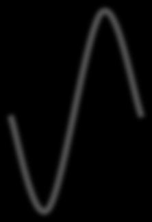
43 Example Streaming (Convolution/Correlation): Assume incoming x is a rectangular pulse (in baseband) and h is also a rectangular pulse A gif animation: redline g(): the sliding filter h(t) blue line f(): the input x() Source: 43
44 Determining the Best h y = (g + w)* h = g*h + w * h = g o + n where w is noise, g o (t) = g*h n = w * h Design objective: maximize peak pulse signalto-noise ratio 44
45 Determining the Best h g o (t) = g*h Assume Gaussian noise, one can derive E[n 2 (T )] = N 0 2 H( f ) 2 df Using Fourier Transform and Convolution Theorem: g o (T ) = G 0 ( f )e j2π ft df = G( f )H( f )e j2π ft df η = G( f )H( f )e j2π ft df N 0 2 H( f ) 2 df 2 45
46 Determining the Best h Apply Schwartz inequality η = G( f )H( f )e j2π ft df N 0 2 H( f ) 2 df 2 x( f )y( f )df x( f ) 2 df 2 y( f ) 2 df equal iff x( f ) = ky *( f ) By considering x( f ) = H( f ) y( f ) = G( f )e j2πtf H opt ( f ) = k[g( f )e j2π ft ]* j2π ft = kg *( f )e 46
47 Determining the Best h j2π ft H opt ( f ) = kg *( f )e η = G( f )H( f )e j2π ft df N 0 2 H( f ) 2 df 2 f = h opt (t) = H opt ( f )e j2π ft = kg *( f )e j2π ft e h opt (t) = kg(t t) f = f = f = f = = kg( f )e j2π ft e = kg( f )e = kg( f )e j2π f (T t) j2π f (T t) j2π ft j2π ft 47
48 Determining Best h to Use x 0 x 1 x 2 x T x 0 x 1 x 2 x T * * * * h T h 2 h 1 h 0 * * * * g 0 g 1 g 2 g T h opt (t) = kg(t t) 48
49 Matched Filter Decision is called Matched filter. Example h opt (t) = kg(t t) h opt (t) = kg(t t) decision time 49
50 Backup Slides 50
51 Modulation 51
Outline. Wireless PHY: Modulation and Demodulation. Recap: Modulation. Admin. Recap: Demod of AM. Page 1. Recap: Amplitude Modulation (AM)
") Outline Wireless PHY: Modulation and Demodulation Admin and recap Amplitude demodulation Digital modulation Y. Richard Yang 9// Admin Assignment posted Recap: Modulation Objective o Frequency assignment
Outline Wireless PHY: Modulation and Demodulation Admin and recap Amplitude demodulation Digital modulation Y. Richard Yang 9// Admin Assignment posted Recap: Modulation Objective o Frequency assignment
CS434/534: Topics in Networked (Networking) Systems
 Systems") CS434/534: Topics in Networked (Networking) Systems Wireless Foundation: Modulation and Demodulation Yang (Richard) Yang Computer Science Department Yale University 208A Watson Email: yry@cs.yale.edu http://zoo.cs.yale.edu/classes/cs434/
CS434/534: Topics in Networked (Networking) Systems Wireless Foundation: Modulation and Demodulation Yang (Richard) Yang Computer Science Department Yale University 208A Watson Email: yry@cs.yale.edu http://zoo.cs.yale.edu/classes/cs434/
Wireless PHY: Modulation and Demodulation
 Wireless PHY: Modulation and Demodulation Y. Richard Yang 09/6/2012 Outline Admin and recap Frequency domain examples Basic concepts of modulation Amplitude modulation Amplitude demodulation frequency
EITG05 Digital Communications
 Fourier transform EITG05 Digital Communications Lecture 4 Bandwidth of Transmitted Signals Michael Lentmaier Thursday, September 3, 08 X(f )F{x(t)} x(t) e jπ ft dt X Re (f )+jx Im (f ) X(f ) e jϕ(f ) x(t)f
Outline. Wireless PHY: Modulation and Demodulation. Admin. Page 1. g(t)e j2πk t dt. G[k] = 1 T. G[k] = = k L. ) = g L (t)e j2π f k t dt.
![Outline. Wireless PHY: Modulation and Demodulation. Admin. Page 1. g(t)e j2πk t dt. G[k] = 1 T. G[k] = = k L. ) = g L (t)e j2π f k t dt.](/thumbs/76/74238457.jpg "Outline. Wireless PHY: Modulation and Demodulation. Admin. Page 1. g(t)e j2πk t dt. G[k] = 1 T. G[k] = = k L. ) = g L (t)e j2π f k t dt.") Outline Wireless PHY: Modulation and Demodulation Y. Richard Yang Admin and recap Basic concepts o modulation Amplitude demodulation requency shiting 09/6/202 2 Admin First assignment to be posted by this
Outline Wireless PHY: Modulation and Demodulation Y. Richard Yang Admin and recap Basic concepts o modulation Amplitude demodulation requency shiting 09/6/202 2 Admin First assignment to be posted by this
Communication Channels
 Communication Channels wires (PCB trace or conductor on IC) optical fiber (attenuation 4dB/km) broadcast TV (50 kw transmit) voice telephone line (under -9 dbm or 110 µw) walkie-talkie: 500 mw, 467 MHz
Outline. Wireless PHY: Modulation and Demodulation. Admin. Page 1. G[k] = 1 T. g(t)e j2πk t dt. G[k] = = k L. ) = g L (t)e j2π f k t dt.
![Outline. Wireless PHY: Modulation and Demodulation. Admin. Page 1. G[k] = 1 T. g(t)e j2πk t dt. G[k] = = k L. ) = g L (t)e j2π f k t dt.](/thumbs/89/97558237.jpg "Outline. Wireless PHY: Modulation and Demodulation. Admin. Page 1. G[k] = 1 T. g(t)e j2πk t dt. G[k] = = k L. ) = g L (t)e j2π f k t dt.") Outline Wireless PHY: Modulation and Demodulation Y. Richard Yang Admin and recap Basic concepts o modulation Amplitude modulation Amplitude demodulation requency shiting 9/6/22 2 Admin First assignment
Outline Wireless PHY: Modulation and Demodulation Y. Richard Yang Admin and recap Basic concepts o modulation Amplitude modulation Amplitude demodulation requency shiting 9/6/22 2 Admin First assignment
Outline. EECS 3213 Fall Sebastian Magierowski York University. Review Passband Modulation. Constellations ASK, FSK, PSK.
 EECS 3213 Fall 2014 L12: Modulation Sebastian Magierowski York University 1 Outline Review Passband Modulation ASK, FSK, PSK Constellations 2 1 Underlying Idea Attempting to send a sequence of digits through
Digital Communication System
 Digital Communication System Purpose: communicate information at required rate between geographically separated locations reliably (quality) Important point: rate, quality spectral bandwidth, power requirements
Objectives. Presentation Outline. Digital Modulation Lecture 03
 Digital Modulation Lecture 03 Inter-Symbol Interference Power Spectral Density Richard Harris Objectives To be able to discuss Inter-Symbol Interference (ISI), its causes and possible remedies. To be able
ENSC327 Communication Systems 27: Digital Bandpass Modulation. (Ch. 7) Jie Liang School of Engineering Science Simon Fraser University
 Jie Liang School of Engineering Science Simon Fraser University") ENSC37 Communication Systems 7: Digital Bandpass Modulation (Ch. 7) Jie Liang School of Engineering Science Simon Fraser University 1 Outline 7.1 Preliminaries 7. Binary Amplitude-Shift Keying (BASK) 7.3
ENSC37 Communication Systems 7: Digital Bandpass Modulation (Ch. 7) Jie Liang School of Engineering Science Simon Fraser University 1 Outline 7.1 Preliminaries 7. Binary Amplitude-Shift Keying (BASK) 7.3
Chapter 7 Multiple Division Techniques for Traffic Channels
 Introduction to Wireless & Mobile Systems Chapter 7 Multiple Division Techniques for Traffic Channels Outline Introduction Concepts and Models for Multiple Divisions Frequency Division Multiple Access
Fund. of Digital Communications Ch. 3: Digital Modulation
 Fund. of Digital Communications Ch. 3: Digital Modulation Klaus Witrisal witrisal@tugraz.at Signal Processing and Speech Communication Laboratory www.spsc.tugraz.at Graz University of Technology November
PULSE SHAPING AND RECEIVE FILTERING
 PULSE SHAPING AND RECEIVE FILTERING Pulse and Pulse Amplitude Modulated Message Spectrum Eye Diagram Nyquist Pulses Matched Filtering Matched, Nyquist Transmit and Receive Filter Combination adaptive components
Chapter-2 SAMPLING PROCESS
 Chapter-2 SAMPLING PROCESS SAMPLING: A message signal may originate from a digital or analog source. If the message signal is analog in nature, then it has to be converted into digital form before it can
Implementation of Digital Signal Processing: Some Background on GFSK Modulation
 Implementation of Digital Signal Processing: Some Background on GFSK Modulation Sabih H. Gerez University of Twente, Department of Electrical Engineering s.h.gerez@utwente.nl Version 5 (March 9, 2016)
Digital Modulation Schemes
 Digital Modulation Schemes 1. In binary data transmission DPSK is preferred to PSK because (a) a coherent carrier is not required to be generated at the receiver (b) for a given energy per bit, the probability
Digital Communication System
 Digital Communication System Purpose: communicate information at certain rate between geographically separated locations reliably (quality) Important point: rate, quality spectral bandwidth requirement
Final Exam Solutions June 14, 2006
 Name or 6-Digit Code: PSU Student ID Number: Final Exam Solutions June 14, 2006 ECE 223: Signals & Systems II Dr. McNames Keep your exam flat during the entire exam. If you have to leave the exam temporarily,
Principles of Communications ECS 332
 Principles of Communications ECS 332 Asst. Prof. Dr. Prapun Suksompong prapun@siit.tu.ac.th 5. Angle Modulation Office Hours: BKD, 6th floor of Sirindhralai building Wednesday 4:3-5:3 Friday 4:3-5:3 Example
CHANNEL ENCODING & DECODING. Binary Interface
 CHANNEL ENCODING & DECODING Input Source Encoder Channel Encoder Binary Interface Channel Output Source Decoder Channel Decoder 1 Simplest Example of channel encoding A sequence of binary digits is mapped,
EE4601 Communication Systems
 4601 Communication Systems Week 8 Binary Modulated Signal Sets Non-Binary Signal Sets 0 c 2011, Georgia Institute of Technology (lect8 1) Binary PSK (BPSK) With BPSK information is transmitted in the carrier
COSC 3213: Computer Networks I: Chapter 3 Handout #4. Instructor: Dr. Marvin Mandelbaum Department of Computer Science York University Section A
 COSC 3213: Computer Networks I: Chapter 3 Handout #4 Instructor: Dr. Marvin Mandelbaum Department of Computer Science York University Section A Topics: 1. Line Coding: Unipolar, Polar,and Inverted ; Bipolar;
Revision of Lecture 3
 Revision of Lecture 3 Modulator/demodulator Basic operations of modulation and demodulation Complex notations for modulation and demodulation Carrier recovery and timing recovery This lecture: bits map
Project I: Phase Tracking and Baud Timing Correction Systems
 Project I: Phase Tracking and Baud Timing Correction Systems ECES 631, Prof. John MacLaren Walsh, Ph. D. 1 Purpose In this lab you will encounter the utility of the fundamental Fourier and z-transform
Refresher on Digital Communications Channel, Modulation, and Demodulation
 Refresher on Digital Communications Channel, Modulation, and Demodulation Philippe Ciblat Université Paris-Saclay & Télécom ParisTech Outline Section 1: Digital Communication scheme Section 2: A toy example
Mobile & Wireless Networking. Lecture 2: Wireless Transmission (2/2)
") 192620010 Mobile & Wireless Networking Lecture 2: Wireless Transmission (2/2) [Schiller, Section 2.6 & 2.7] [Reader Part 1: OFDM: An architecture for the fourth generation] Geert Heijenk Outline of Lecture
192620010 Mobile & Wireless Networking Lecture 2: Wireless Transmission (2/2) [Schiller, Section 2.6 & 2.7] [Reader Part 1: OFDM: An architecture for the fourth generation] Geert Heijenk Outline of Lecture
3/26/18. Lecture 3 EITN STRUCTURE OF A WIRELESS COMMUNICATION LINK
 Lecture 3 EITN75 208 STRUCTURE OF A WIRELESS COMMUNICATION LINK 2 A simple structure Speech Data A/D Speech encoder Encrypt. Chann. encoding Modulation Key Speech D/A Speech decoder Decrypt. Chann. decoding
Lecture 2 Review of Signals and Systems: Part 1. EE4900/EE6720 Digital Communications
 EE4900/EE6420: Digital Communications 1 Lecture 2 Review of Signals and Systems: Part 1 Block Diagrams of Communication System Digital Communication System 2 Informatio n (sound, video, text, data, ) Transducer
Wireless Networks (PHY): Design for Diversity
: Design for Diversity") Wireless Networks (PHY): Design for Diversity Y. Richard Yang 9/20/2012 Outline Admin and recap Design for diversity 2 Admin Assignment 1 questions Assignment 1 office hours Thursday 3-4 @ AKW 307A 3 Recap:
Wireless Networks (PHY): Design for Diversity Y. Richard Yang 9/20/2012 Outline Admin and recap Design for diversity 2 Admin Assignment 1 questions Assignment 1 office hours Thursday 3-4 @ AKW 307A 3 Recap:
University of Toronto Electrical & Computer Engineering ECE 316, Winter 2015 Thursday, February 12, Test #1
 Name: Student No.: University of Toronto Electrical & Computer Engineering ECE 36, Winter 205 Thursday, February 2, 205 Test # Professor Dimitrios Hatzinakos Professor Deepa Kundur Duration: 50 minutes
F I R Filter (Finite Impulse Response)
") F I R Filter (Finite Impulse Response) Ir. Dadang Gunawan, Ph.D Electrical Engineering University of Indonesia The Outline 7.1 State-of-the-art 7.2 Type of Linear Phase Filter 7.3 Summary of 4 Types FIR
F I R Filter (Finite Impulse Response) Ir. Dadang Gunawan, Ph.D Electrical Engineering University of Indonesia The Outline 7.1 State-of-the-art 7.2 Type of Linear Phase Filter 7.3 Summary of 4 Types FIR
Outline Chapter 4: Orthogonal Frequency Division Multiplexing
 Outline Chapter 4: Orthogonal Frequency Division Multiplexing Fading Channel Flat fading channel Frequency selective channel ISI Single Carrier Equalization Orthogonal Frequency Division Multiplexing Principle
Experiments #6. Convolution and Linear Time Invariant Systems
 Experiments #6 Convolution and Linear Time Invariant Systems 1) Introduction: In this lab we will explain how to use computer programs to perform a convolution operation on continuous time systems and
Mobile Communication An overview Lesson 03 Introduction to Modulation Methods
 Mobile Communication An overview Lesson 03 Introduction to Modulation Methods Oxford University Press 2007. All rights reserved. 1 Modulation The process of varying one signal, called carrier, according
DIGITAL COMMUNICATIONS SYSTEMS. MSc in Electronic Technologies and Communications
 DIGITAL COMMUNICATIONS SYSTEMS MSc in Electronic Technologies and Communications Bandpass binary signalling The common techniques of bandpass binary signalling are: - On-off keying (OOK), also known as
Lecture 3: Wireless Physical Layer: Modulation Techniques. Mythili Vutukuru CS 653 Spring 2014 Jan 13, Monday
 Lecture 3: Wireless Physical Layer: Modulation Techniques Mythili Vutukuru CS 653 Spring 2014 Jan 13, Monday Modulation We saw a simple example of amplitude modulation in the last lecture Modulation how
Digital Signal Analysis
 Digital Signal Analysis Objectives - Provide a digital modulation overview - Review common digital radio impairments Digital Modulation Overview Signal Characteristics to Modify Polar Display / IQ Relationship
Design of a Transceiver for 3G DECT Physical Layer. - Rohit Budhiraja
 Design of a Transceiver for 3G DECT Physical Layer - Rohit Budhiraja The Big Picture 2G DECT Binary GFSK 1.152Mbps 3G DECT M-ary DPSK 3.456 Mbps DECT - Digital Enhanced Cordless Telecommunications Overview
DSP First. Laboratory Exercise #7. Everyday Sinusoidal Signals
 DSP First Laboratory Exercise #7 Everyday Sinusoidal Signals This lab introduces two practical applications where sinusoidal signals are used to transmit information: a touch-tone dialer and amplitude
CS434/534: Topics in Networked (Networking) Systems
 Systems") CS434/534: Topics in Networked (Networking) Systems Wireless Foundation: Diversity Design for Flat fading Yang (Richard) Yang Computer Science Department Yale University 208A Watson Email: yry@cs.yale.edu
CS434/534: Topics in Networked (Networking) Systems Wireless Foundation: Diversity Design for Flat fading Yang (Richard) Yang Computer Science Department Yale University 208A Watson Email: yry@cs.yale.edu
Digital modulations (part 1)
") Digital modulations (part 1) Outline : 1. Digital modulations definition. Classic linear modulations.1 Power spectral density. Amplitude digital modulation (ASK).3 Phase digital modulation (PSK).4 Quadrature
Digital modulations (part 1) Outline : 1. Digital modulations definition. Classic linear modulations.1 Power spectral density. Amplitude digital modulation (ASK).3 Phase digital modulation (PSK).4 Quadrature
Receiver Designs for the Radio Channel
 Receiver Designs for the Radio Channel COS 463: Wireless Networks Lecture 15 Kyle Jamieson [Parts adapted from C. Sodini, W. Ozan, J. Tan] Today 1. Delay Spread and Frequency-Selective Fading 2. Time-Domain
Outline. Analog Communications. Lecture 03 Linear Modulation. Linear Modulation. Double Side Band (DSB) Modulation. Pierluigi SALVO ROSSI
 Modulation. Pierluigi SALVO ROSSI") Outline Analog Communications Lecture 03 Linear Modulation Pierluigi SALVO ROSSI Department of Industrial and Information Engineering Second University of Naples Via Roma 29, 81031 Aversa (CE), Italy homepage:
Outline Analog Communications Lecture 03 Linear Modulation Pierluigi SALVO ROSSI Department of Industrial and Information Engineering Second University of Naples Via Roma 29, 81031 Aversa (CE), Italy homepage:
Practical issue: Group definition. TSTE17 System Design, CDIO. Quadrature Amplitude Modulation (QAM) Components of a digital communication system
 Components of a digital communication system") 1 2 TSTE17 System Design, CDIO Introduction telecommunication OFDM principle How to combat ISI How to reduce out of band signaling Practical issue: Group definition Project group sign up list will be put
1 2 TSTE17 System Design, CDIO Introduction telecommunication OFDM principle How to combat ISI How to reduce out of band signaling Practical issue: Group definition Project group sign up list will be put
ECE5713 : Advanced Digital Communications
 ECE5713 : Advanced Digital Communications Bandpass Modulation MPSK MASK, OOK MFSK 04-May-15 Advanced Digital Communications, Spring-2015, Week-8 1 In-phase and Quadrature (I&Q) Representation Any bandpass
Other Modulation Techniques - CAP, QAM, DMT
 Other Modulation Techniques - CAP, QAM, DMT Prof. David Johns (johns@eecg.toronto.edu) (www.eecg.toronto.edu/~johns) slide 1 of 47 Complex Signals Concept useful for describing a pair of real signals Let
QUESTION BANK SUBJECT: DIGITAL COMMUNICATION (15EC61)
") QUESTION BANK SUBJECT: DIGITAL COMMUNICATION (15EC61) Module 1 1. Explain Digital communication system with a neat block diagram. 2. What are the differences between digital and analog communication systems?
QUESTION BANK SUBJECT: DIGITAL COMMUNICATION (15EC61) Module 1 1. Explain Digital communication system with a neat block diagram. 2. What are the differences between digital and analog communication systems?
HW 6 Due: November 3, 10:39 AM (in class)
") ECS 332: Principles of Communications 2015/1 HW 6 Due: November 3, 10:39 AM (in class) Lecturer: Prapun Suksompong, Ph.D. Instructions (a) ONE part of a question will be graded (5 pt). Of course, you do
ECS 332: Principles of Communications 2015/1 HW 6 Due: November 3, 10:39 AM (in class) Lecturer: Prapun Suksompong, Ph.D. Instructions (a) ONE part of a question will be graded (5 pt). Of course, you do
Presentation Outline. Advisors: Dr. In Soo Ahn Dr. Thomas L. Stewart. Team Members: Luke Vercimak Karl Weyeneth. Karl. Luke
 Bradley University Department of Electrical and Computer Engineering Senior Capstone Project Presentation May 2nd, 2006 Team Members: Luke Vercimak Karl Weyeneth Advisors: Dr. In Soo Ahn Dr. Thomas L.
Chapter 2 Overview - 1 -
 Chapter 2 Overview Part 1 (last week) Digital Transmission System Frequencies, Spectrum Allocation Radio Propagation and Radio Channels Part 2 (today) Modulation, Coding, Error Correction Part 3 (next
Continuous-Time Signal Analysis FOURIER Transform - Applications DR. SIGIT PW JAROT ECE 2221
 Continuous-Time Signal Analysis FOURIER Transform - Applications DR. SIGIT PW JAROT ECE 2221 Inspiring Message from Imam Shafii You will not acquire knowledge unless you have 6 (SIX) THINGS Intelligence
END-OF-YEAR EXAMINATIONS ELEC321 Communication Systems (D2) Tuesday, 22 November 2005, 9:20 a.m. Three hours plus 10 minutes reading time.
 Tuesday, 22 November 2005, 9:20 a.m. Three hours plus 10 minutes reading time.") END-OF-YEAR EXAMINATIONS 2005 Unit: Day and Time: Time Allowed: ELEC321 Communication Systems (D2) Tuesday, 22 November 2005, 9:20 a.m. Three hours plus 10 minutes reading time. Total Number of Questions:
END-OF-YEAR EXAMINATIONS 2005 Unit: Day and Time: Time Allowed: ELEC321 Communication Systems (D2) Tuesday, 22 November 2005, 9:20 a.m. Three hours plus 10 minutes reading time. Total Number of Questions:
Biomedical Signals. Signals and Images in Medicine Dr Nabeel Anwar
 Biomedical Signals Signals and Images in Medicine Dr Nabeel Anwar Noise Removal: Time Domain Techniques 1. Synchronized Averaging (covered in lecture 1) 2. Moving Average Filters (today s topic) 3. Derivative
ECE438 - Laboratory 7a: Digital Filter Design (Week 1) By Prof. Charles Bouman and Prof. Mireille Boutin Fall 2015
 By Prof. Charles Bouman and Prof. Mireille Boutin Fall 2015") Purdue University: ECE438 - Digital Signal Processing with Applications 1 ECE438 - Laboratory 7a: Digital Filter Design (Week 1) By Prof. Charles Bouman and Prof. Mireille Boutin Fall 2015 1 Introduction
Purdue University: ECE438 - Digital Signal Processing with Applications 1 ECE438 - Laboratory 7a: Digital Filter Design (Week 1) By Prof. Charles Bouman and Prof. Mireille Boutin Fall 2015 1 Introduction
EE228 Applications of Course Concepts. DePiero
 EE228 Applications of Course Concepts DePiero Purpose Describe applications of concepts in EE228. Applications may help students recall and synthesize concepts. Also discuss: Some advanced concepts Highlight
2.1 BASIC CONCEPTS Basic Operations on Signals Time Shifting. Figure 2.2 Time shifting of a signal. Time Reversal.
 1 2.1 BASIC CONCEPTS 2.1.1 Basic Operations on Signals Time Shifting. Figure 2.2 Time shifting of a signal. Time Reversal. 2 Time Scaling. Figure 2.4 Time scaling of a signal. 2.1.2 Classification of Signals
Transmission Fundamentals
 College of Computer & Information Science Wireless Networks Northeastern University Lecture 1 Transmission Fundamentals Signals Data rate and bandwidth Nyquist sampling theorem Shannon capacity theorem
Revision of Wireless Channel
 Revision of Wireless Channel Quick recap system block diagram CODEC MODEM Wireless Channel Previous three lectures looked into wireless mobile channels To understand mobile communication technologies,
EE3723 : Digital Communications
 EE3723 : Digital Communications Week 8-9: Bandpass Modulation MPSK MASK, OOK MFSK 04-May-15 Muhammad Ali Jinnah University, Islamabad - Digital Communications - EE3723 1 In-phase and Quadrature (I&Q) Representation
Theory of Telecommunications Networks
 Theory of Telecommunications Networks Anton Čižmár Ján Papaj Department of electronics and multimedia telecommunications CONTENTS Preface... 5 1 Introduction... 6 1.1 Mathematical models for communication
Lab 3.0. Pulse Shaping and Rayleigh Channel. Faculty of Information Engineering & Technology. The Communications Department
 Faculty of Information Engineering & Technology The Communications Department Course: Advanced Communication Lab [COMM 1005] Lab 3.0 Pulse Shaping and Rayleigh Channel 1 TABLE OF CONTENTS 2 Summary...
Lab course Analog Part of a State-of-the-Art Mobile Radio Receiver
 Communication Technology Laboratory Wireless Communications Group Prof. Dr. A. Wittneben ETH Zurich, ETF, Sternwartstrasse 7, 8092 Zurich Tel 41 44 632 36 11 Fax 41 44 632 12 09 Lab course Analog Part
Chapter 2: Signal Representation
 Chapter 2: Signal Representation Aveek Dutta Assistant Professor Department of Electrical and Computer Engineering University at Albany Spring 2018 Images and equations adopted from: Digital Communications
Admin. OFDM, Mobile Software Development Framework. Recap. Multiple Carrier Modulation. Benefit of Symbol Rate on ISI.
 Admin. OFDM, Mobile Software Development Framework Homework to be posted by Friday Start to think about project 9/7/01 Y. Richard Yang 1 Recap Inter-Symbol Interference (ISI) Handle band limit ISI Handle
Communications IB Paper 6 Handout 2: Analogue Modulation
 Communications IB Paper 6 Handout 2: Analogue Modulation Jossy Sayir Signal Processing and Communications Lab Department of Engineering University of Cambridge jossy.sayir@eng.cam.ac.uk Lent Term c Jossy
Module 4. Signal Representation and Baseband Processing. Version 2 ECE IIT, Kharagpur
 Module 4 Signal Representation and Baseband Processing Lesson 1 Nyquist Filtering and Inter Symbol Interference After reading this lesson, you will learn about: Power spectrum of a random binary sequence;
Linear Time-Invariant Systems
 Linear Time-Invariant Systems Modules: Wideband True RMS Meter, Audio Oscillator, Utilities, Digital Utilities, Twin Pulse Generator, Tuneable LPF, 100-kHz Channel Filters, Phase Shifter, Quadrature Phase
ELT Receiver Architectures and Signal Processing Fall Mandatory homework exercises
 ELT-44006 Receiver Architectures and Signal Processing Fall 2014 1 Mandatory homework exercises - Individual solutions to be returned to Markku Renfors by email or in paper format. - Solutions are expected
Digital Communication
 Digital Communication (ECE4058) Electronics and Communication Engineering Hanyang University Haewoon Nam Lecture 1 1 Digital Band Pass Modulation echnique Digital and-pass modulation techniques Amplitude-shift
Wireless Communication Fading Modulation
 EC744 Wireless Communication Fall 2008 Mohamed Essam Khedr Department of Electronics and Communications Wireless Communication Fading Modulation Syllabus Tentatively Week 1 Week 2 Week 3 Week 4 Week 5
The University of Texas at Austin Dept. of Electrical and Computer Engineering Final Exam
 The University of Texas at Austin Dept. of Electrical and Computer Engineering Final Exam Date: December 18, 2017 Course: EE 313 Evans Name: Last, First The exam is scheduled to last three hours. Open
Oluwole Oyetoke 1, 2 Dr. O.E Agboje. Covenant University, Ota, Nigeria
 Design and Implementation of A Java Based Simulation Package for Spectrum Analysis, Digital Filtration and Modulation as A Teaching Aid for Data Communication Oluwole Oyetoke 1, 2 Dr. O.E Agboje 1, 2 Covenant
Chapter 2 Overview - 1 -
 Chapter 2 Overview Part 1 (last week) Digital Transmission System Frequencies, Spectrum Allocation Radio Propagation and Radio Channels Part 2 (today) Modulation, Coding, Error Correction Part 3 (next
Final Exam. EE313 Signals and Systems. Fall 1999, Prof. Brian L. Evans, Unique No
 Final Exam EE313 Signals and Systems Fall 1999, Prof. Brian L. Evans, Unique No. 14510 December 11, 1999 The exam is scheduled to last 50 minutes. Open books and open notes. You may refer to your homework
SIGNALS AND SYSTEMS LABORATORY 13: Digital Communication
 SIGNALS AND SYSTEMS LABORATORY 13: Digital Communication INTRODUCTION Digital Communication refers to the transmission of binary, or digital, information over analog channels. In this laboratory you will
1. Clearly circle one answer for each part.
 TB 1-9 / Exam Style Questions 1 EXAM STYLE QUESTIONS Covering Chapters 1-9 of Telecommunication Breakdown 1. Clearly circle one answer for each part. (a) TRUE or FALSE: Absolute bandwidth is never less
Spread spectrum. Outline : 1. Baseband 2. DS/BPSK Modulation 3. CDM(A) system 4. Multi-path 5. Exercices. Exercise session 7 : Spread spectrum 1
 system 4. Multi-path 5. Exercices. Exercise session 7 : Spread spectrum 1") Spread spectrum Outline : 1. Baseband 2. DS/BPSK Modulation 3. CDM(A) system 4. Multi-path 5. Exercices Exercise session 7 : Spread spectrum 1 1. Baseband +1 b(t) b(t) -1 T b t Spreading +1-1 T c t m(t)
Spread spectrum Outline : 1. Baseband 2. DS/BPSK Modulation 3. CDM(A) system 4. Multi-path 5. Exercices Exercise session 7 : Spread spectrum 1 1. Baseband +1 b(t) b(t) -1 T b t Spreading +1-1 T c t m(t)
Experimenting with Orthogonal Frequency-Division Multiplexing OFDM Modulation
 FUTEBOL Federated Union of Telecommunications Research Facilities for an EU-Brazil Open Laboratory Experimenting with Orthogonal Frequency-Division Multiplexing OFDM Modulation The content of these slides
DT Filters 2/19. Atousa Hajshirmohammadi, SFU
 1/19 ENSC380 Lecture 23 Objectives: Signals and Systems Fourier Analysis: Discrete Time Filters Analog Communication Systems Double Sideband, Sub-pressed Carrier Modulation (DSBSC) Amplitude Modulation
Chapter 2. Signals and Spectra
 Chapter 2 Signals and Spectra Outline Properties of Signals and Noise Fourier Transform and Spectra Power Spectral Density and Autocorrelation Function Orthogonal Series Representation of Signals and Noise
Digital Communications: Introduction to Key Concepts and their relation to Acoustic Water Column Channels. Ross Murch and Vincent Lau
 Digital Communications: Introduction to Key Concepts and their relation to Acoustic Water Column Channels Ross Murch and Vincent Lau 2 Outline- Key Concepts Features of Acoustic Water Column Channel Digital
Signal Processing Techniques for Software Radio
 Signal Processing Techniques for Software Radio Behrouz Farhang-Boroujeny Department of Electrical and Computer Engineering University of Utah c 2007, Behrouz Farhang-Boroujeny, ECE Department, University
Chapter 6 Passband Data Transmission
 Chapter 6 Passband Data Transmission Passband Data Transmission concerns the Transmission of the Digital Data over the real Passband channel. 6.1 Introduction Categories of digital communications (ASK/PSK/FSK)
Digital Modulation. Kate Ching-Ju Lin ( 林靖茹 ) Academia Sinica
 Academia Sinica") Digital Modulation Kate Ching-Ju Lin ( 林靖茹 ) Academia Sinica Map bits to signals Modulation TX bit stream x(t) 1 0 1 1 0 modula7on signal s(t) wireless channel Map signals to bits Demodulation TX RX bit
Digital Modulation Kate Ching-Ju Lin ( 林靖茹 ) Academia Sinica Map bits to signals Modulation TX bit stream x(t) 1 0 1 1 0 modula7on signal s(t) wireless channel Map signals to bits Demodulation TX RX bit
ECEn 665: Antennas and Propagation for Wireless Communications 131. s(t) = A c [1 + αm(t)] cos (ω c t) (9.27)
![ECEn 665: Antennas and Propagation for Wireless Communications 131. s(t) = A c [1 + αm(t)] cos (ω c t) (9.27)](/thumbs/88/116957690.jpg "ECEn 665: Antennas and Propagation for Wireless Communications 131. s(t) = A c [1 + αm(t)] cos (ω c t) (9.27)") ECEn 665: Antennas and Propagation for Wireless Communications 131 9. Modulation Modulation is a way to vary the amplitude and phase of a sinusoidal carrier waveform in order to transmit information. When
ECEn 665: Antennas and Propagation for Wireless Communications 131 9. Modulation Modulation is a way to vary the amplitude and phase of a sinusoidal carrier waveform in order to transmit information. When
Detection and Estimation of Signals in Noise. Dr. Robert Schober Department of Electrical and Computer Engineering University of British Columbia
 Detection and Estimation of Signals in Noise Dr. Robert Schober Department of Electrical and Computer Engineering University of British Columbia Vancouver, August 24, 2010 2 Contents 1 Basic Elements
Chapter 3 Data Transmission COSC 3213 Summer 2003
 Chapter 3 Data Transmission COSC 3213 Summer 2003 Courtesy of Prof. Amir Asif Definitions 1. Recall that the lowest layer in OSI is the physical layer. The physical layer deals with the transfer of raw
Chapter 2: Wireless Transmission. Mobile Communications. Spread spectrum. Multiplexing. Modulation. Frequencies. Antenna. Signals
 Mobile Communications Chapter 2: Wireless Transmission Frequencies Multiplexing Signals Spread spectrum Antenna Modulation Signal propagation Cellular systems Prof. Dr.-Ing. Jochen Schiller, http://www.jochenschiller.de/
Columbia University. Principles of Communication Systems ELEN E3701. Spring Semester May Final Examination
 1 Columbia University Principles of Communication Systems ELEN E3701 Spring Semester- 2006 9 May 2006 Final Examination Length of Examination- 3 hours Answer All Questions Good Luck!!! I. Kalet 2 Problem
The Communications Channel (Ch.11):
:") ECE-5 Phil Schniter February 5, 8 The Communications Channel (Ch.): The eects o signal propagation are usually modeled as: ECE-5 Phil Schniter February 5, 8 Filtering due to Multipath Propagation: The
ECE-5 Phil Schniter February 5, 8 The Communications Channel (Ch.): The eects o signal propagation are usually modeled as: ECE-5 Phil Schniter February 5, 8 Filtering due to Multipath Propagation: The
ECE 3500: Fundamentals of Signals and Systems (Fall 2015) Lab 4: Binary Phase-Shift Keying Modulation and Demodulation
 Lab 4: Binary Phase-Shift Keying Modulation and Demodulation") ECE 500: Fundamentals of Signals and Systems (Fall 2015) Lab 4: Binary Phase-Shift Keying Modulation and Demodulation Files necessary to complete this assignment: none Deliverables Due: Before Dec. 18th
ECE 500: Fundamentals of Signals and Systems (Fall 2015) Lab 4: Binary Phase-Shift Keying Modulation and Demodulation Files necessary to complete this assignment: none Deliverables Due: Before Dec. 18th
Lecture #11 Overview. Vector representation of signal waveforms. Two-dimensional signal waveforms. 1 ENGN3226: Digital Communications L#
 Lecture #11 Overview Vector representation of signal waveforms Two-dimensional signal waveforms 1 ENGN3226: Digital Communications L#11 00101011 Geometric Representation of Signals We shall develop a geometric
Costas Loop. Modules: Sequence Generator, Digital Utilities, VCO, Quadrature Utilities (2), Phase Shifter, Tuneable LPF (2), Multiplier
, Phase Shifter, Tuneable LPF (2), Multiplier") Costas Loop Modules: Sequence Generator, Digital Utilities, VCO, Quadrature Utilities (2), Phase Shifter, Tuneable LPF (2), Multiplier 0 Pre-Laboratory Reading Phase-shift keying that employs two discrete
Costas Loop Modules: Sequence Generator, Digital Utilities, VCO, Quadrature Utilities (2), Phase Shifter, Tuneable LPF (2), Multiplier 0 Pre-Laboratory Reading Phase-shift keying that employs two discrete
Chpater 8 Digital Transmission through Bandlimited AWGN Channels
 Chapter 8. Digital Transmission through Bandlimited AWGN Channels - 1-1 st Semester, 008 Chpater 8 Digital Transmission through Bandlimited AWGN Channels Text. [1] J. G. Proakis and M. Salehi, Communication
Solution to Chapter 4 Problems
 Solution to Chapter 4 Problems Problem 4.1 1) Since F[sinc(400t)]= 1 modulation index 400 ( f 400 β f = k f max[ m(t) ] W Hence, the modulated signal is ), the bandwidth of the message signal is W = 00
THIS work focus on a sector of the hardware to be used
 DISSERTATION ON ELECTRICAL AND COMPUTER ENGINEERING 1 Development of a Transponder for the ISTNanoSAT (November 2015) Luís Oliveira luisdeoliveira@tecnico.ulisboa.pt Instituto Superior Técnico Abstract
Lecture 10. Digital Modulation
 Digital Modulation Lecture 10 On-Off keying (OOK), or amplitude shift keying (ASK) Phase shift keying (PSK), particularly binary PSK (BPSK) Frequency shift keying Typical spectra Modulation/demodulation
Amplitude Modulation, II
 Amplitude Modulation, II Single sideband modulation (SSB) Vestigial sideband modulation (VSB) VSB spectrum Modulator and demodulator NTSC TV signsals Quadrature modulation Spectral efficiency Modulator
a) Abasebanddigitalcommunicationsystemhasthetransmitterfilterg(t) thatisshowninthe figure, and a matched filter at the receiver.
 Abasebanddigitalcommunicationsystemhasthetransmitterfilterg(t) thatisshowninthe figure, and a matched filter at the receiver.") DIGITAL COMMUNICATIONS PART A (Time: 60 minutes. Points 4/0) Last Name(s):........................................................ First (Middle) Name:.................................................
DIGITAL COMMUNICATIONS PART A (Time: 60 minutes. Points 4/0) Last Name(s):........................................................ First (Middle) Name:.................................................