Real Time Jitter Analysis
|
|
|
- Lucinda Brown
- 6 years ago
- Views:
Transcription
1 Real Time Jitter Analysis
2 Agenda ı Background on jitter measurements Definition Measurement types: parametric, graphical ı Jitter noise floor ı Statistical analysis of jitter Jitter structure Jitter PDF s PDF models, CDF and BER ı Jitter track analysis ı Jitter measurement methods Batch mode Real time ı Measurement example 2
3 Jitter Definition ı Short term variation in the timing of a signal Many parameters are included in jitter Frequency, period, phase, etc. ı Limited to timing variations at higher frequencies > 10 Hz (telecom definition) > a defined minimum frequency usually a fraction of the bit rate ( for example 1/1667 ) Hold time D Setup time clk Q 3
4 Jitter Measurements
5 Parametric Timing Measurement sampled data Interpolated samples Threshold crossing time threshold 50 ps 50 ps ı Sample points are interpolated to provide increased resolution Sinx/x interpolation is ideal ı Crossing point determined by linear interpolation between points on either side of the threshold Floating point computation Precision is limited to the floating point number 5
6 Graphical Timing Measurement - persistence display threshold Trigger l Simple setup l Precision limited to pixel resolution jitter l Single waveform period introduces trigger jitter l No control over jitter transfer function high pass characteristic
7 Instrument Limitations for Jitter Analysis V N time V A Δt s Δt l
8 Jitter and Bandwidth ı Sufficient bandwidth is required to measure a digital signal (clock or data) ı This is normally stated in terms of multiples of the fundamental frequency of the signal Fundamental = the clock frequency or ½ the bit rate Typical requirement = 5 x the fundamental ı Requirement based on the harmonics of a square wave Decrease with 1/f from the carrier - 13 db at 3x, -26 db at 5x for an ideal square wave Real signals typically much lower than this ı Noise and slew rate trade off Noise and slew rate are proportional to bandwidth ( ~ktb) For a given slew rate the minimum jitter noise floor is achieved at a bandwidth of B = f 8

9 Jitter Noise Floor (10 MHz clock) 15 mv RMS noise JNF =.015/2.16e9 = 6.8 ps 9
10 Jitter Noise Floor (825 MHz sine wave) 1 mv RMS noise JNF = 0.001/6e8 = 1.6 ps 10
11 Jitter is a Random Process ı Jitter is a random process that is a combination of random and deterministic sources ı The jitter histogram is used as an estimate of the probability density function (PDF) of the timing values (period, cycle-cycle, N-cycle, TIE) ı A model is fit to the estimated pdf and is used to predict the range of timing values for any sample size Referred to as the total jitter The sample size is defined in terms of an equivalent bit error rate 11
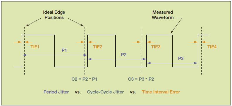
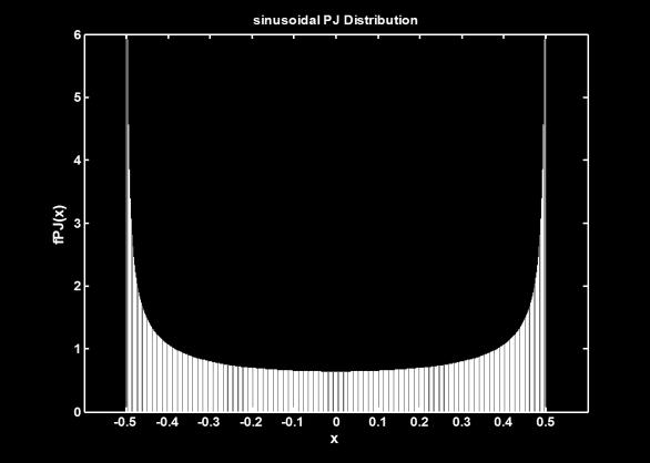
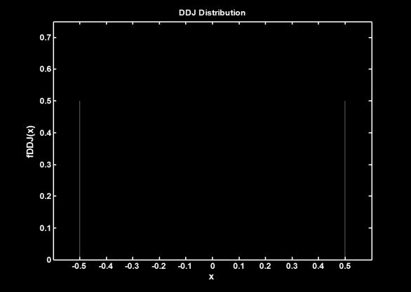
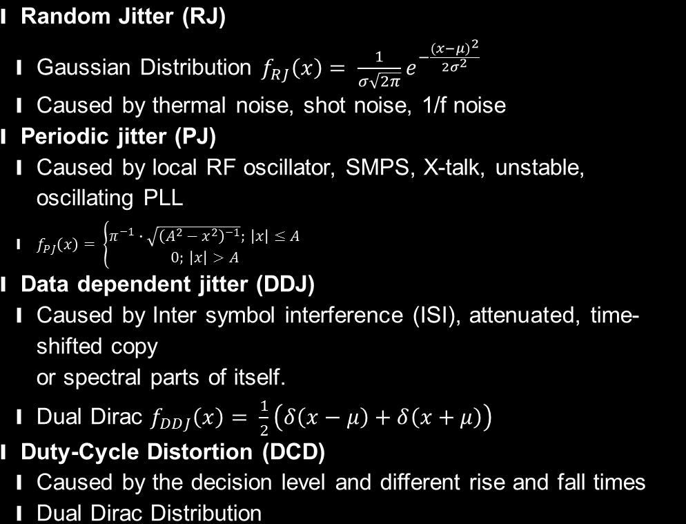
12 Jitter Structure Total Jitter (TJ) Deterministic Jitter (DJ) (bounded) Random Jitter (RJ) (unbounded) Duty-Cycle Distortion (DCD) Data-Dependant Jitter (DDJ) Periodic Jitter (PJ)
13 Probability Density Functions ı The PDF is a function that gives the probability that a random variable takes on a specific value ı In the case of jitter, this is the probability that a transition happens at a specific time from its expected location ı The histogram of a random measurement is an estimate of the PDF for that measurement from which the analytic function can be derived this is the essence of jitter measurement 13


14 Types of Jitter

15 Random Jitter (Gaussian Model) # Measurements 100 1,000 5,000 10, ,000 1,000,000 5,000, ,000,000 1,000,000,000,000 Peak-to peak (s) ±2.1 ±2.9 ±3.4 ±3.5 ±4.1 ±4.6 ±5.1 ±6.0 ±7.0 In theory, the peak to peak value of random signal jitter will grow to without bound. To define the random jitter you must specify a measurement time. 15
16 The Dual Dirac Jitter Model Fit Gaussian curve to the left and right sides of estimated jitter PDF (i.e. the measured normalized histogram) Separation of the mean values gives Dj(d-d) Standard deviation gives Rj Dj(d-d) and s are chosen to best fit the measured histogram in the tails Model Predicts jitter for low bit error rates Note that the model does not fit the central part of the measured distribution Tj Rj s Dj( d - d ) - Q G ( BER)* Rj Dj( d -d ) R L 16


17 BER Jitter and Bit Error Rate Jitter PDF Assumption: Bit errors are caused by signal transitions at the wrong time 0 UI 1
 The width of this curve at the specified BER (or confidence interval) gives the total jitter 18 Total Jitter Curve CDF (total jitter)")
18 The specified BER is another way of expressing a confidence interval or observation time Total jitter is determined by integrating the probability density function (PDF) separately from the left and right sides to determine the cumulative probability density (CDF) The width of this curve at the specified BER (or confidence interval) gives the total jitter 18 Total Jitter Curve CDF (total jitter) PDF Total jitter and PDF for a Gaussian distribution with standard deviation = 1

19 Jitter Track ı ı Display of measurement results: time-correlated to waveform Useful to analyze any changes in the signal

20 Jitter Track Analysis Functions Time Domain Waveform Spectrum Track curve Histogram
21 Jitter measurement methods Oscilloscope is the primary instrument for jitter measurement Measurement of clock and data signals Wide range of measurement types (period, cycle to cycle, TIE, etc) Measurement methods used in oscilloscopes Real time (triggered) Batch mode

22 Batch Mode Jitter Measurement Analyze long signal acquisition Software clock recovery applied to timing data Many analysis features (frequency, time, statistical)

23 Real time Digital Clock Recovery Real time acquisition similar to triggered mode No CDR or trigger jitter Loop bandwidth not limited by acquisition window
24 Limitations of Batch Mode Jitter Measurement Inherent low frequency cutoff due to windowing Large time gaps in acquisition obscure transient jitter Generally impossible to measure long stress data patterns Discontinuous phase tracking can cause phase "slipping"
25 Acquisition Window T = N/f s (400e3 Samples)/20e9 S/s) = 20 us (100e6 Samples)/(20e9 S/s) = 5 ms
26 Transient jitter
27 1 edge Jitter Measurement With Transient Error 100 M 20x10 9 S/s Processing time 1 us
28 Transient jitter: 5 MHz clock with 1 runt/sec. 28
29 Summary ı Jitter measurements are performed on sampled signals using an oscilloscope Parametric and graphical methods Noise limits measurement sensitivity along with signal slew rate ı The most accurate method for measuring jitter uses a batch mode method Long acquisition followed by post processing in software Assumes stationary jitter statistics Limits low minimum jitter rate ı Real time jitter measurement uses graphical method combined with digital clock recovery Distributed measurement over time Measurement of transient jitter Long stress patterns 29
Jitter analysis with the R&S RTO oscilloscope
 Jitter analysis with the R&S RTO oscilloscope Jitter can significantly impair digital systems and must therefore be analyzed and characterized in detail. The R&S RTO oscilloscope in combination with the
Understanding Apparent Increasing Random Jitter with Increasing PRBS Test Pattern Lengths
 JANUARY 28-31, 2013 SANTA CLARA CONVENTION CENTER Understanding Apparent Increasing Random Jitter with Increasing PRBS Test Pattern Lengths 9-WP6 Dr. Martin Miller The Trend and the Concern The demand
An Introduction to Jitter Analysis. WAVECREST Feb 1,
 An Introduction to Jitter Analysis WAVECREST Feb 1, 2000 1 Traditional View Of Jitter WAVECREST Feb 1, 2000 2 Jitter - What is Jitter? The deviation from the ideal timing of an event. The reference event
Jitter in Digital Communication Systems, Part 1
 Application Note: HFAN-4.0.3 Rev.; 04/08 Jitter in Digital Communication Systems, Part [Some parts of this application note first appeared in Electronic Engineering Times on August 27, 200, Issue 8.] AVAILABLE
Student Research & Creative Works
 Scholars' Mine Masters Theses Student Research & Creative Works Summer 216 Study jitter amplification of a passive channel and investigation of S 21 magnitude extraction methodologies using a pattern generator
Generating Jitter for Fibre Channel Compliance Testing
 Application Note: HFAN-4.5.2 Rev 0; 12/00 Generating Jitter for Fibre Channel Compliance Testing MAXIM High-Frequency/Fiber Communications Group 4hfan452.doc 01/02/01 Generating Jitter for Fibre Channel
Keysight Technologies Precision Jitter Analysis Using the Keysight 86100C DCA-J. Application Note
 Keysight Technologies Precision Jitter Analysis Using the Keysight 86100C DCA-J Application Note Introduction The extremely wide bandwidth of equivalent-time sampling oscilloscopes makes them the tool
Jitter Measurements using Phase Noise Techniques
 Jitter Measurements using Phase Noise Techniques Agenda Jitter Review Time-Domain and Frequency-Domain Jitter Measurements Phase Noise Concept and Measurement Techniques Deriving Random and Deterministic
Computing TIE Crest Factors for Telecom Applications
 TECHNICAL NOTE Computing TIE Crest Factors for Telecom Applications A discussion on computing crest factors to estimate the contribution of random jitter to total jitter in a specified time interval. by
All About the Acronyms: RJ, DJ, DDJ, ISI, DCD, PJ, SJ, Ransom Stephens, Ph.D.
 All About the Acronyms: RJ, DJ, DDJ, ISI, DCD, PJ, SJ, Ransom Stephens, Ph.D. Abstract: Jitter analysis is yet another field of engineering that is pock-marked with acronyms. Each category and type of
Jitter Analysis Techniques Using an Agilent Infiniium Oscilloscope
 Jitter Analysis Techniques Using an Agilent Infiniium Oscilloscope Product Note Table of Contents Introduction........................ 1 Jitter Fundamentals................. 1 Jitter Measurement Techniques......
Operation Guide: Using the 86100C DCA-J Jitter Spectrum and Phase Noise Application Revision 1.0
 Operation Guide: Using the 86100C DCA-J Jitter Spectrum and Phase Noise Application Revision 1.0 I Overview The Jitter Spectrum and Phase Noise (JSPN) Application is based on a Microsoft Excel spreadsheet
DesignCon Analysis of Crosstalk Effects on Jitter in Transceivers. Daniel Chow, Altera Corporation
 DesignCon 2008 Analysis of Crosstalk Effects on Jitter in Transceivers Daniel Chow, Altera Corporation dchow@altera.com Abstract As data rates increase, crosstalk becomes an increasingly important issue.
SiTime University Turbo Seminar Series
 SiTime University Turbo Seminar Series How to Measure Clock Jitter Part I Principle and Practice April 8-9, 2013 Agenda Jitter definitions and terminology Who cares about jitter How to measure clock jitter
High Speed Digital Design & Verification Seminar. Measurement fundamentals
 High Speed Digital Design & Verification Seminar Measurement fundamentals Agenda Sources of Jitter, how to measure and why Importance of Noise Select the right probes! Capture the eye diagram Why measure
Jitter in Digital Communication Systems, Part 2
 Application Note: HFAN-4.0.4 Rev.; 04/08 Jitter in Digital Communication Systems, Part AVAILABLE Jitter in Digital Communication Systems, Part Introduction A previous application note on jitter, HFAN-4.0.3
Analyzing Jitter Using Agilent EZJIT Plus Software
 Analyzing Jitter Using Agilent EZJIT Plus Software Application Note 1563 Table of Contents Introduction...................... 1 Time Interval Error................ 2 The Dual-Dirac Model of Jitter......
SHF Communication Technologies AG. Wilhelm-von-Siemens-Str. 23D Berlin Germany. Phone Fax
 SHF Communication Technologies AG Wilhelm-von-Siemens-Str. 23D 12277 Berlin Germany Phone +49 30 772051-0 Fax ++49 30 7531078 E-Mail: sales@shf.de Web: http://www.shf.de Application Note Jitter Injection
Understanding and Characterizing Timing Jitter
 Understanding and Characterizing Timing Jitter Our thanks to Tektronix for allowing us to reprint the following article. Introduction Timing jitter is the unwelcome companion of all electrical systems
Characterizing High-Speed Oscilloscope Distortion A comparison of Agilent and Tektronix high-speed, real-time oscilloscopes
 Characterizing High-Speed Oscilloscope Distortion A comparison of Agilent and Tektronix high-speed, real-time oscilloscopes Application Note 1493 Table of Contents Introduction........................
Noise Measurements Using a Teledyne LeCroy Oscilloscope
 Noise Measurements Using a Teledyne LeCroy Oscilloscope TECHNICAL BRIEF January 9, 2013 Summary Random noise arises from every electronic component comprising your circuits. The analysis of random electrical
ECEN620: Network Theory Broadband Circuit Design Fall 2014
 ECEN620: Network Theory Broadband Circuit Design Fall 2014 Lecture 16: CDRs Sam Palermo Analog & Mixed-Signal Center Texas A&M University Announcements Project descriptions are posted on the website Preliminary
Configuring the MAX3861 AGC Amp as an SFP Limiting Amplifier with RSSI
 Design Note: HFDN-22. Rev.1; 4/8 Configuring the MAX3861 AGC Amp as an SFP Limiting Amplifier with RSSI AVAILABLE Configuring the MAX3861 AGC Amp as an SFP Limiting Amplifier with RSSI 1 Introduction As
Keysight Technologies EZJIT Complete Jitter and Vertical Noise Analysis Software for Infiniium Oscilloscopes. Data Sheet
 Keysight Technologies EZJIT Complete Jitter and Vertical Noise Analysis Software for Infiniium Oscilloscopes Data Sheet 02 Keysight EZJIT Complete Jitter and Vertical Noise Analysis Software for Infiniium
ArbStudio Arbitrary Waveform Generators
 ArbStudio Arbitrary Waveform Generators Key Features Outstanding performance with 16-bit, 1 GS/s sample rate and 2 Mpts/Ch 2 and 4 channel models Digital pattern generator PWM mode Sweep and burst modes
Digital Waveform with Jittered Edges. Reference edge. Figure 1. The purpose of this discussion is fourfold.
 Joe Adler, Vectron International Continuous advances in high-speed communication and measurement systems require higher levels of performance from system clocks and references. Performance acceptable in
Jitter Fundamentals: Agilent ParBERT Jitter Injection and Analysis Capabilities. Application Note. Jitter Fundamentals
 Jitter Fundamentals: Agilent 81250 ParBERT Jitter Injection and Analysis Capabilities Application Note Introduction In digital communications, a sequence of 0 s and 1 s flows from a transmitter to a receiver.
High-Throughput, High- Sensitivity Measurement of Power Supply-Induced Bounded, Uncorrelated Jitter in Time, Frequency, and Statistical Domains
 DesignCon 2013 High-Throughput, High- Sensitivity Measurement of Power Supply-Induced Bounded, Uncorrelated Jitter in Time, Frequency, and Statistical Domains Daniel Chow, Ph.D., Altera Corporation dchow@altera.com
ArbStudio Arbitrary Waveform Generators. Powerful, Versatile Waveform Creation
 ArbStudio Arbitrary Waveform Generators Powerful, Versatile Waveform Creation UNMATCHED WAVEFORM UNMATCHED WAVEFORM GENERATION GENERATION Key Features 125 MHz bandwidth 1 GS/s maximum sample rate Long
Analysis and Decomposition of Duty Cycle Distortion from Multiple Sources
 DesignCon 2013 Analysis and Decomposition of Duty Cycle Distortion from Multiple Sources Daniel Chow, Ph.D., Altera Corporation dchow@altera.com Shufang Tian, Altera Corporation stian@altera.com Yanjing
Comparison and Correlation of Signal Integrity Measurement Techniques
 DesignCon 2002 High-Performance System Design Conference Comparison and Correlation of Signal Integrity Measurement Techniques John Patrin, Ph.D. Mike Li, Ph.D. Wavecrest 1 Abstract Data communication
On Modern and Historical Short-Term Frequency Stability Metrics for Frequency Sources
 On Modern and Historical Short-Term Frequency Stability Metrics for Frequency Sources Michael S. McCorquodale Mobius Microsystems, Inc. Sunnyvale, CA USA 9486 mccorquodale@mobiusmicro.com Richard B. Brown
Introduction to Jitter Techniques for High Speed Serial Technologies
 Introduction to Jitter Techniques for High Speed Serial Technologies Industry Trends Fast Data Rates, More HF Loss Clean, open, logical 1 & 0 at launch from transmitter Logical 1 & 0 can be hard to distinguish
ECEN720: High-Speed Links Circuits and Systems Spring 2017
 ECEN720: High-Speed Links Circuits and Systems Spring 2017 Lecture 12: CDRs Sam Palermo Analog & Mixed-Signal Center Texas A&M University Announcements Project Preliminary Report #2 due Apr. 20 Expand
ULTRASCALE DDR4 DE-EMPHASIS AND CTLE FEATURE OPTIMIZATION WITH STATISTICAL ENGINE FOR BER SPECIFICATION
 ULTRASCALE DDR4 DE-EMPHASIS AND CTLE FEATURE OPTIMIZATION WITH STATISTICAL ENGINE FOR BER SPECIFICATION Penglin Niu, penglin@xilinx.com Fangyi Rao, fangyi_rao@keysight.com Juan Wang, juanw@xilinx.com Gary
Dual-Rate Fibre Channel Repeaters
 9-292; Rev ; 7/04 Dual-Rate Fibre Channel Repeaters General Description The are dual-rate (.0625Gbps and 2.25Gbps) fibre channel repeaters. They are optimized for use in fibre channel arbitrated loop applications
DPOJET Opt. USB3 SuperSpeed (USB 3.0) Measurements and Setup Library
 Measurements and Setup Library") Technical Reference DPOJET Opt. USB3 SuperSpeed (USB 3.0) Measurements and Setup Library Methods of Implementation (MOI) for Verification, Debug and Characterization Version 3.0 www.tektronix.com Copyright
Technical Reference DPOJET Opt. USB3 SuperSpeed (USB 3.0) Measurements and Setup Library Methods of Implementation (MOI) for Verification, Debug and Characterization Version 3.0 www.tektronix.com Copyright
Table 1: Cross Reference of Applicable Products
 Standard Product UT7R995/C RadClock Jitter Performance Application Note January 21, 2016 The most important thing we build is trust Table 1: Cross Reference of Applicable Products PRODUCT NAME RadClock
Characterize Phase-Locked Loop Systems Using Real Time Oscilloscopes
 Characterize Phase-Locked Loop Systems Using Real Time Oscilloscopes Introduction Phase-locked loops (PLL) are frequently used in communication applications. For example, they recover the clock from digital
Removing Oscilloscope Noise from RMS Jitter Measurements
 TECHNICAL NOTE Removing Oscilloscope Noise from RMS Jitter Measurements NOTE-5, Version 1 (July 26, 217) by Gary Giust, Ph.D. JitterLabs, Milpitas, CA, https://www.jitterlabs.com with Appendix by Frank
MODEL AND MODEL PULSE/PATTERN GENERATORS
 AS TEE MODEL 12010 AND MODEL 12020 PULSE/PATTERN GENERATORS Features: 1.6GHz or 800MHz Models Full Pulse and Pattern Generator Capabilities Programmable Patterns o User Defined o 16Mbit per channel o PRBS
Datasheet SHF D Synthesized Clock Generator
 SHF Communication Technologies AG Wilhelm-von-Siemens-Str. 23D 12277 Berlin Germany Phone +49 30 772051-0 Fax +49 30 7531078 E-Mail: sales@shf.de Web: http://www.shf.de Datasheet SHF 78210 D Synthesized
Keysight Technologies BER Measurement Using a Real-Time Oscilloscope Controlled From M8070A. Application Note
 Keysight Technologies BER Measurement Using a Real-Time Oscilloscope Controlled From M8070A Application Note 02 Keysight BER Measurement Using Real-Time Oscilloscope Controlled from M8070A - Application
Measuring Jitter in Digital Systems
 Measuring Jitter in Digital Systems Application Note 1448-1 Measuring jitter in digital systems The topic of jitter is becoming increasingly critical to the proper design of digital subsystems. In the
DG5000 Series Specifications
 DG5000 Series Specifications All the specifications can be guaranteed if the following two conditions are met unless where noted. The generator is within the calibration period and has performed self-calibration.
TDEC for PAM4 ('TDECQ') Changes to clause 123, to replace TDP with TDECQ Draft 1. May 3rd 2016 Jonathan King
 Changes to clause 123, to replace TDP with TDECQ Draft 1. May 3rd 2016 Jonathan King") TDEC for PAM4 ('TDECQ') Changes to clause 123, to replace TDP with TDECQ Draft 1 May 3rd 2016 Jonathan King 1 Proposal for TDEC for PAM4 signals -1 Scope based, TDEC variant expanded for all three sub-eyes
TDEC for PAM4 ('TDECQ') Changes to clause 123, to replace TDP with TDECQ Draft 1 May 3rd 2016 Jonathan King 1 Proposal for TDEC for PAM4 signals -1 Scope based, TDEC variant expanded for all three sub-eyes
InfiniBand Compliance Testing with Real-time Oscilloscopes
 InfiniBand Compliance Testing with Real-time Oscilloscopes Introduction InfiniBand promises to bring channel-based I/O reliability and performance to the world of distributed computing, but with it comes
Wireless Communication Systems Laboratory Lab#1: An introduction to basic digital baseband communication through MATLAB simulation Objective
 Wireless Communication Systems Laboratory Lab#1: An introduction to basic digital baseband communication through MATLAB simulation Objective The objective is to teach students a basic digital communication
Analysis of Complex Modulated Carriers Using Statistical Methods
 Analysis of Complex Modulated Carriers Using Statistical Methods Richard H. Blackwell, Director of Engineering, Boonton Electronics Abstract... This paper describes a method for obtaining and using probability
New Features of IEEE Std Digitizing Waveform Recorders
 New Features of IEEE Std 1057-2007 Digitizing Waveform Recorders William B. Boyer 1, Thomas E. Linnenbrink 2, Jerome Blair 3, 1 Chair, Subcommittee on Digital Waveform Recorders Sandia National Laboratories
Application Note AN-23 Copyright September, 2009
 Removing Jitter From Picosecond Pulse Measurements James R. Andrews, Ph.D, IEEE Fellow PSPL Founder and former President (retired) INTRODUCTION: Uncertainty is always present in every measurement. Uncertainties
MSO Supplied with a full SDK including example programs Software compatible with Windows XP, Windows Vista and Windows 7 Free Technical Support
 PicoScope 2205 MSO USB-POWERED MIXED SIGNAL OSCILLOSCOPE Think logically... 25 MHz analog bandwidth 100 MHz max. digital input frequency 200 MS/s mixed signal sampling Advanced digital triggers SDK and
Statistical Analysis of Modern Communication Signals
 Whitepaper Statistical Analysis of Modern Communication Signals Bob Muro Application Group Manager, Boonton Electronics Abstract The latest wireless communication formats like DVB, DAB, WiMax, WLAN, and
TDEC for PAM4 ('TDECQ') Changes to clause 123, to replace TDP with TDECQ Draft 1a. May 3 rd 2016 Jonathan King Finisar
 Changes to clause 123, to replace TDP with TDECQ Draft 1a. May 3 rd 2016 Jonathan King Finisar") TDEC for PAM4 ('TDECQ') Changes to clause 123, to replace TDP with TDECQ Draft 1a May 3 rd 2016 Jonathan King Finisar 1 Proposal for TDECQ for PAM4 signals -1 Scope based, TDEC variant expanded for all
TDEC for PAM4 ('TDECQ') Changes to clause 123, to replace TDP with TDECQ Draft 1a May 3 rd 2016 Jonathan King Finisar 1 Proposal for TDECQ for PAM4 signals -1 Scope based, TDEC variant expanded for all
yellow highlighted text indicates refinement is needed turquoise highlighted text indicates where the text was original pulled from
 yellow highlighted text indicates refinement is needed turquoise highlighted text indicates where the text was original pulled from The text of this section was pulled from clause 72.7 128.7 2.5GBASE-KX
Keysight U7243B USB3.1 Electrical Compliance Test Application. Methods of Implementation
 Keysight U7243B USB3.1 Electrical Compliance Test Application Methods of Implementation Notices Keysight Technologies 2017 No part of this manual may be reproduced in any form or by any means (including
Measuring Jitter in Digital Systems
 Measuring Jitter in Digital Systems Application Note 1448-1 Table of Contents Measuring jitter in digital systems:.................. 1 Why measure jitter?:.............................. 2 Eye diagrams
ECEN620: Network Theory Broadband Circuit Design Fall 2012
 ECEN620: Network Theory Broadband Circuit Design Fall 2012 Lecture 20: CDRs Sam Palermo Analog & Mixed-Signal Center Texas A&M University Announcements Exam 2 is on Friday Nov. 9 One double-sided 8.5x11
Satellite Communications: Part 4 Signal Distortions & Errors and their Relation to Communication Channel Specifications. Howard Hausman April 1, 2010
 Satellite Communications: Part 4 Signal Distortions & Errors and their Relation to Communication Channel Specifications Howard Hausman April 1, 2010 Satellite Communications: Part 4 Signal Distortions
CLOCK AND DATA RECOVERY (CDR) circuits incorporating
 circuits incorporating") IEEE JOURNAL OF SOLID-STATE CIRCUITS, VOL. 39, NO. 9, SEPTEMBER 2004 1571 Brief Papers Analysis and Modeling of Bang-Bang Clock and Data Recovery Circuits Jri Lee, Member, IEEE, Kenneth S. Kundert, and
IEEE JOURNAL OF SOLID-STATE CIRCUITS, VOL. 39, NO. 9, SEPTEMBER 2004 1571 Brief Papers Analysis and Modeling of Bang-Bang Clock and Data Recovery Circuits Jri Lee, Member, IEEE, Kenneth S. Kundert, and
Channel Characteristics and Impairments
 ELEX 3525 : Data Communications 2013 Winter Session Channel Characteristics and Impairments is lecture describes some of the most common channel characteristics and impairments. A er this lecture you should
Agilent N5411A Serial ATA Electrical Performance Validation and Compliance Software Release Notes
 Agilent N5411A Serial ATA Electrical Performance Validation and Compliance Software Release Notes Agilent N5411A Software Version 2.60 Released Date: 7 Nov 2008 Minimum Infiniium Oscilloscope Baseline
08-027r2 Toward SSC Modulation Specs and Link Budget
 08-027r2 Toward SSC Modulation Specs and Link Budget (Spreading the Pain) Guillaume Fortin, Rick Hernandez & Mathieu Gagnon PMC-Sierra 1 Overview The JTF as a model of CDR performance Using the JTF to
Choosing Loop Bandwidth for PLLs
 Choosing Loop Bandwidth for PLLs Timothy Toroni SVA Signal Path Solutions April 2012 1 Phase Noise (dbc/hz) Choosing a PLL/VCO Optimized Loop Bandwidth Starting point for setting the loop bandwidth is
SiTime University Turbo Seminar Series
 SiTime University Turbo Seminar Series How to Measure Clock Jitter Part 3 C2C Jitter and Long Term Jitter May 13, 2013 What is Clock Jitter Jitter is, The deviation of an event timing relative to its ideal
Signal Processing for Digitizers
 Signal Processing for Digitizers Modular digitizers allow accurate, high resolution data acquisition that can be quickly transferred to a host computer. Signal processing functions, applied in the digitizer
16 Gb/s, 30 Gb/s, and 32 Gb/s PatternPro Pattern Generator PPG1600, PPG3000, and PPG3200 Series Datasheet Key features
 16 Gb/s, 30 Gb/s, and 32 Gb/s PatternPro Pattern Generator PPG1600, PPG3000, and PPG3200 Series Datasheet Key features Available with 1, 2, or 4 output channels of 16, 30, or 32 Gb/s (independent data
16 Gb/s, 30 Gb/s, and 32 Gb/s PatternPro Pattern Generator PPG1600, PPG3000, and PPG3200 Series Datasheet Notice to EU customers
 16 Gb/s, 30 Gb/s, and 32 Gb/s PatternPro Pattern Generator PPG1600, PPG3000, and PPG3200 Series Datasheet Notice to EU customers This product is not updated to comply with the RoHS 2 Directive 2011/65/
To learn statistical bit-error-rate (BER) simulation, BER link noise budgeting and using ADS to model high speed I/O link circuits
 simulation, BER link noise budgeting and using ADS to model high speed I/O link circuits") 1 ECEN 720 High-Speed Links: Circuits and Systems Lab6 Link Modeling with ADS Objective To learn statistical bit-error-rate (BER) simulation, BER link noise budgeting and using ADS to model high speed
1 ECEN 720 High-Speed Links: Circuits and Systems Lab6 Link Modeling with ADS Objective To learn statistical bit-error-rate (BER) simulation, BER link noise budgeting and using ADS to model high speed
Why new method? (stressed eye calibration)
") Why new method? (stressed eye calibration) Problem Random noises (jitter, RIN, etc.), long pattern DDJ, and the Golden PLL cloud the ability to calibrate deterministic terms Knob setting are interdependent
Why new method? (stressed eye calibration) Problem Random noises (jitter, RIN, etc.), long pattern DDJ, and the Golden PLL cloud the ability to calibrate deterministic terms Knob setting are interdependent
Magnetic Tape Recorder Spectral Purity
 Magnetic Tape Recorder Spectral Purity Item Type text; Proceedings Authors Bradford, R. S. Publisher International Foundation for Telemetering Journal International Telemetering Conference Proceedings
Signal metrics for 10GBASE-LRM. Piers Dawe Agilent. John Ewen JDSU. Abhijit Shanbhag Scintera
 Signal metrics for 10GBASE-LRM Piers Dawe Agilent. John Ewen JDSU. Abhijit Shanbhag Scintera Statement of problem Measure signal strength and quality Need: from data terminal equipment (DTE) at TP2 Need:
Verilog-A Modeling of DFFsin CDRs
 Verilog-A Modeling of DFFsin CDRs Denis Zelenin Dalius Baranauskas Pacific MicroCHIPCorp. June 2009 Goals 1. Create parameterized Verilog-A models of CML cells used in CDR detector: latch, and-gate, xor-gate.
Contents. ZT530PCI & PXI Specifications. Arbitrary Waveform Generator. 16-bit, 400 MS/s, 2 Ch
 ZT530PCI & PXI Specifications Arbitrary Waveform Generator 16-bit, 400 MS/s, 2 Ch Contents Outputs... 2 Digital-to-Analog Converter (DAC)... 3 Internal DAC Clock... 3 Spectral Purity... 3 External DAC
User Guide. 1-Clock duty cycle 2-Clock jitter 3-Voltage references 4-Input bandwidth 5-Differential approach. Marc Sabut - STMicroelectronics 1
 User Guide -Clock duty cycle 2-Clock jitter 3-Voltage references 4-Input bandwidth 5-Differential approach Marc Sabut - STMicroelectronics User Guide -Clock duty cycle Marc Sabut - STMicroelectronics 2
RF Signal Generators. SG380 Series DC to 2 GHz, 4 GHz and 6 GHz analog signal generators. SG380 Series RF Signal Generators
 RF Signal Generators SG380 Series DC to 2 GHz, 4 GHz and 6 GHz analog signal generators SG380 Series RF Signal Generators DC to 2 GHz, 4 GHz or 6 GHz 1 µhz resolution AM, FM, ΦM, PM and sweeps OCXO timebase
30 Gb/s and 32 Gb/s Programmable Pattern Generator PPG Series Datasheet
 30 Gb/s and 32 Gb/s Programmable Pattern Generator PPG Series Datasheet Key features Available with 1, 2, or 4 output channels of 30 Gb/s or 32 Gb/s (independent data on all channels) Provides full end-to-end
40 AND 100 GIGABIT ETHERNET CONSORTIUM
 40 AND 100 GIGABIT ETHERNET CONSORTIUM Clause 93 100GBASE-KR4 PMD Test Suite Version 1.0 Technical Document Last Updated: October 2, 2014 40 and 100 Gigabit Ethernet Consortium 121 Technology Drive, Suite
IDT The Role of Jitter in Timing Signals
 white paper The Role of Jitter in Timing Signals Timing signal jitter can have a profound impact on a wide variety of applications from analog radio frequency (RF) or audio-to-digital communications. While
SAS-2 6Gbps PHY Specification
 SAS-2 6 PHY Specification T10/07-063r5 Date: April 25, 2007 To: T10 Technical Committee From: Alvin Cox (alvin.cox@seagate.com) Subject: SAS-2 6 PHY Electrical Specification Abstract: The attached information
ECEN720: High-Speed Links Circuits and Systems Spring 2017
 ECEN720: High-Speed Links Circuits and Systems Spring 2017 Lecture 9: Noise Sources Sam Palermo Analog & Mixed-Signal Center Texas A&M University Announcements Lab 5 Report and Prelab 6 due Apr. 3 Stateye
Arbitrary/Function Generator AFG1000 Series Datasheet
 Arbitrary/Function Generator AFG1000 Series Datasheet 99 Washington Street Melrose, MA 02176 Phone 781-665-1400 Toll Free 1-800-517-8431 Visit us at www.testequipmentdepot.com Compatible with TekSmartLab
ADC and DAC Standards Update
 ADC and DAC Standards Update Revised ADC Standard 2010 New terminology to conform to Std-1057 SNHR became SNR SNR became SINAD Added more detailed test-setup descriptions Added more appendices Reorganized
DPOJET Opt. USBSSP SuperSpeed Plus (USB3.1) 10Gb/s: Measurements & Setup Library
 10Gb/s: Measurements & Setup Library") DPOJET Opt. USBSSP SuperSpeed Plus (USB3.1) 10Gb/s: Measurements & Setup Library Methods of Implementation (MOI) for Verification, Debug and Characterization Version 1.3 1 http://www.tek.com/ Copyright
DPOJET Opt. USBSSP SuperSpeed Plus (USB3.1) 10Gb/s: Measurements & Setup Library Methods of Implementation (MOI) for Verification, Debug and Characterization Version 1.3 1 http://www.tek.com/ Copyright
Toward SSC Modulation Specs and Link Budget
 Toward SSC Modulation Specs and Link Budget (Spreading the Pain) Guillaume Fortin, Rick Hernandez & Mathieu Gagnon PMC-Sierra 1 Overview The JTF as a model of CDR performance Using the JTF to qualify SSC
To learn Statistical Bit-error-rate (BER) simulation, BERlink noise budgeting and usage of ADS to model high speed I/O link circuits.
 simulation, BERlink noise budgeting and usage of ADS to model high speed I/O link circuits.") 1 ECEN 720 High-Speed Links Circuits and Systems Lab6 Link Modeling with ADS Objective To learn Statistical Bit-error-rate (BER) simulation, BERlink noise budgeting and usage of ADS to model high speed
1 ECEN 720 High-Speed Links Circuits and Systems Lab6 Link Modeling with ADS Objective To learn Statistical Bit-error-rate (BER) simulation, BERlink noise budgeting and usage of ADS to model high speed
IEEE 802.3ba 40Gb/s and 100Gb/s Ethernet Task Force 22th Sep 2009
 Draft Amendment to IEEE Std 0.-0 IEEE Draft P0.ba/D. IEEE 0.ba 0Gb/s and 00Gb/s Ethernet Task Force th Sep 0.. Stressed receiver sensitivity Stressed receiver sensitivity shall be within the limits given
Using Clock Jitter Analysis to Reduce BER in Serial Data Applications. Application Note
 Using Clock Jitter Analysis to Reduce BER in Serial Data Applications Application Note Table of Contents Introduction...................................................................3 The effects of
Noise by the Numbers
 Noise by the Numbers 1 What can I do with noise? The two primary applications for white noise are signal jamming/impairment and reference level comparison. Signal jamming/impairment is further divided
Narrow- and wideband channels
 RADIO SYSTEMS ETIN15 Lecture no: 3 Narrow- and wideband channels Ove Edfors, Department of Electrical and Information technology Ove.Edfors@eit.lth.se 27 March 2017 1 Contents Short review NARROW-BAND
SHF Communication Technologies AG
 SHF Communication Technologies AG Wilhelm-von-Siemens-Str. 23D 12277 Berlin Germany Phone +49 30 772051-0 Fax +49 30 7531078 E-Mail: sales@shf.de Web: http://www.shf.de Datasheet SHF 78210 B Synthesized
Challenges and Solutions in Characterizing a 10 Gb Device
 Challenges and Solutions in Characterizing a 10 Gb Device DesignCon January 28 th, 2013 Brian Fetz Daniel Rubusch Rob Sleigh 1 Topics Industry Demands Difficulties in High Speed Digital Design Measurement
Gigabit Ethernet Consortium Clause 38 PMD Conformance Test Suite v.7 Report
 Gigabit Ethernet Consortium Clause 38 PMD Conformance Test Suite v.7 Report UNH-IOL 121 Technology Drive, Suite 2 Durham, NH 3824 +1-63-862-9 GE Consortium Manager: Gerard Nadeau grn@iol.unh.edu +1-63-862-166
AWG-GS bit 2.5GS/s Arbitrary Waveform Generator
 KEY FEATURES 2.5 GS/s Real Time Sample Rate 14-bit resolution 2 Channels Long Memory: 64 MS/Channel Direct DAC Out - DC Coupled: 1.6 Vpp Differential / 0.8 Vpp > 1GHz Bandwidth RF Amp Out AC coupled -10
Analog Arts SF990 SF880 SF830 Product Specifications
 1 www.analogarts.com Analog Arts SF990 SF880 SF830 Product Specifications Analog Arts reserves the right to change, modify, add or delete portions of any one of its specifications at any time, without
M.2 SSIC SM Electrical Test Specification Version 1.0, Revision 0.5. August 27, 2013
 M.2 SSIC SM Electrical Test Specification Version 1.0, Revision 0.5 August 27, 2013 Revision Revision History DATE 0.5 Preliminary release 8/23/2013 Intellectual Property Disclaimer THIS SPECIFICATION
Op-Amp Simulation Part II
 Op-Amp Simulation Part II EE/CS 5720/6720 This assignment continues the simulation and characterization of a simple operational amplifier. Turn in a copy of this assignment with answers in the appropriate
How to Setup a Real-time Oscilloscope to Measure Jitter
 TECHNICAL NOTE How to Setup a Real-time Oscilloscope to Measure Jitter by Gary Giust, PhD NOTE-3, Version 1 (February 16, 2016) Table of Contents Table of Contents... 1 Introduction... 2 Step 1 - Initialize
T10/08-248r0 Considerations for Testing Jitter Tolerance Using the Inverse JTF Mask. Guillaume Fortin PMC-Sierra
 T10/08-248r0 Considerations for Testing Jitter Tolerance Using the Inverse JTF Mask Guillaume Fortin PMC-Sierra 1 Overview! Link to Previous Material! Guiding Principles! JT Mask Based on Inverse JTF!
Basic Communication Laboratory Manual. Shimshon Levy&Harael Mualem
 Basic Communication Laboratory Manual Shimshon Levy&Harael Mualem September 2006 CONTENTS 1 The oscilloscope 2 1.1 Objectives... 2 1.2 Prelab... 2 1.3 Background Theory- Analog Oscilloscope...... 3 1.4