Vehicle Level Antenna Pattern & ADAS Measurement
|
|
|
- Flora Perry
- 6 years ago
- Views:
Transcription

1 Vehicle Level Antenna Pattern & ADAS Measurement Presenter Garth D Abreu Director Automotive Solutions ETS-Lindgren garth.dabreu@ets-lindgren.com


2 Today s complexity. 2
3 Automotive Development Fully Autonomous Cruise Control Seatbelt reminder ABS Airbags Electronic Stability Control Embedded cellular BYOD Advanced Air curtains Pre-tensioners Autonomous Parking Lane departure warning Autonomous braking Adaptive cruise V2V Level 2 Autonomy Passenger detection DSRC (Japan, USA) Level 5 - No pedals - No steering wheel 1960 s 1970 s 1990 s 2010 s 2020 s 3


: Broadcast of updates Vehicle")
4 Connected Vehicles Vehicle-to-Vehicle (V2V): Electronic hand shaking Collision avoidance Platooning Vehicle-to-Infrastructure (V2I): Incident detection/ warning Weather/ice detection / warning Broadcast traffic signal timing Dynamic re-routing Vehicle-to-Cloud (V2C): Broadcast of updates Vehicle status monitoring 4


5 Wireless Testing Performance Tests need to address various frequency ranges: FM Radio from 70MHz HD radio Cellular from 700MHz to 60GHz (3G, 4G,LTE, 5G) Satellite from 1.6GHz WiFi from 2.4/5.8GHz DSRC 5.9GHz RADAR 24GHz/ 79GHz 5


6 What s In Development Highly RF Dependent In Development V2X and Traffic Signal recognition Lane keeping Autonomous parking Pedestrian/object avoidance Night Vision Platooning Sign, Image recognition Augmented Reality HUD 3D HUD Image courtesy Texas Instruments 6

7 RADAR Module RADAR used as the primary detector for many ADAS features ESR RADAR ACC, FCW, AHC, LDW, EAB, pattern recognition, ETS-Lindgren Confidential
8 RADAR Module Test System Used for RADAR module performance and target recognition testing Measure: Beam width, pattern, transmit power, and sensitivity in the 24GHz, 77GHz and 79GHz bands Most useful for module level development and production testing Optional RADAR Simulator integration available Top (or side view) Qz Path length 8


9 Antenna - Wireless Testing In the small handset world, Over-The-Air (OTA) testing refers to the radiated performance of an EUT This was originally characterized by the conducted device performance with the isolated antenna pattern Conducted performance + Antenna characteristic = OTA? +? = This was found to be inadequate and developed into the full OTA tests used today In the Auto industry: +? =
10 Antenna - Wireless Testing The positioner or multiple sensors allows capturing data points on the surface of a sphere a fixed distance from the DUT A spherical coordinate system is used to represent the angular location of each measured data point. +Z -X -Y +Y +X -Z
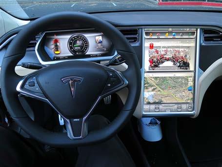
11 Automotive Antennas Antennas are mounted in various locations inside or outside of the vehicle These antennas are highly integrated with the automotive body for aesthetic, practical and performance reasons And they must perform as an integral part of the vehicle


12 Wireless Testing - 2D vs 3D Scan over the major radiation area If the antenna is radiating most power near the horizontal plane, a 2D azimuth cut may be preferred Overall scanning may not be necessary The applications of ETC and Cruise control radar may fall into this category Pattern, Gain, sensitivity, EMC etc. can be evaluated

 FF range and Spherical NF scanner")
13 Wireless Testing - 2D vs 3D If the radio signal propagates more towards the sky - 3D scanning is preferred 3D scanning is over the upper hemisphere Not suitable for long test distance (requires very tall tower and ceiling height ) FF range and Spherical NF scanner can be used
 The number")

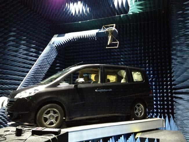
14 Multi Sensor Array Single ring MIMO chamber with multiple sensors (antennas) The number of sensors relative to DuT position define measurement angular resolution Simulated Image
15 OTA Measurements The basic device and components can be measured At bench level for conducted transmit power, throughput, receive sensitivity, etc. The fully assembled module can be measured OTA Pattern, sensitivity, operation and interoperability Measurements can be done on an antenna range Selecting the appropriate range is very important Outdoor far field antenna range (elevated or ground reflection) Indoor far field antenna range Indoor compact range Indoor near field range Courtesy Delphi
16 RADAR Test System Used for RADAR module operation and target recognition testing using target emulation Measure beam width, pattern, transmit power, sensitivity, and target discrimination in the 24GHz, 77GHz and 79GHz bands Approximately 5m x 1.5m x 1.5m test system. Most useful for module level development and production testing Relevant Test standard is EN Top (or side view) Qz Path length 16


17 NSI-MI Solutions Applications: Outdoors Far-Field ranges Spherical Near-Field Ranges Indoors Spherical Near-Field Ranges Free Space and Infinite Ground Quasi-Far-Field Combined Radome protected Spherical Near-Field Outdoor Far-Field add-on
18 Wireless Testing Hybrid FF Range Large tapered chamber, designed for dual purposes, APM and EMC measurement Antenna Pattern Measurement System 2D Long range taper 3D Short range roof scanning 70 MHz to 3 GHz 1GHz to 6 GHz 40 m test distance 9 m test distance

19 FF Antenna Measurement Layout Large tapered chamber, designed for dual purposes, APM and EMC measurement Antenna Pattern Measurement 2D Long range Taper 70 MHz to 3 GHz 40 m test distance 3D Short range Hemisphere 700MHz to 6 GHz 9 m test distance Single or multi-vehicle V2X Performance test 19

20 Hybrid-Chamber Approach Semi-Tapered Far-Field Range for Full-Vehicle Antenna, EMC, ADAS Testing

21 Hybrid-Chamber Approach Semi-Tapered Far-Field Range for Full-Vehicle 2D Measurement Gantry FF/NF range for full vehicle 3D measurement
22 Far-Field vs Near-Field Far-field condition may not be met when the test frequency goes higher and the radiation aperture goes larger. The far-field condition 2D 2 / λ is really the condition when the phase taper reaches to ππ 8. How far is far enough is really a question of the level of measurement accuracy to achieve. For example of a typical radiation patterns for a 30 db Taylor aperture distribution, the shorter ranges cause null filling, even at the 2D 2 / λ distance. Courtesy NSI-MI Technologies 24
23 Far-Field vs Near-Field If we cannot have far enough distance due to the limitation of the available space, nearfield-to-far-field conversion can be applied. NF2FF is nothing more than taking sufficient samples at one wave front in the short range, then re-radiate the sampled wave front (Huygens principle) to the far range. Near Field Z Example 21 Element, 1.0 meter long Phased Array offset 0.7 m diagonally from center of 1.5 m radius test system. Z Far Field NF2FF X Y X Y Courtesy NSI-MI Technologies 25

24 Far-Field vs Near-Field 26 Near Field Reactive near field vs Radiated near field Reactive Near-Field Energy stored as electric (capacitive) or magnetic (inductive) field. rr < 2λis usually a good rule of thumb for half-wave sources rr < 0.62 DD 3 /λ is the generally accepted definition. Radiating Near-Field Primarily propagating RF energy into uniform wave front. Within radiating near-field, patterns are function of distance. r < 2D 2 /λ is the accepted definition. Referred to as the Fresnel region. far Near radiated Near react. Near radiated far Courtesy NSI-MI Technologies


25 Near Field Scanning 27 For a NF2FF system, it is important to sample over the major radiation area, which may again be over the upper hemisphere. There are several NF scanning methods, for example, cylindrical scanning and spherical scanning. Cylindrical scanning is suitable for AUT radiating pattern more confined near the horizontal. Spherical scanning is suitable for AUT pattern radiating more towards the sky (upper hemisphere). Cylindrical Scanning Spherical Scanning
 MRE is used to calculate the measurement angular step needed according to Nyquist (1/2 λ) Low frequency probe")
26 NF- Spherical Sampling Spacing (Steps) The complete vehicle is the AUT Interest : measure the performance of the antenna mounted in the vehicle, not the antenna alone Vehicle body and shape affects the antenna performances Full vehicle size dictates MRE (Maximum Radial Extent of AUT) MRE is used to calculate the measurement angular step needed according to Nyquist (1/2 λ) Low frequency probe vehicle spacing require large scan radium supported by doublesided gantry AUT Size 6.3x2.3x2 m. MRE 3.6 m. FREQ. Nyquist requirement Probe angular step 250 MHz 6 Deg MHz 1.25 Deg MHz 1 Deg MHz 0.8 Deg MHz 0.5 Deg MHz Deg. Courtesy NSI-MI Technologies NF probe Probe/AUT Distance for Near-field - Good: > 3 λ - Usable: > 2 λ - Minimum : > 1 λ (very high mutual coupling) MRE
27 Near Field Scanning 29 For a NF2FF system, the chamber absorber performance is less critical. The probe to QZ distance is typically 2-3 λ, equivalent to less than 2m. Gating can be used to control signals from other reflection boundaries. Installation in existing EMC chambers may be feasible without absorber changes. Most suitable for measurements at frequencies greater than about 800MHz. Not a real time antenna measurement so cannot be used for sensitivity measurements.


28 NF Antenna Measurement Layout Partnership with NSI-MI
, Park")
29 Integrated Solution Support for ADAS feature testing in 10m Chamber ESR RADAR ACC, FCW, AHC, LDW, EAB, Sign recognition, Pedestrian detection (E-NCAP), Park assist
30 Measurement Arch- Pattern Measurement 70MHz to 6GHz ADAS and Communication Testing Controlled Pedestrian/Object Target - AEB RADAR Target Wall Target Simulation Chassis Dyno To Simulate Driving Radar Features - AEB, ACC,FCW Full-sized Chamber For EMC Communication Antennas TIS, TRP
31 FF Antenna Measurement Layout Large tapered chamber, designed for dual purposes, APM and EMC measurement Antenna Pattern Measurement 2D Long range Taper 70 MHz to 3 GHz 40 m test distance 3D Short range Hemisphere 700MHz to 6 GHz 9 m test distance Single or multi-vehicle V2X Performance test 33
32 NF Antenna Measurement Layout Partnership with NSI ETS-Lindgren Confidential
33 Full Vehicle Integrated Range Support for ADAS feature testing in 10m Chamber. ESR RADAR ACC, FCW, AHC, LDW, EAB, Sign recognition, Pedestrian detection (E-NCAP), Park assist. ETS-Lindgren Confidential


34 NSI-MI Automotive Test Solutions Configurations: Single Arm Dual Arm (Gantry) Fixed arch NSI-MI includes: Complete RF Subsystem Project Management Advanced Antenna Measurements Software


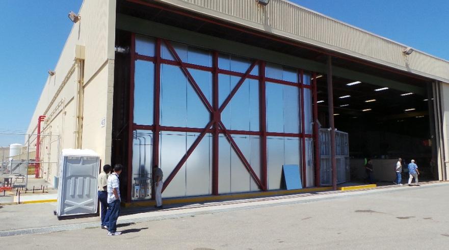
35 ETS-Lindgren / NSI Team Capabilities RF-Shielded Anechoic Chamber

36 NSI-MI Retractable Design High Precision Spherical NF Single arm 3-Axis: Turntable, gantry arm and polarization 1.7m vertical arm adjustment Arm storage capability to allow other type of testing 7m. Turntable, 6000 Kg with RJ, SR Controller Complete RF Subsystem Receiver, Sources, mixers, switches Probes and reference antennas Advanced antenna measurements Software
 Probe to MRE distance= 200 cm λ (450MHz) = 66 cm Optimal NF test distance= >3λ @450MHz -> 3λ=199 cm Testing below 450MHz is possible")
37 NSI-MI Retractable Design 5.6 m probe to Turntable Higher elevating the Arm axis Optimal distance for >450 MHz testing Vehicle: 6.3x2.3x2 m. MRE=3.6m (reduced with smaller vehicles) Probe to MRE distance= 200 cm λ (450MHz) = 66 cm Optimal NF test distance= -> 3λ=199 cm Testing below 450MHz is possible with increased uncertainty


38 Block Diagram Note: a rotary joint and a polarization stage may be needed if single linear polarized probes are used Switch control from MI manual switch DC-50GHz Antenna on vehicle MI-789 Auxiliary Controller RANGE SIGNAL CHANNEL Elevation (Gantry) Azimuth (TT) E5072A ENA MI trigger bus MI-350-TA Trigger Bus Adapter MI-710C Position Controller CONTROL ROOM MI-3003 WORKSTATION WITH MI-3000 ARENA TM & MI-3046 SNF ENET SWITCH
 to get the best performance where")

39 5G Adaptive Beam Forming 5G adds another level of measurement complexity Beamforming / Beam steering / Null steering technology Uses actively Adaptive Antenna System (AAS) to get the best performance where needed or alternatively deepest null to filter out the interferers in real time Vary the performance of array algorithm and throughput Perform Array Pattern, and sensitivity measurement Patents Pending 41
40 Conclusions The industry is moving rapidly Already available Radio connectivity Autonomous cruise control, steering, breaking Navigation Collision avoidance Blind spot warning Integrated infotainment BYOD support Apple, Google In development Fully Autonomous capability
41 Conclusions Autonomous Cruise Control Already available Also known as adaptive or radar cruise control Automatically adjusts vehicle speed to maintain a safe distance from vehicles ahead Control based solely on on board sensors Uses no communication with satellite or roadside infrastructure 77GHz Auto cruise system available Has a forward range of up to 492 ft (150m) Operates at vehicle speeds ranging from 18.6mph (30kph) to 111mph (180kph)
42 Conclusions New test facilities have already begun to appear designed to support EMC Wireless OTA and interoperability Antenna measurements The demands on absorber design is more important Interoperability for wireless in EM environment With optimized chamber performance, and customized layout, the requirements for the EMC and APM chamber can both be met
HOW TO CHOOSE AN ANTENNA RANGE CONFIGURATION
 HOW TO CHOOSE AN ANTENNA RANGE CONFIGURATION Donnie Gray Nearfield Systems, Inc. 1330 E. 223 rd St, Bldg 524 Carson, CA 90745 (310) 518-4277 dgray@nearfield.com Abstract Choosing the proper antenna range
ADVANTAGES AND DISADVANTAGES OF VARIOUS HEMISPHERICAL SCANNING TECHNIQUES
 ADVANTAGES AND DISADVANTAGES OF VARIOUS HEMISPHERICAL SCANNING TECHNIQUES Eric Kim & Anil Tellakula MI Technologies Suwanee, GA, USA ekim@mitechnologies.com Abstract - When performing far-field or near-field
Millimeter Spherical µ-lab System from Orbit/FR
 Millimeter Spherical µ-lab System from Orbit/FR Jim Puri Sr. Applications Engineer Orbit/FR, Inc. a Microwave Vision Group company Keysight Technologies and MVG Orbit/FR Partners in Radiated Measurement
Specification of Requirements. Request for tenders for antenna systems for Aalborg University. Side 1
 Specification of Requirements Request for tenders for antenna systems for Aalborg University Side 1 1. Introduction The Department of Electronic Systems represents one of the areas of research of Aalborg
A CYLINDRICAL NEAR-FIELD VS. SPHERICAL NEAR-FIELD ANTENNA TEST COMPARISON
 A CYLINDRICAL NEAR-FIELD VS. SPHERICAL NEAR-FIELD ANTENNA TEST COMPARISON Jeffrey Fordham VP, Sales and Marketing MI Technologies, 4500 River Green Parkway, Suite 200 Duluth, GA 30096 jfordham@mi-technologies.com
Fundamentals. Senior Project Manager / AEO Taiwan. Philip Chang
 mmwave OTA Fundamentals Senior Project Manager / AEO Taiwan Philip Chang L A R G E LY D R I V E N B Y N E W W I R E L E S S T E C H N O L O G I E S A N D F R E Q U E N C Y B A N D S 1. Highly integrated
System configurations. Main features I SG 64 SOLUTION FOR
 T- DualScan SG 64 The most accurate solution for testing antennas and wireless devices: SG 64 has been developed to measure stand alone antennas or antennas integrated in subsystems. It is also ideal for
System configurations. Main features. I TScan SOLUTION FOR
 TScan TScan is a fast and ultra-accurate planar near-field scanner with the latest motor drive and encoder technologies. High acceleration of the linear motors for stepped and continuous mode operation
RAYTHEON 23 x 22 50GHZ PULSE SYSTEM
 RAYTHEON 23 x 22 50GHZ PULSE SYSTEM Terry Speicher Nearfield Systems, Incorporated 1330 E. 223 rd Street, Bldg. 524 Carson, CA 90745 www.nearfield.com Angelo Puzella and Joseph K. Mulcahey Raytheon Electronic
Software. Equipment. Add-ons. Accessories. Services
 T- DualScan FScan FScan is a vertical near-field planar scanner system that is a perfect solution for antenna measurement applications where a phased array, high gain, or reflector antenna is under evaluation.
T- DualScan. StarLab
 T- DualScan StarLab StarLab is the ultimate tool for antenna pattern measurements in laboratories and production environments where space is limited, cost is critical, and the flexibility of a portable
Rapid Antenna Measurement Systems
 Rapid Antenna Measurement Systems They are essentially multi probe, electronically scanned, near field measurement systems. The characterization of the antenna is accomplished very fast and accurately
Main features. System configurations. I Compact Range SOLUTION FOR
 Compact Range + Direct far-field measurement of electrically large antennas SOLUTION FOR Antenna measurement Radome measurement RCS measurement A Compact Range makes direct far-field measurement of electrically
Conventional measurement systems
 Conventional measurement systems NEAR FIELD Near-field measurement is suitable for a variety of antennas, from small antennas in compact electronic devices to very large phased array antennas. Planar near-field
5G ANTENNA TEST AND MEASUREMENT SYSTEMS OVERVIEW
 5G ANTENNA TEST AND MEASUREMENT SYSTEMS OVERVIEW MVG, AT THE FOREFRONT OF 5G WIRELESS CONNECTIVITY! VISION The connected society enabled by 5G Smart cities Internet of Things 5G lays the foundation for
A COMPOSITE NEAR-FIELD SCANNING ANTENNA RANGE FOR MILLIMETER-WAVE BANDS
 A COMPOSITE NEAR-FIELD SCANNING ANTENNA RANGE FOR MILLIMETER-WAVE BANDS Doren W. Hess dhess@mi-technologies.com John McKenna jmckenna@mi-technologies.com MI-Technologies 1125 Satellite Boulevard Suite
> StarLab. Multi-purpose Antenna Measurement Multi-protocol Antenna Development Linear Array Antenna Measurement OTA Testing
 TECHNOLOGY Near-field / Spherical Near-field / Cylindrical SOLUTIONS FOR Multi-purpose Antenna Measurement Multi-protocol Antenna Development Linear Array Antenna Measurement OTA Testing 18 StarLab: a
The LACE Antenna Test Ranges
 Politecnico di Torino The LACE Antenna Test Ranges 1. Introduction Politecnico di Torino is the oldest Technical University in Italy, with more than one and a half centuries of academic activity. It is
5G The overall test challenge from system to device 5G NR T&M aspects
 5G The overall test challenge from system to device 5G NR T&M aspects embb Reiner Stuhlfauth Technology Manager Wireless Rohde & Schwarz miot / mmtc URLLC Optimizing the present. Designing the future.
Physically and Electrically Large Antennas for Antenna Pattern Measurements and Radar Cross Section Measurements in the Upper VHF and UHF bands
 Physically and Electrically Large Antennas for Antenna Pattern Measurements and Radar Cross Section Measurements in the Upper VHF and UHF bands Vince Rodriguez, PhD Product Manager, Antennas ETS-Lindgren,
A TECHNIQUE TO EVALUATE THE IMPACT OF FLEX CABLE PHASE INSTABILITY ON mm-wave PLANAR NEAR-FIELD MEASUREMENT ACCURACIES
 A TECHNIQUE TO EVALUATE THE IMPACT OF FLEX CABLE PHASE INSTABILITY ON mm-wave PLANAR NEAR-FIELD MEASUREMENT ACCURACIES Daniël Janse van Rensburg Nearfield Systems Inc., 133 E, 223rd Street, Bldg. 524,
Accurate Planar Near-Field Results Without Full Anechoic Chamber
 Accurate Planar Near-Field Results Without Full Anechoic Chamber Greg Hindman, Stuart Gregson, Allen Newell Nearfield Systems Inc. Torrance, CA, USA ghindman@nearfield.com Abstract - Planar near-field
White paper on CAR150 millimeter wave radar
 White paper on CAR150 millimeter wave radar Hunan Nanoradar Science and Technology Co.,Ltd. Version history Date Version Version description 2017-02-23 1.0 The 1 st version of white paper on CAR150 Contents
Massive MIMO prototype and mmw OTA Test challenge
 Massive MIMO prototype and mmw OTA Test challenge Philip Chang Senior Project Manager July, 2017 5G Market direction Expected timeline 2016 2017 2018 2019 2020 Pre-3GPP specifications Pre-commercial trials
ANECHOIC CHAMBER DIAGNOSTIC IMAGING
 ANECHOIC CHAMBER DIAGNOSTIC IMAGING Greg Hindman Dan Slater Nearfield Systems Incorporated 1330 E. 223rd St. #524 Carson, CA 90745 USA (310) 518-4277 Abstract Traditional techniques for evaluating the
IMPROVING AND EXTENDING THE MARS TECHNIQUE TO REDUCE SCATTERING ERRORS
 IMPROVING AND EXTENDING THE MARS TECHNIQUE TO REDUCE SCATTERING ERRORS Greg Hindman & Allen C. Newell Nearfield Systems Inc. 1973 Magellan Drive Torrance, CA 952 ABSTRACT The Mathematical Absorber Reflection
LUXONDES. See the electromagnetic waves. Product 2018 / 19
 LUXONDES See the electromagnetic waves Product 2018 / 19 RADIO WAVES DISPLAY - 400 The Luxondes radiofrequency to optical conversion panel directly displays the ambient EM-field or the radiation of a transmitting
SPHERICAL NEAR-FIELD MEASUREMENTS AT UHF FREQUENCIES WITH COMPLETE UNCERTAINTY ANALYSIS
 SPHERICAL NEAR-FIELD MEASUREMENTS AT UHF FREQUENCIES WITH COMPLETE UNCERTAINTY ANALYSIS Allen Newell, Patrick Pelland Nearfield Systems Inc. 19730 Magellan Drive, Torrance, CA 90502-1104 Brian Park, Ted
Millimetre Spherical Wave Antenna Pattern Measurements at NPL. Philip Miller May 2009
 Millimetre Spherical Wave Antenna Pattern Measurements at NPL Philip Miller May 2009 The NPL Spherical Range The NPL Spherical Range is a conventional spherical range housed within a 15 m by 7.5 m by 7.5
Very-Near-Field Solutions for Antenna Measurement Problems
 Very-Near-Field Solutions for Antenna Measurement Problems Chamber on your Desktop EMxpert EMC diagnostic tool to rapidly diagnose and solve EMC/EMS/EMI problems with real-time PCB emission analysis RFxpert
A LARGE COMBINATION HORIZONTAL AND VERTICAL NEAR FIELD MEASUREMENT FACILITY FOR SATELLITE ANTENNA CHARACTERIZATION
 A LARGE COMBINATION HORIZONTAL AND VERTICAL NEAR FIELD MEASUREMENT FACILITY FOR SATELLITE ANTENNA CHARACTERIZATION John Demas Nearfield Systems Inc. 1330 E. 223rd Street Bldg. 524 Carson, CA 90745 USA
Millimeter Wave Measurement System
 Millimeter Wave Measurement System Testing Existing and Upcoming Technologies FREQUENCY RANGE Supports Millimeter Wave Frequencies and Bandwidths 18 to 26.5 GHz 26.5 to 40 GHz 33 to 50 GHz 40 to 60 GHz
ALIGNMENT SENSITIVITY AND CORRECTION METHODS FOR MILLIMETER- WAVE SPHERICAL NEAR-FIELD MEASUREMENTS
 ALIGNMENT SENSITIVITY AND CORRECTION METHODS FOR MILLIMETER- WAVE SPHERICAL NEAR-FIELD MEASUREMENTS Greg Hindman, Allen Newell Nearfield Systems Inc. 1973 Magellan Drive Torrance, CA 952, USA Luciano Dicecca
Vehicle-to-X communication using millimeter waves
 Infrastructure Person Vehicle 5G Slides Robert W. Heath Jr. (2016) Vehicle-to-X communication using millimeter waves Professor Robert W. Heath Jr., PhD, PE mmwave Wireless Networking and Communications
Large E Field Generators in Semi-anechoic Chambers for Full Vehicle Immunity Testing
 Large E Field Generators in Semi-anechoic Chambers for Full Vehicle Immunity Testing Vince Rodriguez ETS-Lindgren, Inc. Abstract Several standards recommend the use of transmission line systems (TLS) as
Model 3140B BiConiLog Antenna User Manual
 Model 3140B BiConiLog Antenna User Manual Model 3140B mounted onto a 7-TR tripod (not included) ETS-Lindgren L.P. reserves the right to make changes to any product described herein in order to improve
APPLICATIONS OF PORTABLE NEAR-FIELD ANTENNA MEASUREMENT SYSTEMS
 APPLICATIONS OF PORTABLE NEAR-FIELD ANTENNA MEASUREMENT SYSTEMS Greg Hindman Nearfield Systems Inc. 1330 E. 223rd Street Bldg. 524 Carson, CA 90745 (213) 518-4277 ABSTRACT Portable near-field measurement
From myth to reality - Leading the industry from conducted to radiated testing for 5G mmwave
 From myth to reality - Leading the industry from conducted to radiated testing for 5G mmwave Alexander Pabst Vice President Systems & Projects Test & Measurement Division COM PANY RESTRICTED Why 5G?: Capacity
REFLECTION SUPPRESSION IN LARGE SPHERICAL NEAR-FIELD RANGE
 REFLECTION SUPPRESSION IN LARGE SPHERICAL NEAR-FIELD RANGE Greg Hindman & Allen C. Newell Nearfield Systems Inc. 1973 Magellan Drive Torrance, CA 952 ABSTRACT Reflections in antenna test ranges can often
Accuracy Estimation of Microwave Holography from Planar Near-Field Measurements
 Accuracy Estimation of Microwave Holography from Planar Near-Field Measurements Christopher A. Rose Microwave Instrumentation Technologies River Green Parkway, Suite Duluth, GA 9 Abstract Microwave holography
Automotive 77GHz; Coupled 3D-EM / Asymptotic Simulations. Franz Hirtenfelder CST /AG
 Automotive Radar @ 77GHz; Coupled 3D-EM / Asymptotic Simulations Franz Hirtenfelder CST /AG Abstract Active safety systems play a major role in reducing traffic fatalities, including adaptive cruise control,
Absorbers and Anechoic Chamber Measurements
 Absorbers and Anechoic Chamber Measurements Zhong Chen Director, RF Engineering ETS-Lindgren 1301 Arrow Point Dr. Cedar Park, TX, 78613 Zhong.chen@ets-lindgren.com SUMMARY Absorber Overview Absorber Materials
Model BiConiLog Antenna. User Manual
 Model 3149 BiConiLog Antenna User Manual ETS-Lindgren Inc. reserves the right to make changes to any products herein to improve functioning or design. Although the information in this document has been
EMC ANECHOIC CHAMBERS 5-METER CHAMBERS
 ETS-Lindgren's FACT 5 Chambers offer semi-anechoic radiated emissions (RE) and fully anechoic radiated immunity (RI) compliance test capability for most international EMC compliance regulations. FACT 5
33 BY 16 NEAR-FIELD MEASUREMENT SYSTEM
 33 BY 16 NEAR-FIELD MEASUREMENT SYSTEM ABSTRACT Nearfield Systems Inc. (NSI) has delivered the world s largest vertical near-field measurement system. With a 30m by 16m scan area and a frequency range
Absorbers and Anechoic Chamber Measurements
 Absorbers and Anechoic Chamber Measurements Zhong Chen Director, RF Engineering ETS-Lindgren 1301 Arrow Point Dr. Cedar Park, TX, 78613 Zhong.chen@ets-lindgren.com SUMMARY Absorber Overviews Absorber Materials
Non-Ideal Quiet Zone Effects on Compact Range Measurements
 Non-Ideal Quiet Zone Effects on Compact Range Measurements David Wayne, Jeffrey A. Fordham, John McKenna MI Technologies Suwanee, Georgia, USA Abstract Performance requirements for compact ranges are typically
ME7220A. Radar Test System (RTS) Target Simulation & Signal Analysis for Automotive Radar Exceptional Performance at an Affordable Price.
 Target Simulation & Signal Analysis for Automotive Radar Exceptional Performance at an Affordable Price.") ME7220A Test System (RTS) 76 to 77 GHz Target Simulation & Signal Analysis for Automotive Exceptional Performance at an Affordable Price The Challenge The installation of collision warning and Adaptive
ME7220A Test System (RTS) 76 to 77 GHz Target Simulation & Signal Analysis for Automotive Exceptional Performance at an Affordable Price The Challenge The installation of collision warning and Adaptive
REVERBERATION CHAMBER FOR EMI TESTING
 1 REVERBERATION CHAMBER FOR EMI TESTING INTRODUCTION EMI Testing 1. Whether a product is intended for military, industrial, commercial or residential use, while it must perform its intended function in
A Method for Gain over Temperature Measurements Using Two Hot Noise Sources
 A Method for Gain over Temperature Measurements Using Two Hot Noise Sources Vince Rodriguez and Charles Osborne MI Technologies: Suwanee, 30024 GA, USA vrodriguez@mitechnologies.com Abstract P Gain over
Cobham Antenna Systems
 Cobham Antenna Systems Microwave Antennas Dual-Polar MIMO Base Station Antennas The most important thing we build is trust Compact, lightweight and rugged antennas High data throughput with minimised dropout
Systems characteristics of automotive radars operating in the frequency band GHz for intelligent transport systems applications
 Recommendation ITU-R M.257-1 (1/218) Systems characteristics of automotive s operating in the frequency band 76-81 GHz for intelligent transport systems applications M Series Mobile, radiodetermination,
Antenna Measurement Theory
 Introduction to Antenna Measurement 1. Basic Concepts 1.1 ELECTROMAGNETIC WAVES The radiation field from a transmitting antenna is characterized by the complex Poynting vector E x H* in which E is the
Visione per il veicolo Paolo Medici 2017/ Visual Perception
 Visione per il veicolo Paolo Medici 2017/2018 02 Visual Perception Today Sensor Suite for Autonomous Vehicle ADAS Hardware for ADAS Sensor Suite Which sensor do you know? Which sensor suite for Which algorithms
Further Refining and Validation of RF Absorber Approximation Equations for Anechoic Chamber Predictions
 Further Refining and Validation of RF Absorber Approximation Equations for Anechoic Chamber Predictions Vince Rodriguez, NSI-MI Technologies, Suwanee, Georgia, USA, vrodriguez@nsi-mi.com Abstract Indoor
NTT DOCOMO Technical Journal. Method for Measuring Base Station Antenna Radiation Characteristics in Anechoic Chamber. 1.
 Base Station Antenna Directivity Gain Method for Measuring Base Station Antenna Radiation Characteristics in Anechoic Chamber Base station antennas tend to be long compared to the wavelengths at which
Using Frequency Diversity to Improve Measurement Speed Roger Dygert MI Technologies, 1125 Satellite Blvd., Suite 100 Suwanee, GA 30024
 Using Frequency Diversity to Improve Measurement Speed Roger Dygert MI Technologies, 1125 Satellite Blvd., Suite 1 Suwanee, GA 324 ABSTRACT Conventional antenna measurement systems use a multiplexer or
GAIN COMPARISON MEASUREMENTS IN SPHERICAL NEAR-FIELD SCANNING
 GAIN COMPARISON MEASUREMENTS IN SPHERICAL NEAR-FIELD SCANNING ABSTRACT by Doren W. Hess and John R. Jones Scientific-Atlanta, Inc. A set of near-field measurements has been performed by combining the methods
5G Antenna System Characteristics and Integration in Mobile Devices Sub 6 GHz and Milli-meter Wave Design Issues
 5G Antenna System Characteristics and Integration in Mobile Devices Sub 6 GHz and Milli-meter Wave Design Issues November 2017 About Ethertronics Leader in advanced antenna system technology and products
HScan. Horizontal Scanner
 HScan Horizontal Scanner HScan is a fast and ultra-accurate horizontal near-field planar scanner particularly suited for the antenna measurement of space-borne antennas, large reflectors and certain vehicle
Enabling autonomous driving
 Automotive fuyu liu / Shutterstock.com Enabling autonomous driving Autonomous vehicles see the world through sensors. The entire concept rests on their reliability. But the ability of a radar sensor to
This article reports on
 Millimeter-Wave FMCW Radar Transceiver/Antenna for Automotive Applications A summary of the design and performance of a 77 GHz radar unit David D. Li, Sam C. Luo and Robert M. Knox Epsilon Lambda Electronics
Part No. ETH-MMW-1000 (version 1A) Millimeter Measurement System Frequency Range: 18 GHz 75 GHz
 Millimeter Measurement System Frequency Range: 18 GHz 75 GHz") DATASHEET (v1.5) Part No: ETH-MMW-1000 (version 1A) Product: Millimeter Measurement System Part No. ETH-MMW-1000 (version 1A) Millimeter Measurement System Frequency Range: 18 GHz 75 GHz Ethertronics presents
DATASHEET (v1.5) Part No: ETH-MMW-1000 (version 1A) Product: Millimeter Measurement System Part No. ETH-MMW-1000 (version 1A) Millimeter Measurement System Frequency Range: 18 GHz 75 GHz Ethertronics presents
Log Periodic Dipole Array Antenna
 Model 3148B Log Periodic Dipole Array Antenna User Manual ETS-Lindgren L.P. reserves the right to make changes to any product described herein in order to improve function, design, or for any other reason.
Range Considerations for RF Networks
 TI Technology Days 2010 Range Considerations for RF Networks Richard Wallace Abstract The antenna can be one of the most daunting components of wireless designs. Most information available relates to large
INDOOR AUTOMATIC F-16 FIRE CONTROL ANTENNA AND RADOME TEST FACILITIES
 INDOOR AUTOMATIC F-16 FIRE CONTROL ANTENNA AND RADOME TEST FACILITIES ABSTRACT by Joseph J. Anderson MI Technologies was selected by the United States Air Force to design and install a complete turn-key
Structural Correction of a Spherical Near-Field Scanner for mm-wave Applications
 Structural Correction of a Spherical Near-Field Scanner for mm-wave Applications Daniël Janse van Rensburg & Pieter Betjes Nearfield Systems Inc. 19730 Magellan Drive Torrance, CA 90502-1104, USA Abstract
Model 3180B Mini-Bicon Antenna User Manual
 Model 3180B Mini-Bicon Antenna User Manual Model 3180B with conical elements Model 3180B with cage elements ETS-Lindgren L.P. reserves the right to make changes to any product described herein in order
Development of a noval Switched Beam Antenna for Communications
 Master Thesis Presentation Development of a noval Switched Beam Antenna for Communications By Ashraf Abuelhaija Supervised by Prof. Dr.-Ing. Klaus Solbach Institute of Microwave and RF Technology Department
The Future Autonomous Driving Techniques and Test Challenges. Sr. Project Manager / Keysight Technologies
 The Future Autonomous Driving Techniques and Test Challenges Sr. Project Manager / Keysight Technologies Brian Su 2018.06.11 Taipei 2 3 Autonomous Driving & e-mobility Data Source: WHO, US EPA 4 Traffic
Estimating Measurement Uncertainties in Compact Range Antenna Measurements
 Estimating Measurement Uncertainties in Compact Range Antenna Measurements Stephen Blalock & Jeffrey A. Fordham MI Technologies Suwanee, Georgia, USA sblalock@mitechnologies.com jfordham@mitechnolgies.com
Principles of Planar Near-Field Antenna Measurements. Stuart Gregson, John McCormick and Clive Parini. The Institution of Engineering and Technology
 Principles of Planar Near-Field Antenna Measurements Stuart Gregson, John McCormick and Clive Parini The Institution of Engineering and Technology Contents Preface xi 1 Introduction 1 1.1 The phenomena
Using measured fields as field sources in computational electromagnetic (CEM) solvers
 solvers") Using measured fields as field sources in computational electromagnetic (CEM) solvers Presenter: Lucia Scialacqua lucia.scialacqua@microwavevision.com Content Domain decomposition techniques have been
Using measured fields as field sources in computational electromagnetic (CEM) solvers Presenter: Lucia Scialacqua lucia.scialacqua@microwavevision.com Content Domain decomposition techniques have been
A TURNKEY NEAR-FIELD MEASUREMENT SYSTEM FOR PULSE MODE APPLICATIONS
 A TURNKEY NEAR-FIELD MEASUREMENT SYSTEM FOR PULSE MODE APPLICATIONS David S. Fooshe 1, Kenneth Thompson 2, Matt Harvey 3 1 Nearfield Systems Inc. 1330 E. 223rd Street Bldg 524 Carson, CA 90745 USA (310)
Near-Field Antenna Measurements using a Lithium Niobate Photonic Probe
 Near-Field Antenna Measurements using a Lithium Niobate Photonic Probe Vince Rodriguez 1, Brett Walkenhorst 1, and Jim Toney 2 1 NSI-MI Technologies, Suwanee, Georgia, USA, Vrodriguez@nsi-mi.com 2 Srico,
Positioning Challenges in Cooperative Vehicular Safety Systems
 Positioning Challenges in Cooperative Vehicular Safety Systems Dr. Luca Delgrossi Mercedes-Benz Research & Development North America, Inc. October 15, 2009 Positioning for Automotive Navigation Personal
Antennas & Measurement of its parameters
 Antennas & Measurement of its parameters Chandana Viswanadham SDGM (D&E), Bharat Electronics, IE, Nacharam, Hyderabad 500 076 ABSTRACT As all of us aware, a communication system comprises Transmitter,
Antenna Measurement Uncertainty Method for Measurements in Compact Antenna Test Ranges
 Antenna Measurement Uncertainty Method for Measurements in Compact Antenna Test Ranges Stephen Blalock & Jeffrey A. Fordham MI Technologies Suwanee, Georgia, USA Abstract Methods for determining the uncertainty
Keywords: cylindrical near-field acquisition, mechanical and electrical errors, uncertainty, directivity.
 UNCERTAINTY EVALUATION THROUGH SIMULATIONS OF VIRTUAL ACQUISITIONS MODIFIED WITH MECHANICAL AND ELECTRICAL ERRORS IN A CYLINDRICAL NEAR-FIELD ANTENNA MEASUREMENT SYSTEM S. Burgos, M. Sierra-Castañer, F.
Dr. John S. Seybold. November 9, IEEE Melbourne COM/SP AP/MTT Chapters
 Antennas Dr. John S. Seybold November 9, 004 IEEE Melbourne COM/SP AP/MTT Chapters Introduction The antenna is the air interface of a communication system An antenna is an electrical conductor or system
GPS/GNSS Antennas. В. Rama Rao W. Kunysz R. Fante К. McDonald ARTECH HOUSE. BOSTON LONDON artechhouse.com
 GPS/GNSS Antennas В. Rama Rao W. Kunysz R. Fante К. McDonald ARTECH HOUSE BOSTON LONDON artechhouse.com Contents Preface xv CHAPTER 1 Introduction to GNSS Antenna Performance Parameters 1 1.1 Role of an
4GHz / 6GHz Radiation Measurement System
 4GHz / 6GHz Radiation Measurement System The MegiQ Radiation Measurement System (RMS) is a compact test system that performs 3-axis radiation pattern measurement in non-anechoic spaces. With a frequency
Over the Air Testing: Important Antenna Parameters, Testing Methodologies and Standards
 Over the Air Testing: Important Antenna Parameters, Testing Methodologies and Standards Alexander Naehring Rohde & Schwarz GmbH & Co. KG Muehldorfstr. 15, 81671 Munich, Germany Email: alexander.naehring@rohde-schwarz.com
Upgraded Planar Near-Field Test Range For Large Space Flight Reflector Antennas Testing from L to Ku-Band
 Upgraded Planar Near-Field Test Range For Large Space Flight Reflector Antennas Testing from L to Ku-Band Laurent Roux, Frédéric Viguier, Christian Feat ALCATEL SPACE, Space Antenna Products Line 26 avenue
E MC Ane c hoi c Chambers
 E MC Ane c hoi c Chambers.)+6! Features 6 MHz - 8 GHz Frequency Range Full Compliance Testing for Radiated Emissions: - ANSI C6. Parts 5 & 8 - EN 57 - CISPR / EN55 - CISPR 6/ EN556 - CISPR / EN55 - VCCI
Characterization of a Photonics E-Field Sensor as a Near-Field Probe
 Characterization of a Photonics E-Field Sensor as a Near-Field Probe Brett T. Walkenhorst 1, Vince Rodriguez 1, and James Toney 2 1 NSI-MI Technologies Suwanee, GA 30024 2 SRICO Columbus, OH 43235 bwalkenhorst@nsi-mi.com
HyperLink Wireless High Density 2.4/5 GHz Four Element Dual Polarized Flat Panel Antenna Model: HG HDP-4NF
 HyperLink Wireless High Density 2.4/5 GHz Four Element Dual Polarized Flat Panel Antenna Model: HG2458-13HDP-4NF Features Four independent antennas, two vertical and two horizontal Narrow beamwidth for
An introduction to Mobile Station Over-the-Air measurements
 An introduction to Mobile Station Over-the-Air measurements Gregory F. Masters. Nearfield Systems Inc. 19730 Magellan Drive Torrance, CA 90502 ABSTRACT Active antenna measurements are familiar to traditional
PERFORMANCE CONSIDERATIONS FOR PULSED ANTENNA MEASUREMENTS
 PERFORMANCE CONSIDERATIONS FOR PULSED ANTENNA MEASUREMENTS David S. Fooshe Nearfield Systems Inc., 19730 Magellan Drive Torrance, CA 90502 USA ABSTRACT Previous AMTA papers have discussed pulsed antenna
Todd Hubing. Clemson University. Cabin Environment Communication System. Controls Airbag Entertainment Systems Deployment
 Automotive Component Measurements for Determining Vehicle-Level Radiated Emissions Todd Hubing Michelin Professor of Vehicular Electronics Clemson University Automobiles are Complex Electronic Systems
A LARGE SPHERICAL NEAR-FIELD ARCH SCANNER FOR CHARACTERIZING LOW-FREQUENCY PHASED ARRAYS
 A LARGE SPHERICAL NEAR-FIELD ARCH SCANNER FOR CHARACTERIZING LOW-FREQUENCY PHASED ARRAYS Scott McBride (1), Jeffrey P. Marier (2), Charles J. Kryzak (2), Jeffrey Fordham (1), Kefeng Liu (3) SMcBride@mi-technologies.com
Test and Measurement for EMC
 Test and Measurement for EMC Bogdan Adamczyk, Ph.D., in.c.e. Professor of Engineering Director of the Electromagnetic Compatibility Center Grand Valley State University, Michigan, USA Ottawa, Canada July
Semi Anechoic Chamber (SAC)
") 1 of 9 Semi Anechoic Chamber (SAC) Approximate Dimensions of 3m Semi Anechoic Chamber (SAC) Length: 10m Width: 9m Height: 9m Frequency range of Semi Anechoic Chamber: 9 KHz to 40 GHz Emission test (EMI):
1 of 9 Semi Anechoic Chamber (SAC) Approximate Dimensions of 3m Semi Anechoic Chamber (SAC) Length: 10m Width: 9m Height: 9m Frequency range of Semi Anechoic Chamber: 9 KHz to 40 GHz Emission test (EMI):
Sub-millimeter Wave Planar Near-field Antenna Testing
 Sub-millimeter Wave Planar Near-field Antenna Testing Daniёl Janse van Rensburg 1, Greg Hindman 2 # Nearfield Systems Inc, 1973 Magellan Drive, Torrance, CA, 952-114, USA 1 drensburg@nearfield.com 2 ghindman@nearfield.com
Introduction Antenna Ranges Radiation Patterns Gain Measurements Directivity Measurements Impedance Measurements Polarization Measurements Scale
 Chapter 17 : Antenna Measurement Introduction Antenna Ranges Radiation Patterns Gain Measurements Directivity Measurements Impedance Measurements Polarization Measurements Scale Model Measurements 1 Introduction
MISSION TO MARS - IN SEARCH OF ANTENNA PATTERN CRATERS
 MISSION TO MARS - IN SEARCH OF ANTENNA PATTERN CRATERS Greg Hindman & Allen C. Newell Nearfield Systems Inc. 197 Magellan Drive Torrance, CA 92 ABSTRACT Reflections in anechoic chambers can limit the performance
SAC-10 Plus Triton Class
 Anechoic Chamber SAC-10 Plus Triton Class SAC-10 Plus Triton Class Frankonia s anechoic chamber for 10.0 & 3.0 m measuring distance with triple test axes FRANKONIA CONCEPT SAC-10 Plus Triton Class Frankonia
Evaluation of Connected Vehicle Technology for Concept Proposal Using V2X Testbed
 AUTOMOTIVE Evaluation of Connected Vehicle Technology for Concept Proposal Using V2X Testbed Yoshiaki HAYASHI*, Izumi MEMEZAWA, Takuji KANTOU, Shingo OHASHI, and Koichi TAKAYAMA ----------------------------------------------------------------------------------------------------------------------------------------------------------------------------------------------------------------------------------------------------------
Realistic testing of operational radio. virtual electromagnetic environments
 Realistic testing of operational radio communications from and to vehicles in virtual electromagnetic environments Over-The-Air in a Virtual Electromagnetic Environment Wim Kotterman, Markus Landmann,
Vehicle-to-X communication for 5G - a killer application of millimeter wave
 2017, Robert W. W. Heath Jr. Jr. Vehicle-to-X communication for 5G - a killer application of millimeter wave Professor Robert W. Heath Jr. Wireless Networking and Communications Group Department of Electrical