Digital Leakage Today
|
|
|
- Oswald Craig
- 6 years ago
- Views:
Transcription
1 Digital Leakage Today Analog and Digital Leakage LTE interference Kendall Robinson Regional Account Director Arcom Digital
2 Digital Leakage Outline Digital Leakage Traditional Leakage LTE Ingress and Egress issues QAM Snare overview Analysis of results at 3 leakage demo trials
3
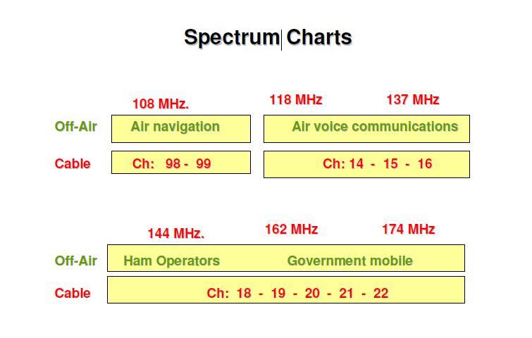
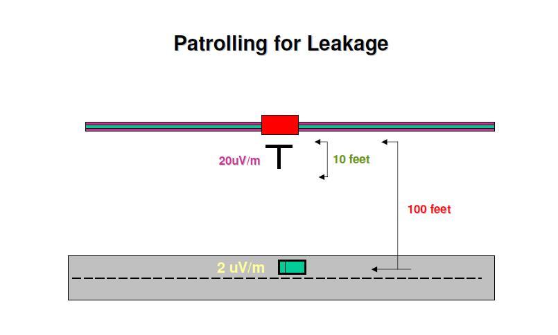
4 Traditional Signal Leakage Today Most legacy leakage systems are in the aeronautical band from 108 to 137MHz A common frequency is MHz (Visual CEA channel) Max allowed signal strength at 10 feet is 20uV/m Many operators target to fix all leaks greater than 10uV/m Some fix above 5uVm A few have a goal to fix any size leak on their system
5 Signal Leakage Regulations Signal leakage regulations in Part 76 of the FCC s Rules. The following table, taken from (a)(12), states the maximum allowable signal leakage field strengths across various frequency ranges: Frequencies Signal leakage limit in microvolt per meter (uv/m) Distance in feet (f) Distance in meters (m) Less than 15 ~ MHz 54MHz to 20 ~ MHz Over 216 MHz 15 ~100 30
6
7 Signal Leakage Regulations Distance at 10 feet is 20uV/m larger Frequencies Signal leakage limit in microvolt per meter (uv/m) Distance in feet (f) Distance in meters (m) Over 216 MHz 15 ~ Over 216 MHz 150 ~10 3
8 LTE Overview LTE means (Long Term Evolution) Downlink: OFDM - (QPSK, 16QAM and 64QAM) Uplink: SC-FDMA (QPSK and 16QAM) Paired Duplex: FDD (Frequency-division duplex) paired downlink and uplink Bandwidth: 5 and 10MHz (typical in the US)
9 Orthogonal Frequency Division Multiplexing OFDM is a broadband multicarrier modulation method that offers superior performance and benefits over older, more traditional single-carrier modulation methods because it is a better fit with today s high-speed data requirements and operation in the UHF and microwave spectrum.
10 What makes LTE different to Traditional Cell technology? LTE in the USA is in the MHz band which falls in the CATV frequency band Compare to traditional cell (CDMS and GSM) at 1.8GHz, 1.9GHz and 2.1GHz. LTE is of particular concern for Cable systems with 750 MHz, 850 MHz and 1 GHZ systems. Signals in the 700 MHz band (compared to traditional cell signals) travel further and are less attenuated by structures. OFDM in the downlink side has a higher potential power spectral density than traditional cell signals. (These change) When there are fewer resource blocks and the total signal power is divided among fewer subscribers. There is a higher probability of ingress as the energy is concentrated to a smaller allocated bandwidth. Especially an issue in the LTE uplink.
11 LTE bandwidth and frequency allocation LTE bandwidth is allocated in Resource Blocks allowing signal sharing by multiple users Resource Blocks are a set of subcarriers and OFDM symbols For a 10MHz signal there are 50 Resource Blocks. (5 per 1MHz) There are correlations between Resource Blocks and Interference Frequency Allocations: Band 13 (DL MHz, UL MHz) for Verizon Band 17 (DL MHz, UL MHz) for AT&T.

12 US FCC 700MHz LTE Bands
 Plans are being proposed to vacate Broadcasters from OTA channels 31-51 (572-698 MHz) and auctioning off this valuable spectrum.")
13 The potential future of expanded LTE LTE currently only in the 700MHz spectrum It is highly likely in the future LTE will be even lower from 570 MHz to 780 MHz. (Currently 730 MHz to 790 MHZ) Plans are being proposed to vacate Broadcasters from OTA channels ( MHz) and auctioning off this valuable spectrum. In Feb 2013, T-Mobile starts discussion with the FCC to repurpose the entire 600MHz band for LTE since AT&T and Verizon already are using 100MHz of the bandwidth.
14 LTE Ingress Interference LTE interfering with the CATV system LTE can interfere with STB s, Cable Modems and TV s at the customer premise Cable Modems are susceptible to even low LTE emission levels Most frequent issues to customers devices are direct pickup due to lack of sufficient shielding of the equipment. This interference has been shown to even be through steel and concrete barriers Interference also enters on the cable plant where there are areas of damaged cable and connectors (potential leak locations) Ingress: RF signal leaking into the coaxial plant..


15 Influences of digital leaks on communication systems Ingress from LTE can be a big issue when leakage affects QAM and Broadcast channels. Of course cellular transmission can also affect these channels.


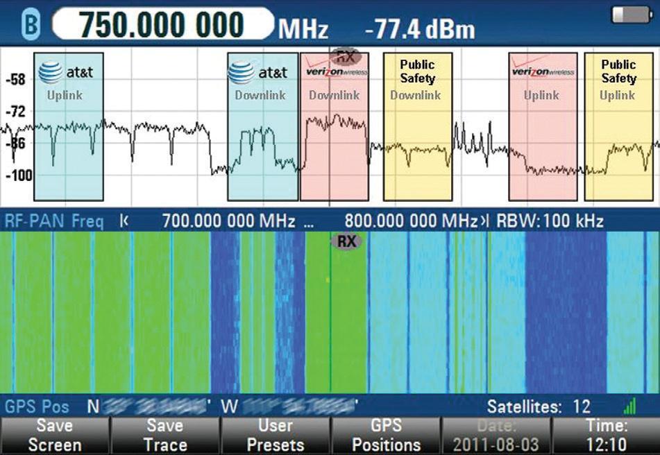
16 What ATT and Verizon are finding Leaking CATV devices using a portable spectrum analyzer and directional antennas. R&S
17


18 Here the measurement was made at a distance of 10 ft with an 11dBi Yagi at 780 MHz. The signal level at the top of the QAM at the input of the SA is -25dBmV for the 30kHz ResBW. The field strength calculation at 10 ft comes out to a substantial 2200µV/m. Courtesy Verizon

19 Courtesy Verizon

20 Courtesy Verizon


21 Courtesy Verizon

22 Courtesy Verizon

23 Courtesy Verizon

24 Courtesy Verizon

25 Courtesy Verizon

26 Courtesy Verizon
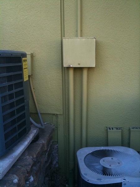
27 What CATV operators are finding causes of high frequency leakage Holes in Cable Thin Cracks / ring cracks in Cable Leaking Tap Face Plates / Bad fitting of the metallic gasket Broken connectors Loose Connectors Illegal connections
28 LTE Egress Interference The CATV system interfering with LTE We will look at multiple examples of this. Typical locations that cause these issue are: Loose or damaged hardline connectors, insufficiently shielded splitters, switches, amplifiers, as well as unterminated outlets which are common egress sources. Keep in mind that any egress locations are potential ingress locations for the CATV system as well. In addition, common physical defects responsible for egress include ring cracks in the coaxial cables, damage from chewing/gnawing by animals, loose covers, loose hardline connectors, faulty AGC, etc. Illegals: Connections and alterations made by persons engaged in cable theft have also been reported as a serious source of problems: improperly spliced cables, poor-quality materials, etc. Adding a Digital Leakage program in the upper band frequencies can ensure a much tighter plant. Egress: RF signal leaking out of the coaxial plant.
29 What we have discovered about Leaks at higher frequencies No real correlation or reason why some leaks are higher at low or high frequencies In many cases a very high leak in the 700MHz band will show no leak in the VHF frequency band These higher frequency leaks are typically at higher levels Possible reason are: In some part due to the tilt on outside plant Also higher frequencies travel more efficiently Mostly due to the component that is leaking Eg: cracks in the cable, leaking RF tap gasket, hole in cable
 > No correlation between low and high frequency.")
30 Digital Leakage Detection > This is a location where a tree grew through a cable on a busy thoroughfare a few blocks from a hub. > Hundreds of service vehicles drove past this location every day. It was a small analog leak that wasn t worth stopping for. (8uV/m low) > No correlation between low and high frequency. (We show this in the next few slides) > Very High leakage at 735MHz > Monitoring at just one frequency will not allow you to detect all leaks. > QAM Snare simultaneously detect leaks at Multiple Frequencies


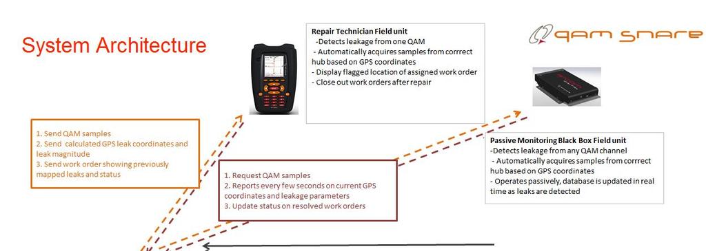
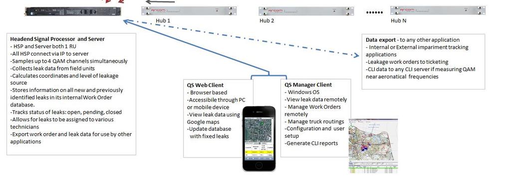
31 The technology > The process whereby QAM Snare detects and pinpoints leaks is fairly straightforward to explain: 1.Samples of the QAM channel are taken at the headend and transmitted to the field unit over a wireless network. * 2.The field unit compares these samples with signals pulled off of its antenna when there is correlation and the two signals are the same a leak has been detected. 3.After detection the next step is resolving the exact GPS coordinates of the leak, which is accomplished through an advanced technique called TDOA time difference of arrival. * With the QAM Snare Isolator used in the home, samples are acquired locally

 hyperbolic location QAM Snare is impervious to multipath/standing wave type issues that are")
32 Advanced location methodology Because of the employed correlation detection process and inherent time delay output we have a unique opportunity to make use of this data and employ the most accurate location methodology called Time Difference of Arrival (TDOA) to resolve the GPS location of the leak. Time difference of arrival (TDOA) hyperbolic location QAM Snare is impervious to multipath/standing wave type issues that are prevalent with analog detectors thereby making the final isolation process significantly easier.


 and LTE (750MHz) 567MHz 579MHz")
33 Simultaneous three channel detection QAM Snare is designed to detect and record leakage from any three digital channels simultaneously Typical choices are Aeronautical ( MHz), Mid-band (550MHz) and LTE (750MHz) 567MHz 579MHz 729MHz
34 Understanding a Leak Is it the same level at low and high frequencies? You would think that a leak acts like a wideband antenna but it does not. Can you still have a leak if traditional leakage in the 108 to 140 MHz range show nothing? Findings show little to no correlation across the spectrum. Leak strength at one frequency shows no correlation to leak strength at another. What does this mean for operators?
35 Lack of correlation of leaks from one band to another Low Frequency only Low and High Frequency High Frequency only
36 Combined leaks on one graph
37 Leaks in different frequency bands are due to different sets of problems Aeronautical band below 200MHz 96% drops and soft cable issues 300Mhz to 500MHz 40% drops-60% small cable issues and loose devices 600 to 900MHz 90% Hard line issues and 10% other and LTE


38 3 Channel Detection Red Flags are leaks >100uV/m, Yellow uV/m, Green <20uV/m We re seeing on average one high frequency leak per mile. Operators don t have the manpower or time to fix all of these leaks of varying levels. It s imperative that operators accurately measure the leak levels affecting the LTE band in order to prioritize where to work.

39 3 Frequency Leakage Comparison A sample of some interesting leaks from a deployment. QAM Snare was set to do 3 frequencies simultaneously. There is a wide range of differences in leak levels between 141Mhz, 561MHz and 711MHz.

40 Dramatic Differences in Frequency Response This tap was leaking 112uV/m at 729MHz. With an 18dB difference between 600MHz and 700MHz, the leak would only measure 14uV/m around 600MHz. 14uV/m is probably not a level that an operator would prioritize to fix yet this device was clearly causing LTE interference and had a higher leak in the LTE band.
41 Benefits of frequency agile detection Better coverage of your network Better network performance by focusing on frequencies being interfered with or causing interference The ability to assign work based on skill level and job focus Ability to know and schedule work to prevent issues now and in the future Better protection of your network Right technician for the area of focus
42

43 Implementation options: Navigator and Isolator used in companion to find and fix leaks: QAM Snare Navigator: QAM Snare Isolator: Navigator: Permanently mounted in vehicle Gets the technician to the leak zone Data bridge to Isolator Can switch to different frequencies as necessary Isolator: Used for close-in troubleshooting of the exact device Displays what the Navigator currently sees (Truck mode) or displays leaks measured off of its antenna (Walk mode)
44 Implementation options: Monitor used for passive detection repair later: QAM Snare Monitor: Monitor: Permanently mounted in vehicle Continuously reports leaks data to Headend Signal processor Designed to detect and locate leaks with no user involvement


45 Implementation options: QAM Snare Web Client QAM Snare Isolator: Monitor, Isolator, and Web Client used in companion to fix previously identified leaks. Web Client: Use Google maps to display the location of known leaks. Display Work Orders Fix and update leaks status in real time. Either PC or smartphone based Monitor: Data bridge to Isolator Isolator: Truck mode or Walk mode In Truck mode will provide audible feedback QAM Snare Monitor:


46 Implementation options: Isolator pair - for the fulfillment technician to detect leaks within the home. Isolator in the transmit mode: Acquires samples locally, sends to the second isolator with antenna Connect to a drop anywhere in the house Isolator in the detector mode: Walk around the home or MDU to find the source of the leak. QAM samples and timing over ISM transceiver chipset
47 QAM Snare System Demo Location #1


48 Flag uV/m at 711MHz 5868 Beachwalk Dr At Flag 89 we found a cracked tap housing that subsequently broke off. No analog leak was found.


49 Flag uV/m at 711MHz 5876 Goulagong Dr Burnt out tap with suck out around 470MHz..


50 Flag uV/m 5397 Gale Dr At this location the tap was missing a screw in the tap plate. This is a good example of our TDOA technology for calculating the GPS coordinates of a leak. As can be seen from the screen shot in the Client software, the QAM Snare Navigator had visibility to the leak from a far distance as indicated by the red data points. TDOA put the flag at the exact location of the leak.


51 Flag uV/m at 711MHz 5902 Woodstock Ct Radial crack in the feeder cable.

52 Flag uV/m 5878 Clear Springs Rd Drop cable had crimp on connector. Pulled drop cable out of the connector. This dropped the leak down in level but a smaller leak was still detected. The tap screws were also loose.


53 Flag uV/m 749 Fiona Ln Flag 52 2 nd Tap At Flag 52 a PDU taps screws were extremely loose. The tap also showed a bit of corrosion. A second lower level leak was found at the next pole. The cause was also loose screws on a PDU tap.
54 QAM Snare System Demo Location #2

55 Two Leaks at one location Flag 7 Leak #1 at this location: Tech first found a bad drop with an old Digicon connector with the center pin loose. The tech replaced the F connector, reconnected the drop and the leak at 435 MHz dropped to zero. This was the cause of the 435MHz leak, but had nothing to do with the 729MHz leak which still remained. 729MHz 435MHz Leak #2 at this location: Tech checked the tap face plate and found that the gasket was twisted. To correct the gasket the tap plate was removed, and the gasket and tap plate were reset. This action cleared the leak at 729 MHz.
56 Three Leaks at one location Flag 4 729MHz 435MHz Leak level recorded at Isolator in bucket truck next to amp 729 MHz / 2100 µv/m 435MHz /3800 µv/m Resolution: First Leak #1 at this location: The technician found the power passing tap face plate to be loose. The tech tightened the face plate and the leak at 729 MHz dropped to 500 µv/m.
57 Resolution: Leak #2 and Leak #3 at this location: The tech realized that the back part of the tap was still loose and after looking closer he noticed the center seizure screw was also loose. He tightened down the seizure screw and the 435 MHz went away completely. He them tightened the back of the tap and the 729 MHz leak dropped as well. This location was a good example of multiple leaks existing at different frequencies, each caused by a different problem.
58 QAM Snare System Demo Location #3

59 Drive Routes From QAM Snare admin the drive routes and found leaks can be seen. For it s mapping software QAM Snare uses OpenStreetMap.org which is open source. Arcom can also incorporated node boundaries.
60 List of found leaks comparing QAM Snare and XYZ leakage detector Address QAM Snare (555 MHz) XYZ (112.7 MHz) 314 W Cottage ST 501 uv/m No 655 N Johnston Ave 355 uv/m 153 uv/m 1005 N Francis Ave 200 uv/m No 191 S Stadium Drive 178 uv/m No 1238 E 14th St. 141 uv/m No 1157 N Johnston Ave. 126 uv/m 50 uv/m 1147 N Francis Ave. 100 uv/m No 1972 Arlington St. 89 uv/m No 2376 E Woodland Dr. 79 uv/m No 1332 E 18th St 71 uv/m No 504 Short St. 71 uv/m No 1526 Arlington 63 uv/m 36 uv/m From the top 12 leaks QAM Snare found only three were picked up by the XYZ. This comparison is not intended to show the weakness in a competitors product but rather show the value in measuring leakage at the higher frequency. When actual leaks are found this validates the measured leaks.

61 Flag 8 501uV/m 314 W Cottage St. At Flag 8 we found a cracked hardline cable only visible from above with a bucket truck. The leak found by the XYZ was below 20uV/m and was not considered a large enough leak to be flagged.


62 Flag 5 355uV/m 655 N Johnston Ave. We found an illegal connection at this location. QAM Snare found a 355uV/m leak while XYZ showed this as a 153uV/m leak. The QAM Snare isolator lead us to the leak quickly, peaking while we pointed the antenna directly at the tap with the illegal connection.


63 Flag uV/m 1157 N Johnston Ave. At this location we found a combination of three leak problems. We found two leaks around from the amplifier and the tap located close to the home. One leak was reduced in strength by tightening the seizure screw coming out the amp. The gasket on the tap was the other problem. We replaced the face plate on the tap as well as a new gasket and the leak dropped by another 30 db. We also found an unterminated drop cable on the right hand corner of the home. The isolator helped find all three problems. XYZ did not detect a leak at this location.

64 Summary: Digital Leakage Detection > Detects digital channels leaking from the network Find leaks quicker and with greater accuracy compared to the status quo technology use leakage tools not just for compliance but as a network maintenance tool Gain visibility to a widespread set of hardline impairments where there was previously no visibility: high frequency leaks that are invisible to analog detection methods Find egress affecting LTE Find forward ingress at any frequency In an all digital network, no need to reserve an analog channel for FCC compliance
65 Work Flow Automatically route leakage work orders to technicians Assign work orders based on leak frequency and technician level High frequency leaks go to hardline maintenance Mid frequency distribution cable issues, loose face plates, splitters etc.. Low frequency leaks go to installers Prioritize high frequency work orders by proximity to cell towers Immediate notification of high level leak over programmable threshold Route work orders by hub or node groups Route work orders in proximity groups Route work orders by technician home address


66 Work Flow Impairment Resolution 7 options for closing out work orders QS Manager software Tech laptop and Webview On the QS Navigator Smartphone Paper work order ed work order Raw data export to Remedy or Unified
67 QAM Snare Differentiators 1. QAM Snare has no need to inject a carrier. So no concerns to an injected carrier frequency drift or level stability, and no concerns of interference with adjacent QAMs. 2. Frequency agile from 133 to 885MHz. Operator can use any broadcast QAM and can change detection frequencies with a couple pushes of a button. 3. Because we utilize time delay we are able to implement an advanced TDOA location algorithm. The benefit is high accuracy of the location of the leak allowing less time 4. QAM Snare is impervious to multipath a huge issue and time saver in the final detection step, again significantly reducing troubleshooting time. 5. No false alarms. On some analog systems, up to 30% of alarms may be bogus a big waste of resources. Eliminate leak not found from your terminology. 6. No low vehicle speed limits for detection and no doppler issues. Competitors limit is 30MPH. 7. QAM Snare will work with any channel bandwidth so it is fully compatible with any future downstream channel bonding or OFDM modulation. 8. Integrated real time leak database. 9. Compatible with and able to be used for flyovers.
68 Thank you Kendall Robinson Regional Account Director Website:
Digital Leakage Today
 Digital Leakage Today Analog and Digital Leakage LTE interference Kendall Robinson Regional Account Director Arcom Digital Digital Leakage Outline Digital Leakage Traditional Leakage LTE Ingress and Egress
QAM Snare Isolator User Manual
 QAM Snare Isolator User Manual QS-ISO-1.6 9/1/15 This document details the functions and operation of the QAM Snare Isolator leakage detector Table of Contents Overview... 3 Screen Navigation... 4 Settings...
LTE Interference UHF Leakage
 LTE Interference UHF Leakage Ron Hranac Technical Leader Cisco Systems Nick Segura Director, Technical Operations Charter Communications 1 AGENDA Challenges of UHF leakage and LTE interference What s in
A METHOD OF CERTIFICATION FOR LTE SMALL CELLS IN THE HFC NETWORK
 A METHOD OF CERTIFICATION FOR LTE SMALL CELLS IN THE HFC NETWORK 185 AINSLEY DRIVE SYRACUSE, NY 13210 800.448.1655 I WWW.ARCOMDIGITAL.COM One of the problems associated with installations of LTE Small
QAM Snare Snoop User Manual
 QAM Snare Snoop User Manual QS-Snoop-v2.0 2/21/2018 This document details the functions and operation of the QAM Snare Snoop leakage detector Table of Contents Overview... 5 Screen Navigation... 6 Settings...
Signal Leakage Patrolling in the 700 MHz Frequency Band
 Signal Leakage Patrolling in the 700 MHz Frequency Band Welcome to the 1 st Quarter 2013 CSEI Technical Report. My last technical report, in the 2 nd Qtr of 2012 (the 3 rd & 4 th quarters of 2012 were
Application Note: PathTrak QAMTrak Analyzer Functionality. Overview
 Overview Increasing customer demand for upstream bandwidth is a welcomed challenge for MSO s as it often stems from growth in profitable bi-directional applications like VoIP and advanced video services.
XCOR TODAY S APPROACH TO DETECTING COMMON PATH DISTORTION
 ADVANCED TECHNOLOGY XCOR TODAY S APPROACH TO DETECTING COMMON PATH DISTORTION 185 AINSLEY DRIVE SYRACUSE, NY 13210 800.448.1655 / WWW.ARCOMDIGITAL.COM A NEED FOR CHANGE ADVANCED TECHNOLOGY Cable networks
QAM Snare Navigator Plus User Manual
 QAM Snare Navigator Plus User Manual QS-NAVPLUS-v1.11 7/2/18 This document details the functions and operation of the QAM Snare Navigator Plus leakage detector configured with firmware version N3.43.10
QAM Snare Navigator Plus User Manual
 QAM Snare Navigator Plus User Manual QS-NAVPLUS-v1.8 5/25/17 This document details the functions and operation of the QAM Snare Navigator Plus leakage detector configured with firmware version N3.35.9
Quiver User Guide. Xcor-QUG-v /13/12
 Quiver User Guide Xcor-QUG-v.3.0.4 8/13/12 This document details the full features and functionality of Quiver. Included is information on the various modes of operation and instruction on how to best
User's Manual F10G-5S-LCD 1 / 20 BOOST CELL PHONE SIGNAL BOOSTERS MADE BY HUAPTEC
 User's Manual F10G-5S-LCD 1 / 20 BOOST CELL PHONE SIGNAL BOOSTERS MADE BY HUAPTEC Table of contents WHAT IS INCLUDED... 3 1 HOW IT WORKS... 3 2 TOOL REQUIRED... 3 3 HOW TO INSTALL YOUR NEW CELLULAR BOOSTER...
CPD POINTER PNM ENABLED CPD DETECTION FOR THE HFC NETWORK WHITE PAPER ADVANCED TECHNOLOGY
 ADVANCED TECHNOLOGY CPD POINTER PNM ENABLED CPD DETECTION FOR THE HFC NETWORK WHITE PAPER 185 AINSLEY DRIVE SYRACUSE, NY 13210 800.448.1655 I WWW.ARCOMDIGITAL.COM The continued evolution of Proactive Network
QAM Snare Navigator Quick Set-up Guide- GSM version
 QAM Snare Navigator Quick Set-up Guide- GSM version v1.0 3/19/12 This document provides an overview of what a technician needs to do to set up and configure a QAM Snare Navigator GSM version for leakage
AN INTRODUCTION TO A NEW MICRO-REFLECTION LOCATION TECHNOLOGY
 ADVANCED TECHNOLOGY AN INTRODUCTION TO A NEW MICRO-REFLECTION LOCATION TECHNOLOGY 185 AINSLEY DRIVE SYRACUSE, NY 13210 800.448.1655 / WWW.ARCOMDIGITAL.COM ADVANCED TECHNOLOGY AN INTRODUCTION TO AN ENTIRELY
Understanding and Troubleshooting Linear Distortions: Micro-reflections, Amplitude Ripple/Tilt and Group Delay
 Understanding and Troubleshooting Linear Distortions: Micro-reflections, Amplitude Ripple/Tilt and Group Delay RON HRANAC 1 A Clean Upstream: Or Is It? Graphic courtesy of Sunrise Telecom 2 Transmission
A DISCUSSION ON QAM SNARE SENSITIVITY
 ADVANCED TECHNOLOGY A DISCUSSION ON QAM SNARE SENSITIVITY HOW PROCESSING GAIN DELIVERS BEST SENSITIVITY IN THE CATEGORY 185 AINSLEY DRIVE SYRACUSE, NY 13210 800.448.1655 / WWW.ARCOMDIGITAL.COM ADVANCED
QAM Snare Navigator Quick Set-up Guide- Wi-Fi version
 QAM Snare Navigator Quick Set-up Guide- Wi-Fi version v1.0 3/19/12 This document provides an overview of what a technician needs to do to set up and configure a QAM Snare Navigator Wi-Fi version for leakage
2012 LitePoint Corp LitePoint, A Teradyne Company. All rights reserved.
 LTE TDD What to Test and Why 2012 LitePoint Corp. 2012 LitePoint, A Teradyne Company. All rights reserved. Agenda LTE Overview LTE Measurements Testing LTE TDD Where to Begin? Building a LTE TDD Verification
Frequency Division Multiplexing and Headend Combining Techniques
 Frequency Division Multiplexing and Headend Combining Techniques In the 3 rd quarter technical report for 2010, I mentioned that the next subject would be wireless link calculations and measurements; however,
LTE Signal Quality Analysis. BTS Master, Cell Master,, Spectrum Master
 LTE Signal Quality Analysis BTS Master, Cell Master,, Spectrum Master Slide 1 Anritsu LTE Test Instrument Portfolio Signaling Tester Fading Simulator Signal Analyzers Vector Signal Generator Radio Communication
Appearance of device and accessories may vary.
 Tri-Band 4G-V Adjustable Gain 700 (Band 13) / 800 / 1900 MHz In-Building Wireless Smart Technology Signal Booster (Band 13 is 700 MHz Verizon LTE) Tri-Band 4G-A Adjustable Gain 700 (Band 12/17) / 800 /
INSTALLATION AND OPERATING MANUAL
 INSTALLATION AND OPERATING MANUAL FOR RBDA-PCS-1/25W-90-A INDOOR REPEATER TABLE OF CONTENTS PARAGRAPH PAGE NO BDA OVERVIEW 3 BDA BLOCK DIAGRAM DESCRIPTION 3 FCC INFORMATION FOR USER 3 BDA BLOCK DIAGRAM
SmartScan. Application Note. Intelligent Frequency Response and Limits in Plant Distribution. VIAVI Solutions
 Application Note SmartScan Intelligent Frequency Response and Limits in Plant Distribution VIAVI Solutions As signals travel through the coaxial cable network they are attenuated more at higher frequencies.
SEARCH LITE OPERATION MANUAL
 SEARCH LITE OPERATION MANUAL Corporate Profile Trilithic, Inc. was founded in 1986 as an engineering and assembly company providing customized communications and routing systems for business and government
Lecture LTE (4G) -Technologies used in 4G and 5G. Spread Spectrum Communications
 -Technologies used in 4G and 5G. Spread Spectrum Communications") COMM 907: Spread Spectrum Communications Lecture 10 - LTE (4G) -Technologies used in 4G and 5G The Need for LTE Long Term Evolution (LTE) With the growth of mobile data and mobile users, it becomes essential
COMM 907: Spread Spectrum Communications Lecture 10 - LTE (4G) -Technologies used in 4G and 5G The Need for LTE Long Term Evolution (LTE) With the growth of mobile data and mobile users, it becomes essential
2016 Spring Technical Forum Proceedings
 Full Duplex DOCSIS Technology over HFC Networks Belal Hamzeh CableLabs, Inc. Abstract DOCSIS 3.1 technology provides a significant increase in network capacity supporting 10 Gbps downstream capacity and
2016 Spring Technical Forum Proceedings
 Leakage Detection Using Test Signal Phase with GPS Authors: Thomas H Williams and Colin Justis Cable Television Laboratories, Inc. Abstract This paper describes a leakage detection system that measures
SolidRF SOHO Tri-Band Cell Phone Signal Booster for GSM, GPRS, CDMA 3G and Verizon 4G LTE. 700 MHz(Band 13) / 850 MHz / 1900 MHz ONLY
 / 850 MHz / 1900 MHz ONLY") SolidRF SOHO Tri-Band Cell Phone Signal Booster for GSM, GPRS, CDMA 3G and Verizon 4G LTE 700 MHz(Band 13) / 850 MHz / 1900 MHz ONLY If you have any questions or concerns when installing or operating your
SolidRF SOHO Tri-Band Cell Phone Signal Booster for GSM, GPRS, CDMA 3G and Verizon 4G LTE 700 MHz(Band 13) / 850 MHz / 1900 MHz ONLY If you have any questions or concerns when installing or operating your
CX380X Advanced Spectrum and Burst QAM Analyzer
 Advanced Spectrum and Burst QAM Analyzer Preventative Network Monitoring With VeEX s VeSion system, the advanced Spectrum Analyzer and Bursty Demodulator captures rogue cable modems and provides proactive
F10F Series Wide band booster User s Manual
 F10F Series Wide band booster User s Manual Directory F10F Series Booster User s Manual 1. Abbreviations 2 2. Safety Warnings 2 3. Application 3 4. Introduction 4 5. System Characteristics 5 5.1. Features
Wilson. iden 800 MHz. Adjustable Gain In-Building Wireless Smart Technology Signal Booster. Appearance of device and accessories may vary.
 iden 800 MHz Adjustable Gain In-Building Wireless Smart Technology Contents: Options & Accessories....................... 1 Quick Install Overview............................... 2 Installation Diagram.................................
Guide. Installation. Wilson Electronics, Inc. In-Building Wireless Amplifi er. Contents:
 Amplifier Installation Guide In-Building Wireless Amplifi er Contents: Guarantee and Warranty 1 Antenna Options and Accessories 2 Before Getting Started / How It Works 3 Installation Overview 4 Installing
Screening Attenuation When enough is enough
 Screening Attenuation When enough is enough Anders Møller-Larsen, Ph.D. M.Sc. E.E. Product Manager, Coax Network Introduction This white paper describes the requirements to screening attenuation of cables
Satellite Communications Testing
 Satellite Communications Testing SATELLITE COMMUNICATIONS TESTING Traditionally, the satellite industry has relied on geosynchronous earth orbit (GEO) satellites that take years to build and require very
Planning of LTE Radio Networks in WinProp
 Planning of LTE Radio Networks in WinProp AWE Communications GmbH Otto-Lilienthal-Str. 36 D-71034 Böblingen mail@awe-communications.com Issue Date Changes V1.0 Nov. 2010 First version of document V2.0
Spectrum & Power Measurements Using the E6474A Wireless Network Optimization Platform Application Note By Richard Komar
 Spectrum & Power Measurements Using the E6474A Wireless Network Optimization Platform Application Note By Richard Komar Contents Introduction...1 Band Clearing...2 Using the spectrum analyzer for band
RECOMMENDATION ITU-R BT.1832 * Digital video broadcast-return channel terrestrial (DVB-RCT) deployment scenarios and planning considerations
 deployment scenarios and planning considerations") Rec. ITU-R BT.1832 1 RECOMMENDATION ITU-R BT.1832 * Digital video broadcast-return channel terrestrial (DVB-RCT) deployment scenarios and planning considerations (Question ITU-R 16/6) (2007) Scope This
Rec. ITU-R BT.1832 1 RECOMMENDATION ITU-R BT.1832 * Digital video broadcast-return channel terrestrial (DVB-RCT) deployment scenarios and planning considerations (Question ITU-R 16/6) (2007) Scope This
HFC Cable Architecture
 HFC Cable Architecture Wade Holmes wade.holmes@gmail.com 3/22/2018 [all images from CableLabs, Cisco, Arris or otherwise noted] Agenda Overview of Cable as a technology: what the future holds Architecture
CELLULAR DISTRIBUTION SYSTEM
 Overview OCC s patented Cellular Distribution System (CDS) is a wireless enhancement product designed to resolve low cellular signal strength issues for in-building applications. Designed as a complete
Page 1. Overview : Wireless Networks Lecture 9: OFDM, WiMAX, LTE
 Overview 18-759: Wireless Networks Lecture 9: OFDM, WiMAX, LTE Dina Papagiannaki & Peter Steenkiste Departments of Computer Science and Electrical and Computer Engineering Spring Semester 2009 http://www.cs.cmu.edu/~prs/wireless09/
Optimize Cell-Site Deployments
 Optimize Cell-Site Deployments CellAdvisor BBU Emulation Mobile operators continue to face an insatiable demand for capacity, driven by multimedia applications and the ever-increasing number of devices
10/17/2011. I have an Air-Card. I have Satellite Internet. Why would I use Wi-Fi? Just for
 How much do you use the Internet? Just for e-mail Or. 2011 National HDT Rally How much do you use the Internet? How much do you use the Internet? E-mail Face Book Google Plus Blog reading Blog Writing
Unit 3 - Wireless Propagation and Cellular Concepts
 X Courses» Introduction to Wireless and Cellular Communications Unit 3 - Wireless Propagation and Cellular Concepts Course outline How to access the portal Assignment 2. Overview of Cellular Evolution
HPQI-2 QAM Pilot Generator Users Guide
 HPQI-2 QAM Pilot Generator Users Guide Document No. 201903081006 Revision 0 3/29/2019 This document details how to setup and configure the Arcom Digital HPQI-2 Headend QAM Pilot Generator Table of Contents
University of Bristol - Explore Bristol Research. Link to publication record in Explore Bristol Research PDF-document.
 Mansor, Z. B., Nix, A. R., & McGeehan, J. P. (2011). PAPR reduction for single carrier FDMA LTE systems using frequency domain spectral shaping. In Proceedings of the 12th Annual Postgraduate Symposium
NOISE, INTERFERENCE, & DATA RATES
 COMP 635: WIRELESS NETWORKS NOISE, INTERFERENCE, & DATA RATES Jasleen Kaur Fall 2015 1 Power Terminology db Power expressed relative to reference level (P 0 ) = 10 log 10 (P signal / P 0 ) J : Can conveniently
Overview of IEEE Broadband Wireless Access Standards. Timo Smura Contents. Network topologies, frequency bands
 Overview of IEEE 802.16 Broadband Wireless Access Standards Timo Smura 24.02.2004 Contents Fixed Wireless Access networks Network topologies, frequency bands IEEE 802.16 standards Air interface: MAC +
Interference management Within 3GPP LTE advanced
 Interference management Within 3GPP LTE advanced Konstantinos Dimou, PhD Senior Research Engineer, Wireless Access Networks, Ericsson research konstantinos.dimou@ericsson.com 2013-02-20 Outline Introduction
F10-GSM Single System
 F10-GSM Single System 1 Table of content How it works... 3 Package contents... 4 Install your hardware... 5 Troubleshooting... 14 Specifications... 15 Product Warranty... 16 Safety Warnings... 17 2 How
User Warnings MUST READ!
 Abbreviations....2 Safety..2 1. Preface... 3 2. Introduction / Features & Functions..5 3. Installation.7 3.1 Installation Procedure... 8 3.1 Installation Procedure Con t 9 Terminology AGC BTS CDMA db DL
F10I-EGSM Single System
 F10I-EGSM Single System 1 Table of contents How it works... 3 Package contents... 4 Troubleshooting... 14 Specifications... 15 Product Warranty... 16 Safety Warnings... 17 2 How it works Huaptec F10I-EGSM
Guide. Installation. Wilson Electronics, Inc. In-Building Wireless Amplifi er. Contents:
 Amplifier Installation Guide In-Building Wireless Amplifi er Contents: Guarantee and Warranty 1 Antenna Options and Accessories 2 Before Getting Started / How It Works 2 Installation Overview 3 Installation
Intermodulation Distortion in RF Connectors
 a division of RF Industries Intermodulation Distortion in RF Connectors Introduction Intermodulation distortion or IMD has always existed in RF transmission paths. Until about the early 1990 s, cellular
Technician License Course Chapter 3 Types of Radios and Radio Circuits. Module 7
 Technician License Course Chapter 3 Types of Radios and Radio Circuits Module 7 Radio Block Diagrams Radio Circuits can be shown as functional blocks connected together. Knowing the description of common
Are You Ready for DOCSIS 3.1. Presenter: Pete Zarrelli VeEX Field Applications Engineer
 Are You Ready for DOCSIS 3.1 Presenter: Pete Zarrelli VeEX Field Applications Engineer Today s Speaker Pete Zarrelli Senior Field Engineer VeEX Inc. (215) 514-1083 pete@veexinc.com 14 Years PBX/Business
Submission on Proposed Methodology for Engineering Licenses in Managed Spectrum Parks
 Submission on Proposed Methodology and Rules for Engineering Licenses in Managed Spectrum Parks Introduction General This is a submission on the discussion paper entitled proposed methodology and rules
PRA Series of Radio and TV Amplifier Power Supplies
 PRA Series of Radio and TV Amplifier Power Supplies The PRA 420 is an antenna power supply, low noise MMIC amplifier and splitter combination to supply up to 24 Shipboard Radios and /or TV Receivers. It
Complimentary Reference Material
 Complimentary Reference Material This PDF has been made available as a complimentary service for you to assist in evaluating this model for your testing requirements. TMG offers a wide range of test equipment
Making Noise in RF Receivers Simulate Real-World Signals with Signal Generators
 Making Noise in RF Receivers Simulate Real-World Signals with Signal Generators Noise is an unwanted signal. In communication systems, noise affects both transmitter and receiver performance. It degrades
Transmission Media. Transmission Media 12/14/2016
 Transmission Media in data communications DDE University of Kashmir By Suhail Qadir System Analyst suhailmir@uok.edu.in Transmission Media the transmission medium is the physical path between transmitter
Bluetooth BlueTooth - Allows users to make wireless connections between various communication devices such as mobile phones, desktop and notebook comp
 ECE 271 Week 8 Bluetooth BlueTooth - Allows users to make wireless connections between various communication devices such as mobile phones, desktop and notebook computers - Uses radio transmission - Point-to-multipoint
The Physical Layer Outline
 The Physical Layer Outline Theoretical Basis for Data Communications Digital Modulation and Multiplexing Guided Transmission Media (copper and fiber) Public Switched Telephone Network and DSLbased Broadband
CHAPTER - 6 PIN DIODE CONTROL CIRCUITS FOR WIRELESS COMMUNICATIONS SYSTEMS
 CHAPTER - 6 PIN DIODE CONTROL CIRCUITS FOR WIRELESS COMMUNICATIONS SYSTEMS 2 NOTES 3 INTRODUCTION PIN DIODE CONTROL CIRCUITS FOR WIRELESS COMMUNICATIONS SYSTEMS Chapter 6 discusses PIN Control Circuits
Keysight Technologies Performing LTE and LTE-Advanced RF Measurements with the E7515A UXM Wireless Test Set
 Keysight Technologies Performing LTE and LTE-Advanced RF Measurements with the E7515A UXM Wireless Test Set Based on 3GPP TS 36.521-1 Application Note 02 Keysight Performing LTE and LTE-Advanced Measurements
Urban WiMAX response to Ofcom s Spectrum Commons Classes for licence exemption consultation
 Urban WiMAX response to Ofcom s Spectrum Commons Classes for licence exemption consultation July 2008 Urban WiMAX welcomes the opportunity to respond to this consultation on Spectrum Commons Classes for
Intermodulation Distortion in RF Connectors
 Intermodulation Distortion in RF Connectors Introduction Intermodulation distortion or IMD has always existed in RF transmission paths. Until about the early 1990 s, cellular communications had relatively
Schedule. Presenter & Moderator. Questions
 Schedule 2:00 3:00 pm EST ControlCam Presentation Presenter & Moderator Presenter Lauren Kane, VP of Marketing & Customer Engagement 904-758-2601 LaurenKane@ControlCam.com Moderator Paige Parker, VP of
Mitigating Interference & Maximizing Throughput in 700MHz for SCADA
 Mitigating Interference & Maximizing Throughput in 700MHz for SCADA Paul Reid and Kathy Shaft (GRE) October 2018 WAS SPUN OUT OF 2 3 Phoenix US Headquarters US Headquarters Technical Support Hub Repair
IT-24 RigExpert. 2.4 GHz ISM Band Universal Tester. User s manual
 IT-24 RigExpert 2.4 GHz ISM Band Universal Tester User s manual Table of contents 1. Description 2. Specifications 3. Using the tester 3.1. Before you start 3.2. Turning the tester on and off 3.3. Main
Co-Existence of UMTS900 and GSM-R Systems
 Asdfadsfad Omnitele Whitepaper Co-Existence of UMTS900 and GSM-R Systems 30 August 2011 Omnitele Ltd. Tallberginkatu 2A P.O. Box 969, 00101 Helsinki Finland Phone: +358 9 695991 Fax: +358 9 177182 E-mail:
SuperHALO. 2G-3G-4G Wireless Adjustable Cellular Booster Kit. CA-VAT-10-R User Guide. Introduction Installation Troubleshooting 9-10
 SuperHALO TM 2G-3G-4G Wireless Adjustable Cellular Booster Kit Introduction 1-2 Theory of Operation Packages Contents Booster Hardware 1 2 2 Installation 3-8 Quick Install Guide Configuring Gain Settings
William Stallings Data and Computer Communications. Bab 4 Media Transmisi
 William Stallings Data and Computer Communications Bab 4 Media Transmisi Overview Guided - wire Unguided - wireless Characteristics and quality determined by medium and signal For guided, the medium is
Technical Manual. Mobile Communication Mini Booster Model: PW-MB or PW-MB10-900
 Technical Manual Mobile Communication Mini Booster Model: PW-MB10-800 or PW-MB10-900 PW-MB10-2100 or PW-MB10-1800 Page 1 Table of Contents Introduction Name & Function How to install the system User Attentions
CT-2 and CT-3 Channel Taggers OPERATION MANUAL
 CT-2 and CT-3 Channel Taggers OPERATION MANUAL Trilithic Company Profile Trilithic is a privately held manufacturer founded in 1986 as an engineering and assembly company that built and designed customer-directed
Direct Link Communication II: Wireless Media. Current Trend
 Direct Link Communication II: Wireless Media Current Trend WLAN explosion (also called WiFi) took most by surprise cellular telephony: 3G/4G cellular providers/telcos/data in the same mix self-organization
User Warnings MUST READ!
 Abbreviations....2 Safety..2 1. Preface... 3 2. Introduction / Features & Functions..5 3. Installation.7 3.1 Installation Procedure... 8 3.1 Installation Procedure Con t 9 Terminology AGC BTS CDMA db DL
Mobile Communication Services on Aircraft Publication date: May /34/EC Notification number: 2014/67/UK
 Draft UK Interface Requirement 2070 Mobile Communication Services on Aircraft Publication date: May 2014 98/34/EC Notification number: 2014/67/UK Contents Section Page 1 References 3 2 Foreword 4 3 Minimum
TDD and FDD Wireless Access Systems
 WHITE PAPER WHITE PAPER Coexistence of TDD and FDD Wireless Access Systems In the 3.5GHz Band We Make WiMAX Easy TDD and FDD Wireless Access Systems Coexistence of TDD and FDD Wireless Access Systems In
Cellular Coverage Workgroup. A Hotelier s Guide to Cellular Coverage Solutions. Solution Architectures
 Cellular Coverage Workgroup A Hotelier s Guide to Cellular Coverage Solutions Version 1.00 About HTNG (HTNG) is a non-profit association with a mission to foster, through collaboration and partnership,
RMS Communications TECHNICAL BRIEF
 TECHNICAL BRIEF BROADBAND CATV Coaxial Network Demands Today: Introducing Intermodulation: Its Role in Cable Modem and Reverse Path Operation RF Products Division A History of CATV Coaxial Network Design:
Cell Extender Antenna System Design Guide Lines
 Cell Extender Antenna System Design Guide Lines 1. General The design of an Antenna system for a Cell Extender site needs to take into account the following specific factors: a) The systems input and output
Data and Computer Communications Chapter 4 Transmission Media
 Data and Computer Communications Chapter 4 Transmission Media Ninth Edition by William Stallings Data and Computer Communications, Ninth Edition by William Stallings, (c) Pearson Education - Prentice Hall,
What s In The Box. 1x, 2x, or 4x Indoor Antenna(s)* Coaxial Cable. Other Parts. 2x, 3x, or 5x 30 ft RS400 Cable* 1x 1 ft RS240 Cable** Panel Antenna
* Coaxial Cable. Other Parts. 2x, 3x, or 5x 30 ft RS400 Cable* 1x 1 ft RS240 Cable** Panel Antenna") Read This First CEL-FI GO X Installation Guide 26081 Merit Circle, Suite 118 Laguna Hills, CA 92653 +1 (800) 761-3041 www.repeaterstore.com contact@repeaterstore.com What s In The Box Cel-Fi GO X Amplifier
Read This First CEL-FI GO X Installation Guide 26081 Merit Circle, Suite 118 Laguna Hills, CA 92653 +1 (800) 761-3041 www.repeaterstore.com contact@repeaterstore.com What s In The Box Cel-Fi GO X Amplifier
PRACTICAL CONSIDERATIONS
 WIRELESS DOCSIS TM CABLE EXTENSION PRACTICAL CONSIDERATIONS DAN CASTELLANO VP SALES AND BUSINESS DEVELOPMENT Arcwave Inc. 910 Campisi Way, Ste 1C Campbell, CA 95008 Office (408) 558-2300, Fax (408) 558-2302
WiMAX/ Wireless WAN Case Study: WiMAX/ W.wan.6. IEEE 802 suite. IEEE802 suite. IEEE 802 suite WiMAX/802.16
 W.wan.6-2 Wireless WAN Case Study: WiMAX/802.16 W.wan.6 WiMAX/802.16 IEEE 802 suite WiMAX/802.16 PHY Dr.M.Y.Wu@CSE Shanghai Jiaotong University Shanghai, China Dr.W.Shu@ECE University of New Mexico Albuquerque,
Correlation & vtdr! Understanding correlation groups and vtdr (virtual time domain reflectometer are key to unleashing PNM power
 Correlation & vtdr Understanding correlation groups and vtdr (virtual time domain reflectometer are key to unleashing PNM power vtdr and Correlation groups operate together to help locate outside plant
Fading & OFDM Implementation Details EECS 562
 Fading & OFDM Implementation Details EECS 562 1 Discrete Mulitpath Channel P ~ 2 a ( t) 2 ak ~ ( t ) P a~ ( 1 1 t ) Channel Input (Impulse) Channel Output (Impulse response) a~ 1( t) a ~2 ( t ) R a~ a~
Compact Model Fiber Deep Node 862 MHz with 42/54 MHz Split
 Optoelectronics Compact Model 90090 Fiber Deep Node 862 MHz with 42/54 MHz Split Description The Scientific-Atlanta Compact Model 90090 Fiber Deep Node is a small, low-cost, 110V AC powered node that addresses
Multi-Way Diversity Reception for Digital Microwave Systems
 Multi-Way Diversity Reception for Digital Microwave Systems White paper Table of Contents 1. GENERAL INFORMATION 3 1.1 About this document 3 1.2 Acknowledgements 3 2. THE NEED FOR DIVERSITY RECEPTION 3
Presentation Title Subhead Date
 Getting The Most Out Of Your Wireless Mics Presentation Title Subhead Date Best Practices: Antennas, RF Coordination & Hardware Dave Mendez Senior Market Development Specialist The Wisdom of Dilbert Antennas:
The Cellular Concept. History of Communication. Frequency Planning. Coverage & Capacity
 The Cellular Concept History of Communication Frequency Planning Coverage & Capacity Engr. Mian Shahzad Iqbal Lecturer Department of Telecommunication Engineering Before GSM: Mobile Telephony Mile stones
Products GSM900 CDMA800 DCS1800 PCS1900 C/G (2W) D/P (0.5W) Dual band Band selective Accessory
 D/P (0.5W) Dual band Band selective Accessory") Signal Booster Cell Phone signal booster is used to amplify the wireless signal in small area. The function is to send signal from base station to the indoor coverage directly, and through the small base
Signal Booster Cell Phone signal booster is used to amplify the wireless signal in small area. The function is to send signal from base station to the indoor coverage directly, and through the small base
L-DACS1/2 Data Link Analysis Part I: Functional Analysis
 L-DACS1/2 Data Link Analysis Part I: Functional Analysis Raj Jain Jain@ACM.ORG Presentation to Boeing February 4, 2010 1 Overview Application Aeronautical Datalink Evolution Spectrum Implications of Channel
Data and Computer Communications. Tenth Edition by William Stallings
 Data and Computer Communications Tenth Edition by William Stallings Data and Computer Communications, Tenth Edition by William Stallings, (c) Pearson Education - Prentice Hall, 2013 Wireless Transmission
Introduction to WiMAX Dr. Piraporn Limpaphayom
 Introduction to WiMAX Dr. Piraporn Limpaphayom 1 WiMAX : Broadband Wireless 2 1 Agenda Introduction to Broadband Wireless Overview of WiMAX and Application WiMAX: PHY layer Broadband Wireless Channel OFDM
Cellular Infrastructure and Standards while deploying an RDA
 Cellular Infrastructure and Standards while deploying an RDA Overview This whitepaper discusses the methods used while deploying an RDA into a field environment and dives into the standards used to judge
From 2G to 4G UE Measurements from GSM to LTE. David Hall RF Product Manager
 From 2G to 4G UE Measurements from GSM to LTE David Hall RF Product Manager Agenda: Testing 2G to 4G Devices The progression of standards GSM/EDGE measurements WCDMA measurements LTE Measurements LTE theory
Searcher Plus GT Leakage Detector OPERATION MANUAL
 Searcher Plus GT Leakage Detector OPERATION MANUAL 99 Washington Street Melrose, MA 02176 Phone 781-665-1400 Toll Free 1-800-517-8431 Visit us at www.testequipmentdepot.com Trilithic Company Profile Trilithic
PRINCIPLES OF COMMUNICATION SYSTEMS. Lecture 1- Introduction Elements, Modulation, Demodulation, Frequency Spectrum
 PRINCIPLES OF COMMUNICATION SYSTEMS Lecture 1- Introduction Elements, Modulation, Demodulation, Frequency Spectrum Topic covered Introduction to subject Elements of Communication system Modulation General