R5 SUPREME AIS Transponder System
|
|
|
- Christal Marshall
- 6 years ago
- Views:
Transcription


1 Saab TransponderTech R5 SUPREME AIS Transponder System OPERATION & INSTALLATION MANUAL
2 This page is intentionally empty
3 i Copyright The entire contents of this manual and its appendices, including any future updates and modifications, shall remain the property of Saab TransponderTech AB at all times. The contents must not, whether in its original form or modified, be wholly or partly copied or reproduced, nor used for any other purpose than the subject of this manual. Saab TransponderTech AB, SWEDEN ii Disclaimer While reasonable care has been exercised in the preparation of this manual, Saab TransponderTech AB shall incur no liability whatsoever based on the contents or lack of contents in the manual. iii Software This manual reflects the capabilities of the R5 SUPREME AIS Transponder with Software version and R5 SUPREME Control & Display Unit (CDU) with software version If the system since delivery has been updated from this version, such change should be reflected on a label on the unit. Current software versions in the system can always be verified in the S/W info dialog as described in section iv Manual Part Number and Revision Part number , revision A3. v Safety Instructions Note the following compass safe distances: Equipment R5 SUPREME Transponder Standard magnetic compass 0,65 m 0,40 m R5 SUPREME CDU 0,75 m 0,50 m Steering magnetic compass vi Disposal Instructions Broken or unwanted electrical or electronic equipment parts shall be classified and handled as Electronic Waste. Improper disposal may be harmful to the environment and human health. Please refer to your local waste authority for information on return and collection systems in your area. THE AUTOMATIC IDENTIFICATION SYSTEM , A3 Page 3
4 vii Contact Information For installation, service, ordering info and technical support please contact your local Saab TransponderTech representative. A list of dealers and service stations can be found on the corresponding product page at THE AUTOMATIC IDENTIFICATION SYSTEM , A3 Page 4
5 TABLE OF CONTENTS 1 The Automatic Identification System System Overview Product Description Installation Unpacking the Equipment Equipment Installation Environment Installation Cables System interconnection overview Installation Procedure Installing the R5 SUPREME CDU Installing the R5 SUPREME Transponder Install the R5 AIS Junction Box Mount the VHF Antenna Mount the GPS Antenna Electrical Installation details Configuration Configuration Wizard System Functional Check Configuration Parameters Operation General usage LED s on R5 SUPREME Transponder LED s and Controls on R5 SUPREME CDU Menu Structure Tree view Alarm and Alert Pop-ups Status Bar Status Icons View Remote Ship Information View Plot of Targets View Transmitted Own Ship Information Enter and Read Voyage Related Information Handling Safety Related Messages (SRM) and Text Messages Send Persons On Board Long Range Interrogations THE AUTOMATIC IDENTIFICATION SYSTEM , A3 Page 5
6 5.15 Regional Areas Alarms Status List Non Functional Time AIS Internal GPS Status View Raw Data SW/HW Info VHF Status Communication Test Update Software Restore Configuration Software Upgrade Upgrade Software in R5 SUPREME Transponder via Junction Box Upgrade Software in R5 SUPREME Transponder via CDU Upgrade Software in R5 SUPREME CDU Technincal Specifications R5 SUPREME Transponder R5 SUPREME CDU R5 AIS Junction Box Troubleshooting Troubleshooting Prerequisites Troubleshooting with the Front Panel LED s of the Transponder Troubleshooting with Alarm Messages Troubleshooting via the CDU Reporting Intervals for Class A Transponders F.A.Q Contacting Support Indication Messages Long Range Definitions Interpretation of Input Sentences GPS and Sensor Input Sentences General Input Sentences AIS Specific Input Sentences Long Range Input Sentences Proprietary Input Sentences THE AUTOMATIC IDENTIFICATION SYSTEM , A3 Page 6
7 10 Interpretation of Output Sentences Proprietary Output Sentences (PSTT) Long Range Output Sentences AIS Output Sentences Alternate System Setups Dual CDU Combined AIS and Navigation system setup Electrical Interfaces Transponder interface details R5 AIS Junction box Interfaces CDU Interface ports: Mechanical Drawings Transponder Physical Size and Mechanical Drawing CDU Physical Size and Mechanical Drawing CDU Gimbal Mount Physical Size and Mechanical Drawing CDU Cutout Measurements for Panel Mount CDU Mounting Frame cutout and dimensions R5 AIS Junction Box Physical Size and Mechanical Drawing GPS Antenna Physical Size and Mechanical Drawing Glossary Units Appendix A License Copy of the GNU General Public License THE AUTOMATIC IDENTIFICATION SYSTEM , A3 Page 7
8 1 THE AUTOMATIC IDENTIFICATION SYSTEM The Automatic Identification System (AIS) is a safety information system that was proposed as a worldwide standard in 1997 and adopted by IMO in The AIS system is standardized by ITU, IEC, IALA and IMO and is subject to approval by a certification body. The first type approved AIS transponder in the world was Saab TransponderTech s R3 Class A Transponder in AIS allows transceivers to automatically share static and dynamic data such as ship name, call sign, dimensions, position and sensor information on two dedicated data links in the upper marine VHF band. There are a number of different AIS devices that can send and receive information on the AIS data link: Class A Transponder This type of transponder is used on open sea waters and is mandatory for ships of 300 gross tonnage or more on international voyages, all cargo ships of 500 gross tonnage or more and on passenger ships. Class B Transponder Used on smaller vessels and pleasure crafts. It transmits with a lower power than the class A transponder and has lower priority on the data link. Base Station Fixed shore station that is typically connected to an AIS network to collect information from all vessels at a certain port or shore line. Repeater Stations Used to extend coverage range by repeating incoming messages. Can be implemented as a function in an AIS Base station or an AtoN station. SAR (Search and Rescue) Transponder Used on airplanes and helicopters in search and rescue missions. AtoN (Aids to Navigation) A transceiver that is fitted on buoys and lighthouses in order to send information about their positions. Inland AIS A European standardized extension to Class A systems for use on inland water ways. An inland transponder has additional messages to communicate with bridges, ports and locks and can also send some additional information that are useful on water ways such as blue sign indication, specific hazardous cargo etc. SART (Search and Rescue Transmitters) Distress beacons for life rafts. An active SART unit will always be sorted on top of the target list in the R5 SUPREME CDU to accentuate its presence. THE AUTOMATIC IDENTIFICATION SYSTEM , A3 Page 8
9 2 SYSTEM OVERVIEW 2.1 Product Description The basic R5 SUPREME AIS Transponder System consists of three parts The R5 SUPREME Transponder The R5 SUPREME Control and Display Unit (CDU) The R5 AIS Junction Box The R5 SUPREME Transponder is a Class A unit consists of a transceiver radio unit, a 50 channel GPS receiver, and a controller unit. The radio has three receivers, two tuneable TDMA receivers and one DSC receiver. The transmitter alternates its transmissions between the two operating TDMA channels. The controller unit creates and schedules data packets (containing dynamic, static and voyage related data) for transmission based on the IMO performance standard for AIS. The R5 SUPREME CDU is the AIS configuration and display unit. The colour LCD together with the resistive touch interface provides a graphical user-friendly interface to the system. The resistive touch panel allows functionality under all weather conditions. Under rough sea, the rubber keypads can be used instead of the touch interface. With the R5 SUPREME CDU it is possible to plot the location of other ships, aids to navigation and search and rescue vessels. The R5 SUPREME CDU can also be used to send and receive messages, perform configuration as well as supervise the R5 SUPREME transponder systems status. The front hatch of the CDU is covering an integrated AIS Pilot Plug connector, as well as USB port and MMC/SD card slot. Note: The hatch has a screw lock mechanism. It is optional to use this lock. Recommended screwdriver for CDU hatch lock is flat tip mm. The R5 AIS Junction Box allows for easy connection of external equipment to the transponder unit. The R5 SUPREME transponder shall be connected to the ship s sensors as required by the installation guidelines published by IALA. The R5 SUPREME can interface external navigation and presentation systems that support required IEC sentences. Refer to chapter 9 Interpretation of Input Sentences for more information. The R5 SUPREME is prepared for connection to Long Range systems like Inmarsat C. SYSTEM OVERVIEW , A3 Page 9

10 3 INSTALLATION 3.1 Unpacking the Equipment The R5 SUPREME AIS Transponder System consists of the following parts: Name Part number Qty. R5 SUPREME Transponder incl. AIS SW 1.0.X R5 SUPREME CDU incl. SW 1.0.X R5 Power Cable 2m R5 Signal Cable DSUB-DSUB 2m R5 SUPREME Documentation CD Including R5 SUPREME AIS System Manual Printed document set Including: AIS Installation Short Instruction AIS Operators Short Instruction AIS Certificate set R5 SUPREME Ethernet Cable 5m R5 AIS Junction box Table 1 R5 SUPREME Basic Equipment Name Part number GPS antenna options MA-700 AT Combined VHF/GPS Antenna AC Marine Stainless Steel Antenna Mount 1" x AIS Alarm Relay Unit incl. socket INSTALLATION , A3 Page 10

11 VHF Antenna BA R5 SUPREME CDU Flush mount frame for R4 MKD upgrades Table 2 Accessories (Optional) 3.2 Equipment Installation Environment The table below lists the IEC equipment classification for the system. Name Part number IEC installation category R5 SUPREME Transponder Protected R5 SUPREME CDU Protected R5 AIS Junction box Protected MA-700 AT VHF/GPS Antenna 3.3 Installation Cables Table 3 - IEC equipment classification Exposed Exposed Exposed The following cables are needed to install the R5 SUPREME AIS System x R5 Signal Cable DSUB-DSUB Marking: Type: Shielded Twisted Pair x 0.33 mm 2 Length: Diameter: Connector: Flame retardant: 2 m 11 mm 2 x 26-pole H.D.D-SUB (female to male) IEC Interconnection: Straight connection on all pins. Note: Two signal cables are used from transponder to junction box, but one is installed reverse direction INSTALLATION , A3 Page 11
 Marking: 7000 118-077 Interconnection specification: Function Pin Cable Color PWR + 1 Red PWR, GND 2 Black Ext")
12 (Cable 1: Male Female. Cable 2: Female Male) 1. 2 x R5 Power Cable Type: Unshielded 4 wire cable x 1.3 mm 2 Length: 2 m Diameter: 6 mm Connector: ConXall Mini-Con-X SG-311 (female) Marking: Interconnection specification: Function Pin Cable Color PWR + 1 Red PWR, GND 2 Black Ext Switch R 3 Brown Ext Switch F 4 Orange 2. R5 SUPREME VHF Antenna Cable Type and length: See section VHF Cabling Connector: BNC (Male) 3. R5 SUPREME GPS Antenna Cable Type and Length: See section GPS Cabling Connector: TNC (Male) 4. R5 SUPREME Ethernet Cable Type: Cat-7, LSZH-FR, IEC Length: 5 m Diameter: 6,5 mm Connector: RJ-45 Part number: Minimum cable bending radius When installing the cables the recommended minimum bending radiuses are as follows: Signal and power cables: 10 times cable diameter Coaxial cables: 5 times cable diameter INSTALLATION , A3 Page 12

13 3.4 System interconnection overview Standard system Below is a general system setup with everything connected except external sensors and systems, which is connected to the R5 AIS Junction box. For alternate system setups, please see Section 11 Alternate System S GPS VHF R5 Power Cable Ethernet External power VDC R5 Transponder R5 Power Cable R5 Signal Cable R5 Signal Cable May be connected to Junction box AUX PWR Terminal R5 CDU in AIS Mode R5 AIS Junction Box Figure 1- System overview R5 Supreme AIS Transponder R5 AIS Junction box R5 AIS Junction box x R5 Signal cable DSUB-DSUB R5 CDU R5 Power Cable R5 SUPREME Ethernet Cable, R5 Power Cable Table 4 AIS System interconnect INSTALLATION , A3 Page 13
14 3.5 Installation Procedure When installing the R5 SUPREME AIS System it is recommended to follow the steps described in this installation manual. Details of the installation procedure can be found in the coming sections of the manual. Recommended installation steps: 1. Mount the R5 SUPREME CDU at conning station 2. Mount the R5 SUPREME transponder 3. Mount the alarm relay unit (if applicable) 4. Connect all external systems and sensors to the R5 AIS Junction Box 5. Mount the R5 AIS Junction box 6. Connect the R5 SUPREME transponder and R5 SUPREME CDU directly or to Ethernet network 7. Mount the VHF antenna 8. Mount the GPS antenna 9. Power up the system 10. Configure IP and LWE-ID settings 11. Set additional configuration parameters 12. Perform system functional check 3.6 Installing the R5 SUPREME CDU CDU Location The R5 SUPREME CDU should be mounted close to the position from which the ship is normally operated, preferably on the bridge console close to the conning position. When mounting the R5 SUPREME CDU, please consider the following: The temperature and humidity should be moderate and stable, +15ºC to +35ºC (Operating temperature: -15ºC to +55ºC.) Select a location away from excessive heat sources Avoid areas where there is a high flow of humid salt air Avoid places with high levels of vibrations and shocks Avoid mounting the R5 SUPREME CDU in direct sunlight. Prolonged exposure to direct sunlight may have adverse effects to the system. Ensure that there is enough airflow to avoid high ambient temperatures The units can affect magnetic compasses. o The minimum compass safe distance from the R5 SUPREME CDU is 0.75 meters to a standard magnetic compass and 0.50 meters to a steering magnetic compass R5 SUPREME CDU Mounting Options The R5 SUPREME transponder and CDU are equipped with power and interface connectors designed to prevent water ingress. INSTALLATION , A3 Page 14

15 However, the SD, USB and Pilot connectors under the CDU front hatch are protected by the hatch only; the connectors are NOT water proof. It is therefore recommended to keep the CDU hatch closed when possible. The hatch has a locking mechanism designed to prevent unintentional opening. Depending on installation type it may be desired to keep this hatch locked. It is recommended to install the system in an environment that is as protected from direct sunlight and water spray as possible. The R5 SUPREME CDU can be mounted in three different ways. Gimbal mount Panel mount Mounting frame panel mount The CDU can be mounted in a frame that will cover a mounting hole from a previous R4 MKD flush mount installation CDU Gimbal Mount The gimbal mount allows for a quick installation, and is suitable for panel as well as ceiling mounting. It will give the benefit of a tilt-able display and the possibility to mount and dismount CDU easily. The gimbal mount is fastened with four screws in the mounting surface. The CDU is attached to the gimbal mount with two wing knobs Panel Mount Panel mounting will reduce bridge clutter and reduce the space needed for installation.. A cutout fitting the CDU profile must be made. See Section 13.4 CDU Cutout Measurements for Panel Mount for dimensions. The CDU is fastened in place using the bolt and knot from the included mounting kit INSTALLATION , A3 Page 15
16 Mounting frame panel mount The CDU can be attached to the panel mount frame using the mounting kit included with the R5 CDU. Figure 2 R5 SUPREME CDU, Mounting frame panel mount The cutout dimensions may need to be increased somewhat compared to the R4 MKD cutout, as the R5 CDU is slightly wider. See Section 13.5 CDU Mounting Frame cutout and dimensions. INSTALLATION , A3 Page 16
17 3.8 Installing the R5 SUPREME Transponder Transponder Location When mounting the R5 SUPREME Transponder, please consider the following: Mount the unit on a wall or on top of a bench The temperature and humidity should be moderate and stable, +15ºC to +35ºC (Operating temperature: -15ºC to +55ºC.) Select a location away from excessive heat sources Avoid areas where there is a high flow of humid salt air Avoid places with high levels of vibrations and shocks Ensure that there is enough airflow to avoid high ambient temperatures Ensure that the cables can be connected without violating their minimum bending radius The unit can affect magnetic compasses. The minimum compass safe distance is 0.65 meters to a standard magnetic compass and 0.40 meters to a steering magnetic compass Install the R5 SUPREME transponder as close as possible to the transponder s VHF/GPS antennas to minimise cable loss R5 SUPREME Transponder Mounting The Transponder unit is secured in place using the screw holes in the four feet in the bottom corners. Figure 3- Transponder mounting holes. INSTALLATION , A3 Page 17
18 3.9 Install the R5 AIS Junction Box Junction Box Location The R5 Signal Cables connecting the transponder to the Junction box are 2m long hence this is the maximum distance between the Junction Box and the Transponder unit. The R5 AIS Junction Box is made from EMI shielded plastic. Leave a clearance around the R5 AIS Junction Box to facilitate service and installation. See below figure for minimum recommended clearance area (measurements in mm). Figure 4 Recommended Clearance Area (mm) for R5 AIS Junction Box INSTALLATION , A3 Page 18
19 3.9.2 Junction Box Connections The Junction box feature two 26-pin DSUB connectors, one male and one female. All other connectors are internal of terminal block type. Note: The R5 AIS Junction Box has two internal 5A fuses. The first fuse protects the connected transponder and the other one is an auxiliary fuse. The auxiliary fuse is meant to protect any device that is connected to the auxiliary power terminal block. The CDU is an example of such a device. Interfaces: Please see Section 12.2 R5 AIS Junction box Interfaces for details. It is recommended to connect external cables to the Junction box before mounting the box to a surface. Open the lid of the R5 AIS Junction Box. Fix the box on an appropriate surface/place with using the screw holes on the four feet of the junction box. Pull the cables through suitable cable glands. These glands are located on the front and back of the junction box. Please note that the glands can be removed if the cables are too thick. With the glands mounted, the maximum supported cable diameter is 12mm. Without the glands mounted, the maximum supported cable diameter is 19.5mm. Shielded cables should be stripped down to the shielding and fastened with cable ties. There are eleven cable tie fastening points on the circuit board, one for every antivibration gland on the junction box. Make sure that the cable shielding touches the tin plated area at the fastening point. The maximum supported cable tie width is 4.5mm. INSTALLATION , A3 Page 19
20 Tighten the anti-vibration glands so that the cables are secured. Connect the cables to the terminal blocks. Fix the lid to the box casing Mount the VHF Antenna The R5 SUPREME Transponder, like any other ship borne transceiver operating in the VHF maritime band, may cause interference to a ship s VHF radiotelephone. Because AIS is a digital system, this interference may occur as a periodic (e.g. every 10 second) soft clicking sound on a ship s radiotelephone. This effect may become more noticeable when the VHF radiotelephone antenna is located close to the AIS VHF antenna and when the radiotelephone is operating on channels near the AIS operating channels (e.g. channels 27, 28 and 86). Attention should be paid to the location and installation of different antennas in order to obtain the best possible efficiency. Special attention should be paid to the installation of mandatory antennas like the AIS antennas. So, installing the AIS VHF antenna is also a crucial part of the system installation. How and where you install your AIS VHF antenna and cable will affect its efficiency VHF Antenna Location Location of the mandatory AIS VHF antenna should be carefully considered. Digital communication is more sensitive than analogue/voice communication to interference created by reflections in obstructions like masts and booms. It may be necessary to relocate the VHF radiotelephone antenna to minimize the interference effects. Installing the VHF antenna for AIS on a vessel is a compromise between the following items: Antenna type Antenna separation Clear view of the horizon Antenna height Antenna Type The AIS VHF antenna should have Omni directional vertical polarization providing unity gain Antenna Separation AIS transponders use simplex channels at frequencies on the high side of the marine mobile band (AIS channel A = 2087, MHz, and AIS channel B = 2088, MHz). These channels are close to the duplex channels used for shore to ship marine communication. The AIS VHF antenna should be separated as much as possible from the voice VHF installations used for main communication to avoid unnecessary interference. There should not be more than one antenna on the same level. The AIS VHF antenna should be mounted directly above or below the ship s primary VHF radiotelephone antenna, with no horizontal separation and with a minimum of 2 meters vertical separation. If it is located on the same level as other antennas, the distance apart should be at least 10 meters. The AIS VHF antenna should be installed safely away from interfering high-power radiating sources like radar and other transmitting radio antennas, preferably at least 3 meters away from and out of the transmitting beam. INSTALLATION , A3 Page 20
21 Clear View of the Horizon The AIS VHF antenna should be placed in an elevated position that is as free as possible with a minimum distance of 2 meters in horizontal direction from constructions made of conductive materials. The antenna should not be installed close to any large vertical obstruction. The objective for the AIS VHF antenna is to see the horizon freely through 360 degrees VHF Antenna Height The AIS is using VHF radio frequencies, which propagation characteristics are close to line of sight. The higher the antenna location is, the longer the range will be VHF Cabling The cable should be kept as short as possible to minimize attenuation of the signal. Double shielded coaxial cable equal or better than RG214 is recommended to minimize the effects from electromagnetic interference from high power lines, radar or other radio transmitter cables. The table below gives recommendation on cables that can be used for the VHF-antenna connections. The cable attenuation shall be kept as low as possible; a 3 db loss is the same as cutting the signal strength in half. Type 150 MHz (db/100m) (mm) Weight (kg/100m) RG RG RG Table 5 VHF Antenna Cables Ex: A cable of 40 meter RG 214 has a cable attenuation of 2.8 db VHF Cable Mounting Coaxial cables should be installed in separate signal cable channels/tubes and at least 10 cm away from power supply cables. Crossing of cables should be done at right angles (90 ). Coaxial cables should not be exposed to sharp bends, which may lead to a change of the characteristic impedance of the cable. The minimum bending radius should be 5 times the cable's diameter. All outdoor installed connectors should be weather proofed, e.g. with shrink tubing, watertight seal tape or butyl rubber tape and plastic tape sealing, to protect against water penetration into the antenna cable. Secure the cable properly close to the cable ends VHF Cable Grounding Coaxial down-leads must be grounded. The coaxial shielding screen should be connected to ground at one end. INSTALLATION , A3 Page 21
22 3.11 Mount the GPS Antenna The R5 SUPREME shall be connected to a GPS antenna type MA-700, AT or a combined AC Marine GPS/VHF antenna. 5V DC is supplied through the antenna lead for the antenna preamplifier. If the combined AC Marine GPS/VHF antenna is used the diplexer unit shall be installed in an indoors environment. Attention should be paid to the location and installation of the different antennas on the ship in order to obtain the best possible efficiency. Special attention should be paid to the installation of mandatory antennas like the AIS antennas. So, installation of the GPS antenna is a crucial part of the system installation. How and where you install your GPS antenna and cable will greatly affect its sensing efficiency GPS Antenna Location The GPS antenna must be installed where it has a clear view of the sky. The objective is to see the horizon freely through 360 degrees with a vertical observation of 5 to 90 degrees above the horizon. Small diameter obstructions, such as masts and booms do not seriously degrade signal reception, but such objects should not eclipse more than a few degrees of any given bearing. Do not mount the antenna in the top of a mast or tower, as this may degrade the COG and SOG readings. Locate the GPS antenna at least 3 meters away from and out of the transmitting beam of highpower transmitters such as S-Band Radar (typically 15 vertically from the array s centre point) and/or Inmarsat systems (A, B, C, or M; typically 10º from the array s centre point in any of the possible transmitting directions). Locate the GPS antenna at least 3 meters away from HF or VHF radios or their antennas. This includes the ship s own AIS VHF antenna if it is designed and installed separately GPS Cabling The gain of the GPS antenna built-in pre-amplifier shall match the cable attenuation. The resulting installation gain (pre-amplifier gain minus cable attenuation) shall be within 0 to 26 db. A minimum value of 10 db is recommended for optimum performance. Double shielded coaxial cable is recommended. The coaxial cable should be routed directly between the GPS antenna and the R5 SUPREME Transponder s GPS connector in order to reduce electromagnetic interference effects. The cable should not be installed close to highpower lines, such as radar or radio-transmitter lines or the AIS VHF antenna cable. A separation of 1 meter or more is recommended to avoid interference due to RF-coupling. Crossing of antenna cables should be done at 90 degrees to minimise magnetic field coupling. The table below gives recommendation on cables that can be used for the Transponder GPSantenna connections. Due to the high frequency it s important that the attenuation in the cable is low for the specific frequency (1.5 GHz). INSTALLATION , A3 Page 22
23 Type 1.5 GHz (db/m) (mm) Weight (kg/100m) RG RG RG RG RG Table 6 GPS Antenna Cables For optimum performance approximately +10dB gain should be available when the cable attenuation has been subtracted from the GPS-antenna preamplifier gain. The net gain shall not exceed +26dB. Example: Cable type Preamplifier gain (db) Required min. cable length (m) Recommended max. cable length (m) RG RG RG RG RG RG RG RG RG Table 7 GPS Antenna Cable Examples Min length = (Preamp. Gain 26 db)/cable attenuation per meter Max length = (Preamp. Gain 10 db)/cable attenuation per meter GPS Cable Mounting Coaxial cables should be installed in separate signal cable channels/tubes and at least 10 cm away from power supply cables. Crossing of cables should be done at right angles (90 ). INSTALLATION , A3 Page 23
24 Coaxial cables should not be exposed to sharp bends, which may lead to a change of the characteristic impedance of the cable. The minimum bending radius should be 5 times the cable's diameter. All outdoor installed connectors should be weather proofed, e.g. with shrink tubing, watertight seal tape or butyl rubber tape and plastic tape sealing, to protect against water penetration into the antenna cable. Secure the cable properly near the cable ends GPS Cable Grounding Coaxial down-leads must be used. The coaxial shielding screen should be connected to ground at one end Electrical Installation details For complete specification of signal interface details see Section 12 Electrical Interfaces Input port priority The protocol of the serial port interfaces is compliant to IEC Ed.4 ( ). All serial ports in the R5 SUPREME Transponder have the same capabilities with one exception, any Long Range equipment must be connected to the Long Range port. Apart from that, all ports are bidirectional ports and can be connected to any external equipment such as ECDIS and external sensors. The primary external position sensor should be connected to the Sensor 1 port since this port has the highest priority. The serial ports in the R5 SUPREME Transponder can also receive differential corrections in RTCM format for the internal GPS receiver. The ports in the R5 SUPREME Transponder have different default baud rates but they can all be configured to any baud rate of 4800, 9600, 38400, or bps. The priority levels for input of sensor data on the different ports are listed below: Priority Identification Default Baud Rate 1 (Highest priority) Sensor bps 2 Sensor bps 3 Sensor bps 4 ECDIS bps 5 Long Range 9600 bps 6 Transponder Pilot bps 7 (Lowest priority) CDU Pilot bps Table 8 Port Priorities and Default Baud Rates If valid position data from external position sources are input on both Sensor 1 and ECDIS port, the position data from Sensor 1 will be used. INSTALLATION , A3 Page 24
25 Output Drive Capacity for Serial Ports Each serial port transmitter can have a maximum of 25 listeners drawing 2.0 ma each Input Load Input impedance for each listener input is 6.4 kω Schematics of Serial Transceivers Each of the RS422 serial interfaces fulfils the requirements of IEC and IEC A detailed schematic of one of the serial ports is shown below. ISO Power Internal Signals to R5 SUPREME Transponder To connected equipment Figure 5 Serial Port Schematics Transponder Connections Connect Ethernet cable to network or directly to R5 SUPREME CDU Ethernet port. Connect R5 Power Cable to R5 AIS Junction box. Connect CDU and Transponder Ground terminals to ship ground. Connect one R5 Signal Cable to Transponder RS422 port and R5 AIS Junction box. Connect one R5 Signal Cable in opposite direction to Transponder I/O port and R5 AIS Junction box. Connect GPS antenna to GPS port and VHF antenna to VHF port Note: The I/O port gender is opposite from the RS422 port, and the R5 Signal cable is Male to Female. This will ensure the wrong transponder port is not connected to the wrong junction box DSUB port. INSTALLATION , A3 Page 25
26 CDU Electrical Connections Connect Ethernet cable to network or directly to R5 SUPREME Transponder Ethernet port. Connect R5 Power Cable to Junction box or other External power with 5A Fuse. Connect Ground terminal to ship ground R5 AIS Junction box connections Figure 1 show a general overview how the R5 SUPREME AIS System can be connected to the R5 AIS Junction Box. For a more detailed description of the cable connections, see section 3.2 Installation Cables R5 System general connections Connect External power to the POWER IN. Connect R5 Power cable from R5 Transponder to R5 POWER terminal Connect R5 Power cable from R5 CDU to AUX PWR terminal (optional) Note: R5 CDU can be mounted in a remote location and use another power source. Connect R5 Signal Cables from R5 Transponder I/O and RS422 ports to Junction box DSUB connectors. Note: Both the R5 SUPREME Transponder s 26-pin interface ports (marked RS-422 and I/O) should be connected to the R5 AIS Junction Box by using two R5 Signal Cables, DSUB-DSUB External connections Connect external sensor providing GPS Position (mandatory) Connect external sensor providing True Heading, and Rate of Turn if available. Connect: DGPS Beacon receiver providing RTCM-104 format data to any of the RS-422 input screw terminals INSTALLATION , A3 Page 26
27 External Switch It is possible to connect an external switch to the R5 SUPREME Transponder. This switch may be used to quickly turn off transmissions. If the silent switch functionality is to be used, the parameter External Switch must be configured to Silent Switch in Misc. Interface view accessed from Main Menu Maintenance Configuration Interface Misc. Interfaces. The status of the switch can be controlled by input on the brown and orange wires of the R5 Power Cable ( See for cable details ), or by connecting to the R5 AIS Junction Box (R) and (F) signals in the Ext Switch terminal block. Connect the external switch as in the figure below. When the switch is open, all VHF transmissions will be disabled. Ext Switch (R) Ext Switch (F) External Switch Alarm Relay It is required that the AIS alarm output (relay) is connected to an audible alarm device or the ship s alarm system, if available. The R5 AIS Junction Box has a built in alarm relay that can be connected to the ship s alarm system. If the installation is done without the junction box, an external alarm relay should be connected. Alternatively, the ship s BIIT alarm system may use the alarm messages output on the AIS Presentation Interface (PI) provided the alarm system is AIS compatible. The AIS Alarm Relay is either mounted on a DIN mounting rail or direct on the wall. The alarm relay wires have the following colour codes in the 26-pole R5 signal cable: RELAY VCC RELAY GND RELAY OUT Brown / Red White / Pink Pink / Brown Table 9 Alarm Relay Wires Figure 6 Alarm Relay INSTALLATION , A3 Page 27
28 INSTALLATION , A3 Page 28


29 4 CONFIGURATION When the physical and electrical installation of the system is complete, the R5 SUPREME AIS System needs to be configured. This chapter describes what the installer is required to do before the R5 SUPREME AIS System is fully functional. 4.1 Configuration Wizard The first time the R5 SUPREME CDU is started, a configuration wizard will be shown. This wizard is a helpful guide to configure the basic functionality of the R5 SUPREME System. The following sections describe the different steps in the configuration wizard Calibration Screen The first time the R5 SUPREME CDU is used, the touch screen needs to be calibrated. A cross will be shown on the screen at five different locations. Press on the cross each time it appears to calibrate the touch screen. Try to hit the centre of the cross as accurate as possible for the best possible calibration System Setup The R5 SUPREME CDU can be used in a standalone AIS system, standalone Navigation system, Combined AIS and Navigation system or be used as a slave display to an existing R5 Navigation System. The Navigation system can also be in two different configurations with either an R4 GPS sensor or an R4 DGPS sensor. It is up to the user to specify which equipment is connected to the R5 SUPREME CDU. In a standard AIS installation, the alternative AIS System should be selected. CONFIGURATION , A3 Page 29

30 4.1.3 Network Configuration The R5 SUPREME CDU uses UDP Multicast as defined by IEC Light Weight Ethernet (LWE), to communicate with the R5 SUPREME Transponder as well as other R5 SUPREME CDU units. It is therefore necessary to configure an IP number and a Light Weight Ethernet network ID for the R5 SUPREME CDU. The LWE ID consists of two letters (always GP for the R5 SUPREME CDU) and four digits. The IP and LWE ID must be unique for all equipment connected to the LWE network Select Transponder When the R5 SUPREME CDU is configured to be used in an AIS system, an R5 Transponder must be located and selected on the LWE network. Make sure that the R5 Transponder has power and is connected to the same network as the R5 SUPREME CDU. In the Select Transponder view on the R5 SUPREME CDU, press the button Refresh List to search for R5 Transponders on the network. Select the R5 Transponder that the R5 SUPREME CDU should communicate with and press Next to go to the Transponder Network Configuration view. CONFIGURATION , A3 Page 30
 and four digits. Press Next to save changes and finish the configuration wizard.")

31 4.1.5 Transponder Network Configuration When a transponder has been selected by the R5 SUPREME CDU it is possible to configure the transponder IP address and LWE ID. The R5 SUPREME Transponder must have a unique LWE ID that consists of two letters (always AI for an R5 Transponder) and four digits. Press Next to save changes and finish the configuration wizard. The R5 Transponder IP address and LWE ID configuration is password protected. The default AIS user password is user and the password is case sensitive Connection Screen This screen is shown while the R5 SUPREME CDU connects to external equipment and initializes the system. When the initialization is complete the R5 SUPREME CDU will automatically switch to the Target List view when configured as an AIS system. CONFIGURATION , A3 Page 31
32 4.2 System Functional Check When the R5 SUPREME has been installed according to the procedures described in previous chapters, it is recommended to make a first functional check of the system. Check the following things to ensure that the R5 SUPREME AIS System is fully functional. Check the Own Ship Data view to make sure that the configured data is sent on the VHF link, refer to chapter 5.9 View Transmitted Own Ship Information for more information. Make sure that there are no unexpected active alarms in the alarm list, see chapter 5.17 Alarms. Perform a communication test to ensure that the R5 SUPREME transponder can send and receive messages from other AIS transponders. Refer to chapter 5.24 Communication Test for information on how to perform a communication test. 4.3 Configuration Parameters This section describes the different configuration parameters that can be set in the R5 SUPREME AIS System AIS Voyage This view is accessed by pressing Main Voyage AIS Voyage. The parameters in AIS Voyage view are used for input of voyage specific information that is sent over the AIS link. These parameters should typically be configured before each voyage. Parameter Name Navigational Status Estimated Time of Arrival (ETA) Destination Draught (Class A) Hazardous Cargo (X,Y,Z,OS) Persons on Board Description Changes the navigational status reported by own ship. It is also possible to quickly change navigational status by pressing Nav. Status Icon in the status bar. The estimated time of arrival to destination of current voyage The destination for the current voyage The vertical distance measured from the lowest point of a ship s hull to the water surface, in meters (one decimal precision) Classification of current cargo according to X,Y,Z,OS Total number of persons on board Ship Static This view is accessed by pressing Main Maintenance Configuration AIS Ship Static Parameter Name Description CONFIGURATION , A3 Page 32
.")
33 MMSI IMO Ship Name Call Sign Height over Keel Ship Type (IMO) Maritime Mobile Service Identity reported by own ship International Maritime Organization number reported by own ship Ship name reported by own ship Call sign reported by own ship Height over keel in meters (one decimal precision). Height over Keel information is sent as a response to an Extended Ship Static and Voyage Related Data request message. Type of Ship according to ITU Both numerical input and selection from list is possible Ship Dimensions This view is accessed by pressing Main Maintenance Configuration AIS Ship Dimensions The parameters in the Ship Dimensions view depends on the configuration parameter Ship Size Mode in the Misc. Interfaces view. The Ship Size Mode parameter can be set to either Standard or Simplified (default). The Ship Size Mode affects how the user should input ship size and antenna position information and how it is interpreted. Standard Mode In this mode the user must input: A, B, C, D for internal antenna [m] A, B, C, D for external antenna [m] Simplified Mode (default) In this mode there is no way for the user to input mismatching data, all parameters uses the same precision and each measurement is entered only once (in standard mode it is for example possible to enter three different length of ship: Convoy/ship length, internal A+B and external A+B). In simplified mode the transponder will automatically calculate and correctly round the A, B, C and D values reported on the VHF link. CONFIGURATION , A3 Page 33
![In this mode the user inputs: Ship length [m] (one decimal precision) Ship beam [m] (one decimal precision) X, Y for internal antenna relative to ship [m] (one decimal precision) X, Y for external](/docs-images/78/77089906/images/34-1.jpg "antenna relative to ship [m] (one decimal precision) 4.3.")
34 In this mode the user inputs: Ship length [m] (one decimal precision) Ship beam [m] (one decimal precision) X, Y for internal antenna relative to ship [m] (one decimal precision) X, Y for external antenna relative to ship [m] (one decimal precision) Regional Areas This view is accessed by pressing Main Maintenance Configuration AIS VHF Radio Regional Areas The view shows the regional areas set in the transponder. These are normally transmitted by an AIS base station to change AIS VHF nominal power level and/or frequencies in a specific area. When editing an area or creating a new area the following parameters can be configured: Parameter Name Channel A Channel B Zone Size Tx Mode Power LAT NE LON NE Description The channel number for AIS channel A (2087 = default) that should be used in the regional area The channel number for AIS channel B (2088 = default) that should be used in the regional area The transitional zone size of the regional area in nautical miles (NM) Decides on which channels the transponder will use when transmitting in the regional area. When set to Silent, the transponder will stop automatic transmissions on AIS channels A and B. Output power for the transponder in the regional area. High = 12.5 W, Low = 1 W. The latitude for the North East corner of the regional area The longitude for the North East corner of the regional area CONFIGURATION , A3 Page 34
35 LAT SW LON SW The latitude for the South West corner of the regional area The longitude for the South West corner of the regional area Long Range Broadcast Configuration This view is accessed by pressing Main Maintenance Configuration AIS VHF Radio Long Range Broadcast Long range messages (Message 27) are position messages designed to aid Satellite reception of AIS position messages. AIS Satellites have a huge antenna footprint, and can have problems with receiving too many targets at the same time. Therefore Message 27 is a slightly shortened position messages, transmitted less frequently than normal position messages, and on frequencies different from normal AIS VHF data. Parameter Name LR Broadcast Ch. 1 LR Broadcast Ch. 2 Description The first channel number for broadcasting long range message 27. The message is sent every 6 minutes on each channel so if both channels are configured a message 27 will be broadcast every 3 minutes. If this parameter is set to zero no long range broadcast transmissions will be sent on this channel. The second channel number for broadcasting long range message 27. The message is sent every 6 minutes on each channel so if both channels are configured a message 27 will be broadcast every 3 minutes. If this parameter is set to zero no long range broadcast transmissions will be sent on this channel Long Range (Reply Mode and Filter Settings) This view is accessed by pressing Main Maintenance Configuration AIS Long Range Parameter Name Reply Mode Description When set to Auto the R5 SUPREME Transponder will automatically respond to any Long Range interrogation messages. When set to Manual the operator is responsible for sending a response or refusal to any Long Range interrogation message. This can be done from the Long Range view that is accessed from Main Menu Messages Long Range. For more information see section 5.13 Long Range Interrogations. The information that is sent in a response is automatically filled in by the R5 SUPREME Transponder depending on the Long Range filter CONFIGURATION , A3 Page 35
36 settings (the parameters below). Ship ID (A) Message Date/Time (B) Latitude / Longitude (C) Course Over Ground (E) Speed Over Ground (F) Destination And ETA (I) Draught (O) Ship Type And Cargo (P) Ship Size And Type (U) Persons On Board (W) Filter setting that defines if a Long Range response message should include ship name, call sign and IMO number. Filter setting that defines if a Long Range response message should include information about date and time of message composition. Filter setting that defines if a Long Range response message should include position. Filter setting that defines if a Long Range response message should include COG. Filter setting that defines if a Long Range response message should include SOG. Filter setting that defines if a Long Range response message should include destination and ETA. Filter setting that defines if a Long Range response message should include draught. Filter setting that defines if a Long Range response message should include ship type and cargo information. Filter setting that defines if a Long Range response message should include ship s length, beam and type. Filter setting that defines if a Long Range response message should include number of persons on board Password This view is accessed by pressing Main Maintenance Configuration AIS Password Parameter Name New User Password New Admin Password Restore Password Key Description Changes the user level password for the R5 SUPREME AIS System. The default user level password is user Changes the admin level password for the R5 SUPREME AIS System. The default admin level password is admin It is possible to restore both user password and admin password to the default values above with a secret CONFIGURATION , A3 Page 36
37 4.3.8 Display Parameters restore key. To obtain the restore key, contact TransponderTech Support and be prepared to provide the serial number of the transponder unit. This view is accessed by pressing Main Maintenance Configuration Display Display Parameters Parameter Name Plot Compass Require Text Msg ACK Description This parameter determines how the plot of AIS targets should be oriented. If set to North Always Up, the plot will always have north up and own ship will rotate according to heading input. If set to Own Ship Bow Always Up, the plot will always have own ship pointing up and rotate the rest of the plot according to heading input. This parameter determines if an ACK msg is required as a response when sending addressed binary text messages to another target Visual Settings The backlight for the LCD, LED s and the buttons of the R5 SUPREME CDU can be controlled manually or automatically using the light sensor on the front of the CDU. The default value of the LCD backlight is 80% which corresponds to approximately 550 Cd/m 2. To quickly turn off all backlight on the R5 SUPREME CDU, press once on the PWR button on the front of the CDU. This will completely turn off all backlight for the LCD; LED s and buttons on the R5 SUPREME CDU. However, if there is an active, unacknowledged alarm in the system, the STATUS LED will still be visible and blink with a red light. To return to previous light settings, press the PWR button again. It is also possible to quickly change the overall brightness level by changing the Master Level parameter value. This can be done from the Visual Settings view or by holding down the PWR button for 2 seconds. This will enable the PWR button options menu, press Dim Backlight to set the percentage value for the backlight of the LCD, LED s and buttons. The Dim Backlight button is only available when the dimming mode is set to Manual in the Visual Settings view. CONFIGURATION , A3 Page 37
38 Figure 7 Power Down Menu To switch between automatic or manual dimming mode and to fine tune backlight for buttons, LCD and LEDs, enter the Visual Settings view which is accessed from Main Menu Maintenance Configuration Display Visual Settings Parameter Name Dimming Mode Master Level LCD Backlight LED Intensity Button Illumination Description If set to Manual, the LCD backlight, button illumination and LED intensity are controlled by the user with the parameters described below. If set to Automatic, the LCD backlight, button illumination and LED intensity will automatically be controlled with the light sensor on the front of the R5 SUPREME CDU. The less ambient light registered by the light sensor, the lower percentage of backlight and brightness will be used. The master level controls the overall brightness level in percent of the selected maximum level for LCD backlight, LED intensity and button illumination. This parameter is only available when the Dimming Mode parameter is set to Manual. This parameter can also be changed by holding down the PWR button on the front of the R5 SUPREME CDU and then press the button Dim Backlight. Controls the maximum LCD backlight level in percent. Controls the maximum LED intensity level in percent. Controls the maximum button illumination level in percent Sound This view is accessed by pressing Main Maintenance Configuration Display Sound Parameter Name Alarm Volume Alarm Waiting For ACK Long Range Message Description Sets the volume of the R5 SUPREME CDU internal speaker. Determines how the R5 SUPREME CDU speaker should behave when an alarm is active and waiting for acknowledgement. This setting does NOT affect the behaviour of the alarm relay or any external alarm system. Controls the behaviour of the R5 SUPREME CDU speaker when an LR interrogation message is CONFIGURATION , A3 Page 38
39 received. AIS Message Controls the behaviour of the R5 SUPREME CDU speaker when a SRM or binary text message is received Time This view is accessed by pressing Main Maintenance Configuration Display Time Parameter Name Time Zone Offset sign Hours Minutes Description This parameter defines if the times that are displayed in the R5 SUPREME CDU should be in UTC or LOC (local) time. If local time is chosen, the offset from UTC must be specified with the three parameters listed below. The sign of the local time offset from UTC. The local time hour offset from UTC. The local time minute offset from UTC Units This view is accessed by pressing Main Maintenance Configuration Display Units Range Unit Speed Unit Parameter Name Description This parameter determines the unit for the range value of targets in the Target List, Extended Info view and Plot view. Range values can be calculated in nautical miles (NM), kilometres (km) or statute miles (Sm). This parameter determines the unit for the SOG value of targets in Extended Info view and Plot view. The SOG values can be calculated in knots (kn), kilometres per hour (km/h) or miles per hour (mph) CDU Password This view is accessed by pressing Main Maintenance Configuration Display CDU Password Parameter Name New CDU Password Restore Password Key Description Changes the password for the R5 SUPREME CDU. The default CDU password is cdupwd It is possible to restore the CDU password to the CONFIGURATION , A3 Page 39
40 Alarm Config default value above with a secret restore key. To obtain the restore key, contact TransponderTech Support and be prepared to provide the serial number of the R5 SUPREME CDU unit. This view is accessed by pressing Main Maintenance Configuration Alarms In this view all alarms can be configured to either Enabled or Disabled. When the alarm is enabled, an active alarm will affect the external alarm relay as well as the speaker in the R5 SUPREME CDU. It will also be shown as a popup alarm in the CDU. When the alarm is set to disabled it will not affect anything when the alarm becomes active. For more information about the alarm view, refer to chapter 5.17 Alarms. For a list of all the alarms that can occur, refer to chapter 8.3 Troubleshooting with Alarm Messages Port Rates In the Port Rates view it is possible to configure the baud rate for all the serial ports of the R5 SUPREME Transponder and the Pilot Port on the R5 SUPREME CDU. It is also possible to specify if checksum is required for data sent to the specific port. This view is accessed by pressing Main Maintenance Configuration Interface Port Rates Parameter Name Baud Rate Checksum Description Changes the baud rate (bits per second) for the corresponding serial port. When set to Required, all messages that are input on the corresponding serial port to the R5 SUPREME Transponder must have a valid checksum. When set to Disabled, messages both with and without checksum are accepted on the corresponding serial port Misc Interfaces This view is accessed by pressing Main Menu Configuration Interface Misc Interfaces Parameter Name SSD Password Description Changes the value of the SSD password level. When set to None, no password is required when configuring the transponder with an SSD sentence from e.g. an ECDIS via the serial port interface. When set to User, an SPW sentence with the correct user level password must be sent before the SSD on the serial port interface. CONFIGURATION , A3 Page 40
41 Ship Size Mode AIS GPS Output Port External Switch System Mode This affects how the user should input the ship size, convoy size and antenna positions. See section for more details. Defines on which serial port the R5 SUPREME should output data from the internal GPS. When set to None no internal GPS data will be output. This parameter specifies if there is an external silent switch connected to the system. If no switch is used, set the parameter to No Function. See section External Switch for more information. May be used to determines if the R5 SUPREME should operate as a Class A transponder or in other modes that may be available in the future. This will not be available in all systems. Contact SAAB TransponderTech for information. This parameter will affect what configuration parameters and menus are visible in the system Own CDU Settings (Network) This view is accessed by pressing Main Menu Configuration Interface Network Own CDU Settings Parameter Name CDU IP Address CDU LWE ID Description The Internet Protocol (IP) address of the R5 SUPREME CDU. The unique ID that is used on the Light Weight Ethernet network. For example if this parameter is set to 3141 the R5 SUPREME CDU will transmit messages on the LWE network with the LWE ID GP3141. This ID must be unique for all equipment connected to the same LWE network Transponder Settings (Network) This view is accessed by pressing Main Menu Configuration Interface Network Transponder Settings Parameter Name IP Address LWE ID Description The Internet Protocol (IP) address of the R5 SUPREME Transponder. The unique ID that is used on the Light Weight Ethernet network. For example if this parameter is set to 3142 CONFIGURATION , A3 Page 41
42 Installation Test the R5 Transponder will transmit messages on the LWE network with the LWE ID AI3142. This ID must be unique for all equipment connected to the same LWE network. This view is accessed by clicking Main Menu Maintenance Installation Test Parameter Name AIS Position Source SART Test Mode Description This parameter specifies which port the R5 SUPREME Transponder should use as its external position source. The default value of this parameter is Automatic which means that the R5 SUPREME Transponder will accept position information on any port and use the information on the port with highest priority. If Position Source is set to anything other than Automatic, the R5 SUPREME Transponder will only accept position information if it comes from the port specified by this parameter. This parameter determines if SART Test targets should be displayed in Target List and Plot views of the R5 SUPREME CDU. It also controls if connected systems, for example ECDIS, will receive SART Test targets. CONFIGURATION , A3 Page 42

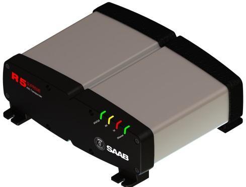
43 5 OPERATION 5.1 General usage The system can be fully operated using the R5 SUPREME CDU. The CDU is operated using the touch sensitive screen, or the backlit keypad. Some ECDIS systems may also allow for normal AIS usage. Apart from observing received AIS targets, normal interfacing with the system involves: Updating voyage related parameters Updating navigational status Verifying alarms Sending/receiving text messages. The CDU Front hatch covers an integrated AIS Pilot Plug connector. This hatch can be locked shut if needed. We recommend a flat tip mm screwdriver for locking/unlocking the hatch. 5.2 LED s on R5 SUPREME Transponder 1 - STATUS LED (multi-colour) Constant green when the transponder is operating and no alarms are active. Constant red if there is an active alarm. Flashing red if there is an unacknowledged alarm. 2 - RX LED (yellow) OPERATION , A3 Page 43
44 Flashes yellow when the transponder receives a message on the VHF link. 3 - TX LED (red) Flashes red when the transponder transmits a message on the VHF link. 4 - Ethernet LED (green) Constant green when an Ethernet cable is connected Flashes green when data is transferred. 5.3 LED s and Controls on R5 SUPREME CDU This section describes the controls and status LED s on the front of the R5 SUPREME CDU. 1 - STATUS LED (multi-colour) Constant green when the transponder is operating and no alarms are active Constant red if there is an active alarm Flashing red if there is an unacknowledged alarm 2 - RAIM LED (multi-colour) Not used in standard R5 SUPREME AIS System. Only used in Navigation System enabled installations. 3 - MODE LED (multi-colour) Not used in standard R5 SUPREME AIS System. May be used in other product variants, see product variant specific documentation. 4 - LIGHT SENSOR Can be used to automatically dim the backlight of the display, see Visual Settings 5 - ARROW KEYPAD and ENTER OPERATION , A3 Page 44
45 The easiest way to navigate in menus, lists and edit fields in the R5 SUPREME CDU is by using the touch interface. However, the arrow keypad and ENTER button can also be used to control the R5 SUPREME CDU in e.g. rough seas. The arrow keypad (< > and ) is used to navigate in menus, lists and edit fields. The centre button of the keypad is an ENTER button which is used to select the highlighted choice in a menu, list or edit control. 6 - PWR The power button on the R5 SUPREME CDU is used to turn off the display and can also be used to quickly change the settings for backlight of LCD, buttons and LEDs. A quick press of the PWR button will turn off all backlight but the R5 SUPREME CDU will still be running. If there is an active, unacknowledged alarm in the system, the STATUS LED will still be blinking red. Otherwise all LED s will be turned off. If the PWR button is pressed for more than two seconds, a Power Down Menu will appear. Here it is possible to power off the R5 SUPREME CDU completely or to quickly change the backlight percentage for the LCD, LEDs and buttons if Dimming Mode is set to Manual (see section for information about Dimming Mode parameter). 7 - OPT 8 - MOB 9 - ESC Figure 8 Power Down Menu If the PWR button is pressed for more than fifteen seconds, the CDU will perform a hard reboot. This button is an Option key which is only active in some of the views. When pressed, it gives the user a list of options that can be performed on the highlighted item. In screens with parameters, the OPT button can be used to set the parameter to default value. Not used in the plain R5 SUPREME AIS System. Only available in Navigation System enabled installation. Used to return to previous screen or to cancel an edit change of a data field Change Settings of a Parameter Several of the views in the R5 SUPREME CDU contain parameters that can be edited. To edit a parameter, click on it using the touch interface. A virtual keyboard will appear where it is possible to enter data. Click on the enter button of the virtual keyboard when the data input is done. To save all the changes made in the current view, press the Save button in the lower right corner of the screen. OPERATION , A3 Page 45


46 Figure 9 Example of a parameter view It is also possible to use buttons on the front of the R5 SUPREME CDU to select and change a parameter. Use the ARROW KEYPAD to select a parameter, the currently selected parameter will be marked with an orange rectangle (see figure above). Press ENTER to popup the virtual keyboard. Use the ARROW KEYPAD to highlight the desired character and press ENTER to select it. Navigate to enter button of the virtual keyboard and press ENTER when done. Figure 10 Example of virtual keyboards OPERATION , A3 Page 46
47 5.4 Menu Structure Tree view Main menu Maintenance Voyage AIS Status Messages Installation Test Ais Voyage Operational Mode Status List Long Range Msg Communication Test Own ship data View Raw Data Persons on Board Restore Config Plot SW/HW Info AIS Messages System Update Target List Alarm List Update CDU SW AIS Status Update Transponder SW AIS Internal GPS Status Update Licenses VHF Status Configuration Non Functional Time Alarm Interface Misc Interfaces Port Rates System Setup Network Transponder Settings Select Transponder Own CDU Settings Display Visual Settings Calibrate Display Time Units Sound CDU Password AIS Long Range Ship Dimensions Ship Static Display Parameters Password VHF Radio Regional Areas Edit Area View Area New Area Long Range Broadcast OPERATION , A3 Page 47


48 5.4.1 Navigating in Menus To navigate in the R5 SUPREME CDU menus, simply press the menu button corresponding to the desired view using the touch interface, or use the ARROW KEYPAD buttons < > and to navigate between the view buttons. The currently selected button will be marked with an orange outline and orange text. Press the ENTER button to enter the currently selected view. In the lower left corner of a view there is also a Back button to quickly go back to previous view and a Main button to go directly to the Main Menu view. Figure 11 Main Menu Figure 12 AIS Menu 5.5 Alarm and Alert Pop-ups The R5 SUPREME AIS System features alarm and alert pop-ups that can appear any time during operation. To acknowledge an alarm or alert message, click the ACK button using the touch screen or press ENTER. An example of an alarm message is shown below. Figure 13 Alarm Popup 5.6 Status Bar The top of the screen of the R5 SUPREME CDU always displays a summary of the system s status. See illustration below. Current time Status icons Current position OPERATION , A3 Page 48 Current synchronization state
49 If a valid navigation position is available, it is displayed to the left. The status icons are displayed in the middle and the current time is shown to the right. Time is either UTC or local (LOC). Beneath the current time there is also information about the transponder s synchronization state. The synchronization state can be: UTC Direct This is the normal state where the R5 SUPREME Transponder gets the UTC time from its own internal GPS receiver. Indirect Synchronization The R5 SUPREME Transponder is synchronizing based on receipt of data from other AIS transmitters. NOTE: It is possible to be in Indirect Synchronization but still have a valid position in the upper left corner of the status bar. The position information may be from an external GPS sensor, but UTC Direct synchronization can only be taken from the internal GPS receiver. 5.7 Status Icons The status icons that can be displayed are: Unread message (safety related message, text message or RTA) Unread Long Range message (automatic reply) Unread Long Range message (manual reply) Active alarms 1W mode (Indicates 1 Watt TX mode for Tankers is enabled.) See NOTE below for details. Silent Mode activated, either with Tx Mode parameter or silent switch. Navigational status, being one of: Navigational status is undefined At anchor or moored Under way using engine Navigational status is one of: Not under command, Restricted manoeuvrability, Constrained by her draught, Aground, Engaged in fishing, Under way sailing, Reserved for future use. NOTE: The transponder will automatically engage 1W mode when the following conditions are met: Ship type = Tanker, Nav Status = Moored and SOG <= 3 knots, otherwise 1W mode will be automatically disengaged. The Tanker 1W mode is fully automatic and cannot be disengaged by other external control. 5.8 View Remote Ship Information The R5 SUPREME AIS System will power up in Target List view. This view is accessed from Main Menu AIS Target List. OPERATION , A3 Page 49
, range (RNG), bearing (BRG) and time since last report was received (Age) for each AIS target received by the system.")
 and press ENTER. It is now possible to use the buttons to select the desired target in list.")
50 The Target List view displays a list of all AIS targets received on the VHF link. The list includes MMSI or ship s name (Ship ID), range (RNG), bearing (BRG) and time since last report was received (Age) for each AIS target received by the system. Figure 14 Target List For extended information about a target in the list, select the desired target in the list and then press the Extended Info button. When using the ARROW KEYPAD, use the buttons to select the target list (marked with an orange frame) and press ENTER. It is now possible to use the buttons to select the desired target in list. The press ESC and use the ARROW KEYPAD to navigate to the Extended Info button. Press ENTER to ent br the Extended Information view. The Extended Information view includes static, dynamic and voyage related data for the selected target. Press the button Next Page to switch between the pages of extended information. Figure 15 Extended Info Press Back button in the lower left corner to return to Target List view. 5.9 View Plot of Targets The location of targets relative to your own ship is visualized in the Plot view. The view is accessed from the Main Menu AIS Plot. OPERATION , A3 Page 50

51 Figure 16 Target Plot For extended information about a target select it in the plot and press the Extended Info button in the lower right corner. The own ship target is displayed as a T shaped symbol. Class B targets are indicated by a B appended to the target icon and Inland targets are indicated by either an I or by a blue sign symbol appended to the target View Transmitted Own Ship Information The information transmitted by the R5 SUPREME Transponder on the VHF link is viewed in the Own Ship Data view. This view is accessed from Main Menu AIS Own Ship Data and includes the static, dynamic and voyage related data actually sent by the R5 SUPREME Transponder. The view reflects the contents of the last transmitted AIS messages, thus there may be some delay from the time the parameters are changed until they are displayed in the Own Ship Data view. Figure 17 Transmitted Own Ship Data 5.11 Enter and Read Voyage Related Information Voyage related information (for transmit via AIS) is displayed in the AIS Voyage view. The view is accessed from Main Menu AIS VoyageAIS Voyage. Voyage related data includes destination, estimated time of arrival (ETA) and number of people aboard. OPERATION , A3 Page 51
 and Text Messages Safety related messages (SRMs) and text messages can be sent to specific targets (addressed messages) or broadcast to all targets.")
52 Figure 18 AIS Voyage 5.12 Handling Safety Related Messages (SRM) and Text Messages Safety related messages (SRMs) and text messages can be sent to specific targets (addressed messages) or broadcast to all targets. The Inbox, Outbox and Send views for SRMs and text messages can be accessed from Main MenuMessagesAIS Messages Read Received Messages Figure 19 - AIS Messages Received messages can be accessed in the Inbox view. Unread SRMs and text messages are indicated with an envelope icon in the status bar. In the Inbox view unread messages are marked with a closed envelope while read messages are marked with an open envelope. OPERATION , A3 Page 52


53 Figure 20 AIS Message Inbox Send SRMs and Text Messages SRMs are composed and sent in the Send view accessed from Main Menu Messages AIS Messages Send. To write a message, click in the text edit area to the left or use the ARROW KEYPAD to mark the text area and press ENTER. This will show the virtual keyboard where the message can be entered. Click on the ENTER button of the virtual keyboard when done. Figure 21 Virtual Keyboard Figure 22 AIS Message Send view OPERATION , A3 Page 53
 to another vessel.")

54 Sent messages can be viewed in the Outbox view accessed from Main Menu Messages AIS Messages Outbox Send Persons On Board Figure 23 AIS Message Outbox In the Persons On Board view it is possible to send information about number of persons on board (PoB) to another vessel. The PoB message can be sent as either addressed or broadcast. The information sent in the messages is automatically filled in by the R5 SUPREME AIS System depending on the voyage configuration made in Main MenuVoyageAIS Voyage Long Range Interrogations Figure 24 Persons On Board An AIS transponder can receive long range interrogation messages to poll for certain information. A received interrogation message is indicated by a LR icon in the status bar. If the Long Range Reply Mode parameter has been configured to Auto, the R5 SUPREME Transponder will automatically send a response to the interrogation. If the Long Range Reply Mode parameter is set to Manual, the operator must send a response or refusal from the Long Range Message view accessed from Main Menu Messages Long Range. For more information about the Reply Mode parameter and Long Range filter settings, see section OPERATION , A3 Page 54

55 Figure 25 Long Range To send a reply or refusal to the interrogation or to delete an interrogation from the message list, click on the message in the list view to mark it and then click on one of the buttons Send Reply, Refuse Reply or Delete. When using the ARROW KEYPAD, use the buttons to navigate to the message list and press ENTER. Mark the desired interrogation by again using and then press ESC button to be able to navigate to the desired button using the ARROW KEYPAD (, < >). Press ENTER when the desired button is marked with orange frame and orange text (see Send Reply button in picture above). The Long Range view uses the following symbols to indicate the status of a request or reply message:? The information is requested by the sender X The information is available and provided! The information requested is refused 5.15 Regional Areas Regional Area messages are transmitted from shore based AIS Base Stations by local authorities to control AIS VHF settings of AIS transponders within a defined area. The transponder will store up to eight different areas. An area will timeout and be deleted 24 hours after it was last received, or if the distance to the area becomes greater than 120 NM. All regional areas that are stored in the R5 SUPREME Transponder can be viewed in the Regional Areas view which is accessed from Main Menu Maintenance Configuration AIS VHF Radio Regional Areas. The list shows the north east and south west corners of the areas. The area is marked with green colour if it is in use by the R5 SUPREME Transponder. To view the settings of an area or to edit an existing area, mark the area in the list and click on the View Area or Edit Area button. When using the ARROW KEYPAD, mark the area list and then press ENTER to be able to select the desired area with. When the correct area is selected, press ESC and use the ARROW KEYPAD to navigate to the desired button. It is possible to manually create and edit regional areas in the system. It is not recommended to modify anything in this view unless instructed to do so by the authorities or for testing in a controlled environment. OPERATION , A3 Page 55


56 Figure 26 Regional Areas 5.16 Alarms All currently active and enabled alarms are shown in the Alarm List view that can be accessed from Main Menu Status Alarm List or by clicking on the alarm indication in the status bar. As default, only alarms that are configured as Enabled will be shown in the list. It is possible to also show disabled active alarms by pressing the button Show All Alarms. For a list of all alarms, see chapter Status List Figure 27 - Alarms Current status indications are listed in the Status List view that can be accessed from Main Menu Status Status List. The different status indications that can occur are listed in chapter 8.8. OPERATION , A3 Page 56

57 Figure 28 - Status List 5.18 Non Functional Time This view displays information about times when the R5 SUPREME Transponder has been turned off or for some other reason has not been transmitting for more than 15 minutes. The view is accessed from Main Menu Status AIS Non Functional Time AIS Internal GPS Status Figure 29 - Non Functional Time This view displays the satellites received by the R5 SUPREME Transponder internal GPS receiver. The list is sorted by the satellites ID (PRN number) and shows elevation, azimuth and signal to noise ratio (SNR) for each satellite. The view also displays the total number of satellites in view and the total number of satellites used in the position calculation reported by GGA sentence. OPERATION , A3 Page 57

58 Figure 30 AIS Internal GPS Status 5.20 View Raw Data This view displays the incoming data on the selected serial port. It is also possible to pause the data on the screen by pressing the Freeze button. The View Raw Data view can be a helpful tool when trouble shooting the system to see what sensor input is actually received on each port. The view can be accessed from Main Menu Status View Raw Data SW/HW Info Figure 31 - View Raw Data This view displays the software and hardware revisions for the R5 SUPREME AIS System and is accessed from Main Menu Status SW/HW Info. This information should always be provided when in contact with Saab TransponderTech support. OPERATION , A3 Page 58


59 Figure 32 - SW/HW Info 5.22 VHF Status The VHF Status view shows the currently used settings. Channel number, frequency, power and operation mode are displayed for each VHF transceiver in the R5 SUPREME Transponder. This information is useful when troubleshooting to make sure that the R5 SUPREME Transponder uses the expected VHF radio settings. If e.g. a regional area is set and in use, this will affect the information shown in the VHF Status view Communication Test Figure 33 - VHF Status When installing the R5 SUPREME AIS System, or when performing annual testing, a communication test shall be done to ensure that other transponder systems can receive the R5 SUPREME Transponder s transmissions. This can be done from the Communication Test view accessed from Main Menu Maintenance Communication Test. When entering the Communication Test view a suggested target with a suitable range (between 15 NM and 25 NM) will be selected in the MMSI parameter field if such a target has been received by the R5 SUPREME AIS System. It is however possible to select a different target for the communication test. To start the test, click on the Send button in lower right corner. A popup with the result of the communication test will appear if a reply is received or if no reply has been received within 15 seconds. OPERATION , A3 Page 59


60 Figure 34 - Communication Test 5.24 Update Software The software of the R5 SUPREME CDU is easy upgradable via the USB Host interface located behind the front hatch of the R5 SUPREME CDU. To perform a software update, follow the instructions in the Update Software view which can be accessed from Main Menu Maintenance Update Software. For more information about the upgrade procedure, refer to chapter 6, Software Upgrade Restore Configuration Figure 35 - Update Software All config parameters described in section 4.3 Configuration Parameters can be set to default values from the Restore Config view which can be accessed from Main Menu Maintenance Restore Config. NOTE: The MMSI parameter will also be reset to zero and therefore the transponder will stop transmitting and the alarm Tx Malfunction will become active. OPERATION , A3 Page 60

61 Figure 36 Restore Config OPERATION , A3 Page 61
62 6 SOFTWARE UPGRADE Note: After updating the software add a sticker stating the new software version close to the product label. After replacing the CDU or Transponder unit with a new unit, it may be necessary to make a software upgrade to make sure there are no software compatibility issues. It is possible to upgrade the software in the Transponder unit and the CDU unit. Make sure to carefully read the release notes for the software upgrade package first. The Transponder can be upgraded over Ethernet via the R5 CDU USB port or from the R5 AIS Junction box USB port. 6.1 Upgrade Software in R5 SUPREME Transponder via Junction Box. The R5 SUPREME Transponder can be upgraded through the USB host interface located in the R5 AIS Junction Box. To upgrade the software in the R5 SUPREME Transponder, perform the following steps: Unzip the R5 SUPREME Transponder upgrade package in the root folder of an USB memory stick (must be FAT32 formatted). There should now be a folder called swload in the USB root folder. Insert the USB memory stick in the USB host interface in the R5 AIS Junction Box. Make sure that the R5 SUPREME Transponder s 26-pin I/O port is connected to the R5 Junction Box. Hold down the SW-LOAD -button in the R5 AIS Junction Box. The R5 SUPREME Transponder will reboot and start the software upgrade. The SW-LOAD -button must be held down until the transponder STATUS LED is lit green and the transponder Rx LED is lit yellow. 6.2 Upgrade Software in R5 SUPREME Transponder via CDU It is also possible to upgrade the R5 SUPREME Transponder via Ethernet interface by using the R5 SUPREME CDU. Perform the following steps to initiate the transponder software upgrade from the R5 SUPREME CDU: Unzip the R5 SUPREME Transponder upgrade package in the root folder of an USB memory stick (must be FAT32 formatted). There should now be a folder called swload in the USB root folder. Insert the USB memory stick in the USB host interface in the USB port located behind the front hatch of the R5 SUPREME CDU. Make sure that the R5 SUPREME CDU and R5 SUPREME Transponder communicates with each other via Ethernet. Several R5 Transponders may be available on the network. The currently selected transponder is marked with green colour in the Select Transponder view which can be accessed from Main Menu Maintenance Configuration Interface Network Select Transponder. SOFTWARE UPGRADE , A3 Page 62


63 Figure 37 Select Transponder Start the upgrade procedure by following the on screen instructions in the Update Transponder SW view which can be accessed from Main Menu Maintenance Update Transponder SW. Figure 38 Update Transponder SW The R5 SUPREME Transponder will reboot when the new software has been loaded so the connection will temporarily be lost. When the transponder has rebooted with the new software and connection is established again, the following view will be shown, indicating that the upgrade is complete: Figure 39 Update Transponder SW, Complete SOFTWARE UPGRADE , A3 Page 63
64 6.3 Upgrade Software in R5 SUPREME CDU The R5 SUPREME CDU is easy upgradable through the USB host interface located behind the front hatch. To upgrade the software in the R5 SUPREME CDU, perform the following steps: Unzip the R5 SUPREME CDU upgrade package in the root folder of an USB memory stick (must be FAT32 formatted). There should now be a folder called cduswload in the USB root folder. Insert the USB memory stick in the USB host interface located behind the front hatch. Hold down the Down Arrow -button on the front of the R5 SUPREME CDU and reboot the system. The Down Arrow -button must be held down until the RAIM LED is blinking yellow. The software upgrade is complete when the STATUS LED is lit green. The R5 SUPREME CDU will automatically reboot after 3 seconds. Check that correct SW has been loaded in the SW/HW Info view which can be accessed through Main Menu Status SW/HW Info. If the upgrade process fails, The STATUS LED will be lit red and one of the RAIM LED or MODE LED starts blinking. Should this happen, hold down the Down Arrow -button and reboot the R5 SUPREME CDU to try again. The software upgrade can also be initiated from the Update Software view in the R5 SUPREME CDU. Refer to chapter 5.25 Update Software for more information. MODE LED RAIM LED STATUS Upgrade mode started YELLOW GREEN Upgrade in progress Blinking YELLOW Upgrade complete (automatic reboot after 3 sec) Error: USB Not Found Error: No SW found on USB Blinking YELLOW 0.5Hz Blinking YELLOW 4Hz GREEN RED RED Error: Flash erase failed Error: Flash write failed Blinking RED 0.5 Hz Blinking RED 4 Hz RED RED Table 10 CDU LED Indicators during Software Upgrade SOFTWARE UPGRADE , A3 Page 64
65 7 TECHNINCAL SPECIFICATIONS 7.1 R5 SUPREME Transponder Physical Dimensions: Weight: Height: 77 mm Width: 227 mm Depth: 192 mm 2.05 kg Electrical Input Voltage: Power Consumption: 24 VDC 20 W (60 W peak) Environmental Temperature: -15 C to +55 C (Operational) -30 C to +80 C (Storage) Vibrations: IEC ed. 4 EMC: IEC ed. 4 Radio Type Approval: IEC ed. 1 Compass Safe Distance: 65 cm (for standard magnetic compass) 40 cm (for steering magnetic compass) VHF Transceiver Receivers: Transmitter: Channel bandwidth: MHz (TDMA) MHz fixed (DSC, Channel 70) MHz 25 khz Output Power: High: 12,5 W Low: 1W Tanker 1W Mode : 1W VHF antenna connector: BNC-Female Antenna Input Impedance: 50 ohm TECHNINCAL SPECIFICATIONS , A3 Page 65
66 7.1.5 Internal GPS Receiver Type: Update rate: Accuracy: Antenna feeding: GPS Antenna connector: GPS L1, C/A Code, 50 Channels 2 Hz < 2.5 m (GPS, CEP, 50%, 24 hours static) < 2.0 m (SBAS, CEP, 50% 24 hours static) 5 VDC TNC-Female Antenna Input Impedance: 50 ohm AIS Alarm Relay Max switching current: Max switching voltage: Max switching power: 0,1 5 A 30 VDC 150 W 7.2 R5 SUPREME CDU Physical Dimensions: Weight: Dimensions (incl. gimbal mount) Weight (incl. gimbal mount): Height: 140 mm Width: 255 mm Depth: 84 mm 1.6 kg Height: 170 mm Width: 295 mm Depth: 84 mm 1.75 kg Electrical Input Voltage: Power Consumption: VDC 13 W Environmental Temperature: -15 C to +55 C (Operational) TECHNINCAL SPECIFICATIONS , A3 Page 66
67 -30 C to +80 C (Storage) Vibrations and EMC: IEC ed. 4 Compass Safe Distance: 75 cm (for standard magnetic compass) 50 cm (for steering magnetic compass) 7.1 R5 AIS Junction Box Physical Dimensions: Weight: Height: 72 mm Width: 273 mm Depth: 149 mm 0.75 kg Electrical Input Voltage: Power Consumption: 24 VDC 13 W Environmental Temperature: -15 C to +55 C (Operational) -30 C to +80 C (Storage) Vibrations and EMC: IEC ed. 4 Compass Safe Distance: 75 cm (for standard magnetic compass) 50 cm (for steering magnetic compass) V TECHNINCAL SPECIFICATIONS , A3 Page 67
68 8 TROUBLESHOOTING One of the basic ideas with troubleshooting is to solve a supposed problem on site instead of immediately sending the suspected part for a costly repair. Solving a supposed problem would in this aspect mean both to rectify the real problem, but it could also mean that the suspected part is confirmed to be working or not-working. Historically, many of the parts sent to Saab TransponderTech for repair have in fact been confirmed working instead. Another common scenario is that the equipment has faulty I/O settings or other erroneous configurations, easy to fix on site. A proper troubleshooting would ideally prevent those unnecessary returns of fully functional equipment. There are numerous ways to troubleshoot a transponder installation, much dependant on the skill and experience level of the troubleshooter. The preferred approach may probably also differ between different individuals, and there is no such thing as right or wrong. This chapter is not intended to be a step by step troubleshooting instruction, but instead offer a toolbox with some different techniques on how to troubleshoot the R5 SUPREME AIS System. 8.1 Troubleshooting Prerequisites A transponders operating environment may naturally differ widely, ranging from small high-speed RIB s to very large SOLAS tankers, military aircraft carriers and even submarines. The diversity of installation environments will of course have impact on the complexity of the troubleshooting, but it is always advisable to start with minimizing all possible interference sources in order to simplify the troubleshooting. Disconnect other NMEA equipment from the R5 (ECDIS, RADAR, NAV, etc.) Switch off other emission sources (RADAR, SATCOM, VHF, etc.) We strongly encourage to always use the latest software available for the R5 SUPREME System. It may contain bug-fixes and other improvements solving already known issues. Always check existing release notes to see if your problem is to be found. 8.2 Troubleshooting with the Front Panel LED s of the Transponder It is very fast and effective to use the LED s to verify the status of the R5 SUPREME Transponder. This should always be the first step in the troubleshooting STATUS LED (multi-colored) - The STATUS LED is constantly lit green when the transponder is operating and no alarms are active. - The STATUS LED is constantly lit red if there are one or more acknowledged active alarms in the transponder, but no unacknowledged alarms. Refer to chapter 8.3 for interpretation of the alarms. - The STATUS LED is flashing red if there are one or more unacknowledged alarms in the transponder. Refer to chapter 8.3 for interpretation of the alarms. If neither color are lit, nor flashing, then check the power supply and make sure that: The voltage is correct and stable The polarity is correct and not switched The available current is sufficient for start up and transmission The external fuse is functional TROUBLESHOOTING , A3 Page 68
69 The power cable is undamaged The power connector is properly connected and secured RX LED (yellow) The RX LED is flashing yellow when the transponder is receiving a message from the VDL. This can be intermittently. If there is verified traffic on the VDL and the RX LED still is dark, then check the alarm list for any active alarms. Refer to chapter 8.3 for interpretation of the alarms. Lack of reception may be an indication of a VHF antenna problem or connectivity issues. Check the installation for problems TX LED (red) The TX LED is flashing red when the transponder is transmitting a message to the VDL. The transmission interval is between seconds. Refer to chapter 8.5. If the TX LED is completely dark, then check so that the transmission is not switched off either through an active regional area or by the Tx Mode parameter. It is possible to check the status on each transceiver in the VHF Status view described in section If the transmission is activated and there still is no red flashing, then check the alarm list for any active alarms. Refer to chapter 8.3 for interpretation of the alarms. 8.3 Troubleshooting with Alarm Messages The R5 SUPREME AIS System constantly monitors itself for failures, abnormal conditions and other important parameters. Some of the monitoring trigger alarms and those alarms are excellent aids in the troubleshooting process. An active alarm can have two states, unacknowledged or acknowledged. The state of an alarm will affect the STATUS LED on both the R5 SUPREME Transponder and the R5 SUPREME CDU. Refer to chapter A new alarm (unacknowledged) will raise a pop-up window that needs to be acknowledged by the user. The active alarms can be found in the alarm view. Refer to chapter All active alarms are outputted on all the serial interface ports of the R5 SUPREME Transponder every 30 seconds. The alarm status can for example be used in interfacing ECDIS systems or centralized alarm systems. The alarms can also be monitored or recorded for troubleshooting purposes by for example a terminal application. The status of an alarm can be identified by two letters in the alarm sentence, A and V. The alarm sentence is constructed as: $AIALR,hhmmss.ss,xxx,A,A,c-c, where: hhmmss.ss = Time (UTC) of alarm condition change xxx = Unique alarm identifier A = Alarm condition (A = Active, V = Inactive) A = Alarm s acknowledge state, A = acknowledged, V = unacknowledged c-c = Alarm s description text $AIALR,hhmmss.ss,xxx,V,A,c-c: Tx malfunction: Alarm is Inactive $AIALR,hhmmss.ss,xxx,V,V,c-c: Tx malfunction: Alarm is Inactive $AIALR,hhmmss.ss,xxx,A,A,c-c: Tx malfunction: Alarm is Active and Acknowledged $AIALR,hhmmss.ss,xxx,A,V,c-c: Tx malfunction: Alarm is Active and Unacknowledged The alarms that can occur in the R5 SUPREME AIS System are listed below: TROUBLESHOOTING , A3 Page 69
70 8.3.1 AIS: Tx Malfunction (ID 001) A Tx Malfunction alarm is generated if there is a malfunction in the radio transmitter hardware or if the antenna VSWR exceeds an allowed ratio. If the radio transmitter returns to normal operation or if VSWR returns to a value below the allowed threshold, the alarm is cleared. The Tx Malfunction alarm is also generated when the MMSI is configured to 0, in which case the R5 SUPREME Transponder will not transmit AIS: Antenna VSWR Exceeds limit (ID 002) The VSWR (Voltage Standing Wave Ratio) of the antenna is checked for every transmission and if it exceeds a given ratio then a VSWR alarm is generated. If the VSWR goes below the allowed threshold, the alarm is cleared AIS: Rx Ch A Malfunction (ID 003) AIS: Rx Ch B Malfunction (ID 004) AIS: Rx Ch C Malfunction (ID 005) The radio receivers are continuously monitored and if any part of the receivers hardware should malfunction, an Rx Malfunction alarm is generated for that receiver. If the radio receiver returns to normal operation, the alarm is cleared AIS: General Failure (ID 006) This alarm is generated if the R5 SUPREME Transponder fails to initiate the radio or if a severe hardware failure has occurred. If this alarm occurs, contact your retailer AIS: UTC Sync Invalid (ID 007) This alarm is generated when the R5 SUPREME Transponder loses UTC direct synchronization (cannot synchronize from internal GPS receiver) AIS: MKD connection lost (ID 008) This alarm is active if the R5 SUPREME Transponder has lost connection with the R5 SUPREME CDU. If this alarm occurs, check the Ethernet connection and the network settings AIS: Internal/External GNSS position mismatch (ID 009) This alarm is generated if the difference between the internal and external GNSS position is more than 100 m for more than 15 minutes AIS: NavStatus incorrect (ID 010) This alarm is generated if the navigational status is incorrect. If e.g. the navigational status is set to At Anchor but the ship is moving faster than 3 knots, the NavStatus incorrect alarm will become active AIS: Heading sensor offset (ID 011) This alarm is active when SOG (Speed Over Ground) is greater than 5 kn and the difference between COG (Course Over Ground) and HDT (True Heading) is greater than 45 for 5 min AIS: Active AIS SART (ID 014) This alarm is generated when the R5 SUPREME Transponder has received an active AIS SART position report AIS: External EPFS Lost (ID 025) This alarm is generated if the position from the external Electronic Position Fixing System is invalid (i.e. no external GNSS). Due to the fallback arrangement for the positioning sensor this TROUBLESHOOTING , A3 Page 70
71 alarm can be inactive up to 30 seconds (during which the internal GNSS is used) before the alarm is activated AIS: No Sensor Position In Use (ID 026) This alarm is active if the R5 SUPREME Transponder does not have a valid position (latitude/longitude) from any sensor AIS: No Valid SOG Information (ID 029) / No Valid COG Information (ID 030) These alarms are active if the R5 SUPREME Transponder does not have a valid SOG (Speed Over Ground) or a valid COG (Course Over Ground) from any sensor. The SOG and COG is based on the speed log (if external GNSS is used and a valid heading is available) or the GNSS currently in use AIS: Heading Lost/Invalid (ID 032) This alarm is generated if either the heading information is lost/invalid (from external sensors) or if the heading is undefined AIS: No Valid ROT Information (ID 035) This alarm is active if ROT (Rate Of Turn) is undefined or if no valid ROT information is available from external sensor or internal calculations AIS: CDU Lost Connection To Transponder This alarm is active if the R5 SUPREME CDU has lost connection with the R5 SUPREME Transponder. If this alarm occurs, check the Ethernet connection and the network settings. 8.4 Troubleshooting via the CDU There is a lot of information and data accessible via the CDU that can be useful for troubleshooting, and that can help finding a presumed problem. The following items are just a few examples of what to look at Transmitted Own Ship Data View When the transponder transmits data on the VDL, it also simultaneously outputs this data on all the serial ports. This information is displayed in the Own Ship Data view. Figure 40 Transmitted Own Ship Data TROUBLESHOOTING , A3 Page 71

72 8.4.2 Target List The target list is primarily useful when analyzing the receiving functionality. The propagation characteristics of VHF radio frequencies are close to line of sight. A harsh radio environment, reflections in cables, connectors or the antenna will shorten the effective range Time in Status Bar Figure 41 Target List The time (UTC or LOC) in the upper right corner of the display is provided by the transponder. If the time is not correct, the transponders internal GPS does not have a position fix. This will also be indicated by the alarm UTC sync invalid. This problem is normally caused by a GPSantenna failure or damaged antenna cables. This problem may also be caused by interference from radio equipment on-board View Raw Data The View Raw Data view can be used to see received data on the ports of the R5 SUPREME AIS System. It is useful for troubleshooting to make sure that connected sensors provide correct data to the system. The View Port parameter determines from which port the data displayed in the view are taken. It is possible to pause the view by pressing the Freeze button. All data that is received while the view is paused will not be displayed in the view. Figure 42 View Raw Data TROUBLESHOOTING , A3 Page 72
73 8.4.5 Status List The status list view is used to display status indications that are stored in the transponder. The indications are created when an important event has occurred in the transponder. Time of occurrence and status indication text are shown in the view. A list of all possible indications can be found in section 8.8 Indication Messages. Figure 43 Status List 8.5 Reporting Intervals for Class A Transponders The different information types sent by the R5 SUPREME AIS System are valid for different time periods and therefore they need different update intervals. These update intervals are defined in the AIS standard (ITU-R M ) and should be applied by all transponders. There are however some exceptions from this, which can be found in the standard. Class B transponders have for example different intervals than the Class A transponder. All this needs to be taken in consideration while troubleshooting thus it affects the anticipated behaviour of a transponder. Information type / Condition Static Information Voyage related information Nominal reporting interval 6 min, on amendment, on request 6 min, on amendment, on request Dynamic information (See conditions below) - Ship at anchor or moored and not moving faster than 3 knots 3 minutes - Ship at anchor or moored and moving faster than 3 knots 10 seconds - Ship 0-14 knots 10 seconds - Ship 0-14 knots and changing course 3 1/3 seconds - Ship knots 6 seconds TROUBLESHOOTING , A3 Page 73
74 - Ship knots and changing course 2 seconds - Ship > 23 knots 2 seconds - Ship > 23 knots and changing course 2 seconds Table 11 Reporting Intervals 8.6 F.A.Q I cannot see the vessel on the Internet AIS service Websites providing AIS services like e.g. does not cover all the seas of the world, but only specific coastal areas where AIS receivers have been installed and that upload the data to the websites. The vessel must be in reception range of these AIS receivers to show up on the Internet AIS service I can see the other vessel, but they do not see my vessel There are several reasons why this might happen. The first thing to check is if the R5 SUPREME Transponder is transmitting at all or if is transmitting in low power mode. In VHF Status view described in section 5.23 it is possible to check the status on all R5 SUPREME Transponder s VHF transceivers. Make sure that correct channels and power mode are used. There might be a regional area set in the transponder that changes the operating mode of the R5 SUPREME Transponder. Regional areas are listed in the Regional Area view (see section 5.16). The MMSI must also be configured in order for the R5 SURPEME Transponder to transmit. If the MMSI is zero, the R5 SUPREME Transponder will be silent. Another possibility is that the other vessels transponder requires a shorter reception range in order to receive the R5 SUPREME Transponder s transmissions. In the Target List view and the Plot view it is possible to see the range and bearing to other vessels The VHF range seems to be short As a rule of thumb, the VHF range is equal to line of sight from the antenna position, which means that the higher the antenna is installed, the longer the range will be. It is also important to follow the guide lines for an antenna installation as thoroughly as possible. Section 3.10 Mount the VHF Antenna describes how to best install the VHF antenna I can only receive a few GPS satellites The position of the GPS antenna is of high importance to optimize the GPS reception. Follow the guide lines of GPS antenna installation described in chapter 3.8 Mount the GPS Antenna as thoroughly as possible. If the ship is close to a harbour or shore with high structures or travelling in an area with high terrain, the GPS reception might be worse. The GPS antenna must be installed where it has a clear view of the sky. The objective is to see the horizon freely through 360 degrees with a vertical observation of 5 to 90 degrees above the horizon. The GPS antenna cable should also be as short as possible and with 50 Ω impedance. A very long antenna cable or faulty impedance can heavily reduce the GPS reception. TROUBLESHOOTING , A3 Page 74
75 8.7 Contacting Support The primary source for support and RMA issues should for end customers be the dealer where the equipment was purchased in the first place. Another option is to contact one of our OEM partners or affiliate service stations and request help. An updated list with our dealers, OEM partners and service stations can be found at our website, listed under the corresponding product. It is also possible to contact Saab TransponderTech s technical support if this is preferred. We recommend contacting us via at support.transpondetech@saabgroup.com for most accurate and detailed help. If the situation is very urgent then it is of course also possible to call us at normal Swedish workdays and working hours. Telephone Before contacting support, always check the following information and include it in the first , or have it ready at the phone call: - All the information provided by the SW/HW Info view which can be accessed from Main MenuStatusSW/HW Info. - Detailed fault description 8.8 Indication Messages The indication messages, with identity and type information, are listed below: ID Type Message text 021 Status External DGNSS in use 022 Status External GNSS in use 023 Status Internal DGNSS in use (beacon) 024 Status Internal DGNSS in use (msg 17) 025 Status Internal GNSS in use 027 Status External SOG/COG in use 028 Status Internal SOG/COG in use 031 Status Heading valid 033 Status Rate of Turn Indicator in use 034 Status Other ROT source in use 036 Event Channel management parameters changed 056 Event Channel management zone memory changed 061 Status Enter semaphore mode 062 Event Leave semaphore mode 063 Event NVM Checksum errors 064 Event RATDMA overflow 066 Status Tanker Low VHF Power Mode 067 Status Beacon correction received 068 Status VDL correction received 069 Status No correction received TROUBLESHOOTING , A3 Page 75
76 8.9 Long Range Definitions A = Ship s name, call sign, and IMO number B = Date and time of message composition C = Position E = Course over ground (COG) F = Speed over ground (SOG) I = Destination and Estimated Time of Arrival (ETA) O = Draught P = Ship/Cargo U = Ship s length, breadth, type W= Persons on board TROUBLESHOOTING , A3 Page 76
77 9 INTERPRETATION OF INPUT SENTENCES All interface ports accepts the full set of input listed below sentences, except the sentences listed in section that are unique to the Long Range interface port. The protocol of the serial input sentences shall be compliant to IEC Ed.4 ( ) for maximum interoperability. 9.1 GPS and Sensor Input Sentences DTM - Datum Reference If local code is other than WGS84, then the positions report from that port is discarded. $--DTM,ccc,a,x.x,a,x.x,a,x.x,ccc Field Format Name Comment 1 --DTM Sentence Id Used 2 ccc Local Datum Code Interpret if it s WGS84 or not 3 A Local Datum Subdivision Code Ignored 4 x.x Lat Offset (2 fields) Ignored 5 a Ignored 6 x.x Long Offset (2 fields) Ignored 7 a Ignored 8 x.x Altitude Offset Ignored 9 ccc Reference Datum Code Ignored GBS - GNSS Satellite Fault Detection If this sentence is received once a second from the position source in use, the RAIM flag will be set to TRUE. $--GBS,hhmmss.ss,x.x,x.x,x.x,xx,x.x,x.x,x.x Field Format Name Comment 1 --GBS Sentence Id Used 2 hhmmss. UTC Time of GGA or GNS Ignored ss 3 x.x Expected Error in latitude Used 4 x.x Expected Error in longitude Used 5 x.x Expected error in altitude Ignored 6 xx ID number of most likely Ignored failed satellite 7 x.x Probability of missed Ignored detection 8 x.x Estimate of bias in meters Ignored 9 x.x Standard Deviation of bias Ignored estimate GGA - Global Positioning System Fix Data $--GGA,hhmmss.ss,llll.ll,a,yyyy.yy,a,x,xx,x.x,x.x,M,x.x,M,x.x,xxxx Field Format Name Comment 1 --GGA Sentence Id Used 2 hhmmss. UTC Second is used to indicate UTC of position ss Time Stamp 3 llll.ll Used Latitude 4 a 5 yyyy.yy Used Longitude 6 a Used, 7 x GPS quality indicator 1 -> Position with Low Accuracy 2 -> Position with High INTERPRETATION OF INPUT SENTENCES , A3 Page 77
78 Accuracy 3 -> Position with Low Accuracy 6 -> Dead Reckoning with Low Accuracy 7 -> Manual mode with low accuracy OTHER -> No Position Used when the GPS is the internal GPS (Used in proprietary sentences) 8 xx Satellites in use Ignored 9 x.x Horizontal dilution of Ignored precision 10 x.x Antenna altitude Ignored 11 M Units of antenna altitude, Ignored meter 12 x.x Geodial separation Ignored 13 M Units of geodial sep. Ignored 14 x.x Age of differential GPS data Ignored 15 xxxx Differential reference station ID Ignored GLL Geographic position, latitude/longitude $--GLL,llll.ll,a,yyyy.yy,a,hhmmss.ss,A,a Field Format Name Comment 1 --GLL Sentence Id Used 2 llll.ll Used Latitude 3 a 4 yyyy.yy Longitude 5 a Used 6 hhmmss. UTC Second is used to indicate UTC of position ss Time Stamp 7 A Status Used 8 a Mode indicator NULL -> Message is ignored A -> Position with Low Accuracy D -> Position with High Accuracy E -> Dead Reckoning Mode with Low Accuracy M-> Manual Mode with Low Accuracy OTHER -> No Position GNS GNSS fix data If the Mode Indicator is a NULL field, the sentence is ignored. $--GNS,hhmmss.ss,llll.ll,a,yyyy.yy,a,c--c,xx,x.x,x.x,x.x,x.x,x.x Field Format Name Comment 1 --GLL Sentence Id Used 2 hhmmss. UTC Second is used to indicate UTC of position ss Time Stamp 3 llll.ll Used Latitude 4 a 5 yyyy.yy Used Longitude 6 a A, P -> Position with low accuracy D, R, F -> Position with high Accuracy 7 c--c Mode indicator E -> Dead Reckoning Mode with Low accuracy M -> Manual Mode with low accuracy OTHER -> No Position 8 xx Total number of satellites Used when the GPS source is the internal GPS (used in proprietary sentences) INTERPRETATION OF INPUT SENTENCES , A3 Page 78
79 9 x.x HDOP Ignored 10 x.x Antenna altitude, meter Ignored 11 x.x Geodial separation Ignored 12 x.x Age of differential corrections Ignored 13 x.x Differential reference station ID Ignored HDT - Heading, True The use of this sentence is talker identifier dependent. $--HDT,x.x,T Field Format Name Comment 1 --HDG Sentence Id Used 2 x.x Heading, degrees true Used 3 T NOTE: HDT input must be sent at least every 3 seconds for the R5 SUPREME to calculate ROT from the HDT input OSD Own ship data $--OSD,x.x,A,x.x,a,x.x,a,x.x,x.x,a Field Format Name Comment 1 --OSD Sentence Id Used 2 x.x Heading, degrees true Used if heading status is A 3 A Heading status Used 4 x.x Vessel course, degrees true Used as COG 5 a Course reference Used 1 6 x.x Vessel speed Used as SOG 7 a Speed reference Used 1 8 x.x Vessel set Ignored 9 x.x Vessel drift Ignored 10 a Speed units Used to convert SOG to knots RMC Recommended minimum specific GNSS data $--RMC,hhmmss.ss,A,llll.ll,a,yyyy.yy,a,x.x,x.x,xxxxxx,x.x,a,a Field Format Name Comment 1 --RMC Sentence Id Used 2 hhmmss. UTC Second is used to indicate UTC of position ss Time Stamp 3 A Status Used 4 llll.ll Used Latitude 5 a 6 yyyy.yy Longitude 7 a Used 8 x.x Speed over ground, knots Used 9 x.x Course over ground, degrees Used true 10 xxxxxx Date Ignored 11 x.x Ignored Magnetic variation 12 a NULL -> Message is ignored A -> Position with low accuracy D -> Position with high accuracy 13 a Mode indicator E -> Dead Reckoning Mode with Low accuracy M -> Manual Mode with low accuracy OTHER -> No Position 1 SOG and COG are used if both COG reference and SOG reference are set to either: B, P, R INTERPRETATION OF INPUT SENTENCES , A3 Page 79
80 9.1.9 ROT Rate of turn The rate of turn value is only used if the talker identifier is TI. Otherwise the value will only be used to determine the direction, i.e. Moving Right or Moving Left. $--ROT,x.x,A Field Format Name Comment 1 --ROT Sentence Id Used 2 x.x Rate of turn Used if Status is set to A 3 A Status Used VBW - Dual Ground / Water Speed The current position source must be external GPS, and heading must be available for the transponder to accept this sentence. $--VBW,x.x,x.x,A,x.x,x.x,A,x.x,A,x.x,A Field Format Name Comment 1 --ROT Sentence Id Used 2 x.x Longitudinal water speed Ignored 3 x.x Transverse water speed Ignored 4 A Status: water speed Ignored 5 x.x Longitudinal ground speed Used if Status is set to A 6 x.x Transverse ground speed Used if Status is set to A 7 A Status: ground speed Used 8 x.x Stern transverse water speed Ignored 9 A Status stern water speed Ignored 10 x.x Stern transverse ground speed Ignored 11 A Status stern ground speed Ignored VTG Course over ground and ground speed $--VTG,x.x,T,x.x,M,x.x,N,x.x,K,a Field Format Name Comment 1 --VTG Sentence Id Used 2 x.x Course over ground, degrees Used 3 T true 4 x.x Course over ground, degrees Ignored 5 M magnetic 6 x.x Speed over ground, knots Used 7 N 8 x.x Speed over ground, km/h Ignored 9 K 10 a Mode indicator Used ZDA Time and date This message is only interpreted if it s received from the internal GPS (the time synchronisation source). $--ZDA,hhmmss.ss,xx,xx,xxxx,xx,xx Field Format Name Comment 1 --ZDA Sentence Id Used 2 hhmmss. Used UTC ss 3 xx Day (UTC) Used 4 xx Month (UTC) Used 5 xxxx Year (UTC) Used 6 xx Local zone hours Ignored 7 xx Local zone minutes Ignored INTERPRETATION OF INPUT SENTENCES , A3 Page 80
81 9.2 General Input Sentences ACK Acknowledge Alarm $--ACK,xxx Field Format Name Comment 1 --ACK Sentence Id Used 2 xxx ID of the alarm source Used EPV Command or report equipment property value $--EPV,a,c--c,c--c,x.x,c--c, Field Format Name Comment 1 --EPV Sentence Id Used 2 a Sentence status flag Used 3 c--c Destination equipment type Used, AI or STT 4 c--c Unique Identifier Used, may be null 5 x.x Property identifier Used 6 c--c Value of property to be set Used SPW Security Password Sentence $--SPW,ccc,c--c,x,c--c Field Format Name Comment 1 --SPW Sentence Id Used 2 ccc Password protected sentece Used 3 c--c Unique Identifier Used, may be NULL 4 x Password level Used 5 c--c Password Used HBT Heartbeat Supervision Sentence $--HBT,x.x,A,x Field Format Name Comment 1 --SPW Sentence Id Used 2 x.x Configured repeat interval Used (Limited to 60 sec) 3 A Equipment status Used 4 x Sequential sentence Ignored identifier 9.3 AIS Specific Input Sentences ABM Addressed Binary and Safety-Related Message!--ABM,x,x,x,xxxxxxxxx,x,x.x,s--s,x Field Format Name Comment 1 --ABM Sentence Id Used 2 x Total nr of sentences Used if in interval 1..9, otherwise the sentence is ignored 3 x Sentence number Used if in interval 1..total sentences, otherwise the sentence is ignored 4 x Sequential message identifier Used if in interval 0..3, otherwise the sentence is ignored 5 xxxxxxx MMSI of Destination Used xxx 6 X AIS Channel Used 7 x.x Message Id Used if 6 or 12, otherwise the sentence is ignored 8 s--s Encapsulated Data Used 9 x Number of filled bits Used INTERPRETATION OF INPUT SENTENCES , A3 Page 81
82 9.3.2 ACA AIS Regional Channel Assignment Message The zone created of this sentence must be accepted by the channel management rules (size of zone, distance to own position, valid channel number etc). If the zone isn t accepted, the zone will be ignored. $--ACA,x,llll.ll,a,yyyy.yy,a,llll.ll,a,yyyy.yy,a,x,xxxx,x,xxxx,x,x,x,a,x, hhmmss.ss Field Format Name Comment 1 --ACA Sentence Id Used 2 x Sequence number Ignored 3 llll.ll Used NE latitude (2 fields) 4 a 5 yyyy.yy NE longitude (2 fields) Used 6 a 7 llll.ll SW latitude (2 fields) Used 8 a 9 yyyy.yy SW longitude (2 fields) Used 10 a 11 x Transitional zone size Used 12 xxxx Channel A Used 13 x Channel A bandwidth Used 14 xxxx Channel B Used 15 x Channel B bandwidth Used 16 x Tx/Rx mode Used 17 x Power level Used 18 a Information source Ignored 19 x In use flag Ignored 20 hhmmss. ss AIQ Query Sentence $--AIQ,ccc Time of In use change INTERPRETATION OF INPUT SENTENCES , A3 Page 82 Ignored Field Format Name Comment 1 -- Talker ID of requester Used 2 AIQ Talker ID for device Used 3 ccc Approved sentence formatter of data being requested AIR AIS Interrogation Request This sentence can also be used to do a UTC Request. $--AIR,xxxxxxxxx,x.x,x,x.x,x,xxxxxxxxx,x.x,x It s possible to query the following sentences: ACA, ALR, EPV, LRI, SSD, TRL, TXT and VSD Field Format Name Comment 1 --AIR Sentence Id Used 2 xxxxxxx MMSI 1 Used xx 3 x.x Message ID 1.1 Used 4 x Message sub section Ignored 5 x.x Message ID 1.2 Used, may be NULL 6 x Message sub section Ignored 7 xxxxxxx MMSI 2 Used, may be NULL xx 8 x.x Message ID 2.1 Used, may be NULL 9 x Message sub section Ignored 10 x Channel Used, may be NULL
83 9.3.5 BBM Broadcast Binary Message $--BBM,x,x,x,x,x.x,s--s,x Field Format Name Comment 1 --BBM Sentence Id Used 2 X 3 X 4 X The LR sentences can only be used with the Long Range interface port. INTERPRETATION OF INPUT SENTENCES , A3 Page 83 Total number of sentences Used if in interval 1..9, otherwise rejected Sentence number Used if in interval 1..total number of sentences, otherwise rejected. Sequential message identifier Used if in interval 0..9, otherwise rejected 5 X AIS channel Used 6 x.x Message Id Used if 8 or 14 7 s s Encapsulated data Used 8 X Number of filled bits Used SSD Ship Static Data $--SSD,c--c,c--c,xxx,xxx,xx,xx,c,aa Field Format Name Comment 1 --SSD Sentence Id Used 2 c--c Call sign Used, may be NULL 3 c--c Name Used, may be NULL 4 xxx Pos ref A Used to change position reference for the position source in use. May be NULL. 5 xxx Pos ref B Used to change position reference for the position source in use. May be NULL. 6 xx Pos ref C Used to change position reference for the position source in use. May be NULL. 7 xx Pos ref D Used to change position reference for the position source in use. May be NULL. 8 c DTE Ignored 9 aa Source identifier Used VSD Voyage Static Data $--VSD,x.x,x.x,x.x,c--c,hhmmss.ss,xx,xx,x.x,x.x Field Format Name Comment 1 --VSD Sentence Id Used 2 x.x Type of ship and cargo Used 3 x.x Maximum present draught Used 4 x.x Persons on-board Used 5 c--c Destination Used 6 hhmmss. Est. UTC of arrival Used ss 7 Xx Est. day of arrival Used 8 Xx Est. month of arrival Used 9 x.x Navigational status Used 10 x.x Regional application flags Used 9.4 Long Range Input Sentences On Long Range Port
84 LRF AIS long-range function $--LRF,x,xxxxxxxxx,c c,c c,c c Field Format Name Comment 1 --LRF Sentence Id Used 2 x Sequence number Used 3 xxxxxxx MMSI of requestor Used xx 4 c--c Name of requestor Used 5 c--c Function request Used 6 c--c Function reply status Used LRI AIS long-range interrogation $--LRI,x,a,xxxxxxxxx,xxxxxxxxx,llll.ll,a,yyyyy.yy,a,llll.ll,a,yyyyy.yy,a Field Format Name Comment 1 --LRI Sentence Id Used 2 x Sequence number Used 3 xxxxxxx MMSI of requestor Used xx 4 xxxxxxx MMSI of destination Used x 5 llll.ll Latitude Used 6 a N / S Used 7 yyyyy.y Longitude Used y 8 a E / W Used On Other Input Ports LRF AIS long-range function $--LRF,x,xxxxxxxxx,c c,c c,c c Field Format Name Comment 1 --LRF Sentence Id Used 2 x Sequence number Used 3 xxxxxxx MMSI of requestor Used xx 4 c--c Name of requestor Used 5 c--c Function request Used 6 c--c Function reply status Used 9.5 Proprietary Input Sentences All Saab TransponderTech Proprietary Sentences will have talker ID PSTT Proprietary Query message PSTT,101 $PSTT,101,c--c, Field Format Name Comment Proprietary SAAB Used 1 PSTT TranspondeTech Sentence Sentence Query Used 3 c--c Proprietary sentence to query Used INTERPRETATION OF INPUT SENTENCES , A3 Page 84
85 10 INTERPRETATION OF OUTPUT SENTENCES 10.1 Proprietary Output Sentences (PSTT) In addition to the standardized IEC sentences, the R5 SUPREME System is able to output the proprietary sentences listed below. All Saab TransponderTech Proprietary Sentences have talker ID PSTT $PSTT,10A UTC Date and Time This sentence provides UTC Date and Time, i.e. R5 SUPREME system time (based on internal GNSS time). It is output approximately once every 10 seconds (± 1 s). $PSTT,10A,YYYYMMDD,HHMMSS Field Format Name Comment 1 10A Sentence Id 10A always 2 YYYYMMDD Date Year, month and day in decimal notation. ( = Not available) 3 HHMMSS Time Hour, minute and second in decimal notation. ( = Not available) Example: $PSTT,10A, ,135230*<FCS><CR><LF> = Date October 28, 2012 = Time 13:52:30 UTC $PSTT,10C Data Link Status This sentence provides information about the traffic on the VHF data link. It is output approximately once every 60 seconds. Traffic load is calculated over the last frame (i.e. 60 seconds). Number of units is derived from the internal user list and is generally the number of received units within the last few minutes. $PSTT,10C,C,LLL,NNNN Field Format Name Comment 1 10C Sentence Id 10C always 2 C Channel A = VDL Channel A B = VDL Channel B 3 LLL Traffic Load Data link traffic load in precent, NNNN Number of Units Number of units occupying the data link $PSTT,146 System Operational Mode Status This sentence reports the system operational mode. This sentence is output on change, periodically every minute and on request using PSTT,101. $PSTT,146,x,x,x*hh<CR><LF> Field Format Name Comment Sentence Id 146 always 2 X 1 W Mode 0 = Default 1 = 1 Watt 3 X System Mode 0 = Class A 1 = Inland 4 X Transmit mode 0 = Normal 1 = Silent INTERPRETATION OF OUTPUT SENTENCES , A3 Page 85
86 $PSTT,1F3 Transponder Restart This sentence will be output when the transponder has restarted. $PSTT,1F3,R Field Format Name Comment 1 1F3 Sentence Id 1F3 always 2 R Restart Reason 0 = Unknown 1 = Cold Start 2 = General Protection Fault 3 = Power Fail 4 = Warm Start 10.2 Long Range Output Sentences On Long Range Port LR1 AIS long-range reply sentence 1 $--LR1,x,xxxxxxxxx,xxxxxxxxx,c c,c c,xxxxxxxxx Field Format Name Comment 1 --LR1 Sentence Id Used 2 x Sequence number Used 3 xxxxxxx MMSI of responder Used xx 4 xxxxxxx MMSI of requestor (reply Used xx destination 5 c--c Ship s name Used 6 c--c Call sign Used 7 xxxxxxx IMO Number Used xx LR2 AIS long-range reply sentence 2 $--LR2,x,xxxxxxxxx,xxxxxxxx,hhmmss.ss,llll.ll,a,yyyyy.yy,a,x.x,T,x.x,N Field Format Name Comment 1 --LR2 Sentence Id Used 2 x Sequence number Used 3 xxxxxxx MMSI of responder Used xx 4 xxxxxxx Date Used x 5 hhmmss. UTC time of position Used ss 6 llll.ll Latitude Used 7 a N / S Used 8 yyyyy.y Longitude Used y 9 a E / W Used 10 x.x Course over ground Used 11 T Validity of COG Used 12 x.x Speed over ground Used 13 N Validity of SOG Used LR3 AIS long-range reply sentence 3 $--LR3,x,xxxxxxxxx,c c,xxxxxx,hhmmss.ss,x.x,x.x,x.x,x.x,x.x,x.x Output rate: On event Field Format Name Comment 1 --LR3 Sentence Id Used 2 x Sequence number Used 3 xxxxxxx MMSI of responder Used INTERPRETATION OF OUTPUT SENTENCES , A3 Page 86
87 xx 4 c--c Voyage destination Used 5 xxxxxxx ETA Date Used x 6 hhmmss. ETA time Used ss 7 x.x Draught Used 8 x.x Ship / Cargo Used 9 x.x Ship length Used 10 x.x Ship width Used 11 x.x Ship type Used 12 x.x Persons Used LRF AIS long-range function $--LRF,x,xxxxxxxxx,c c,c c,c c Output rate: On event Field Format Name Comment 1 --LRF Sentence Id Used 2 x Sequence number Used 3 xxxxxxx MMSI of requestor Used xx 4 c--c Name of requestor Used 5 c--c Function request Used 6 c--c Function reply status Used On All Other Output Ports LRF AIS long-range function $--LRF,x,xxxxxxxxx,c c,c c,c c Output rate: On event Field Format Name Comment 1 --LRF Sentence Id Used 2 x Sequence number Used 3 xxxxxxx MMSI of requestor Used xx 4 c--c Name of requestor Used 5 c--c Function request Used 6 c--c Function reply status Used LRI AIS long-range interrogation $--LRI,x,a,xxxxxxxxx,xxxxxxxxx,llll.ll,a,yyyyy.yy,a,llll.ll,a,yyyyy.yy,a Output rate: On event Field Format Name Comment 1 --LRI Sentence Id Used 2 x Sequence number Used 3 xxxxxxx MMSI of requestor Used xx 4 xxxxxxx MMSI of destination Used x 5 llll.ll Latitude Used 6 a N / S Used 7 yyyyy.y Longitude Used y 8 a E / W Used INTERPRETATION OF OUTPUT SENTENCES , A3 Page 87
88 10.3 AIS Output Sentences ABK AIS Addressed and binary broadcast acknowledgement $ -- ABK,xxxxxxxxx,x,x.x,x,x Output rate: On event. Field Format Name Comment 1 --ABK Sentence Id Used 2 xxxxxxxxx MMSI of the addressed AIS Used unit 3 x AIS channel of reception Used 4 x.x ITU - R M.1371 Message ID Used 5 x Message sequence number Used 6 x Type of acknowledgement Used ACA AIS Regional Channel Assignment Message $--ACA,x,llll.ll,a,yyyy.yy,a,llll.ll,a,yyyy.yy,a,x,xxxx,x,xxxx,x,x,x,a,x, hhmmss.ss Output rate: On event. On request. Field Format Name Comment 1 --ACA Sentence Id Used 2 x Sequence number Ignored 3 llll.ll Used NE latitude (2 fields) 4 a 5 yyyy.yy NE longitude (2 fields) Used 6 a 7 llll.ll SW latitude (2 fields) Used 8 a 9 yyyy.yy SW longitude (2 fields) Used 10 a 11 x Transitional zone size Used 12 xxxx Channel A Used 13 x Channel A bandwidth Used 14 xxxx Channel B Used 15 x Channel B bandwidth Used 16 x Tx/Rx mode Used 17 x Power level Used 18 a Information source Ignored 19 x In use flag Ignored 20 hhmmss. ss ALR Set alarm state Time of In use change $--ALR,hhmmss.ss,xxx,A, A,c--c INTERPRETATION OF OUTPUT SENTENCES , A3 Page 88 Ignored Output rate: On event, on request, and automatically. Output every 30s for active alarms and every 60s when no active alarms. Field Format Name Comment 1 --ALR Sentence Id Used 2 hhmmss.ss Time of alarm condition Used change, UTC Unique alarm number Used 3 Xxx (identifier) at alarm source
89 Alarm condition Used 4 A A = threshold exceeded V = not exceeded Alarm s acknowledge state Used 5 A A = acknowledged V = unacknowledged 6 c--c Alarm s description text Used EPV Command or report equipment property value $--EPV,a,c--c,c--c,x.x,c c Output rate: On request. Field Format Name Comment 1 --EPV Sentence Id Used 2 a Sentence status flag Used 3 c--c Destination equipment type Used 4 c--c Unique Identifier Used 5 x.x Property identifier Used 6 c--c Value of property Used NAK Negative acknowledgement $--NAK,cc,ccc,c--c,x.x,c c Output rate: On event Field Format Name Comment 1 --NAK Sentence Id Used 2 cc Talker identifier Used 3 ccc Affected sentence formatter Used 4 c--c Unique Identifier Used 5 x.x Reason code for negative Used acknowledgement 6 c--c Negative acknowledgement s Used descriptive text SSD Ship Static Data $--SSD,c--c,c--c,xxx,xxx,xx,xx,c,aa Output rate: On request. Field Format Name Comment 1 --SSD Sentence Id Used 2 c--c Call sign Used, may be NULL 3 c--c Name Used, may be NULL 4 xxx Pos ref A Used to change position reference for the position source in use. May be NULL. 5 xxx Pos ref B Used to change position reference for the position source in use. May be NULL. 6 xx Pos ref C Used to change position reference for the position source in use. May be NULL. 7 xx Pos ref D Used to change position reference for the position source in use. May be NULL. 8 c DTE Ignored 9 aa Source identifier Ignored TRL AIS transmitter non functioning log $--TRL,x.x,x.x,x,xxxxxxxx,hhmmss.ss,xxxxxxxx,hhmmss.ss,x INTERPRETATION OF OUTPUT SENTENCES , A3 Page 89
90 Output rate: On request. Up to 10 sentences in a burst. Field Format Name Comment 1 --TRL Sentence Id Used 2 x.x Total number of log Used entries 3 x.x Log entry number Used 4 x Sequential message Used identifier 5 xxxxxxxx Switch off date Used 6 hhmmss.ss Switch off UTC time Used 7 xxxxxxxx Switch on date Used 8 hhmmss.ss Switch on UTC time Used 9 X Reason code1 Used TXT Text transmission $--TXT,xx,xx,xx,c--c Output rate: On request, on event. Field Format Name Comment 1 --TXT Sentence Id Used 2 xx Total number of sentences Used 3 xx Sentence number Used 4 xx Text identifier Used 5 c--c Text message Used VDM AIS VHF data-link message!--vdm,x,x,x,a,s s,x Only output on serial port when baudrate is bps or higher. Output rate: On VHF message receive event. Field Format Name Comment 1 --VDM Sentence Id Used Total number of sentences Used 2 X needed to transfer the message 3 X Sentence number Used 4 X Sequential message identifier Used 5 A AIS channel Used 6 s s Encapsulated ITU-R M.1371 Used radio message 7 X Number of fill bits Used VDO AIS VHF data-link own-vessel report!--vdo,x,x,x,a,s s,x Only output on serial port when baudrate is bps or higher. Output rate: On VHF transmission event. Dummy messages once per second. Field Format Name Comment 1 --VDO Sentence Id Used Total number of sentences Used 2 X needed to transfer the message 3 X Sentence number Used 4 X Sequential message identifier Used AIS channel Used for transmission event. 5 A Not used for dummy position messages. 6 s s Encapsulated ITU-R M.1371 Used INTERPRETATION OF OUTPUT SENTENCES , A3 Page 90
91 radio message 7 X Number of fill bits Used VSD Voyage Static Data $--VSD,x.x,x.x,x.x,c--c,hhmmss.ss,xx,xx,x.x,x.x Output rate: On request. Field Format Name Comment 1 --VSD Sentence Id Used 2 x.x Type of ship and cargo Used 3 x.x Maximum present draught Used 4 x.x Persons on-board Used 5 c--c Destination Used 6 hhmmss. Est. UTC of arrival Used ss 7 Xx Est. day of arrival Used 8 Xx Est. month of arrival Used 9 x.x Navigational status Used 10 x.x Regional application flags Used INTERPRETATION OF OUTPUT SENTENCES , A3 Page 91
92 11 ALTERNATE SYSTEM SETUPS 11.1 Dual CDU Additional R5 CDU units can be connected to the same R5 SUPREME transponder, if connected to the same network. NOTE: If using two or more CDU units connected to the same transponder, it is important to only do AIS configuration from one unit at a time. Failure to do so may result in unexpected results. R5 Power Cable R5 Power Cable R5 CDU in AIS Mode IEC Ethernet Switch R5 CDU in AIS Mode Ethernet Ethernet GPS VHF Ethernet External power VDC R5 Transponder R5 Power Cable R5 Signal Cable R5 Signal Cable R5 AIS Junction Box HW Parts in addition to a standard R5 SUPREME AIS kit: R5 CDU R5 Power Cable, 2m x R5 SUPREME Ethernet Cable, 5m Ethernet switch ALTERNATE SYSTEM SETUPS , A3 Page 92


 or 7000 109-140 (DGPS) R4 Navigation sensor antenna 7000 000-263 (GPS) or 7000 000-359 (DGPS) R5 NAV Junction box - 7000 118-121 (Optional) With R5 Nav Junction Box")
93 11.2 Combined AIS and Navigation system setup Below details how to install a combined AIS MKD and Navigation system, using one CDU. The CDU can act as both AIS MKD and Navigation system at the same time. The initial system setup wizard will activate the correct dialogs and menus. Running the CDU in this mode will activate many more functions and views in the system, not detailed in this manual. For information about navigation functions and setup, please see the navigation system manual: , R5 SUPREME Navigation System manual. GPS VHF GPS R4 GPS Navigation Sensor or R4 DGPS Navigation Sensor Ethernet External power VDC R5 Transponder R5 Power Cable R5 Signal Cable R5 Signal Cable R5 CDU in Combined AIS and NAV mode R5 Power Cable External power 24 VDC R5 Signal Cable R5 NAV Sensor Cable R5 AIS Junction Box R5 NAV Junction Box R5 NAV Junction Box Figure 44- Combined AIS and Navigation system HW Parts in addition to a standard R5 SUPREME AIS kit: R4 Navigation sensor (GPS) or (DGPS) R4 Navigation sensor antenna (GPS) or (DGPS) R5 NAV Junction box (Optional) With R5 Nav Junction Box only: R5 Navigation Sensor Power and Signal Cable, 2m R5 Signal cable DSUB-DSUB, 2m Without R5 Nav Junction Box only: R4 Navigation Sensor Power and Signal Cable, 2m R5 Signal cable DSUB-OPEN, 2m ALTERNATE SYSTEM SETUPS , A3 Page 93
 RS422 2 Out ECDIS - TxA (-) RS422 3 In Sensor1 - RxB (+) RS422 4 In Sensor1 - RxA (-) RS422 5 In Sensor2 - RxB (+) RS422 6 In")
94 12 ELECTRICAL INTERFACES For details in RS-422 Baud rates and Sensor input priority please see section Input port priority 12.1 Transponder interface details RS422 port - 26-pole H.D.D-SUB Male Pin In/Out Signal Name Signal Type 1 Out ECDIS - TxB (+) RS422 2 Out ECDIS - TxA (-) RS422 3 In Sensor1 - RxB (+) RS422 4 In Sensor1 - RxA (-) RS422 5 In Sensor2 - RxB (+) RS422 6 In Sensor2 - RxA (-) RS422 7 In Long Range - RxB (+) RS422 8 In Long Range - RxA (-) RS Long Range - GND RS ECDIS - GND RS In ECDIS RxB (+) RS In ECDIS RxA (-) RS Sensor1 GND RS Sensor2 GND RS In Sensor3 RxB (+) RS In Sensor3 RxA (-) RS Out Long Range TxB (+) RS Out Long Range TxA (-) RS Alarm Relay GND - 20 Out Alarm Relay Out GND Sensor3 GND RS Alarm Relay - VCC ELECTRICAL INTERFACES , A3 Page 94
95 Table 12 Transponder RS422 Port I/O port - 26-pole H.D.D-SUB Female Pin In/Out Signal Name Signal Type 1 Out Sensor 1 TxB (+) RS422 2 Out Sensor 1 TxA (-) RS GND GND - 5 Out Sensor 2 TxA (-) RS422 6 Out Sensor 2 TxB (+) RS422 7 Out Sensor 3 TxA (-) RS422 8 Out Sensor 3 TxB (+) RS422 9 In SW LOAD Binary 10 - GND - 11 In/Out USB Host (-) Differential USB 12 In/Out USB Host (+) Differential USB 13 - USB Host VCC GND - 15 In Pilot Port RxA (-) RS In Pilot Port RxB (+) RS Out Pilot Port TxA (-) RS Out Pilot Port TxB (+) RS In General I/O 3 In Binary 20 Out General I/O 0 Out Binary 21 In General I/O 2 In Binary 22 Out General I/O 1 Out Binary 23 In General I/O 1 In Binary 24 Out General I/O 2 Out Binary 25 Out General I/O 3 Out Binary 26 In General I/O 0 In Binary Table 13 I/O Transponder Port Power port Pin In/Out Signal Name Signal Type 1 In PWR + 24 VDC 2 In PWG GND 0 VDC 3 In Ext Switch R See instr. 4 In Ext Switch F See instr Ethernet port RJ MBit IEC GPS port - TNC (Female) - 5 VDC VHF port - BNC (Female) GND Screw M6 ELECTRICAL INTERFACES , A3 Page 95

96 12.2 R5 AIS Junction box Interfaces Figure 45 R5 AIS Junction box External ports: pin DSUB Female port: Connects R5 Signal Cable DSUB-DSUB to Transponder RS pin DSUB Male port: Connects reversed R5 Signal Cable DSUB-DSUB to Transponder I/O Cable gland ports: M20: Will fit 6-12 mm cables. For larger cables please unscrew the cable gland. See description of internal connectors below. ELECTRICAL INTERFACES , A3 Page 96
97 Internal Screw terminals and components Figure 46 Circuit Board Layout and markings The table below details all the screw terminal connections when connected with two R5 Signal Cables to an R5 SUPREME Transponder Item 1 Terminal Marking Pin Marking Signal P2 AUX PWR + Ext Power In by CDU R5 Power Cable Red AUX PWR FUSE - Power In - CDU R5 Power Cable Black P5 + Ext Power In + External power POWER IN - Ext Power In - External power P6 ALARM RELAY NC Alarm Relay NC Junction box Alarm relay COM Alarm Relay COM Junction box Alarm relay NO Alarm Relay NO Junction box Alarm relay P8 CAN BUS P CAN Bus P R5 RS422 Pin 25 N CAN Bus N R5 RS422 Pin 26 0 GPIO OUT 0 R5 I/O Pin 20 P10 GPIO OUT 1 GPIO OUT 1 R5 I/O Pin 22 2 GPIO OUT 2 R5 I/O Pin 24 3 GPIO OUT 3 R5 I/O Pin 25 GND GPIO OUT GND R5 I/O Pin 3 0 GPIO IN 0 R5 I/O Pin 26 P11 GPIO IN 1 GPIO IN 1 R5 I/O Pin 23 2 GPIO IN 2 R5 I/O Pin 21 3 GPIO IN 3 R5 I/O Pin 19 GND GPIO IN GND R5 I/O Pin 3 P12 ECDIS TX-A ECDIS TX-A R5 RS422 Pin 2 ELECTRICAL INTERFACES , A3 Page 97 Connects to
98 Item 1 P13 P14 Terminal Marking R5 POWER EXT SWITCH P15 SENSOR 1 P16 SENSOR 2 P17 SENSOR 3 P18 P19 LONG RANGE PILOT PORT Pin Signal Connects to Marking TX-B ECDIS TX-B R5 RS422 Pin 1 GND ECDIS GND R5 RS422 Pin 10 RX-A ECDIS RX-A R5 RS422 Pin RX-B ECDIS RX-B R5 RS422 Pin + R5 Power + Transponder R5 Power Cable Red - R5 Power - Transponder R5 Power Cable Black R Transponder R5 Power Cable R5 Power R Brown F Transponder R5 Power Cable R5 Power F Orange F Terminal Ext Switch F R5 power F R Terminal Ext Switch R R5 power R TX-A Sensor 1 TX-A R5 I/O pin 2 TX-B Sensor 1 TX-B R5 I/O pin 1 GND Sensor 1 GND R5 RS422 Pin 13 RX-A Sensor 1 RX-A R5 RS422 Pin 4 RX-B Sensor 1 RX-B R5 RS422 Pin 3 TX-A Sensor 2 TX-A R5 I/O pin 5 TX-B Sensor 2 TX-B R5 I/O pin 6 GND Sensor 2 GND R5 RS422 Pin 14 RX-A Sensor 2 RX-A R5 RS422 Pin 6 RX-B Sensor 2 RX-B R5 RS422 Pin 5 TX-A Sensor 3 TX-A R5 I/O pin 7 TX-B Sensor 3 TX-B R5 I/O pin 8 GND Sensor 3 GND R5 RS422 Pin 23 RX-A Sensor 3 RX-A R5 RS422 Pin 16 RX-B Sensor 3 RX-B R5 RS422 Pin 15 TX-A Long Range TX-A R5 RS422 Pin 18 TX-B Long Range TX-B R5 RS422 Pin 17 GND Long Range GND R5 RS422 Pin 9 RX-A Long Range RX-A R5 RS422 Pin 8 RX-B Long Range RX-B R5 RS422 Pin 7 TX-A Pilot Port TX-A R5 I/O pin 17 TX-B Pilot Port TX-B R5 I/O pin 18 GND Pilot Port GND R5 I/O pin 4 RX-A Pilot Port RX-A R5 I/O pin 15 RX-B Pilot Port RX-B R5 I/O pin 16 Table 14 - Screw terminals ELECTRICAL INTERFACES , A3 Page 98
99 Below table details additional components in the Junctionbox Item SW2 SW1 P3 P4 P7 F1 F2 Description Termination Switches for ECDIS, Sensor 1, Sensor 2, Sensor 3, Long Range, CAN Bus and Pilot Port Push-button for Software Load D-SUB Connector for R5 Signal Cable connected to transponder port RS422 D-SUB Connector for R5 Signal Cable connected to transponder port I/O USB connector for Software Upgrade of Transponder 5A fuse for AUX PWR 5A fuse for R5 POWER Table 15 - Additional Junction box components ELECTRICAL INTERFACES , A3 Page 99

100 12.3 CDU Interfaces: CDU Back: Ethernet port RJ MBit IEC I/O port - 26-pole H.D.D-SUB Female Only used in Combination with R4 Navigation Sensor installations GND Screw M Power port Pin In/Out Signal Name Signal Type 1 In PWR + 24 VDC 2 In PWG GND 0 VDC ELECTRICAL INTERFACES , A3 Page 100


101 CDU Front hatch: Figure 47- CDU Front ports USB Host Type A USB CDU Pilot Plug RS-422 This bi-directional port is routed over ethenet to the Transpodner. Figure 48 - CDU Pilot plug pin numbering Pilot plug Signal Type PIN 9 RS-422 GND PIN 1 RS-422 TX-A PIN 5 RS-422 RX-A PIN 4 RS-422 TX-B PIN 6 RS-422 RX-B Table 16 CDU Pilot port signals Secure Digital Card Reader ELECTRICAL INTERFACES , A3 Page 101
OPERATION & INSTALLATION MANUAL
 Saab TransponderTech R5 SOLID AIS System OPERATION & INSTALLATION MANUAL This page is intentionally empty i Copyright The entire contents of this manual and its appendices, including any future updates
Saab TransponderTech. INSTALLATION MANUAL R4 AIS Class A Transponder System
 Saab TransponderTech INSTALLATION MANUAL R4 AIS Class A Transponder System i Copyright The entire contents of this manual and its appendices, including any future updates and modifications, shall remain
R5 SUPREME Navigation System
 Saab TransponderTech R5 SUPREME Navigation System OPERATION & INSTALLATION MANUAL This page is intentionally empty i Copyright The entire contents of this manual and its appendices, including any future
IMO/IALA Seminar on AIS Session No: 3 Paper No: 2
 IMO/IALA Seminar on AIS Session No: 3 Paper No: 2 1. Abstract The onboard installation of Automatic Identification System (AIS) With the implementation of AIS a substantial enhancement of maritime safety
R4 AIS Class A Transponder System
 Saab TransponderTech R4 AIS Class A Transponder System Operator Manual This page is intentionally empty i Copyright The entire contents of this manual and its appendices, including any future updates and
Thank you for buying this AIS antenna splitter.
 Thank you for buying this AIS antenna splitter. This product has been engineered to offer you the highest level of performance and durability and we hope that it will provide many years of reliable service.
Watcheye S AIS Splitter. manual
 Watcheye S AIS Splitter manual Thank you for buying this AIS antenna splitter. This product has been engineered to offer you the highest level of performance and durability and we hope that it will provide
Installation and Quick Reference Guide. Disclaimer and warranty 2. Contents of this box 2. Brief background to AIS 3.
 AI3000 AIS Receiver ai3000vf rev 6b Installation and Quick Reference Guide Contents Page Number Disclaimer and warranty 2 Contents of this box 2 Brief background to AIS 3 Introduction 3 Installing the
HIGH PERFORMANCE MARITIME. em-trak S100 PRODUCTS. Antenna splitter. Product Manual. High Performance Maritime Products
 em-trak S100 MARITIME PRODUCTS HIGH PERFORMANCE Antenna splitter Product Manual High Performance Maritime Products www.em-trak.com 201-0206:3 Contents 1 - Notices...1 1.1 - Safety warnings...1 1.2 - General
Addendum 1.4_2. (Addendum to MX420 Operator s Manual)
") _2 (Addendum to MX420 ) September, 2007 Table of Contents About this document..1 MX575 Heading & Rate of Turn 2 MX575 as a D/GPS Compass only 2 MX575 as a D/GPS Compass with Navigation Functionality.....4
_2 (Addendum to MX420 ) September, 2007 Table of Contents About this document..1 MX575 Heading & Rate of Turn 2 MX575 as a D/GPS Compass only 2 MX575 as a D/GPS Compass with Navigation Functionality.....4
NSPL-500. AIS/VHF antenna splitter. User Manual ENGLISH.
 NSPL-500 AIS/VHF antenna splitter User Manual ENGLISH www.bandg.com www.simrad-yachting.com www.lowrance.com Preface As Navico is continuously improving this product, we retain the right to make changes
KS-200A/B. ˵à Êé. AIS Class B Transponder KS-200A AIS Receiver KS-200B
 R KS-200A/B KS-200A/B ˵à Êé OPERATOR`S MANUAL AIS Class B Transponder KS-200A AIS Receiver KS-200B SAFETY INSTRUCTIONS Safety Instructions for the Operator WARNING Do not open the equipment. Only qualified
Saab TransponderTech
 Saab TransponderTech R4 Combined AIS & Navigation System This page is intentionally empty Copyright The content of this document and its attachments shall remain our property. They may not without our
Use the standard Mounting Kit. For dimensions and positioning of holes see Figure 14-1 TR-8000 Transponder Unit- mechanical dimensions
 8 Installation 8.1 Mechanical Mounting 8.1.1 Transponder unit Use the standard Mounting Kit. For dimensions and positioning of holes see Figure 14-1 TR-8000 Transponder Unit- mechanical dimensions When
AIS Training. AIS Technology in Digital Yacht Products Explained. Digital Yacht Ltd TEL
 AIS Training AIS Technology in Digital Yacht Products Explained Digital Yacht Ltd www.digitalyacht.co.uk TEL + 44 1179 554474 What is AIS? The Automatic Identification System (AIS) is the biggest advance
Class-A SOLAS/Inland AIS Transponder
 PRODUCT MANUAL Class-A SOLAS/Inland AIS Transponder Art. No. 1001001 Nauticast GmbH Lützowgasse 12-14 / 3.OG 1140 Vienna, Austria T: +43 (1) 5 237 237-0 F: +43 (1) 5 237 237-150 office@nauticast.com DISCLAIMER
FURUNO DEEPSEA WORLD Class-A Universal AIS Automatic Identification System. The future today with FURUNO's electronics technology.
 R FURUNO DEEPSEA WORLD Class-A Universal AIS Automatic Identification System Model FA-100 The AIS improves the safety of navigation by assisting in the efficient navigation of ships, protection of the
Class-A SOLAS/Inland AIS Transponder
 PRODUCT MANUAL Class-A SOLAS/Inland AIS Transponder Art. No. 100 1001 Nauticast GmbH Lützowgasse 12-14 / 3.OG 1140 Vienna, Austria T: +43 (1) 5 237 237-0 F: +43 (1) 5 237 237-150 office@nauticast.com DISCLAIMER
i-ais-bs1 AIS Shore Station Installation and User Manual Rev 0.1
 i-ais-bs1 AIS Shore Station Installation and User Manual Rev 0.1 2013 IMPORTANT NOTICES The operator of this equipment must read and follow the descriptions in this manual. Wrong operation or maintenance
Installation & Quick Start Guide CLB2000 Class B AIS Transponder
 Installation & Quick Start Guide CLB2000 Class B AIS Transponder QUICK START CLB2000 - VR1.01 1. Introduction Congratulations on the purchase of your CLB2000 Class B AIS Transponder. It is recommended
LD2342 USWM V1.6. LD2342 V1.4 Page 1 of 18
 LD2342 USWM V1.6 LD2342 V1.4 Page 1 of 18 GENERAL WARNINGS All Class A and Class B marine Automatic Identification System (AIS) units utilize a satellite based system such as the Global Positioning Satellite
Brief installation guide for FA-100 Universal AIS
 Attention: All Furuno Distributors Date: April 2, 2003 SB No: FSB02-0002 Number of Pages: 5 Brief installation guide for FA-100 Universal AIS The purpose of this document is to provide and highlight important
AIT2000 CLASS B AIS TRANSPONDER
 IMPORTANT NOTE The USB cable of the AIT2000 is designed to be used for configuring/programming the unit during installation and not for permanent connection to the boat s Navigation PC. If you intend to
COPYRIGHT DISCLAIMER. Contact us at:
 COPYRIGHT The entire contents of this instruction manual, including any future updates, revisions, and modifications, shall remain the property of AMEC at all times. Unauthorized copies or reproduction
Installation & Quick Start Guide AIT2000 Class B AIS Transponder
 Installation & Quick Start Guide AIT2000 Class B AIS Transponder QUICK START AIT2000 - VR1.01 1. Introduction Congratulations on the purchase of your AIT2000 Class B AIS Transponder. It is recommended
VHF 100/200 Series Radio Installation Instructions
 These installation instructions are for the following VHF radios and handsets: North American Models VHF 100 VHF 200 GHS 10 International Models VHF 100i VHF 200i GHS 10i Compare the contents of this package
KanAtoN 1 / 3 AIS Transponder. Installation Manual
 Orolia S.A.S. Z.I. des Cinq Chemins 56520 GUIDEL - FRANCE Telephone: +33 (0)2 97 02 49 49 Fax: +33 (0)2 97 65 00 20 Web : http://www.mcmurdomarinesystems.com An Orolia Group Business DATE : 20/072012 KanAtoN
ATTACHMENT E. How to Conduct a GMDSS Inspection.
 Page 1 of 7 NOTE: This document is an excerpt from The Report and Order In the Matter of Amendment of the Commission's Rules Concerning the Inspection of Radio Installations on Large Cargo and Small Passenger
Disclaimers. Important Notice
 Disclaimers Disclaimers Important Notice Copyright SolarEdge Inc. All rights reserved. No part of this document may be reproduced, stored in a retrieval system, or transmitted, in any form or by any means,
NMEA Training Overview
 NMEA Training Overview NMEA offers 4 classroom installer training courses Basic Marine Electronics Installer (MEI) Basic NMEA 2000 Network Installer Basic Marine Electronics Installer (MEI) Advanced NMEA
MPR kHz Reader
 MPR-5005 Page 1 Doc# 041326 MPR-5005 125kHz Reader Installation & Operation Manual - 041326 MPR-5005 Page 2 Doc# 041326 COPYRIGHT ACKNOWLEDGEMENTS The contents of this document are the property of Applied
R40 Mk III AIS Base Station
 R40 Mk III AIS Base Station The new R40 Mk III AIS Base Station from Saab TransponderTech is a result of our on-going efforts to enhance all our products. The R40 Mk III is equipped with a new Base Station
ANTENNA SpliTTEr. Zero loss active VHF antenna splitter. I N s t r u c t i o n m a n u a l
 ANTENNA SpliTTEr Zero loss active VHF antenna splitter I N s t r u c t i o n m a n u a l w w w. g m e. n e t. a u Thank you for buying this AIS antenna splitter. This product has been engineered to offer
NC Models. CP390i - GPS Chart Plotters. Addendum to Owner s Manual Issue C to update to Software Version (*)
") CP390i - GPS Chart Plotters (*) NC Models to Owner s Manual Issue 16.50 C 300311 to update to Software Version 16.70 BUILT-IN CHARTS ARE NOT INSTALLED The following paragraphs/pictures are not applicable:
CP390i - GPS Chart Plotters (*) NC Models to Owner s Manual Issue 16.50 C 300311 to update to Software Version 16.70 BUILT-IN CHARTS ARE NOT INSTALLED The following paragraphs/pictures are not applicable:
Installation instructions
 Installation instructions ROGER GPS repeater installation instructions 3...FAST installation instructions 4...Product description 4...Declaration of conformity 5...Components 7...GPS Repeater transmitter
HIGH PERFORMANCE MARITIME PRODUCTS. em-trak B212 AIS Class B Transceiver. Product Manual. High Performance Maritime Products.
 em-trak B212 AIS Class B Transceiver MARITIME PRODUCTS HIGH PERFORMANCE Product Manual High Performance Maritime Products www.em-trak.com Thank you for buying this AIS Class B transceiver. This product
GPS Dome Installation Manual
 GPS Dome 1.01 Installation Manual Contents Introduction... 3 Overview... 3 Cautions... 4 Installation... 4 Installation Kit... 4 GPS Rece iver System with GPS Dome... 5 SMA Cables Connectors... 5 Installation
User's Manual F10G-5S-LCD 1 / 20 BOOST CELL PHONE SIGNAL BOOSTERS MADE BY HUAPTEC
 User's Manual F10G-5S-LCD 1 / 20 BOOST CELL PHONE SIGNAL BOOSTERS MADE BY HUAPTEC Table of contents WHAT IS INCLUDED... 3 1 HOW IT WORKS... 3 2 TOOL REQUIRED... 3 3 HOW TO INSTALL YOUR NEW CELLULAR BOOSTER...
NVR-1000 VHF RADIOTELEPHONE
 NVR-1000 VHF RADIOTELEPHONE USER S MANUAL NEW SUNRISE NOTICE TO USERS - Thanks for your purchasing this product VHF radio telephone. - The copyright of this manual is owned by the manufacturer, NEW SUNRISE
SPL1500 CLASS B AIS SPLITTER
 SPL1500 CLASS B AIS SPLITTER 1. Introduction Congratulations on the purchase of your SPL1500 Class B AIS Splitter. It is recommended that your Splitter is installed by a professional installer. This User
Thuraya Orion IP Satellite Terminal. Maritime Installation Guide
 Thuraya Orion IP Satellite Terminal Maritime Installation Guide 3500867-0001 Revision 2 November 27, 2013 Copyright 2013 Hughes Network Systems, LLC All rights reserved. This publication and its contents
Thank you for buying this AIS receiver.
 Thank you for buying this AIS receiver. This product has been engineered to offer you the highest level of performance and durability and we hope that it will provide many years of reliable service. We
SRT Marine Technology. LD2342 V1.4 Page 1 of 22
 LD2342 V1.4 Page 1 of 22 LD2342 V1.4 Page 2 of 22 2 LD2342 V1.4 Page 3 of 22 GENERAL WARNINGS All marine Automatic Identification System (AIS) units utilise a satellite based system such as the Global
OPERATION & INSTALLATION MANUAL AIS RX CARBON & AIS RX CARBON +
 OPERATION & INSTALLATION MANUAL AIS RX CARBON & AIS RX CARBON + Version 1.1E True Heading 2010 The manual may not in any aspect be copied without the prior authorization from True Heading AB. 1 REVISSION...
Overboard Recovery Communications Apparatus (ORCA ) RX-102 Receiver User s Manual
 RX-102 Receiver User s Manual") Overboard Recovery Communications Apparatus (ORCA ) RX-102 Receiver User s Manual This page intentionally left blank 3 For technical support, contact BriarTek at 703-548-7892 or through our website at
Overboard Recovery Communications Apparatus (ORCA ) RX-102 Receiver User s Manual This page intentionally left blank 3 For technical support, contact BriarTek at 703-548-7892 or through our website at
Class B AIS Transceiver Mariner X2 Automatic Identification System
 Class B AIS Transceiver Mariner X2 Automatic Identification System INSTALLATION MANUAL Version 1.4 Thank you for buying this AIS Class B transceiver. This product has been engineered to offer you the highest
General Information Manual Edition 1.14
 General Information Manual Edition 1.14 i. Copyright The entire contents of this instruction manual, including any future updates, revisions, and modifications, shall remain the property of AMEC at all
User s Manual COPYRIGHT DISCLAIMER
 COPYRIGHT The entire contents of this instruction manual, including any future updates, revisions, and modifications, shall remain the property of AMEC at all times. Unauthorized copies or reproduction
The FA-50 offers accurate information for collision avoidance
 The FA-50 offers accurate information for collision avoidance with GPS antenna GPA-017S FURUNO s FA-50 class-b AIS transponder receives navigation data from AIS-equipped vessels nearby that can be utilized
Global Maritime Distress and Safety System (GMDSS)
") Global Maritime Distress and Safety System (GMDSS) Global Maritime Distress and Safety System (GMDSS) BACKGROUNG, APPLICATION, DEFINITION GMDSS (Background) SOLAS 74 Ships 1600 TRG Radio Installation Ships
Global Maritime Distress and Safety System (GMDSS) Global Maritime Distress and Safety System (GMDSS) BACKGROUNG, APPLICATION, DEFINITION GMDSS (Background) SOLAS 74 Ships 1600 TRG Radio Installation Ships
AcuMesh Wireless RS485 Network. User's Manual SOLUTION
 AcuMesh Wireless RS485 Network User's Manual AN SOLUTION ACUMESH - WIRELESS METERING SYSTEM COPYRIGHT 2015 V1.2 This manual may not be altered or reproduced in whole or in part by any means without the
Hughes 9450 Mobile Satellite Terminal. Installation Guide
 Hughes 9450 Mobile Satellite Terminal Installation Guide 3004129 Revision A September 15, 2010 Copyright 2010 Hughes Network Systems, LLC All rights reserved. This publication and its contents are proprietary
Thank you for buying this AIS Class B transceiver.
 Thank you for buying this AIS Class B transceiver. This product has been engineered to offer you the highest level of performance and durability and we hope that it will provide many years of reliable
i-ais-an1 AIS AtoN (Aids-to-Navigation) Station Installation and User Manual Rev. 2.1
 Station Installation and User Manual Rev. 2.1") i-ais-an1 AIS AtoN (Aids-to-Navigation) Station Installation and User Manual Rev. 2.1 2011 IMPORTANT NOTICES The operator of this equipment must read and follow the descriptions in this manual. Wrong operation
i-ais-an1 AIS AtoN (Aids-to-Navigation) Station Installation and User Manual Rev. 2.1 2011 IMPORTANT NOTICES The operator of this equipment must read and follow the descriptions in this manual. Wrong operation
R5 RIC Quickstart R5 RIC. R5 RIC Quickstart CONTENTS. Saab TransponderTech AB. Appendices. Project designation. Document title
 Appendices 1 (10) Project designation R5 RIC Document title CONTENTS 1 Installation... 2 1.1 Connectors... 2 1.1.1 Power... 2 1.1.2 Video... 2 1.1.3 Sync... 3 1.1.4 RS232/ARP/ACP... 3 1.1.5 Radar data...
Underwater GPS User Manual
 Underwater GPS Document number W-DN-17002-3 Project Classification - Rev Prepared by Checked by Approved by Short description 1 2017-08-03 T. Trøite O. Skisland T. Trøite Initial 2 2017-08-04 T. Trøite
IntelPage 5W (POCSAG) Transmitter
 Transmitter") A division of NESS CORPORATION PTY LTD IntelPage 5W (POCSAG) Transmitter INSTALLATION MANUAL IntelPage 5W (POCSAG) Transmitter Installation Manual v1.2 1. Contents 1. Contents... 1 2. Equipment List...
A division of NESS CORPORATION PTY LTD IntelPage 5W (POCSAG) Transmitter INSTALLATION MANUAL IntelPage 5W (POCSAG) Transmitter Installation Manual v1.2 1. Contents 1. Contents... 1 2. Equipment List...
RECOMMENDATION ITU-R M.825-3*, **
 Rec. ITU-R M.825-3 1 RECOMMENDATION ITU-R M.825-3*, ** CHARACTERISTICS OF A TRANSPONDER SYSTEM USING DIGITAL SELECTIVE CALLING TECHNIQUES FOR USE WITH VESSEL TRAFFIC SERVICES AND SHIP-TO-SHIP IDENTIFICATION
IMO HARMONIZATION OF GMDSS REQUIREMENTS FOR RADIO INSTALLATIONS ON BOARD SOLAS SHIPS. Submitted by Germany
 INTERNATIONAL MARITIME ORGANIZATION E IMO SUB-COMMITTEE ON RADIOCOMMUNICATIONS AND SEARCH AND RESCUE 7th session Agenda item 17 COMSAR 7/17/1 10 October 2002 Original: ENGLISH HARMONIZATION OF GMDSS REQUIREMENTS
SPL250 User & Installation Handbook DIGITAL YACHT SPL250. AIS Transponder Antenna Splitter. Installation & User Manual SPL250-1
 SPL250 User & Installation Handbook DIGITAL YACHT SPL250 AIS Transponder Antenna Splitter Installation & User Manual SPL250-1 IMPORTANT INFORMATION Before operating the unit you should familiarise yourself
RECOMMENDATION ITU-R M * Technical characteristics for search and rescue radar transponders
 Rec. ITU-R M.628-4 1 RECOMMENDATION ITU-R M.628-4 * Technical characteristics for search and rescue radar transponders (Questions ITU-R 28/8 and ITU-R 45/8) (1986-1990-1992-1994-2006) Scope This Recommendation
RCU-06 USER MANUAL. Introduction
 RCU-06 USER MANUAL Introduction The following manual will show the features and how to use the new antenna electronic controller. As you will see, it is by far the most simple and intuitive controller
The FA-30 delivers Real-Time AIS information to navigation systems providing critical collision avoidance information
 The FA-30 delivers Real-Time AIS information to navigation systems providing critical collision avoidance information Acquisition and tracking of traffic around your vessel is absolutely necessary for
User Configurable POSITION 303 DATA OUTPUT 450 HEADING 910
 WinFrog Device Group: Device Name/Model: Device Manufacturer: Device Data String(s) Output to WinFrog: WinFrog Data String(s) Output to Device: WinFrog Data Item(s) and their RAW record: GPS TRACS TDMA
LinkAlign-60RPT Set-up and Operation Manual
 LinkAlign-60RPT Set-up and Operation Manual LinkAlign Setup and Operation Proprietary, Nextmove Technologies Page 1 LinkAlign Setup and Operation Proprietary, Nextmove Technologies Page 2 Description of
SRT LAN Radar sensor X-band up-mast Installation Manual
 SRT LAN Radar sensor X-band up-mast Installation Manual ENGLISH www.navico.com/commercial Preface Disclaimer As Navico is continuously improving this product, we retain the right to make changes to the
Commercial Vehicle Productivity and Security. Antenna Configuration. External Antenna Installation (model 6650H only) Contigo 6650H/6651H Beacon
 Contigo 6650H/6651H Beacon") Commercial Vehicle Productivity and Security The 6650H/6651H is a versatile and economical GPS tracking beacon designed for fleet management needs in all commercial vehicles. The H designation in the model
Commercial Vehicle Productivity and Security The 6650H/6651H is a versatile and economical GPS tracking beacon designed for fleet management needs in all commercial vehicles. The H designation in the model
Frank Heymann 1.
 Plausibility analysis of navigation related AIS parameter based on time series Frank Heymann 1 1 Deutsches Zentrum für Luft und Raumfahrt ev, Neustrelitz, Germany email: frank.heymann@dlr.de In this paper
Advanced Test Equipment Rentals ATEC (2832)
") Established 1981 Advanced Test Equipment Rentals www.atecorp.com 800-404-ATEC (2832) 6500 Series Loop Antennas User Manual ETS-Lindgren Inc. reserves the right to make changes to any product described
Established 1981 Advanced Test Equipment Rentals www.atecorp.com 800-404-ATEC (2832) 6500 Series Loop Antennas User Manual ETS-Lindgren Inc. reserves the right to make changes to any product described
Antenna Overview. Version /11/19
 Antenna Overview Version 3.8 2018/11/19 Contents ANT-RSMA-Omni Set Order No.: 5510000397... 3 Antenna-Kit II WOx003n Order No.: 5520000145... 4 ANT-Omni-vehicle-1.2m Order No.: 600519... 4 ANT-Omni-5-2G-1.2m
Cisco Aironet Six-Element Dual-Band MIMO Patch Array Antenna (AIR-ANT25137NP-R)
") Cisco Aironet Six-Element Dual-Band MIMO Patch Array Antenna (AIR-ANT25137NP-R) August 2, 2013 This document describes the AIR-ANT25137NP-R antenna and provides instructions for mounting it. The antenna
Cisco Aironet Six-Element Dual-Band MIMO Patch Array Antenna (AIR-ANT25137NP-R) August 2, 2013 This document describes the AIR-ANT25137NP-R antenna and provides instructions for mounting it. The antenna
WIRELESS 868 MHz TEMPERATURE STATION Instruction Manual
 WIRELESS 868 MHz TEMPERATURE STATION Instruction Manual INTRODUCTION: Congratulations on purchasing this compact 868MHz Temperature Station which displays radio controlled time, date, indoor and outdoor
FURUNO DEEPSEA WORLD Class-A Universal AIS Automatic Identification System. The future today with FURUNO's electronics technology.
 R FURUNO DEEPSEA WORLD Class-A Universal AIS Automatic Identification System Model FA-100 The AIS improves the safety of navigation by assisting in the efficient navigation of ships, protection of the
GPS RECEIVER GP-320B
 GPS RECEIVER GP-320B SAFETY INSTRUCTIONS CAUTION Confirm that the power supply voltage is compatible with the voltage rating of the equipment. Connection to the wrong power supply can cause fire or damage
Field Hub Installation Guide. P/N Rev. C 05/15
 Field Hub Installation Guide P/N016-0171-380 Rev. C 05/15 E21714 Copyright 2015 Disclaimer While every effort has been made to ensure the accuracy of this document, Raven Industries assumes no responsibility
QK-A023 AIS Wireless Receiver (Auto-hopping V2.0)
") Features QK-A023 AIS Wireless Receiver (Auto-hopping V2.0) Receiving on dual channels (161.975 MHzand162.025 MHz) alternately Auto-hopping channel algorithm improves captured message rate by 4% Sensitivity
Features QK-A023 AIS Wireless Receiver (Auto-hopping V2.0) Receiving on dual channels (161.975 MHzand162.025 MHz) alternately Auto-hopping channel algorithm improves captured message rate by 4% Sensitivity
VHF 100/200 Series Radio Installation Instructions
 VHF 100/200 Series Radio Installation Instructions These installation instructions are for the following VHF radios and handsets: North American Models VHF 100 VHF 200 GHS 10 International Models VHF 100i
Futronic MKII Maritime Communications Test Box User s Manual
 Futronic MKII Maritime Communications Test Box User s Manual Version 13 February 2018 This manual supports software version 682.0001.030 (Master) 682.0002.028 (Application) Klokkestoebervej 4. DK-9490
QK-A028 NMEA 2000 AIS Receiver With GPS
 QK-A028 NMEA 2000 AIS Receiver With GPS Features Two independent receivers monitor both AIS channels (161.975MHz &162.025MHz) and decode both channels simultaneously Sensitivity up to -106 dbm@30% PER
OPERATIONS SEAFARER CERTIFICATION GUIDANCE NOTE SA MARITIME QUALIFICATIONS CODE SHORT RANGE CERTIFICATE (SRC)
") Page 1 of 8 Compiled by Chief Examiner Approved by Senior Radio Examiner OPERATIONS SEAFARER CERTIFICATION GUIDANCE NOTE SA MARITIME QUALIFICATIONS CODE SHORT Page 2 of 8 SHORT : OUTLINE EXAMINATION SYLLABUS
Page 1 of 8 Compiled by Chief Examiner Approved by Senior Radio Examiner OPERATIONS SEAFARER CERTIFICATION GUIDANCE NOTE SA MARITIME QUALIFICATIONS CODE SHORT Page 2 of 8 SHORT : OUTLINE EXAMINATION SYLLABUS
Doug Miller Milltech Marine Inc. Milltech Marine 1
 Doug Miller Milltech Marine Inc. www.milltechmarine.com Milltech Marine 1 What I ll Cover What is AIS? AIS Transponders AIS Receivers Typical Usage Scenarios What s new and what s coming Questions Milltech
Using the FGR-115MB in Mirrored Bit Applications
 Using the FGR-115MB in Mirrored Bit Applications The FreeWave Technologies FGR-115MB Spread Spectrum transceiver is a special version of the FGR-Series product family. It provides additional features that
Radio Link Starter Kit
 Radio Link Starter Kit Installation Manual BARTLETT Instrument Co. 1032 Avenue H Fort Madison, IA 52627 319-372-8366 www.bartinst.com Table of Contents Radio Link Starter Kit Manual... 3 System Requirements...
Guide. Installation. Wilson Electronics, Inc. Direct Connection High Power iden Amplifi er 800 MHz Band. Contents:
 Amplifier Installation Guide Direct Connection High Power iden Amplifi er 800 MHz Band Contents: Guarantee and Warranty 1 Before Getting Started / How it Works 3 Installing a Wilson Outside Antenna - In-Vehicle
P700-WLS ioprox Receiver
 Installation Manual DN1628-1611 Pre-Installation Notes Copyright 2016 Tyco International Ltd. and its Respective Companies. All Rights Reserved. All specifications were current as of publication date and
IMO ANY OTHER BUSINESS. Progress on standards development by the IEC. Submitted by the International Electrotechnical Commission
 INTERNATIONAL MARITIME ORGANIZATION E IMO SUB-COMMITTEE ON SAFETY OF NAVIGATION 54th session Agenda item 24 NAV 54/24/1 16 April 2008 Original: ENGLISH ANY OTHER BUSINESS Progress on standards development
DJA3000. Cellular Communication Jammer. Installation and Operations Manual. Series DJA3000. Description: Cellular Communication Jammer
 DJA3000 Cellular Communication Jammer Installation and Operations Manual Series DJA3000 Description: Cellular Communication Jammer Models: DJA3040 and DJA3120 Series DJA3000 up to 4 Bands Thank you for
RECOMMENDATION ITU-R M
 参考資料 - 作 -2-1 Rec. ITU-R M.1842-1 1 RECOMMENDATION ITU-R M.1842-1 Characteristics of VHF radio systems and equipment for the exchange of data and electronic mail in the maritime mobile service RR Appendix
Radio Link Starter Kit
 Radio Link Starter Kit Installation Manual BARTLETT Instrument Co. 1032 Avenue H Fort Madison, IA 52627 319-372-8366 www.bartinst.com Table of Contents Radio Link Starter Kit Manual... 3 System Requirements...
AIS Station. AIS Station
 AIS Automatic Identification System AIS Is an automatic vessel tracking system for collision avoidance on sea and for traffic monitoring by the vessel traffic services. The standard was implimented 2000
Ameritron RCS-10 INTRODUCTION
 Ameritron RCS-10 INTRODUCTION The RCS-10 is a versatile antenna switch designed for 50-ohm systems. It handles high power, and sealed relays offer excellent life and connection reliability. It requires
500S Smart Antenna Installation and Operation Manual. P/N Rev. A 09/17 E29808
 500S Smart Antenna Installation and Operation Manual P/N 016-0171-668 Rev. A 09/17 E29808 Copyright 2017 1 Disclaimer While every effort has been made to ensure the accuracy of this document, Raven Industries
Navigation Aid System Setup and Operation Manual
 Navigation Aid System Setup and Operation Manual 016-0171-055 Revision G, 5/8/2012 Page 2 of 21 Change History Revision Date Description G 5/8/2012 Updated to Raven Marine Logo and new style F 11/23/10
GUIDELINES ON ANNUAL TESTING OF THE AUTOMATIC IDENTIFICATION SYSTEM (AIS)
") INTERNATIONAL MARITIME ORGANIZATION 4 ALBERT EMBANKMENT LONDON SE1 7SR Telephone: 020 7735 7611 Fax: 020 7587 3210 IMO E Ref. T1/10 MSC.1/Circ.1252 22 October 2007 GUIDELINES ON ANNUAL TESTING OF THE AUTOMATIC
INTERNATIONAL MARITIME ORGANIZATION 4 ALBERT EMBANKMENT LONDON SE1 7SR Telephone: 020 7735 7611 Fax: 020 7587 3210 IMO E Ref. T1/10 MSC.1/Circ.1252 22 October 2007 GUIDELINES ON ANNUAL TESTING OF THE AUTOMATIC
Colubris Networks. Antenna Guide
 Colubris Networks Antenna Guide Creation Date: February 10, 2006 Revision: 1.0 Table of Contents 1. INTRODUCTION... 3 2. ANTENNA TYPES... 3 2.1. OMNI-DIRECTIONAL ANTENNA... 3 2.2. DIRECTIONAL ANTENNA...
ACR AISLINK CA1 Class A AIS Transceiver User Manual
 ACR AISLINK CA1 Class A AIS Transceiver User Manual Contents 1 Notices...5 1.1 Safety warnings... 5 1.2 General notices... 5 1.3 Regulatory Statements... 6 2 Introduction...7 2.1 About AIS... 7 2.2 Static
the JHS-183 sets the next step for best choice for long range reception
 JHS-183 AIS RMS the JHS-183 sets the next step for best choice for long range reception 4.5-inch high brightness display Dual color LED backlight Displaying up to 200 AIS targets Proven transponder design
The Future in Marine Radio Communication GMDSS. Department of Transportation United States Coast Guard
 The Future in Marine Radio Communication GMDSS Department of Transportation United States Coast Guard Do you use a Maritime Radio System? If so, the new Global Maritime Distress and Safety System (GMDSS)
INSTALLATION AND OPERATING MANUAL
 INSTALLATION AND OPERATING MANUAL FOR RBDA-PCS-1/25W-90-A INDOOR REPEATER TABLE OF CONTENTS PARAGRAPH PAGE NO BDA OVERVIEW 3 BDA BLOCK DIAGRAM DESCRIPTION 3 FCC INFORMATION FOR USER 3 BDA BLOCK DIAGRAM
Kit Kit. GeoSteer GS-900 Radio Kit. GS-900 Radio Kit Installation Instructions Rev A
 200-0652-01 Kit 200-0652-02 Kit GeoSteer GS-900 Radio Kit Item Component Part Number Qty Notes 1. Assembly, Radio GS-900 200-0642-01 (North America) 200-0642-02 (Australia) 1 Radio assembly in kit is region