General Information Manual Edition 1.14
|
|
|
- Felicity Bradley
- 5 years ago
- Views:
Transcription

1
2
3 General Information Manual Edition 1.14 i. Copyright The entire contents of this instruction manual, including any future updates, revisions, and modifications, shall remain the property of AMEC at all times. Unauthorized copies or reproduction of this manual, either in part or whole, in any form of print and electronic media, is prohibited. The contents herein can only be used for the intended purpose of this manual. ii. Disclaimer AMEC is devoted to publish and maintain this product manual. As we continue to improve our AIS products to satisfy all customers needs, information in this document is subject to change without notice. AMEC does not make any representations or warranties (implied or otherwise) regarding the accuracy and completeness of this document and shall in no event be liable for any loss of profit or any commercial damage, including but not limited to special, incidental, consequential, or other damage. iii. Product Category This product is categorized as protected in accordance with the requirements as defined in IEC iv. Disposal Instruction Do not dispose of this device with unsorted waste. Improper disposal may be harmful to the environment and human health. Please refer to your local waste authority for information on return and collection systems in your area. 3
4 WARNING! WARNING: The AIS receiver must be installed and configured in conformity with the provided instructions in the manual in order to maximize the device performance. WARNING: Please bear in mind that not all vessels are equipped with AIS transponders and therefore may not be visible to this receiver. Likewise, in the event of overcrowded port traffic, vessels equipped with AIS transponder may not be visible to this receiver. WARNING: DO NOT DISASSEMBLE OR MODIFY THE EQUIPMENT. Improper disassembly or modification could cause personal injury and will invalidate the guarantee. WARNING: While most of the installation can be performed by the owner or the crew, a final commissioning can be done by your local agent/dealer when needed or required. AMEC and the local agent/dealer will not bear any responsibilities over any damages resulted from improper installation by unauthorized agent/dealer. 4
5 FOREWORD AMEC thanks you for the purchase of your new CYPHO-150 Automatic Identification System (hereinafter called AIS ). Wherever you sail now, you can have a better control of your surrounding sea, and have an enjoyable voyage. CYPHO-150 is strictly tested at the factory to meet the rigorous demands of the marine environment. With proper use, installation, and maintenance, the equipment will serve loyally and reliably at its optimum. For sales, services, and technical supports, please contact your local AMEC representatives or Alltek Marine Electronics Corp at sales@alltekmarine.com or service@alltekmarine.com. You are always welcome to visit our website at for new product status and company update. Thank you again. Be safe 5
6 Table of Content 1 SYSTEM OVERVIEW Product Description Comparison of CYPHO-150 Series Equipment in the Box External Connections What is AIS? AIS Message Type INSTALLATION CYPHO-150 Connection Interface CYPHO-150S Connection Interface Mounting Instructions VHF Antenna Installation Connecting to NMEA 0183 devices Connecting to Power Supply CONFIGURATION USB Driver Installation CYPHO Configuration Software Connecting the Receiver to your PC
7 3.2.2 Baud Rate Setting: Diagnosis AMEC AIS Viewer Software Installation GETTING STARTED CYPHO-150 LED Indicators CYPHO-150S LED Indicators SPECIFICICACIONS Product Specifications Dimensions TROUBLESHOOTING ABBREVIATIONS FCC INTERFERENCE STATEMENT DECLARATION OF CONFORMITY AMEC WORLDWIDE WARRANTY
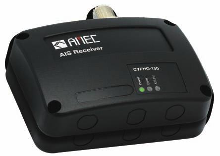
8 1 SYSTEM OVERVIEW 1.1 Product Description The AMEC CYPHO-150/150S is an AIS receiver series. It receives AIS navigation data from AIS-equipped vessels nearby and improves navigation safety. CYPHO-150 series is designed to inter-operate with AIS Class A or Class B transponders, and any other AIS station operating on the AIS VHF data link. CYPHO-150 series is built with two parallel AIS receivers in one box with optimized sensitivity. Having CYPHO-150 series AIS receiver on board, you can monitor the status of the vessels equipped with AIS transponders in the surrounding area by receiving their dynamic information (position, speed, SOG, etc.), static information (ship name, MMSI, call sign, etc.), and voyage related information (cargo type, destination, etc.). Equipped with USB2.0 and NMEA 0183, CYPHO-150 series enables connectivity to most available peripherals in the market. CYPHO-150S with integrated VHF splitter allows the usage of a single VHF antenna to combine AIS and VHF operation. 1.2 Comparison of CYPHO-150 Series Description CYPHO-150 CYPHO-150S Number of AIS Channels 2 2 USB port 1 1 NMEA input, 1 output (baud rate independent) 1 input, 1 output (baud rate independent) Built-in VHF Splitter - Yes 8

9 CYPHO-150 CYPHO-150S Front Front Back Back 9
10 1.3 Equipment in the Box Please contact your supplier immediately if there is any item missing. 10
11 1.4 External Connections 11
12 1.5 What is AIS? The Automatic Identification System (AIS) is a Very High Frequency (VHF) radio broadcasting system that transfers packets of data over the VHF data link (VDL) and enables AIS equipped vessels and shore-based stations to exchange identification information and navigational data. Ships with AIS transponders continually transmit their ID, position, course, speed and other data to all nearby ships and shore stations. Such information can aid greatly in situational awareness and provide a means to assist in collision avoidance. AIS equipment is standardized by ITU, IEC, IALA and IMO and is subject to approval by a certification body. The following AIS devices have been developed for variant applications. AIS Class A: mandated by the IMO for vessels of 300 gross tonnages and upwards engaged on international voyages, cargo ships of 500 gross tonnages and upwards, as well as passenger ships. It transmits typically on 12.5 watt output power. AIS Class B: provides limited functionality and is intended for non-solas commercial vessels and recreational vessels. It transmits typically on 2 watt output power. AIS Receiver: only receives AIS signal and it does not have transmitter to send out AIS signal. Suitable for recreational vessel that does not want to send out its vessel information. 12
13 AIS Base Station: is provided by aids-to-navigation authorities to enable the ship to shore / shore to ship transmission of information. Networked AIS Base Stations can assist in providing overall maritime domain awareness. AIS AtoN (Aids to Navigation): provides an opportunity to transmit position and status of buoys and lights through the same VDL, which can then show up on AIS-ready devices within the range. AIS SART: Search and Rescue Transmitter using AIS can be used to assist in determining the location of a vessel in distress. It is typically used on life rafts. AIS on Search and Rescue (SAR) Aircraft: used on airplanes and helicopters to assist search and rescue operation. 1.6 AIS Message Type The CYPHO-150 models can receive AIS messages from both Class A and Class B AIS transponders as well as from AIS Base Station, AIS AtoN, and AIS SART/MOB. The message types are listed as below table. The messages in gray color are transmitted only from class A AIS device. 13
14 Type of Message Static Data Voyage Related Data Dynamic Data Dynamic Reports SRM Data Details Maritime Mobile Service Identity (hereinafter called MMSI ) number IMO number Call sign and name Type of ship Length and beam GPS Antenna location Draught of the ship Cargo information Destination Estimate Time of Arrival (hereinafter called ETA ) Position of the vessel Coordinated Universal Time (hereinafter called Time in UTC.) Course Over Ground (hereinafter called COG ) Speed Over Ground (hereinafter called SOG ) Heading Rate of turn Navigational status Speed of the ship Status of the ship Alarm Safety 14
15 2 INSTALLATION Please note the following guidelines for selecting a suitable installation location for CYPHO-150. The surrounding temperature should be maintained between -15 C~55 C. The receiver must be installed at least 0.5m away from a compass. The device is not designed to be fully waterproof. Therefore, is not recommended to install the device in a location that will be subjected to spray or water submersion. The device should not be installed in flammable or hazardous locations such as near a fuel tank. The device should be installed in a location where the indicator is easily visible in which the LED lights provides important information about the status of the receiver. 15

16 2.1 CYPHO-150 Connection Interface VHF Antenna Power, USB, NMEA 0183 Figure 1 CYPHO-150 Connection Interface 16

17 2.2 CYPHO-150S Connection Interface VHF Radio VHF Antenna Power, USB, NMEA 0183 Figure 2 CYPHO-150S Connection Interface 17


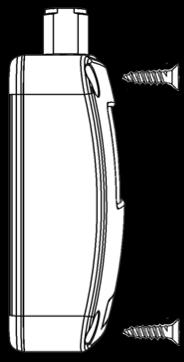

18 2.3 Mounting Instructions Platform Mounting Wall Mounting (flat surface) Figure 3 Mounting Instructions (1) 18
19 Figure 4 Mounting Instructions (2) 19
20 2.4 VHF Antenna Installation The quality and positioning of the antenna is the most important factor dictating AIS performance. It is recommended that a VHF antenna with omni-directional vertical polarization and specifically tuned for AIS operation band is used. Since the range of VHF signals is largely decided by line of sight distance, AIS antenna should be placed as high as possible and at least 5 meters away from any constructions made of conductive materials. To avoid interference, the VHF antenna location should be placed in accordance to Figure 5. DISTANCE BETWEEN ANTENNAS The safe distance from a transmitting VHF antenna is 60cm. DO NOT BEND CABLES Bending cables may cause damages to the inner wires and impair overall the performances. USES OF CABLE TUBE Each coaxial cable should be set up separately and can only be set up in a single cable tube. INSULATION ON CONNECTING PORT Connecting port of the coaxial cable should be insulated. 20
21 VHF Antenna Other transmitting antenna Other VHF Antenna The recommended vertical distance between antennas is 2m. The recommended horizontal distance between antennas is 10m. Figure 5 VHF Antenna Installation 21
22 2.5 Connecting to NMEA 0183 devices CYPHO-150 is typically connected to an external chartplotter via NMEA 0183 output wiring connection. (please refer to Figure 8) For the advanced multiplexing application, CYPHO-150 series gets input from one NMEA0138 device and pass it to another NMEA 0183 device together with AIS information. The input and output NMEA 0183 ports support independent baud rates. CYPHO-150 series supports three baud rates: 4800, 9600, and The default baud rate is Use the provided configuration utility to change the baud rates. See the illustration Figure 6. Figure 6 NMEA 0183 Connection 22
23 The figure below describes how to wire your AIS receiver with NMEA 0183 devices and power source. Figure 7 Wiring Instructions 23
24 CYPHO-150 NMEA 0183 RXP RXN TXP TXN Figure 8 External NMEA 0183 Device (RS422) (Chartplotter) TXP TXN RXP RXN NMEA 0183 Connection illustration Core Color at CYPHO-150 NMEA 0183 Signal Signal Direction (CYPHO-150) External NMEA 0183 Device Brown Receive + (RXP) Input n/a Blue Receive (RXN) Input n/a Yellow Transmit + (TXP) Output Data Input + (RXP) Green Transmit (TXN) Output Data Input (RXN) 24
25 CYPHO-150 NMEA 0183 RXP RXN TXP TXN Figure 9 External NMEA 0183 (GPS Source) TXP TXN External NMEA 0183 (Chartplotter) RXP RXN NMEA 0183 Multiplexing Connection Core Color at CYPHO-150 NMEA 0183 Signal Signal Direction (CYPHO-150) External NMEA 0183 Devices Brown Receive + (RXP) Input Data Output + (TXP) Blue Receive (RXN) Input Data Output - (TXN) Yellow Transmit + (TXP) Output Data Input + (RXP) Green Transmit (TXN) Output Data Input (RXN) 25
26 2.6 Connecting to Power Supply All CYPHO-150 models are designed having no physical On/Off switch. Thus, the vessel s operation determines the unit s power status. The AIS Receiver requires a 12V or 24V DC power supply ( V). The red wire and the black wire on the 12 pin cable are used to connect the power supply s positive and negative terminals. Practically, it is suggested to use the 2 amp fuse panel before connecting directly to the battery/power supply. CYPHO-150 can also be powered via a standard PC USB port (5 volts at 500 ma) or an USB power adapter (5 volts at 500 ma). Note: If PC could not recognize USB connection after a power restart on CYPHO-150, please re-plug the USB connector. 26

27 3 CONFIGURATION 3.1 USB Driver Installation Your PC needs to install the USB driver in able to connect the AIS receiver. Locate the USB driver in the CD-ROM. Follow the instructions below to finish the installation. Step 1: Open the USB Driver file and double click on USBDriverInstaller.exe to install the driver. Please click on Install Drivers to continue. Figure 10 USB Driver Installation (1) 27


28 Step 2: A security reminder appears and asks for your confirmation. Click Install to proceed. Figure 11 USB Driver Installation (2) Step 3: Driver installation is completed. Close the window directly using the close window icon. Figure 12 USB Driver Installation (3) 28
29 3.2 CYPHO Configuration Software Install the AMEC Cypho Configuration Software from the CD-ROM by following the on-screen instructions Connecting the Receiver to your PC There are 2 options to connect the software with your AIS receiver: Auto: The system will scan all connected ports and their available baud rates and establish connection automatically. Manual: Configure baud rate and serial port manually. The default baud rate is

30 Serial port number Default Baud Rate NMEA 0183 Baud Rate Figure 13 Software Installation (1) To find the serial port number, click Start Control Panel Device Manager. Expand the Ports section and look for USB Communications Port. In the sample picture below, the serial port number is

31 Serial port number Figure 14 Software Installation (2) Enter the value and hit Connect to link the computer to the receiver. 31
32 3.2.2 Baud Rate Setting: Each CYPHO-150 model has one NMEA 0138 port and the baud rate of its input and output ports can be set independently. To adjust the values, set the desired baud rates for the NMEA input and output and then click on Config Device to apply new the setting. Figure 15 Baud Rates 32

33 3.2.3 Diagnosis The Diagnosis tab has two submenus, System Check and Data Log. System Check System Check retrieves following information and statuses from the receiver: Firmware Version, Product Serial Number, RX position reports. Figure 16 System Check 33

34 Data Log The Data Log enables user to record received AIS information. To enable or disable the recording of AIS information, use the Enable Log check box. Click Save to save the record at a preferred location on the PC via USB. To ensure the log is recorded the device must stay connected to the PC via USB and the AMEC CYPHO Configuration Software is running. To clear the current listing, use the Clear button. Figure 17 Data Log 34


35 3.3 AMEC AIS Viewer Software Installation AIS Viewer is a complementary application that provides a simple access for user to view AIS information on PC. The application provides basic features to browse the relative positions of surrounding vessels and the dynamic and static information regulated by IMO. For professional uses, we recommend connecting AMEC CYPHO-150 Series with other marine electronic products such as ECS or Radar for better performances. The AMEC AIS Viewer program and its operation manual are included in the CD-ROM. Figure 18 AMEC AIS Viewer 35
36 4 GETTING STARTED 4.1 CYPHO-150 LED Indicators Power Error AIS Rx Figure 19 CYPHO-150 LED Indicators LED INDICATIONS Indicator Indication Description Power Normal Steady Green Device in normal operation Error Flashing Red A system error is detected AIS Rx Flashing Green Receiving of AIS message in either AIS Channel 1 or Channel 2 36


37 4.2 CYPHO-150S LED Indicators Power Error AIS Rx Radio Tx Figure 20 CYPHO-150S LED Indicators LED INDICATIONS Indicator Indication Description Power Normal Steady Green Device in normal operation Error Flashing Red A system error is detected AIS Rx Flashing Green Receiving of AIS message in either AIS Channel 1 or Channel 2 Radio Tx Flashing Green VHF radio is transmitting 37
38 5 SPECIFICICACIONS 5.1 Product Specifications APPLICABLE STANDARDS IEC (applicable parts) ITU-R M.1371 (applicable parts) IEC (applicable parts) IEC (applicable parts) AIS RECEIVER Number of AIS Receivers 2 channels CH-1 Default CH 87B ( MHz) CH-2 Default CH 88B ( MHz) Channel Bandwidth 25KHz Message Format AIS Class A & B messages Data Rate 9,600bps / per channel AIS Receiver Sensitivity -112dBm Max. Usable Sensitivity PER -107 dbm POWER SUPPLY Supply Voltage 12 / 24V DC USB Power 5V DC / 500 ma Power Consumption <1.50 Watt LED INDICATION CYPHO-150 Power, Error, AIS Rx CYPHO-150S Power, Error, AIS Rx, Radio Tx 38
39 INTERFACE VHF Antenna Connector SO-239 (Female) NMEA (default), 9600, 4800 bps USB 2.0 Supported VHF Radio Connector (CYPHO-150S only) SO-239 (Female) ENVIRONMENTAL Operating Temperature -15 C~55 C Storage Temperature -25 C~70 C Humidity Operation 0~95% RH at 40 C Vibration IEC Waterproof IPX2 PHYSICAL Size in mm (w) 128 mm (4.99 inch) Size in mm (h) 36 mm (1.40 inch) Size in mm (d) 88 mm (3.43 inch) Weight 210g (incl. cable) Cable Length (power, USB, NMEA 0183) 1M RF PERFORMANCE (CYPHO-150S only) Frequency Range ~ MHz AIS Receiver Sensitivity -110dBm (when not connecting to DSC) VHF Port Insertion Loss Receiver Path: 3.5dB Transmit Path: 1.2dB Certification CE, FCC 39
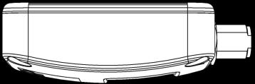
40 5.2 Dimensions Applicable to all CYPHO-150 models. Front View Figure 21 Front View 40
41 Side View 36 mm 88 mm 1m Figure 22 Side View 41
42 6 TROUBLESHOOTING 1 Does CYPHO-150 work with my chartplotter? New chartplotters typically support AIS function. Be sure your chartplotter has the latest firmware update. Ensure the baud rate for the inbound NMEA port on the chartplotter is matched How do I know the CYPHO-150 functions normally? The Power LED indicates in steady Green. The AIS Rx LED indicates in flashing Green. Can CYPHO-150 pass the received AIS information to PC? Yes, the unit can pass the AIS message sentences through USB port to PC. Why the unit does not power up? Check the unit has adequate power. Be sure that the polarities of the power wires are correct (red is positive, black is negative ground) 5 Can CYPHO-150 NMEA interface be connected to more than two external NMEA devices? Yes, through a NMEA multiplexing connection. 6 Can a VHF antenna other than AMEC VHF antenna be used for CYPHO-150? Yes, as long as it is a marine type VHF antenna. 42
43 7 ABBREVIATIONS AIS COG CPA CSTDMA DSC ECS ETA GPS IMO MMSI SOG SRM TCPA TDMA UTC VHF VTS Automatic Identification System Course Over Ground Distance to Closest Point of Approach Carrier-sense time division multiple access Digital Selective Calling Electronic Chart System Estimated Time of Arrival Global Positioning System International Maritime Organization Maritime Mobile Service Identity Speed Over Ground Safety Related Message Time to Closest Point of Approach Time Division Multiple Access Coordinated Universal Time Very High Frequency Vessel Traffic Service 43
44 8 FCC INTERFERENCE STATEMENT This equipment has been tested and found to comply with the limits for a Class A digital device, pursuant to Part 15 of FCC Rules. These limits are designed to provide reasonable protection against harmful interference in a residential installation. This equipment generates uses and can radiate radio frequency energy and, if not installed and used in accordance with the instructions, may cause harmful interference to radio communications. However, there is no guarantee that interference will not occur in a particular installation. If this equipment does cause harmful interference to radio or television reception, which can be determined by turning the equipment off and on, the user is encouraged to try to correct the interference by one of the following measures: Reorient or relocate the receiving antenna. Increase the separation between the equipment and receiver. Connect the equipment into an outlet on a circuit different from that to which the receiver is connected. Consult the dealer or an experienced radio/tv technician for help. This device complies with Part 15 of the FCC Rules. Operation is subject to the following two conditions: 1) This device may not cause harmful interference, and 2) this device must accept any interference received, including interference that may cause undesired operation. 44
45 DECLARATION OF CONFORMITY Hereby, Alltek Marine Electronics Corp. (AMEC) declares that this CYPHO-150/150S is in compliance with the essential requirements and other relevant provisions of Directive 1999/5/EC. AMEC WORLDWIDE WARRANTY Limited warranty Subject to the terms, conditions and limitations set forth in this Worldwide Limited Warranty (hereinafter the Warranty ), AMEC warrants that its products, when properly installed and used, will be free from defects in material and workmanship for a period of twelve (12) months, from the date of first purchase (the Warranty Period ) For the purposes of this warranty, date of first purchase means the date that the product was purchased by the first retail customer, or by the institutional customer, or in the case of a product installed on a new vessel or any other marine related platform by a certified AMEC original equipment manufacturer (a AMEC OEM ), the date that such vessel was purchased by the first retail customer. AMEC will, at its sole option, repair or replace any defective products or components returned during the Warranty Period in accordance with the terms, conditions and limitations set forth below. Such repairs or replacement will be the sole remedy of the customer under this Warranty. 45
46 Standard Warranty Service To qualify for standard warranty service the product must be returned to a AMEC-certified service agent (i) within the Warranty Period, and (ii) within thirty (30) days of the alleged product failure. Any products returned must be securely packaged and sent pre-paid and insured to AMEC or to a AMEC-certified service agent. All products returned must be accompanied by a copy of the original sales receipt to be eligible for standard warranty service. Other conditions This Warranty is fully transferable provided that you furnish the original proof of purchase to the AMEC -certified service agent. This Warranty is void if the seal label is removed or defaced. THE LIABILITY OF AMEC TO A CUSTOMER UNDER THIS WARRANTY, WHETHER FOR BREACH OF CONTRACT, TORT, BREACH OF STATUTORY DUTY OR OTHERWISE SHALL IN NO EVENT EXCEED AN AMOUNT EQUAL TO THE TOTAL PURCHAE PRICE OF THE PRODUCT GIVING RISE TO SUCH LIABILITY AND IN NO EVENT SHALL AMEC BE LIABLE FOR SPECIAL, INCIDENTAL, CONSEQUENTIAL OR INDIRECT DAMAGES OR LOST OF GOODWILL, REPUTATION, LOSS OF OPPORTUNITY OR INFORMATION, DATA, SOFTWARE OR APPLICATIONS. In the event that any term or provision contained in this Warranty is found to be invalid, illegal or unenforceable by a court of competent jurisdiction, then such provision shall be deemed modified to the extent necessary to make such provision enforceable by such court, taking into account the intent of the parties. All AMEC products sold or provided hereunder are merely aids to navigation. It is the responsibility of the user to exercise discretion and proper navigational skill independent of any AMEC product. 46
47 Alltek Marine Electronics Corporation 5F, No. 37, Ji-Hu Road, Neihu District, Taipei, 11492, Taiwan Tel: Fax: service@alltekmarine.com Website:
General Information Manual Edition 1.08
 General Information Manual Edition 1.08 i. Copyright The entire contents of this instruction manual, including any future updates, revisions, and modifications, shall remain the property of AMEC at all
User s Manual COPYRIGHT DISCLAIMER
 COPYRIGHT The entire contents of this instruction manual, including any future updates, revisions, and modifications, shall remain the property of AMEC at all times. Unauthorized copies or reproduction
General Information Manual Edition 1.04
 General Information Manual Edition 1.04 i. Copyright The entire contents of this instruction manual, including any future updates, revisions, and modifications, shall remain the property of AMEC at all
Manual Revision: Version 1.06
 COPYRIGHT The entire contents of this instruction manual, including any future updates, revisions, and modifications, shall remain the property of AMEC at all times. Unauthorized copies or reproduction
Manual Revision: Version 1.11
 COPYRIGHT The entire contents of this instruction manual, including any future updates, revisions, and modifications, shall remain the property of AMEC at all times. Unauthorized copies or reproduction
Smartfind M15, M15S & M15SW AIS Receiver User Manual
 Smartfind M15, M15S & M15SW AIS Receiver User Manual General Information i. Copyright The entire contents of this instruction manual, including any future updates, revisions, and modifications, shall remain
CAMINO-108S. AIS Class B with Integrated Splitter USER MANUAL
 CAMINO-108S AIS Class B with Integrated Splitter USER MANUAL COPYRIGHT The entire contents of this instruction manual, including any future updates, revisions, and modifications, shall remain the property
COPYRIGHT DISCLAIMER. Contact us at:
 COPYRIGHT The entire contents of this instruction manual, including any future updates, revisions, and modifications, shall remain the property of AMEC at all times. Unauthorized copies or reproduction
AIS 300 Installation Instructions
 Use these instructions to install the Garmin AIS 300 Automatic Identification System (AIS) Class B receiver device. Compare the contents of this package with the packing list on the box. If any pieces
NSPL-500. AIS/VHF antenna splitter. User Manual ENGLISH.
 NSPL-500 AIS/VHF antenna splitter User Manual ENGLISH www.bandg.com www.simrad-yachting.com www.lowrance.com Preface As Navico is continuously improving this product, we retain the right to make changes
Thank you for buying this AIS receiver.
 Thank you for buying this AIS receiver. This product has been engineered to offer you the highest level of performance and durability and we hope that it will provide many years of reliable service. We
Thank you for buying this AIS antenna splitter.
 Thank you for buying this AIS antenna splitter. This product has been engineered to offer you the highest level of performance and durability and we hope that it will provide many years of reliable service.
Sales & Marketing: Version 1.01
 User s Manual II COPYRIGHT The entire contents of this instruction manual, including any future updates, revisions, and modifications, shall remain the properties of AMEC at all times. Unauthorized copies
Watcheye S AIS Splitter. manual
 Watcheye S AIS Splitter manual Thank you for buying this AIS antenna splitter. This product has been engineered to offer you the highest level of performance and durability and we hope that it will provide
CAMINO-108S. AIS Class B with Integrated Splitter USER MANUAL
 CAMINO-108S AIS Class B with Integrated Splitter USER MANUAL COPYRIGHT The entire contents of this instruction manual, including any future updates, revisions, and modifications, shall remain the property
KS-200A/B. ˵à Êé. AIS Class B Transponder KS-200A AIS Receiver KS-200B
 R KS-200A/B KS-200A/B ˵à Êé OPERATOR`S MANUAL AIS Class B Transponder KS-200A AIS Receiver KS-200B SAFETY INSTRUCTIONS Safety Instructions for the Operator WARNING Do not open the equipment. Only qualified
COPYRIGHT DISCLAIMER. Contact us at:
 COPYRIGHT The entire contents of this instruction manual, including any future updates, revisions, and modifications, shall remain the property of AMEC at all times. Unauthorized copies or reproduction
HIGH PERFORMANCE MARITIME. em-trak S100 PRODUCTS. Antenna splitter. Product Manual. High Performance Maritime Products
 em-trak S100 MARITIME PRODUCTS HIGH PERFORMANCE Antenna splitter Product Manual High Performance Maritime Products www.em-trak.com 201-0206:3 Contents 1 - Notices...1 1.1 - Safety warnings...1 1.2 - General
Manual Revision: Version 1.30
 COPYRIGHT The entire contents of this instruction manual, including any future updates, revisions, and modifications, shall remain the property of AMEC at all times. Unauthorized copies or reproduction
ANTENNA SpliTTEr. Zero loss active VHF antenna splitter. I N s t r u c t i o n m a n u a l
 ANTENNA SpliTTEr Zero loss active VHF antenna splitter I N s t r u c t i o n m a n u a l w w w. g m e. n e t. a u Thank you for buying this AIS antenna splitter. This product has been engineered to offer
Installation and Quick Reference Guide. Disclaimer and warranty 2. Contents of this box 2. Brief background to AIS 3.
 AI3000 AIS Receiver ai3000vf rev 6b Installation and Quick Reference Guide Contents Page Number Disclaimer and warranty 2 Contents of this box 2 Brief background to AIS 3 Introduction 3 Installing the
HIGH PERFORMANCE MARITIME. em-trak R100 PRODUCTS. AIS Dual Channel Receiver. Product Manual. High Performance Maritime Products
 em-trak R100 MARITIME PRODUCTS HIGH PERFORMANCE AIS Dual Channel Receiver Product Manual High Performance Maritime Products www.em-trak.com 201-0138:2 Contents 1 - Notices...1 1.1 - Safety warnings...1
RFTX-1 Installation Manual
 RFTX-1 Installation Manual complete control Universal Remote Control RFTX-1 Installation Manual 2009-2014 Universal Remote Control, Inc. The information in this Owner s Manual is copyright protected. No
Technical Support, End User License & Warranty Information
 Technical Support, End User License & Warranty Information How to get Technical Support Pazzles provides free Technical Support for your Inspiration Vūe for a period of 1 year from the date of purchase.
LD2342 USWM V1.6. LD2342 V1.4 Page 1 of 18
 LD2342 USWM V1.6 LD2342 V1.4 Page 1 of 18 GENERAL WARNINGS All Class A and Class B marine Automatic Identification System (AIS) units utilize a satellite based system such as the Global Positioning Satellite
AIS Training. AIS Technology in Digital Yacht Products Explained. Digital Yacht Ltd TEL
 AIS Training AIS Technology in Digital Yacht Products Explained Digital Yacht Ltd www.digitalyacht.co.uk TEL + 44 1179 554474 What is AIS? The Automatic Identification System (AIS) is the biggest advance
ACT-IR220L/LE IrDA Serial Port Adapter
 ACT-IR220L/LE IrDA Serial Port Adapter Product Specification Summary ACTiSYS Corp. 48511 Warm Springs Blvd, Suite 206 Fremont, CA 94539, USA TEL: (510) 490-8024, FAX: (510) 623-7268 E-Mail: irda-support@actisys.com
ACT-IR220Li/220LN IrDA Serial Port Adapter
 ACT-IR220Li/220LN IrDA Serial Port Adapter Product Specification Summary ACTiSYS Corp. 48511 Warm Springs Blvd, Suite 206 Fremont, CA 94539, USA TEL: (510) 490-8024, FAX: (510) 623-7268 E-Mail: irda-support@actisys.com
CCR24T CCR24R. User s Guide WIRELESS TRANSMITTER SYSTEM WARRANTY SERVICE CARD WARRANTY CARD
 WARRANTY SERVICE CARD WARRANTY CARD PRODUCT NAME Wireless Transceiver System PERIOD MODEL NAME CCR24GEN YEAR PURCHASE DATE.. 200_ From the date of WARRANTY PERIOD.. 200_ purchase. CUSTOMER S ADDRESS :
User's Guide. Wireless AC Circuit Identifier. Models RT30 and RT32
 User's Guide Wireless AC Circuit Identifier Models RT30 and RT32 Introduction Congratulations on your purchase of Extech s Model RT30 (914Mhz) or RT32 (869MHz) Wireless AC Circuit Identifier. The detector
Field Hub Installation Guide. P/N Rev. C 05/15
 Field Hub Installation Guide P/N016-0171-380 Rev. C 05/15 E21714 Copyright 2015 Disclaimer While every effort has been made to ensure the accuracy of this document, Raven Industries assumes no responsibility
User s Guide FM Transmitter
 TM 12-634 User s Guide FM Transmitter Please read this user s guide before using your new FM Transmitter. 12-634_en.indd 1 Package contents FM Transmitter USB Cable User s Guide Quick Start IMPORTANT SAFETY
Class B AIS Transceiver Mariner X2 Automatic Identification System
 Class B AIS Transceiver Mariner X2 Automatic Identification System INSTALLATION MANUAL Version 1.4 Thank you for buying this AIS Class B transceiver. This product has been engineered to offer you the highest
14 CHANNEL FAMILY RADIO SYSTEM MODEL # FR142
 14 CHANNEL FAMILY RADIO SYSTEM MODEL # FR142 2001 Audiovox Electronics Corp., Hauppauge, NY 11788 Printed in China 128-6020 052FR142104 BEFORE OPERATING THIS PRODUCT PLEASE READ THESE INSTRUCTIONS COMPLETELY
User Manual Digital Wireless Rain Gauge
 Rain Gauge Specifications: User Manual Digital Wireless Rain Gauge - Outdoor rain gauge transmitter measures the rainfall and transmits the data to an indoor rain monitor base unit which shows the rainfall
ORiNOCO AP-4000MR-LR and AP-4900MR-LR Access Points Safety and Regulatory Compliance Information
 IMPORTANT! Visit http://support.proxim.com for the latest safety and regulatory compliance information for this product. ORiNOCO AP-4000MR-LR and AP-4900MR-LR Access Points Safety and Regulatory Compliance
INSTRUCTION MANUAL. IBRit - rf1 - usb PC - Station for wireless Data transmission. M e s s t e c h n i k. Messtechnik GmbH & Co.
 M e s s t e c h n i k INSTRUCTION MANUAL PC - Station for wireless Data transmission Document No. : D1F604 001 Version : April 2006 Copyright : IBR Messtechnik GmbH & Co. KG Contents 1. Introduction 1.1
HIGH PERFORMANCE MARITIME PRODUCTS. em-trak B212 AIS Class B Transceiver. Product Manual. High Performance Maritime Products.
 em-trak B212 AIS Class B Transceiver MARITIME PRODUCTS HIGH PERFORMANCE Product Manual High Performance Maritime Products www.em-trak.com Thank you for buying this AIS Class B transceiver. This product
Thank you for buying this AIS Class B transceiver.
 Thank you for buying this AIS Class B transceiver. This product has been engineered to offer you the highest level of performance and durability and we hope that it will provide many years of reliable
900MHz Digital Hybrid Wireless Outdoor Speakers
 4015004 900MHz Digital Hybrid Wireless Outdoor Speakers User s Manual This 900 MHz digital hybrid wireless speaker system uses the latest wireless technology that enables you to enjoy music and TV sound
PTT- Z or PTT-U PUSH-TO-TALK Specification
 Federal Communication Commission Interference Statement This equipment has been tested and found to comply with the limits for a Class B digital device, pursuant to Part 15 of the FCC Rules. These limits
 Register your product and get support at www.philips.com/welcome English EN User manual Contents English 1 Important 4 Safety 4 Notice for USA 4 Notice for Canada 4 Recycling 4 2 Your SDV6122 5 Overview
Wireless Z-Wave Control ZRP-100US Z-Wave Repeater USER MANUAL. Introduction
 Wireless Z-Wave Control ZRP-100US Z-Wave Repeater USER MANUAL Introduction Thank you for choosing ZRP-100 Z-Wave Repeater product! ZRP-100 is a Z-Wave repeater with best RF performance to repeat Z-Wave
SRT Marine Technology. LD2342 V1.4 Page 1 of 22
 LD2342 V1.4 Page 1 of 22 LD2342 V1.4 Page 2 of 22 2 LD2342 V1.4 Page 3 of 22 GENERAL WARNINGS All marine Automatic Identification System (AIS) units utilise a satellite based system such as the Global
Manual Unihan UPWL6024
 Manual Unihan UPWL6024 Federal Communications Commission Statement This device complies with FCC Rules Part 15. Operation is subject to the following i. This device may not cause harmful interference,
Doug Miller Milltech Marine Inc. Milltech Marine 1
 Doug Miller Milltech Marine Inc. www.milltechmarine.com Milltech Marine 1 What I ll Cover What is AIS? AIS Transponders AIS Receivers Typical Usage Scenarios What s new and what s coming Questions Milltech
USER MANUAL MODEL Parallel to Serial/ Serial to Parallel Interface Converter
 USER MANUAL MODEL 2029 Parallel to Serial/ Serial to Parallel Interface Converter C E R T I F I E D An ISO-9001 Certified Company Part #07M2029-B, Rev. C Doc. #102011UB Revised 6/16/09 SALES OFFICE (301)
SP GHz Digital Wireless Speakers. User s Manual. Please read before using the equipment. Please visit for details.
 SP1390 2.4GHz Digital Wireless Speakers User s Manual Please read before using the equipment. Please visit www.promowide.com for details. INTRODUCTION This 2.4G digital wireless speakers system uses latest
The FA-50 offers accurate information for collision avoidance
 The FA-50 offers accurate information for collision avoidance with GPS antenna GPA-017S FURUNO s FA-50 class-b AIS transponder receives navigation data from AIS-equipped vessels nearby that can be utilized
Pocket Weatheradio with Tone and Vibrating Alert
 Pocket Weatheradio with Tone and Vibrating Alert OWNER S MANUAL Please read before using this equipment. Your RadioShack Pocket Weatheradio is designed to receive National Weather Service (NWS) broadcasts,
INSTRUCTION MANUAL MODEL SAS RS-7 LASER DISTANCE METER
 INSTRUCTION MANUAL MODEL SAS RS-7 LASER DISTANCE METER KEYS, DISPLAYS AND FUNCTIONS GENERAL SAFETY RULES! DANGER! Do not aim light at persons or animals. Do not stare into the laser light source. Laser
Owner s Manual. MRX-2 Network Base Station
 Owner s Manual MRX-2 Network Base Station MRX-2 Owner s Manual 2014 Universal Remote Control, Inc. The information in this manual is copyright protected. No part of this manual may be copied or reproduced
Disclaimers. Important Notice
 Disclaimers Disclaimers Important Notice Copyright SolarEdge Inc. All rights reserved. No part of this document may be reproduced, stored in a retrieval system, or transmitted, in any form or by any means,
TARGETuner Antenna Management System for Screwdriver Antennas
 TARGETuner Antenna Management System for Screwdriver Antennas www.westmountainradio.com 1020 Spring City Drive Waukesha, WI 53186 262-522-6503 sales@westmountainradio.com 2014, All rights reserved. All
802.11n, 2.4G 1T1R Wireless LAN PCI Express Half Mini Card
 802.11n, 2.4G 1T1R Wireless LAN PCI Express Half Mini Card WN6605LH Realtek RTL8191SE User s Manual Ben J. Chen 3/4/2010 Federal Communication Commission Interference Statement This equipment has been
Ditch Witch 750 Tracker Specs Provided by FOREWORD
 750/752 Display - FOREWORD 1 Ditch Witch 750 Tracker Specs Provided by www.aaatesters.com FOREWORD This manual is an important part of your equipment. It provides safety information and operation instructions
900 MHz Digital Wireless Indoor/Outdoor Speakers
 4015007 900 MHz Digital Wireless Indoor/Outdoor Speakers User s Manual This 900 MHz digital hybrid wireless speaker system uses the latest wireless technology that enables you to enjoy music and TV sound
DIGICELL ANYNET NETWORK ACCESS MODULE
 Comm Activity Network Status Service DigiCell Any NET Network Access Module Network Interface Network Service AMPS Cellemetry GSM SMS CDMA GPRS Ethernet 1xRTT RS-232 TCP/IP Input 1 Standard S3 off, S4
User Manual. ProRF Encoder Transmitter & Receiver
 User Manual ProRF Encoder Transmitter & Receiver WARRANTY Accurate Technology, Inc. warrants the ProScale Systems against defective parts and workmanship for 1 year commencing from the date of original
Manual and User Guide
 Manual and User Guide TV Talker FM System Model WFM 260 Model WFM 270 Transmitter Model WFM TX260 Receiver Model WFM RX260 Receiver Model WFM RX270 MAN 151H 2011 Williams Sound, LLC Contents Page System
Manual Unihan UPWL6025
 Manual Unihan UPWL6025 Federal Communications Commission Statement This device complies with FCC Rules Part 15. Operation is subject to the following i. This device may not cause harmful interference,
Owner s Manual. MRX-2 Network Base Station
 Owner s Manual MRX-2 Network Base Station MRX-2 Owner s Manual 2014 Universal Remote Control, Inc. The information in this manual is copyright protected. No part of this manual may be copied or reproduced
FURUNO DEEPSEA WORLD Class-A Universal AIS Automatic Identification System. The future today with FURUNO's electronics technology.
 R FURUNO DEEPSEA WORLD Class-A Universal AIS Automatic Identification System Model FA-100 The AIS improves the safety of navigation by assisting in the efficient navigation of ships, protection of the
AIT2000 CLASS B AIS TRANSPONDER
 IMPORTANT NOTE The USB cable of the AIT2000 is designed to be used for configuring/programming the unit during installation and not for permanent connection to the boat s Navigation PC. If you intend to
Gypsy Statement of Limited Warranty. Part 1 General Terms
 Gypsy Statement of Limited Warranty Part 1 General Terms This Statement of Limited Warranty includes Part 1 General Terms, and Part2 Warranty Information. The warranties provided by PROVO CRAFT AND NOVELTY,
INSTALLATION AND OPERATING MANUAL
 INSTALLATION AND OPERATING MANUAL FOR RBDA-PCS-1/25W-90-A INDOOR REPEATER TABLE OF CONTENTS PARAGRAPH PAGE NO BDA OVERVIEW 3 BDA BLOCK DIAGRAM DESCRIPTION 3 FCC INFORMATION FOR USER 3 BDA BLOCK DIAGRAM
USER MANUAL Digital Wireless Gateway U9120-W4 (P/N: 44002G-01)
") USER MANUAL Digital Wireless Gateway U9120-W4 (P/N: 44002G-01) 19549P-82 (11-16) 2016 DAVID CLARK COMPANY INCORPORATED Cautions and Warnings READ AND SAVE THESE INSTRUCTIONS. Follow the instructions in
USER MANUAL Digital Wireless Gateway U9120-W4 (P/N: 44002G-01) 19549P-82 (11-16) 2016 DAVID CLARK COMPANY INCORPORATED Cautions and Warnings READ AND SAVE THESE INSTRUCTIONS. Follow the instructions in
easypos N HOOK - Transmitter Manual
 easypos N HOOK - Transmitter Manual easypos N HOOK Maritime Locating System Product No.: A140 Rev. 1.4 Weatherdock AG. Sigmundstraße 180 D-90431 Nürnberg Tel. :+49 911 37 66 38 30 Fax: +49 911 37 66 38
Owner s Manual MRX-10 Advanced Network System Controller
 Owner s Manual MRX-10 Advanced Network System Controller MRX-10 Owner s Manual 2015 Universal Remote Control, Inc. The information in this Owner s Manual is copyright protected. No part of this manual
ER200 COMPACT EMERGENCY CRANK DIGITAL WEATHER ALERT RADIO OWNER S MANUAL
 ER200 COMPACT EMERGENCY CRANK DIGITAL WEATHER ALERT RADIO OWNER S MANUAL Table of Contents -------------------------------------- 2 Features ----------------------------------------------- 3 Controls and
RM24100D. Introduction. Features. 2.4GHz 100mW RS232 / RS485 / RS422 DSSS Radio Modem (IEEE compliant) Operating Manual English 1.
 Operating Manual English 1.") RM24100D 2.4GHz 100mW RS232 / RS485 / RS422 DSSS Radio Modem (IEEE 802.15.4 compliant) Operating Manual English 1.09 Introduction The RM24100D radio modem acts as a wireless serial cable replacement and
RM24100D 2.4GHz 100mW RS232 / RS485 / RS422 DSSS Radio Modem (IEEE 802.15.4 compliant) Operating Manual English 1.09 Introduction The RM24100D radio modem acts as a wireless serial cable replacement and
GX_W60_V3.5 WIFI Video module Mnaual
 GX_W60_V3.5 WIFI Video module Mnaual W60 Tel:86-755-26066032 Fax:26002892 Web site:www.netopsun.com 1 / 8 1 summary 1.1 overview of the whole W60_WIFI module is the latest introduction of crown Asahi Technology
Radio Controlled timekeeping. Receives 60KHz WWVB signal transmitted by NIST in Fort Collins, Colorado
 Congratulation on your purchase of an Atomix Radio Controlled clock. Radio Controlled technology allows for the most accurate time keeping available as well as automatic changes for Daylight Saving Time
RM24100A. *Maximum transmit power output levels and local radio frequency regulator bodies must be obeyed in the country of operation.
 RM24100A 2.4GHz 100mW RS232 / RS485 / RS422 DSSS Radio Modem (IEEE 802.15.4 compliant) Operating Manual English 1.02 Introduction The RM24100A radio modem acts as a wireless serial cable replacement and
NEO CAR AUDIO. Neo AUXiN AUX INPUT INTERFACE. Instruction Manual
 NEO CAR AUDIO Neo AUXiN AUX INPUT INTERFACE Instruction Manual IMPORTANT NOTE Neo AUXiN Dip switch positions MUST be set BEFORE any other step is taken. Otherwise, the kit will not operate properly. See
Quick Start Guide. Version: 1.0 F/W: V1.2.0_RC1b. Date: December 11, 2017
 VigorAP 920R Series Ruggedized Outdoor AP with Extreme 802.11ac Power Warranty Quick Start Guide Version: 1.0 F/W: V1.2.0_RC1b Date: December 11, 2017 We warrant to the original end user (purchaser) that
Quick Start Guide. Antenna Alignment Tool AIMWLLR0-35. QSG rev 7 AIMWLLR0-35 [NRB-0200] QSG.indd 1
![Quick Start Guide. Antenna Alignment Tool AIMWLLR0-35. QSG rev 7 AIMWLLR0-35 [NRB-0200] QSG.indd 1](/thumbs/86/94268876.jpg "Quick Start Guide. Antenna Alignment Tool AIMWLLR0-35. QSG rev 7 AIMWLLR0-35 [NRB-0200] QSG.indd 1") Quick Start Guide Antenna Alignment Tool AIMWLLR0-35 QSG-00097 rev 7 AIMWLLR0-35 [NRB-0200] QSG.indd 1 Welcome This quick start guide is designed to familiarize you with the features and use of the NetComm
Quick Start Guide Antenna Alignment Tool AIMWLLR0-35 QSG-00097 rev 7 AIMWLLR0-35 [NRB-0200] QSG.indd 1 Welcome This quick start guide is designed to familiarize you with the features and use of the NetComm
Manual Unihan UPWL6580
 Manual Unihan UPWL6580 Federal Communications Commission Statement This device complies with FCC Rules Part 15. Operation is subject to the following i. This device may not cause harmful interference,
Model 5100F. Advanced Test Equipment Rentals ATEC (2832) OWNER S MANUAL RF POWER AMPLIFIER
 OWNER S MANUAL RF POWER AMPLIFIER") Established 1981 Advanced Test Equipment Rentals www.atecorp.com 800-404-ATEC (2832) OWNER S MANUAL Model 5100F RF POWER AMPLIFIER 0.8 2.5 GHz, 25 Watts Ophir RF 5300 Beethoven Street Los Angeles, CA 90066
Established 1981 Advanced Test Equipment Rentals www.atecorp.com 800-404-ATEC (2832) OWNER S MANUAL Model 5100F RF POWER AMPLIFIER 0.8 2.5 GHz, 25 Watts Ophir RF 5300 Beethoven Street Los Angeles, CA 90066
Using the USB Output Port to Charge a Device
 Table of Contents ----------------------------------- 2 Features ----------------------------------------------- 3 Controls and Functions ---------------------------------- 4 ER210 Power Sources -----------------------------------
HIGH PERFORMANCE MARITIME. em-trak B100 PRODUCTS. AIS Class B Transceiver. Product Manual. High Performance Maritime Products
 em-trak B100 MARITIME PRODUCTS HIGH PERFORMANCE AIS Class B Transceiver Product Manual High Performance Maritime Products www.em-trak.com Contents 1 - Notices...1 1.1 - Safety warnings...1 1.2 - General
CRUX II/BTGPS USER GUIDE. Model:D1598
 CRUX II/BTGPS USER GUIDE Model:D1598 0 Federal Communication Commission Interference Statement This equipment has been tested and found to comply with the limits for a Class B digital device, pursuant
Installation & Quick Start Guide AIT2000 Class B AIS Transponder
 Installation & Quick Start Guide AIT2000 Class B AIS Transponder QUICK START AIT2000 - VR1.01 1. Introduction Congratulations on the purchase of your AIT2000 Class B AIS Transponder. It is recommended
Schooners II. Weatherproof Wireless 900MHz Speaker System. User Guide. Model no.: GDI-AQSHR200 / AQSHR21
 Schooners II Weatherproof Wireless 900MHz Speaker System User Guide Model no.: GDI-AQSHR200 / AQSHR21 IMPORTANT: Please read your User s Guide before using your system INTRODUCTION Your SCHOONERS II speaker
MedRx Avant Polar HIT AH-I-MPHITS-5 Effective 11/07/11
 INSTALLATION MANUAL 2 Contents Getting To Know Your AVANT POLAR HIT TM... 4 Setting up the System... 6 Software Installation... 7 Driver Installation Windows 7... 10 Driver Installation Windows XP... 13
HIGH PERFORMANCE MARITIME. em-trak B100 PRODUCTS. Product Manual.
 em-trak B100 MARITIME PRODUCTS HIGH PERFORMANCE Product Manual www.em-trak.com Contents 1 - Notices...1 1.1 - Safety warnings...1 1.2 - General notices...1 2 - About your AIS class B transceiver...6 2.1
Ambient Weather F007TP 8-Channel Wireless Probe Thermometer User Manual
 Ambient Weather F007TP 8-Channel Wireless Probe Thermometer User Manual Table of Contents 1 Introduction... 2 2 Getting Started... 2 2.1 Parts List... 2 2.2 Probe Thermometer Sensor Set Up... 2 3 Remote
MWC2-9. Operation Manual. MWC MHz Receiver with FM Radio Option. Radio. manmwc29_v7
 Radio MWC2-9 MWC2-9 900MHz Receiver with FM Radio Option Operation Manual manmwc29_v7 www.myeclubtv.com CONTENTS FCC Compliance Statement... 3 Canada Compliance Statement.. 3 Specifications. 3 Receiver
Ambient Weather F007TH Wireless Thermo-Hygrometer User Manual
 Ambient Weather F007TH Wireless Thermo-Hygrometer User Manual Table of Contents 1 Introduction... 2 2 Getting Started... 2 2.1 Parts List... 2 2.2 Thermo-Hygrometer Sensor Set Up... 2 3 Remote Sensor Installation...
Uplink 5500EZ. Installation and User Guide. S e pte m be r 1 2,
 Uplink 5500EZ Installation and User Guide 4 13 464 7 2 S e pte m be r 1 2, 2 01 8 Important Notice Due to the nature of wireless communications, transmission and reception of data can never be guaranteed.
The FA-30 delivers Real-Time AIS information to navigation systems providing critical collision avoidance information
 The FA-30 delivers Real-Time AIS information to navigation systems providing critical collision avoidance information Acquisition and tracking of traffic around your vessel is absolutely necessary for
NC Models. CP390i - GPS Chart Plotters. Addendum to Owner s Manual Issue C to update to Software Version (*)
") CP390i - GPS Chart Plotters (*) NC Models to Owner s Manual Issue 16.50 C 300311 to update to Software Version 16.70 BUILT-IN CHARTS ARE NOT INSTALLED The following paragraphs/pictures are not applicable:
CP390i - GPS Chart Plotters (*) NC Models to Owner s Manual Issue 16.50 C 300311 to update to Software Version 16.70 BUILT-IN CHARTS ARE NOT INSTALLED The following paragraphs/pictures are not applicable:
Installation and Operation Manual MSI. Multi-Sensor Interface Hub. Interface Module for all Sensors Network and Wireless CAUTION
 Installation and Operation Manual MSI Multi-Sensor Interface Hub Interface Module for all Sensors Network and Wireless CAUTION This equipment complies with the limits for a Class B digital device, pursuant
Contents. Page English 1. French. Spanish. Reset of MIN/MAX records 915 MHz Reception Mounting Care and Maintenance Warranty Information
 Contents Language Page English 1 French Spanish WIRELESS 915 MHz TEMPERATURE STATION Instruction Manual TABLE OF CONTENTS Topic Page Inventory of Contents Features Setting Up Battery Installation Function
Rock Sounders. Weatherproof Wireless 900MHz Speaker System. User Guide. Model no.: GDI-AQRCK400 / AQRCK41
 Rock Sounders Weatherproof Wireless 900MHz Speaker System User Guide Model no.: GDI-AQRCK400 / AQRCK41 Please read before using the equipment IMPORTANT: Please read your User s Guide before using your
SPM-50 RF Spectrum Power Meter PC Software User Manual
 SPM-50 RF Spectrum Power Meter PC Software User Manual Shineway Technologies, Inc. Notices Copyright 2014, ShinewayTech, All rights reserved. No part of this manual may be reproduced in any form or by
R4 AIS Class A Transponder System
 Saab TransponderTech R4 AIS Class A Transponder System Operator Manual This page is intentionally empty i Copyright The entire contents of this manual and its appendices, including any future updates and
USER MANUAL. Sens it SENS IT 2.4
 USER MANUAL www.sensit.io Sens it SENS IT 2.4 SUMMARY SAFETY INSTRUCTIONS 4 I. CONTENT OF THE PACK 4 II. PRESENTATION 5 III. HOW TO START 8 IV. TECHNICAL SPECIFICATIONS 9 V. WARNING STATEMENTS 10 VI. CREDITS
User Guide SW212 Mity-Vox Wireless PA
 User Guide SW212 Mity-Vox Wireless PA Thank you for choosing the SW212 Mity-Vox Wireless PA from AmpliVox Portable Sound Systems. We are excited in introducing this truly unique system. Our system combines
IS76 Beacon with Ferrite Antenna Installation Manual
 IS76 Beacon with Ferrite Antenna Installation Manual Edition: June 2016 Document N : F.01U.136.807 V3 Page 1 of 10 Document No F.01U.136.807 V3 IS76 Beacon with Ferrite Antenna: Installation Manual Edition: