HIGH PERFORMANCE MARITIME. em-trak R100 PRODUCTS. AIS Dual Channel Receiver. Product Manual. High Performance Maritime Products
|
|
|
- Matilda Wilson
- 5 years ago
- Views:
Transcription


1 em-trak R100 MARITIME PRODUCTS HIGH PERFORMANCE AIS Dual Channel Receiver Product Manual High Performance Maritime Products
2 :2
3 Contents 1 - Notices Safety warnings General notices About your AIS receiver About AIS Static and dynamic vessel data What's in the box? Installation Preparing for installation Installation procedures Operation Using the AIS receiver Indicator functions Troubleshooting Specifications...20
4 Notices 1 Notices! When reading this manual please pay attention to the warnings marked with the warning triangle shown on the left. These are important messages for safety, installation and usage of the product. 1.1 Safety warnings!!! This equipment must be installed in accordance with the instructions provided in this manual. The em-trak R100 is an aid to navigation and must not be relied upon to provide accurate navigation information. AIS is not a replacement for vigilant human lookouts and other navigation aids such as Radar. The performance of the R100 may be seriously impaired if not installed as instructed in the user manual, or due to other factors such as weather and or nearby transmitting devices. Compatibility with other systems may vary and is reliant on the third party systems recognising the standard outputs from the R100. em-trak reserves the right to update and change these specifications at any time and without notice. Do not install this equipment in a flammable atmosphere such as in an engine room or near to fuel tanks. 1.2 General notices Compass safe distance The compass safe distance of this unit is 0.2m or greater for 0.3 deviation. RF emissions notice Caution: The AIS receiver generates and radiates radio frequency electromagnetic energy. This equipment must be installed and operated according to the instructions contained in this manual. Failure to do so can result in personal injury and / or AIS receiver malfunction. Caution: The antenna should not be co-located or operated in conjunction with any other transmitting antenna. The required antenna impedance is 50Ohms. Page 1
5 Notices Warranty This product is supplied with standard warranty as defined in the Warranty statement supplied with the product. Any attempt to tamper with or damage this product will invalidate the warranty.! Disposal of this product and packaging Please dispose of the AIS receiver in accordance with the European WEEE Directive or with the applicable local regulations for disposal of electrical equipment. Every effort has been made to ensure the packaging for this product is recyclable. Please dispose of the packaging in an environmentally friendly manner. Accuracy of this manual The AIS receiver may be upgraded from time to time and future versions of the AIS receiver may therefore not correspond exactly with this manual. The manufacturer of this product disclaims any liability for consequences arising from omissions or inaccuracies in this manual and any other documentation provided with this product. CAUTION:- changes or modifications not expressly approved by the party responsible for compliance could void the user s authority to operate the equipment. NOTE This equipment has been tested and found to comply with the limits for a Class B digital device, pursuant to part 15 of the FCC Rules. These limits are designed to provide reasonable protection against harmful interference in a residential installation. This equipment generates, uses and can radiate radio frequency energy and, if not installed and used in accordance with the instructions, may cause harmful interference to radio communications. However, there is no guarantee that interference will not occur in a particular installation. If this equipment does cause harmful interference to radio or television reception, Page 2
6 Notices which can be determined by turning the equipment off and on, the user is encouraged to try to correct the interference by one or more of the following measures: Reorient or relocate the receiving antenna. Increase the separation between the equipment and receiver. Connect the equipment into an outlet on a circuit different from that to which the receiver is connected. Consult the dealer or an experienced radio/tv technician for help. This device complies with part 15 of the FCC Rules. Operation is subject to the following two conditions: (1) This device may not cause harmful interference, and (2) this device must accept any interference received, including interference that may cause undesired operation. NOTE This device complies with Industry Canada licence-exempt RSS standard(s). Operation is subject to the following two conditions: (1) this device may not cause interference, and (2) this device must accept any interference, including interference that may cause undesired operation of the device. Le présent appareil est conforme aux CNR d'industrie Canada applicables aux appareils radio exempts de licence. L'exploitation est autorisée aux deux conditions suivantes : (1) l'appareil ne doit pas produire de brouillage, et (2) l'utilisateur de l'appareil doit accepter tout brouillage radioélectrique subi, même si le brouillage est susceptible d'en compromettre le fonctionnement. This Class B digital apparatus complies with Canadian ICES-003. Cet appareil numérique de la classe B est conforme à la norme NMB-003 du Canada. Page 3
7 About your AIS receiver 2 About your AIS receiver 2.1 About AIS The marine Automatic Identification System (AIS) is a location and vessel information reporting system. It allows vessels equipped with AIS to automatically and dynamically share and regularly update their position, speed, course and other information such as vessel identity with similarly equipped vessels. Position is derived from the Global Positioning System (GPS) and communication between vessels is by Very High Frequency (VHF) digital transmissions. There are a number of types of AIS device as follows: Class A transceivers. These are similar to class B transceivers, but are designed to be fitted to large vessels such as cargo ships and large passenger vessels. Class A transceivers transmit at a higher VHF signal power than class B transceivers and therefore can be received by more distant vessels, and also transmit more frequently. Class A transceivers are mandatory on all vessels over 300 gross tonnes on international voyages and certain types of passenger vessels under the SOLAS mandate. Class B transceivers. Similar to class A transceivers in many ways, but are normally lower cost due to the less stringent performance requirements. Class B transceivers transmit at a lower power and at a lower reporting rate than class A transceivers. AIS base stations. AIS base stations are used by Vessel Traffic Systems to monitor and control the transmissions of AIS transceivers. Aids to Navigation (AtoN) transceivers. AtoNs are transceivers mounted on buoys or other hazards to shipping which transmit details of their location to the surrounding vessels. AIS receivers. AIS receivers will generally receive transmissions from class A transceivers, class B transceivers, AtoNs and AIS base stations but do not transmit any information about the vessel on which they are installed. The em-trak R100 is a dual channel AIS receiver. 2.2 Static and dynamic vessel data There are two categories of information transmitted by an AIS transceiver: static and dynamic data. The vessel's dynamic data, which includes location, speed over ground (SOG) and course over ground (COG), is calculated automatically using the internal GPS receiver. Page 4
8 About your AIS receiver Static data is information about the vessel which must be programmed into an AIS transceiver. This includes: Maritime Mobile Service Identity (MMSI) Vessel name Vessel call sign (if available) Vessel type Vessel dimensions Page 5
9 About your AIS receiver 2.3 What's in the box? Figure 1 shows the items included with your AIS receiver purchase. The following sections give a brief overview of each item. Please ensure all items are present and if any of the items are not present contact your dealer. Dual channel AIS receiver Power and data cable USB cable Product CD Quick start guide Warranty information Screws (packet of 4) Product Manual Figure 1 Items included in the product Support tools CD The CD supplied with the package contains the following: - USB drivers required to connect to the AIS receiver via USB. - Alternative language versions of this manual. - Other application software may be included on the CD depending on the version of product you have purchased. For details of AIS application softwar please contact emtrak via the details printed on the back of this manual. Quick start guide The quick start guide gives a handy one page reference for the installation process. Product manual This document is the product manual and should be read thoroughly prior to any attempt to install or use the AIS receiver. Page 6
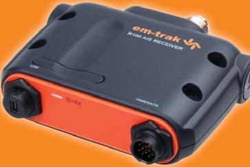
10 About your AIS receiver Fixing screws Two fixing screws are provided with the product for mounting of the AIS receiver. Please refer to section 3.2 for details of how to mount the AIS receiver. Accessory cable The accessory cable provides connections to the AIS receiver for power supply and NMEA0183 connections. USB cable The USB cable can be used to connect the AIS receiver to a PC. AIS receiver unit Figure 2 shows an overview of the AIS receiver unit. VHF antenna connector Mounting holes Mounting holes USB connector Indicator light Power and data Figure 2 AIS receiver overview Page 7
11 Installation 3 Installation 3.1 Preparing for installation Figure 3 shows a typical installation configuration for the AIS receiver. Please take the time to familiarise yourself with the system elements and their connections prior to attempting installation. Power in Optional PC NMEA0183 device VHF Antenna Chartplotter Dual channel AIS receiver Figure 3 Typical installation configuration Page 8
12 Installation In addition to the items provided with your AIS receiver the following items will be required for installation: VHF antenna Connection to a suitable VHF antenna will be required for the AIS receiver to operate. A standard marine band VHF antenna such as that used with VHF voice radios will be sufficient. Please take note of the warnings in section 1 regarding the use of antennas. Alternatively, if you wish to use an existing VHF antenna, antenna splitter products are available which allow the existing antenna to be used with two radio devices, such as a VHF voice radio and the AIS receiver. Antenna cables Please check that the VHF antenna you intend to use has sufficient cable to reach between the VHF antenna and the AIS receiver unit. If it is not sufficient you will need an extension cable. Please contact your dealer for details of suitable products. For reference the VHF antenna connector type on the AIS receiver unit is SO239, and is intended to mate with a PL259 connector. Power and data cables The AIS receiver unit is supplied with a two metre long power and data accessory cable. If you require longer cables to reach your power supply, please ensure the cables are capable of carrying an average current of up to 200mA. Means of connecting the cables together will also be required. The use of Scotchlok TM connectors is recommended for this purpose. Chart plotter To display received AIS position reports as other vessels on your chart plotter, you will need to connect your AIS receiver to your chart plotter. Please refer to the user manual supplied with your chart plotter for details of how to connect and configure your chart plotter for use with AIS devices. For general guidance your chart plotter should be configured to accept NMEA data at baud (sometimes referred to as 'NMEA HS' in the plotter configuration menu). You may also need to enable the display of AIS targets in the chart options. Step 8 - USB Connection (optional) The AIS receiver is supplied with a USB port for connection to a PC. The USB connector can be connected directly to the USB port on the PC via the supplied USB cable. To enable connection Page 9
13 Installation of the AIS receiver to a PC the USB drivers, supplied on the product CD, must be installed on the PC. Prior to connecting the AIS to a PC the USB drivers must first be installed. To install the drivers please follows the steps below: 1. Insert the product CD into the PC and navigate to the USB drivers folder. 2. Double click on the setup.exe file to launch the installer. 3. Follow the on screen installation instructions to complete installation. 4. Once installed the AIS receiver can be connected to the PC. The USB drivers will be installed automatically and the AIS will appear as a new COM port device. 5. Select the AIS COM port and a baud rate of 38,400 in PC based navigation software to make use of the AIS data. If the USB connection is removed from the PC during use you must reset the! connection before further use. to reset the connection, disconnect then reapply power to the AIS before closing and relaunching any PC applications using the USB connection. Finally, reconnect the USB cable between the PC and the AIS receiver. If required, the unit can be powered via the USB connection directly from the PC thus avoiding the need for a separate power supply connection. If this option is selected the power connection on the accessory cable should insulated to avoid being short circuited. Page 10
14 Installation 3.2 Installation procedures Before beginning installation of your AIS receiver, please ensure you have the necessary additional items as detailed in section 3.1. It is strongly recommended that you read all of the instructions in this manual prior to installation. If after reading this manual you are unsure about any element of the installation process please contact your dealer for advice. The following sections explain the installation process step by step for each of the main elements of the system. Step 1 - Installing the AIS receiver Please note the following guidelines when selecting a location for your AIS receiver: The AIS receiver must be fitted in a location where it is at least 0.5m from a compass. There should be adequate space around the AIS receiver for routing of cables. See Figure 4 for details of the AIS receiver dimensions. The ambient temperature around the AIS receiver should be maintained between -10 C and +55 C. The AIS receiver should not be located in a flammable or hazardous atmosphere such as in an engine room or near to fuel tanks. The AIS receiver is not designed to be waterproof and it is therefore not recommended that the AIS receiver be subjected to spray or submersion. It is recommended that the AIS receiver is installed in a 'below decks' environment. It is acceptable to mount the AIS receiver either vertically or horizontally. The product is supplied with four self tapping screws for attachment of the AIS receiver to a suitable surface. Please refer to Figure 4 for guidance. The AIS receiver should be mounted in a location where the indicator is readily visible as this provides important information on the status of the AIS receiver. Page 11
15 Installation 87.0 mm 37.0 mm 30.0 mm 87.2 mm mm Figure 4 AIS receiver dimensions and mounting Page 12
16 Installation Step 2 - Connecting the VHF antenna Route the cable from the VHF antenna to the AIS receiver and connect to the VHF connector on the AIS receiver as shown in Figure 5. A standard marine band VHF antenna or AIS antenna should be used with the AIS receiver. The connector type on the AIS receiver is SO239. Your chosen VHF antenna requires a PL259 connector to mate with this. If your VHF antenna does not use this type of connector please contact your dealer for details of available adaptors. VHF Antenna Figure 5 Position of the VHF antenna connector Step 3 - Connecting to a chart plotter or other NMEA0183 device The NMEA0183 data port provides the connection to your chart plotter and consists of four wires colour coded as shown in the table below and in Figure 6. Connect the two Transmit wires to the appropriate connections on your chart plotter. Please refer to your chart plotter manual for more information. The NMEA0183 data port output operates at a baud rate of baud. Please ensure your chart plotter is configured to receive data from the AIS receiver via its NMEA0183 port at baud. Page 13
17 Installation Please note that the 'Receive' connections should not normally be connected to your chart plotter as it is not normal for the receiver to receive data from the chart plotter. NMEA0183 function Transmit + (Output) Transmit - (Output) Receive + (Input) Receive - (Input) Wire colour Brown Blue White Green Step 4 - Connecting an optional NMEA0183 device If you wish to connect a NMEA0183 device (such as a heading sensor) to your chart plotter, but your chart plotter only has a single NMEA0183 input, it is possible to use the AIS receiver s NMEA0183 multiplexing feature to connect both devices to the chart plotter. To multiplex your NMEA0183 device data via the AIS receiver simply connect the device s NMEA0183 output to the receive + and receive - terminals as defined in the table above. The NMEA0183 input baud rate is 4800 baud. Please ensure your NMEA0183 device operates at 4800 baud. Page 14
18 Installation Red Black Light green Orange Brown Blue White Green Purple Pink Grey Yellow Power in + Power in - Not used Not used Transmit + Transmit Receive + Receive Not used Not used Not used Not used NMEA0183 Port Figure 6 Connecting to the NMEA0183 data port Connection to a PC The AIS receiver is supplied with a USB connector for connection to a PC via the USB cable provided. If your PC requires USB drivers to operate with the AIS receiver these can be found on the CD provided with the product. The AIS receiver can be powered via USB removing the need to have a separate power supply connection to the unit. No additional actions need to be taken other than to connect the USB cable as described. It is possible to connect both USB and an external power supply as described in step 4 below. In this instance the unit will automatically takes its power from the external supply. When inserting the USB connector into a PC for the first time, you are likely to be prompted to select the drivers for the USB device. Insert the CD provided with the product into the PC and Page 15
19 Installation select Search for drivers on this computer. Your PC should find the drivers located on the CD and install them on the PC. Please note: If you connect the USB connector to an alternative port on your PC this procedure may be repeated. The AIS receiver will appear as an additional COM port on your PC. This COM port should be selected as the AIS data source in charting applications. The port operates at baud. Step 4 - Connecting to a power supply The AIS receiver requires a 12V or 24V power supply typically provided by the vessel's battery. It is recommended that crimped and soldered lugs are used to connect the AIS receiver to the power source. It is recommended that the power supply is connected via a suitable circuit breaker and/or 1A fuse block. 1. Connect the red wire to the power supply positive terminal. 2. Connect the black wire to the supply negative terminal. Page 16
20 Installation. Figure 7 Red Black Light green Orange Brown Blue White Green Purple Pink Grey Yellow Connecting the power supply Power in + Power in Not used Not used Transmit + Transmit Receive + Receive Not used Not used Not used Not used NMEA0183 Port Page 17
21 Operation 4 Operation 4.1 Using the AIS receiver Once the unit has been installed it is ready for use. Providing other vessels with AIS transceivers installed are within radio range of your vessel you should see their details appear on your chart plotter or PC. Specific details of how to configure your chart plotter to make use of the AIS receiver features will be given in your chart plotter manual. If you are using charting software running on a PC, please refer to the instructions provided with your chart plotting software for details of how to configure it to display AIS information. 4.2 Indicator functions The AIS receiver includes a green indicator light as shown in Figure 8. The state of the indicator provides information regarding the status of the AIS receiver. The status indicator will illuminate when power is applied to the unit and it is running in normal mode. The brightness of the indicator will decrease on receipt of AIS messages. Indicator light Figure 8 Indicator location on the AIS receiver unit Page 18
22 Troubleshooting 5 Troubleshooting Issue No data is being received by the chart plotter The indicator is not illuminated The indicator is flashing but AIS targets are not displayed on the chart plotter The indicator is illuminated but not flashing to indicate receipt of AIS data Possible cause and remedy Check that the power supply is connected correctly, or if the unit is powered via USB check the PC is powered on. Check that the connections to the chart plotter are correct. Check that the VHF antenna is correctly connected in accordance with the instructions in the manual Check that the power supply is connected correctly, or if the unit is powered via USB check the PC is powered on. Check the chart plotter NMEA port configuration is set to receive AIS data Check the chart plotter display settings are configured to show AIS targets Consult the chart plotter manufacturers documentation Check there are vessels equipped with AIS transceivers in your area Check the VHF antenna is correctly installed and connected If the guidance given in the table above does not rectify the problem you are experiencing, please contact your dealer for further assistance. Page 19
23 Specifications 6 Specifications Parameter Value Dimensions 116 x 115 x 37.0 mm (L x W x H) Weight 120g (AIS receiver unit only) Power DC (9.6V V) Average power consumption 90mA at 12VDC Peak current rating 200mA Electrical Interfaces USB 2.0, baud bi-directional NMEA baud (output) 4800 baud (input) Connectors VHF antenna connector type: SO USB 12 way connector for NMEA0183 / Power Dual channel receiver Fixed frequency reception at MHz and MHz Channel Bandwidth 25kHz Receiver Sensitivity Better than -107dBm at 20% Packet Error Rate Environmental Operating temperature: -25ºC to +55ºC Ingress Protection rating IPx2 Page 20
24 Specifications Page 21
25
26 High Performance Maritime Products The em-trak R100 is an aid to navigation and must not be relied upon to provide accurate navigation information. AIS is not a replacement for vigilant human lookouts and other navigation aids such as Radar. The performance of the R100 may be seriously impaired if not installed as instructed in the user manual, or due to other factors such as weather and or nearby transmitting devices. Compatibility with other systems may vary and is reliant on the third party systems recognising the standard outputs from the R100. em-trak reserves the right to update and change these specifi cations at any time and without notice. Head Office: em-trak Marine Electronics Limited Forum 3, Parkway, Solent Business Park, Whiteley, Fareham, Southampton PO15 7FH United Kingdom T +44 (0) F +44 (0) enquiries@em-trak.com Regional Office: em-trak Marine Electronics Limited 470 Atlantic Avenue, 4th fl oor, Boston MA USA T F enquiries@em-trak.com
HIGH PERFORMANCE MARITIME. em-trak S100 PRODUCTS. Antenna splitter. Product Manual. High Performance Maritime Products
 em-trak S100 MARITIME PRODUCTS HIGH PERFORMANCE Antenna splitter Product Manual High Performance Maritime Products www.em-trak.com 201-0206:3 Contents 1 - Notices...1 1.1 - Safety warnings...1 1.2 - General
Thank you for buying this AIS antenna splitter.
 Thank you for buying this AIS antenna splitter. This product has been engineered to offer you the highest level of performance and durability and we hope that it will provide many years of reliable service.
Thank you for buying this AIS receiver.
 Thank you for buying this AIS receiver. This product has been engineered to offer you the highest level of performance and durability and we hope that it will provide many years of reliable service. We
Watcheye S AIS Splitter. manual
 Watcheye S AIS Splitter manual Thank you for buying this AIS antenna splitter. This product has been engineered to offer you the highest level of performance and durability and we hope that it will provide
NSPL-500. AIS/VHF antenna splitter. User Manual ENGLISH.
 NSPL-500 AIS/VHF antenna splitter User Manual ENGLISH www.bandg.com www.simrad-yachting.com www.lowrance.com Preface As Navico is continuously improving this product, we retain the right to make changes
ANTENNA SpliTTEr. Zero loss active VHF antenna splitter. I N s t r u c t i o n m a n u a l
 ANTENNA SpliTTEr Zero loss active VHF antenna splitter I N s t r u c t i o n m a n u a l w w w. g m e. n e t. a u Thank you for buying this AIS antenna splitter. This product has been engineered to offer
HIGH PERFORMANCE MARITIME. em-trak B100 PRODUCTS. AIS Class B Transceiver. Product Manual. High Performance Maritime Products
 em-trak B100 MARITIME PRODUCTS HIGH PERFORMANCE AIS Class B Transceiver Product Manual High Performance Maritime Products www.em-trak.com Contents 1 - Notices...1 1.1 - Safety warnings...1 1.2 - General
Watcheye B transponder manual
 Watcheye B transponder manual Thank you for buying this AIS Class B transceiver. This product has been engineered to offer you the highest level of performance and durability and we hope that it will provide
HIGH PERFORMANCE MARITIME PRODUCTS. em-trak B212 AIS Class B Transceiver. Product Manual. High Performance Maritime Products.
 em-trak B212 AIS Class B Transceiver MARITIME PRODUCTS HIGH PERFORMANCE Product Manual High Performance Maritime Products www.em-trak.com Thank you for buying this AIS Class B transceiver. This product
Watcheye B Pro AIS Class B Transponder. manual
 Watcheye B Pro AIS Class B Transponder manual Thank you for buying this AIS Class B transceiver. This product has been engineered to offer you the highest level of performance and durability and we hope
Metadata MDA-5 Class B AIS Transceiver /Splitter Installation & Operation Manual
 Metadata MDA-5 Class B AIS Transceiver /Splitter Installation & Operation Manual Thank you for buying this AIS Class B transceiver. This product has been engineered to offer you the highest level of performance
TX AIS Installation and Operations Manual ACCESSORY MANUAL
 TX AIS Installation and Operations Manual ACCESSORY MANUAL Thank you! Thank you for choosing Humminbird, the #1 name in marine electronics. Humminbird has built its reputation by designing and manufacturing
High performance marine products. em-trak B360. Class B AIS Transceiver. Product manual. High Performance Marine Products.
 High performance marine products HIGH MAR PER PRO FOR MAN ITIM DUC TS CE E em-trak B360 Class B AIS Transceiver Product manual High Performance Marine Products www.em-trak.com Thank you for buying this
em-trak B330 Product manual anual High Performance Marine Products
 HIGH MAR PERF ORM ANCE ITIME PRO DUCT S em-trak B330 Class B AIS ST Tra Tr Transceiver ra ansceiver ansceiv ver Product manual anual High Performance Marine Products www.em-trak.com Thank you for buying
HIGH PERFORMANCE MARITIME. em-trak B100 PRODUCTS. Product Manual.
 em-trak B100 MARITIME PRODUCTS HIGH PERFORMANCE Product Manual www.em-trak.com Contents 1 - Notices...1 1.1 - Safety warnings...1 1.2 - General notices...1 2 - About your AIS class B transceiver...6 2.1
SAR TX1. AIS SEARCH AND RESCUE TRANSMITTER User Manual
 SAR TX1 AIS SEARCH AND RESCUE TRANSMITTER User Manual Contents 1 - Notices...2 1.1 - Safety warnings...2 1.2 - General notices...2 2 - About your AIS SART...5 2.1 - About AIS...5 2.2 - What s in the box...6
NAIS-500 Class B AIS Transceiver. User Manual ENGLISH.
 NAIS-500 Class B AIS Transceiver User Manual ENGLISH www.bandg.com www.simrad-yachting.com www.lowrance.com Preface As Navico is continuously improving this product, we retain the right to make changes
Class B AIS Transceiver Mariner X2 Automatic Identification System
 Class B AIS Transceiver Mariner X2 Automatic Identification System INSTALLATION MANUAL Version 1.4 Thank you for buying this AIS Class B transceiver. This product has been engineered to offer you the highest
Thank you for buying this AIS Class B transceiver.
 Thank you for buying this AIS Class B transceiver. This product has been engineered to offer you the highest level of performance and durability and we hope that it will provide many years of reliable
Murata Bluetooth mesh Node. Installation Guide
 Murata Bluetooth mesh ode Installation Guide Shipped Components Murata Bluetooth mesh ode (BCC2ZZ1PR) ocknut Page 1 Caution Installation and maintenance must be done in accordance with local, state and
User s Manual Wireless Keyboard/Mouse & NANO Receiver MD-5110/MM-5110 & DG-5110
 User s Manual Wireless Keyboard/Mouse & NANO Receiver MD-5110/MM-5110 & DG-5110 Page 1 of 7 FCC Statement This equipment has been tested and found to comply with the limits for a Class B digital device,
16+ HS300. Instructions for use. One Key Start/One Key Landing Function Headless Mode / One Key Return Altitude Hold Mode
 16+ HS300 Instructions for use One Key Start/One Key Landing Function Headless Mode / One Key Return Altitude Hold Mode usa@holystone.com ca@holystone.com By scanning the QR code or searching Holy Stone
User Manual. NAIS-400 Class B AIS Transceiver. ENGLISH
 NAIS-400 Class B AIS Transceiver User Manual ENGLISH www.bandg.com www.simrad-yachting.com www.lowrance.com Preface As Navico is continuously improving this product, we retain the right to make changes
LOUIS VUITTON 1. Louis Vuitton Echo, locate your Horizon luggage in airports Battery indicator light. Light sensor to detect opening
 L E A F L E T - Louis Vuitton Echo, locate your Horizon luggage in airports Battery indicator light Light sensor to detect opening ON/OFF switch Micro-USB port for charger 3. Open LV PASS. Go to Connected
CARE +MAINTENANCE Cleaning Important Safety Instructions Water Drop Heat Battery Charging Repair
 CARE +MAINTENANCE Cleaning 1. Wipe with a dry cloth. 2. Rinse with fresh water after exposure to soap, chlorine or seawater. 3. Do not use solvents, chemicals, cleaning solutions, alcohol, ammonia or abrasives.
Polycom VoxBox Bluetooth/USB Speakerphone
 SETUP SHEET Polycom VoxBox Bluetooth/USB Speakerphone 1725-49004-001C Package Contents Micro USB Cable 1.21 m 4 ft Carrying Case Security USB Cable 3 m 10 ft L-Wrench Optional Accessories Security USB
Transponder Reader TWN4 MultiTech 3 Quick Start Guide
 Transponder Reader TWN4 MultiTech 3 Quick Start Guide Rev. 1.0 1. Introduction The transponder reader TWN4 is a device for reading and writing RFID transponders. There are different versions of TWN4 devices
Link Mobile Gateway User Guide A ProVIEW System Component
 A ProVIEW System Component Omni-ID office locations: US UK China India Southeast Asia Germany 1. CONTENTS 1. Introduction... 3 About this Document... 3 Related Products... 3 Regulatory Approvals... 4 Certifications...
Vehicle IoT Gateway VG34 DATASHEET OVERVIEW HIGHLIGHTS
 Vehicle IoT Gateway VG34 DATASHEET OVERVIEW The VG34 Vehicle IoT Gateway is an advanced sensor platform for fleets, providing operators with real-time location and analytics, sensor data, WiFi hotspot
APM 6998 WiFi Module Manual
 Host Revision Information APM 6998 WiFi Module Manual Host Hardware Revision Host Module Driver Version Module Hardware Revision T3x Rev D1 v8.1.4.4 001E Host PCB Design Guidelines The following guidelines
User guide. SmartTags. NT3/SmartTagsST25a
 User guide SmartTags NT3/SmartTagsST25a Contents Introduction...3 What are SmartTags?... 3 Getting started... 4 Turning on the NFC function... 4 NFC detection area... 4 Smart Connect... 4 Using SmartTags...
General Safety and Precautions 1. Read all of the information in the owner s manual and other included product information in the packaging before
 General Safety and Precautions 1. Read all of the information in the owner s manual and other included product information in the packaging before operating the product. 2. Prolonged exposure to alarm
ACUII-06 User Manual (NAS)
") 1(14) ACUII-06 User Manual (NAS) Content 2(14) 1 General... 3 1.1 history... 3 1.2 Abbreviations... 3 1.3 References... 3 2 Introduction... 4 3 Technical Description... 5 3.1 Connectors... 5 3.1.1 WLAN
1(14) ACUII-06 User Manual (NAS) Content 2(14) 1 General... 3 1.1 history... 3 1.2 Abbreviations... 3 1.3 References... 3 2 Introduction... 4 3 Technical Description... 5 3.1 Connectors... 5 3.1.1 WLAN
MOVADO.COM/SMARTSUPPORT
 LANGUAGES ENGLISH... 3 FRANÇAIS... 4 ESPAÑOL... 5 REGULATORY INFORMATION... 6 MOVADO CONNECT POWERED BY ANDROID WEAR DOWNLOAD THE APP & GET STARTED AT MOVADO.COM/SMARTSUPPORT 3 MOVADO CONNECT POWERED BY
260X190mm/105 克铜版纸 / 黑白印刷
 260X190mm/105 克铜版纸 / 黑白印刷 5172301 1 FEATURES A-Control Panel A1-Bass Volume Adjustment A2-Volume Adjustment A3-Audio Input Jack A4-Audio Output Jack for linking multiple chairs A5-Wire mode / Bluetooth
User Manual. 1. Introduction. 2. Features
 1. Introduction User Manual AMPAK Technology would like to announce a low-cost and low-power consumption module which has all of the WiFi and Bluetooth functionalities. The highly integrated module makes
DCH-G020 mydlink Connected Home Hub
 DCH-G020 mydlink Connected Home Hub User s Manual Version 01.0 Oct. 15 th, 2014 Manual Page 1 10/16/2014 1. PRODUCT DESCRIPTION The DCH-G020 is a Connected Home Z-Wave Gateway used to control a variety
Need Help? SA /
 1 FEATURES A-Control Panel A1-Vibration adjustment A2-Bass Volume Adjustment A3-Volume Adjustment A4-Audio Input Jack A5-Audio Output Jack for linking multiple chairs A6-Wire mode / Bluetooth mode Switch
testosaveris 2 User Manual testo Saveris 2Introduction
 testosaveris 2 User Manual testo Saveris 2Introduction testo Saveris 2 system is upgrading product basing on testo Saveris system. In original system, wireless probes transfer measurement data to Saveris
or call
 Email service@acecasual.com or call 1 FEATURES A-Control Panel A1-Vibration adjustment A2-Bass Volume Adjustment A3-Volume Adjustment A4-Audio Input Jack A5-Audio Output Jack for linking multiple chairs
User Manual. 1. Introduction. 2. Features
 1. Introduction User Manual AMPAK Technology would like to announce a low-cost and low-power consumption module which has all of the Wi-Fi functionalities. The highly integrated module makes the possibilities
Shields. Outdoor Shields Owner s Manual. Avoidance Solutions.
 Shields Avoidance Solutions Outdoor Shields Owner s Manual www.invisiblefence.com Important Precautions Invisible Fence Brand systems have protected over two million pets. However, there are some precautions
Icon Description UP ( ) 1 BACK ( ) 4 PAGE ( )
 1 BACK ( ) 4 PAGE ( )") EN 1 1 BACK ( ) Press to return to the previous page or cancel an operation. When recording, press to pause recording. Press it again to stop recording. 2 LAP/OK ( ) In Menu, press to enter or confirm
EN 1 1 BACK ( ) Press to return to the previous page or cancel an operation. When recording, press to pause recording. Press it again to stop recording. 2 LAP/OK ( ) In Menu, press to enter or confirm
5.8G Wireless Audio Transceiver/Receiver Module DWHP83
 5.8G Wireless Audio Transceiver/Receiver Module DWHP83 1. Module dimensions and layout 2. Antenna info Brand: EDIFIER Antenna type: PCB Max Peak gain: 5.36 dbi 3. Feature: DARR83 Wireless Audio Processor
Regulatory Compliance Statement
 Regulatory Compliance Statement EU Declaration of Conformity The declaration of conformity may be consulted at www.kobo.com/userguides SAR Limits The exposure standard for wireless devices employs a unit
Pser G uide oduct Manual
 ADC-T2000 Hub User Product Guide Manual Hub Product Manual 1 Set Up Required Standard home router with active Internet connection Z-Wave devices to be installed Indicator Lights White Flashing: no internet
Alcatel-Lucent 8340 Smart IP-DECT AP. Installation Manual
 8AL90850USBAed01-10/2013 Alcatel, Lucent, Alcatel-Lucent and the Alcatel-Lucent logo are trademarks of Alcatel- Lucent. All other trademarks are the property of their respective owners. The information
OPERATION MANUAL WARNING
 TM OPERATION MANUAL WARNING TO REDUCE THE RISK OF INJURY OR PRODUCT DAMAGE, READ OPERATION MANUAL PRIOR TO OPERATING PRODUCT. PATENT PENDING - COPYRIGHT 2014 - APPION INC. - ALL RIGHTS RESERVED Introduction
Regulatory Compliance and Important Safety Information
 Regulatory Compliance and Important Safety Information Regulatory Certification/Approval Marks for your device can be found in Settings > About Kobo Glo HD EU Declaration of Conformity A copy of the EU
BT11 Hardware Installation Guide
 Overview The Mist BT11 delivers a BLE Array AP with internal antennas that are used for BLE based location. 1 Understanding the Product Included in the box: BT11 Mounting bracket with mounting hardware
Evaluation Kit ATA8520-EK1-F and Extension Board ATA8520-EK3-F (US Version) Kit Content ATAN0157 APPLICATION NOTE
 Kit Content ATAN0157 APPLICATION NOTE") ATAN0157 Evaluation Kit ATA8520-EK1-F and Extension Board ATA8520-EK3-F (US Version) APPLICATION NOTE Kit Content The ATA8520-EK1-F kit includes the following components: Standalone board 902MHz antenna
ATAN0157 Evaluation Kit ATA8520-EK1-F and Extension Board ATA8520-EK3-F (US Version) APPLICATION NOTE Kit Content The ATA8520-EK1-F kit includes the following components: Standalone board 902MHz antenna
Blue Node. User Manual
 Blue Node User Manual CONTACT US LX Suite 101, 4 Cornwallis St, Eveleigh, 2015 National Innovation Centre Australian Technology Park Sydney, Australia +612 9209 4133 IoTCores.com.au LX IoT Cores Blue Node
Manual Unihan UPWL6024
 Manual Unihan UPWL6024 Federal Communications Commission Statement This device complies with FCC Rules Part 15. Operation is subject to the following i. This device may not cause harmful interference,
GNSS multiconstellation, GPS+Glonass as a minimum; GSM; Accelerometer; SIM on Chip; Watch Dog; Power Management; RF transceiver; CAN Bus interface
 ZTE AT21 User Guide 1.1 Reference Architecture The reference architecture of the Kernel module is shown here below The main HW architecture features and physical constraints are summarized below: GNSS
DOWNLOAD KASA ADD TO KASA INSTALL AND POWER UP SAFETY FIRST
 WELCOME TO KASA Let s get started with your new Wi-Fi Smart Dimmer. Kasa SAFETY FIRST Read and follow all safety precautions in the Kasa app. Ensure power is off at the circuit breaker before removing
Electronic Emission Notices
 Electronic Emission Notices - - - - - - - - - - - - - - - - - - - - - - - - - - - - - - - - - - - - - - - - - - - - - - - - - - - - - - The following information refers to the Lenovo Active pen. Federal
AIT2000 CLASS B AIS TRANSPONDER
 IMPORTANT NOTE The USB cable of the AIT2000 is designed to be used for configuring/programming the unit during installation and not for permanent connection to the boat s Navigation PC. If you intend to
AIS 300 Installation Instructions
 Use these instructions to install the Garmin AIS 300 Automatic Identification System (AIS) Class B receiver device. Compare the contents of this package with the packing list on the box. If any pieces
FCC Certification Notice: IC Certification
 Users Manual VP4450 FCC Certification This device complies with Part 15 of the FCC Rules. Operation is subject to the following two conditions: (1) This device may not cause harmful interference, and (2)
EE1941/EN1941 One-Way Binary RF Module Installation and Operation Manual D
 EE1941/EN1941 One-Way Binary RF Module nstallation and Operation Manual - 06287D 1 Overview EchoStream RF modules are designed to be easily interfaced with your electronic remote application controller
FOR AVLEX ONLY MT-24A. User Guide. 2.4 GHz Digital Stationary Transmitter
 2.4 GHz Digital Stationary Transmitter User Guide All rights reserved. MN 017/05 Do not copy or forward without prior approvals MIPRO. Specifications and design subject to change without notice. 2 CE5
802.11a/n/b/g/ac WLAN Module AMB7220
 AboCom 802.11a/n/b/g/ac WLAN Module AMB7220 User s Manual FCC Certification Federal Communication Commission Interference Statement This equipment has been tested and found to comply with the limits for
800 Series Transmitters Owner s Manual
 800 Series Transmitters Owner s Manual www.invisiblefence.com www.invisiblefence.com Important Precautions Invisible Fence Brand pet containment systems have contained over two million pets. However, there
StreamStick by NAV-TV is a USB-powered, HI-FI Bluetooth 4.0 audio streaming module for automotive and home use. Make ANY stereo (equipped with AUX
 StreamStick by NAV-TV is a USB-powered, HI-FI Bluetooth 4.0 audio streaming module for automotive and home use. Make ANY stereo (equipped with AUX input) a Bluetooth-audio receiver! Using the StreamStick
ihealth Wireless Body Analysis Scale OWNER S MANUAL
 ihealth Wireless Body Analysis Scale OWNER S MANUAL TABLE OF CONTENTS INTENDED USE... 2 IMPORTANT NOTE FOR USERS... 2 CONTRAINDICATION... 2 OFFLINE MEMORY... 3 SPECIFICATIONS... 3 GENERAL SAFETY AND PRECAUTIONS...
User Guide. Do not copy or forward without prior approvals MIPRO. Specifications and design subject to change without notice.
 User Guide ACT-70H / ACT-71Ha ACT-71H / ACT-72H All rights reserved. MN 016/01 Do not copy or forward without prior approvals MIPRO. Specifications and design subject to change without notice. 2 CE5 2
Installation & Quick Start Guide AIT2000 Class B AIS Transponder
 Installation & Quick Start Guide AIT2000 Class B AIS Transponder QUICK START AIT2000 - VR1.01 1. Introduction Congratulations on the purchase of your AIT2000 Class B AIS Transponder. It is recommended
NV-WA40W. Installation and User Guide
 NV-WA40W Installation and User Guide Introduction The NV-WA40W-AMP is a versatile 40-watt in wall zone amplifier perfectly suited to a variety of tasks. Its design allows two line level sources to be permanently
PA421B PA821B. Front Panels. Included Components. Features. Model Variations. Antenna Combiner
 Antenna Combiner WARNING: This product contains a chemical known to the State of California to cause cancer and birth defects or other reproductive harm. General Description Shure antenna combiners actively
Installation & Quick Start Guide CLB2000 Class B AIS Transponder
 Installation & Quick Start Guide CLB2000 Class B AIS Transponder QUICK START CLB2000 - VR1.01 1. Introduction Congratulations on the purchase of your CLB2000 Class B AIS Transponder. It is recommended
INSTALLATION MANUAL ES-SUB-WIRELESS-KIT ES-SUB-WIRELESS-RCVR
 INSTALLATION MANUAL ES-SUB-WIRELESS-KIT ES-SUB-WIRELESS-RCVR FCC STATEMENT This equipment has been tested and found to comply with the limits for a Class B digital device, pursuant to Part 15 of the FCC
High performance Marine Products Automatic Identification System
 www.em-trak.com High performance Marine Products Automatic Identification System High performance marine products PRODUCTS APPLICATIONS ABOUT em-trak products are engineered to provide the best performance
SYSTEM REQUIREMENTS (Windows) Windows XP(Service Pack 2 or later) or vista 3.2GHz Pentium 4 or faster Minimum 1GB of system RAM
 Windows XP(Service Pack 2 or later) or vista 3.2GHz Pentium 4 or faster Minimum 1GB of system RAM") CGO2 User Manual TABLE OF CONTENTS System requirements(windows) System requirements(mac) Technical specifications Introduction Overview Getting started Default camera settings Powering ON and OFF Camera
CGO2 User Manual TABLE OF CONTENTS System requirements(windows) System requirements(mac) Technical specifications Introduction Overview Getting started Default camera settings Powering ON and OFF Camera
6505 MICRO. Amplifier. Operating Manual.
 6505 MICRO Amplifier Operating Manual www.peavey.com FCC/ICES Compliancy Statement This device complies with Part 15 of the FCC rules and Industry Canada license-exempt RSS Standard(s). Operation is subject
EA200 uhf EA200 vhf User Guide
 EA200 uhf EA200 vhf User Guide 1 2 TABLE OF CONTENTS RF Safety & FCC... 4 Safety & Information... 5 Electromagnetic Interference Compliance... 6 Industry Canada Compliance... 7 Computer Software Copyrights...
System overview. be connected: Components that can. 1. OKIMAT IPS OM Massage motor. 7. Optional: Junction cable
 System overview Notice! Electrical components should be connected or disconnected only when the powerr supply cord is unplugged. Notice! There is a delay after the supply voltage is applied before the
HOBO RX Wireless Sensor Network HOBO RXW Repeater (RXW-RPTR-xxx) Manual
 Manual") Test Equipment Depot - 800.517.8431-99 Washington Street Melrose, MA 02176 - TestEquipmentDepot.com HOBO RX Wireless Sensor Network HOBO RXW Repeater (RXW-RPTR-xxx) Manual The HOBO RXW Repeater is designed
Test Equipment Depot - 800.517.8431-99 Washington Street Melrose, MA 02176 - TestEquipmentDepot.com HOBO RX Wireless Sensor Network HOBO RXW Repeater (RXW-RPTR-xxx) Manual The HOBO RXW Repeater is designed
1. Open Mi Drone APP, select Next button. 1. Connect MiRC_XXXXXX device, the default key is
 1. Open Mi Drone APP, select Next button. 1. Connect MiRC_XXXXXX device, the default key is 123456789. 2. Select Wi-Fi connection on the dialog box, tap OK button. 2. Back to Mi Drone APP, APP will complete
12V Victor 888 User Manual
 The Victor speed controllers are specifically engineered for robotic applications. The high current capacity, low voltage drop, and peak surge capacity make the Victor ideal for drive systems while its
FOR TRAINING PURPOSES ONLY DATED MATERIAL. Aperio Hub AH20/AH30 Installation Instructions. ASSA ABLOY, the global leader in door opening solutions
 perio Hub H20/H30 Installation Instructions Covers WL-260 3 May 2011 SS LOY, the global leader in door opening solutions 1 H20/H30 - Table of Contents 2 H20/H30 - FCC and Industry Canada Statements 3 H20/H30
ISTATION-N (Integration Station) User Manual
 User Manual") ISTATION-N (Integration Station) User Manual HME Wireless, Inc Customer Service 800.925.8091 1400 Northbrook Parkway Suite #320 Suwanee, GA 30024 HME 800.925-8091 Integration Station Serial Transmitter
ISTATION-N (Integration Station) User Manual HME Wireless, Inc Customer Service 800.925.8091 1400 Northbrook Parkway Suite #320 Suwanee, GA 30024 HME 800.925-8091 Integration Station Serial Transmitter
MorningLinc INSTEON Morning Industry RF Doorknob/Deadbolt Controller
 MorningLinc INSTEON Morning Industry RF Doorknob/Deadbolt Controller Model : 2458A1 MorningLinc Owner s Manual MorningLinc Owner s Manual TABLE OF CONTENTS ABOUT MORNINGLINC... 2 Key MorningLinc Features...
EE1941/EN1941 One-Way Binary RF Module Installation and Operation Manual E
 EE1941/EN1941 One-Way Binary RF Module nstallation and Operation Manual - 06287E 1 Overview EchoStream RF modules are designed to be easily interfaced with your electronic remote application controller
MS1000 User Information MS1000-H systems equipped with MX900 Micro Transceiver will Send and Receive.
 MS1000 User Information MS1000-H systems equipped with MX900 Micro Transceiver will Send and Receive. The MS1000 is an AC or DC powered Micro Receiver System designed to send and receive signaling data
User s Manual COPYRIGHT DISCLAIMER
 COPYRIGHT The entire contents of this instruction manual, including any future updates, revisions, and modifications, shall remain the property of AMEC at all times. Unauthorized copies or reproduction
TomTom Touch Fitness Tracker User Manual
 TomTom Touch Fitness Tracker User Manual Contents Addendum 3 2 Addendum Warnings & Indications for use Indications for use TomTom Touch Fitness Tracker tracks Body Composition (body fat and muscle mass),
EE1941XS/EN1941XS One-Way Serial RF Module Installation and Operation Manual
 EE1941XS/EN1941XS One-Way Serial RF Module Installation and Operation Manual 1 Overview EchoStream RF modules are designed to be easily interfaced with your electronic remote application controller (RAC).
2011 Shure Incorporated 27A15021 (Rev. 2) *27A15021* Printed in China
 *27A15021* Printed in China") TM ShowLink TM Wireless Access Point 2011 Shure Incorporated 27A15021 (Rev. 2) *27A15021* Printed in China ShowLink Access Point The ShowLink access point enables real-time remote control of the Axient
TM ShowLink TM Wireless Access Point 2011 Shure Incorporated 27A15021 (Rev. 2) *27A15021* Printed in China ShowLink Access Point The ShowLink access point enables real-time remote control of the Axient
FMT4R FM Transmitter User s manual
 FMT4R FM Transmitter User s manual Contents 1. Overview.....1 2. Getting started 1 3. Basic operation...2 4. Care and maintenance...3 5. Frequently asked questions....3 6. Technical parameter..4 It is
Wireless Compliance Statements
 Wireless Compliance Statements Visual Coaching Device 13485 P1015323-001-A DECEMBER 2015 Document ID Document Title Abstract Manufacturer P1015323-001-A Wireless Compliance Statements Visual Coaching Device
Illuminati Wireless Light and Color Meter Model IM100. User Manual
 Illuminati Wireless Light and Color Meter Model IM100 User Manual About the IM100 The Illuminati IM100 is the world s first Bluetooth-enabled wireless light and color meter. Use it with your smartphone
StreetSounds STS-170-MMST Mobile Master. User Guide
 StreetSounds STS-170-MMST Mobile Master User Guide V1.4 June 3, 2018 1 CONTENTS 1 Introduction... 3 1.1 Mobi Front Panel... 3 1.2 Mobi Rear Panel... 4 1.3 Operating the Mobi... 4 2 FCC Statements... 6
User Manual. MITSUMI WiFi Module MODEL DWM-W081
 Page 1 of 7 User Manual MITSUMI WiFi Module MODEL DWM-W081 The purpose of this manual is to explain correct way how to integrate module DWM-W081 to the end product. It includes procedures that shall assist
Indoor Micro Shields Owner s Manual. Please read this entire guide before operating.
 Indoor Micro Shields Owner s Manual Please read this entire guide before operating. Important Precautions Invisible Fence Brand pet containment systems have contained over two million pets. However, there
SATELLITE RADIO OWNER'S MANUAL. Type III Radio
 SATELLITE OWNER'S MANUAL Type III Radio Table of Contents Congratulations!... 3 Operational Statement... 3 FCC Statement... 4 Activating Your Subscription... 5 Type III Radio... 6 Overview of Controls...
EE1941/EN1941/EN One-Way Binary RF Module Installation and Operation Manual
 EE1941/EN1941/EN1941-60 One-Way Binary RF Module Installation and Operation Manual 1 Overview EchoStream RF modules are designed to be easily interfaced with your electronic remote application controller
TABLE OF CONTENTS. PixMob Broadcaster 1
 TABLE OF CONTENTS 1- PixMob HUB Page 2 2- FCC Statements Page 4 3- IC Statements Page 5 4- Installation Page 6 5- Hub menu s Page 7 6- Troubleshooting Page 10 7- Hub characteristics Page 10 1 1. PixMob
HistoCore SPECTRA CV. RFID-Registration Registro de RFID Registro RFID تسجيل التعريف عن طريق الترددات الالسلكية
 HistoCore SPECTRA CV RFID-Registration Registro de RFID Registro RFID تسجيل التعريف عن طريق الترددات الالسلكية Version 1.1, Revision B 08.2018 RFID-Registration HistoCore SPECTRA CV Order No.: 14 0514
PowerView Remote Control Guide
 FRONT: OPEN Group 3 Group 4 Group 2 Group 5 LEFT ARROW Sends the middle rail DOWN on Top-Down/Bottom-Up or Duolite products Group 1 Group 6 RIGHT ARROW Sends the middle rail UP on Top-Down/Bottom-Up or
SwingTracker User Guide. Model: DKST02 User Guide
 SwingTracker User Guide Model: DKST02 User Guide PACKAGE CONTENTS What Comes in the Box USING YOUR SWINGTRACKER SENSOR Attach SwingTracker Sensor to your Bat Turn On your Sensor Pair your Sensor Remove