General Information Manual Edition 1.08
|
|
|
- Albert Harrington
- 5 years ago
- Views:
Transcription

1
2 General Information Manual Edition 1.08 i. Copyright The entire contents of this instruction manual, including any future updates, revisions, and modifications, shall remain the property of AMEC at all times. Unauthorized copies or reproduction of this manual, either in part or whole, in any form of print and electronic media, is prohibited. The contents herein can only be used for the intended purpose of this manual. ii. Disclaimer AMEC is devoted to publish and maintain this product manual. As we continue to improve our AIS products to satisfy all customers needs, information in this document is subject to change without notice. AMEC does not make any representations or warranties (implied or otherwise) regarding the accuracy and completeness of this document and shall in no event be liable for any loss of profit or any commercial damage, including but not limited to special, incidental, consequential, or other damage. I
3 iii. Safety Warning It is important to know that AIS is designed for the purpose of anti-collision and serves as a complement to navigation. It is not the absolute navigational equipment and does not replace any navigational system installed on board. Any AIS device cannot guarantee monitoring and receiving signals from all vessels in the surroundings unless those vessels are equipped with AIS devices. ELECTRICAL SHOCK HAZARD Improper disassemble or modification could cause electrical shocks, fire, or personal injury. Only qualified personnel could work on the interior of the equipment. CORRECT POWER SOURCE An incorrect power sources will damage the equipment and may even result in fire. Ensure the correct power input on the adaptor before installation. II
4 AVOID DIRECT CONTACT WITH RAIN OR SPLASHING WATER Electrical shock or fire could be resulted if water leaks into the equipment. AVOID USING CHEMICAL SOLVENTS TO CLEAN THE CASE As some solvents can damage the case material. NOTE/INFORMATION Important notices and information will be noted in this Installation and Operation Manual iv. Product Category This product is categorized as protected in accordance with the requirements as defined in IEC v. Disposal Instruction Do not dispose of this device with unsorted waste. Improper disposal may be harmful to the environment and human III
5 health. Please refer to your local waste authority for information on return and collection systems in your area. vi. Contact Information For sales, services, and technical supports, please contact your local AMEC representatives or Alltek Marine Electronics Corp at or IV
6 Table of Content 1 INTRODUCTION CYPHO-150 Overview Comparison of CYPHO-150 Series Type of AIS AIS Message Type About This Manual Important Notice GETTING STARTED Items in the Package Power ON / OFF CYPHO-150 LED Indicators CYPHO-150S LED Indicators INSTALLATION CYPHO-150 Connection Interface CYPHO-150S Connection Interface Installation Precautions Mounting Instructions Wiring Instructions VHF Antenna Installation Antenna Cabling USB Driver Installation CYPHO Configuration Software Software Installation Configuration i
7 3.9.3 Diagnosis NMEA 0183 Multiplexer AMEC AIS Viewer Software Installation APPENDIX Product Specifications Dimensions Accessories (Optional) FCC INTERFERENCE STATEMENT DECLARATION OF CONFORMITY ACRONYMS 54 ii
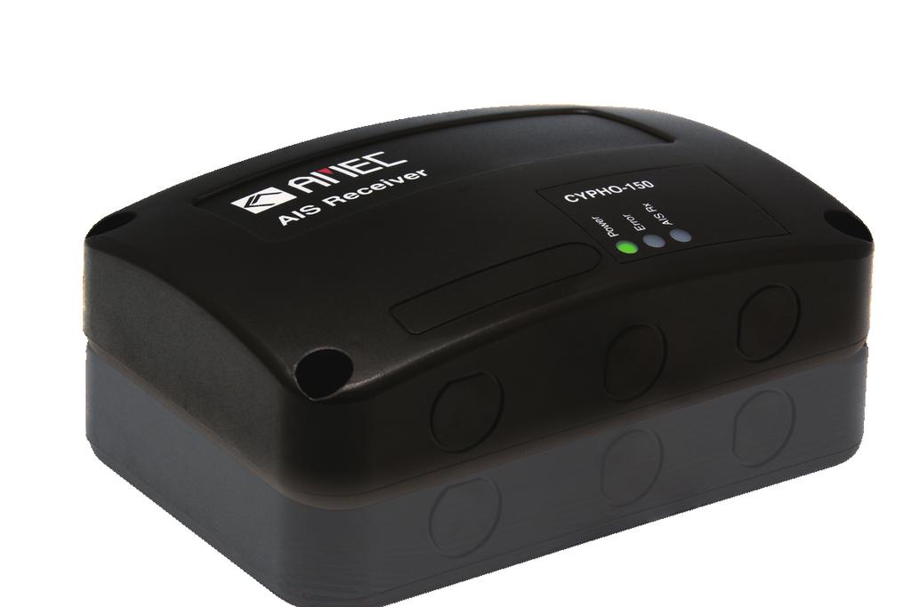
8 1 INTRODUCTION 1.1 CYPHO-150 Overview The AMEC CYPHO-150 (any CYPHO-150 model) is an AIS receiver series. It receives AIS navigation data from AIS-equipped vessels nearby and improves navigation safety. CYPHO-150 series is designed to inter-operate with AIS Class A or Class B transponders, and any other AIS station operating on the AIS VHF data link. CYPHO-150 series is built with two parallel AIS receivers in one box monitoring the default marine VHF AIS channels, i.e and MHz with optimized sensitivity. Having CYPHO-150 series AIS receiver on board, not only can you monitor the status of the vessels in the surrounding area, but also receive the dynamic information (position, speed, SOG, etc.), static information (ship name, MMSI, call sign, etc.), and voyage related information (cargo type, destination, etc.) from any vessels nearby that are equipped with AIS transponders. 1


9 Equipped with standard USB and NMEA0183, CYPHO-150 series allows connectivity to most available peripherals in the market. Users are able to view AIS information on their preferred PC based navigation systems via the USB interface. CYPHO-150 series is IPX2 water resistant providing acceptable protection against water. But it does require a protected installation environment away from water. Figure 1 CYPHO-150 2
10 1.2 Comparison of CYPHO-150 Series Description CYPHO-150 CYPHO-150S Number of AIS Channels 2 2 USB port 1 1 NMEA 0183 Built-in AIS splitter Independent 1 input, 1 output Independent 1 input, 1 output Yes 3
11 1.3 Type of AIS The different types of AIS devices are described below. The CYPHO-150 is the name of an AIS receiver series. Class A AIS Transponder Class B AIS Transponder AIS Receiver Transmits and receives AIS signal. Intended for vessels meeting the requirements of IMO AIS carriage requirement. It is mandatory for all commercial vessels that exceed 300 tons to be equipped with Class A AIS. Transmits and receives AIS signal. Not necessarily in full accord with IMO AIS carriage requirements. It is not mandatory for vessels to be equipped with Class B AIS. Suitable for recreational vessel, in enhancing its safety at sea. Only receives AIS signal. Does not have transmitter to send out AIS signal. Suitable for recreational vessel that does not want to send out its vessel information. 4
12 1.4 AIS Message Type The CYPHO-150 models can receive AIS messages from both Class A and Class B AIS transponders as well as from AIS Base Station, AIS AtoN, and AIS SART/MOB. The message types are listed as below table. The messages in gray color are transmitted only from class A AIS device. Type of Message Static Data Data Details Maritime Mobile Service Identity (hereinafter called MMSI ) number IMO number Call sign and name Type of ship Length and beam GPS Antenna location 5
13 Voyage Related Data Dynamic Data Dynamic Reports SRM Draught of the ship Cargo information Destination Estimate Time of Arrival (hereinafter called ETA ) Position of the vessel Coordinated Universal Time (hereinafter called Time in UTC.) Course Over Ground (hereinafter called COG ) Speed Over Ground (hereinafter called SOG ) Heading Rate of turn Navigational status Speed of the ship Status of the ship Alarm Safety 6
14 1.5 About This Manual The manual contains installation instructions and operating information for both CYPHO-150 and CYPHO-150S. While most of the installation can be performed by the owner or the crew, a final commissioning can be done by your local agent/dealer when needed or required. AMEC and the local agent/dealer will not bear any responsibilities over any damages resulted in improper installation by unauthorized agent/dealer. 7
15 1.6 Important Notice The intended use of the AMEC CYPHO-150 Series Automatic Identification System Receiver is to enhance the safety of vessels at sea. However, a few points must be addressed: Under certain regulations, some specified vessels are compulsory to be installed with AIS. However, this does NOT mean that all vessels will be equipped with AIS. Any AIS will NOT guarantee to monitor and to receive signals from every ship in the surroundings. AIS acts as aids to navigation in the purpose of decreasing or preventing the possibility of vessel collision. It is not the absolute navigational equipment and does not replace any navigational system installed on board. This product is a marine AIS receiver intended for worldwide use on NON SOLAS vessels. 8


16 2 GETTING STARTED 2.1 Items in the Package Please contact your supplier immediately if there is any item missing. No. Diagram Description Qty CYPHO-150 AIS Receiver series 1 150S 9
 1 3 User s Manual 1 4")
 1 5")

17 2 Power/USB/ NMEA0183 Cable, 1m (Wired to the unit) 1 3 User s Manual 1 4 CD-ROM (User s manual in digital format, Configuration Utility, USB driver ) 1 5 Mounting screws 4 M3.5x S only VHF cable, 1m (with PL-259 male connectors) 1 10
18 2.2 Power ON / OFF All CYPHO-150 models are designed having no physical On/Off switch. Thus, the vessel s operation determines the unit s power status. Note the unit should be wired using suitable fusing to ensure safe operation and to protect it from damage. A 2 amp fuse or circuit breaker is recommended for this. If PC could not recognize USB connection after a power restart on CYPHO-150, please re-plug the USB connector. 11
19 2.3 CYPHO-150 LED Indicators Power Error AIS Rx Figure 2 CYPHO-150 LED Indicators 12
20 LED INDICATIONS Indicator Indication Description Power Normal Steady Green Device in normal operation Error Flashing Red Error is detected by the onboard system AIS Rx Flashing Green Receiving of AIS message in either AIS Channel 1 or Channel 2 13

21 2.4 CYPHO-150S LED Indicators Power Error AIS Rx Radio Tx Figure 3 CYPHO-150S LED Indicators 14
22 LED INDICATIONS Indicator Indication Description Power Normal Steady Green Device in normal operation Error AIS Rx Flashing Red Flashing Green Error is detected by the on-board system Receiving of AIS message in either AIS Channel 1 or Channel 2 Radio Tx Flashing Green VHF radio is transmitting 15

23 3 INSTALLATION 3.1 CYPHO-150 Connection Interface VHF Antenna Power, USB, NMEA0183 Figure 4 CYPHO-150 Connection Interface 16


24 3.2 CYPHO-150S Connection Interface VHF Radio VHF Antenna Power, USB, NMEA0183 Figure 5 CYPHO-150S Connection Interface 17
25 3.3 Installation Precautions CYPHO-150 models require a protected installation environment away from water. Find a proper location prior to the installation process. If drilling holes are necessary, always wear eye goggle for protection. 3.4 Mounting Instructions AMEC CYPHO-150 models can be installed and mounted on either flat surface or wall. The mounting instructions apply to all CYPHO-150 models. 18


26 Platform Mounting Wall Mounting Figure 6 Mounting Instructions (1) 19


27 Step 1: Place the Receiver on the desired location for installing. (Refer to figure 6) Step 2: Use the provided M3.5x25 screws to mount. (Refer to figure 6) Figure 7 Mounting Instructions (2) 20
28 3.5 Wiring Instructions Figure 8 Wiring Instructions 21
29 CYPHO-150 NMEA0183 RXP RXN TXP TXN External NMEA0183 Device (RS422) TXP TXN RXP RXN Figure 9 NMEA0183 Connection illustration Core Color at CYPHO-150 Brown Blue Yellow Green NMEA 0183 Signal Data Input + (RXP) Data Input (RXN) Data Output + (TXP) Data Output (TXN) Signal Direction (CYPHO-150) Input Input Output Output External NMEA0183 Device Data Output + (TXP) Data Output (TXN) Data Input + (RXP) Data Input (RXN) 22
30 CYPHO-150 NMEA0183 RXP RXN TXP TXN GND External RS232 Device TXD RXD GND Figure 10 NMEA0183 to RS232 Connection Core Color at CYPHO-150 Brown Blue Yellow Black NMEA 0183 Signal Data Input + (RXP) Data Input (RXN) Data Output + (TXP) Power Ground, (GND) Signal Direction (CYPHO-150) Input External RS-232 Device Data Output (TXD) - Ground Output Data Input (RXD) - Ground 23
31 CYPHO-150 NMEA0183 RXP RXN TXP TXN GND External RS232 Device (GPS Source) TXD RXD GND External RS232 Device (Plotter or PC) TXD RXD GND Figure 11 NMEA0183 to RS232 Connection (Multiplexing) Core Color at CYPHO-150 Brown Description (NMEA 0183 Signal) Data Input + (RXP) Signal Direction (CYPHO-150) Input External RS-232 Devices Data Device 1 (TXD) Blue Data Input (RXN) - Device 1 (GND) 24
32 Black Power Ground (GND) - Device 1 (GND) Yellow Data Output + (TXP) Output Data Device 2 (RXD) Blue Data Input (RXN) - Device 2 (GND) Black Power Ground (GND) - Device 2 (GND) When wiring NMEA0183 to AIS-ready equipment, please refer to your equipment manual first. CYPHO-150 series supports three baud rates: 4800, 9600, and The default baud rate is Use the provided configuration utility to change baud rates. 25
33 3.6 VHF Antenna Installation The quality and positioning of the antenna is the most important factor dictating AIS performance. It is recommended that a VHF antenna with omni-directional vertical polarization and specifically tuned for AIS operation band is used. Since the range of VHF signals is largely decided by line of sight distance, AIS antenna should be placed as high as possible and at least 5 meters away from any constructions made of conductive materials. To avoid interference, the VHF antenna location should be placed in accordance to figure 12. The safe distance from a transmitting VHF antenna is 60cm. 26
34 Ensure the GPS antenna is not within the transmitting beam of other high power transmitting antenna. VHF Antenna Other VHF Antenna The recommended vertical distance between antennas is 2m. Ensure a free 360 horizon with a vertical observation of 5. The recommended horizontal distance between GPS antennas and other antennas is 3m. Other transmitting antenna The recommended horizontal distance between antennas is 10m. Figure 12 VHF Antenna Installation We recommend choosing AMEC AIS VHF antenna. 27
35 3.7 Antenna Cabling When connecting the cable(s) with the CYPHO-150, take note of the following precautions. DO NOT BEND CABLES Bending cables may cause damages to the inner wires and impair overall the performances. USES OF CABLE TUBE Each coaxial cable should be set up separately and can only be set up in a single cable tube. INSULATION ON CONNECTING PORT Connecting port of the coaxial cable should be insulated. 28

36 3.8 USB Driver Installation Your PC needs to install the USB driver in able to connect the AIS receiver. Locate the USB driver in the CD-ROM. Follow the instructions below to finish the installation. Step 1: Open the USB Driver file and double click on USBDriverInstaller.exe to install the driver. Please click on Install Drivers to continue. Figure 13 USB Driver Installation (1) 29


37 Step 2: A security reminder appears and asks for your confirmation. Click Install to proceed. Figure 14 USB Driver Installation (2) Step 3: Driver installation is completed. Close the window directly using the close window icon. Figure 15 USB Driver Installation (3) 30
38 3.9 CYPHO Configuration Software Software Installation Find the installation software AmecCyphoConfigPro.exe from the CD-ROM. Step1: Double click on the application Step2: You may either connect the receiver automatically or manually by using the determined USB serial port number assigned by the PC. 31
39 Serial port number Baud rate for NMEA0183 Figure 16 Software Installation (1) To find the serial port number, click Start Control Panel Device Manager. Expand the Ports section and look for USB Communications Port. In the sample picture below, the serial port number is
 33")
40 Serial port number Figure 17 Software Installation (2) 33
41 Enter the value and hit Connect to link the computer to the receiver. Figure 18 Software Installation (3) 34
42 3.9.2 Configuration The Configuration tab has two submenus, Baud Rates and Extended Options. Baud Rates: Each CYPHO-150 model has two independent NMEA 0138 ports and these can have different baud rate values. To adjust the values, set the desired baud rates for the NMEA input and output and then click on Config Device to apply new the setting. 35

43 Figure 19 Baud Rates 36
44 3.9.3 Diagnosis The Diagnosis tab has two submenus, System Check and Data Log. System Check System Check retrieves following information and statuses from the receiver: Firmware Version, Product Serial Number, RX position reports. 37

45 Figure 20 System Check 38
46 Data Log The Data Log enables user to record received AIS information. To enable or disable the recording of AIS information, use the Enable Log check box. Click Save to save the record at a preferred location on the PC via USB. To ensure the log is recorded the device must stay connected to the PC via USB and the AMEC CYPHO Configuration Software is running. To clear the current listing, use the Clear button. 39
47 Figure 21 Data Log 40
48 3.10 NMEA 0183 Multiplexer All CYPHO-150 models are designed with both NMEA 0183 input and output wiring. Thus, the input and output ports support independent baud rates. For the advanced multiplexing configuration, CYPHO 150 series gets input from one NMEA0138 device and pass to another NMEA0183 device together with AIS information. CYPHO-150 series supports three baud rates: 4800, 9600, and The default baud rate is Use the provided configuration utility to change the baud rates. See the illustration Figure
 NMEA 0183")


49 Lap top (not included) NMEA 0183 device (not included) Chart Plotter (not included) AIS Receiver Figure 22 NMEA 0183 Multiplexer 42
50 3.11 AMEC AIS Viewer Software Installation AIS Viewer is a supplementary application that provides a simple access for user to view AIS information on PC. The application provides basic features to browse the relative positions of surrounding vessels and the dynamic and static information regulated by IMO. For professional uses, we recommend connecting AMEC CYPHO-150 Series with other marine electronic products such as ECS or Radar for better performances. The program (AMEC AIS Viewer.exe) and its operation manual are included in the CD-ROM. 43
51 4 APPENDIX 4.1 Product Specifications APPLICABLE STANDARDS IEC (applicable parts) ITU-R M.1371 (applicable parts) IEC (applicable parts) IEC (applicable parts) AIS RECEIVER Number of AIS Receivers 2 channels CH-1 Default CH 87B ( MHz) CH-2 Default CH 88B ( MHz) Channel Bandwidth 25KHz Message Format AIS Class A & B messages Data Rate 9,600bps / per channel AIS Receiver Sensitivity -112dBm Max. Usable Sensitivity PER -107 dbm POWER SUPPLY Supply Voltage 12 / 24V DC Power Consumption <1.50 Watt 44
52 LED INDICATION CYPHO-150 Power, Error, AIS Rx CYPHO-150S Power, Error, AIS Rx, Radio Tx INTERFACE VHF Antenna Connector Female Type M (PL 259) NMEA (default), 9600, 4800 bps USB 2.0 Supported VHF Radio Connector (CYPHO-150S/150WS only) Female Type M (PL 259) ENVIRONMENTAL Operating Temperature -15 C~55 C Storage Temperature -25 C~70 C Humidity Operation 0~95% RH at 40 C Vibration IEC Waterproof IPX2 45
53 PHYSICAL Size in mm (w) 128 mm Size in mm (h) 36 mm Size in mm (d) 88 mm Weight 210g (incl. cable) Cable Length (power, USB, NMEA 0183) 1M RF PERFORMANCE (CYPHO-150S only) Frequency Range ~ MHz AIS Receiver Sensitivity -110dBm (when not connecting to DSC) VHF Port Insertion Loss Receiver Path: 3.5dB Transmit Path: 1.2dB Certification CE, FCC 46
54 4.2 Dimensions Applicable to all CYPHO-150 models. Front View Power Error AIS Rx 88 mm 128 mm Figure 23 Front View 47
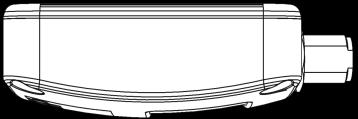
55 Side View 36 mm 88 mm 1m Figure 24 Side View 4.3 Accessories (Optional) The following accessories are available from AMEC. Contact our local dealer/agent for more details. Item Description Product Code Remark 1 VHF Antenna TENTA-11 Length: 1,200 mm 48
56 Limited warranty Subject to the terms, conditions and limitations set forth in this Worldwide Limited Warranty (hereinafter the Warranty ), AMEC warrants that its products, when properly installed and used, will be free from defects in material and workmanship for a period of twelve (12) months, from the date of first purchase (the Warranty Period ) For the purposes of this warranty, date of first purchase means the date that the product was purchased by the first retail customer, or by the institutional customer, or in the case of a product installed on a new vessel or any other marine related platform by a certified AMEC original equipment manufacturer (a AMEC OEM ), the date that such vessel was purchased by the first retail customer. AMEC will, at its sole option, repair or replace any defective products or components returned during the Warranty Period in accordance with the terms, conditions and limitations set forth below. Such repairs or replacement will be the sole remedy of the customer under this Warranty. 49
57 Standard Warranty Service To qualify for standard warranty service the product must be returned to a AMEC-certified service agent (i) within the Warranty Period, and (ii) within thirty (30) days of the alleged product failure. Any products returned must be securely packaged and sent pre-paid and insured to AMEC or to a AMEC-certified service agent. All products returned must be accompanied by a copy of the original sales receipt to be eligible for standard warranty service. Other conditions This Warranty is fully transferable provided that you furnish the original proof of purchase to the AMEC -certified service agent. This Warranty is void if the seal label is removed or defaced. THE LIABILITY OF AMEC TO A CUSTOMER UNDER THIS WARRANTY, WHETHER FOR BREACH OF CONTRACT, TORT, BREACH OF STATUTORY DUTY OR OTHERWISE SHALL IN NO EVENT EXCEED AN AMOUNT EQUAL TO THE TOTAL PURCHAE PRICE OF THE PRODUCT GIVING RISE TO SUCH LIABILITY AND IN NO EVENT SHALL AMEC BE LIABLE FOR SPECIAL, INCIDENTAL, CONSEQUENTIAL OR INDIRECT DAMAGES OR 50
58 LOST OF GOODWILL, REPUTATION, LOSS OF OPPORTUNITY OR INFORMATION, DATA, SOFTWARE OR APPLICATIONS. In the event that any term or provision contained in this Warranty is found to be invalid, illegal or unenforceable by a court of competent jurisdiction, then such provision shall be deemed modified to the extent necessary to make such provision enforceable by such court, taking into account the intent of the parties. All AMEC products sold or provided hereunder are merely aids to navigation. It is the responsibility of the user to exercise discretion and proper navigational skill independent of any AMEC product. 51
59 5 FCC INTERFERENCE STATEMENT This equipment has been tested and found to comply with the limits for a Class A digital device, pursuant to Part 15 of FCC Rules. These limits are designed to provide reasonable protection against harmful interference in a residential installation. This equipment generates uses and can radiate radio frequency energy and, if not installed and used in accordance with the instructions, may cause harmful interference to radio communications. However, there is no guarantee that interference will not occur in a particular installation. If this equipment does cause harmful interference to radio or television reception, which can be determined by turning the equipment off and on, the user is encouraged to try to correct the interference by one of the following measures: Reorient or relocate the receiving antenna. Increase the separation between the equipment and receiver. Connect the equipment into an outlet on a circuit different from that to which the receiver is connected. Consult the dealer or an experienced radio/tv technician for help. 52
60 This device complies with Part 15 of the FCC Rules. Operation is subject to the following two conditions: 1) This device may not cause harmful interference, and 2) this device must accept any interference received, including interference that may cause undesired operation. 6 DECLARATION OF CONFORMITY Hereby, Alltek Marine Electronics Corp. (AMEC) declares that this CYPHO-150/150S is in compliance with the essential requirements and other relevant provisions of Directive 1999/5/EC. 53
61 7 ACRONYMS AIS COG CPA CSTDMA DSC ECS ETA GPS IMO MMSI SOG SRM TCPA TDMA UTC VHF VTS Automatic Identification System Course Over Ground Distance to Closest Point of Approach Carrier-sense time division multiple access Digital Selective Calling Electronic Chart System Estimated Time of Arrival Global Positioning System International Maritime Organization Maritime Mobile Service Identity Speed Over Ground Safety Related Message Time to Closest Point of Approach Time Division Multiple Access Coordinated Universal Time Very High Frequency Vessel Traffic Service 54
62 Alltek Marine Electronics Corp 7F, No. 605, Ruei Guang Road Neihu, Taipei, 11492, Taiwan Tel: Fax: service@alltekmarine.com Website:
General Information Manual Edition 1.04
 General Information Manual Edition 1.04 i. Copyright The entire contents of this instruction manual, including any future updates, revisions, and modifications, shall remain the property of AMEC at all
General Information Manual Edition 1.14
 General Information Manual Edition 1.14 i. Copyright The entire contents of this instruction manual, including any future updates, revisions, and modifications, shall remain the property of AMEC at all
User s Manual COPYRIGHT DISCLAIMER
 COPYRIGHT The entire contents of this instruction manual, including any future updates, revisions, and modifications, shall remain the property of AMEC at all times. Unauthorized copies or reproduction
Smartfind M15, M15S & M15SW AIS Receiver User Manual
 Smartfind M15, M15S & M15SW AIS Receiver User Manual General Information i. Copyright The entire contents of this instruction manual, including any future updates, revisions, and modifications, shall remain
COPYRIGHT DISCLAIMER. Contact us at:
 COPYRIGHT The entire contents of this instruction manual, including any future updates, revisions, and modifications, shall remain the property of AMEC at all times. Unauthorized copies or reproduction
Sales & Marketing: Version 1.01
 User s Manual II COPYRIGHT The entire contents of this instruction manual, including any future updates, revisions, and modifications, shall remain the properties of AMEC at all times. Unauthorized copies
Manual Revision: Version 1.06
 COPYRIGHT The entire contents of this instruction manual, including any future updates, revisions, and modifications, shall remain the property of AMEC at all times. Unauthorized copies or reproduction
COPYRIGHT DISCLAIMER. Contact us at:
 COPYRIGHT The entire contents of this instruction manual, including any future updates, revisions, and modifications, shall remain the property of AMEC at all times. Unauthorized copies or reproduction
AIS 300 Installation Instructions
 Use these instructions to install the Garmin AIS 300 Automatic Identification System (AIS) Class B receiver device. Compare the contents of this package with the packing list on the box. If any pieces
KS-200A/B. ˵à Êé. AIS Class B Transponder KS-200A AIS Receiver KS-200B
 R KS-200A/B KS-200A/B ˵à Êé OPERATOR`S MANUAL AIS Class B Transponder KS-200A AIS Receiver KS-200B SAFETY INSTRUCTIONS Safety Instructions for the Operator WARNING Do not open the equipment. Only qualified
CAMINO-108S. AIS Class B with Integrated Splitter USER MANUAL
 CAMINO-108S AIS Class B with Integrated Splitter USER MANUAL COPYRIGHT The entire contents of this instruction manual, including any future updates, revisions, and modifications, shall remain the property
Manual Revision: Version 1.11
 COPYRIGHT The entire contents of this instruction manual, including any future updates, revisions, and modifications, shall remain the property of AMEC at all times. Unauthorized copies or reproduction
Installation and Quick Reference Guide. Disclaimer and warranty 2. Contents of this box 2. Brief background to AIS 3.
 AI3000 AIS Receiver ai3000vf rev 6b Installation and Quick Reference Guide Contents Page Number Disclaimer and warranty 2 Contents of this box 2 Brief background to AIS 3 Introduction 3 Installing the
CAMINO-108S. AIS Class B with Integrated Splitter USER MANUAL
 CAMINO-108S AIS Class B with Integrated Splitter USER MANUAL COPYRIGHT The entire contents of this instruction manual, including any future updates, revisions, and modifications, shall remain the property
Thank you for buying this AIS receiver.
 Thank you for buying this AIS receiver. This product has been engineered to offer you the highest level of performance and durability and we hope that it will provide many years of reliable service. We
NSPL-500. AIS/VHF antenna splitter. User Manual ENGLISH.
 NSPL-500 AIS/VHF antenna splitter User Manual ENGLISH www.bandg.com www.simrad-yachting.com www.lowrance.com Preface As Navico is continuously improving this product, we retain the right to make changes
ACT-IR220Li/220LN IrDA Serial Port Adapter
 ACT-IR220Li/220LN IrDA Serial Port Adapter Product Specification Summary ACTiSYS Corp. 48511 Warm Springs Blvd, Suite 206 Fremont, CA 94539, USA TEL: (510) 490-8024, FAX: (510) 623-7268 E-Mail: irda-support@actisys.com
ACT-IR220L/LE IrDA Serial Port Adapter
 ACT-IR220L/LE IrDA Serial Port Adapter Product Specification Summary ACTiSYS Corp. 48511 Warm Springs Blvd, Suite 206 Fremont, CA 94539, USA TEL: (510) 490-8024, FAX: (510) 623-7268 E-Mail: irda-support@actisys.com
RFTX-1 Installation Manual
 RFTX-1 Installation Manual complete control Universal Remote Control RFTX-1 Installation Manual 2009-2014 Universal Remote Control, Inc. The information in this Owner s Manual is copyright protected. No
Watcheye S AIS Splitter. manual
 Watcheye S AIS Splitter manual Thank you for buying this AIS antenna splitter. This product has been engineered to offer you the highest level of performance and durability and we hope that it will provide
Thank you for buying this AIS antenna splitter.
 Thank you for buying this AIS antenna splitter. This product has been engineered to offer you the highest level of performance and durability and we hope that it will provide many years of reliable service.
Technical Support, End User License & Warranty Information
 Technical Support, End User License & Warranty Information How to get Technical Support Pazzles provides free Technical Support for your Inspiration Vūe for a period of 1 year from the date of purchase.
ORiNOCO AP-4000MR-LR and AP-4900MR-LR Access Points Safety and Regulatory Compliance Information
 IMPORTANT! Visit http://support.proxim.com for the latest safety and regulatory compliance information for this product. ORiNOCO AP-4000MR-LR and AP-4900MR-LR Access Points Safety and Regulatory Compliance
LD2342 USWM V1.6. LD2342 V1.4 Page 1 of 18
 LD2342 USWM V1.6 LD2342 V1.4 Page 1 of 18 GENERAL WARNINGS All Class A and Class B marine Automatic Identification System (AIS) units utilize a satellite based system such as the Global Positioning Satellite
HIGH PERFORMANCE MARITIME. em-trak R100 PRODUCTS. AIS Dual Channel Receiver. Product Manual. High Performance Maritime Products
 em-trak R100 MARITIME PRODUCTS HIGH PERFORMANCE AIS Dual Channel Receiver Product Manual High Performance Maritime Products www.em-trak.com 201-0138:2 Contents 1 - Notices...1 1.1 - Safety warnings...1
Manual Revision: Version 1.30
 COPYRIGHT The entire contents of this instruction manual, including any future updates, revisions, and modifications, shall remain the property of AMEC at all times. Unauthorized copies or reproduction
CCR24T CCR24R. User s Guide WIRELESS TRANSMITTER SYSTEM WARRANTY SERVICE CARD WARRANTY CARD
 WARRANTY SERVICE CARD WARRANTY CARD PRODUCT NAME Wireless Transceiver System PERIOD MODEL NAME CCR24GEN YEAR PURCHASE DATE.. 200_ From the date of WARRANTY PERIOD.. 200_ purchase. CUSTOMER S ADDRESS :
INSTRUCTION MANUAL. IBRit - rf1 - usb PC - Station for wireless Data transmission. M e s s t e c h n i k. Messtechnik GmbH & Co.
 M e s s t e c h n i k INSTRUCTION MANUAL PC - Station for wireless Data transmission Document No. : D1F604 001 Version : April 2006 Copyright : IBR Messtechnik GmbH & Co. KG Contents 1. Introduction 1.1
User's Guide. Wireless AC Circuit Identifier. Models RT30 and RT32
 User's Guide Wireless AC Circuit Identifier Models RT30 and RT32 Introduction Congratulations on your purchase of Extech s Model RT30 (914Mhz) or RT32 (869MHz) Wireless AC Circuit Identifier. The detector
HIGH PERFORMANCE MARITIME. em-trak S100 PRODUCTS. Antenna splitter. Product Manual. High Performance Maritime Products
 em-trak S100 MARITIME PRODUCTS HIGH PERFORMANCE Antenna splitter Product Manual High Performance Maritime Products www.em-trak.com 201-0206:3 Contents 1 - Notices...1 1.1 - Safety warnings...1 1.2 - General
900MHz Digital Hybrid Wireless Outdoor Speakers
 4015004 900MHz Digital Hybrid Wireless Outdoor Speakers User s Manual This 900 MHz digital hybrid wireless speaker system uses the latest wireless technology that enables you to enjoy music and TV sound
Field Hub Installation Guide. P/N Rev. C 05/15
 Field Hub Installation Guide P/N016-0171-380 Rev. C 05/15 E21714 Copyright 2015 Disclaimer While every effort has been made to ensure the accuracy of this document, Raven Industries assumes no responsibility
Wireless Z-Wave Control ZRP-100US Z-Wave Repeater USER MANUAL. Introduction
 Wireless Z-Wave Control ZRP-100US Z-Wave Repeater USER MANUAL Introduction Thank you for choosing ZRP-100 Z-Wave Repeater product! ZRP-100 is a Z-Wave repeater with best RF performance to repeat Z-Wave
ANTENNA SpliTTEr. Zero loss active VHF antenna splitter. I N s t r u c t i o n m a n u a l
 ANTENNA SpliTTEr Zero loss active VHF antenna splitter I N s t r u c t i o n m a n u a l w w w. g m e. n e t. a u Thank you for buying this AIS antenna splitter. This product has been engineered to offer
User s Guide FM Transmitter
 TM 12-634 User s Guide FM Transmitter Please read this user s guide before using your new FM Transmitter. 12-634_en.indd 1 Package contents FM Transmitter USB Cable User s Guide Quick Start IMPORTANT SAFETY
AIS Training. AIS Technology in Digital Yacht Products Explained. Digital Yacht Ltd TEL
 AIS Training AIS Technology in Digital Yacht Products Explained Digital Yacht Ltd www.digitalyacht.co.uk TEL + 44 1179 554474 What is AIS? The Automatic Identification System (AIS) is the biggest advance
14 CHANNEL FAMILY RADIO SYSTEM MODEL # FR142
 14 CHANNEL FAMILY RADIO SYSTEM MODEL # FR142 2001 Audiovox Electronics Corp., Hauppauge, NY 11788 Printed in China 128-6020 052FR142104 BEFORE OPERATING THIS PRODUCT PLEASE READ THESE INSTRUCTIONS COMPLETELY
Disclaimers. Important Notice
 Disclaimers Disclaimers Important Notice Copyright SolarEdge Inc. All rights reserved. No part of this document may be reproduced, stored in a retrieval system, or transmitted, in any form or by any means,
User Manual Digital Wireless Rain Gauge
 Rain Gauge Specifications: User Manual Digital Wireless Rain Gauge - Outdoor rain gauge transmitter measures the rainfall and transmits the data to an indoor rain monitor base unit which shows the rainfall
USER MANUAL MODEL Parallel to Serial/ Serial to Parallel Interface Converter
 USER MANUAL MODEL 2029 Parallel to Serial/ Serial to Parallel Interface Converter C E R T I F I E D An ISO-9001 Certified Company Part #07M2029-B, Rev. C Doc. #102011UB Revised 6/16/09 SALES OFFICE (301)
Ditch Witch 750 Tracker Specs Provided by FOREWORD
 750/752 Display - FOREWORD 1 Ditch Witch 750 Tracker Specs Provided by www.aaatesters.com FOREWORD This manual is an important part of your equipment. It provides safety information and operation instructions
 Register your product and get support at www.philips.com/welcome English EN User manual Contents English 1 Important 4 Safety 4 Notice for USA 4 Notice for Canada 4 Recycling 4 2 Your SDV6122 5 Overview
User Guide SW212 Mity-Vox Wireless PA
 User Guide SW212 Mity-Vox Wireless PA Thank you for choosing the SW212 Mity-Vox Wireless PA from AmpliVox Portable Sound Systems. We are excited in introducing this truly unique system. Our system combines
Class B AIS Transceiver Mariner X2 Automatic Identification System
 Class B AIS Transceiver Mariner X2 Automatic Identification System INSTALLATION MANUAL Version 1.4 Thank you for buying this AIS Class B transceiver. This product has been engineered to offer you the highest
AIT2000 CLASS B AIS TRANSPONDER
 IMPORTANT NOTE The USB cable of the AIT2000 is designed to be used for configuring/programming the unit during installation and not for permanent connection to the boat s Navigation PC. If you intend to
Owner s Manual. MRX-2 Network Base Station
 Owner s Manual MRX-2 Network Base Station MRX-2 Owner s Manual 2014 Universal Remote Control, Inc. The information in this manual is copyright protected. No part of this manual may be copied or reproduced
Contents. Page English 1. French. Spanish. Reset of MIN/MAX records 915 MHz Reception Mounting Care and Maintenance Warranty Information
 Contents Language Page English 1 French Spanish WIRELESS 915 MHz TEMPERATURE STATION Instruction Manual TABLE OF CONTENTS Topic Page Inventory of Contents Features Setting Up Battery Installation Function
SP GHz Digital Wireless Speakers. User s Manual. Please read before using the equipment. Please visit for details.
 SP1390 2.4GHz Digital Wireless Speakers User s Manual Please read before using the equipment. Please visit www.promowide.com for details. INTRODUCTION This 2.4G digital wireless speakers system uses latest
PTT- Z or PTT-U PUSH-TO-TALK Specification
 Federal Communication Commission Interference Statement This equipment has been tested and found to comply with the limits for a Class B digital device, pursuant to Part 15 of the FCC Rules. These limits
TARGETuner Antenna Management System for Screwdriver Antennas
 TARGETuner Antenna Management System for Screwdriver Antennas www.westmountainradio.com 1020 Spring City Drive Waukesha, WI 53186 262-522-6503 sales@westmountainradio.com 2014, All rights reserved. All
Operating Instructions
 3000 Operating Instructions Contents Introduction 1 Operating Instructions 2-4 Demonstrations 5-6 Storing/Handling/Cleaning 7 Safety Precautions 7-8 Specifications 8 FCC Compliance Statement 9-10 Limited
M508 GPS Tracking Device
 M508 GPS Tracking Device (GPS+GPRS+GSM) Product Manual Edition 1.3 Copyright 10 th Oct., 2009 GATOR GROUP CO.,LTD. All rights reserved. http://www.gatorcn.com China Printing ADD: 312# Ansheng Building,Xixiang
CRUX II/BTGPS USER GUIDE. Model:D1598
 CRUX II/BTGPS USER GUIDE Model:D1598 0 Federal Communication Commission Interference Statement This equipment has been tested and found to comply with the limits for a Class B digital device, pursuant
SRT Marine Technology. LD2342 V1.4 Page 1 of 22
 LD2342 V1.4 Page 1 of 22 LD2342 V1.4 Page 2 of 22 2 LD2342 V1.4 Page 3 of 22 GENERAL WARNINGS All marine Automatic Identification System (AIS) units utilise a satellite based system such as the Global
Active Transmitter Combiner 8:1 AC 3200-II. Instruction manual
 Active Transmitter Combiner 8:1 AC 3200-II Instruction manual Contents Contents Important safety instructions... 2 The AC 3200-II active transmitter combiner 8:1... 4 Delivery includes... 4 Connection
Installation & Quick Start Guide AIT2000 Class B AIS Transponder
 Installation & Quick Start Guide AIT2000 Class B AIS Transponder QUICK START AIT2000 - VR1.01 1. Introduction Congratulations on the purchase of your AIT2000 Class B AIS Transponder. It is recommended
INSTALLATION AND OPERATING MANUAL
 INSTALLATION AND OPERATING MANUAL FOR RBDA-PCS-1/25W-90-A INDOOR REPEATER TABLE OF CONTENTS PARAGRAPH PAGE NO BDA OVERVIEW 3 BDA BLOCK DIAGRAM DESCRIPTION 3 FCC INFORMATION FOR USER 3 BDA BLOCK DIAGRAM
Owner s Manual. MRX-2 Network Base Station
 Owner s Manual MRX-2 Network Base Station MRX-2 Owner s Manual 2014 Universal Remote Control, Inc. The information in this manual is copyright protected. No part of this manual may be copied or reproduced
Thank you for buying this AIS Class B transceiver.
 Thank you for buying this AIS Class B transceiver. This product has been engineered to offer you the highest level of performance and durability and we hope that it will provide many years of reliable
Installation & Quick Start Guide CLB2000 Class B AIS Transponder
 Installation & Quick Start Guide CLB2000 Class B AIS Transponder QUICK START CLB2000 - VR1.01 1. Introduction Congratulations on the purchase of your CLB2000 Class B AIS Transponder. It is recommended
Quick Start Guide. Version: 1.0 F/W: V1.2.0_RC1b. Date: December 11, 2017
 VigorAP 920R Series Ruggedized Outdoor AP with Extreme 802.11ac Power Warranty Quick Start Guide Version: 1.0 F/W: V1.2.0_RC1b Date: December 11, 2017 We warrant to the original end user (purchaser) that
Manual and User Guide
 Manual and User Guide TV Talker FM System Model WFM 260 Model WFM 270 Transmitter Model WFM TX260 Receiver Model WFM RX260 Receiver Model WFM RX270 MAN 151H 2011 Williams Sound, LLC Contents Page System
NEO CAR AUDIO. Neo AUXiN AUX INPUT INTERFACE. Instruction Manual
 NEO CAR AUDIO Neo AUXiN AUX INPUT INTERFACE Instruction Manual IMPORTANT NOTE Neo AUXiN Dip switch positions MUST be set BEFORE any other step is taken. Otherwise, the kit will not operate properly. See
Owner s Manual MRX-10 Advanced Network System Controller
 Owner s Manual MRX-10 Advanced Network System Controller MRX-10 Owner s Manual 2015 Universal Remote Control, Inc. The information in this Owner s Manual is copyright protected. No part of this manual
Ambient Weather F007TP 8-Channel Wireless Probe Thermometer User Manual
 Ambient Weather F007TP 8-Channel Wireless Probe Thermometer User Manual Table of Contents 1 Introduction... 2 2 Getting Started... 2 2.1 Parts List... 2 2.2 Probe Thermometer Sensor Set Up... 2 3 Remote
RM24100D. Introduction. Features. 2.4GHz 100mW RS232 / RS485 / RS422 DSSS Radio Modem (IEEE compliant) Operating Manual English 1.
 Operating Manual English 1.") RM24100D 2.4GHz 100mW RS232 / RS485 / RS422 DSSS Radio Modem (IEEE 802.15.4 compliant) Operating Manual English 1.09 Introduction The RM24100D radio modem acts as a wireless serial cable replacement and
RM24100D 2.4GHz 100mW RS232 / RS485 / RS422 DSSS Radio Modem (IEEE 802.15.4 compliant) Operating Manual English 1.09 Introduction The RM24100D radio modem acts as a wireless serial cable replacement and
Pocket Weatheradio with Tone and Vibrating Alert
 Pocket Weatheradio with Tone and Vibrating Alert OWNER S MANUAL Please read before using this equipment. Your RadioShack Pocket Weatheradio is designed to receive National Weather Service (NWS) broadcasts,
Rock Sounders. Weatherproof Wireless 900MHz Speaker System. User Guide. Model no.: GDI-AQRCK400 / AQRCK41
 Rock Sounders Weatherproof Wireless 900MHz Speaker System User Guide Model no.: GDI-AQRCK400 / AQRCK41 Please read before using the equipment IMPORTANT: Please read your User s Guide before using your
The FA-50 offers accurate information for collision avoidance
 The FA-50 offers accurate information for collision avoidance with GPS antenna GPA-017S FURUNO s FA-50 class-b AIS transponder receives navigation data from AIS-equipped vessels nearby that can be utilized
IS76 Beacon with Ferrite Antenna Installation Manual
 IS76 Beacon with Ferrite Antenna Installation Manual Edition: June 2016 Document N : F.01U.136.807 V3 Page 1 of 10 Document No F.01U.136.807 V3 IS76 Beacon with Ferrite Antenna: Installation Manual Edition:
Schooners II. Weatherproof Wireless 900MHz Speaker System. User Guide. Model no.: GDI-AQSHR200 / AQSHR21
 Schooners II Weatherproof Wireless 900MHz Speaker System User Guide Model no.: GDI-AQSHR200 / AQSHR21 IMPORTANT: Please read your User s Guide before using your system INTRODUCTION Your SCHOONERS II speaker
RM24100A. *Maximum transmit power output levels and local radio frequency regulator bodies must be obeyed in the country of operation.
 RM24100A 2.4GHz 100mW RS232 / RS485 / RS422 DSSS Radio Modem (IEEE 802.15.4 compliant) Operating Manual English 1.02 Introduction The RM24100A radio modem acts as a wireless serial cable replacement and
A-16D A-Net Distributor
 A-16D A-Net Distributor For use with the Personal Monitor Mixing System Information in this document is subject to change. All rights reserved. Copyright 2003 Aviom, Inc. Printed in USA Document Rev. 1.03
Manual Unihan UPWL6024
 Manual Unihan UPWL6024 Federal Communications Commission Statement This device complies with FCC Rules Part 15. Operation is subject to the following i. This device may not cause harmful interference,
900 MHz Digital Wireless Indoor/Outdoor Speakers
 4015007 900 MHz Digital Wireless Indoor/Outdoor Speakers User s Manual This 900 MHz digital hybrid wireless speaker system uses the latest wireless technology that enables you to enjoy music and TV sound
Product Manual. Getting Started with Roadie 2.
 MOL NUMBER RD200 Product Manual Getting Started with Roadie 2. This manual is a quick start guide for Roadie 2. Please read the following instructions and conditions before using Roadie 2. For a more comprehensive
INSTRUCTION MANUAL MODEL SAS RS-7 LASER DISTANCE METER
 INSTRUCTION MANUAL MODEL SAS RS-7 LASER DISTANCE METER KEYS, DISPLAYS AND FUNCTIONS GENERAL SAFETY RULES! DANGER! Do not aim light at persons or animals. Do not stare into the laser light source. Laser
User Manual. ProRF Encoder Transmitter & Receiver
 User Manual ProRF Encoder Transmitter & Receiver WARRANTY Accurate Technology, Inc. warrants the ProScale Systems against defective parts and workmanship for 1 year commencing from the date of original
USER MANUAL MODEL: BM-162
 USER MANUAL MODEL: BM-162 Parents Unit: A. Name Power ON/OFF Key Music Key PTT Key Volume - Key Microphone Power & Low battery indicator LCD display Volume + Key Night Light and torch Key Speaker -Belt
easypos N HOOK - Transmitter Manual
 easypos N HOOK - Transmitter Manual easypos N HOOK Maritime Locating System Product No.: A140 Rev. 1.4 Weatherdock AG. Sigmundstraße 180 D-90431 Nürnberg Tel. :+49 911 37 66 38 30 Fax: +49 911 37 66 38
USER MANUAL. Sens it SENS IT 2.4
 USER MANUAL www.sensit.io Sens it SENS IT 2.4 SUMMARY SAFETY INSTRUCTIONS 4 I. CONTENT OF THE PACK 4 II. PRESENTATION 5 III. HOW TO START 8 IV. TECHNICAL SPECIFICATIONS 9 V. WARNING STATEMENTS 10 VI. CREDITS
IS7705. Installation & Operation Manual AUDIO INTEGRATION KIT. TranzIt LINK
 GET CONNECTED Installation & Operation Manual AUDIO INTEGRATION KIT IS7705 Note to Readers, The information contained within the following documentation is subject to change without notice. Features discussed
DIGICELL ANYNET NETWORK ACCESS MODULE
 Comm Activity Network Status Service DigiCell Any NET Network Access Module Network Interface Network Service AMPS Cellemetry GSM SMS CDMA GPRS Ethernet 1xRTT RS-232 TCP/IP Input 1 Standard S3 off, S4
AM/FM Stereo Headset Radio
 User s Guide 12-590 AM/FM Stereo Headset Radio Thank you for purchasing your AM/FM Stereo Headset Radio from RadioShack. Please read this user s guide before installing, setting up, and using your new
Power Genius XL User Manual rev 10.
 Power Genius X User Manual rev 10. 1/23 Table of Contents 0. Important notice...3 1. Unpacking...5 1.1. Front Panel...5 1.2. Back Panel...6 1.3. BCD/PTP connector pinout...8 2. Using with Radios...9 2.1.
NC Models. CP390i - GPS Chart Plotters. Addendum to Owner s Manual Issue C to update to Software Version (*)
") CP390i - GPS Chart Plotters (*) NC Models to Owner s Manual Issue 16.50 C 300311 to update to Software Version 16.70 BUILT-IN CHARTS ARE NOT INSTALLED The following paragraphs/pictures are not applicable:
CP390i - GPS Chart Plotters (*) NC Models to Owner s Manual Issue 16.50 C 300311 to update to Software Version 16.70 BUILT-IN CHARTS ARE NOT INSTALLED The following paragraphs/pictures are not applicable:
Manual Unihan UPWL6025
 Manual Unihan UPWL6025 Federal Communications Commission Statement This device complies with FCC Rules Part 15. Operation is subject to the following i. This device may not cause harmful interference,
802.11n, 2.4G 1T1R Wireless LAN PCI Express Half Mini Card
 802.11n, 2.4G 1T1R Wireless LAN PCI Express Half Mini Card WN6605LH Realtek RTL8191SE User s Manual Ben J. Chen 3/4/2010 Federal Communication Commission Interference Statement This equipment has been
Gypsy Statement of Limited Warranty. Part 1 General Terms
 Gypsy Statement of Limited Warranty Part 1 General Terms This Statement of Limited Warranty includes Part 1 General Terms, and Part2 Warranty Information. The warranties provided by PROVO CRAFT AND NOVELTY,
Installation and Operation Manual MSI. Multi-Sensor Interface Hub. Interface Module for all Sensors Network and Wireless CAUTION
 Installation and Operation Manual MSI Multi-Sensor Interface Hub Interface Module for all Sensors Network and Wireless CAUTION This equipment complies with the limits for a Class B digital device, pursuant
Ambient Weather F007TH Wireless Thermo-Hygrometer User Manual
 Ambient Weather F007TH Wireless Thermo-Hygrometer User Manual Table of Contents 1 Introduction... 2 2 Getting Started... 2 2.1 Parts List... 2 2.2 Thermo-Hygrometer Sensor Set Up... 2 3 Remote Sensor Installation...
HIGH PERFORMANCE MARITIME PRODUCTS. em-trak B212 AIS Class B Transceiver. Product Manual. High Performance Maritime Products.
 em-trak B212 AIS Class B Transceiver MARITIME PRODUCTS HIGH PERFORMANCE Product Manual High Performance Maritime Products www.em-trak.com Thank you for buying this AIS Class B transceiver. This product
MODEL 3810/2 Line Impedance Stabilization Network
 EMC TEST SYSTEMS FEBRUARY 1996 REV C PN 399197 MODEL 3810/2 Line Impedance Stabilization Network OPERATION MANUAL USA P.O. Box 80589 Austin, Texas 78708-0589 2205 Kramer Lane, Austin, Texas 78758-4047
SPM-50 RF Spectrum Power Meter PC Software User Manual
 SPM-50 RF Spectrum Power Meter PC Software User Manual Shineway Technologies, Inc. Notices Copyright 2014, ShinewayTech, All rights reserved. No part of this manual may be reproduced in any form or by
The FA-30 delivers Real-Time AIS information to navigation systems providing critical collision avoidance information
 The FA-30 delivers Real-Time AIS information to navigation systems providing critical collision avoidance information Acquisition and tracking of traffic around your vessel is absolutely necessary for
Blue Point Engineering
 Overview Blue Point Instruction Board 2-CH Boards, Terminal Block and Ribbon Cable I Type: RF Radio (315 MHz) 1-2 Channels (FCC Part 15 Compliant Components). Operating Voltage: 6-15 VDC @ 1 Amp (Wall
MedRx Avant Polar HIT AH-I-MPHITS-5 Effective 11/07/11
 INSTALLATION MANUAL 2 Contents Getting To Know Your AVANT POLAR HIT TM... 4 Setting up the System... 6 Software Installation... 7 Driver Installation Windows 7... 10 Driver Installation Windows XP... 13
Radio Controlled timekeeping. Receives 60KHz WWVB signal transmitted by NIST in Fort Collins, Colorado
 Congratulation on your purchase of an Atomix Radio Controlled clock. Radio Controlled technology allows for the most accurate time keeping available as well as automatic changes for Daylight Saving Time
Ambient Weather F007PF 8-Channel Wireless Water Thermometer User Manual
 Ambient Weather F007PF 8-Channel Wireless Water Thermometer User Manual Table of Contents 1 Introduction... 2 2 Getting Started... 2 Parts List... 2 2.1 Water Thermometer Sensor Set Up... 2 3 Glossary
Using the USB Output Port to Charge a Device
 Table of Contents ----------------------------------- 2 Features ----------------------------------------------- 3 Controls and Functions ---------------------------------- 4 ER210 Power Sources -----------------------------------